

Page 1
^ m
■
c/>
> <
o
(0
«1
e
NOTICE 37
PLAYBACK
nPf^RATION 35
O
RECORDING
OPERATION 20
0
PREPARATION 9 INTRODUCTION 2
Page 2

PLEASE READ
CAUTION
RISK Of ELECTRIC SHOCK
DO NOT OREN
A
The lightning flash with arrowhead symbol, within an equilateral triangle,
is intended to alert the user to the presence of uninsulated “dangerous
voltage" within the product’s enclosure that may be of sufficient magni
tude to constitute a risk of electric shock to persons.
CAOTKPN: to reduce THE RISKOF ELEC
TRIC SHOCK, DO NOT REMOVE COVER(OR
BACK). NO USER SERVICEABLE PARTS IN
SIDE. REFER SERVICING TO QUAUF1EQ
SERVICE PERSONNEL.
WARNING: TO REDUCE THE RISK OF FIRE OR ELECTRIC SHOCK, DO NOT EXPOSE THIS
APPLIANCE TO RAIN OR MOISTURE^ DANGEROUS HIGH VOLTAGES ARE PRESENT
INSIDE THE ENCLOSURE. DO NOT OPEN THE CABINET. REFER SERVICING TO
QUALIFIED PERSONNEL ONLY.
NOTE: This equipment has been tested and found to comply with the limits for a Class A
digital device, pursuant to Part 15 of the FCC Rules. These limits are designed to
provide reasonable protection against harmful Interfermce when the equipment is
operated in a commercial envftonment. This equipment generates, uses, and can
radiate radio frequency energy and, if not installed and used In accordance with the
instruction manual, may cause harmful interference to radio communications.
Operation of this equipment in a residential areals likely to cause harmful interference
in which case the user will be required to correct the interference at his own expense.
In the spaces provided below, record the Model and Serial No. located at the rear of your video cassette
recorder.
Modei No.
Retain this information for future reference.
The exclamation point within an equilateral triangle is intended to alert
the user to the presence of important operating and maintenance
(servicing) instructions in the literature accompanying the appliance.
Sériai No.
-•fi
ÜÎ0ÎλORTANT precautions
This
VCR
Only cassettes marked ¡VH^l can be use with the VCR.
Save Original Packing Materials
The original shipping carton and packing materials will come in handy if you ever have to ship your VCR. For maximum protection,
repack the set as it was originaiiy packed at the factory.
Surface Damage -
This VCR is covered with a dear plastic, to protect the top cover surface during shipping and handling. Daiiy wear may resuit in dents
or craCtra in the plastic which appear as white marks or other kinds of apparent surface damage. This does not mean that your VCR
itself is damaged. If damage to this coating is extensive, simply peel it off.
Dew Condensation
Never operate this unit immediately after moving it from a cold location to a warm location. When the VCR is exposed to such a change
in temperature, dew condensation may occur on the cylinder inside it, one of its most crucial internal parts. The unit is equipped with
an automatic dew condensation prevention circuit designed to cope with this problem. It takes about TWO HOURS for this circuit to
work with the power cord plugged in. Please do not use the VCR during this time.
-Daily Maintenance-
Before beginning the day's operation, rewind the cassette tape recorded on the previous day a few counts and play it back to check
for proper recording.
is not compatibie with ordinary
IVHSlVCRs-
Copyright; To record video tapes and other material only In the event that third party copyrights and other rights are not
violated.
Page 3
Introduction
Possible to record over periods as long as 960 hours.
With use of T-120 tape it is possibie to record over periods
of A2, A12, A24, 24, 48, 72, 120, 168, 240, 480, 720 and
960 hours as well as to carry out One-shot recording.
Internal time4iate generator.
The unit inciudes an intemai time-date generator, a must
for observation puiposes.
Mode setting with monitor screen.
Menu screens are used for setting the various function
modes including the timer setting and aiarm recording
modes.
Timer recording possible.
It is possible to set one program for each day of the week
as well as one daily program for a total of 8 programs.
One-shot recording possible.
External trigger input makes it possible to record from 1 to
32 fields and Manual mode.
Possible to display remaining tape time.
It is possible during both recording and playback to cheeky
the average time remaining until tape end.
Alarm record function.
Input of an alarm signal when an abnormality occurs
makes it possible to automatically switch over to a time
mode set for recording.
Alarm memory function.
This unit includes a handy alarm memory function for
finding the alarm recording section.
Repeat recording possible.
Repeat recording function makes it possible to automati
cally return to the beginning of tape and repeat recording
when the tape is finished.
Recording mode lock function, power failure restart recording possible.
This unit includes a recording mode lock function in order
to insure proper function when operating over long perio
for sun/eillance and observation. There is also a power
failure restart function for automatically going to the
recording mode following restoration of power after a
power failure.
Wide choice of playback functions.
A wide variety of playback functions realizes quick and
efficient checks of recorded contents. They include picture
search, field feed playback, reverse playback, reverse field
playback, still playback and etc.
Clean slow and clean still.
Clean slow playback and clean still picture free of noise
and flutter are possible in the time-lapse mode. These are
useful for determining recorded material.
Includes head cleaning function.
U'
Head cleaning is carried out at the end of timer recording
,rrt“
bi
and at tape end in order to prevent head jamming.
There is also head cleaning once every two hours when
Ip
operating in time modes of 48 hours or more.
Wired remote control function
The wired remote control allows the following VCR
functions.
• Fast Forward • Forward picture search
•REWIND • Reverse picture search
• PAUSE • STILL
• Field advance {forward, reverse)
• Play • STOP
• Play back time
When the option l/F (Interface Board) is added, the
information from the ATM (Automatic Teller Machine) or
the cash register is superimposed on a picture and the
picture can be recorded.
PLEASE READ
..............................................................
IMPORTANT PRECAUTIONS.........................................1
INTRObUCTfON
FEATURES
TABLE OF CONTENTS
INSTRUCTIONS IN BRIEF
VCR DISPLAY
WIRED REMOTE CONTROL
PREPARATION
..........................................................
...............................................................
.............................................
.........................................
...........................................................
.....................................
.......................................................
9-19
2-8
CONNECTIONS.........................................................9
CONTENTS OF SCREEN DISPLAY
SETTING THE CLOCK
ON-SCREEN FUNCTIONS
DISPLAY SCREEN
..........................................
.......................................
..................................................
.........................
11
...12
COUNTER DISPLAY................................................16
SETTING THE HECORDING/PLAYBACKTIME
.........
LOADING AND UNLOADING A VIDEO CASSETTE.19
13
14
18
1
RECORDING OPERATION......................................20 - 34
RECORDING...........................................................20
RESTART RECORDING .........................................21
2
2
3
7
8
TIMER RECORDING................................................22
ONE-SHOT RECORDING
........................................
26
ALARM RECORDING..............................................28
setting OF OPERATION AFTER TAPE END DETECTION ..31
AUTO REWIND AFTER RECORDING......................32
REPEAT RECORDING
............................................
33
RECORDING WITH THE SEQUENTIAL SWITCHER.34
PLAYBACK OPERATION........................................35 - 37
PLAYBACK
PLAYBACK IN VARIOUS MODE
NOTICE
................................................................
............................................................
.............................
37-43
35
36
SIGNAL LEVELS OF INPUT/OUTPUT......................37
DAILY AND PERIODIC INSPECTION
.......................
38
CAUTIONS DURING USE........................................40
BEFORE CALLING SERVICE PERSONNEL............41
SPECIFICATIONS..........................................Back cover
Page 4
INSTRUCTIONS IN BRIlEii
® POWER button
Press to turn the power ON and OFF,
d) EJECT button
Press to eject the cassette automatically from the cassette
compartment.
<3> REW button
> Press to rewind the tape when the tape is stopped.
• Press during playback to play back the picture at 6 times
the normal speed in the reverse direction.
• Press during stilt picture playback to advance (reverse)
the picture by one field.
® PLAY button
Press to start the playback mode.
iji FF button
• Press to make fast-forward tape running when the tape is
stopped.
• Press during playback to play back №e picture at 5 times
the normal speed in the forward direction.
• Press during still picture playback to advance (reverse)
the picture by one field.
® STOP button
Press to stop tape running.
® PAUSE button
• Press during recording to stc^ the tape running and
recording.
• Press during playback to stop the tape running and
display a stilt picture.
® REC button
Press to start recording in the mode selected.
® BUZZER switch
This switch is the on/off switch for the buzzer. The buzzer
will sound in different ways depending on conditions of the
VCR. When condensation occurs in the heads (DEW), the
buzzer will sound continuously. When toe tape reaches its
end in the record mode, toe buzzer will sound continu
ously. The buzzer may be cancelled by setting (off) this
switch. The buzzer will beep five times if the recording is
performed wito the record protect tab removed and when
the timer button is pressed,
® PICTURE control
Adjust to soften or sharpen the picture during playback.
® TIMER button
Press to set timer recording.
Q> R.PLAY (Reverse Playback) button
Press during playback to play back in the reverse direc
tion.
Page 5

® HOUR METER button
The time that the equipment has been used is displayed in
the counter display.
When this button is pressed, the total usage time is
displayed for five seconds. Next, ttie usage time since the
last maintenance is displayed for five seconds. Following
this, the display returns to the counter display.
Total time: Max. 9999 hours x 10 (99990)
(approximate value)
Time since the last maintenance:
Max. 999 hours x 10 (9990)
(approximate value)
The time display is useful for maintenance and checks.
® DISPLAY button
Press to display a menu on the screen. Use this button
when you wish to change.
® SHIFT button
Used to set a mode and times on the menu screen.
® SET button
Used to make settings on the menu screen or set times.
Press either the + or the - button and adjust to the
numerical value or item that you want to set.
€> COUNT, button
Press to display the tape counter or tiie alarm counter on
the VCR DISPLAY.
® COUNT. MEMORY button
• Press once to appear the "COUNT. M" (counter memory)
on the VCR display. When the tape is fast-forwarded or
rewound during this mode, tiie-tape will stop at a count of
"0000".
• Press twice to appear the "ALARM M" (alarm memory)
on the VCR display. When the tape is fast-forwarded or
rewound during this mode, the tape will stop automati
cally at the beginning of an alarm and this VCR enters
the STILL, PLAYBACK mode.
• Press three times to cancel this function.
® RESET buttjpn
• Press to reset the tape counter to "0000" during the tape
counter mode.
• Press to reset the alarm counter to "A-00" during the
alarm counter mode.
® TAPE REMAIN button
As long as this button is depressed, the remaining tape
time is displayed in the counter display. The remaining
time is the approximate time to tape end when used in the
A2-hour mode,
® TRACKING buttons ( v / a )
Adjust to eliminate noise from your picture during play
back.
® TIME MODE buttons ( V / A )
Used to set ttia recording and playback time modes.
Press either the a button or v button and adjust for the
time mode you wish to set.
® MODE LOCK switch
OFF: Used for normal operation.
ON: Operations buttons will not operate.
® VCR DISPLAY
® CASSETTE COMPARTMENT
When a cassette is inserted into the cassette compart
ment, the mechanism will automatic^ly load the tape Into
this VCR.
Page 6

Rear Panel
é ®
BATTERY cover
® REMOTE jack
Accepts the plug from the remote control.
® MIC IN jack
Accepts audio signals from a microphone, in this case the
RCA jack input will be switched off.
® ALARM IN terminal
Signal input terminal to start alarm recording.
The VCR goes to alarm recording mode when the terminal
is connected to the ground terminal during recording.
® ALARM RESET terminal
Signal input terminal to release alarm recording.
Alarm recording is released when the terminal is con
nected to the ground terminal during alarm recording.
(D ALARM OUT terminal
Output terminal to transmit the alarm signal to an external
equipment.
A voltage of DC +5V is output during alarm recording.
® ONE SHOT IN terminal
■' Used for One-shot recording.
® REC TRIGGER OUT terminal
Signal output terminal to control the switching timing of tiie
camera when connected writh the sequential switcher.
® VIDEO IN connector (BNC)
Used to record external video signals by connecting to the
video output jack of an external video source such as a
camera, etc.
® VIDEO OUT connector (BNC)
Used to connect to a monitor TV.
® POWER CORD
Insert to an 120V AC outlet.
Note:
------------------------------------------------------------
This VCR allows recording of characters and numerical
information sent from the ATM (Automatic Tetter Machine),
Cash Register and superimposed on the screen by cwinecting the specified l/P (Interface Board) to tire I/O connector on
rear of the unit.
When you wish to obtain the t/F Board, please consult
TOSHIBA AMERICA C.P. INC. (See MANUAL Back cover)
The mounting of the 1/F Board is allowed only by a qualified
service man.
For details on the mounting, refer to the Instruction Manual
supplied with the 1/F Board.
® AUDIO IN jack (RCA type)
Used to record external audio signals by connecting to the
audio output jack of an external audio source.
. ® AUDIO OUT jack (RCA t^)
Used to connect to the audio input jack of external audio
equipment.
Page 7

A Word on the Exclusive 3N-100AAS
Battery Pack
The TOSHIBA nIckel'Cadmium battery pack (3N-100AAS) is
used for power source of the built-in clock and memory circuit.
Charging the Battery Pack
1. Turn on the VCR,
2. The battery pack in the VCR is charged.
Battery Installation_________________________
Removal:
1. Remove the battery cover.
2. Disconnect the connector in the VCR.
__________________
Specification of Battery
■ Temperature
For charging
For operating
For storing
■ Charging time
Notes: -----------
Use onEy for this VCR.
Do not dispose of the batteries into fire.
Do not short circuit the terminals.
Do not modify or disassemble.
Avoid dropping, unnecessary shocks.
O-C to 80“C
-20“C to 80-C
-30“C to eo"c
more than 48 hours
Connector
Installation:
1. Install the battery pack, connect the connector on the
battery pack to this VCR.
Make sure the polarities {+} and (-) are correct.
2. Close the battery cover.
Note:-------------------------------------------------------------
If the Battery Pack is removed, the memory data will be
erased. In such a case, perform the setting from the first step.
Battery pack
^^009
Page 8

VcrIísPEI®
IPLAYI IrEC]
T T T - g
COUNT, ALARM
n n n n
u u u u
rDEW
TIMER
PW.FAIL
o u u
U U Lí
¿ ¡¿i II Lia
I
Cassette indicator
Lights when a tape is inserted.
I Counter memory indicator
Lights when the counter memory is operated.
I Aiarm Memory indicator
Lights when the alarm memory is operated.
I Aiarm Indicator
Lights during aiarm recording and biinks when the alarm
recording completes.
I PW.FAIL (Power Failure) Indicator
Blinks when a power failure occurs.
I
TAPE Footage Indicator
Displays as shown below, depending on operational
modes.
I Counter/Alarm Counter/Remaining Tape/TIme Used/
Error Message indicator
• Press the COUNT, button to display the alaim counter.
• Press the TAPE REMAIN button to display the remaining
tape time.
• Press the HOUR METER button to display the total
usage time.
■ Press this button twice to display the usage time since
maintenance.
• Press this button three times to cancel this function.
• When an abnormality occurs during operation, the error
code is displayed.
E-1: Abnormality on reel rotation during tape mnning.
E-3; Abnormality on cylinder rotation during recording
and playback.
E-4: Abnormality on tape loading mechanism.
E‘5: Video tape is cut.
£-6; Head dog.
E-8: Dew condensation,
I
Dew indicator
Blinks when condensation has developed inside the video
unit.
\ Timer indicator
Lights when the timer recording button is pressed.
Record/PlaytMck Time indicator
] Displays record/playback time mode.
Playback
Playback
Still
Slow
Field Advance
Reverse
Playback
Forward
Picture Search
Reverse
Picture Search
Reverse
Field Advance
iPLAYl
jPLAYl
II
|PLAY|
1 ►
|PLAY|
II »>
|PLAY|
4
|play|
IplayI
|play|
-ni
►
Other than playback
Record
Pause
Time-lapse
One Shot
Recording
Field
Advance
Fast Forward
Rewind
[M!
►
|RECl
II
flicl
1 ►
1 ►
fREC]
II >
44
Page 9
® PAUSE/STILL button
• Press during recording to pause the recording.
• Press during playback to play back a still picture.
REW/Reverse Picture Search button
• Press to rewind the tape.
• Press during playback for reverse picture search. To
release the reverse picture search mode, press the
PLAY button.
• Press the REW button while pressing the PLAY button
and the time mode can be selected.
• Press the REW button during still playback mode and the
Reverse Field Advance playback will be carried out.
® STOP button
Press to stop tape running.
0
PLAY button
Press to start play back.
0 FF/Fast Forward/Forward Picture Search button
• Press for fast forward mode.
• Press during playback for fonward picture search mode.
To release this mode, press the PLAY button.
• Press the FF button while pressing the PLAY button and
the Tima mode can be selected.
• Press the FF button during still playback mode and the
Reverse Field Advance playback will be carried out.
8
Page 10
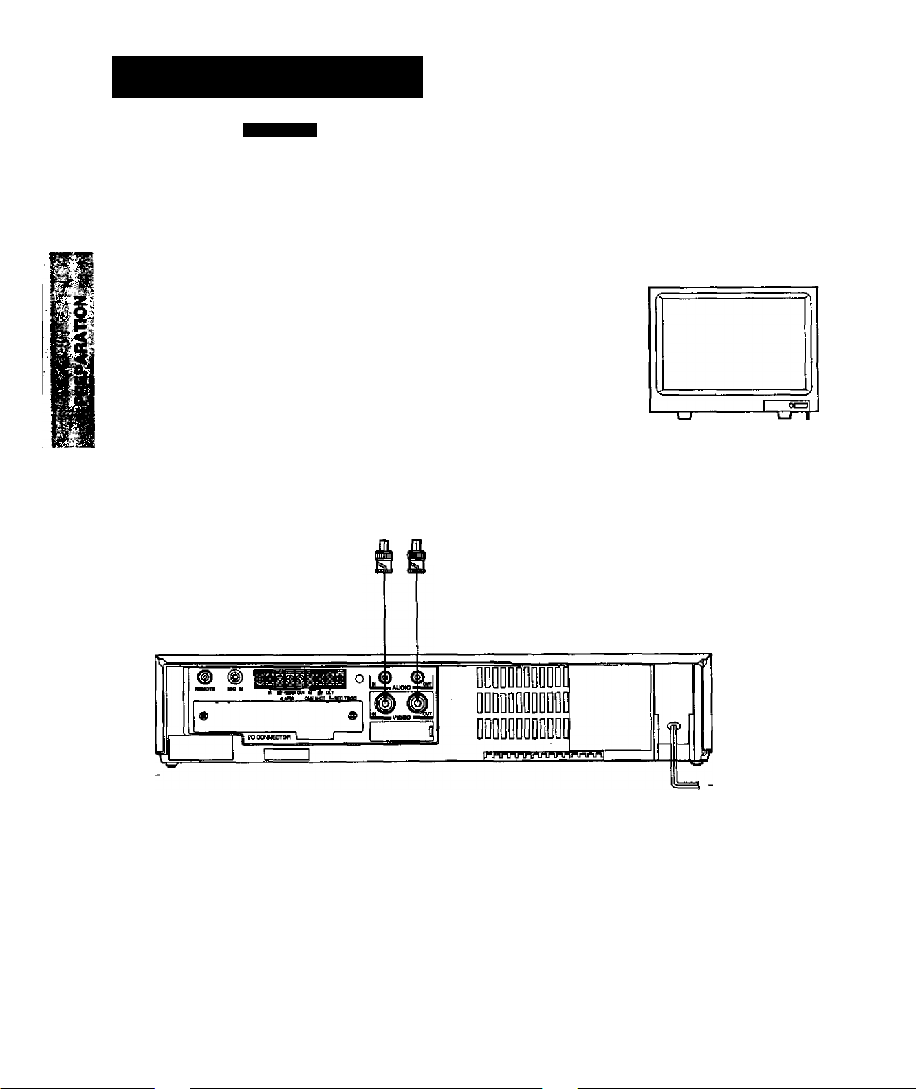
Preparation
Connection to Camera
Example:
Monitor TV
camera
To VIDEO OUT (BNC connector)
To VIDEO IN
(BNC Connector)
To VIDEO IN (BNC connector)
3C-2V or 5C'2V coaxial cable.
To VIDEO OUT
(BNC Connector)
TO AC OUTLET
(120V)
TO AC OUTLET
(120V)
Page 11

EXAMPLES OF CONNECTION WITH THE FIELD SEQUENTIAL SWITCHER
For further details, consult the instruction manuais of the devices for connection.
When connected to the switcher, set the Aiarm Recording of this unit to CONT.
® ® iMMi °
VOOON EC *0*
MnnruTnrvwnnnnnnni
To ALARM IN ■
To ALARM ■
RESET
Frame Sequential Switcher
To VCR playback
hTo REC
TRIGG.
OUT
— To VIDEO OUT
-To VIDEO IN
-ToVCRREC
-To GND
-To ALARM OUTPUT
-To REC TRIGGER INPUT
TO AC OUTLET
(120V)
nil
4
of
X
I
1
When using the VCR connected to a frame sequential switcher, pay atten
tion to the following matters.
■ When playing back in the A12-hour or A24-hour mode, mixing of pictures from
other channels may occur. If this occurs, play back in a mode other than the
A12-hour or A24-hour mode,
■ If the following phenomena occur during playback in a time mode of 24 hours
or longer, adjust by using the TRACKING button.
1. Mixing of signals from another channel.
Go to slow playback and press the TRACKING button to adjust until №e
picture appears from the channel you want to view.
2. Picture waves up and down.
Press the TRACKING button during still picture playback and adjust the
picture until the picture stops waving up and down.
10
Page 12

CÖNTENt^FcSÖREiN
The settings such as date-time display are set in four screens.
The menus and the setting items are listed below.
Press the DISPLAY button and use the SHIFT button to cause the menu to blink. Then press the SET button.
To return to the initial screen press the DISPLAY button.
Monitor Screen flnttlal screen) MENU Screen (initial screen)
Monitor Screen (normal screen) MENU Screen (normal screen)
I CLOCK AOJuTn
SETUP
DISPLAY MODE
PROGRAM
4/ 1/93 THU
17:30:02 A 2
CLOCK ADJUST
I SETUP I
DISPLAY MODE
PROGRAM
CLOCK ADJUST
SETUP
I DISPLAY HODEl
PROGRAM
EN0-[DISPLAY]
EM0-[DISPLAY]
E»D-[01SPLAY1
CLOCK SET Screen
CLOCK ADJUST Screen
ri.o:;K ADJUbi
iMONTH) (DAY) (YEAR)
4 / 1 / '93
(TIME) 17:30
ALARM REC TIME
ISHOT REC FIELD
RESTART REC
TAPE END MODE STOP
(DATE)
(DAY of the WEEK) ON
(TIME)
(SPEED)
(VCR)
(ALARM)
(12H/24H)
(CHAR.LINES)
THE
MENU-COISPLAY]
SETUP Screen
SPEED
INTERVAL
ALARM
MENU-CDISPLAY]
DISPLAY Screm
MENU-CDISPLAY]
15S
A 2H
0.2S
OFF
STOP
ON
ON
ON
OFF
24H
OH
IF
Comment
Setdng of clock.
Unless the date-time Is
adjusted, the "PROGRAM"
will not appear on the MENU
screen.
Correction of date-time.
Setting of alarm recording
og
rea
mode (recording time.
. 9’
ng f
recording mode)
Setting of One-shot recording
ig of One-sh
mode (number of recording
fields, recording intervals).
Setting of recoraing for
restoratkin of power following
a power failure.
Setting of operation after
detecuon or tape end (tape
end detection mode for tape
end detection during
recording and when an alarm
recording is made).
Set&ng of display screen
(date, day of week, time,
recording time, VCR number,
alarm).
Setting of time display (24H,
12H).
6
11
CLOCK ADJUST
SETUP
DISPLAY MODE
I PROGRAM I
END-C01SPLAY]
PROGRAM Screen
MON ON
TUE ON
NED ON
THU ON
FRI ON
SAT ON
SUN ON
DLY ON
Setting of timer recording.
-- 120H
-- 120H
- L20H
- 120H
- 120H
- 120H
- 12DH
- 120H
MEHU-CDISPLAY]
Page 13
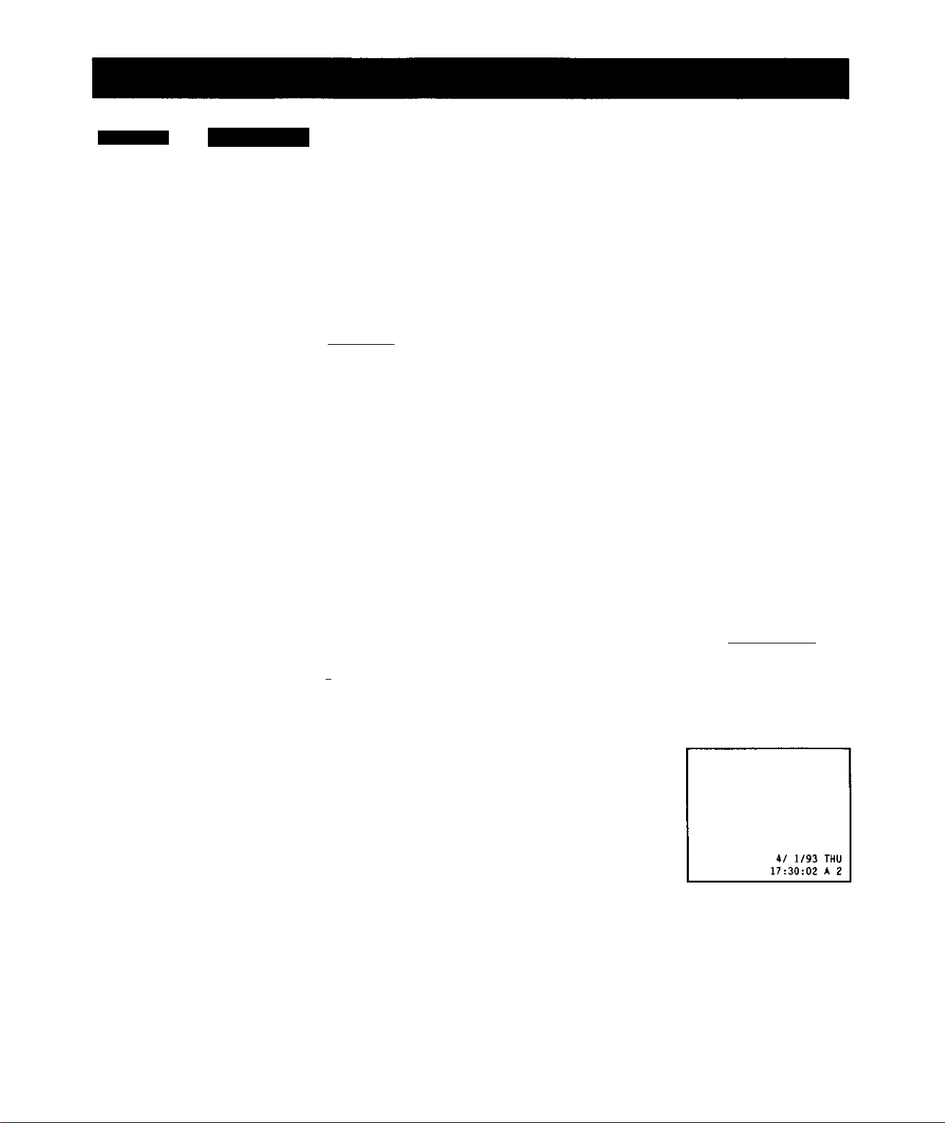
V- ■ » ^ I i»
Art internal time-date generator is provided in this unit for overlapping of date, time etc.
When the power is turned ON for the connected devices and this unit, the date and time modes are dispiayed on the monitor screen
(normal screen).
Operation
For example, when setting to 5:30 PM, Thursday, April 1,1993.
Press the DISPLAY
button.
OtSPlAV SHIFT -SETt
500GD
Press the + SET button.
asPwY SMFT -SET*
IDQUICN S£Cr
□ 0 0 □
Press the + SET button
and set the month to *4“.
DBPUY SUFT -3ET+
O00D5
I CLOCK setI
SETUP
DISPLAY MODE
END-C01SPLAY]
(MONTH) (DAY) (YEAR)
m / 1 / -91
TUE
(TIME) 0:00
MENU-CDISPLAY]
(MONTH) (DAY) (YEAR)
m / 1 / '91
MON
(TIME) 0:00
MENU-CDISPLAY]
Press the ► SHIFT
button to make Time in
hours blink and press the
+ SET button to set to
"17V
OeRAY SMFT -SET*
9B8CT
00505
Press the ► SHIFT
button to make Time in
minutes blink and press
the + SET button to set
to "30".
OSYAY SHFT *SET+
LocitTOfsaar
00505
Press the DISPLAY
button to start display of
8
the set date and time.
DBPtAY SHIT
ulOTicit заест
500DD
______
-Sef4
___ _______
(MONTH) (DAY) (YEAH)
4 / 1 / '93
(TIME) irTtOQ
(MONTH) (DAY) (YEAR)
(TIME) 17:gg
THU
MENU-CDISPLAY]
4 / 1 / '93
THU
MENU-CDISPLAY]
I CLOCK ADJUTTI
SETUP
DISPLAY MODE
PROGRAM
END-CDISPLAY]
Press the *■ SHIFT
button to make Day blink
and press the + SET
button to set to "I*.
nSUY
ЮСАТШ»£СТ
-seT4
□ 0gDg
Press toe ► SHIFT
button to make Year
blink and press the + or
- SET button to set to
"93".
EXSPUY SbIFT -SET+
□ 0 5 D^a
(MONTH) (DAY) (YEAR)
4 /CXI / '91
(TIME) 0:00
(MONTH) (DAY) (YEAR)
(TIME) 0:00
MON
MENU-CDISPLAY]
4 / 1 /
THU
MENU-CDISPLAY]
Press the DISPLAY
button to return to the
normal screen.
CeRAY SHIFT -SETt
usttTioNsaecr
500DD
12
Page 14
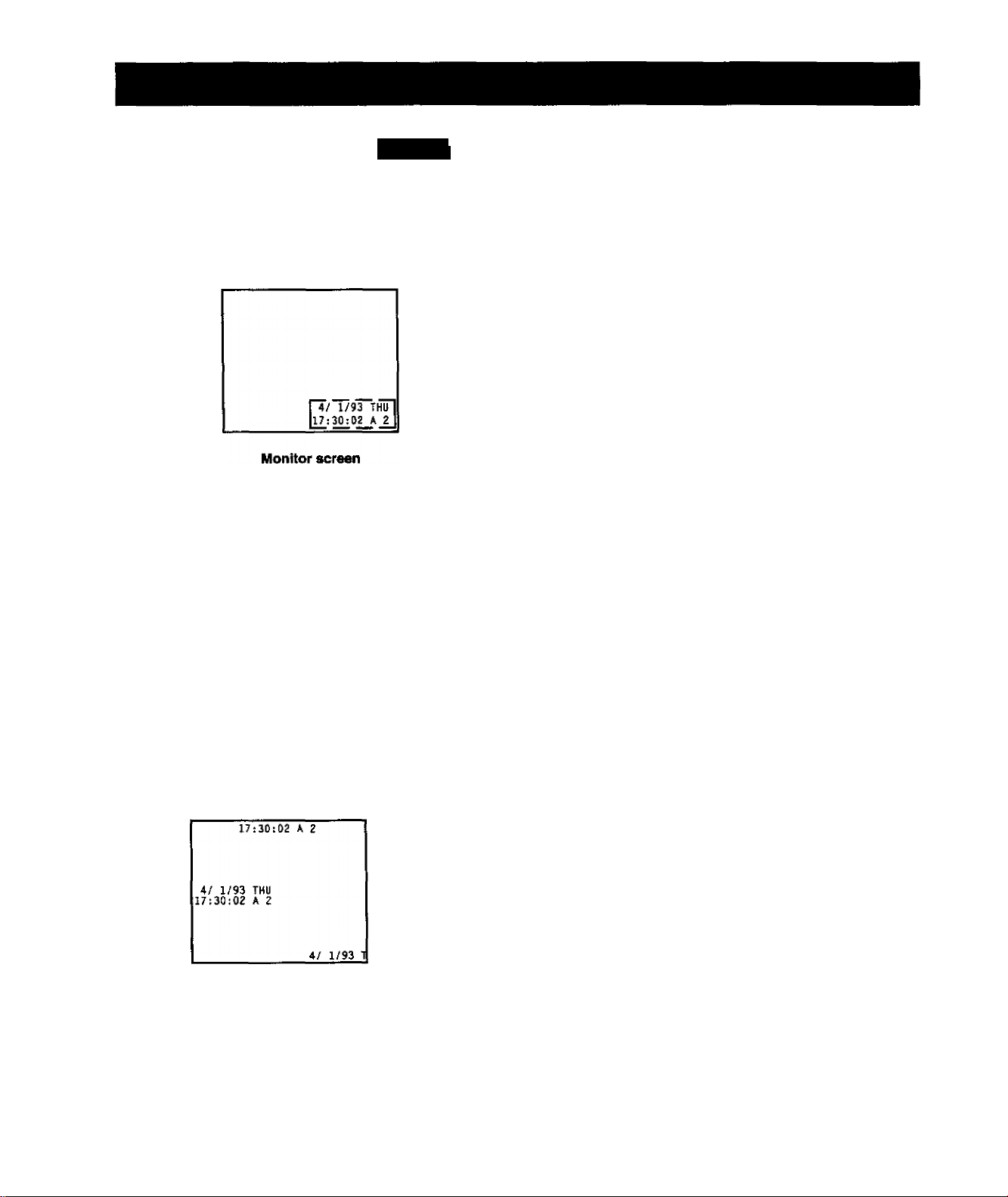
ff. 1
ON-i
With this unit, when the power is turned ON for №e connected devices, the date-time mode display screen is normally displayed on
the monitor screen. This is not displayed when no video input signal is supplied.
■ 4 is r^
Date-Time Display
VCR display
(T) Date
r4/ 1/93 THu"!
[17£30 ^0_2__A_ 2_j
I
©Time
® Date: Displayed with the month-day-year.
<U Day of the week: Automatically set to the correct day of the week when the date is set.
CD Time : Set to 24-hour cycle at factory.
It is possible to modify to 12-hour (AM/PM) cycle display.
® Playback/Recording Time : Playback or Recording time display
On-Screen Position
1 */ 1/93 THU,
r 4 r 1 /9 j THu"! i" 4/” w 93 th"u1
¡17:39:93 A 2i ¡17:30:03 A 2_t
The SHIFT LOCATION SELECT button can be used to move the display posi
tion.
SWFT
oocAiKM safer
a
I
Press this button : To right
Press this button ; To down
@ Day of week
I"'
®
Playback/Recording time
13
The display moves in the direction shown by the arrows.
However, during the date-time display screen, pay attention to the following when
setting the date and time display positions:
When the display is set to an extreme position on the monitor screen as shown in
the figure, synchronization may be disturbed depending on a TV you use. It can
also lead to faulty operation such as flickering of colors.
Page 15

For selection of on-screen display contents and setting VCR number display.
Before operation, set the MENU screen to DISPLAY screen (See page 11.).
Note: ------------------------------------------------------------------------------
Press the DISPLAY button twice to return from the display screen to the monitor screen.
Operation Display Screen
Erasing the date display.
Press the-4 or »> SHIFT button to make DATE blink and
press the + or - SET button to go to OFF.
Changes between OFF and ON
OSPIAY 3HFT
□ BB □ n
-SET+
each time the + or - SET button
is pressed.
T T
Erasing the day of the week display.
Press the-4 or ► SHIFT button to make DAY OF THE WEEK
blink and press the + or - SET button to go to OFF.
Changes between OFF and ON
ceur SHFT
-SET*
each time the SET button is
pressed.
D0^[\D
Erasing the time display.
Press the 4 or ► SHIFT button to make TIME blink and
press the + or - SET button to go to OFF.
Changes between OFF ^d ON
DORAY SHTT -SET+
eadi time the + or - SET button
is pressed.
□ 0^0
(DATE) (offI
{DAY of the WEEK)
(TIME) ON
(SPEED) ON
(VCR) OFF
(ALARM) ON
aZH/24H) 24H
(CHAR,LINES) 6
MENU-[D1SPLAY]
(DATE) ON
(DAY of the WEEK) [ME]
(TIME) OH
(SPEED) ON
(VCR) OFF
(ALARM)
(12K/24H) 24H
(CHAR.LINES) 6
HENU-tDISPLAY]
(DATE) ON
(DAY of the WEEK)
(TIME)
(SPEED)
(VCR) OFF
(ALARM) ON
(I2H/24H) 24K
(CHAR.LINES)
MENU-iDISPLAY]
ON
ON
ON
foFh
ON
Monitor Screen
6
Erasing the speed display.
Press the-4or ¥■ SHIFT button to make SPEED blink and
press the + or - SET button to go to OFF.
Changes between OFF and ON
oeRAY SHFT
UXnKM «IKT
0 0,0
-SETt
each time the + or - SET button
is pressed.
(DATE) ON
(DAY Of the WEEK) OH
(TIME) ON
(SPEED) [off]
(VCR) OFF
(ALARM) OH
(12H/24H) 24H
(CHAR.LINES) E
MENU-CDISPLAY]
14
Page 16

Note: ------------------------------------------------------------------------------------------
Press the DISPLAY button twice to return from the display screen to the monitor screen.
Operation Display Screen
Displaying the VCR number.
Press the ■< or ► SHIFT button to make VCR blink and press
the + or - SET button to set the VCR number.
Changes as shown below each
oepur SHFT
U».D0N SELECT
-$€T +
oa^D^D
time the SET button is pressed.
OFF -) V01 V02 ^ V03 ->
V04 VOS V06 ^ V07 ->
V08 -> OFF
Displaying the number of alarms.
Press the < or ► SHIFT button to make ALARM blink and
press the + or - SET button to go to OFF.
Changes between OFF and ON
OISPWY SHIFT
lOCKTOi SEiea
-SET*
each time the + or - SET button
is pressed. When an alarm is
Input, the day of the week display
changes to the alarm number.
Displaying the hour display.
Press the m or ► SHIFT button to make (12H/24H) blink and
press the + or - SET button to go to 12H.
Changes between 12H and 24H
OSPIAY SHFT
LDCMOlGElfCT
-SET*
each time the + or - SET button
is pressed.
(DATE) ON
(DAY of the WEEK)
(TIME)
(SPEED) ON
(VCR)
(ALARM) ON
(1ZH/Z4H)
(CHAR,LINES)
(DATE) ON
(DAY of the WEEK) ON
(TIME) ON
(SPEED) ON
(VCR) OFF
(ALARM)
(1ZH/24H) Z4H
(CHAR.LIKES) 6
(DATE) ON
(DAY of the MEEK) DN
(TIME) ON
(SPEED) ON
(VCR) OFF
(ALARM) ON
(1ZH/Z4H)
(CHAR.LINES)
MENU-tDlSPLAY]
MENU-[DISPLAY]
HENU-tDISPLAY]
ON
OH
fvoTI
24H
I~0n1
fT^
Monitor Screen
VCR number
6
G
4/ 1/93 THU
17:30:02 A Z
Alarm number
4/ 1/93 AOl
17:30:13 A Z
VOl
I
This function enables to indicate and record Information from
cash register or ATM using optional interface board.
1. Pressthe-4or ► SHIFTbuttontomakeCHAR.LlNES
blink and the + or - SET button to go to "6*.
?. Press the + or - SET button to select the characters of
' line number. Each time pressing the + or - SET button,
thenisplay changes as follows:
• If you selected
[DATE] ON; 1 ^ ^ ^
[TIME] ON: ]
• If you selected
[DATE] OFF: 1 „ , o H o ^ X c
IJIMEIOFF: l6^7->8^1^2^3^4^5
15
(DATE)
(DAY of the MEEK) OH
(TIME)
(SPEED)
(VCR)
(ALARM) OH
(1ZH/Z4H)
(CHAR.LINES)
MENU-CDISPLAY]
ON
DN
ON
OFF
Z4H
oi
Page 17

Counter Memory
When the counter is set to *0000" at a location that you want to see again during recording and playback, the tape will stop in the
vicinity of "0000* during rewind and fast forward.
Set the display to the counter display.
<nnn P p
COUNT. COUNT RESET
MEMORY
COUW. COUNT, RESET
T
Press the BESET button at the location you want to
see.
H
0 3
1 1 L
QOUHT. COUNT. RESET
MEUQFTT
n n n n
► u u u u
Alarm Memory
When you want to view the location where alarm recording was performed.
Press the STOP button.
lALWMl **
r H c*
STOP
Press the COUNT. MEMORY button to make
"COUNT.M" (Counter Memory) to light.
B5I
MEMORY
COUNT. H
r
n n n
f u 1 u
H
If
□ D°
T
Make rewind or fast forward when recording or play
back is finished.
I n n n
t iJ I u
FEW PlAY
FF
i^
Make rewind or fast forward.
IB. isrfsril
I U < U I
RE№ PLAY
11 I ftisrrn r6oorci0cl position^ Th6
When the tape reaches the
alarm recorded position, The
L-y. II II 'M—I VCR automatically enters the
^ ^ Alntll im
still picture mode.
iR C*
' rajinin "
n n n n P p
Press the COUNT. MEMORY button twice to make
h'ress me i. mcmu
alarm memory to light.
2
) ri n n
I I uu
COUNT. COUKT. RESET
MEMORY
M l*u™l
on
) c U
Press the PLAY button.
REYir PlAY
□5°
Note: ------------------------------------------------------------------------------------------------------------------------------------
In order that the Alarm Memory function can operate normally, it is necessary that alarm recording takes place for at least 2 sec
onds in the A2-hour mode. Thus, when the recording for less frian 15 seconds in the A12-hour mode or for less than 30 seconds in
A24-hour mode is performed, the alarm memoiy function iMIl not operate normally. Also, in order to carry out tape search at high
speed, an interval of about 5 seconds is necessary during alarm recording. Otherwise the unit will skip that section during search.
—
16
Page 18

Tape Remain
When the TAPE REMAIN button is depressed during recording or playback, the counter display changes to the remaining tape
display. The remaining time is the approximate time to tape end when operating the unit in the A2-hour mode.
TAPE
n I*
¡H3Ü
• The remaining time is the approximate remaining time.
• Displays the remaining tape time in ttie A2-hour mode.
During computation of the remaining time, the following display appears.
n C
REMAM
ga
(
------
______
1
r
► r
• When ^ unit has been used in the recording mode over a long period, it may take considerable time for computation. When
operating at fast speed in the A2-hour mode, the computation is faster.
H
R г
Nota:----------------------------------------------------------------------------------------------------------------------------------------
it is possible to compute the remaining time forT-120, T-90, T-60 and T-30 tape. The display will not be correct for other kinds of
tape.
Error Message
When an abnoimality occurs during operation, the error code is displayed.
At the same time, a signal is output to the buzzer output terminal.
Condition of Abnormality
£- Í
R Í
Code Number
E-1 Abnormality on reel rotation during tape running.
E-3
E-4 Abnormality on tape loading mechanism.
E-5
E-6
E-8
Abnormality on cylinder rotation during recording and playback.
Video tape is broken.
Video heads are dogged.
Dew condensation.
17
> When the error code "E-1" to "E-4* are displayed, consult with your dealer.
' When the error code "E-5" is displayed, the tape is broken. Replace with a
new tape.
> Regarding the error code "E-6“ Display
When recording in time mode between 48 and 960 hours or in the One-shot
mode, video head clog detection is automatically carried out once for every
three minutes. When the video head dog is found, head cleaning is carried
out for ^proximately 10 times. When cleaning is still not possible. "E-6‘ is
displayed and the RED display blinks on the monitor although recording
continues. In such a case, cleaning of the wdeo heads is required.
Page 19

Before carrying out time lapse recording/playback, it is necessary to set the time mode.
This equipment is designed for use with T-120 video tape as the standard. We therefore recommend use of T-120 video tapes.
TIME MODE button:
Recording/playback time
Consult the fdiowing chart to select a correct time for your purpose.
*
Mode display
Record Available Time
(when using T-120)
A2
2 hours
A 12 14 hours
A 24
26 hours
24 24 hours
48 48 hours
72
120
72 hours 72 hours 0.60 seconds Impossible Intermittent
120 hours 120 hours
168 168 hours
240
240 hours 240 hours
480 480 hours
720 720 hours
960
LOl 1 min.)
, _ (Zftotdf
L02 2 irtn.)
1 rto
960 hours 960 hours
3,600 hours
7,200 hours
10,800 hours
Play Available Time
Recording interval Audio record
(when using T-120)
2 hours 1/60 seconds Possible
14 hours
0.12 seconds Possible Continuous
26 hours 0,21 seconds Possible
24 hours
0.20 seconds Impossible Intermittent
48 hours 0.40 seconds Impossible Intermittent
1.0 seconds
impossible Intermittent
168 hours 1.4 seconds Impossibie
Impossibie Intermittent
480 hours
2.0 seconds
4.0 seconds Impossibie Intermittent
720 hours 6.0 seconds impossible
8.0 seconds
Impossible Intennittent
60 seconds Impossible
120 seconds Impossible Intermittent
180 seconds Impossible Intermittent
Tape running
Continuous
Continuous
Intermittent
Intermittent
Intermittent
*1: Por One-shot recording, set to one of the following time intervals: L01, L02, LOS.
■ The possible recording time depends on the type of video tape used.
• Audio recording is possibie in the A2, A12 and A24 hour modes.
■ The A12, A24, 24,48,72,120,168, 240, 480,720 and 960 hour modes as well as the One-shot recording mode are time
lapse modes.
18
Page 20

’ •
........
*' ■ ’-•Tl
LOADING
Cassette compartment
■fe
Fl V.
2
1
ройся
■â
ПРИ mff FF ЗТОЯ
i<wi > jisoi □ Kim iiHoyii
TIME LAPSE VCR■
4Heai3 t 960Hour
П&.
b
Loading a cassette
Insert a cassette in the Cassette Compartment.
■ Power goes on automatically and the cassette indicator
iights.
TIME LAPSE VCR•
Э
4Head / 960Hour
s
ЩЛ* If угри НИЖУ
|<М| > |М>| □ I <i'
i ■ moni
a
"as*
r^@opË'ÜaDDDOOBBBB"B,n.
■■I I I
Unloading a Cassette
Turn the power ON,
POWER
О
Press the EJECT button.
AEJECT
Cassette Indicator
Bitnks when inserting or removing a cassette.
Remains iighted when a cassette is inserted even if the
power is turned OFF.
Cassette indicator
19
Safety Tab
A video cassette is equipped with a safety tab to prevent
accidentai erasure. When the tab is removed, recording
cannot be performed.
R
H
D
If you wish to record on a cassette with the tab removed,
use adhesive tape to cover the hole.
Ш
_
nn n n
► и и u u
Page 21

Recording operation
Turn on the power for this unit as well as associated
devices of the surveillance system including the video
camera and monitor TV.
Adjust the monitor TV so that the picture from the
video camera is displayed properly.
I.I.ltL
Check that the date time display on the monitor TV is
correctly displayed.
3
A/ 1«3T>^U
Set the various functions such as timer recording,
alarm recording, restart recording, tape end, etc.
2
Insert a video cassette to this unit.
• Check that the safety tab on the video cassette has
not been removed.
Select the recording time mode.
6
thie mcoe
nn n n
u u u u
0§
Press the REC button.
Iñecl
n n n n
>■
REC
U Ü u u
Q
n
R
H
1?
H
г
(9Z
ZO
OH
flC<
8£
zo
Notes:
When ItTB PAUSE button is pressed during recording, the unit goes to the pause mode. To release, press either the PAUSE
button again or the REC button. When the pause mode continues for 10 minutes the unit goes to the stop mode.
Repeat recording, restart recording, alarm recording, etc. also operate during recording.
When the unit is stopped during recording or the recording time is changed, the pictures may be disturbed at that location.
In case of power failure restart recording, if a power failure should occur and it is within approximately 10 days in length, it is
possible to resume recording in the same time mode after power failure is recovered.
During repeat recording, pay attention to the following points.
• Timer recording and alarm recording is not possible during automatic rewind.
■ The buzzer does not sound even at tape end.
• When an operation button is pressed during automatic rewind, the repeat recording function does not operate. Reset to the
recording mode.
The button is not accepted during alarm recording or timer recording.
When carrying out repeat recording or timer recording, be sure to cany out daily checks.
20
Page 22

aMiiiiillMiWiki:''-
Setting the Restart Recording
On the SETUP screen set RESTART RECto ON. If a power failure (10 days or less) occurs, the unit also returns to recording when
the power is recovered.
Press the DISPLAY
button. The MENU
screen appears on the
monitor screen.
CISPLAV SHIFT
LOOlTCIl££Cr
-SET*
ÇQ0DD
Press the or ►
SHIFT button to make
SETUP blink and press
the + or - SET button.
DH«Y 3HFT
-ser+
CLOCK ADJUST
SETUP
DISPLAY MODE
PROGRAM
END-[01SPLAY]
CLOCK ADJUST
I SETUP I
DISPLAY MODE
PROGRAM
□ Q|0
Press the-4 or
SHIFT button to make
RESTART REC blink.
asfw SHFT
UKKTOl SÜJKÏÏ
-SET*
0 0^0 □ □
Press ttie + or - SET
button to go to ON.
MPUY SHFT -SET+
□ 000^
END-[DISPLAY]
S f T U P
ALARM REC TIME iSS
SPEED A ZH
ISHOT REC FIELD IF
INTERVAL O.ZS
RESTART REC OFF
TAPE END MODE STOP
ALARM STOP
MENU-COISPLAY]
S t I IJ
ALARM REC TIME 15S
SPEED A ZH
ISHOT REC FIELD IF
INTERVAL O.ZS
RESTART REC cm
TAPE END MODE STOP
ALARM STOP
MENU-COISPLAY]
21
Note:
When a power failure occurs during recording, the recording is started automatically after ^ power is recovered regardless of
whether ’RESTART REC" is ON or OFF.
When the power is recovered after more than 10 days have passed, the tape remains at the position where It stopped when the
power failure occurred.
Page 23

There are two ways of timer recording.
One is daily recording at the same time and for the same length (daily timer). The other is weekly recording at a certain time and for
a certain length on different days (weekly timer).
■ Witii the weekly timer it is possible to create 1 program for each days of the week.
■ When the weekly timer and daily timer are set to SKIP, recording will not be carried out even when a time is set.
■ The contents of a timer setting are maintained in the event of a power failure if the power failure ends within 10 days.
■ Before setting times, make sure that the present time is correct. (See page 12.)
Setting the Timer Programme
PROGRAM Screen
Monday -
Tuesday -
Wednesday -
Thursday -
Friday -
Saturday ■
Sunday■
Daily -
ON. SKIP displays -
Starting hour display
HON
TUE
MED
THU
FRI
SAT
SUN
OLY
ON
ON
OH
ON
ON
ON
ON
ON
Í
rr
--
-- --
-- --
--
-- --
-- -- —
--
-- -
H:NU-:OItPLAY]pLA'
------
— Starting minute display
r?iir
IZOH
IZOH
IZOH
- — Recording time display
IZOH
IZOH
IZOH
IZOH
Ending hour display
Ending minute di^lay
Daily Timer Recording
For example, when you want to set for a total period of 480 hours for recording starting every day from 8:30 to 17:00;
Press the DISPLAY
button. The MENU
screen appears on the
monitor screen.
tWRAY SH»T
lOCMiCM saEcr
JJ00DD
Press tire 4 or ►
SHIFT button to make
2
. PROGRAM blink.
OrSPUY SMFT -SETt
iDnncHaBfcr
0 0J0 □ □
-8ET+
CLOCK ADJUST
SETUP
DISPLAY MODE
PROGRAM
END-[DISPLAY]
CLOCK ADJUST
SETUP
DISPLAY MODE
I PROGRAM I
ENO-CDISPLAY]
Press the ^ SHIFT
button. The ending
minute blinks.
OSKAY swr
UXAfOlS&ECr
-SET*
□ §0DD
Press the m SHIFT
button to make the
starting time blink.
DCRAY SHTT
UXAT(h9€LECT
-SETf
O§0DD
HON ON -TUE ON -*
MEO ON -THU ON -FRI ON *SAT OH **
SUN ON -OLY ON --
HON ON
TUE ON
NED ON
THU ON
FRt ON
SAT ON
SUN ON
OLY OH Q-* ■
-- 120H
” 120H
-- I20H
-- teOH
-- IZOH
-- IZOH
-- IZOH
□ IZOH
HENU-fOISPLAY]
-- IZOH
-- IZOH
-- IZOH
-- IZOH
-- IZOH
-- IZOH
-- IZOH
MENU-CDISPLAY]
IZOH
!s
Press the + or - SET
button.
OSrtAY SHFT -SET+
LOATOf SELECT
□ 0 0 D^D
■Changes to Program Screen.
ON of the MON line blinks.
HON ioin - TUE ON -WED ON *THU ON --
SAT ON **
FRI ON --
SUN ON "
DLY ON --
-* IZOH
-- IZOH
-- IZOH
-- IZOH
IZOH
-- IZOH
-- IZOH
-- IZOH
MENU-CDISPLAY]
Press the + or - SET
button to set the starting
time to 8 and press the
► SHIFT button.
OmAY SKR -SET+
LOUTOI&ICT
□ 0§D^a
■ The present Ume Is displayed
at first.
MON ON -TUE ON -WED OH -THU OH -•
FRI OH -SAT OH -SUN ON -DLY ON (8)07-*-- -- IZOH
-- IZOH
-- IZOH
-- IZOH
-- IZOH
-- IZOH
------
-- IZOH
-- IZOH
MENU-CDISPLAY]
22
Page 24

Press the + SET button
to set the starting minute
to 30 and press the >■
SHIFT button.
DOKAY SHFT
lOCATQN sata
-SET*
G0§D!J
MOK ON
TUE ON
MED ON
THU ON
FftI ON
SAT ON
SUN ON
DLV ON
IEOH
-- IEOH
-- IEOH
-- IEOH
-- IEOH
-- IEOH
-- IEOH
-- IEOH
HENU-COISPLAY]
11
press the + SET button
to set the ending hour to
8
17 and press the >>
SHIFT button.
osuY evr -SET»
IDCAUCN aaccr
□ 0§D!J
■The Initial starting tima is
displayed.
Press the + SET button
to set the ending minute
9
to 00.
asw SHFT
>SEt+
□ 00DIJ
Press the л TIME
10
MODE button to set to
480.
me MOPE
0^
Eachrtrme pressing the Л TIME MODE button, the
dispiay changes as foliows.
120 -> 168 240 -» 480 720 -> 960 L01 -» L02
L03 -> A2 -> A6 ^ A12 -+ A24 24 48 -> 72 -> 120
Each time pressing tire v TIME MODE button, the display
changes in the reverse direction.
IF A POWER FAILURE SHOULD OCCUR
If a power failure occurs, the PW.FAIL display appears in
the VCR display. To erase this display press one of the
operations buttons.
If the power failure is within 10 days in length, the data in
the date/time timer iMIl remain in the memory (in the
condition that 20 hours continuous charging is performed
in Ihe normal temperature)._______________
HON ON
TUE ON
MEO ON
THU ON
FRI ON
SAT ON
SUN ON
DLY ON
MON ON -- -• IEOH
TUE ON -- •- IEOH
MEO ON -- -- IEOH
THU ON ” -- IEOH
FRI ON -- -- IEOH
SAT ON -- -- IEOH
SUN ON -DLY ON 8
NON ON
TUE ON
NED ON
THU ON
FRI ON
SAT ON
SUN ON
DLY ON
30-»1Ш30 IEOH
MENU-ÍDISPLAY]
30-И7®Щ IEOH
NENU-[OISPLAY]
30-H7:00l480Hl
HENU-COISPLAY]
-- IEOH
IEOH
-- IEOH
-- IEOH
-- IEOH
" IEOH
'• IEOH
-- lEOK
-- IEOH
-- IEOH
-- IEOH
-- IEOH
-- IEOH
-- IEOH
-- IEOH
_____ __
Press the TIMER button.
12
met
I
■ The power goes off and the TIMER display lights in the
VCR display.
■ Recording starts at the time set.
a At the starting time, recording starts wthout the power
going off, if the starting time set has been passed at tiiat
point.
To release the timer mode, press either №e POWER button or
the TIMER button.
Notes:
■ Setting of the recording time can be done anywhere,
a The timer will operate if there is a difference of at least 1
a The accuracy of the time display will vary according to
During the 12 hour display, the display appears as follows.
--------------------------------------------------------
minute between the starting time and ending time,
conditions for use and the environment. Carry out daily
checks and set to the proper time.
HON ON
TUE ON WED ON '
THU OH FRI ON SAT OK SUN ON DLY ON 8
30Ж-* 5
MENU
IEOH
--- IEOH
--- IEOH
--- IEOH
--- IEOH
--- IEOH
--- IEOH
00m 480H
[DISPLAY]
23
Page 25

Weekly Timer Recording
For example, when you want to set lor a total of 720 hours for recording taldng place from 8:00 to 19:00 on weekdays and from 9:00
to 17:00 on Saturday and Sunday.
Press the DISPLAY
button.
KSPIAV SrFT
tDOnCM BfifCT
JjlBEDD
Press the ► SHIFT
button to make PRO
GRAM blink.
DBPIAY SHFT -SET+
lOGUION SElfCr
□ B§DD
Press the + SET button.
oeuY SHIFT -SET«
LiKxTin SlECr
□ BBDIJ
CLOCK ADJUST
SETUP
DISPLAY MODE
PROGRAM
CLOCK ADJUST
SETUP
DISPLAY HOPE
I PROGRAM I
MON ® - TUE ON -MED ON -THU ON --
FRI OH -SAT ON -SUN ON -DLY ON e
END-LDISPLAY]
ENO-[DISPLAY]
-- IZOH
-- IZOH
-- IZOH
-- IZOH
-- IZOH
-- IZOH
-- IZOH
00 480H
30-*17
MENU-EOISPLAY]
Press the + SET button
to set the starting hour to
8 and press the ►
SHIFT button.
aspwv SHFT
-SET+
QBJJDIJ
Press tile + SET button
to set the starting minute
to 00 and press the >
SHIFT button.
UBVX 3HFT
LOCATCN SELfCr
-8ET+
0B§D!J
Press the + SET button
to set the ending hour to
19 and press the ►
SHIFT button.
□SPIAY SHFT
K»13h 9EI.Ea
□ B^DIJ
MON ON [~atl5
TUE ON
WED ON
THU ON
FRI ON
SAT ON
SUN ON
DLY ON
MON ON
TUE ON
MED ON
THU ON
FRI ON
SAT OH
SUN ON
DLY ON
MON ON
TUE ON
MED OH
THU ON
FRI ON
SAT OH
SUN ON
DLY ON
30-* 17
8
MENU-CDISPLAY2
8
--
- *
30-*17 DO
8
HENU-[OISPLAY]
00-*|l9^a0 IZOH
30-* 17:00 480H
MENU-EDISPLAY]
-- 120H
-- IZOH
-- 1£0H
-- 120H
-* IZOH
-- IZOH
-- IZOH
00 480H
-IZOH
--
IZOH
IZOH
IZOH
IZOH
IZOH
IZOH
IZOH
IZOH
Press tire ► SHIFT
button to make the MON
starting time blink.
tMPlAY SHFT *SET +
; 0- 0 ^ □
MON ON Q - TUE ON
MED OH
THU ON
FRI ON
SAT ON
SUN ON
OLY ON
30-*17
8
MENU-CDISPLAY]
-- IZOH
-- IZOH
-- IZOH
-- IZOH
-- IZOH
•- IZOH
-- IZOH
00 480H
Press the + SET button
to set the ending minute
8
to 00.
oerw SHFT
lOCKTIC« B£CT
DBBDIJ
HON ON
TUE ON
MED ON
THU ON
FRI ON
SAT ON
SUN ON
OLY ON
00-* 19:g^ IZOH
-- IZOH
-- IZOH
-- IZOH
-- IZOH
-- IZOH
3017:00 480H
MENU-[OISPLAY]
IZOH
24
Page 26

Press the A TIME
MODE button to set to
720.
TWE UOOE
0 0
T
The ending mirnite of the MON
line blinks.
HON ON
TUE ON
WED ON
THU ON
FRI ON
SAT ON
SUN ON
DLV ON
00-
19:00ÌTIQhI
-- 120H
-- 120H
-- 120H
-- 120H
-- 120H
•• 120H
30-*17:00 480H
MENU-tDISPLAY]
12
Press the ► SHIFT
button to make the On of
DLY blink. Press the +
SET button to set to
SKIP.
OBWY SHFT -SET +
LXDn)CM«£Cr
O0§n!J
MON ON 8:00-* 19:00 720H
TUE OK 8:00-H9:00 720H
WED ON 8;00-> 19:00 720K
THU ON 8:00-> 19:00 720H
FRI ON 8:00-+19:00 720H
SAT OH 9:00-U7:00 720H
SUN ON 9:00-U7;00 720H
DLY [Ш£]8:30-И7:00 480H
HENU-EOISPLAYJ
10
Continue to press the
► SHIFT button to
make the TUE starting
time blink. Repeat steps
5 to 9.
OSnAY SHFT -SETt
LocnoisafCT
DQ§DD
Set to WED, THU, FRI,
SAT and SUN following
tile steps 4 to 10.
bSUY SHTT
-SET«
HON ON 8:00-»19
TUE ON Q--**--
WEO ON
THU ON
FRI ON
SAT OH
SUN ON
DLY ON
MON ON
TUE ON
WED ON
THU OH
FRI OH
SAT OH
SUN OH
Dt-Y OK
30-H7
MENU-CDISPLAY]
00-H9:00 720H
00-* 19:00 720H
00-»I9:00 720H
00-*I9:00 720H
00-H9:Q0 720HI
00-H7:00 720H
00-»17:00 720H
30-»I7:00 480H
MENU-tOISPLAY]
00 720H
-- 120H
-- 120H
-- 120H
-- 120H
-- 120H
-• 120H
00 480H
13
14
Press the DISPLAY
button twice.
OSUV EMFr -EET*
§00DD
Press the TiMER
button.
TIER
M
T
OFF
Overlapping Programs
When the setting times 1 for the day of the week and the daily times overlap, recording will be made as shown below.
Example:
—^ FR!
DLY
Recording
contents
If, as shown below, the timer recording button is pressed after 10:00, FRi is recorded and DLY is not implemented. (The order of
priority for recordings in case of overlapping is FRI, DLY).
Example:
FRI
dly'
Recording
contents
25
8:00 19:00
/ ? ?7///^ /// j ///Т////;////j ////// i ^ j / /
10:00
:00
T7 / J / / / / / /-rrrrrrr/ / J / / / r-n / 7 7 7 / J / / ; / / 7 /
DLY
FRI
19:00
'J
FRI
21:00
DLY
21:00
/
Page 27

It is possible with this unit to carry out One-shot recording to record only when there is a trigger input from outside or for use as a
data fiie. If a trigger is input to the One-shot input on the back, there will be recording for the field numbers set at the time interval
set.
-----------
Connecting the One-shot terminal
-----------------
Example: When setting for a total of four fields at an interval
of 0.5 seconds.
I 4-fieIds recording i
To One-shot in
ToGND
Consult with your dealer about the remote control switch.
Operation of One-shot Recording
Press the A TIME MODE button to select L01, L02 or
L03.
n n n n
u u u u
0 ^
Press the DISPLAY
button.
CLOCK ADJUST
SETUP
DISPLAY KODE
D9UY S№ -m*
LOOtflQN KLECr
JJ00GD
Press the ► SHIFT
butten to make SETUP
blink and press the +
SET button.
MPIAY SMÍT
-SET*
D0IJDIJ
PROGRAM
END-CDISPLAY]
CLOCK ADJUST
I SETUP I
DISPLAY MODE
PROGRAM
END-CDISPLAY]
I n i
!_ U I
U LT U
O.Ssec
one field recording
Press the ► SHIFT button to make 1 SHOT REC
FIELD blink and press the + SET button to set the
X
number of recording fields.
ALAlUt REC TIME
ISHDT REC FIELD
l»fUiY SHIFT
lOOTKM SELECT
-SET+
RESTART REC OFF
TAPE END MODE STOP
O0§G!J
Each time pressing the + SET button the display changes
as follows.
1F-> 2F-> 4F ^ 8F16F32F-) MANUAL
Each time pressing the - SET button, the display changes
in the reverse direction.
Display Recording fields
IF 1 field
2F 2 fields
4F 4 fields
8F 8 fields
16F
32F
MANUAL
16f ields
32 fields
Accepting the oneshot input.
SPEED A ZH
INTERVAL o.zs
ALARM STOP
NENU-CDISPLAY]
15S
I ItJ
Note:
Because the head is constantly tracing the same location, it can cause damage to the head and tape. For this reason, if there is
no One-shot input when the time mode is set to L01, L02 or L03 the unit automatically records 2 fields every 1, 2 or 3 minutes to
protect the tape and heads. Choose the time mode suited to your particular purpose.
26
Page 28

Press the ► SHIFT button to make INTERVAL blink.
Press the + SET button to set the time interval be
tween the individual recording fields.
tWRAV SHTT
kOOinON SElKT
ALARM REC TIME 15S
ISHOT REC FIELD IT
RESTART REC OFF
TAPE END MODE STOP
SPEED A ZH
INTERVAL ID. ESI
ALARM STOP
□ 0§D!J
MENU-CDISPLAY]
Each time pressing the + SET button, the display changes
as follows.
0.2s —^ 0.5s —^ 1.0s 2-Os
Each time pressing the - SET button, the display changes
in the reverse order.
Display
0.2s
0.5s
1.0s
2.0s
Time interval
1 field per 0.2 seconds
1 field per 0.5 seconds
1 field per 1,0 seconds
1 field per 2.0 seconds
Press the REC button.
Input from the remote control switch.
8
tl
Remote control swritch
To release the One-shot Recording mode
Press the V or A TIME MODE button to change the time display on tire VCR display to a display other than L01, L02 and L03.
Note:
One-shot input is not accepted during recording pause.
27
Page 29

If an abnormality occurs during a long period of recording, the alarm function operates.
Operation at Alarm Input
When there is an alarm input during recording, recording pause or stop, the unit changes to the set time mode (A2, A12, A24 hours)
and carries out detailed recording of the abnormality during the set time period.
Alarm input
Recording
Recording pause
Stop
Recording
Recording pause
Stop
Alans Recording
Warning at Alarm Recording
Whan an alarm signal is input, the buzzer sounds and the alarm display on the VCR display lights.
Alarm disptay lights and then blinks when
alamt recording is finished.
The day of the week display
changes to the alarm number
dudng alarm recording.
Changes to a display of A2,
At 2 or A24.
Turn off the BUZZER switch to stop the buzzer.
To make the alarm display stop blinking, press the COUNT, button to change the counter display to the alarm counter and then
press the RESET button.
Changes to a display of A2,
Ai2orA24.
28
Page 30

Connecting the Alarm Terminals
Connecting the ALARM IN/OUT terminals
• When the alarm switch Is ON, an alarm recoiling starts. It is possible to confirm the warning from outside by connecting a
lamp or a buzzer to the alarm output.
Connecting alarm reset input
Alarm reset switch
> When the alarm switch is ON, the alarm recording starts. However, when the alarm reset switch is turned ON after starting, the
al^m recording is released and the unit returns to the original condition of time-lapse recording.
Note:
When simultaneously connecting alarm input and alarm reset input, be sure to carefully check the voltage levels of them.
29
Page 31

I Setting the Alarm Recording
Press ttie DISPLAY
button.
CLOCK ADJUST
SETUP
DISPLAY MODE
tmny SHIFT -sETt
LfODCN ai£CT
§Q0GD
Press the ► SHIFT
button to make SETUP
blink and press the +
SET button.
DSFIAY SHFT -S6Tt
□ 0§D!}
Press the + SET button to set the alarm recording
time.
DGFUY EHFT
-SETt
□ 00D!J
Pressing the -t- SET button changes the display as follows.
15S -> 308 -> 1MOOS -> 1M30S 2M00S 2M30S
3M00S ^ 6M00S CONT. -> MANUAL -> 5S 15S
Each time pressing the - SET button changes the display
in the reverse direction.
Display
5S
15S
30S
1M00S
1M30S
2M00S
2M30S
3M00S
6M00S
CONT.
MANUAL
__
Recording time
5 seconds recording
15 seconds recording
30 seconds recording
1 minute recording
1 minute and 30 seconds recording
2 hours recoding
2 minutes and 30 seconds recording
3 minutes recording
6 minutes recording
Recording to tape end
Recording during alarm input
PROGRAM
END-[01SPLAY]
CLOCK ADJUST
ISETUM
DISPLAY MODE
PROGRAM
END-tDISPLAY]
ALAWI REC TIME I 15SL
SPEED A ZH
ISHOT REC FIELD IF
INTERVAL 0.2S
RESTART REC OFF
TAPE END MODE STOP
ALARM STOP
MEHU-CDISPLAY]
Press the ► SHIFT button to make SPEED blink and
press the + SET button to set the recording time mode.
ALARM REC TIME ISS
ISHOT REC FIELD IF
aspiAY SHIFT
-8ET+
RESTART REC OFF
TAPE END MODE STOP
D0§G!J
Each time pressing the + SET button, the display changes
as follows.
A2H -> A12H -»A24H -> A2H
Each time pressing the - SET button, the display changes
in the reverse order.
Press the ► SHIFT button to make TAPE END
ALARM blink and press the + SET button to set
operation after detection of tape end.
ALARM REC TIME 15S
ISHOT REC FIELD
Deuw SHTT
-ser+
RESTART REC
TAPE END MODE STOP
□ 0§G!J
Each time pressing the + SET button the display changes
as follows.
STOP -Y CONT.
STOP.... Stops at tape end when alarm recording is set.
CONT ... Performs an operation when tape end is detected.
Press the DISPLAY
button twice to erase №e
6
display.
DBPIAY SHTT
UXAT)ONSa£Cr
-SET 4-
0BGG
SPEED ITTHI
INTERVAL 0.2S
ALARM STOP
MENU-COISPLAY]
SPEED A 2H
INTERVAL
ALARM
MENU-CDISPLAY]
Istori
4/ 1/93 THU
17:30:02 A 2
IF
o.zs
DFF
30
Page 32

Operations that will be made after tape reaches its end can be selected as follows.
How to Set
Press the DISPLAY
button.
OBW SHFT
IttAttN S
-S£T +
^GBGG
Press the or ►
SHIFT button to make
SETUP blink and press
the -I- SET button.
¡»MAY SHFT
UOttOlS&ECr
-SCT +
□ 0^G!J
Press the -1 or »•
SHIFT button to make
TAPE END MODE blink.
OtiRAY SHFT -ЖТ+
□ G G
CLOCK ADJUST
SETUP
DISPLAY MODE
PROGRAM
ENO-tOISPLAY]
CLOCK ADJUST
I SETUP I
DISPLAY MODE
PROGRAM
EN0-[01 SPLAY]
ALARM REC TIME
SPEED A 2H
ISHOT REC FIELD
INTERVAL 0.2S
RESTART REC
TAPE END MODE IstopI
ALARM
MENU-[DISPLAY]
ISS
IF
OFF
STOP
Press the + or - SET
button to set the opera
tion after detection of
tape end.
OCPIAY ЗНГГ
lOOtTOhSElfCr
О00Р|Р
ALARM REC TIME 15S
SPEED A 2tt
ISHOT REC FIELD IF
INTERVAL 0.2S
RESTART REC OFF
TAPE END MODE ISTOPI
ALARM STOP
MENU-t01SPLAY]
Each time pressing the + SET button, the display changes
as follows.
STOP (REW STOP) (REW -> REC)
t
___________________________
I
Each time pressing the - SET button, the display changes
in the reverse order.
Display
STOP
Operation after detection of tape end
Stops at tape end.
REW STOP Rewinds to beginning of tape and stops.
REW REC
Set to carry out repeat recording.
Rewinds to beginning of tape and records.
31
Note:'
The^uzzer, screen display and counter displays operate as follows depending on the setting for operations after detection of
the tape end.
Setting contents
STOP
REW ^ STOP
REW ^ REC
Buzzer sounds at tape end
Buzzer sounds at tape end
_____------
Buzzer
Screen display
TAPE END blinks
TAPE END blinks
Counter display
Counter display blinks
Counter display blinks
_____
-------
---
Page 33

The auto rewind function operates at tape end in the recording. This is heipful to keep the tape recorded.
How to Set
Press the DISPLAY
button.
□BUY SHFT -ser^
LOdcTOiKLOlT _____ ____
^0000
Press the 4 or ^
SHIFT button to make
SETUP blink and press
the SET button.
OSUY SHFT
iO»fOlKl£Cr
-set*
□
Press the 4 or ►
SHIFT button to make
TAPE END MODE blink.
DSPIAY SHFT -SET+
□ B.J.0 □ □
CLOCK ADJUST
SETUP
DISPLAY KODE
PROGRAM
END-[DISPLAY]
CLOCK ADJUST
iSETUP!
DISPLAY MODE
PROGRAM
END-CDISPUY]
ALARM REC TIME 15S
SPEED A 2H
ISHOT REC FIELD IF
INTERVAL D.2S
RESTART REC OFF
TAPE END MODE i?TOP]
ALARM STOP
MENU-CDISPLAY]
Press the + or - SET
button to select REW
STOP.
EXSPIAY SHFT
LOunwSUCT
-SCT+
□ 0 0 D^D
ALARM REC TIME 15S
SPEED A 2H
ISHOT REC FIELD IF
INTERVAL O.ZS
RESTART REC OFF
TAPE END MODE lREW-»STOPi
ALARM STOP
MENU-CDISPUY]
Press №e DISPLAY
button twice to erase the
dispiay.
OBPIAY SMFT
LDCADOHI&ECT
-SET*
^00GD
When tape end is detected during recording, the tape
automatically rewinds and stops at beginning of tiie tape.
Note:
AtaTm recording does not operate during auto-rewind.
32
Page 34

When the tape end is detected, the repeat function operates. The unit automatically rewinds the tape and repeats recording.
How to Set
Press the DISPLAY
button.
aaw SHFT
LOCfi?Ol££Ct
-SET*
^00DD
Press №ie •« or ►
SHIFT button to make
SETUP blink and press
the + SET button.
oeviY SHIT
LOCJiloiaucT
Press the •< or »■
SHIFT butt<»Y to make
TAPE END MODE blink.
cBPur SHFT
0 0^0 □ □
-SET*
■ « MENU • I
CLOCK ADJUST
SETUP
DISPLAY MODE
PROGRAM
EHD-[01SPLAY]
CLOCK ADJUST
I SETUP!
DISPLAY MODE
PROGRAM
END-[DISPLAY]
ALARM REC TIME 15S
SPEED A ZH
ISHOT REC FIELD IF
INTERVAL O.ZS
RESTART REC OFF
TAPE END MODE ISTOpI
ALARM STOP
MENU-[DISPLAY]
jm Press the + or - SET
button to select REW
ALAiat REC TIME 15S
REC. SPEED A ZH
cepiAY sH«T -ser+
□ 000^
■ Now the Repeat Recording Setting
is completed.
ISHOT REC FIELD IF
INTERVAL O.ZS
RESTART REC OFF
TAPE END MODE IRE«-*ST0PI
AURM STOP
MENU-[DISPLAY]
Press the DISPLAY
button twice to erase the
display.
OSAAY SHFT
^0BDD
-SETt
4/ 1/93 THU
17:30:02 A 2
When tape end is detected during recording, the unit
automatically rewnds the tape and goes to recording state
at beginning of the tape.
Notesj^-----------------------------------------------------------------------
« When carrying out repeat recording, be sure to carry out daily checks.
u Alarm recording does not operate during auto-rewind.
33
Page 35

An external sequential switcher can be used with this unit for recording.
Connection with the Sequential Switcher
For detailed operations and connections of the switcher consult the instruction Manual of the sequential switcher.
When using the sequent!^ switcher for 4 channels (and recording for 72 hours)
1^
Sui
Sa
icO
Each time a video track is recorded, the camera is automatically switched by ttie position of the vertical synchronization
signal.
The camera switching time differs according to the time mode.
34
Page 36

Playback operation
IgLAYiXgll
Turn the power ON for the monitor TV.
Press the PLAY button.
REW F\AY FF
l<M| > IM>
Insert a tape which has been recorded on.
'TIME LAPSE VCR-
UHd t 9«0Hour
Select the playback time mode.
me MODE
0^
Tracking Adjustment
Use the V , A TRACKING button to adjust when noise appears on the playback screen.
^ ^ nnn n
► u u u u
H
o
t f
г
Press e№er v or a TRACKING button so that a
TTWCKMQ
0 0
dearer picture is obtained.
When returning the tracking to a standard adjustment
value, press a and v buttons simultaneously.
Hotesi
When restart recording is ON and a power failure occurs or the power cord has been removed and replaced, this unit will
automatically go to the recording mode.
When the PAUSE button is pressed during playback, the unit will carry cut still playback. To release, press the PAUSE or PLAY
button again. When still screen playback continues for more than 10 minutes the unit goes to playbadt mode.
Reverse playback is released after 1 minute and the unit returns to normal playback.
The time mode cannot be changed during reverse playback (only in A2-hour),
When playing back a tape that has been recorded in a time-lapse mode (A12-960 hours), pay attention to the following points.
• There wilt be some horizontal picture unstable, but this is not wrong with the unit.
• The upper section of the picture on the monitor screen may be distorted. This is not an abnormality.
When playing back tapes recorded in the various time modes, the picture may wobble somewhat depending on the time mode.
Recording time mode
A2 hours, A12-960-hours
The vertical picture unstable occurs during playback in the A12- and A24-hour modes. This is not an abnormality.
When returning to normal playback after picture search, the picture may wobble.
Time mode for playback
A2 hours, A12-960-hours
35
Page 37

■ 1},:
The following operations are carried out during playback.
Picture Search
Possible to carry out fast forward and rewind while viewing
picture and thus quickly locate the section you wish to view
(played back at 5 times the speed in the 2-hour mode).
Press the REW or FF button during playback.
PtAV
«I > lM> l
Press the PLAY button to return to playback.
Slow Playback
Used for creating a clear playback in the time-lapse mode of a
recorded tape.
Press the TIME MODE button during playback to set to one of
the times {A12-960}.
TME UOK
00
To return to normal playback, press the button to set to A2
hours.
Reverse Playback
Used to carry out reverse playback of tapes recorded in the
time-lapse mode.
Press tile R.PLAY button during playback.
rlpluv pause
L<_L^
Still Playback
Used to take a photograph, for example, of a particular scene.
Press the PAUSE button during playback.
O
To return to playback, press either the PAUSE button or the
PLAY button.
m If still playback continues for ten minutes, the unit auto-
maticaliy returns to playback.
Field Advance Playback
Used when you want to analyze a scene in more details
during playback.
Press the FF button during still playback.
REW PtAY
l<Ml > IM>
a Each time pressing the button, one field will be forwarded.
To return to playback, press either the PAUSE button or the
PLAY button.
Reverse Field Advance Playback
Used when you want to analyze a scene in more details
during playback.
Press the REW button during still playback.
REW
|<KI|| > I»
To return to playback, press the PLAY button.
■ When reverse playback continues for one minute, the unit
automatically returns to playback.
/Votes:
If the screen waves up and down during still playback,
---------------------------------------------
a Press the TRACKING button in a still playback and adjust
to a position where tite screen waving stops.
TRACKINa
0 0
a Each time pressing the button, one tield is fed in reverse
direction,
a The fieid advance is allowed up to 255 fields.
To return to playback, press either the PAUSE button or the
PLAY button.
If noise occurs during slow playback or still playback,
a Set the slow playback mode and press the TRACKING
button to adjust the tracking.
There may still be some residue of noise even after
traddng adjustment.
36
Page 38

Notice
. i'-A., j ^,!
InputfOutput Terminal Signal tevel
ALARM IN
2Q0m3 or grsiUr
ALARM RESET
200ms or greater
ALARM Oirr
ONE SHOT IN
200ms or greater
5V
REC TRIGG. OUT
33«r&
5V
Output Impedance
220Ohm: MAX 10mA
Output impedtmce
220 Ohm : MAX 10mA
Additional remarks
Ground input 0V-0.5V
Ground input 0V-0.5V
High output (alarm recording)
Ground Input
(During tlme4apM and Orte shot
recording)
2.hour mode, alarm recordng
(2H0;0V)
37
Page 39

This unit has been designed to stand the use over long periods. Nevertheless, we recommend you to carry out regular daily
inspection to insure problem-free use.
Note: -------------------------------------------------------------------------------------------------------------------------------
It is particularly important to carry out daily checks when using the unit for repeat recording.
Order of Daily Checks
Turn the power ON for this unit and for the connected
devices in the surveillance system irtcluding the video
camera and monitor TV.
Does the corect picture appear in the monitor TV?
Is the date-time di^lay correct on the monitor TV?
Press the PLAY button.
HEW PlAY FF
«il > |M>I
Is the playback picture normal?
is there anytiiing abnormal about the recorded date
and time?
Press the REC button.
-
3
Rewind the t^e several digits on the section you
recorded the previous day.
REW-^- PLAY FF
«I > I»
Press the V or ^ TIME MODE button to go to the
A2-hour mode.
1551
n n n n
TME MÖGE
Ç 0
U U Ü u
8
REC
iol
Check the playback picture that was recorded in the 2hour mode.
After checicng these matters change to the mode you
H
z>
Q
c
10
want to set to.
38
Page 40

Steps to Take after Daily Checks
If an abnormality is found, turn the power switch to OFF and remove the power plug from the household AC outlet. Then consult
with your dealer.
A Request for Periodic Checks
This unit includes a time gauge to display the total usage
time. When the HOUR METER button is pressed the total
usage time is displayed for 5 seconds. After this, the time
since the last maintenance is displayed for 5 seconds.
Periodically make sure the usage time.
lool
o
Tota) usage Urne (Eicample: 170 hours)
n n in
U U 1 1
1551
1 n n n
i_ (J LJ 1
Time since the last maintenance (Example: 70 hours)
Regularly clean and replace parts in this unit using the
displayed usage times as a guide.
For further details, consult your dealer.
Tape Usage Frequency
Replace tapes using the chart below as a guide.
Recording time mode
2 hours
12 hours 40
24 hours
48 hours
72 hours
120 hours
168 hours
240 hours
480 hours
720 hours
960 hours
L01 - L03
Usage frequency
100
20
10
7
4
3
2
1
1
1
1
H
Q
D
n
(_
H
HD(_
39
Page 41

Dew Condensation
This unit includes a safety function to prevent operation when dew condensation occurs and thus protects against damage to tapes,
the video heads and other parts.
K condensation occurs
The dew display blinks oh the VCR display and
a buzzer sounds continualiy (when BUZZER
switch is ON).
* To turn the buzzer off, turn the BUZZER
switch to OFF.
-f-
Remove the cassette tape.
♦
What is condensation?
If you pour cold beer in a glass, water droplets gather on
the surface of the glass. This phenomenon is known as
condensation.
W|ien condensation occurs.
It you continue to use the video device in this state, the
tape withcling to the internal parts of the video, causing
damage to the tape and video heads.
Times when condensation occurs.
• When the video device has bean suddenly transferred
from a cold place to a warm place.
• When using the device in a room where the heating has
just been turned on or exposed directly to the cold air
from an air conditioner.
When the device is suddenly transported from an airconditioned room or vehicle to a place with high tempera
ture and humidity in summer.
• When used in a room with high humidity where steam is
rising, for example.
With the POWER switch ON, wait until the Dew
display stops blinking.
This may take several hours depending on
surrounding conditions.
A heater to prevent condensation will not immediately
operate even though the plug is inserted to the AC
outlet
The heater to prevent condensation will not cause the
water to evaporate even though frie plug is inserted to the
AC outlet. When the unit is transferred from a cold place to
a warm place it is easy for condensation to develop in the
video unit. In such cases, insert the plug to the AC outlet
and wait 1-2 hours before using the unit.
40
Page 42

s 4 4
it H ï
If you suspect a breakdown, check the following points before calling your serviceman for follow-up service.
Installation
Power does not go ON.
There is no camera picUtre.
The camera picture is indistinct.
■ Is the power plug securely inserted to an AC outlet?
■ is the unit properly connected to IheTV, video camera and other
devices?
■ Is there any problem with the connection of the connecting cords?
■ Is the camera properly focused?
Function/Operation
■ Has a video tape been inserted?
The unit does not operate even when the control
buttons are pressed.
The clock does not run after restoration of power
following a power failure.
The buzzer does not sound.
a Is the MODE LOCK switch OFF?
a Is the Dew lamp blinking?
The unit is not operating because the safety functions are operat
ing. Wait until the blinking st(^s.
a Has the unit's power plug been removed from the AC outlet for a
long period?lnsert the power plug in the AC outlet and carry out
continuous charging for 20 hours or longer.
a is the BUZZER switch set to OFF? If off, the buzzer does not work.
Recording
Playback, fast fonward and rewind are possible but
recording is not possible.
Recording has stopped.
Nothing Is being recorded.
Not possible to record after restoring power following
a power failure.
.. Repeat recording is not possible. a Is TAPE END MODE on REW-REC?
Timer recording is not possible.
Alarm recording is not possible. a Are the alarm sensor and the alarm input properly connected?
One-shot recording is not possible.
a Is tiie tab on the video cassette broken off?
a Is the video tape at tape end?
a Have more than 10 minutes passed since pressing tiie PAUSE
button during recording?
a Have you been carrying out regular daily checks?
a Is E-6 lit?
If this phenomenon occurs often, something may be broken.
Consult with your dealer.
a Is restart recording OFF?
a Has the power failure lasted for longer than 10 days?
a Has one of the operations buttons been pressed during automatic
rewind?
a Is TAPE END ALARM on CONT?
a Is the present time setting corect?
a Is the timer setting correct?
a Has the TIMER button been pressed?
a Did a power failure continue for a long period after the timer was
set?
a Has the POWER switch been turned ON?
a Has the power plug been removed from №e AC outlet?
a Is the speed on L01, L02, or L03?
a Is the unit set to recording pause? If set to the pause mode, the
one-shot recording does not operate.
41
Page 43

Playback
There are noises in the playback picture.
The playback picture is not clear.
The time-lapse mode playback picture or still
playback shakes up and down.
Two recorded sections appear in the playback
picture when using several video cameras and
changing cameras.
When the unit power plug is inserted to the AC
outlet, recording starts and playback is not possible.
■ Adjust with the TRACKING button.
■ The video head may be dogged or worn out
Consult with your dealer.
■ Press the TRACKING button in a still playback mode and adjust.
M Are you using an external synchronous or gen-lock synchronous
video camera?
Consult with your dealer.
■ Is restart recording set to ON?
Other matters
No screen display appears.
Recording does not continue automatically after
restoring power following a power failure.
■ Has DISPLAY MODE been set?
■ Is the On-Screen position correct?
■ Did the power failure continue for more than 10 days?
Caution:
Do not install the VCR in a location near heat sources, such as radiators or air ducts, or in a place subject to direct sunlight,
excessive dust, mechanical \nbrations or impacts.
Ailow adequate air circulation to prevent internal heat buiid-up. Do not place the VCR on soft surfaces (rugs, blankets, etc.), too
near materials such as curtains and draperies or in a built-in installation such as a bookcase or rack.
Keep the VCR and the video cassettes away from strong magnetic fields.
To disconnect the lead, pull it out by the plug. Never pull №e lead itself.
Do not drop any inflammable or metallic objects, or liquid into the VCR. This may cause damage to the unit.
Do not hit or shake the unit when moving it. This may cause damage.
Remove the cassette from the VCR when not in use.
Save the original carton and packing materials; they will come in handy if you ever have to transport your VCR.
For maximum protections, repack the unit as it was originally packed at the factory.
Do not use volatile liquids such as insect spray near the unit.
Do not leave rubber or plastic products touching the unit for a long time. They will damage the finish.
42
Page 44

Power supply
Power consumption
External dimensions 430mm X 88mm x 354mm (W x H x D)
Weight
Signal system
Recording System
Cassette VHS marked, 1/2 inch cassette tape
Tape speed A2-hour mode; 33.35mm/second
Recording/playback time
Fast forward/rewind time Witf^in 5.5 minutes (when T-120 is used)
Video input (BNC)
Video output (BNC)
Horizontal resolution
Video S/N
Audio input
Audio output -6 dès, less than 47k ohms, pin jack
No. of audio tracks
Audio frequency characteristics
Audio S/N More than 43 dB (2-hour mode)
Operating conditions Temperature: 41 "F to 104“F (SX to 40“C)
Storage conditions -4-’F to 140"F (-20“C to 60"C)
' Connector section
Alarm input ^
Alarm reset input Ground input: 0 to 0,5V
Alarm output DC +5V, impedance; 220 ohm, less than 10mA
One shot input Ground input: 0 to 0.5V
Recording trigger output During time lapse: 0/5V negative pulse signal (pulse width: 33ms)
120VAC, 60Hz
26W
Approx. 7 kg ,t
Standard NTSC color television system
Rotary 2-head azimuth
A2/A12/A24/24/48/72/120/168/240/480/720/960 hours (when T-120 is used)
1 .OVp-p, 75 ohms Unbalanced Luminance signal
1 jDVp-p, 75 ohms Unbalanced Luminance signal
350 lines (monochrome mode), 300 lines (color mode)
More than 45 dB'(2-hour mode);jnonochrome mode
More than 43 dB (2-hour moder)| eoldr mode
Line input: 308mV (RMS) (-8 dBs), more than 47k ohm, pin jack
Microphone input; -70 dBs, less than 5k ohms, M6 jack
1 track
100 Hz to 10 kHz {2-hd’ur mode)
Humidity: less than 80%
Ground input: 0 to 0,5V
2-hour mode: OV
except above-mentioned: 5V
Pesign and specifications are subject to change without notice.
TOSHIBA AMERICA C.P.INC.
CCTV GROUP
VIDEO COMMUNICATION & INFORMATION
SYSTEM DIVISION
82 Totowa Road
Wayne, New Jersey 07470
(201) 628-8000 Ext. 2288
Printed in Japan
70971464
 Loading...