

Toshiba KV-5124A User Manual
TOSHIBA
Instruction Manual
TIME LAPSE VCR
KV-5124A

CAUTlOhí
RISK OF ELECTRIC SHOCK I
DO NOT ore» 1
A
The lightning flash with arrowhead symbol, within an
equilateral triangle, is intended to alert the user to the
presence of uninsulated "dangerous voltage" within the
product's enclosure that may be of sufficient magnitude to
constitute a risk of electric shock to persons.
CAUTIONi TO REDUCE THE RISK OF
ELECTRIC SHOCK, DO NOT REMOVE
COVER (OR BACK). NO USER SERVICE
ABLE PARTS INSIDE REFER SERVICING
TO QUALIFlEp SERVICE PERSONNEL.
WARNING; TO REDUCE THE RISK OF FIRE OR ELECTRIC SHOCK, DO NOT EXPOSE THIS APPLIANCE
TO RAIN OR MOISTURE, DANGEROUS HIGH VOLTAGES ARE PRESENT INSIDE THE
ENCLOSURE, DO NOT OPEN THE CABINET. REFER SERVICING TO QUALIFIED PERSON
NEL ONLY,
NOTE: This equipment has been tested and found to comply with the limits for a Class A digital device,
pursuant to Part 15 of the FCC Rules, These limits are designed to provide reasonable protec
tion against harmful Interference when the equipment is operated in a commercial environment.
This equipment generates, uses, and can radiate radio frequency energy and. If not installed
and used In accordance with the instruction manual, may cause harmful interference to radio
communications.
Operation of this equipment in a residential area is likely to cause harmful Interference in wtilch
case the user will be required to correct the Interference at his own expense.
in the spaces provided below, record the Model and Serial No. located at the rear of your video cassette
recorder.
Model No.
Retain this information for future reference.
The exclamation point within an equilateral triangle is intend
ed to alert the user to the presence of important operating
and maintenance (servicing) instructions in the literature ac
companying the appliance.
Serial No.
Important Precautions
Only cassettes marked NWS can be used with the VCR.
Save Original Packing Materiais
The original shipping carton and packing materials will come in handy if you ever have to ship your VCR. For maximum
protection, repack the set as it was originally packed at the factory.
Surface Damage
This VCR is covered with a clear plastic, to protect the top cover surface during shipping and handling. Daily wear may
result in dents or cracks in the plastic which appear as white marks or other kinds of apparent surface damage. This does
not mean that your VCR itself is damaged. If damage to this coating is extensive, simply peel it off.
Moisture Condensation
Never operate this unit immediately after moving it from a cold location to a warm location, V\/hen the VCR is exposed to
such a change in temperature, moisture may condense on the cylinder inside it, one of its most crucial internal parts. The
unit is equipped with an automatic moisture condensation prevention circuit designed to cope with this problem. It takes
about TWO HOURS for this circuit to work with the power cord plugged in. Please do not use the VCR during this time.
Dally Maintenance
Before beginning the day's operation, rewind the cassette tape recorded on the previous day a few counts and play it back
to check for proper recording.
This VCR is not compatible with ordinary [Vhsi VCRs.
Copyright
To record video tapes and other material only in the event that third party copyrights and other rights are not violated.

Features
This VCR Time Lapse Recorder features recording for 2, 12, 24 hours with audio using T-120 cassette. This recorder employs
2 heads which have the same azimuth to allow slow playback and still playback. It also features various playback functions,
such as picture search, and reverse picture search.
• REAL TIME MODE
Recordings may be made in the 2 hour real time mode.
• TIME LAPSE MODE
Recordings may be made in speeds of 12, 24 hours using
a T'120 cassette.
• NOISE FREE STILL PLAYBACK
The use of a 2-head having the same azimuth mechanism
provides clear, noise free still playback. However, if a tape
recorded in 2-hour record mode is played back, noise may
appear slightly in the upper and lower part of the screen.
• TIME DATE GENERATOR
The built-in time date generator superimposes the Month,
Day, Year, Day of Week, Hour, Minute, Second, Mode, and
Alarm input time on the picture. It may be positioned to avoid
interfering with critical areas of the picture. A battery backup
protects the program memory against power failures for up
to 7 days.
• ALARM RECORDING
An alarm input may be set to activate the 2-hour record
mode for 15 secorids, 30 seconds, or 3 minutes.
• ALARM MEMORY
The starting position of alarm recordings may be
automatically located by using the ALARM MEMORY mode.
Once the position is located, this VCR enters the PLAY mode
in PAUSE for immediate viewing.
• RECORD MODE LOCK
A REC LOCK/RESTART switch is provided to prevent
unauthorized use of the recorder.
POWER FAILURE RESTART
With the REC LOCK/RESTART switch in the ON position this
VCR will automatically return to the record mode selected
prior to a power failure.
SELECTIBLE AUTO REPEAT RECORDING
This VCR may be placed into a repeat recording mode so
that when the tape reaches the end it wilt be rewound
automatically and recording resumed.
PROGRAMMABLE TIMER RECORDING
This VCR can be programmed for 15 programs in total for
timer recording: two programs per day plus one for a
specified time of a day throughout the week. It is also
provided with a skip function that can skip programmed
contents where no recording is wanted.
ELECTRONIC BUZZER
An electronic buzzer is provided to indicate various
conditions such as the end of tape; the start of alarm
recording; excessive moisture (dewh or invalid entries.
DISPLAY PANEL
All modes of operation and conditioris are displayed on the
display panel.
10000 HOUR METER
A 10000 hour meter is provided which indicates the total
time this VCR has been in operation.
QUICK START RECORDING
!f there is an alarm input during a recording pause mode, it
will begin alarm recording within 1 second and will again
standby in recording pause mode after the alarm recording
has ended.
Table of Contents
Important Precuations
Accessories
.........................
Features ...............................
Table of Contents
Location of Controls ..
Front panel ................................
Rear panel..................................
Mode display
..............................
Time Date Generator .
Setting to the current time
How to program the timer
How to Select a Time Mode
Loading and Unloading a Video
Cassette
......................................
..........
...........
Accessories
• Dew Caution Sheet
• Safety instruction
Page
. 1
. . 2
. 2
. . 2
. 3
. 3
. . 5
. . 6
10
11
11
Basic Manual Recording
Recording in Various Ways..................................
Alarm Recording
...................................................
Basic Playback .................................
Playback in various ways
Playback adjustment procedure
Playback of alarm recording
Maintenance
Before Calling Service Personnel .
7
9
Specifications
....................................
.....................................
................................
.................................
..................
............................
Page
. 12
. 13
. 14
15
15
16
16
17
18
21
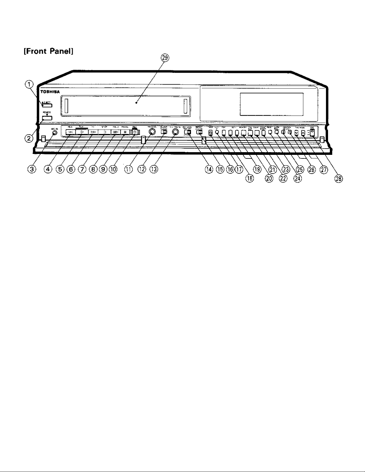
Location of Controls
EJECT button
©
When pressed, the cassette is automatically ejected from
the cassette compartment,
POWER button
©
Turns this VCR's power on and off- When off, the display
panel will show ''OFF''. The TO WOT button is disabled
while in the record lock mode or in the alarm record mode.
MIC IN jack
When using this microphone jack as an audio irtput, the
RCA Jack input will be switched off.
REW/REVERSE PICTURE SEARCH button
0
Pressing the RBW button with the tape stopped causes
the tape to be rewound. Pressing the flf W button during
playback causes the picture to be played back at 5 times
the normal speed in the reverse direction.
PLAY button
Pressing the PLAK button starts the playback mode.
FF/FORWARD PICTURE SEARCH bunon
Pressing the FF button with the tape stopped causes the
tape to be fast-forwarded. Pressing the FF button during
playback causes the picture to be played back at 6 times
the normal speed in the forward direction.
STOP button
©
Pressing the STOP button while in the playback or record
will cancel the mode.
FIELD button
®
While in the playback mode, single frames may be viewed
by field pressing the PAUSE/STiLL button and then
advancing field by pressing the FIELD button. Keep the
button pressed to play back at about 1/30 of the normal
speed.
PAUSE button
0
Pressing the Mi/Sf button while in the record mode stops
tape movement and recording. Pressing the ML/Sf button
while in the playback mode stops the tape and displays
a still picture. Pressing the PAUSE button twice cancels
this mode.
REC button
Pressing the REC button will begin recording in the mode
selected.
0 TRACKING control
Rotating this control while in the 2-hour playback mode
will eliminate tracking noise from the picture.
(T?) BUZZER switch
This switch is the on/off switch for the buzzer. The buzzer
will sound in different ways depending on that condition;
If there is moisture in the heads (DEW) the buzzer will
sound continuously. When the tape reaches its end in the
record mode, the buzzer will sound continuously. The
buzzer may be cancelled by pressing this button. The
buzzer will beep five times if recording is attempted with
the record protect tab removed or when the timer button
is pressed.
(l|l FIELD TRACKING control
Rotating this control while in any field advance mode will
eliminate tracking noise from the picture.
@ REC LOCK/RESTART switch
Setting the REC LOCK/RESTART switch to the "ON"
position will disable all controls while in the record mode,
thereby protecting against unauthorized or accidental
termination. In the event of a power failure this VCR will
automatically resume recording when power is restored.
Setting the REC LOCK/RESTART switch to the "OFF"
position cancels these functions.
See page 1 3.
(i|) REPEAT switch
The record mode may be set so that when the the tape
reaches the end it will be rewound and resume recording.
This is accomplished by setting the REPEAT switch to the
"ON'' position,
(l|) TIMER button
This button is used to begin timer recording after they have
been programmed.

Head cleaner and power faHs display
• A head cleaning unit is provided to prevent the head from being clogged- When the tape end has been detected during
recording, when the video cassette has been ejected and once every 2 hours during recording pause, the head cleaner will
automatically operate for about 1 second.
• When the tape end is detected, an electric buzzer sounds and the counter display blinks. To stop the blinking, press any button.
• When power fails, the 'TWTAIL" mark blinks on the display. Press any button to erase the mark.
(Í7) CLOCK SET button
This button is used to program the time. {Refer to detailed
programming instructions,)
(J|) PGM button
This button is used program the timer, (Refer to detailed
programming instructions.)
@ SET (-)/( + ! button
These buttons are used to program the time or timer. {Refer
to detailed programming instructions,)
MEMORY button
This button is used to program the time or timer. (Refer
to detailed programming instructions.)
@ CFM/SKIP button
Pressing the CFM (confirm) button while in the stop mode
causes the contents of the timer memory to be shown on
the on-screen display. Press this button In timer setting
mode. "SKIP" is displayed where programmed times were,
and the program will be skipped for recording. Press it again
to display the programmed times.
COUNT, button
Pressing the COUf^T. button displays the tape counter or
the alarm counter on the MODE DISPLAY,
COUNT. MEMORY button
Pressing the COU^T. MEMORY button causes the
"CiDUNT. M” (counter memory) to appear on the MODE
DISPLAY. If the tape is fast-forwarded or rewound while
in this mode the tape will stop automatically at a count
of "0000", Pressing this button twice causes the "ALARM
M" (alarm memory) to be displayed. If the tape is fastforwarded or rewound while in this mode the tape will stop
automatically at the beginning of an alarm and enter the
STILL, PLAYBACK mode. Pressing the buttor> three times
carreéis this function.
RESET button
• Pressing the RESET button while in the tape counter
mode resets the tape counter to "0000", Pressing the
RESET button while in the alarm counter mode resets
the alarm counter to "A-00".
• Press this button to release the alarm recall that has been
recorded, (max 5 programs)
ALARM RECALL button
Pressing the ALARM RECALL button while in the stop
mode will begin an on-screen review of all alarms which
have been recorded. Each alarm will be displayed along
with the time and date associated with that alarm of 5 se
conds. During this sequential display period the SET ( + )
and SET {- ) buttons may be used to advance or recall the
alarms displays.
LOCATION SELECT buttons
Pressing these buttons will position the on-screen display.
The display will move in the direction of the arrows marked
on the buttons. When the display reaches the border of
the picture it will "wrap around'' to the other side.
TIME MODE buttons
These buttons are used to select recording speed. Press
ing the button marked with the up or down arrow will
increase or decrease the record speed which will be shown
on the display panel.
ON SCREEN DISPLAY switch
This switch allows you to select how much information
appears in the on-screen display. In the "OFF" position
the entire display is off. In the "1ST" position only one
line containing time and alarm information will be dis
played. tn the "2ND" position a second line containing date
information will be displayed.
CASSETTE COMPARTMENT
When a cassette is inserted into the cassette compartment,
the mechanism will automatically load the tape into this
VCR.
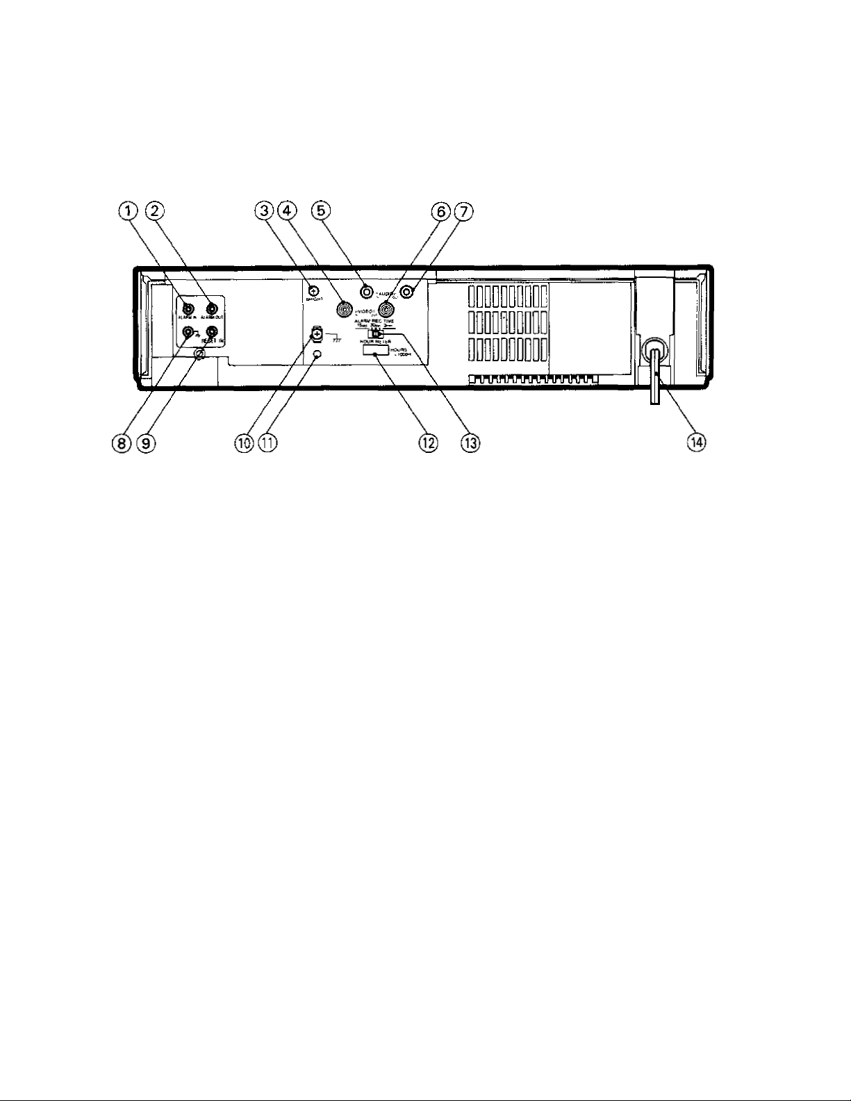
Location of Controls
[Rear Panel]
ALARM IN terminal
An alarm to ground at this terminal begins the alarm mode
recording sequence.
ALARM OUT terminal
This terminal outputs alarm signals.
BRIGHT control
The on-screen display brightness may be set by rotating
The BRIGHT controL
0 VIDEO IN jack
This BNC jack is a terminated video input.
0 AUDIO IN jack
This RCA jack is an audio line input.
0 VIDEO OUT jack
This BNC jack is a video output used to drive a monitor,
switcher, or other equipment.
0 AUDIO OUT jack
This RCA jack is an audio line output used to drive other
audio equipment.
GROUND terminal
This is the ground terminal for the alarm input.
0 RESET IN terminal
Ground at this terminal will cancel an existing alarm
recording sequence.
0 GROUND terminal
This terminal is used to connect other equipment.
0 ALL CLEAR button
• Pressing this button will clear the entire time/date, and
timer program memory. The power will be turned off at
the same time. Pressing the POWER button will restore
power.
• Press this button if the VCR malfunctions,
0 10000 HOUR mater
The 10000 HOUR meter displays the total number of hours
this VCR has been in service.
0 ALARM REC TIME switch
The ALARM REC TfME switch is used to set the alarm
recording time to 1 5 seconds, 30 seconds, or 3 minutes.
0 POWER CORD
 Loading...