

Page 1

General Precautions for Installation/Servicing/Maintenance for the KK-1600
The installation and service should be done by a qualified service technician.
1. When installing the KK-1600 to the Plain Paper Copier , be sure to follo w the instructions described in
the “Unpacking/Set-Up Procedure for the KK-1600” booklet which comes with each unit of the
KK-1600.
2. The KK-1600 should be installed by an authorized/qualified person.
3. Before starting installation, servicing or maintenance work, be sure to turn off and unplug the copier
first.
4. When servcing or maintaining the KK-1600, be careful about the rotating or operation sections such
as gear, pulleys, sprockets, cams, belts , etc.
5. When parts are disassembled, reassembly is basically the rev erse of disassembly unless otherwise
noted in this manual or other related materials. Be careful not to reassemble small parts such as
screws, washers, pins , E-rings, toothed washers to the wrong places .
6. Basically, the machine should not be operated with any parts removed or disassembled.
7. Delicate parts for preventing safety hazard problems (such as breakers, thermofuses, fuses, door
switches, sensors, etc. if any) should be handled/installed/adjusted correctly.
8. Use suitable measuring instruments and tools.
9. During servicing or maintenance wor k, be sure to check the serial No. plate and other cautionary
labels (if any) to see if they are clean and firmly fixed. If not, take appropriate actions.
10. The PC board must be stored in an anti-electrostatic bag and handled carefully using a wristband,
because the ICs on it may be damaged due to static electricity. Before using the wrist band, pull out
the power cord plug of the copier and make sure that there is no uninsulated charged objects in the
vicinity.
11. For the recov ery and disposal of used KK-1600, consumable parts and packing materials, it is recommended that the relev ant local regulations/rules should be follo wed.
12. After completing installation, servicing and maintenance of the KK-1600, return the KK-1600 to its
original state, and check operation.
Copyright 2000
TOSHIB A TEC CORPORATION
Page 2

CONTENTS
1. SPECIFICATIONS....................................................................................................... 1-1
2. OUTLINE..................................................................................................................... 2-1
2.1 Names of Various Components........................................................................................ 2-1
2.2 Layout of Electrical Parts ................................................................................................. 2-2
2.3 Harness Connection Diagram .......................................................................................... 2-4
2.4 Board Assembly ............................................................................................................... 2-5
3. OPERATIONAL DESCRIPTION ................................................................................. 3-1
3.1 General Description ......................................................................................................... 3-1
3.2 Block Diagram.................................................................................................................. 3-1
3.3 Detection of Abnormal Status ..........................................................................................3-2
3.4 Flow Chart........................................................................................................................ 3-3
4. MECHANICAL DESCRIPTION................................................................................... 4 - 1
4.1 Mechanism Drawing......................................................................................................... 4-1
4.2 Staple Operation .............................................................................................................. 4-1
5. CIRCUIT DESCRIPTION ............................................................................................ 5-1
5.1 PWA Block Diagram......................................................................................................... 5-1
5.2 Functional Description...................................................................................................... 5-1
5.3 Signal Description ............................................................................................................ 5-2
5.4 Timing Charts............................................................................................................... .... 5-3
6. DISASSEMBLY AND REPLACEMENT...................................................................... 6- 1
October 2000 © T OSHIBA TEC 1 KK-1600 CONTENTS
Page 3

1. SPECIFICATIONS
Type of stapling : Flat clinch method
2
No. of sheets stapled : 52g/m
52g/m
Paper thickness : Max. 5.5 mm
Staple capacity : 5000 staples
Dimensions : 257 (W) x 423 (D) x 173 (H) mm
Weight : Approx. 3.4 kg
Power supply : 100V - 240V (Supplied from copier)
paper, 2 sheets to 80g/m2 paper, 50 sheets
2
paper, 2 sheets to 80g/m2 paper, 48 sheets + 200g/m2, 2 sheets
October 2000 © T OSHIBA TEC 1 - 1 KK-1600 SPECIFICATIONS
Page 4

2. OUTLINE
2.1 Names of Various Components
STP power lamp
STP power code
STP base
STP staple cartridge
STP staple unit
STP 02-01-01
STP 02-01-02
October 2000 © T OSHIBA TEC 2 - 1 KK-1600 OUTLINE
Page 5

2.2 Layout of Electrical Parts
STP AC adapter
STP LED PWA
STP1
STP 02-02-01
STP2
M1 SW2
SW1
SEN2
SEN1
STP 02-02-02
KK-1600 OUTLINE 2 - 2 October 2000 © T OSHIBA TEC
Page 6

Symbols and functions of various devices
Symbol
SW1
SW2
SEN1
SEN2
M1
STP1
STP2
LED
Name
STPCOV-SW
STP cover open switch
EMPTY-SW
STP staple empty switch
PSET-SEN
STP paper set sensor
HP-SEN
STP home position sensor
STP motor
STP CONT PWA
STP sensor PWA
STP LED PWA
Function
Detects the open/close state of the cover during staple replacement, etc.
Detects the presence or absence of staples.
Detects the loading of the paper to be stapled.
Detects the home position of the drive section.
Drive the stapler.
PWA which controls the stapler.
PWA which relays the sensor signals and motor drive signals.
PWA on which the power lamp (LED) is installed.
October 2000 © T OSHIBA TEC 2 - 3 KK-1600 OUTLINE
Page 7

2.3 Harness Connection Diagram
AC
adapter
AC IN
24V
GND
J2
J1
1
2
J3
STP
CONT
PWA
1
2
1
2
3
4
5
6
7
24V
COVER
GND
H.P
5V
GND
Empty
CW
CCW
STP cover open switch
Staple unit
CN1
CN2
CN3
1
2
1
2
1
2
3
4
5
6
STP
sensor
PWA
7
M
STP motor
STP staple
empty switch
STP home
position sensor
J4
5V
1
GND
2
Set
3
STP paper set sensor
J5
GND
1
LED
2
STP LED PWA
STP 02-03-01
KK-1600 OUTLINE 2 - 4 October 2000 © T OSHIBA TEC
Page 8
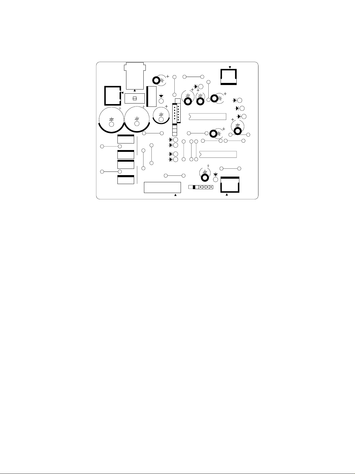
2.4 Board Assembly
2J2
C16
JP2
JP1
J1
2
3
1
FU1
Q7
S
DG
Q5
S
Q6
S
DG
Q4
DSG
STPL CONTROLLER
C11
JP15
1
R16R14
G
Q3
G
D6
1
IO
2
C9
C19
JP5
JP4
JP3
1
0
D8
D5
D7
D4
C6
JP7
MADE IN JAPAN
JP6
J3
JP16
D9
Q2
1
JP13
JP9
JP8
C1
W
C5
JP17
JP11 JP12
1
Q1
D1
2
C4
1
J5
C3
D2
D3
9
D10
4G1–1231
C8
JP14
8
02
JP10
J4
4H10109
3117
STP 02-04-01
October 2000 © T OSHIBA TEC 2 - 5 KK-1600 OUTLINE
Page 9

3. OPERATIONAL DESCRIPTION
3.1 General Description
Upon detecting the loading of paper, the STP operates the motor for staple operation. The AC input
supplied from the copier is converted to a DC voltage (24V) through the AC adapter in the STP and used
as a power supply for the STP.
3.2 Block Diagram
STP cover open switch
STP paper set sensor
STP LED PCB
Staple unit
M STP motor
STP staple empty switch
STP home position sensor
STP 03-02-01
AC
adapter
+24V
J2
J1
J4J5J3
STP
CONT
PWA
STP
sensor
PWA
The STP consists of the AC adapter, STP CONT PWA, sensors, power indicator LED, staple unit, etc.
The staple unit consists of the STP motor, STP Sensor PWA for relaying the sensor signals, mechanical
drive section, etc.
October 2000 © T OSHIBA TEC 3 - 1 KK-1600 OPERATIONAL DESCRIPTION
Page 10

3.3 Detection of Abnormal Status
• Cover Open/Close Detection
The STP cover open s witch turns OFF when the cover is opened. Since the s witch is connected to the
power supply, the power supply to the STP is cut when the switch turns OFF. For this reason, all the
operation is disabled while the cov er is open. When the STP cov er is closed, the delivery of the power
supply is resumed to light the STP power lamp and enable stapling.
• Staple Empty Detection
Upon detecting a staple empty state, the STP staple empty switch resets the motor drive circuit so that
the motor does not operate ev en if the STP paper set sensor detects the presence of paper . This error
state is reset when staples are supplied causing the STP paper set sensor to detect the presence of
staples.
KK-1600 OPERATIONAL DESCRIPTION 3 - 2 October 2000 © TOSHIBA TEC
Page 11

3.4 Flow Chart
Copier power ON
STP cover open
switch
Close
STP power lamp ON
Load paper into STP.
(STP paper set sensor ON)
STP staple
empty switch
OK?
OK
Open
STP power lamp OFF
NG
Stampling stopped
Supply staples
STP motor operates
to start stapling.
STP 03-04-01
October 2000 © T OSHIBA TEC 3 - 3 KK-1600 OPERATIONAL DESCRIPTION
Page 12
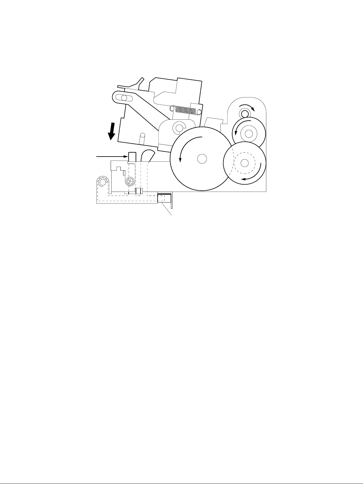
4. MECHANICAL DESCRIPTION
4.1 Mechanism Drawing
Paper set
STP paper set sensor
STP 04-01-01
4.2 Staple Operation
The staple operation of the STP is performed only by the rotation of the STP motor through the combination of the gears and cams.
The loading of paper is detected when the paper detection lev er is pushed. When paper is loaded into the
stapler, the paper detection lever is pushed causing the STP paper set sensor to detect the presence of
paper.
When the presence of paper is detected, if staples are availab le, the STP motor is operated to drive the
gears and cams to perform staple operation. If no staples are available, the STP does not operate until
staples are supplied. When one time of staple operation is finished, the STP returns to its original state
and stands by until the next presence of paper is detected.
Staples are loaded in the cartridge and its capacity is about 5,000 staples. When the cartridge is supplied with staples or a new cartridge is installed, perform staple operation without staples (7 to 8 times) to
feed staples to a position where stapling is possible.
October 2000 © T OSHIBA TEC 4 - 1 KK-1600 MECHANICAL DESCRIPTION
Page 13
5. CIRCUIT DESCRIPTION
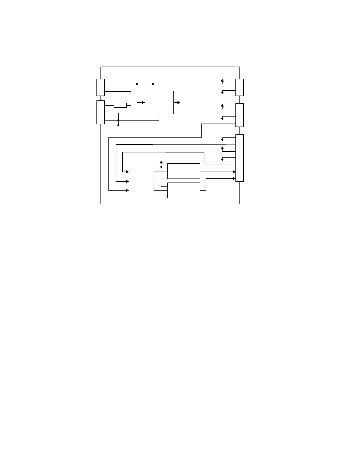
5.1 PWA Block Diagram
5V
STP cover open
switch
STP AC adapter
J2
J1
1
2
1
2
3
FU1
GND
Motor
24V
Q3
switching
regulator
PAPER_SENS
STPL_H/P
HOOK_SW
24V
Motor drive
5V
circuit
GND
GND
GND
5V
GND
CW
CCW
5V
1
2
STP LED PWA
J5J4J3
1
STP paper set
2
sensor
3
1
2
3
4
5
6
7
STP sensor PWA
controll
circuit
Motor drive
circuit
STP 05-01-01
5.2 Functional Description
The STP operates the stapler through the STP controller PWA. When the power of the copier is turned
on, a power supply is also delivered to the STP to enab le stapling. When paper is loaded into the stapler ,
the STP paper set sensor detects the presence of paper (changing from “High” to “Low”), and 200 ms
later the CW signal turns ON (changing from “Low” to “High”) to operate the STP motor forward. When
the motor operates, the gears and cams of the stapler operate for stapling. When the STP home position
sensor detects the home position of the stapler (changing from “High” to “Low”) after the CW signal is
activated, the CW signal turns OFF.
If the STP home position sensor remains at “High” le vel (a f ailure to return to the home position) for some
reason even if a fixed time (approx. 900 ms) has elapsed after the CW signal turns ON, the CW signal
turns OFF and 100 ms later the CCW signal is turned ON (changing from “Lo w” to “High”) to oper ate the
STP motor rev ersely. In practice, how e ver, if the STP has locked up mechanically , an o verload occurs so
that the fuse installed on the STP CONT PWA will blow or the protective circuit of the AC adapter will
function to cut the delivery of the power supply (shutdown).
If the stapler is not at the home position when the power is turned on (“High” le vel), about 60 ms later the
CCW signal is turned ON (changing from “Low” to “High”) to operate the motor reversely allowing the
stapler to return to the home position.
October 2000 © T OSHIBA TEC 5 - 1 KK-1600 CIRCUIT DESCRIPTION
Page 14

5.3 Signal Description
Signal Name
STPCOV
STPPSET
STPHP
STPEMP
Part Name
STP cover open
switch
STP paper set
sensor
STP home
position sensor
STP staple
empty switch
Functional Description
Detects the open/close
state of the cover during
staple replacement, etc.
Detects the loading of the
paper to be stapled.
Detects the home position
of the drive section.
Detects the presence or
absence of staples.
Status
Open: Power off
Low: Paper loaded
Low: Home position
Low: No staples
Note
Microswitch
Photo sensor
Photo sensor
Microswitch
The STP cover open switch detects the open or close state of the cover. A microswitch is used for the
switch. A power supply is delivered to the stapler when the cover is closed, and cut off when open.
The STP paper set sensor detects the loading of paper. A photo sensor is used f or the s witch. The signal
goes LOW when the paper to be stapled is loaded.
The STP home position sensor detects the home position of the stapler. A photo sensor is used for the
sensor. It is mounted on the STP sensor PWA and detects the home position every stapling.
The STP staple empty switch detects the presence or absence of staples. A microswitch is used for the
sensor. When staples have run out or no cartridge is mounted, the signal is detected at “Low” level.
KK-1600 CIRCUIT DESCRIPTION 5 - 2 October 2000 © T OSHIBA TEC
Page 15

5.4 Timing Charts
• Staple operation
200ms
STP paper set sensor
STP staple empty switch
STP home position sensor
CW
CCW
H
L
H
L
H
L
H
L
H
L
• Staple operation (When staples have run out during operation)
200ms 200ms
STP paper set sensor
STP staple empty switch
H
L
H
L
No staples
858ms
STP home position sensor
CW
CCW
H
L
H
L
H
L
October 2000 © T OSHIBA TEC 5 - 3 KK-1600 CIRCUIT DESCRIPTION
Page 16

• Reverse operation (When the motor has locked up)
200ms 900ms
STP paper set sensor
H
L
STP staple empty switch
STP home position sensor
CW
CCW
H
L
H
L
H
L
H
L
100ms
• Reverse operation (When the stapler is not at the home position at power on time)
POWER ON
STP paper set sensor
STP staple empty switch
H
L
H
L
H
L
STP home position sensor
CW
CCW
H
L
H
L
H
L
60ms
KK-1600 CIRCUIT DESCRIPTION 5 - 4 October 2000 © T OSHIBA TEC
Page 17
6. DISASSEMBLY AND REPLACEMENT
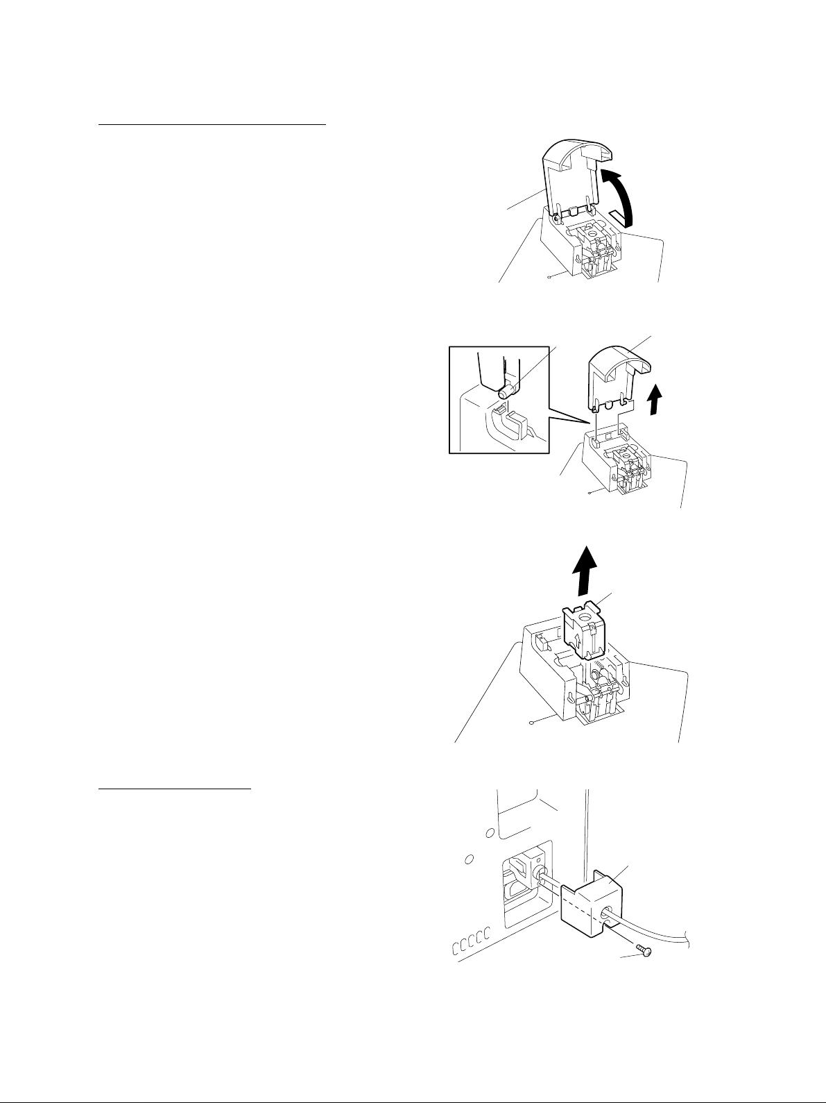
[A] STP cover/STP staple cartridge
1. Pull STP cover to release one hook and open
STP cover.
STP cover
314-1
Fig. 6-1
2. Release 2 hooks and detach STP cover.
3. Release 2 hooks and remove STP staple cartridge.
Hook
Fig. 6-2
STP cover
314-2
STP staple cartridge
321-1
Fig. 6-3
[B] STP bottom cover F
1. Remove one screw and detach connector cov er.
Connector cover
Screw
315
Fig. 6-4
October 2000 © TOSHIBA TEC 6 - 1 KK-1600 DISASSEMBLY AND REPLACEMENT
Page 18

2. Remove 2 scre ws and remove connector plate .
3. Release 2 hooks and detach connector .
Hook
4. Release the power cable from the hook of the
manual pocket.
5. Remove 2 screws , release 2 hooks, and remov e
stapler.
Connector plate
Manual pocket
Power cable
Hook
Screw
316-1
Fig. 6-5
316-2
Fig. 6-6
Stapler
317
Screw
Fig. 6-7
6. Remove one screw and detach STP bottom
cover F.
Screw
STP bottom cover F
318
Fig. 6-8
KK-1600 DISASSEMBLY AND REPLACEMENT 6 - 2 October 2000 © TOSHIBA TEC
Page 19

[C] STP bottom cover R
1. Remove stapler. (See Fig. 6-4 to 6-7)
2. Remove 4 screws and detach STP bottom cov er
R.
[D] STP staple cover
1. Detach STP cover. (See Fig. 6-1 and 6-2)
STP bottom cover R
Screw
Screw
319
Fig. 6-9
STP staple cover
2. Remove STP staple cartridge. (See Fig. 6-3)
3. Remove stapler. (See Fig. 6-4 to 6-7)
4. Detach STP bottom cover R. (See Fig. 6-9)
5. Remove one screw, release 5 hooks, and detach STP staple cover.
[E] STP cover open switch
1. Detach STP cover. (See Fig. 6-1 and 6-2)
2. Remove STP staple cartridge. (See Fig. 6-3)
3. Remove stapler. (See Fig. 6-4 to 6-7)
4. Detach STP bottom cover. (See Fig. 6-9)
5. Detach STP staple cover. (See Fig. 6-10)
6. Detach one connector from STP controller PWA
(J2) and release 3 clamps.
Hook
Clamp
Fig. 6-10
Fig. 6-11
Hook
Screw
Clamp
321-2
Connector
321-3
7. Remove one screw and remov e STP cover open
STP cover open switch
switch.
Screw
321-4
Fig. 6-12
October 2000 © TOSHIBA TEC 6 - 3 KK-1600 DISASSEMBLY AND REPLACEMENT
Page 20
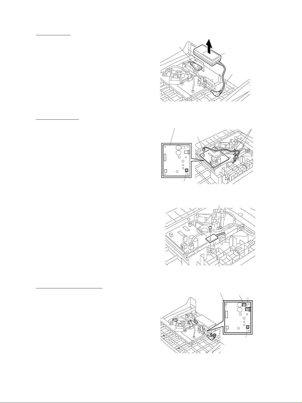
[F] AC adapter
1. Remove stapler. (See Fig. 6-4 to 6-7)
2. Detach STP bottom cover R. (See Fig. 6-9)
3. Detach AC adapter jack from STP controller
PWA (J1).
4. Detach power cord and remov e AC adapter.
[G] STP LED PW A
1. Remove stapler. (See Fig. 6-4 to 6-7)
2. Detach STP bottom cover R. (See Fig. 6-9)
3. Remove A C adapter. (See Fig. 6-13)
4. Detach one connector from STP controller PWA
(J5) and release 2 clamps.
5. Remove one screw and remo ve STP LED PW A.
Power cord
STP controller PWA
connector
J5
AC adapter
AC adapter jack
322-1
Fig. 6-13
clamp
322-2
Fig. 6-14
Screw
STP LED PWA
322-3
Fig. 6-15
[H] STP base stay assembly
1. Remove stapler. (See Fig. 6-4 to 6-7)
STP controller PWA
J2
J1
2. Detach STP bottom cover R. (See Fig. 6-9)
3. Detach AC adapter jack and the connectors
from STP controller PWA (J1/J2/J5).
4. Release 4 clamps.
J5
AC adapter jack
323
Fig. 6-16
KK-1600 DISASSEMBLY AND REPLACEMENT 6 - 4 October 2000 © TOSHIBA TEC
Page 21
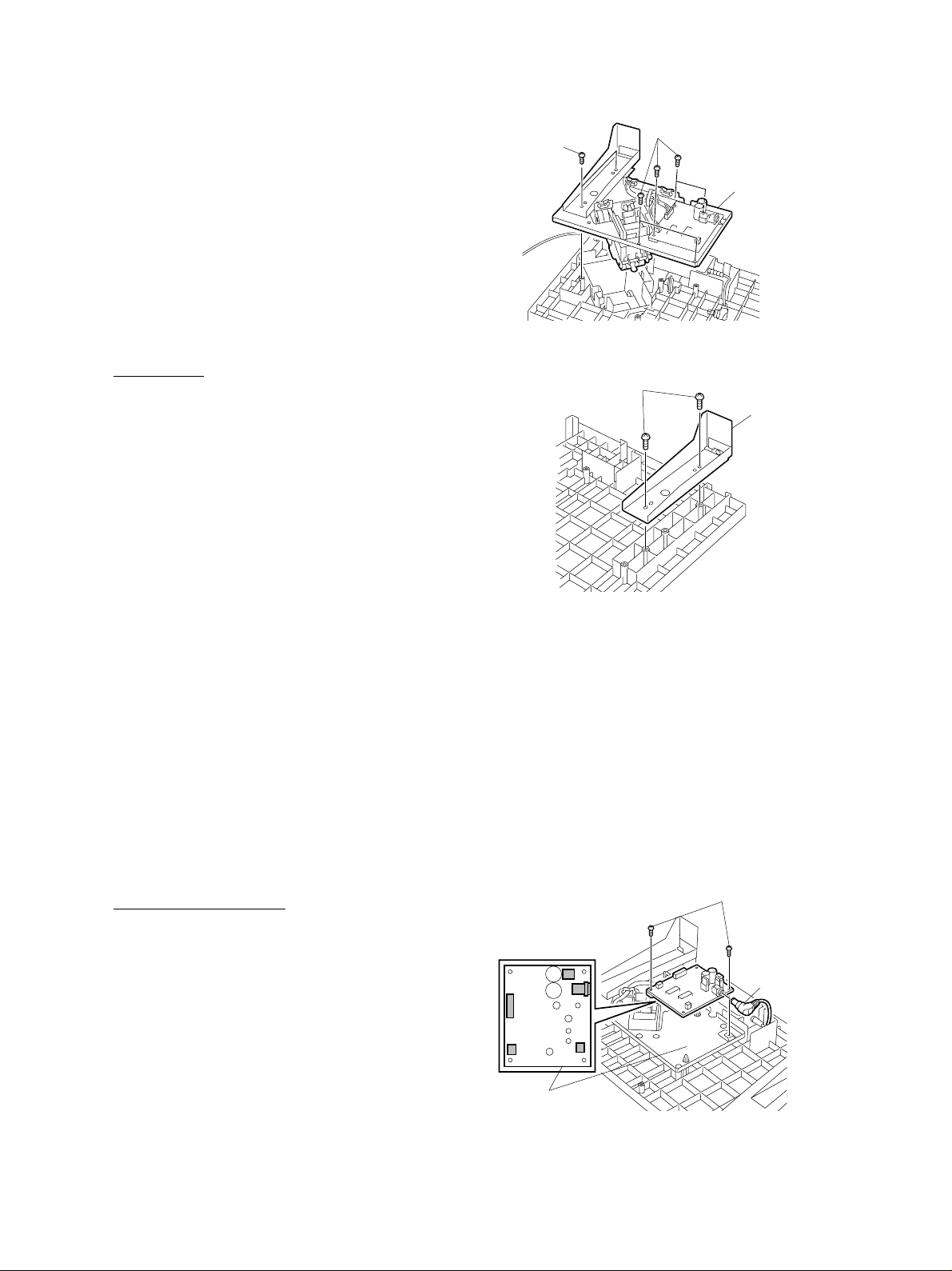
5. Remove 7 screws and remove STP base stay
assembly.
[I] STP base
1. Detach STP cover. (See Fig. 6-1 and 6-2)
2. Remove STP staple cartridge. (See Fig. 6-3)
3. Remove stapler. (See Fig. 6-4 to 6-7)
4. Detach STP bottom cover F. (See Fig. 6-8)
5. Detach STP bottom cover R. (See Fig. 6-9)
6. Detach STP staple cover. (See Fig. 6-10)
7. Remove STP cov er open switch. (See Fig. 6-11
Screw
Screw
STP base
stay assembly
324
Fig. 6-17
Screw
STP stay
and 6-12)
8. Remove A C adapter. (See Fig. 6-13)
9. Remove STP LED PWA. (See Fig. 6-14 and
6-15)
8. Remove STP base sta y assemb ly. (See Fig. 616 and 6-17)
9. Remove 2 scre ws and remo ve STP stay.
[J] STP controller PWA
1. Remove stapler. (See FIG. 6-4 to 6-7)
2. Detach STP bottom cover R. (See FIG. 6-9)
3. Detach AC adapter jack and all connectors from
STP controller PWA.
4. Remove 2 screws and remove STP controller
PWA.
STP
controller PWA
325
Fig. 6-18
Screw
AC adapter
jack
326
Fig. 6-19
October 2000 © TOSHIBA TEC 6 - 5 KK-1600 DISASSEMBLY AND REPLACEMENT
Page 22

[K] STP staple unit
1. Remove stapler. (See Fig. 6-4 to 6-7)
2. Detach STP bottom cover R. (See Fig. 6-9)
3. Remove STP base sta y assembly. (See Fig. 6-
STP controller PWA
Clamp
16 and 6-17)
4. Detach the connectors from STP controller PWA
(J3/J4) and release 2 clamps.
5. Remove 2 scre ws and remove STP staple unit.
J3
J4
327
Fig. 6-20
STP staple unit
Screw
328
Fig. 6-21
KK-1600 DISASSEMBLY AND REPLACEMENT 6 - 6 October 2000 © TOSHIBA TEC
 Loading...