

Page 1
SERVICE MANUAL
Paper Feed Pedestal
KD-1025
Model: KD-1025
Publish Date: April 2009
File No. SME090003B0
R090121H2600-TTEC
Ver02_2011-12
Page 2

Trademarks
• FLOIL is a registrated trademark of Kanto Kasei Ltd. CORPORATION
• Mylar is a registered trademark of DuPont Teijin Films U.S. Limited Partnership.
• Molykote is a registered trademark of Dow Corning Corporation.
• Other company names and product names in this manual are the trademarks of their respective
companies.
© 2009 - 2011 TOSHIBA TEC CORPORATION All rights reserved
Under the copyright laws, this manual cannot be reproduced in any form without prior written permission
of TOSHIBA TEC CORPORATION.
Page 3
GENERAL PRECAUTIONS FOR INSTALLATION/SERVICING/
MAINTENANCE
The installation and service shall be done by a qualified service technician.
1. When installing the Paper Feed Pedestal KD-1025 to the equipment, be sure to follow the
instructions described in the "Unpacking/Set-Up Procedure for the KD-1025" booklet which comes
with each unit of the KD-1025.
2. The KD-1025 should be installed by an authorized/qualified person.
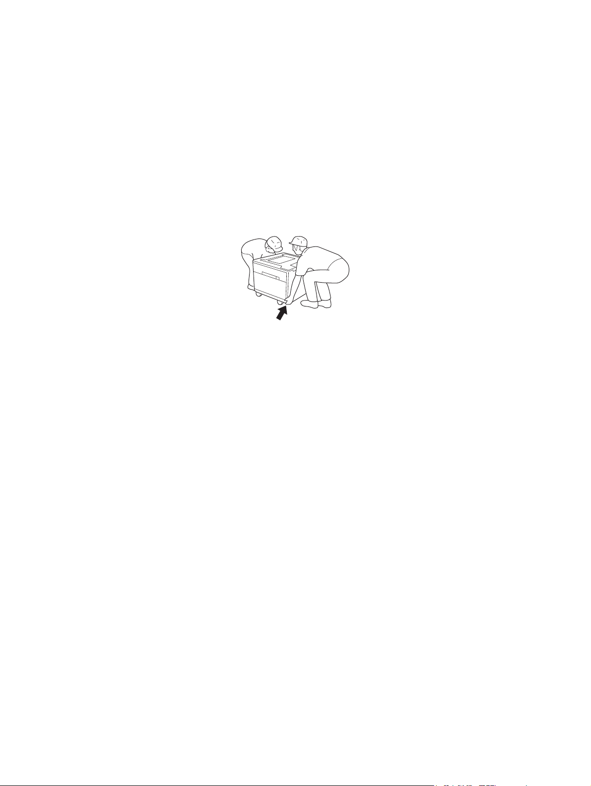
3. When transporting/installing KD-1025, employ two persons and be sure to use the positions as
indicated below.
KD-1025 is fairly heavy and weights approximately 21 kg (46.3 lb.), therefore pay full attention when
handling it.
4. Before starting installation, servicing or maintenance work, be sure to turn OFF and unplug the
equipment first.
5. Be sure to fix and plug in the power cable securely after the installation so that no one trips over it.
6. The equipment shall be installed near the socket outlet and shall be accessible.
7. Unplug the power cable and clean the area around the prongs of the plug and socket outlet once a
year or more. A fire may occur when dust lies on this area.
8. The KD-1025 is supplied with power from the equipment, requiring no additional power source.
9. The KD-1025 should be grounded to the specified positions on the machine frame.
10.When servicing or maintaining the KD-1025, be careful about the rotating or operating sections such
as gears, pulleys, sprockets, cams, belts, etc.
11.When servicing the machines with the power turned ON, be sure not to touch live sections and
rotating/operating sections.
12.When parts are disassembled, reassembly is basically the reverse of disassembly unless otherwise
noted in this manual or other related materials. Be careful not to reassemble small parts such as
screws, washers, pins, E-rings, toothed washers to the wrong places.
13.Basically, the machine should not be operated with any parts removed or disassembled.
14.Delicate parts for preventing safety hazard problems (such as thermofuses, door switches sensors,
etc. if any) should be handled/installed/adjusted correctly.
15.Use suitable measuring instruments and tools.
Page 4

16.During servicing or maintenance work, be sure to check the nameplate and other cautionary labels
(if any) to see if they are clean and firmly stuck. If not, take appropriate actions.
17.The PC board must be stored in an anti-electrostatic bag and handled carefully using a wristband,
because the ICs on it may be damaged due to static electricity.
Caution: Before using the wrist band, pull out the power cord plug of the equipment and
make sure that there is no uninsulated objects in the vicinity.
18.For the recovery and disposal of used the Paper Feed Pedestal, consumable parts, packing
materials, follow the relevant local regulations/rules.
19.Return the equipment to the original state and check the operation when the service is finished.
Page 5

CONTENTS
KD-1025
1. SPECIFICATIONS......................................................................................................... 1-1
2. OVERVIEW ................................................................................................................... 2-1
2.1 Front Sectional View............................................................................................................ 2-1
2.2 Layout of Electrical Parts ..................................................................................................... 2-2
2.3 Electrical Parts..................................................................................................................... 2-3
3. GENERAL OPERATION............................................................................................... 3-1
3.1 Driving System and Feeding Operation............................................................................... 3-1
3.2 Description of Operations ....................................................................................................3-2
3.3 Error Detection..................................................................................................................... 3-3
3.4 Flow Chart ........................................................................................................................... 3-4
4. DISASSEMBLY AND REPLACEMENT........................................................................ 4-1
4.1 Installation and Removal of Drawers and Covers................................................................ 4-1
4.2 PFP board (PWB) ................................................................................................................ 4-5
4.3 Upper/Lower Transport Rollers............................................................................................ 4-6
4.4 Motor ................................................................................................................................. 4-10
4.5 Feed/Separation/Pickup Roller .......................................................................................... 4-15
4.6 Switches and Sensors ....................................................................................................... 4-18
5. ELECTRIC CIRCUIT .....................................................................................................5-1
5.1 Harness Diagram................................................................................................................. 5-1
5.2 Circuit Diagram .................................................................................................................... 5-2
5.3 PC Board ............................................................................................................................. 5-5
6. PERIODIC MAINTENANCE.......................................................................................... 6-1
© 2009 - 2011 TOSHIBA TEC CORPORATION All rights reserved KD-1025
1
CONTENTS
Page 6

KD-1025 © 2009 - 2011 TOSHIBA TEC CORPORATION All rights reserved
CONTENTS
2
Page 7
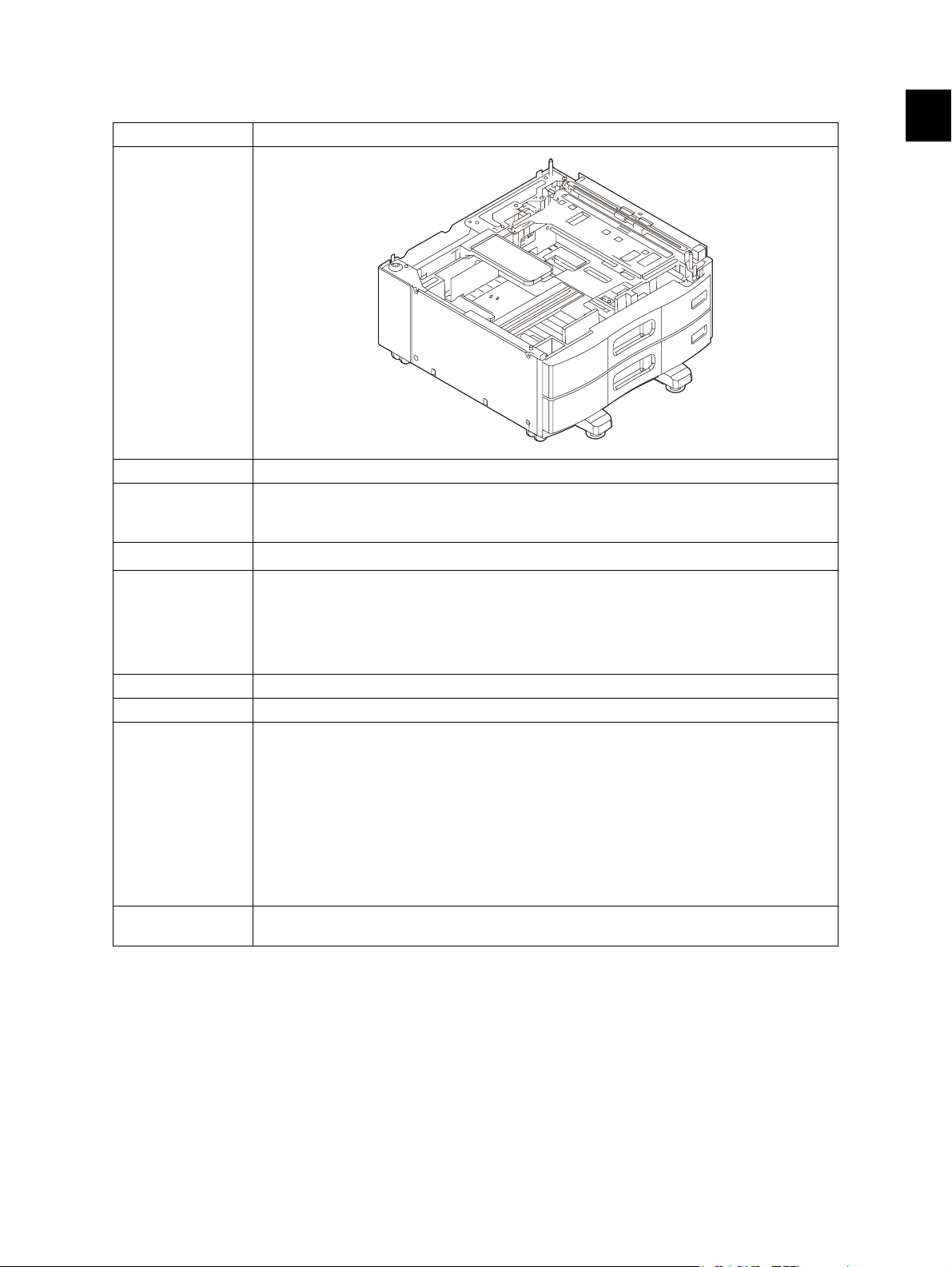
1. SPECIFICATIONS
Item KD-1025
Appearance
Feeding method Automatic feeding: 1 drawer installed from the front
Paper Size: A3, B4, A4, A4-R, B5, B5-R, A5-R, LD, LG, LT, LT-R, 8K, 16K, 16K-R, FOLIO,
Capacity of drawer
Dimensions 575 (W) × 583 (D) × 292 (H) mm
Weight Approx. 21 kg (46.3 lb.)
Power supply 5 V, 24 V (supplied from the equipment)
Accessory Unpacking Instructions (1)
Option Drawer module: MY-1033
COMPUTER, 13"LG, 8.5"x8.5"
Thickness: 64 g/m
Stack height: 60.5 mm (Approx. 550 sheets: 80 g/m
22.64 (W) × 22.95 (D) × 11.50 (H) inch
(Height - Floor to top of the front cover)
660 (W) × 701 (D) × 292 (H) mm
25.98 (W) × 27.60 (D) × 11.50 (H) inch
(Including the stabilizer cover)
Connecting plates (4)
Screws for connecting plates (6)
Fixing screw for ground wire (1)
Paper size indicator sheets (2)
Stabilizer brackets (4)
Feeding side stabilizer foot (1)
Screw for feeding side stabilizer foot (1)
Rear side stabilizer covers (2)
Front side stabilizer cover (1)
Screws for stabilizer (4)
(With this option, 2 drawers become available for feeding).
2
to 105 g/m2 (17 lb. Bond to 94.5 lb. Cover)
2
(22 lb. Bond))
1
Note:
This manual explains on the premise that 2 drawers are available (that is, the optional drawer
module is installed).
© 2009 - 2011 TOSHIBA TEC CORPORATION All rights reserved KD-1025
1 - 1
SPECIFICATIONS
Page 8

KD-1025 © 2009 - 2011 TOSHIBA TEC CORPORATION All rights reserved
SPECIFICATIONS
1 - 2
Page 9

2. OVERVIEW
2.1 Front Sectional View
16 17
8
9
24
28
Fig. 2-1
12
27
26
15
19
12
6
2523
Symbol Name Symbol Name
1 Upper drawer tray-up sensor (S4) 15 Upper drawer pickup roller
2 Upper drawer empty sensor (S6) 16 Upper drawer tray
10
13
14
11
20
21
22
18
4
5
3
7
2
3 Upper drawer feed sensor (S2) 17 Upper drawer elevator
4 Upper transport roller 18 Lower drawer tray-up sensor (S5)
5 Upper drawer feed clutch (CLT2) 19 Lower drawer empty sensor (S7)
6 Upper drawer feed roller 20 Lower drawer feed clutch (CLT3)
7 Upper drawer separation roller 21 Lower drawer feed roller
8 Upper drawer 22 Lower drawer separation roller
9 Lower drawer 23 Lower drawer pickup roller
10 Upper drawer tray-up motor (M2) 24 Lower drawer tray
11 Lower drawer feed sensor (S3) 25 Lower drawer tray-up motor (M3)
12 Upper drawer elevator coupling 26 Lower drawer elevator
13 Lower transport roller 27 Lower drawer elevator coupling
14 Transport clutch (CLT1) 28 Adjuster
© 2009 - 2011 TOSHIBA TEC CORPORATION All rights reserved KD-1025
2 - 1
OVERVIEW
Page 10
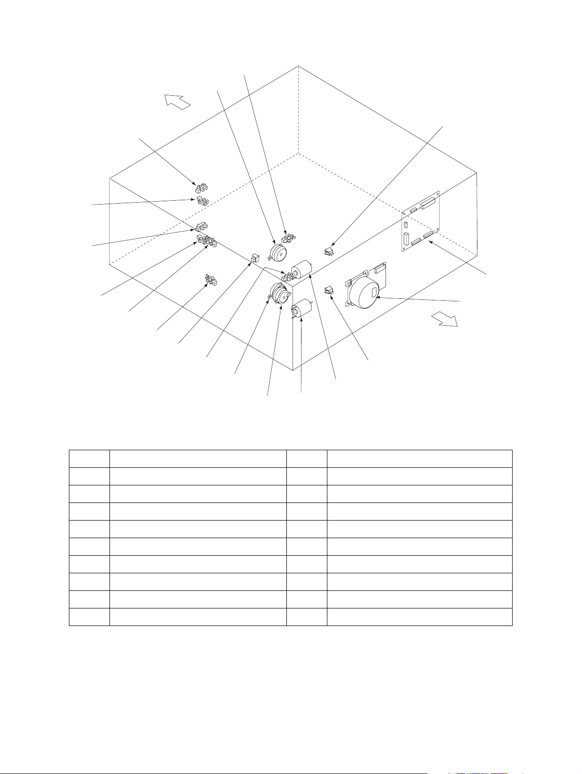
2.2 Layout of Electrical Parts
S10
Front side
CLT2
S4
S7
S5
S2
S6
S3
S1
S11
CLT3
CLT1
S8
PWB
M1
Rear side
S9
M2
M3
Fig. 2-2
Symbol Name Symbol Name
M1 PFP motor S4 Upper drawer tray-up sensor
M2 Upper drawer tray-up motor S5 Lower drawer tray-up sensor
M3 Lower drawer tray-up motor S6 Upper drawer empty sensor
CLT1 Transport clutch S7 Lower drawer empty sensor
CLT2 Upper drawer feed clutch S8 Upper drawer detection switch
CLT3 Lower drawer feed clutch S9 Lower drawer detection switch
S1 Side cover open/close switch S10 Upper drawer paper stock sensor
S2 Upper drawer feed sensor S11 Lower drawer paper stock sensor
S3 Lower drawer feed sensor PWB PFP board
KD-1025 © 2009 - 2011 TOSHIBA TEC CORPORATION All rights reserved
OVERVIEW
2 - 2
Page 11

2.3 Electrical Parts
1. Motor
Symbol Name Function Remarks
M1 PFP-MTR
PFP motor
M2 T-UP-U-MTR
Upper drawer tray-up motor
M3 T-UP-L-MTR
Lower drawer tray-up motor
Drives feeding and transport Brushless motor
Lifts up the upper drawer tray Brush motor
Lifts up the lower drawer tray Brush motor
2. Electromagnetic clutch
Symbol Name Function Remarks
CLT1 TR-CLT
Transport clutch
CLT2 FED-U-CLT
Upper drawer feed clutch
CLT3 FED-L-CLT
Lower drawer feed clutch
Drives transport
Drives roller to pick up paper from
the upper drawer
Drives roller to pick up paper from
the lower drawer
3. Switches and Sensors
Symbol Name Function Remarks
S1 SIDE-COV-SW
Side cover open/close switch
S2 FED-U-SNR
Upper drawer feed sensor
Side cover open/close detection Push switch
Detects timing to feed paper/
misfeeding
Photo interrupter
2
S3 FED-L-SNR
Lower drawer feed sensor
S4 TOP-U-SNR
Upper drawer tray-up sensor
S5 TOP-L-SNR
Lower drawer tray-up sensor
S6 EMP-U-SNR
Upper drawer empty sensor
S7 EMP-L-SNR
Lower drawer empty sensor
S8 CST-U-SW
Upper drawer detection switch
S9 CST-L-CST
Lower drawer detection switch
S10 PST-U-SNR
Upper drawer paper stock sensor
S11 PST-L-SNR
Lower drawer paper stock sensor
Detects timing to feed paper/
misfeeding
Detects if the upper drawer has
lifted up
Detects if the lower drawer has
lifted up
Detects presence/absence of paper
in the upper drawer
Detects presence/absence of paper
in the lower drawer
Detects the presence/absence of
the lower drawer
Detects the presence/absence of
the lower drawer
Detects that the paper stock is
insufficient in the upper drawer
Detects that the paper stock is
insufficient in the lower drawer
Photo interrupter
Photo interrupter
Photo interrupter
Photo interrupter
Photo interrupter
Push switch
Push switch
Photo interrupter
Photo interrupter
4. PC board
Symbol Name Function Remarks
PWB PWB-F-503S
PFP board
© 2009 - 2011 TOSHIBA TEC CORPORATION All rights reserved KD-1025
Control of PFP devices
OVERVIEW
2 - 3
Page 12

KD-1025 © 2009 - 2011 TOSHIBA TEC CORPORATION All rights reserved
OVERVIEW
2 - 4
Page 13
3. GENERAL OPERATION
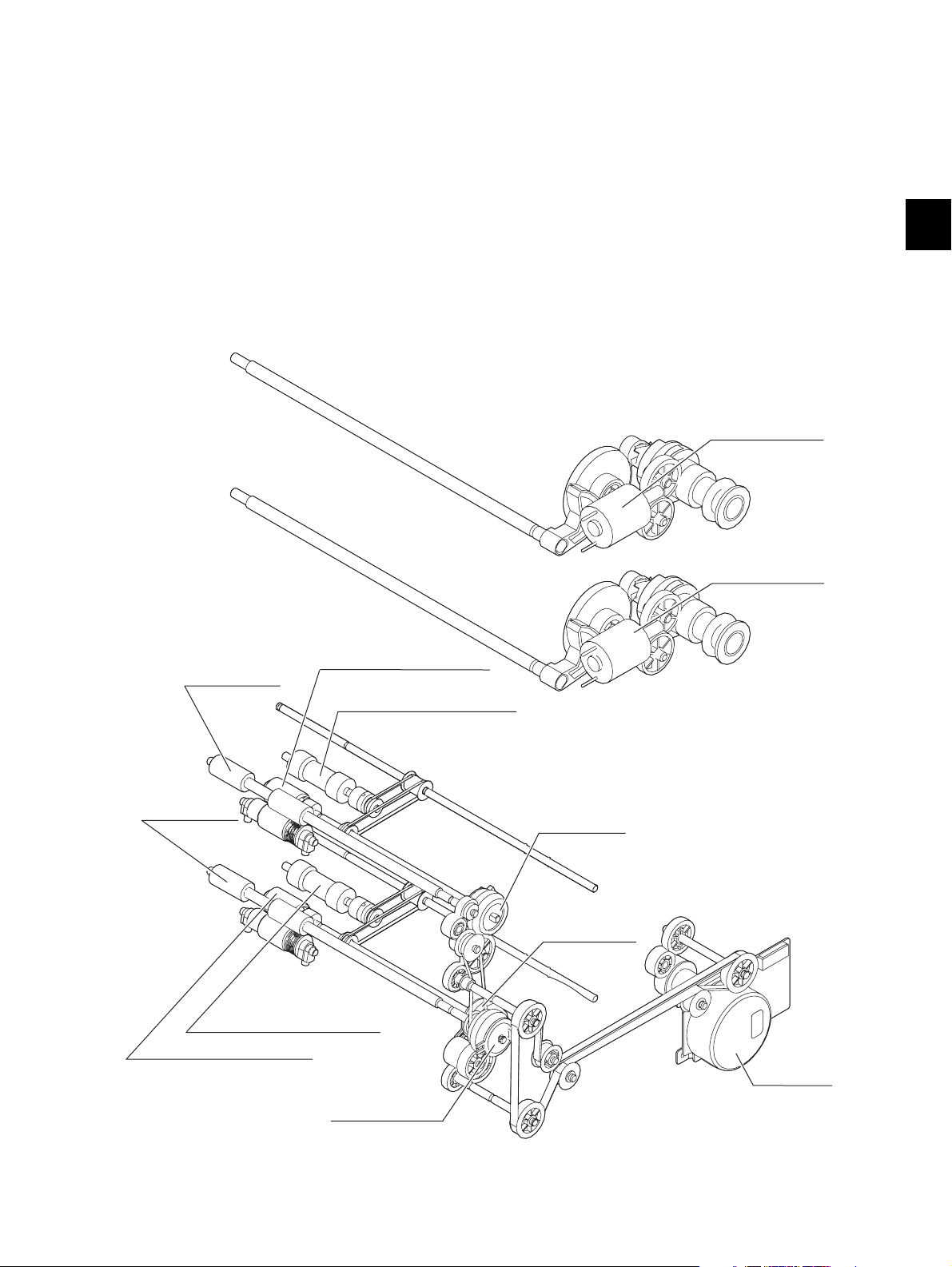
3.1 Driving System and Feeding Operation
The Paper Feed Pedestal (PFP) mainly consists of the drawer, pickup roller, feed roller, separation
roller, transport roller, and drive systems for these components.
• Feeding/Transport system
The PFP motor drives the pickup roller, feed roller, and transport roller which are located in the
feeding area.
• Drawer tray system
This system raises and lowers the tray.
Upper drawer
tray-up motor
3
Upper
transport roller
Lower
transport roller
Lower drawer
tray-up motor
Upper drawer feed roller
Upper drawer pickup roller
Upper drawer
feed clutch
Lower drawer
feed clutch
Lower drawer pickup roller
Lower drawer feed roller
PFP motor
Transport clutch
Fig. 3-1
© 2009 - 2011 TOSHIBA TEC CORPORATION All rights reserved KD-1025
3 - 1
GENERAL OPERATION
Page 14

3.2 Description of Operations
[A] From power ON to ready
(1) When the equipment is turned ON, the power is also supplied to the feeder unit. And when the
power is supplied, the feeder unit detects and judges the clock frequency output from the LGC
board on the equipment to control transport speed of the unit.
(2) After that, the tray-up motor (M2)/(M3) is turned ON to raise the corresponding tray. When the
tray-up sensor (S4)/(S5) is turned ON correspondingly, the tray-up motor (M2)/(M3) is turned
OFF to stop the tray. If the empty sensor (S6)/(S7) is OFF (H) at this time, it is judged that there
is no paper in the drawer. If the empty sensor is ON (L), it is assumed that there is paper in the
drawer, and the tray stays in the raised position until the drawer is pulled out.
(3) If the power is turned ON when the drawer has been pulled out, the tray-up motor for that drawer
is not turned ON. The tray is raised as soon as the drawer is installed, and it detects if there is
paper in the drawer.
(4) If either of the drawer feed sensors (S2), (S3) is ON (there is paper in the transport path) when
the power is turned ON, that means paper jam has occurred and operation is disabled until the
paper is removed.
[B] Ready status
(1) Trays detect the paper as described above, and the equipment goes into ready status.
(2) The tray goes down automatically when the drawer is removed and it is raised as soon as the
drawer is installed again and checks if there is paper in the drawer.
[C] From the start to the end of copying
(1) When the [START] button is pressed, the feed/transport and exit motors of the equipment and
the PFP motor (M1) are turned ON at the same time.
(2) When the equipment judges that PFP is ready for feeding paper, it turns ON the feed clutch
(CLT2)/(CLT3) of the selected drawer. This clutches drive the pickup roller and feed roller to feed
paper from the tray.
(3) When the drawer feed sensor (S2)/(S3) comes ON, the transport clutch (CLT1) is turned ON to
drive the PFP transport roller.
(4) A fixed time after the drawer feed sensor (S2)/(S3) comes ON, the feed clutch (CLT2)/(CLT3) is
turned OFF and feeding from the drawer is completed.
(5) The paper is transported to the equipment by the PFP transport roller. A fixed time after the
leading edge of the paper reaches the drawer feed sensor (S2), if the trailing edge of the
previously sent sheet still remains at the copier feed sensor, the transport clutch (CLT1) is turned
OFF to stop the transport of the paper.
(6) A fixed time after the paper turns the resist clutch ON, PFP becomes ready for feeding the next
sheet of paper, and the procedures (1) to (5) are repeated.
(7) When the copying operation is completed, the feed/transport motor, exit motor, PFP motor (M1),
and transport clutch(CLT1) are turned OFF and the transport roller is stopped.
KD-1025 © 2009 - 2011 TOSHIBA TEC CORPORATION All rights reserved
GENERAL OPERATION
3 - 2
Page 15

3.3 Error Detection
[A] Jam detection
(1) Paper jams (E150), (E160) and (E300 to E360) occur in the following cases.
• Feed sensor (S2)/(S3) is not turned ON within a specified period of time after the feeding is
started.
• The leading edge of the paper does not pass the feed sensor (S2)/(S3) in the transport path
within a specified period of time.
(2) Open the side cover of the PFP and remove all the paper remaining on the transport path and
close the side cover to clear the paper jam. If either of the drawer feed sensors (S2)/(S3) is still
ON when the side cover is closed, it is determined that there is still paper on the transport path
and the paper jam status is not cleared.
(3) When a paper jam occurs in the PFP during continuous copying, the paper that was fed before
the jam is copied normally.
[B] Call for Service
(1) The tray is raised when the power is turned ON or the drawer is inserted or pulled out. If the tray-
up sensor (S4)/(S5) is not turned ON within a specified period of time after the tray has started to
raise, a message that the selected drawer cannot be used is displayed on the control panel.
3
(2) The state (1) is cleared by opening the drawer and solving the problems.
© 2009 - 2011 TOSHIBA TEC CORPORATION All rights reserved KD-1025
3 - 3
GENERAL OPERATION
Page 16

3.4 Flow Chart
(Upper drawer feeding)
Press [START
Transport system control
Feed/transport motor ON
Exit motor ON
PFP motor ON
PFP motor
rotating normally?
Upper drawer feed clutch ON
PFP
Upper drawer feed
sensor ON?
PFP transport clutch ON
]
YES
YES
NO
Call for Service
"C040"
NO
Paper jam
"E150"
Upper drawer feed clutch OFF
2nd drawer feed sensor
Copier’s transport clutch ON
B
KD-1025 © 2009 - 2011 TOSHIBA TEC CORPORATION All rights reserved
GENERAL OPERATION
Copier’s
ON?
YES
A
Fig. 3-2
3 - 4
NO
Paper jam
"E320"
Page 17

AB
Copier’s
1st drawer feed sensor
ON?
YES
Copier’s registration
sensor ON?
YES
Copier’s registration
clutch
Counter ON/OFF
Copier’s transport clutch OFF
PFP transport clutch OFF
Copier’s registration
clutch
Copier’s
exit sensor
ON?
ON
OFF
NO
NO
NO
3
Paper jam
"E310"
Paper jam
"E300"
Paper jam
"E010"
Copier’s
exit sensor
OFF?
NO
Remaining number of
copies = 0?
Feed/transport motor OFF
Exit motor OFF
PFP motor OFF
Ready
Fig. 3-3
YES
YES
YES
NO
Paper jam
"E020"
© 2009 - 2011 TOSHIBA TEC CORPORATION All rights reserved KD-1025
3 - 5
GENERAL OPERATION
Page 18

KD-1025 © 2009 - 2011 TOSHIBA TEC CORPORATION All rights reserved
GENERAL OPERATION
3 - 6
Page 19

4. DISASSEMBLY AND REPLACEMENT
4.1 Installation and Removal of Drawers and Covers
[A] Drawers
(1) Pull out the drawer fully and remove 1 screw
at the back right to remove the stopper.
(2) Pull out the drawer further and take it out.
Fig. 4-1
[B] Drawer cover
4
Stopper
(1) Take out the drawer.
P.4-1 "[A] Drawers"
(2) Remove 4 screws and take off the drawer
cover.
Fig. 4-2
© 2009 - 2011 TOSHIBA TEC CORPORATION All rights reserved KD-1025
4 - 1
DISASSEMBLY AND REPLACEMENT
Page 20

[C] Stabilizer cover
(1) Take out the drawer.
P.4-1 "[A] Drawers"
Note:
The drawer must be taken out only when
taking off the front side stabilizer cover.
(2) Remove 2 screws and take off the front side
stabilizer cover.
(3) Remove 1 screw and take off the feeding
side stabilizer foot.
(4) Remove 2 screws and take off the rear side
stabilizer cover.
Feeding side
stabilizer foot
Front side
stabilizer cover
Fig. 4-3
[D] Rear cover
(1) Take off the rear side stabilizer cover.
P.4-2 "[C] Stabilizer cover"
(2) Remove 2 screws on the rear cover.
(3) Take off the rear cover.
Rear side stabilizer cover
Fig. 4-4
Fig. 4-5
KD-1025 © 2009 - 2011 TOSHIBA TEC CORPORATION All rights reserved
DISASSEMBLY AND REPLACEMENT
4 - 2
Page 21

[E] Feeding side front cover
(1) Take out the drawer.
P.4-1 "[A] Drawers"
(2) Remove 2 screws and take off the feeding
side front cover.
[F] Feeding side rear cover
(1) Open the side cover.
(2) Remove 2 screws, and take off the feeding
side stabilizer foot and the feeding side rear
cover.
4
Fig. 4-6
[G] Side cover
(1) Open the side cover and remove 1 screw on
the belt.
Feeding side rear cover
Feeding side stabilizer foot
Fig. 4-7
Belt
Fig. 4-8
© 2009 - 2011 TOSHIBA TEC CORPORATION All rights reserved KD-1025
4 - 3
DISASSEMBLY AND REPLACEMENT
Page 22

(2) Take off the block from the side cover.
(3) Take off the side cover while pushing the
front side of the side cover inward.
(4) Disconnect 1 connector.
Block
Fig. 4-9
Connector
Fig. 4-10
KD-1025 © 2009 - 2011 TOSHIBA TEC CORPORATION All rights reserved
DISASSEMBLY AND REPLACEMENT
4 - 4
Page 23

4.2 PFP board (PWB)
(1) Take off the rear cover.
P.4-2 "[D] Rear cover"
(2) Disconnect 6 connectors, remove 2 screws,
and release 2 locking supports to take off the
PFP board.
Locking
supports
Fig. 4-11
Screws
4
PFP board
© 2009 - 2011 TOSHIBA TEC CORPORATION All rights reserved KD-1025
4 - 5
DISASSEMBLY AND REPLACEMENT
Page 24

4.3 Upper/Lower Transport Rollers
[A] Upper transport roller
(1) Open the side cover and remove 1 screw on
the belt.
P.4-3 "[G] Side cover"
(2) Remove 3 screws and take off the transport
roller along with the bracket.
(3) Remove 1 clip, and take off the gear and the
collar.
Bracket
Fig. 4-12
Collar
(4) Remove 1 clip and slide the bushing to take
off the transport roller.
Gear
Clip
Bushing
Clip
Fig. 4-13
Transport rollers
Fig. 4-14
Bushing
KD-1025 © 2009 - 2011 TOSHIBA TEC CORPORATION All rights reserved
DISASSEMBLY AND REPLACEMENT
4 - 6
Page 25

[B] Lower transport roller
(1) Take off the rear cover.
P.4-2 "[D] Rear cover"
(2) Loosen 1 screw fixing the tensioner bracket.
(3) Remove the belt.
4
Fig. 4-15
Note:
When installing the belt, be sure to confirm
the gap between the belts with the following
procedure.
1. Install the belt in KD-1025.
2. Tighten 1 fixing screw of the tensioner
bracket.
3. Confirm that the gap between the belts is
approx. 3 mm.
Fig. 4-16
Approx.3mm
Fixing screw
Fig. 4-17
© 2009 - 2011 TOSHIBA TEC CORPORATION All rights reserved KD-1025
4 - 7
DISASSEMBLY AND REPLACEMENT
Page 26

(4) Remove 2 screws and take off the bracket of
the feeding gear.
(5) Remove 1 connector and take off the
transport clutch.
Fig. 4-18
Transport clutch
(6) Remove the coupling, pin, and clip.
Connector
Fig. 4-19
Coupling
Pin
Clip
Fig. 4-20
KD-1025 © 2009 - 2011 TOSHIBA TEC CORPORATION All rights reserved
DISASSEMBLY AND REPLACEMENT
4 - 8
Page 27

(7) Take off the side cover and the feeding side
front cover.
P.4-3 "[G] Side cover"
P.4-3 "[E] Feeding side front cover"
(8) Remove 3 screws and take off the transport
roller along with the bracket.
(9) Remove 1 clip, and take off the gear and the
collar.
Bracket
4
Fig. 4-21
Collar
Gear
(10) Remove 1 clip and slide the bushing to take
off the transport roller.
Clip
Bushing
Clip
Fig. 4-22
Transport rollers
Fig. 4-23
Bushing
© 2009 - 2011 TOSHIBA TEC CORPORATION All rights reserved KD-1025
4 - 9
DISASSEMBLY AND REPLACEMENT
Page 28

4.4 Motor
[A] Upper drawer tray-up motor
(1) Take off the rear cover.
P.4-2 "[D] Rear cover"
(2) Disconnect 1 connector and take off the
harness clamp from the bracket.
(3) Remove 2 screws and take off the tray-up
motor along with the bracket.
Fig. 4-24
(4) Remove 2 screws and take off the tray-up
motor from the bracket.
Bracket
Fig. 4-25
Tray-up motor
Fig. 4-26
KD-1025 © 2009 - 2011 TOSHIBA TEC CORPORATION All rights reserved
DISASSEMBLY AND REPLACEMENT
4 - 10
Page 29

[B] Lower drawer tray-up motor
(1) Take off the rear cover.
P.4-2 "[D] Rear cover"
(2) Loosen 1 screw fixing the tensioner bracket.
(3) Remove the belt.
4
Fig. 4-27
Note:
When installing the belt, be sure to confirm
the gap between the belts with the following
procedure.
1. Install the belt in KD-1025.
2. Tighten 1 fixing screw of the tensioner
bracket.
3. Confirm that the gap between the belts is
approx. 3 mm.
Fig. 4-28
Approx.3mm
Fixing screw
Fig. 4-29
© 2009 - 2011 TOSHIBA TEC CORPORATION All rights reserved KD-1025
4 - 11
DISASSEMBLY AND REPLACEMENT
Page 30

(4) Remove 2 screws and take off the bracket of
the feeding gear.
Note:
Match the protruding portion of the clutch
with the position shown in the figure for
assembling.
(5) Disconnect the connector of the lower
drawer tray-up motor and remove 2 harness
clamps from the bracket.
Protrusion
Fig. 4-30
(6) Remove 2 screws and take off the tray-up
motor along with the bracket.
Fig. 4-31
Bracket
Fig. 4-32
KD-1025 © 2009 - 2011 TOSHIBA TEC CORPORATION All rights reserved
DISASSEMBLY AND REPLACEMENT
4 - 12
Page 31

(7) Remove 2 screws and take off the tray-up
motor from the bracket.
[C] PFP motor
(1) Take off the rear cover.
P.4-2 "[D] Rear cover"
(2) Disconnect 1 connector.
(3) Remove 4 screws and take off the PFP
motor.
Tray-up motor
4
Fig. 4-33
[D] PFP motor assembly
(1) Take off the rear cover.
P.4-2 "[D] Rear cover"
(2) Loosen 1 screw fixing the tensioner bracket.
Connector
PFP motor
Fig. 4-34
Fig. 4-35
© 2009 - 2011 TOSHIBA TEC CORPORATION All rights reserved KD-1025
4 - 13
DISASSEMBLY AND REPLACEMENT
Page 32

(3) Remove the belt.
Note:
When installing the belt, be sure to confirm
the gap between the belts with the following
procedure.
1. Install the belt in KD-1025.
2. Tighten 1 fixing screw of the tensioner
bracket.
3. Confirm that the gap between the belts is
approx. 3 mm.
Fig. 4-36
Approx.3mm
(4) Remove 1 connector and take off the PFP
motor assembly.
Fixing screw
Fig. 4-37
Connector
PFP motor assembly
Fig. 4-38
KD-1025 © 2009 - 2011 TOSHIBA TEC CORPORATION All rights reserved
DISASSEMBLY AND REPLACEMENT
4 - 14
Page 33

4.5 Feed/Separation/Pickup Roller
[A] Drawer feeding unit
(1) Pull out the drawer for which the drawer
feeding unit will be taken off and the drawer
immediately above.
P.4-1 "[A] Drawers"
(2) Remove 1 screw and pull the drawer feeding
unit toward the inside of the copier.
[B] Separation roller
(1) Take off the drawer feeding unit.
P.4-15 "[A] Drawer feeding unit"
(2) Remove 1 screw and take off the separation
roller holder.
Upper drawer feeding unit
4
Lower drawer feeding unit
Fig. 4-39
Fig. 4-40
(3) Remove the lever from the holder and take
off the separation roller with the shaft.
Lever
Separation roller
Fig. 4-41
© 2009 - 2011 TOSHIBA TEC CORPORATION All rights reserved KD-1025
4 - 15
DISASSEMBLY AND REPLACEMENT
Holder
Page 34

(4) Remove the cover, the arbor, and the clutch
spring from the shaft, and then take off the
separation roller.
[C] Feed roller
(1) Take off the drawer feeding unit.
P.4-15 "[A] Drawer feeding unit"
(2) Take off the separation roller holder.
P.4-15 "[B] Separation roller"
(3) Remove the clip and take off the feed roller.
Arbor
Separation roller
Clutch spring
Shaft
Cover
Arbor
Fig. 4-42
Feed roller
Clip
[D] Pickup roller
(1) Take off the drawer feeding unit.
P.4-15 "[A] Drawer feeding unit"
(2) Raise the pickup arm and release the pickup
roller assembly.
(3) Remove the belt and take off the pickup
roller assembly.
Fig. 4-43
Pickup roller
assembly
Belt
Fig. 4-44
KD-1025 © 2009 - 2011 TOSHIBA TEC CORPORATION All rights reserved
DISASSEMBLY AND REPLACEMENT
4 - 16
Page 35

(4) Remove pulley, one-way clutch, and 3 E-
rings to take off the pickup roller.
[E] Drawer feed clutch (CLT2/CLT3)
(1) Take off the drawer feeding unit.
P.4-15 "[A] Drawer feeding unit"
(2) Remove 2 screws, and take off the clutch
bracket and the bushing.
Pulley
One-way clutch
Pickup roller
E-rings
4
Fig. 4-45
Bushing
(3) Remove 1 connector and take off the clutch.
Note:
Match the protruding portion of the clutch
with the position shown in the figure for
assembling.
Clutch bracket
Fig. 4-46
Protrusion
Clutch
Connector
Fig. 4-47
© 2009 - 2011 TOSHIBA TEC CORPORATION All rights reserved KD-1025
4 - 17
DISASSEMBLY AND REPLACEMENT
Page 36

4.6 Switches and Sensors
[A] Tray-up sensor (S4/S5)/paper empty sensor (S6/S7)
(1) Take off the drawer feeding unit.
P.4-15 "[A] Drawer feeding unit"
(2) Remove 1 screw and take off the front side
cover.
Front side cover
Fig. 4-48
(3) Disconnect the connector and release the
latch to take off the tray-up sensor.
(4) Disconnect the connector and release the
latch to take off the empty sensor.
[B] Paper stock sensor (S10/S11)
(1) Take off the drawer feeding unit.
P.4-15 "[A] Drawer feeding unit"
(2) Pull up the paper stock sensor lever.
(3) Disconnect the connector and release the
latch to take off the paper stock sensor.
Tray-up sensorEmpty sensor
Fig. 4-49
Paper stock sensor
Paper stock
sensor lever
Fig. 4-50
KD-1025 © 2009 - 2011 TOSHIBA TEC CORPORATION All rights reserved
DISASSEMBLY AND REPLACEMENT
4 - 18
Page 37

[C] Upper/lower drawer feed sensor (S2/S3)
(1) Take off the side cover.
P.4-3 "[G] Side cover"
(2) Remove 6 screws and take off the guide.
(3) Disconnect 1 connector.
(4) Release the latches and take off the sensor.
4
Guide
Fig. 4-51
Upper drawer feed sensor
Latches
[D] Side cover open/close switch (S1)
(1) Take off the side cover.
P.4-3 "[G] Side cover"
(2) Remove 6 screws and take off the guide.
Lower drawer feed sensor
Fig. 4-52
Guide
Fig. 4-53
© 2009 - 2011 TOSHIBA TEC CORPORATION All rights reserved KD-1025
4 - 19
DISASSEMBLY AND REPLACEMENT
Page 38

(3) Release the latches and take off the switch.
(4) Disconnect the connector.
[E] Upper/lower drawer detection switches (S8/S9)
(1) Take out the drawer.
P.4-1 "[A] Drawers"
(2) Take off the rear cover.
P.4-2 "[D] Rear cover"
(3) Take off the PFP motor assembly.
P.4-13 "[D] PFP motor assembly"
(4) Disconnect the connectors connected to the
drawer detection switch.
(5) Release the latches and remove the switch
from the front side.
Side cover open/close switch
Latches
Fig. 4-54
Drawer detection switch
Fig. 4-55
KD-1025 © 2009 - 2011 TOSHIBA TEC CORPORATION All rights reserved
DISASSEMBLY AND REPLACEMENT
4 - 20
Page 39

5. ELECTRIC CIRCUIT
5.1 Harness Diagram
side cover open/close switch
transport clutch
lower drawer tray-up motor
upper drawer feed sensor
J508
2
6
6
PFPFEDCLT
1
J505
2
CN244
CN244
PFPTRML-A
+24V
upper drawer tray-up motor
J509
1
1
J507
1
2
8
1
12345
8
12345
8
PFPTRMU-B
PFPTRMU-A
PFPTRML-B
PFPSIDECOV
2
SG
J511
J520
J520
CN243
CN243
PFPFED2
5VFUSE
321
SG
lower drawer feed sensor
J510
321
B20
1234567
8765432
B20
1234567
B20
1234567
SG
PFPFED1
5VFUSE
NC
PFPCSTSWL
SG
13
13
B17
B18
B19
B2A1B1
B17
B18
B19
B17
B18
B19
PFPMPLL
+24V
+24V
PFPCSTNEMPL
5VFUSE
SG
101112
101112
B12
B13
B14
B15
B16
B9B8B7B6B5B4B3
B12
B13
B14
B15
B16
B12
B13
B14
B15
B16
SIZE1
SIZE2
SIZE3
SCSWC
SCSWB
PFP PC Board
PFPCSTUPL
PFPRGCLTL
5VFUSE
5VFUSE
+24V
SG
CN248
CN248
B11
B10
B9B8B7B6B5B4B3B2B1
B10
B11
B11
B12
B10
B10
B11
B10
B11
PFPFED1
PFPSIDECOV
SIZE0
PFPCSTEMPL
SG
123456789
123456789
B13
B12
B14
B13
SG
PFPFED2
NC
Equipment
B16
B15
B14
B15
B16
B17
B18
RETS6
RETS7
NC
PFPRST
PFPCSTNEMPU
PFPCSTSWU
5VFUSE
SG
1011121314
1011121314
CN318
CN318
J525
J525
B19
CN241
CN241
CN241
RETS5
SG
CN247
CN247
B1B2B3B4B5B6B7B8B9
A20
B20
B1B2B3B4B5B6B7B8B9
A20A20
B1B2B3B4B5B6B7B8B9
RETS3
RETS4
PFPRGCLTU
+24V
A18
A19
A2
A18
A19
A18
A19
RETS1
RETS2
PFPCSTUPU
5VFUSE
A16
A17
A16
A17
A16
A17
PIFCKB
RETS0
SG
5VFUSE
A12
A13
A14
A15
A9A8A7A6A5A4A3
A12
A13
A14
A15
A12
A13
A14
A15
DRV2
DRV1
DRV0
PIFCKC
PFPCSTEMPU
SG
123456789
123456789
A16
A15
A14
A13
A12
A11
A10
A9A8A7A6A5A4A3A2A1
A16
A17
A18
A5A6A7A8A9
SG
PFPMGAIN
PG
PG
A19
PGPGPFPCLK
+24V
A2A3A4
A1A2A3A4A5A6A7A8A9
A20
A1A2A3A4A5A6A7A8A9
A1
PG
+24V
PFPMBK
123456789
123456789
A10
A11
A11
A10
A13
A14
A12
A15
A10
A11
A10
A11
+5V
DRV7
DRV6
DRV5
DRV4
DRV3
PFPMCLK
PFPMPLL
PFPMCW
PFPMON
+5V
SG
101112
CN246
CN246
101112
5
2
1
J336
lower drawer
detection switch
4
4
113
2
101112
13
14
J632
lower drawer paper stock sensor
Drawer module
98765
J517
J630
9
321
321
J634
lower drawer tray-up sensor
3
1
J631
lower drawer feed clutch
2
2 345678
J633
lower drawer empty sensor
1413121110
1
321
2
1
J355
upper drawer
detection switch
3
2
4
J516
J630
10
121314
11
9
321
J632
upper drawer paper stock sensor
3
1
J631
upper drawer feed clutch
98765
1413121110
2
1
2 345678
321
J633
upper drawer empty sensor
321
J634
upper drawer tray-up sensor
J506
PFP motor
11
10
12
987654321
Fig. 5-1
© 2009 - 2011 TOSHIBA TEC CORPORATION All rights reserved KD-1025
ELECTRIC CIRCUIT
5 - 1
Page 40

5.2 Circuit Diagram
Fig. 5-2
KD-1025 © 2009 - 2011 TOSHIBA TEC CORPORATION All rights reserved
ELECTRIC CIRCUIT
5 - 2
Page 41

5
Fig. 5-3
© 2009 - 2011 TOSHIBA TEC CORPORATION All rights reserved KD-1025
5 - 3
ELECTRIC CIRCUIT
Page 42

side cover opening/closing switch
upper drawerfeed sensor
lower drawerfeed sensor
Equipment
PFP motor
tray-up motor unit
lower drawer
tray-up motor unit
transport clutch
upper drawer
lower drawerpaper stock sensor
lower drawerdetection switch
lower drawertray-up sensor
lower drawerfeed clutch
lower drawerempty sensor
upper drawer paper stock sensor
upper drawer detection switch
upper drawer tray-up sensor
upper drawer feed clutch
upper drawer empty sensor
Fig. 5-4
KD-1025 © 2009 - 2011 TOSHIBA TEC CORPORATION All rights reserved
ELECTRIC CIRCUIT
5 - 4
Page 43

5.3 PC Board
5
Fig. 5-5
© 2009 - 2011 TOSHIBA TEC CORPORATION All rights reserved KD-1025
5 - 5
ELECTRIC CIRCUIT
Page 44

KD-1025 © 2009 - 2011 TOSHIBA TEC CORPORATION All rights reserved
ELECTRIC CIRCUIT
5 - 6
Page 45

6. PERIODIC MAINTENANCE
1
1
Fig. 6-1
Symbols used in the checklist
Cleaning Lubrication/Coating Replacement Operation check
2
3
2
3
6
A: Clean with
alcohol
O: Clean with soft
pad, cloth or
vacuum
cleaner
W1: White grease
(Molykote EM-30L)
W2: White grease
(Molykote HP-300)
AV: Alvania No.2
L: Launa 40
Value: Replacement cycle
R: Replace if deformed or
Preventive Maintenance Checklist
Note:
Page-Item (P-I) is described in the column of the Parts list.
Items to check Cleaning
1 Pickup roller
(upper/lower)
2 Feed roller
(upper/lower)
3 Separation roller
(upper/lower)
4 Drive gear
(tooth face/shaft)
5 Transport roller
(upper/lower)
A80
A80
AAV, W2 80 *c1
AR
Lubrication/
Coating
W1 *c2
damaged
Replacement
(x 1,000 sheets)
O: After cleaning or
Operation
check
replacement, confirm
there is no problem.
Parts list
<P-I>
Remarks
6 Paper guide O
7 GCB bushing
bearing
8 One side of the
plastic bushing
© 2009 - 2011 TOSHIBA TEC CORPORATION All rights reserved KD-1025
L
W1
PERIODIC MAINTENANCE
6 - 1
Page 46

* c1. Separation roller
Apply an even coat of grease (Alvania No.2) to all round the inside of the spring. When replacing the
separation roller, apply adequate amount of white grease (Molykote HP-300) on the places of the
holder shown in the figure (4 places).
Separation roller
Apply grease
on the inside entirely
Lever
Separation roller
Fig. 6-2
Fig. 6-3
Note:
Make sure that the grease does not adhere to the roller surface. Wipe it off with alcohol if
adhered.
* c2. Drive gears in the paper feeding section (teeth of gears and shafts)
Apply some white grease (Molykote EM-30L) to the teeth of gears and shafts of the drive gears.
Note:
Make sure that oil is not running over or scattered around as the gear is rotated coming into the
clutch after applying Molykote to the gear which is located near the clutch. The quantity of
Molykote should be smaller than that to be applied to the other parts.
Holder
KD-1025 © 2009 - 2011 TOSHIBA TEC CORPORATION All rights reserved
PERIODIC MAINTENANCE
6 - 2
Page 47

REVISION RECORD
Ver.02
Page Contents
- The TOSHIBA logo on the cover page has been changed.
- The copyright description on the back side of the cover page has been changed.
5-1 The model name in "5.1 Harness Diagram" has been changed.
Ver.01
Page Contents
4-7 “Note” and an illustration for installing the belt have been added.
4-11 “Note” and an illustration for installing the belt have been added.
4-14 “Note” and an illustration for installing the belt have been added.
5-1 “5.1 Harness Diagram” has been corrected.
Ver.02 <2011.12.15>
Ver.01 <2010.02.05>
© 2009 - 2011 TOSHIBA TEC CORPORATION All rights reserved KD-1025
1
REVISION RECORD
Page 48

KD-1025 © 2009 - 2011 TOSHIBA TEC CORPORATION All rights reserved
REVISION RECORD
2
Page 49

Page 50

 Loading...