

Page 1
Installation and Operation Manual
JK-UC1 Universal Controller
Page 2

CONTENTS
Ilustrations .............................................................................................................................. 2
IMPORTANT SAFEGUARDS AND WARNINGS .............................................................3
REGULATORY NOTICES ................................................................................................... 3
Box Content............................................................................................................................4
DESCRIPTION ......................................................................................................................4
INSTALLATION ................................................................................................................... 5
Connecting the JK-UC1 ......................................................................................................... 6
JK-UC1 Operation.................................................................................................................. 9
Menu Mode ...................................................................................................................... 11
Clear Command................................................................................................................ 11
Camera Selection.............................................................................................................. 11
Camera Special Functions ................................................................................................ 11
Back Light Compensation ................................................................................................ 11
AF Trigger ........................................................................................................................11
WB Trigger.......................................................................................................................12
IR Filter ............................................................................................................................13
Version ............................................................................................................................. 13
Scanning Functions ..........................................................................................................13
Scan Limits....................................................................................................................... 14
Patterns ............................................................................................................................. 14
Start Pattern ...................................................................................................................... 14
End Pattern .......................................................................................................................14
Set Preset .......................................................................................................................... 15
Clear Preset.......................................................................................................................15
Go to Preset ......................................................................................................................15
Special Presets. ................................................................................................................. 15
Remote Reset....................................................................................................................16
Soft Reset for the JK-UC1................................................................................................16
SPECIFICATIONS ..............................................................................................................17
GENERAL ....................................................................................................................... 17
Ambient Operating ........................................................................................................... 17
ELECTRICAL.................................................................................................................. 17
Keyboard Communication................................................................................................ 17
Others ............................................................................................................................... 17
Ilustrations
Figure 1..................................................................................................................................4
Figure 2..................................................................................................................................5
Figure 3..................................................................................................................................5
Figure 4..................................................................................................................................6
Figure 5..................................................................................................................................7
Figure 6..................................................................................................................................7
Figure 7..................................................................................................................................8
Figure 8 ................................................................................................................................. 9
2
Page 3

IMPORTANT SAFEGUARDS AND WARNINGS
Since this is a specialized unit, some WARNINGS must be taken care of, before its installation or
use.
1. The installation of the Universal Controller should be done by qualified service personnel, to
avoid local addressing conflicts.
2. This unit was not designed for outdoor use, and therefore must not be exposed to moisture,
rain or the kind.
3. The JK-UC1 should not be opened, and by doing it any warranty is voided.
Please thoroughly familiarize yourself with the information in this manual prior to installation and
operation of the JK-UC1 or any other accessory of the system.
REGULATORY NOTICES
The JK–UC1 complies with the limits of a Class A Digital Device, as described in part 15 of the FCC
rules. This implies that the JK-UC1 does not generate harmful interference when operated in a
commercial environment.
This equipment generates, uses, and can radiate radio frequency energy and, if not installed and
used in accordance with the instruction manual, may cause harmful interference to radio
communications. Operation of this equipment in a residential area is likely to cause harmful
interference, in which case the user will be required to correct the interference at his or her own
expense.
3
Page 4
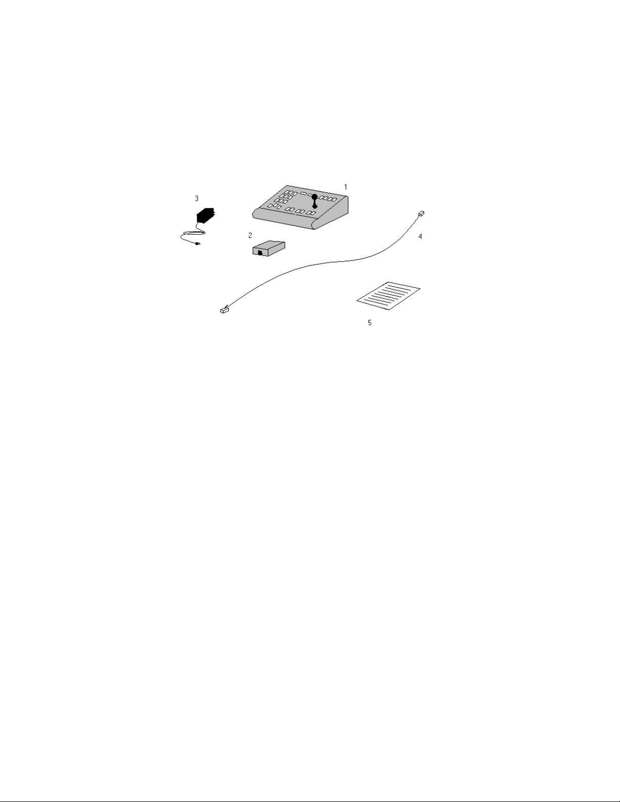
Box Content.
The JK-UC1 is delivered in a box that must include the following items:
1. A JK-UC1 unit
2. A wall block
3. A power supply
4. A 2 meters long UTP cable. Both ends must have a male RJ-45 connector attached
5. A quick reference guide
6. A Manual (this one)
7. A plastic bag
Figure 1
The lack of any of the above mentioned items MUST be referred to the dealer as soon as possible.
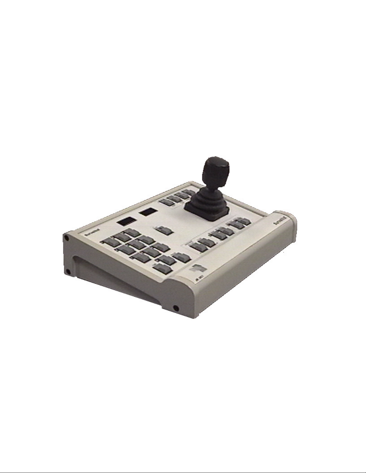
DESCRIPTION
The JK-UC1 Universal Controller was designed to control up to 255 Toshiba ‘P’ or Pelco ‘P’
compatible cameras directly wired to it. A special Switcher is needed to route video to the monitor.
The JK-UC1 has a 3-axis joystick that lets you control the zoom, pan and tilt positions of the
selected camera.
4
Page 5
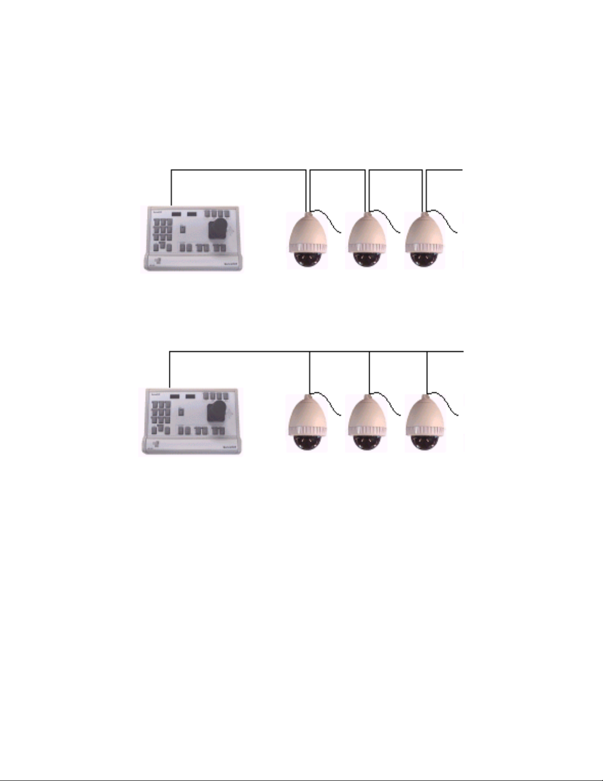
INSTALLATION
The JK-UC1 was created to be wired directly to a maximum of (32) receivers. This connections can
be done based upon a Daisy Chain Configuration (fig.1), a Star Configuration (fig. 2), or any
combination of the above. It is important to remember NOT to connect more than
(32) receivers in a
Star Configuration (parallel to one another).
Daisy Chain
Figure 2
Bus Configuration
Figure 3
The installation requires a video switcher to route the cameras output, and display it in a monitor.
5
Page 6
Connecting the JK-UC1
Prior to Installation
A location must be assigned to the unit. It must include:
1.
a. An energy plug, 110V AC, 60 Hz
b. The camera cables must end in a wall of the room
c. A desk or table to place the unit
d. A monitor to display the cameras output
e. A video switcher
2. The cameras installation must include assigning to them a non conflicting address
sequence and configuring each one of them according to it.
3. Every receiver must be configured to receive RS–422 / RS–485 communication suitable to
Toshiba ‘P’ or Pelco ‘P’ protocol (4800 bps, 8,1,1,n)
Installation
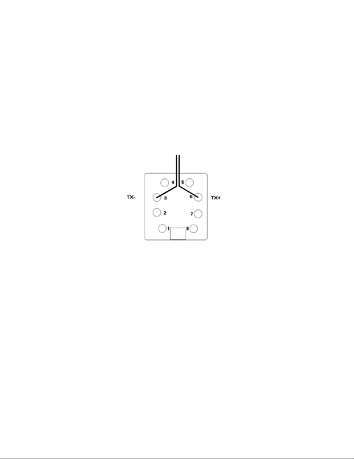
1. Remove the cover of the wall block and screw it to the wall, or attach it using the 2–sided
sticker.
2. Wire the transmission wires into pins 3(TX-) and 6(TX+). See fig.3.
Figure 4
3. Place the JK-UC1 unit in its assigned location. It is recommended for them not to be farther
than 2 meters (to be plugged with the cable included in the kit), but this is not needed. In
other cases, the cable is a standard one–to–one UTP cable ended on both sides in RJ–45
connectors. It is important for the data and power cables not to be stretched or stressed.
4. Replace wall block cover.
5. Refer to the Jumper Setting Section to define the configuration of the unit.
6. Plug the UTP cable into the RS–485 Communication Port, as shown in fig. 4
7. Plug the other end of the UTP cable into the wall block.
8. Plug in the power source and its connector in the rear of the unit.
9. Wait until the Initialization Procedure ends.
Note
Remember to turn on the video router unit, to display any image in the monitor.
6
Page 7

Figure 5
Jumper Settings
In a RS–485 connection, there are two types of receivers: the master and any amount of slaves.
The JK–UC1 was built and preconfigured to act as a master unit. If this is the case, no modifications
must be done whatsoever.
However, if the unit is going to act as a slave unit in the RS–485 line, every jumper on the A group
must be taken off. Refer to fig. 5.
In case the unit is going to use a RS–232 communication line, the jumpers on the B group must be
changed to the left side, as shown in fig 6. This is the case when trying to communicate the unit and
a PC. In case the communication would be RS-485, no change is needed.
Figure 6
7
Page 8

Figure 7
8
Page 9

JK-UC1 Operation
The JK-UC1 has the ability to control Toshiba-TAIS cameras , as well as any Toshiba ‘P’ or Pelco
‘P’ compatible dome camera.
For doing so, the controller has 23 keys, a joystick and two displays, as shown in fig. 7. Refer to this
figure or straight to the keyboard from now and on to relate to the functions of the unit. It is strongly
recommended to practice every function several times to get used to the operation of the system.
To simplify operations, the JK-UC1 has shortcuts to access each of those modes, even though it
keeps the Pelco procedure to access them. From this point and on, this manual will describe the
shortcuts to access the different commands. At the end of this section there is a cross reference
table to the alternative methods to access them. A regular Pelco user can feel free to use the way
he or she is used to operate the controller.
9
Page 10

10
Page 11

Menu Mode
Some special functions of the domes are reserved to be accessed through a MENU mode.
To get to this mode the JK-UC1 uses the following sequence:
1. Type down “95” on the number keypad.
2. Press the Preset key. This is equivalent to access the Preset number 95. The JK-UC1 will present
“Menu” on the right display for a moment, the display will go back to show the selected camera
number and the image of the camera will present the menu on the monitor screen.
3. To move in the menu:
a. To move use the Joystick
b. To select an option, use IRIS IN.
c. To exit of an option (or go back to the previous menu screen) use IRIS OUT.
The available options are shown in each domes manual.
Clear Command
In any situation of a error while entering a command sequence, the CLEAR key can be pressed. It
will abort any undone command, it will return to the regular condition, ready to accept a new
command.
Camera Selection
Since the controller can operate up to 255 cameras, the first operation you need to use is the ability
to select the camera you desire.
Procedure
On start up, the unit will always select automatically the camera 001.
1. Using the number keypad, input the number of the camera you intend to use.
2. In case of any mistake in the input number, press the CLEAR and start the input again.
3. Once the number of the camera appears on the left display, press CAMERA key. The
controller will display “Cam” on the right side for a moment and then will come back to the
normal display situation.
Example
If the unit has the camera 23 selected, and you want to select camera number 125:
1. Input “1”, then “2” then “5” in the number keypad. The display will show “125 023”
2. Press CAMERA key. The unit will display “125 Cam” and the “Cam 125”
From now on, the selected camera is number 125.
Camera Special Functions
• To control Focus the controller has specially assigned keys, called FOCUS IN and FOCUS
OUT.
• To control the IRIS IN and IRIS OUT.
• To control ZOOM IN rotate the joystick knob clockwise and for ZOOM OUT, rotate it
counter clockwise.
Back Light Compensation
To ACTIVATE or DEACTIVATE this option, press BACKLIGHT ON/OFF key.
Next time you press it, it will produce the opposite command.
Example
If Back Light Compensation is ON:
Press the BACKLIGHT ON/OFF key. The controller will change it to OFF.
If Back Light Compensation is OFF press the BACKLIGHT ON/OFF key and it will turn it ON.
AF Trigger
The Auto Focus feature can be activated and deactivated by following this procedure:
1. Press the Shift key, so that the light in it turns on.
2. Press the Focus IN key. The JK-UC1 will display “AF” on the right display for a moment.
After that, the result of the sequence will be seen in the screen and the displays will go back
to show the selected camera number.
11
Page 12

WB Trigger
The White Balance feature can be activated and deactivated by following this procedure:
1. Press the Shift key, so that the light in it turns on.
2. Press the IRIS IN key. The JK-UC1 will display “W/B” on the right display for a moment.
After that, the result of the sequence will be seen in the screen and the displays will go back
to show the selected camera number.
12
Page 13

IR Filter
Even though not all cameras have the IR filter feature, the Toshiba ‘P’ protocol includes a
command for using this feature, which is implemented in the JK-UC1 controller. To
activate it follow this sequence:
1. Press the Shift key, so that the light in it turns on.
2. Press STOP[F1] function key. The JK-UC1 will display “IR F” on the right display for a
moment. After that, the result of the sequence will be seen in the screen and the displays
will go back to show the selected camera number.
Version
In case you would need the version and description of a dome, and if it has the option, the
JK-UC1 can request for it, following this sequence:
1. Press the Shift key, so that the light in it turns on.
2. Press the FOCUS OUT key. The JK-UC1 will display “Ver” on the right display for a
moment. After that, the result of the sequence will be seen in the monitor and the displays
will go back to show the selected camera number.
Scanning Functions
There are five kinds of scanning functions implemented in the JK-UC1, according to the
amount of functions that could be included in your dome:
• Auto Scan,
• Auto Patrol,
• Random Scan
• Frame Scan.
• Pattern
The definition of each one is in each dome’s manual. To stop any of these scanning
procedures just press the STOP key.
To activate each of these dome procedures, just press the key named by it:
Auto Scan
Press the Auto Scan key(F2) . The right display will present the text “AScn”
Random Scan
Press the Random Scan key(F3) . The right display will present the text “RScn”
For Auto Patrol
Press the Auto Patrol key (F4). The right display will present the text “Ptrl”
Frame Scan
1. Press Shift key until its light turns ON.
2. Press Auto Patrol[F4]. The right display will present the text “FScn”
Pattern
3. Press Shift key until its light turns ON.
4. Press Random Scan[F3]. The right display will present the text “Patt”
13
Page 14

Scan Limits
With any of the scan processes the domes use STOPS. Refer to the proper dome manual to find out more
about this subject.
Using the JK-UC1 to define the STOPS, you have to follow this sequence:
1. Using the Joystick move to the position at which you want to set the STOP.
2. Define if this position is going to be the Right Scan Limit or the Left one.
3. To set the Right Scan Limit:
a. Type down “93” using the number keypad.
b. Press “Preset” The JK-UC1 will display “RLm” on the right display for a moment. After
that, the STOP is set and the displays will go back to show the selected camera number.
4. To set the Left Scan Limit:
a. Type down “92” using the number keypad.
b. Press “Preset” The JK-UC1 will display “LLm” on the right display for a moment. After
that, the Stop is set and the displays will go back to show the selected camera number.
Through out the manual scanning process, the user may be restricted to look at certain
areas. To do so, the Right Manual Scan STOP and the Left Manual Scan STOP must be set.
In that case, follow the next procedure:
1. Using the Joystick move to the position at which you want to set the STOP.
2. Define if this position is going to be the Right Scan Limit or the Left one.
3. To set the Right Manual Scan Limit:
c. Type down “91” using the number keypad.
d. Press “Preset” The JK-UC1 will display “RMLm” on the right display for a moment. After
that, the Stop is settled and the displays goes back to show the selected camera number.
4. To set the Left Manual Scan Limit:
e. Type down “90” using the number keypad.
f. Press “Preset” The JK-UC1 will display “LMLm” on the right display for a moment. After
that, the Stop is settled and the displays goes back to show the selected camera number.
Patterns
Patterns are command sequences that repeat what the user would do in a certain situation. There are two
commands that need to be send to act in this direction:
- START saving the procedure,
- STOP saving the procedure.
Start Pattern
g. Type down “266” using the number keypad.
h. Press “Preset” The JK-UC1 will display “PStr” on the right display for a moment. After
that, the Stop is settled and the displays goes back to show the selected camera number.
End Pattern
i. Type down “267” using the number keypad.
j. Press “Preset” The JK-UC1 will display “PStp” on the right display for a moment. After
that, the Stop is settled and the displays goes back to show the selected camera number.
14
Page 15

Preset Functions
Set Preset
Domes are able to store several preset positions (in the case of the Toshiba TAIS units, 64
of them). The procedure to define this presets is as follows:
1. Assign a number to it. Remember, if the number is already in use, the previous preset can be erased
or there will be an error, depending on the dome.
2. Type down the selected number using the number keypad.
3. Press the Shift key, so that the light in it turns on.
4. Press the Preset key. The JK-UC1 will display “SetP” on the right display for a moment. After that,
the preset is set and the displays will go back to show the selected camera number.
Clear Preset
To clear a Preset follow the next sequence:
1. Type down the number of the Preset you want to erase using the number keypad.
2. Press the Shift key, so that the light in it turns on.
3. Press the Auto Scan[F2] key. The JK-UC1 will display “ClrP” on the right display for a moment.
After that, the preset is erased and the displays will go back to show the selected camera number.
Go to Preset
To go to a Preset follow this sequence:
1. Type down the number of the preset you want to go to, using the number keypad.
2. Press the Preset key. The JK-UC1 will display “PrSt” on the right display for a moment. After that,
the dome will go to the selected preset and the displays will go back to show the selected camera
number.
Special Presets.
• Both the Toshiba ‘P’ and Pelco ‘P’ protocols define that there is a Home position,
which is in Preset number 100. To go there, just select Preset number 100 as
described in “Go to Preset” section. The JK-UC1 will present “Home” on the
right display for a moment, the dome will start moving to the initial position,
and the display will go back to show the selected camera number.
• It is also defined in both protocols that to rotate in 180º you simply select Preset
number 120 as described in “Go to Preset” section. The JK-UC1 will present “Flip”
on the right display for a moment, the dome will flip, and the display will go back to
show the selected camera number.
15
Page 16

Advanced Procedures
Remote Reset
In case of need, the JK-UC1 can send a RESET Command to the dome camera. To do so go
to Preset number 257.
Soft Reset for the JK-UC1
In case of need, the JK-UC1 can be reset by going to the Preset number 258. This
procedure runs the initial sequence, clears all buffers and starts anew.
16
Page 17

SPECIFICATIONS
GENERAL
• 23 Keys Keyboard of highly durable buttons.
• Joystick: 3-axis, vector-solving, with twisting, return-to-center head
• Digital Display: 2 displays, 4 byte each, 7X5 LED characters
• Shift Key including an Indicator: Green LED
Ambient Operating
• Temperature: 20º to 120ºF (-7ºto +49ºC)
• Humidity: 10–90% non-condensing
ELECTRICAL
• Input Voltage: 9 VAC or 9 VDC
• Power Consumption: 2 watt
• Connector Type: RJ-45, 8-pin, modular (female)
Keyboard Communication
• Interface: RS-485
• Protocol: Toshiba P, Pelco P
• Baud Rate: 4800 bps
• Communication Parameters: Parameters: 8 data bits, odd parity, 1 stop bit
Others
• Weight: 5.9 Pounds [2.2 Kg]
• Length : 10.6 in [270 mm]
• High : 5.0 in [127.5 mm]
Depth :
17
 Loading...