

Page 1

Document: OH01
Phone: 800.894.0412 - Fax: 888.723.4773 - Web: www.clrwtr.com - Email: info@clrwtr.com
Issued:
TOSHIBA
INSTRUCTIONS
OPERATION MAINTENANCE
JK Medium Voltage Controllers Maximum
Page 2

INTRODUCTION
Phone: 800.894.0412 - Fax: 888.723.4773 - Web: www.clrwtr.com - Email: info@clrwtr.com
READ THIS MANUAL carefully for important information about safety, handling, and
maintenance, for general-purpose NEMA Class E magnetic controllers.
This manual and all accompanying drawings should be considered a permanent part of the
equipment. They should be readily available for review and reference at all times.
DIMENSIONS shown in the manual are in metric and/or their English equivalent.
These instructions are not intended to cover all details, combinations, or variations of the
equipment, storage, or installation.
PROBLEMS OR QUESTIONS should be addressed to:
Field Service Department
Toshiba International Corporation
13131 West Little York Road
Houston, Texas 77041 USA
Telephone:
FAX: (713) 466-8773
466-0277
(800) 231-1412
(800) 527-l 204 (Canada)
Page 1
Use only Toshiba-authorized replacement parts.
This equipment is designed and built in accordance with applicable
safety standards in effect on the date of manufacture. Unauthorized
modifications can result in severe injury, death and property damage.
Do not make any modifications to this equipment without the written
approval of Toshiba.
TOSHIBA INTERNATIONAL CORPORATION, 1994
Page 3

Page 2 TABLE OF CONTENTS
Phone: 800.894.0412 - Fax: 888.723.4773 - Web: www.clrwtr.com - Email: info@clrwtr.com
Page
SAFETY . . . . . . . . . . . . . . . . . . . . . . . . . . . . . . . . . . . . . . . . . . . . . . . . . . . . . . . . . . . . . 4
RECEIVING AND HANDLING . . . . . . . . . . . . . . . . . . . . . . . . . . . . . . . . . . . . . . . . . . . . . . . 7
Receiving and Unpacking ............................................
Handling and Moving ...............................................
Using a Forklift ...................................................
Overhead Lifting ..................................................
Contactor Carriage Handling ..........................................
STORAGE . . . . . . . . . . . . . . . . . . . . . . . . . . . . . . . . . . . . . . . . . . . . . . . . . . . . . . . . . . .
Preparation ..................................................... 10
Indoor Equipment ................................................. 10
Outdoor Equipment ............................................... 10
Routine Inspection ................................................
GENERALDESCRIPTION................................................. 12
Construction .................................................... 12
Controller Compartment ............................................
Isolation Switch .............................................
Withdrawable Contactor Carriage ................................. 14
Service Drawer
Load Receptacle and Current Transformers .......................... 15
Outgoing Load Connections ..................................... 16
Control Power Transformer ..................................... 18
Operating Handle ............................................ 19
Interlocks
Interlocks
Low Voltage Compartment .......................................... 22
Main Bus Compartment ............................................ 22
Prepared Spaces ................................................. 23
Contactor Ratings ................................................ 24
Controller Ratings ................................................ 25
Horsepower Table ................................................ 26
Mechanical ........................................ 19
Door Interlock ......................................... 19
Handle Interlock ........................................ 20
Vacuum Contactor Interlock ............................... 20
Electrical .........................................
Control Power Interlock
Test Power Interlock .................................
.............................................
...............................
1 0
11
15
21
21
21
7
7
8
8
9
INSTALLATION . . . . . . . . . . . . . . . . . . . . . . . . . . . . . . . . . . . . . . . . . . . . . . . . . . . . . . . 27
Rating Verification ................................................ 27
Location ....................................................... 27
Service Conditions ................................................ 27
Installation Site Preparation .......................................... 28
Mounting ...................................................... 28
Page 4

TABLE OF CONTENTS
Phone: 800.894.0412 - Fax: 888.723.4773 - Web: www.clrwtr.com - Email: info@clrwtr.com
Grounding ......................................................
Connections .................................................... 31
Incoming Line ................................................... 33
Outgoing Load ...................................................
PRE-ENERGIZATIONCHECK . . . . . . . . . . . . . . . . . . . . . . . . . . . . . . . . . . . . . . . . . . . . . . 34
Page 3
Page
29
33
General ........................................................
Wiring.. ....................................................... 35
Devices
Electrical Checks ................................................. 37
OPERATION . . . . . . . . . . . . . . . . . . . . . . . . . . . . . . . . . . . . . . . . . . . . . . . . . . . . . . . . .
Contactor Installation .............................................. 38
Initial Energization ................................................ 39
MAINTENANCE . . . . . . . . . . . . . . . . . . . . . . . . . . . . . . . . . . . . . . . . . . . . . . . . . . . . . . . 41
Maintenance Record ...............................................
General Inspection ................................................ 42
Electrical Joints .................................................. 43
Contactor Carriage ................................................
Isolation Switch ..................................................
Switch Handle Mechanism .......................................... 45
Interlocks ...................................................... 46
Load Receptacle ..................................................
Control Power Transformer .......................................... 47
MAINTENANCE AFTER A FAULT CONDITION . . . . . . . . . . . . . . . . . . . . . . . . . . . . . . . . . . 48
Mechanisms .............................................
34
36
38
41
43
44
46
Enclosure ...................................................... 48
Isolation Switch ..................................................
Fuse Clips ...................................................... 48
Terminals and Internal Conductors ..................................... 48
Overload Relays ..................................................
Vacuum Contactor ................................................
Return to Service ................................................. 49
WARRANTY AND LIMITATION OF LIABILITY . . . . . . . . . . . . . . . . . . . . . . . . . . . . . . . . . . 50
48
48
49
Page 5

Page 4
Phone: 800.894.0412 - Fax: 888.723.4773 - Web: www.clrwtr.com - Email: info@clrwtr.com
IMPORTANT MESSAGES
Read this manual and follow its instructions. Signal words such as DANGER, WARNING
and CAUTION will be followed by important safety information that must be carefully
reviewed.
NOTE Gives you helpful information
SAFETY
Indicates a situation which will result in death, serious injury, and severe
property damage if you do not follow instructions.
means that you might be seriously injured or killed if you do not follow
instructions. Severe property damage might also occur.
means that you might be injured if you do not follow instructions.
Equipment damage might also occur.
READ SAFETY SIGNS
To avoid injury,
You must read and follow
all safety signs.
Keep the safety signs visible
and in good shape. Never
remove or cover any safety signs.
DANGER
NOT REMOVE. DESTROY OR THIS LABEL I
READ THE INSTRUCTION MANUAL CAREFULLY BEFORE
INSTALLING, THIS
HAZARDOUS VOLTAGE In This Compartment.
I I Cause Injury, Death, Fire,
Exp I
! Turn Off And Lock Out Pr mat-y And
! Door Unless Isolation
! Keep A I I Panels And Covers
! Never Defeat, O r Bypass
! Dual if Operators Only.
And Property Damage.
I Circuit Power Servicing
Switch
In Place.
Safety Inter locks
OFF And Contactor Is OPEN.
Safety sign on front cover of
controller unit.
Page 6

SAFETY
Phone: 800.894.0412 - Fax: 888.723.4773 - Web: www.clrwtr.com - Email: info@clrwtr.com
QUALIFIED OPERATORS ONLY
Only qualified persons are to install, operate, or service this equipment according to all
applicable codes and established safety practices.
A qualified person must:
Page 5
Carefully read the entire instruction manual.
Be skilled in the installation, construction or operation of the equipment and aware
of the hazards involved.
Be trained and authorized to safely energize, deenergize, clear, ground, lockout and
tag circuits in accordance with established safety practice.
Be trained and authorized to perform the service, maintenance or repair of this
equipment.
Be trained in the proper care and use of protective equipment such as rubber
gloves, hard hat, safety glasses, face shield, flash clothing, etc. in accordance with
established practices.
Be trained in rendering first aid.
SAFETY CODES
Toshiba medium voltage controllers are general purpose, Class E, magnetic controllers
designed and built in accordance with the latest applicable provisions of NEMA ICS 2-324,
UL 347 and the National Electrical Code. Installations must comply with all applicable
state and local codes, adhere to all applicable National Electric Code
and instructions provided in this manual.
standards
Page 7

Page 6
Phone: 800.894.0412 - Fax: 888.723.4773 - Web: www.clrwtr.com - Email: info@clrwtr.com
SAFETY
HAZARDOUS VOLTAGE will cause severe injury, death, fire, explosion and
property damage.
Turn off and lock out Primary and Control Circuit Power before servicing.
Do not open door unless Isolation Switch is OFF and Contactor is OPEN.
Keep all panels and covers securely in place.
Never Defeat, Modify, or Bypass any Safety Interlocks
Qualified Operators only
Page 8
RECEIVING AND HANDLING
Phone: 800.894.0412 - Fax: 888.723.4773 - Web: www.clrwtr.com - Email: info@clrwtr.com
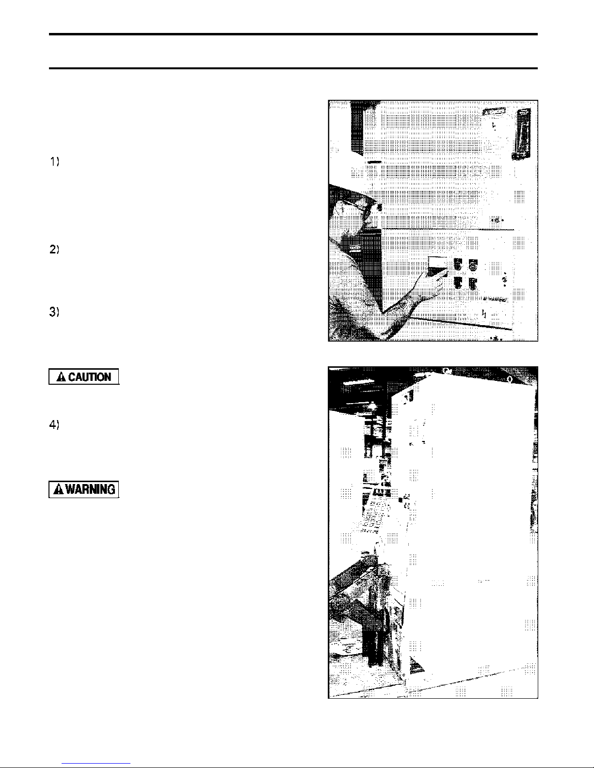
RECEIVING AND UNPACKING
Upon receipt of the equipment, do the
following:
Make an immediate inspection for any
damage which might have occurred
during shipment (Fig. 1). If damage is
found, it should be noted with the
carrier prior to accepting the shipment,
if possible.
Carefully unpack the equipment
sufficiently to check for concealed
damage and to determine that the
shipment is complete and correct.
Keep the equipment upright. If the
controller is not upright upon receipt,
notify the carrier of possible damage.
Upright the unit as soon as possible.
Page 7
Fig. 1 Inspect The Controller
Do not lay the equipment
on its side or upside
down.
File a claim with the carrier for any
damaged or missing item and
immediately notify the nearest Toshiba
Representative.
Do not install or energize
equipment that has been
damaged.
HANDLING AND MOVING
Medium voltage motor controllers should be
handled with care, t o avoid damage to
components and to the frame or its finish
(Fig. 2).
The capability of the moving equipment to
handle the weight of the controller shipping
section should be confirmed.
The equipment should remain secured to the
shipping skid to prevent distortion of the frame
during moving and to minimize tipping.
Extreme care should be exercised during any
Fig. 2 Moving The Controller
Page 9

Page 8
Phone: 800.894.0412 - Fax: 888.723.4773 - Web: www.clrwtr.com - Email: info@clrwtr.com
movement and placement operations to
prevent dropping, or tipping.
Do not place any part of
your body beneath
equipment being lifted.
Improperly secured
equipment can fall or tip
over quickly and without
notice.
Do not attempt
installation or removal of
the contactor carriage
using the lifting methods
described in this section.
Always use a Toshiba JK
LIFTING DEVICE for the
installation or removal of
the contactor carriage.
USING A FORKLIFT
RECEIVING AND HANDLING
Fig. 3 Use of Spreader Bar-Single Section
A forklift truck may offer a more convenient
method of handling the controller. A safety
strap should be used when handling with a
forklift. The ends of the forks should not enter
the bottom of an open-bottom enclosure.
OVERHEAD LIFTING
When it is necessary to move the equipment
between elevations, overhead hoisting may be
required. Lifting angles (for multiple controller
sections) are provided on top of the enclosure
for this purpose.
Spreaders (Fig. 3) should be used to provide
the vertical lift on single controllers to prevent
eye-bolt failure.
Always keep the controller upright while lifting.
Some controller sections may contain heavy or
special equipment that will cause the center of
gravity to be off-center. Rigging lengths
should be adjusted to maintain the controller in
an upright position. The angle between the
lifting cables and vertical should not be
allowed to exceed 45 degrees (Fig. 4). Ropes
or cables should not pass through the holes in
LIFT
Fig. 4 Lifting Multiple Sections
Page 10

RECEIVING AND HANDLING
Phone: 800.894.0412 - Fax: 888.723.4773 - Web: www.clrwtr.com - Email: info@clrwtr.com
Page 9
lifting angles or eye-bolts. Slings with safety
hooks or shackles of adequate
should be used.
CONTACTOR CARRIAGE
GENERAL DESCRIPTION, page
normally shipped inside their respective
controller compartments. During initial
installation, the contactor carriages must be
removed from their compartments to allow
access for anchoring the enclosure to the floor,
and for pulling and terminating load cables.
Removal of the contactor carriage is facilitated
by the use of a Toshiba JK carriage lifting
attachment (Fig.
lifting device. The lifting attachment is
furnished with all JK medium voltage
controllers.
Details on the operation of the service drawer
which supports the contactor carriage may be
and a suitable overhead
load rating
NG
(refer toWithdrawable contactor carriage
are
found in the OPERATION section, page 38.
Two shipping brackets securing the carriage to
the service drawer must be removed before
attempting to lift the carriage from the drawer.
These brackets are used only for transportation
and may be discarded.
To attach the lifting attachment to the
carriage:
1.
2.
3.
4.
Position lifting attachment on top of
carriage.
Swing side support arms down to meet
carriage base.
Securely screw lift bolts into base.
Attach overhead lifter to eye bolt on
top of lifting attachment and lift from
drawer.
Maximum weight of
is
carriage
equipped with double
barrel fuses. Verify that
lifter used as adequate
load capacity.
135 Ibs
LIFTER HERE
Fig. 5 Contactor Carriage Lifting Attachment
Page 11

Page 10 STORAGE
Phone: 800.894.0412 - Fax: 888.723.4773 - Web: www.clrwtr.com - Email: info@clrwtr.com
PREPARATION
If the controller is to be stored for any length
of time prior to installation, the packing should
be restored for protection during that period.
Where conditions permit, the packing should
be left intact until the controller is at the final
installation position. If the packing (Fig. 6) is
removed, the top and openings of the
controller should be covered during the
construction period to protect it against dust
and debris.
INDOOR EQUIPMENT
Controllers designed for indoor installation
(NEMA Type 1, 12) which are not to be
installed and energized immediately, should be
stored in a clean, dry space where a uniform
temperature prevents condensation.
Preferably, the controller should be stored in a
heated building, with adequate air circulation
and protected from dirt and water. Equipment
should be stored where it is not subject to
mechanical damage, especially during building
construction.
An indoor controller that is to be stored
outdoors should be securely covered for
protection from weather conditions and dirt.
Temporary electrical heating should be
installed to prevent condensation.
Approximately 150 watts per enclosure is
usually adequate.
NOTE:
materials should be removed before energizing
space heaters.
OUTDOOR EQUIPMENT
An unenergized controller designed for outdoor
installation (NEMA Type
etc.) should be kept dry internally by installing
electrical heating or by energizing self-heaters,
if provided.
All openings, either used or unused should be
covered or sealed to prevent the entry of rain,
vermin, insects, etc.
All loose packing or flammable
EPIC building,
Fig. 6 Storage
Page 12

STORAGE Page 11
Phone: 800.894.0412 - Fax: 888.723.4773 - Web: www.clrwtr.com - Email: info@clrwtr.com
ROUTINE INSPECTION
Routine scheduled inspection should be
established if storage for an extended period is
anticipated. This is to check for condensation,
corrosion, vermin, and adequacy of space
heating.
Prior to inspection, the equipment should be
carefully examined for evidence of physical
damage, corrosion, or other deterioration.
Do not install equipment
found to have damage or
deterioration that could
affect the unit
performance.
Page 13
Page 12
Phone: 800.894.0412 - Fax: 888.723.4773 - Web: www.clrwtr.com - Email: info@clrwtr.com
Toshiba medium voltage controllers are AC
general-purpose NEMA Class E controllers
designed for applications at utilization voltages
ranging from 2.3 through 6.6
normally used to control motor loads, although
other types of loads such as transformers and
capacitors are possible.
CONSTRUCTION
They are
GENERAL DESCRIPTION
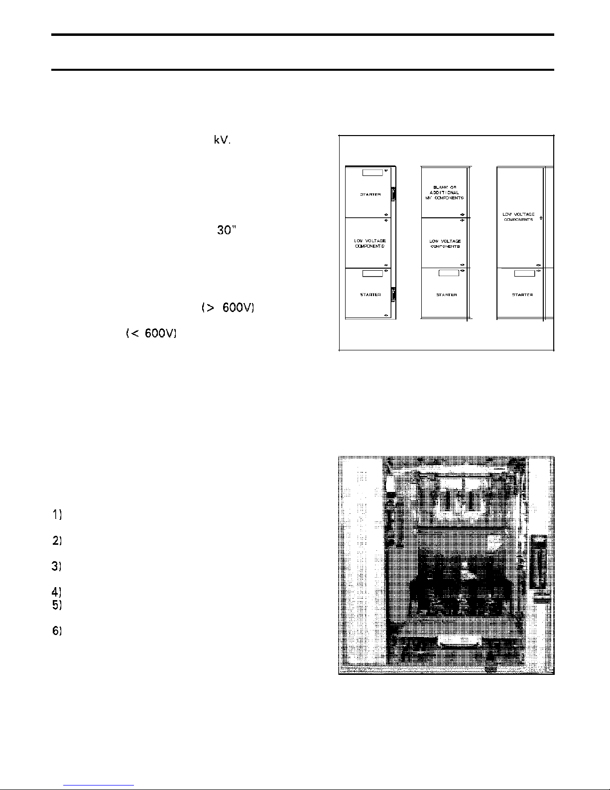
The standard enclosure size is
36” deep by 90” high. In a typical two-high
arrangement, each enclosure is divided
vertically into three major compartments, each
with a separate door. The uppermost and
lowermost compartments contain medium
voltage controller components
the middle compartment contains low voltage
components
variations of this basic arrangement are
possible.
Main horizontal bus is provided when required
to supply power to a line-up of controllers.
The main bus is located at the rear of the
enclosure midway between the top and
bottom. A common ground bus is also
provided for multiple sections.
Each controller compartment (Fig. 8) consists
of:
Fixed mounted non-load break isolation
switch.
Withdrawable contactor carriage with
power fuses.
Built-in service drawer for removing
contactor carriage from compartment.
Current transformers for metering.
Control power transformer and optional
potential transformer.
Load cable terminations.
(Fig. 7). Other
wide by
while
Fig. 7 Typical Controller Arrangements
Fig. 8 Controller Compartment
Page 14

GENERAL DESCRIPTION
Phone: 800.894.0412 - Fax: 888.723.4773 - Web: www.clrwtr.com - Email: info@clrwtr.com
CONTROLLER COMPARTMENT
Page 13
A.
Power is switched on and off to each
individual controller compartment by a
mounted, externally-operated, three-pole
isolation switch. When the switch is in the
open position, incoming power is isolated from
the compartment interior by an automatic
shutter. Also, the load terminals of the switch
are automatically grounded in the open
position for additional safety.
The isolation switch is designed to accept a
direct connection from the line stabs of the
withdrawable contactor carriage.
connection is automatically made when the
contactor carriage is installed in the medium
voltage compartment.
closed by operating the external handle,
incoming power is applied to the line side of
the power fuses. In this position, the motor or
other load may be switched on and off by
operating the vacuum contactor.
Isolation Switch (Fig. 9)
This
When the switch is
Fig. 9 Isolation Switch
is
The isolation switch
interlocked with the vacuum contactor and the
compartment door. Details of the interlocking
are discussed in section H.
The position of the isolation switch blades can
be observed through a window in the medium
voltage compartment door. Thus, it is possible
to have visual evidence that the power source
is isolated before entering the medium voltage
compartment. The switch is also provided
with lock-out provisions (Fig. IO).
The isolation switch has a maximum
interrupting capacity of 0.4 amperes.
Do n o t connect
additional load to the
isolation switch.
mechanically
Fig. 10 Isolation Switch Lockout
Page 15
Page 14
Phone: 800.894.0412 - Fax: 888.723.4773 - Web: www.clrwtr.com - Email: info@clrwtr.com
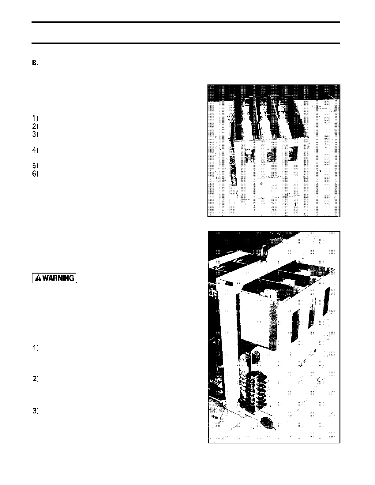
Withdrawable Contactor Carriage
(Fig. 11)
The withdrawable contactor carriage is a
removable assembly which contains the
following components:
Vacuum contactor
Power fuse housing assembly.
Set of line and load power stab
terminals.
Auxiliary contacts for vacuum
contactor.
Control wiring disconnect plug.
Set of wheels to facilitate moving the
is
carriage when it
controller.
The withdrawable contactor carriage is
normally shipped installed in the controller. It
may be removed for access to the medium
voltage compartment during initial installation,
connection of motor cables, etc. Periodically,
removal of the carriage may also be necessary
for routine maintenance of the contactor or
replacement of the power fuses.
outside the
GENERAL DESCRIPTION
Fig. 11 Withdrawable Contactor Carriage
Always use a Toshiba JK
Lifting Device (Fig. 12)
for removal or installation
of the contactor carriage.
When the carriage is installed in the controller
compartment, the following connections are
automatically made:
The line side stabs engage the fixed-
mounted isolation switch connecting
the load side of the switch to the line
side of the power fuses.
The load side stabs engage the fixed-
mounted load receptacle connecting the
load side of the vacuum contactor to
the current transformers.
The control transformer primary stabs
engage fixed-mounted clips connecting
the load side of the power fuses to the
primary side of the control
transformer(s).
Fig. 12 Lifting Device
Page 16
GENERAL DESCRIPTION
Phone: 800.894.0412 - Fax: 888.723.4773 - Web: www.clrwtr.com - Email: info@clrwtr.com
In addition, when the withdrawable contactor
is
carriage
compartment, it becomes interlocked with the
isolation switch so that the switch may not be
opened or closed unless the contacts of the
vacuum contactor are opened.
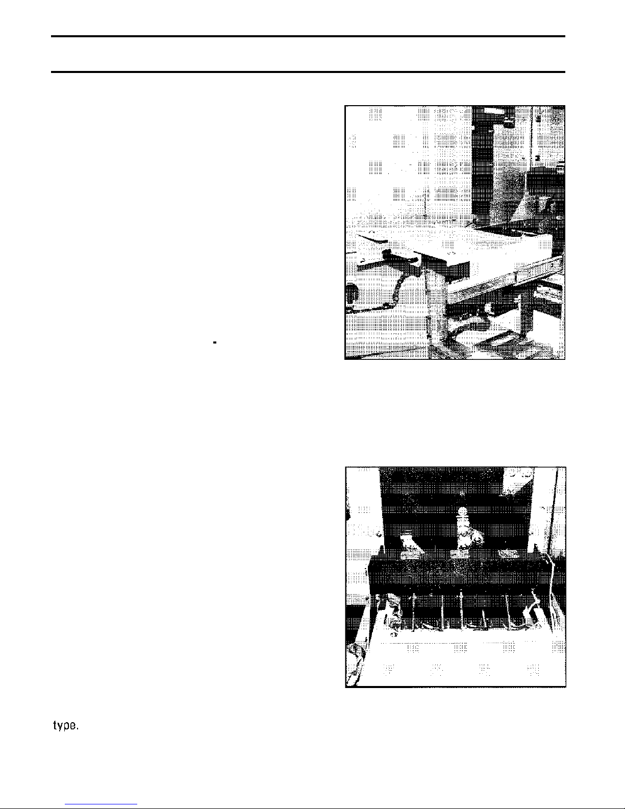
C. Service Drawer (Fig. 13)
The withdrawable contactor carriage is moved
in and out of the controller compartment on a
built-in sliding service drawer. The drawer has
four locating pins on top of it. When the
contactor carriage is placed on the drawer,
these pins engage four holes in the bottom of
the carriage which serve to align it properly.
The drawer moves in and out of the controller
compartment on sliding ball
rails. There is a handle on the front of the
drawer to provide a gripping point.
inserted into the controller
bearing type
Page 15
Fig. 13 Service Drawer
D.
The load receptacle is a fixed three-phase
disconnecting block. The vacuum contactor
load stabs on the withdrawable carriage
engage the load receptacle when the carriage
is installed in the controller compartment.
The load receptacle uses bolted pressure type
stab contacts similar to those used in the
isolation switch.
The operation of the bolted pressure contact
mechanism in the load receptacle is controlled
by a release lever located at the front of the
compartment be low t he ser vic e drawer.
Further details on the operation of the release
lever can be found in the OPERATION section
of this manual.
Power from the load receptacle is fed through
three current transformers located just behind
it. Current transformers furnished may be
either wound primary (bar) type, or window
Load Receptacle and Current
Transformers (Fig. 14)
Fig. 14 Load Receptacle
Page 17

Page 16 GENERAL DESCRIPTION
Phone: 800.894.0412 - Fax: 888.723.4773 - Web: www.clrwtr.com - Email: info@clrwtr.com
E.
Outgoing Load Connections
Connections for outgoing load cable are
located at the rear of each controller
compartment just above the current
transformers. Cables may enter the controller
from either the top or bottom of the enclosure
through the
provided.
If no specific information is provided when the
equipment is ordered regarding the type of load
cables to be used and the direction of entry,
the standard termination assembly shown in
Fig. 15 and Fig. 16 is supplied. Non-shielded
cables sized up one 350MCM per phase can be
accommodated entering either from the top or
bottom of the enclosure (Fig. 15).
This
arrangement can also accept shielded cables
entering from the top sized up to one
350MCM per phase (Fig. 16).
Space is
provided for installation of termination kits
(stress cones) and user-supplied one- or
hole compression type connectors.
Fig. 15
EXIT CABLES
MAX SIZE 350MCM NON-SHI
1
CABLE PER PHASE
BOTTOM EXIT CABLES
MAX
1 CABLE PER PHASE
350MCM NON-SHIELDED
Non-Shielded Cable Termination
When the installation requires termination of
shielded load cables entering from the bottom
of the enclosure, this should be specified when
the equipment is ordered and the termination
assembly shown in Fig. 17 is then provided.
This arrangement can accept shielded or non-
shielded cables up to one 350MCM per phase
entering from the bottom. A field conversion
kit is available to convert from the standard
termination assembly (Fig. 15 and Fig. 16) to
the arrangement shown in Fig. 17. Consult
your local sales representative for information
regarding this kit.
When routing and terminating load cables,
observe the following:
If a ground current sensor (optional)
is supplied with the equipment, route
all of the load cables through the
sensor. Ground wires from shielded
cable terminators must be routed back
through ground sensor window before
attaching to ground bus.
TOP EXIT CABLES
MAX SHIELDED
1 CABLE PER PHASE
SWITCH
Fig. 16 Shielded Cable Termination Top
Entry
Page 18

GENERAL DESCRIPTION
Phone: 800.894.0412 - Fax: 888.723.4773 - Web: www.clrwtr.com - Email: info@clrwtr.com
Use Listed compression connectors
suitable for the cable being used.
Page 17
Use the
the controller to attach cable
connectors to bus pads. After
installation, torque hardware to 45
ft.
After installation, check to see that at
least three inches clearance is
maintained between live parts of
opposite polarity and between live
parts and ground.
hardware provided with
Fig. 17 Shielded Cable Termination
Entry
Bottom
Page 19

Page 18
Phone: 800.894.0412 - Fax: 888.723.4773 - Web: www.clrwtr.com - Email: info@clrwtr.com
GENERAL DESCRIPTION
F.
A control power transformer (Fig. 18) is
mounted on the left-hand side wall of the
controller compartment. Power is supplied to
the fused primary of the control power
transformer from stabs on the withdrawable
contactor carriage. These stabs engage clips
on the transformer when the carriage is
inserted into the compartment.
Optionally, a second transformer (Fig.
normally used as an instrument transformer,
can be mounted in the compartment. When
this option is supplied, a third set of stabs is
furnished on the withdrawable carriage. The
two transformers are then connected in an
open-delta arrangement.
Another option sometimes supplied is a second
control power transformer connected in parallel
with the first to increase the available KVA
capacity.
Control Power Transformer
Fig. 18 Control Power Transformer
Both the control and optional potential
transformer are used to supply power to the
low voltage circuits of the controller. This
includes power for the vacuum contactor
operating coil and for various instrumentation.
An electrical interlock is provided to ensure
that all load is disconnected from the control
power transformer secondary winding before
the power isolation switch can be opened or
closed.
Fig. 19 Optional Transformer
Page 20

GENERAL DESCRIPTION
Phone: 800.894.0412 - Fax: 888.723.4773 - Web: www.clrwtr.com - Email: info@clrwtr.com
G. Operating Handle
The external operating handle shown in Fig. 20
is used to control the operation of the isolation
switch. Moving the handle upward turns the
switch on, thus applying incoming power to
the current-limiting fuses on the withdrawable
carriage. The withdrawable contactor carriage
can neither be inserted nor removed when the
operating handle is in the “on” position.
Moving the handle down opens the isolation
switch, de-energizing all medium voltage
incoming power to the controller compartment.
At the same time an automatic shutter within
the switch closes providing an effective barrier
between the controller compartment and the
incoming supply. The opening of the switch
also causes the line side of the power fuses to
be grounded.
H. Interlocks Mechanical
Fig.
Page 19
Operating Handle
a.
A mechanical interlock is provided to prevent
opening or closing the medium voltage
compartment door unless the switch operating
handle is off (Fig. 21).
Door Interlock
Fig. 21 Door Interlock
Page 21

Page 20
Phone: 800.894.0412 - Fax: 888.723.4773 - Web: www.clrwtr.com - Email: info@clrwtr.com
GENERAL DESCRIPTION
b.
Two mechanical interlocks are provided to
prevent operating the switch
improperly.
The first interlock prevents moving the handle
from OFF to ON unless the compartment door
is closed (Fig. 22).
The second interlock prevents the switch
handle from being moved in either direction
unless the contacts of the vacuum contactor
on the withdrawable carriage are open
(Fig. 23).
C. Vacuum Contactor Interlock
The vacuum contactor is mechanically
interlocked to prevent it from closing unless
the switch handle is in the fully ON or fully
OFF position. The interlock shown in Fig. 23
provides this function.
Handle Interlock
handle
Fig.
Handle Interlock to Door
If the switch handle is in the intermediate
position, and a closing signal is given to the
contactor, it is mechanically prevented from
operating.
Fig. 23 Handle Interlock to Vacuum Contactor
Page 22

GENERAL DESCRIPTION Page 21
Phone: 800.894.0412 - Fax: 888.723.4773 - Web: www.clrwtr.com - Email: info@clrwtr.com
I.
a.
The control power interlock is a
microswitch which is directly driven by the
operation of the switch handle (Fig. 24). This
normally open switch is closed only when the
handle is fully ON.
disconnected from the control power
transformer secondary winding before the
isolation switch can be operated.
Interlocks Electrical
Control Power Interlock
It ensures that all load is
As the switch handle is moved from ON to
OFF, the CPI opens before the main contacts
of the power isolation switch. Conversely,
during closing of the switch, the CPI contacts
do not close until the switch contacts have
fully closed. The isolation switch is therefore
only subjected to making and breaking currents
equal to the no-load magnetizing current of the
transformer.
Fig. 24 Control Power Interlock
Do not connect any
additional load to the
isolation switch.
b.
The test power interlock is a scheme
provided to allow simulated operation of the
controller from a separate control power (test)
source with power removed from the medium
voltage circuit. During normal controller
operation with the isolation switch closed,
control power is fed from the control
transformer secondary to a receptacle mounted
on the low voltage
inserted into this receptacle, supplies power to
the controller’s low voltage compartment.
For testing purposes, the isolation switch must
be turned off and the controller door must be
opened. The plug is then removed and
inserted into an ordinary extension cord.
Plugging the extension cord into a conventional
outlet provides
control circuit operational tests while the
medium voltage circuit is de-energized.
Test Power Interlock
(Fig. 25). A plug,
power for performing
Fig. 25 Test Power Receptacle
Page 23

Page 22 GENERAL DESCRIPTION
Phone: 800.894.0412 - Fax: 888.723.4773 - Web: www.clrwtr.com - Email: info@clrwtr.com
LOW VOLTAGE COMPARTMENT
The low voltage compartment contains
controller components rated 600 volts
maximum. These may include such items as
overload relays, pilot devices, control relays,
The location and size of the low voltage
compartment will vary depending on the
particular controller arrangement. In a typical
two-high
compartment is located in the center of the
enclosure.
A
door which is used to mount various relays and
other devices. The
a way it can be swung open if necessary to
gain access to the main horizontal bus which
is located directly behind (Fig. 26).
controller, the low
is located behind the low voltage
Hazardous Voltage. Turn
off and lock out control
circuit power before
servicing.
voltage
is hinged in such
Hazardous Voltage. Turn
off and lock out all
control
power before opening
this panel.
and
primary
Fig. 26
Expose Main Bus
Low Voltage Opened to
Low voltage vertical
into the upper and lower left hand corners of
the low voltage compartment. A horizontal
low voltage
front of each low voltage compartment. At
each end of the horizontal
opening for inter-cubicle control wiring.
MAIN BUS COMPARTMENT
Main
throughout a line-up are located in an isolated
compartment located in the rear center of the
enclosure (Fig. 27). From the main bus, riser
bars supply power to each individual controller.
Standard main bus bars are copper with tin
plating. A copper ground bus is also located in
bus bars extending
is provided at the lower
feed directly
there is an
horizontally
Fig. 27 Main Bus Compartment
Page 24

GENERAL DESCRIPTION Page 23
Phone: 800.894.0412 - Fax: 888.723.4773 - Web: www.clrwtr.com - Email: info@clrwtr.com
the main bus compartment and is used to
provide a common ground point between
cubicles. Vertical ground riser bars extend
from the common ground bus into each
medium voltage controller compartment.
Access to the main bus compartment can be
obtained either by removing the enclosure back
sheet or by swinging open the hinged low
voltage
Bus splice links (Fig. 28) are furnished for
joining the main bus and ground bus between
shipping sections. With the low voltage
installed from the front of the unit. Refer to
Installation Section for details.
bpanel.
Hazardous Voltage. Turn
off and lock out all
control and primary
power before accessing
this compartment.
swung open, all splice links can be
PREPARED SPACES
Prepared spaces are compartments equipped
for future addition of controllers. Prepared
spaces are supplied with the following
components:
Isolation Switch
Service Drawer
Load Receptacle
In order to convert a prepared space to a
functional controller, the following must be
added:
contactor carriage
Handle mechanism for switch
Current transformers
Control power transformer
Fig. 28 Bus Splice Links
Page 25

Page 24
Phone: 800.894.0412 - Fax: 888.723.4773 - Web: www.clrwtr.com - Email: info@clrwtr.com
CONTACTOR RATINGS
TABLE 1. CONTACTOR TYPE HCV-5HAM (Magnetically Held)
GENERAL DESCRIPTION
Coil drive board setting required (120 VAC standard).
CONTACTOR TYPE HCV-5HAML (Latched Type)
Permissible Switching Frequency
Mechanical Life
Tripping Voltage
Tripping Current
Other characteristics of latched contactor same as magnetically held type except number of
auxiliary contacts is reduced to 2 N.O.-3 N.C. Standard operating voltage is
Close/l 25VDC Trip.
250,000 Operations
Rated DC
4.8 A DC Max
Page 26

GENERAL DESCRIPTION Page 25
Phone: 800.894.0412 - Fax: 888.723.4773 - Web: www.clrwtr.com - Email: info@clrwtr.com
CONTROLLER RATINGS
TABLE 2. SHORT-CIRCUIT & WITHSTAND CAPABILITY
Interrupting
Capacity
Amperes)
50,000 RMS
Interrupting
Capacity
MVA)
Short Time
Capability
30
Seconds
2400 A
Short Time
Capability
1 Second
6000 A
Dielectric
Withstand
1 Minute
AC 19
DC 26
Impulse
Voltage
Withstand
BIL
60
TABLE 3. CONTINUOUS CURRENT
Enclosure Type Max. Continuous Amperes Max. Continuous Amperes
One-High Controller or Upper Controller in a
Lower Controller in a High Stacking
High Stacking Arrangement
Arrangement
NEMA-1 Ventilated
NEMA-1 Non-Ventilated
I
I
360
360
I
I
320
280
NEMA-12, 3R 31 0
280
Page 27

Page 26
Phone: 800.894.0412 - Fax: 888.723.4773 - Web: www.clrwtr.com - Email: info@clrwtr.com
GENERAL DESCRIPTION
TABLE 4. APPROXIMATE* MAXIMUM HORSEPOWER BASED ON CONTINUOUS CURRENT
Maximum Horsepower at Utilization Voltages
Enclosed
Maximum
Continuous
Current
(Amperes)
360
320 1250I1500
310 1250I1500
280
2300 Volts, 3-Phase
Motors
0.8
PF PF
1500 1750
1 0 0 0 1250 1000 1750 2250 1750 3000 3500 3000
Syn.
1 .o
I
I
Ind.
Motors
1500
1250
1250
4000 Volts,
I
Motors
0.8
PF PF
2500 3000
2250I2500 2250 3500 4500 3500
I
I
2000
2500 2000 I 3500 I 4000 I 3500
I
1 .o
-Phase
Ind.
Motors
2500 4000 5000 4000
6600 Volts, 3-Phase
I
Syn.
Motors
Motors
Motor FLA depends on mfgr, speed, other factors which must be considered.
Ind.
Page 28

INSTALLATION
Phone: 800.894.0412 - Fax: 888.723.4773 - Web: www.clrwtr.com - Email: info@clrwtr.com
Page 27
RATING VERIFICATION PRIOR TO
INSTALLATION
The maximum fault capability of the power
system at the point of installation should be
verified and must not exceed the short-circuit
rating of the controller (See RATINGS section).
All system accessories such as surge
suppressors, lightning arrestors, etc. should be
checked to verify their ratings capacity.
Do not exceed the
ratings specified on the
controller nameplate or
system accessories.
LOCATION
Overhead should be checked for plumbing
condensation, sprinklers or similar possible
sources of trouble. A clearance of
should be provided between a wall and the
rear of the controller for indoor equipment,
when rear access is not required.
access is required in either environment, a
minimum of 30 inches should be provided.
inch
If rear
outside of the usual limits may require derating
or other special equipment, such as heating,
cooling or ventilation. Contact Toshiba for
further information.
If the location for installation is damp, space
heaters may be required. If space heaters
(Fig. 29) are furnished inside the controller,
they should be connected in accordance with
the wiring diagram furnished.
Do not install this
equipment
where unusual service
conditions exist, unless
the equipment has been
specially designed for the
particular environment.
in
areas
A minimum of 48 inches working space should
be allowed in front of the controller. This
minimum should be increased if necessary to
accommodate movement around open
enclosure doors to comply with applicable
codes.
SERVICE CONDITIONS
Toshiba medium voltage controllers are
intended for usual service conditions as
defined by NEMA. The equipment should not
be exposed to corrosive or explosive fumes,
dusts, vapors, dripping or standing water,
abnormal vibration, shock, tilting, or other
abnormal operation conditions.
temperature of the ambient air surrounding the
controller should be between the limits of
and The altitude
of the equipment installed should not exceed
3300 ft
NOTE: Temperature or altitude conditions
The
Fig. 29 Typical Space Heater
Page 29

Page 28
Phone: 800.894.0412 - Fax: 888.723.4773 - Web: www.clrwtr.com - Email: info@clrwtr.com
INSTALLATION SITE PREPARATION
It is recommended that site preparation be
completed before the controller is unpacked,
so that possible problems such as headroom,
conduit location, cable tray locations,
ventilation, etc. can be solved, assuring a
proper installation in compliance with the
building plans and codes.
The floor on which the controller will be placed
must be level so that the enclosure is not
distorted when bolted in place. Ensure the
equipment adequately clears any underground
raceways or cables.
MOUNTING
Each shipping section must be leveled and
firmly secured to its supporting foundation.
Steel shims may be used for final leveling
(Fig.
shipping sections are to be arranged in one
continuous line-up, the center shipping section
should normally be the first located.
if necessary. When three or more
INSTALLATION
Fig. 30 Leveling Using Shims
Follow the equipment outline drawings to
determine the location of the mounting bolt
holes and any conduit locations.
Sill channels may or may not be furnished,
depending on order specifications. Refer to
outline drawings furnished for location of
sill channels, if furnished.
Various methods may be used to anchor the
enclosure t o the foundation, including
expandable inserts or
bolts embedded in
concrete. The recommended size for anchor
bolts is
(Fig. 31).
Heavy Equipment.
Enclosure must be
securely
to
prevent tipping over.
FLOOR
CONTROLLER
BOTTOM PLATE
BOLT
FOR ANCHOR
FLOOR PLAN DRAWINGS FURNISHED
WITH EQUIPMENT.
LOCATIONS SEE
Fig. 31 Securely Anchor the Controller
Page 30

INSTALLATION Page 29
Phone: 800.894.0412 - Fax: 888.723.4773 - Web: www.clrwtr.com - Email: info@clrwtr.com
GROUNDING
The controller line-up must be grounded in
accordance with the requirements of the
National Electrical Code. Proper equipment
grounding must be established before making
any incoming power connection. If a main
ground bus (Fig. 32) is furnished, make the
ground connection to this bus. If there is no
ground bus, the sections which are shipped
separately should be connected in such a way
as to ensure a continuous grounding path.
Each section contains a vertical ground bus
(Fig. 33) extending from the main ground bus
or ground pad to each controller compartment.
Special attention should be paid to protection
for operating personnel, to protection of
equipment itself, (i.e. such as ground fault
relays, if used) and protection of sensitive
transducers or control devices that are
electronic in nature.
The following may be used as a general guide
with regard to equipment grounding.
Controller used as service eauioment for a
qrounded svstem or as a main section for a
separately derived system:
a.
b.
The grounding electrode conductor
(ground wire) sized in accordance with
NEC 250-94 should be run from the
grounding electrode to the controller
ground bus or ground terminal. See
also NEC 250-91
Unless already done at the factory, a
main bonding jumper should be installed
from the incoming grounded connector
bus (neutral) to the ground bus or
designated grounding point. If a jumper
is not furnished, one having a size in
accordance with NEC 250-79
be selected.
and 250-92 (a).
should
Fig. 32 Main Ground Bus
C. Steps (a) and should effectively
connect
electrode, the controller frame, all
her the grounding
Fig. 33 Vertical Ground Bus
Page 31

Page 30
Phone: 800.894.0412 - Fax: 888.723.4773 - Web: www.clrwtr.com - Email: info@clrwtr.com
INSTALLATION
outgoing equipment grounding
conductors and the grounded neutral
bus of the system.
d.
e.
Controller used as service equipment for an
unqrounded system or as a main section for a
separately derived system.
a.
No connection should be made to
ground on the load side of any neutral
disconnecting line or any sensor used
for ground fault protection. No
connections should be made between
outgoing grounding connectors and the
neutral.
Where the controller or system is
fed (double-ended) and has ground fault
protection, special precautions
necessary to accomplish
grounding and bonding.
A grounding electrode conductor
(ground wire) sized in accordance with
NEC 250-94 should be run from the
grounding electrode to the controller
ground bus or ground terminal. See
also NEC 250-91 (a) and 250-92(a).
are
proper
b.
equipment grounding conductors having
a size in accordance with NEC 250-95
and run
conductors or by bonding to the
raceway enclosing the main supply
conductors in accordance with NEC
1
Ground leads should be connected to
cable
the manufacture of these devices.
with the main
as specified by
b.
C. Steps (a) and should effectively
Controller not used as service equipment or as
a main section for a
and used on either a
system:
a.
If the system is grounded at any point
ahead of the controller, the grounded
conductor should be run to the
controller in accordance with NEC 25023
and connected to the ground bus
or ground terminal.
connect together the grounding
electrode, the cont roll er frame, all
outgoing equipment grounding
connectors and
conductor which runs to the controller.
The controller frame and any ground
bus should be grounded by means of
grounded
derived svstem,
or unarounded
Page 32

INSTALLATION
Phone: 800.894.0412 - Fax: 888.723.4773 - Web: www.clrwtr.com - Email: info@clrwtr.com
Page 31
CONNECTIONS
Cable and wire bundles that enter the
controller enclosure should be routed to avoid
interference with moving parts. Minimum
bending radius for the type of cable used
should be observed.
Power cables should be braced and/or laced to
withstand short circuit forces wherever such
cables are unsupported. Power cables should
be adequately sized to carry the motor full load
current in accordance with NEC requirements,
and have an adequate voltage rating. Cables
should be dressed and terminated as
appropriate to the voltage class and cable
manufacturer’s recommendations.
Main power bus and horizontal ground bus are
supplied with links to join shipping sections
together. These should be installed in
accordance with Fig. 34 through Fig. 36.
All access covers, barriers, partitions, etc. that
are temporarily removed during installation
must be replaced.
NOTE: Covers and braces supplied only for
protection during shipment should not be
replaced. All debris and tools should be
removed from each compartment as cabling is
completed.
Fig. 34 Ground Bus Splice Connections
I, I E L I T
Page 33

Page 32
Phone: 800.894.0412 - Fax: 888.723.4773 - Web: www.clrwtr.com - Email: info@clrwtr.com
x 1 4
MAIN SPLICE EAR
x 4
PART NO.
CLE SPL IT
FLAT
W
w
5 HEX
I
FLAT WASHER
HEX NUT
TOP VIEW
INSTALLATION
X 1 GRADE 5 CARRIAGE BOLT
FRONT VIEW
Fig. 35 Main Bus Splice Connections 1200A Main Bus
CLE IT
FLAT
x
WASHER
5 HEX BOLT
MAIN SPLICE
X 4 COPPER
PART NO.
TWO PER PHASE
BAR
VIEW
X 1 GRADE
FLAT WASHER
LOCK
HEX NUT
5 CARRIAGE BOLT
FRONT VIEW
Fig. Main Bus Splice Connections 2000A Main Bus
Page 34

INSTALLATION
Phone: 800.894.0412 - Fax: 888.723.4773 - Web: www.clrwtr.com - Email: info@clrwtr.com
INCOMING LINE
Incoming power cable connections should be
made at the points shown on the wiring
diagram furnished with the equipment. These
connections will normally be made in a
separate incoming compartment to bus lugs or
to an incoming load interrupter switch or
vacuum circuit breaker.
OUTGOING LOAD
Outgoing load connections are made in each
controller compartment at the points shown in
Fig. 15 through Fig. 17.
The load cables should be routed through the
furnished within the enclosure.
Typical routing of load cables for a two-high
controller arrangement is depicted in Fig. 37
and Fig. 38 for both top and bottom entry of
cables.
Fig. 37 Controller Load Wiring
Page 33
Top Entry
Load cable termination arrangments for certain
controllers such as reduced
autotransformer types may differ from those
shown in this manual. In these cases refer to
the drawings furnished with the equipment.
voltage
Fig. 38 Controller Load Wiring
Bottom Entry
Page 35

Page 34
Phone: 800.894.0412 - Fax: 888.723.4773 - Web: www.clrwtr.com - Email: info@clrwtr.com
GENERAL
AFTER INSTALLATION, BUT BEFORE
ENERGIZING THE CONTROLLER for the first
time, follow the procedure below to verify that
the equipment is properly installed and
functional.
Prior to operating the controller, be sure
that the proper withdrawable contactor
carriage is installed in the medium
voltage compartment.
CHECK
There is a data label (Fig.
side of each contactor carriage
indicating the configuration of that
particular unit. A corresponding label is
located on the inside of each medium
voltage controller compartment door.
Before installing a contactor carriage in
any compartment, verify that the
information on the two labels agrees
completely.
In particular, the following information
must agree:
1.
2.
3.
4.
5.
6.
Part number of contactor
carriage.
Power fuse type, voltage and
current rating
Control voltage and frequency
Contactor type, magnetically
held or latched
Single or dual CPT
Any optional features
on the
Fig. 39 Data Label on Contactor Carriage
Check connections Although the
equipment and devices have been
completely tested at the factory, a final
field check should be made that all
electrical wiring and bus bar
connections are correct and have not
become loose in transportation
(Fig. 40). Refer to MAINTENANCE
Section for electrical joint specification.
All blocks or other temporary braces
used for shipment must be removed.
Fig. 40 Check Connections
Page 36

PRE-ENERGIZATION CHECK
Phone: 800.894.0412 - Fax: 888.723.4773 - Web: www.clrwtr.com - Email: info@clrwtr.com
Before closing the enclosure, all metal
chips, scrap wire and other debris left
over from installation must be cleaned
out.
If there is an appreciable accumulation
of dust or dirt, the enclosure should be
cleaned by using a brush, vacuum
cleaner or clean, lint free brush.
The integrity of all bus bar supports
must be checked for secureness and
damage.
Care should be exercised that when
covers are installed and doors closed,
no wires are pinched and that all
enclosure parts are properly aligned and
tightened.
Page 35
A supply of spare parts, fuses, etc.
should be established.
Instruction manuals and diagrams
should be collected and filed.
WIRING CHECK (Fig. 41)
Field wiring should be checked for
clearance to
necessary, physically secured to
withstand the effects of fault current.
All grounding connections should be
checked.
Each motor should be connected to its
intended controller, and phase rotation
should be correct prior to startup.
Shorting jumpers (Fig. 42) for current
transformer secondary windings must
be removed once the secondary circuit
is completed. A circuit transformer
must not be operated with its
secondary windings open.
live
busses where
Fig. 41 Wiring Check
Fig.
42 Removing Current Transformer
Shorting Jumpers
Changes made to circuit diagrams
during installation should be recorded.
Page 37

Page 36
Phone: 800.894.0412 - Fax: 888.723.4773 - Web: www.clrwtr.com - Email: info@clrwtr.com
DEVICEIMECHANISM CHECKS
All devices should be checked for
damage (Fig. 43). All necessary repairs
or replacements should be made.
CHECK
Ensure that safety signs are not
covered or obscured by paint.
The setting of any adjustable current
and voltage trip mechanisms should be
verified to the proper values.
NOTE:
reduced if devices used for short circuit
and ground fault protection are chosen
and set to operate at values as close to
minimum as feasible, while allowing
normal transients.
All switches, relays and other operating
mechanisms should be manually
exercised to make certain that they are
properly aligned and operate freely.
Do not energize damaged
equipment that has not
been
repaired and
verified.
Do not remove, cover or
destroy any safety signs.
Damage from faults can be
Fig. 43 Device/Mechanism Check
Operating mechanisms such as
interlocks, key switches, etc. should be
checked for function as intended for
protection of personnel and equipment.
Overload relays should be checked to
be sure they are selected and adjusted
to the proper settings per the load
nameplate data (Fig. 44).
Power circuit fuses should be selected
and installed in accordance with the
application requirements. Fuses must
be completely inserted in their holders.
Fig. 44 Overload Setting Check
Page 38

PRE-ENERGIZATION CHECK
Phone: 800.894.0412 - Fax: 888.723.4773 - Web: www.clrwtr.com - Email: info@clrwtr.com
Page 37
ELECTRICAL CHECKS
With incoming power isolated and all
loads disconnected electrically, the
control circuit and other mechanisms
should be exercised to determine that
the devices operate properly. An
auxiliary source of control power will be
necessary to provide power to the
electrical operators (Fig. 45).
The ground fault protection system (if
furnished) should be tested in
accordance with the instructions
furnished with the device.
An electrical insulation test should be
performed to ensure that the controller
and associated field wiring are free
from short circuits and grounds. The
preferred method is to perform a
dielectric test at 2.25 times the nominal
system voltage plus 2000 volts. This
should be done phase-to-ground,
to-phase and phase-to-neutral
applicable), with all switches and circuit
breakers opened. Disconnect any
devices which may have limited
dielectric strength and that are not
intended for this test.
Electrical shock hazard.
Do not touch energized
components during a test
using auxiliary power.
(if
All devices must be set to their normal
or OFF position before energizing
incoming power.
Hazardous voltages are
present during dielectric
testing which can result
in serious injury or death.
High potential tests
should be performed only
by qualified personnel.
Refer to safety
instructions provided
with the test equipment.
The light or buzzer, or both, used to
indicate breakdown should be calibrated
to indicate failure with an output
current between 1.5 and 2.0
milliamperes per 1000 volts applied.
Fig. 45 Using Test Power Source
Page 39

Page 38 OPERATION
Phone: 800.894.0412 - Fax: 888.723.4773 - Web: www.clrwtr.com - Email: info@clrwtr.com
CONTACTOR INSTALLATION
To install the contactor carriage in the
controller:
Lift and pull the release lever out all the
way, then pull out the service drawer
(Fig. 46).
Lift and place the contactor carriage on
the service drawer (Fig. 47). The front
of the carriage should line up with the
front of the drawer, and the four
locator pins on top of the drawer
should engage the holes in the bottom
of the carriage. Installation of
contactor carriages in the upper
compartments of two- and three-high
stacking arrangements require the use
of a Toshiba JK lifting device.
To avoid tipping over,
the controller enclosure
must be securely bolted
to the floor.
With the carriage properly in place on
the service drawer, push the drawer
firmly
compartment. Then push the release
lever in until it drops slightly and
latches. This operation causes the load
receptacle to apply bolted pressure to
the load stabs of the carriage.
all the
into the
Manually lifting heavy
equipment
serious injury. Use a
Toshiba JK lifting device.
can
cause
Fig. 46 Release Lever Disengaged
Fig. 47 Placing The Contactor On The Service Drawer
Page 40

OPERATION
Phone: 800.894.0412 - Fax: 888.723.4773 - Web: www.clrwtr.com - Email: info@clrwtr.com
The release lever must be pushed in (Fig. 48)
before the isolation switch is closed or the
controller is operated under load. The medium
voltage compartment door cannot be closed
unless the release lever is pushed in. A
mechanical interlock prevents the isolation
switch from being closed unless the medium
voltage door is closed.
Page 39
INITIAL
Energizing a medium voltage controller or lineup of controllers for the first time is potentially
dangerous. Therefore only qualified personnel
as defined in the SAFETY section of this
manual, should energize the equipment
(Fig. 49). If faults caused by damage or poor
installation practices have not been detected in
the PRE-ENERGIZATION CHECK section, major
damage including personal injury can result
when the power is applied. Extra precaution is
recommended on initial energization of the
equipment.
Release lever must be
pushed in and latched
before operating the
controller.
Hazardous Voltage.
Improperly installed, or
damaged equipment will
result in severe injury,
death, and property loss.
Correct all problems prior
energizing
to
equipment.
this
Fig. 48 Release Lever Engaged
In order to minimize the risk of injury or
damage, there should be no load on the
controller or group of controllers when
incoming power is first turned on. All
downstream loads, including those such as
distribution equipment and other remote
devices, should be turned off. The isolation
switch ahead of each controller should be in
Only qualified personnel
should energize this
equipment.
Fig. 49 Preparing For Initial Energization
Page 41

Page 40
Phone: 800.894.0412 - Fax: 888.723.4773 - Web: www.clrwtr.com - Email: info@clrwtr.com
the off position.
OPERATION
The equipment should be energized
sequence by starting at the source end of the
system and working towards the load end.
First the main devices, then the feeder devices
and then the branch circuit devices should be
closed.
With all removable barriers in place and all
doors closed and latched, the devices should
be turned on with a firm, positive motion.
Protective devices and switches that are not
quick-acting should not be “teased” into the
closed (or open) positions.
switch handle should be moved between OFF
and ON positions in a single continuous
smooth movement. (Fig.
After all disconnect devices have been closed,
may be operated to turn on loads
such as motors, transformers, heaters, etc.
The isolation
in
Fig. 50 Closing Isolation Switch
Page 42

MAINTENANCE
Phone: 800.894.0412 - Fax: 888.723.4773 - Web: www.clrwtr.com - Email: info@clrwtr.com
In order to ensure continued reliable and safe
operation of the equipment, a program of
periodic maintenance must be established.
Operating and environmental conditions will
dictate the frequency of inspection required.
NFPA Publication 70B “Electrical Equipment
Maintenance” (Fig. 5
for setting up the maintenance program.
MAINTENANCE RECORD
A permanent record of all maintenance work
should be kept (Fig. 52). At a minimum, this
record should include information on:
Items inspected
Test reports
Equipment condition
Corrective actions or adjustments
Date of work
Comments
The degree of detail will depend on the
operating conditions.
may be used as a guide
Fig. 51 NFPA
Maintenance
Page 41
Electrical Equipment
Contact with energized
components can cause
severe injury or death.
Turn-off and lock out
Primary
Circuit Power before
servicing.
Improper maintenance
can cause severe injury,
death, and extensive
property damage. Only
qualified and authorized
persons are to install,
operate, or service the
equipment.
This equipment utilizes
both low
voltage for operation.
Verify
equipment is suitable for
the voltage being
checked.
and Control
and high
that all test
Fig.
5 2
Maintenance Record
Page 43

Page 42
Phone: 800.894.0412 - Fax: 888.723.4773 - Web: www.clrwtr.com - Email: info@clrwtr.com
NOTE: Refer to the SAFETY section of this
manual for important information.
After disconnecting and locking out incoming
power and before performing any maintenance,
it is recommended that a safety ground be
connected to the main power bus (Fig. 53).
After maintenance is complete, perform the
checks in the
section of this manual before restoring power.
The following pages detail maintenance
procedures recommended for Toshiba JK
medium voltage controllers.
following items should be included on the
maintenance checklist:
Cleaning
Checking and tightening of electrical
connections
Checking of fuses and fuse clips
Proper installation of any removable
barriers
Vacuum contactor maintenance
In general, the
CHECK
MAINTENANCE
Fig. 53 Attaching Safety Ground
The information presented here is intended to
cover preventive maintenance only. It does
not cover major rework or repair. The
following MAINTENANCE SHOULD BE
PERFORMED AT LEAST ANNUALLY or more
frequently depending on operating conditions.
GENERAL INSPECTION (Fig. 54)
Thoroughly
removing all dust, dirt and other
accumulations. Wipe insulators clean
using a clean, dry cloth. Do not use
petroleum-based solvents or cleaners.
Check for any signs of moisture inside
the enclosure. If there are signs of
dripping water entering the enclosure,
eliminate the source. Thoroughly dry
any insulation which shows signs of
wetness and repeat the dielectric test
procedure given in the
ENERGIZATION CHECK. Replace
insulators, if necessary.
clean the equipment,
Fig. 54 General Inspection
Page 44

MAINTENANCE
Phone: 800.894.0412 - Fax: 888.723.4773 - Web: www.clrwtr.com - Email: info@clrwtr.com
Check for any signs of rusted or
corroded parts.
Check for free movement of all moving
parts and mechanisms. Lubricate if
necessary with Toshiba
Grease is conductive.
Do not apply grease to
electrical insulation.
ELECTRICAL JOINTS
Examine all visible terminals and joints
for signs of overheating (Fig. 55). An
overheated connection will appear
discolored. B e suspicious of any
conducting joint which has a darker
color than other similar joints.
Page 43
grease.
Check all bolted connections for
tightness.
dependent on the size of the hardware
and the materials used. As a general
guide, use the following table:
Hardware
Size
6-l 8 IO-15
6
The above values apply to metal-to-metal
joints, e.g., copper-to-copper, etc.
torquing a bolt threaded into an insert molded
into a plastic part, use approximately
torque shown.
The proper torque is
4-6
20-30
40-50
When
the
WITHDRAWABLE CONTACTOR CARRIAGE
Check the condition of the stab
terminals on the withdrawable
contactor carriage for any signs of
damage or discoloration (Fig. 56). If
there is any excessive build-up of dirt or
other foreign material, wipe clean and
relubricate with a light coat of Toshiba
grease, making sure that no grease
Fig. 55 Check Electrical Joints
Fig. 56 Checking Stabs On Withdrawable
Contactor Carriage
Page 45

Page 44
Phone: 800.894.0412 - Fax: 888.723.4773 - Web: www.clrwtr.com - Email: info@clrwtr.com
gets on the insulated fuse housing.
Wipe off any dust or dirt which may
have accumulated on the inside or
outside of the insulated power fuse
housing or on the vacuum contactor
housing.
Check the power fuses for any signs of
discoloration. A fuse barrel which
appears darker than others indicates
overheating. Possible causes of fuse
overheating, other than load problems,
are misapplication (fuse current rating
too small), loose fuse clips, or damaged
fuse.
Check the torque on the bolts which
clamp the fuse clips to the fuse
ferrules. The proper torque is 4-6 lb-ft.
Maintenance instructions for the
5HAM vacuum contactor are provided
in a separate publication, number
MAINTENANCE
Fig. 57 Checking Isolation Switch
ISOLATION SWITCH
The isolation switch (Fig. 57) provided in each
controller is a bolted pressure type device. It
is designed to maintain proper adjustment and
contact pressure over its mechanical life of
10,000 close-open cycles. Under normal
operating conditions, no maintenance
required other than periodic inspection and
cleaning.
Wipe off any dust or dirt which may
have accumulated on the switch
housing, the insulating blade drive links
and the shutter.
Radiation Exposure
Hazard. X-Radiation may
cause illness or injury.
Stay at least 1 meter
(3.3 feet) away from the
contactor during
potential tests.
is
Page 46

MAINTENANCE
Phone: 800.894.0412 - Fax: 888.723.4773 - Web: www.clrwtr.com - Email: info@clrwtr.com
Page 45
Open and close the switch and verify
that no excessive force is required.
Observe that the line terminal shutter
opens and closes properly. Lubricate
the moving parts of the handle
mechanism and, if necessary, apply a
light coat of Toshiba B8 grease to the
inside contact surfaces of the switch
blades.
Grease is conductive.
Do not allow grease to
contact the switch
housing or the insulated
shutter.
Examine the current-carrying switch
blades for any sign of discoloration due
to overheating.
Each bolted pressure switch blade assembly is
pre-torqued and adjusted to the proper settings
at the factory. Do not attempt to change the
torque settings or replace individual parts of
this assembly in the field. Should it ever
become necessary to replace the blade
assemblies, contact the nearest Toshiba
representative.
SWITCH HANDLE MECHANISM
The handle mechanism which operates the
isolation switch is adjusted at the factory and
under normal operation requires no further
adjustment. Adjustment can be checked,
however, as follows (Fig. 58):
Move handle to full OFF position.
Observe that isolation switch blades are
in contact with the ground pads.
If adjustment is required, loosen lock
nut securing yoke on handle end of
connecting rod.
attaches yoke to handle drive lever.
Turn yoke in required direction to
achieve adjustment defined in step 2.
Re-attach yoke and pin to drive lever
and tighten yoke lock nut.
Remove pin which
Fig. 58
E
E
H
Switch Mechanism Adjustment
Page 47

Page 46
Phone: 800.894.0412 - Fax: 888.723.4773 - Web: www.clrwtr.com - Email: info@clrwtr.com
MAINTENANCE
The moving joints should be occasionally
lubricated with a light coat of Toshiba
grease.
INTERLOCKS
Circumvent the handle interlock by
pushing a screwdriver through the slot
and operate the handle several times.
Check that the CPI electrical interlock
(microswitch) operates each time the
handle is moved.
The CPI (control
power interlock) should close
approximately
before the handle
reaches the full ON position. As the
handle is moved from ON to OFF, the
CPI switch should open by the time the
handle has moved approximately 1
or one inch (Fig. 59).
Check that the handle interlock to the
vacuum contactor operates freely.
Lubricate with Toshiba B8 grease if
necessary. Refer to the GENERAL
DESCRIPTION section for the location
of the handle mechanical interlocks and
the CPI electrical interlock.
LOAD RECEPTACLE
The load receptacle requires little maintenance
other than periodic cleaning and inspection.
Using a clean, dry cloth, wipe off the
surfaces of the load receptacle insulator
and the insulating drive links.
Operate the release lever to check for
free movement of the bolted pressure
mechanism. Do not attempt to change
the torque settings of the bolted
pressure clip assembly.
I SWITCH ACTUATION
SWITCH
ENGAGE,’ I
OFF
OPEN]
Fig. 59 Interlock Sequence Check
Page 48

MAINTENANCE
Phone: 800.894.0412 - Fax: 888.723.4773 - Web: www.clrwtr.com - Email: info@clrwtr.com
CONTROL POWER TRANSFORMER
Wipe off the surface of the control
power transformer. (Fig. 60)
Check the condition of the primary
fuses and fuse clips. Check all screws
for tightness.
Check that the primary stab clips which
mate with the withdrawable contactor
carriage are tight and properly aligned
with the carriage stabs.
Page 47
Fig. 60 Inspect Control Power Transformer
Page 49

Page 48
Phone: 800.894.0412 - Fax: 888.723.4773 - Web: www.clrwtr.com - Email: info@clrwtr.com
MAINTENANCE AFTER A FAULT CONDITION
The following covers procedures to return to
service a medium voltage controller which has
been required to interrupt a load side
circuit or ground fault. These procedures are
not intended to cover devices such as wiring
and motors, which may also require attention.
In an installation which has been properly
coordinated and in service prior to a fault, the
opening of the current-limiting power fuses in
the controller indicates a fault condition in
excess of operating overload. This fault
condition must be corrected and necessary
repairs made to the load circuit before
energizing the controller.
The following inspection and repair procedures
should be carried out by qualified personnel.
Hazardous Voltage. Turn
off and lock out Primary
and Control Circuit
Power before
inspection or testing.
FUSE CLIPS
Check the condition of the power fuse clips
(Fig. 61) and the insulated housing. Any
deterioration of these components requires
replacement of the damaged parts.
TERMINALS AND INTERNAL CONDUCTORS
Indication of arcing damage or overheating, or
both, such as discoloration and melting of
insulation, requires replacement of the
damaged parts.
OVERLOAD RELAYS
The overload relay must be checked to verify
that it will still trip properly. Follow the test
instructions provided with the overload device
for verifying trip characteristics.
ENCLOSURE
Check the condition of the enclosure for any
signs of bowing or deformation.
condition of the doors and latches for damage.
If substantial damage has occurred to the
enclosure, such as deformation, displacement
of parts or burning, this indicates a problem
within the controller which requires major
reconditioning or complete replacement of the
controller. In this event, contact the nearest
Toshiba representative.
ISOLATION SWITCH
The external operating handle must be capable
of opening the switch. If the handle fails to
open the switch or if visual inspection after
opening indicates deterioration beyond normal
wear and tear such as overheating or pitting of
blades, insulation breakage or charring, contact
your Toshiba representative.
Check the
Fig. 61 Examine Fuse Clips
Page 50

MAINTENANCE AFTER A FAULT CONDITION
Phone: 800.894.0412 - Fax: 888.723.4773 - Web: www.clrwtr.com - Email: info@clrwtr.com
VACUUM CONTACTOR
Operate the vacuum contactor (Fig. 62)
electrically from test power and observe that it
opens and closes freely. If the vacuum bottles
show any signs of binding, they should be
replaced. Contact your Toshiba
representative. Check for any signs of arcing
damage to the insulated housing.
RETURN TO SERVICE
Before returning the controller to service,
repeat the procedure outlined in the
ENERGIZATION CHECK section of this manual.
Page 49
Fig. 62 Check Vacuum Contactor
Page 51

Page 50
Phone: 800.894.0412 - Fax: 888.723.4773 - Web: www.clrwtr.com - Email: info@clrwtr.com
Toshiba International Corporation (“Company”) warrants that all equipment and parts described herein will be
free from defects in materials and workmanship. THIS WARRANTY WILL EXPIRE EIGHTEEN (18) MONTHS
AFTER THE DATE ON WHICH SUCH EQUIPMENT AND PARTS (EXCLUDING REPAIRED OR REPLACEMENT
EQUIPMENT AND PARTS FURNISHED PURSUANT TO THIS WARRANTY) ARE SHIPPED BY THE COMPANY
TO THE INITIAL PURCHASER OR TWELVE (12) MONTHS AFTER SUCH EQUIPMENT AND PARTS (EXCLUDING
REPAIRED OR REPLACEMENT EQUIPMENT AND PARTS FURNISHED PURSUANT TO THIS WARRANTY) ARE
FIRST PLACED IN OPERATION, WHICHEVER PERIOD FIRST EXPIRES.
The Company will, at its option, repair or replace such equipment or part which is defective under the terms
of the foregoing warranty, free of charge; provided the purchaser (1) promptly notifies the Company in writing
of such defect, and (2) furnishes the Company satisfactory proof thereof, and (3) establishes that the
equipment or part has been properly installed, maintained and operated within the limits of rated capacity and
normal usage and in accordance with this manual, and (4) if requested by the Company, returns the defective
equipment or part to the Company and pays all expenses incurred in connection with such return. The repaired
or replacement equipment or part will be delivered, free of charge, to the purchaser F.O.B. the Company’s
warehouse or, at the Company’s option, F.O.B. a Company authorized service shop, not loaded on truck or
other carrier. The purchaser will pay the costs applicable to the equipment or part following such delivery,
including, without limitation, all handling, transportation, assembly, insurance, testing and inspection charges.
THE FOREGOING OBLIGATION TO REPAIR OR REPLACE EQUIPMENT PARTS SHALL BE THE SOLE AND
EXCLUSIVE REMEDY OF THE PURCHASER, ITS CUSTOMERS AND USERS OF THE EQUIPMENT AND PARTS
FOR BREACH OF THE FOREGOING WARRANTY. THE COMPANY WILL HAVE NO OBLIGATIONS TO
DISASSEMBLE ANY EQUIPMENT OR PART WHICH IS DEFECTIVE WITHIN THE TERMS OF THE ABOVE
WARRANTY OR TO INSTALL ANY REPAIRED OR REPLACEMENT PART OR EQUIPMENT OR TO PAY ANY
COSTS INCURRED IN CONNECTION WITH ANY SUCH DISASSEMBLY OR INSTALLATION. THE COMPANY,
TOSHIBA CORPORATION AND THEIR SUPPLIERS AND SUBCONTRACTORS HEREBY DISCLAIM ALL OTHER
EXPRESS, STATUTORY AND IMPLIED WARRANTIES. INCLUDING, WITHOUT LIMITATION, ALL EQUIPMENT
AND PARTS FURNISHED PURSUANT TO THE FOREGOING WARRANTY AND ALL IMPLIED WARRANTIES OF
MERCHANTABILITY.
WARRANTY AND LIMITATION OF LIABILITY
The total liability of the Company, Toshiba Corporation and their suppliers and subcontractors for any loss,
damage or claim, whether in contact, tort (including negligence and liability without fault), or otherwise, arising
out of, connected with or resulting from the equipment and parts described in this manual or the performance
or breach of any contract for the sale or supply of such equipment and parts, or from the design, manufacture,
sale, delivery, resale, installation, technical direction or supervision of installation, inspection, testing, repair,
replacement, operation, maintenance or use of any such equipment or part or any service relating thereto
furnished by the Company shall not in any event exceed the price allocable to the equipment, part or service
which gives claim, loss or damage. In no event, whether as a breach of contract or warranty, alleged
negligence, liability without fault, or otherwise, shall the Company, Toshiba Corporation or their suppliers or
subcontractors be liable for special or consequential damages, including, without limitation, loss or profits or
revenue, loss of equipment described herein or any associated equipment, cost of capital, cost of substitute
equipment or parts, facilities or services, down-time costs, labor costs or claims of customers of the purchaser
for such damages.
The Company will not assume liability for any such damages resulting from unauthorized modifications to the
equipment.
 Loading...