

Page 1

Instruction Manual
COLOR MULTIPLEXER
JK-MX16A
16CH DIGITAL MULTIPLEXER JK-MX16
MULTI
192103114125136147158
CAMERA SELECT
DUPLEX
SEQUENCE ZOOM MENU
VIEW
ALARM
16
RESET
LIVE/
PLAYBACK
ENTER
LOAD
CALL
FREEZE
Digital
SAVE
Page 2

WARNING
This is a Class A of EN55022 product. In a domestic en vironment this product may cause radio interference in which case the user may be required to take adequate measures.
INFORMATION
This equipment has been tested and found to comply with the limits f or a Class A digital device, pursuant
to Part 15 of the FCC Rules. These limits are designed to provide reasonab le protection against harmful
interference when the equipment is operated in a commercial environment. This equipment generates,
uses, and can radiate radio frequency energy and, if not installed and used in accordance with the
instruction manual, may cause harmful interference to radio communications. Operation of this equipment in a residential area is likely to cause harmful interference in which case the user will be required to
correct the interference at his own expense.
USER-INSTALLER CAUTION: Your authority to operate this FCC verified equipment could be voided if
you make changes or modifications not expressly approved by the party responsible for compliance to
Part 15 of the FCC Rules.
This Class A digital apparatus complies with Canadian ICES-003.
Cet appareil numérique de la classe A est conforme à la norme NMB-003 du Canada.
For Customer Use
Enter below the Serial No. which is located on the bottom of the cabinet. Retain this inf ormation for future
reference.
Model No.: Serial No.:
- 1 -
Page 3
SAFETY PRECAUTIONS
Read the following safety precautions carefully before using the product. These instructions contain valuable
information on safe and proper use that will prevent harm and damage to the operator and other persons.
Make sure that you fully understand the following details (indications, graphic symbols) before proceeding to
the main descriptions in this manual.
Indication definitions Graphic symbol definitions
Indication Meaning
This indicates that ignoring this label
and/or misoperation of the product
Warning
may cause serious personal injury or
even death.
This indicates that ignoring this label
and/or misoperation of the product
*1
Caution
*1: Bodily injury means injuries, burns, and electric shock
which does not require hospitalization or prolonged
treatment.
*2: Physical damage means extended harm to home,
household effects.
may cause personal injury
material damage
*2
.
and/or
• Do not use the product when abnormality occurs.
The use in the abnormality status such as emitting smoke from the product, smelling burning,
being damaged by drop, in v asion of f oreign objects inside the product, etc., ma y cause fire and/or
electric shock. Be always sure to remove the AC adapter at once and contact your dealer.
Symbol Meaning
Indicates a prohibited action that must
not be carried out. The actual prohibited action is indicated in the symbol or
nearby graphically or described in text.
Indicates a mandatory action that must
be carried out surely . The actual mandatory action is indicated in the symbol or nearby graphically or described
in text.
Warning
• Do not install the product where splashing of water may occur, such as outdoor, a
bathroom, etc.
This may cause fire and/or electric shock.
• Do not repair, disassemble and/or modify by yourself.
This may cause fire and/or electric shock. Be alw ays sure to contact y our dealer for internal repair ,
check and cleaning of the product.
• Use the AC adapter only with the indicated power supply voltage (120V AC).
Use with any other power supply voltage might cause fire or electric shock.
• Do not put a vessel(s) filled with a liquid (flower vase, ets.).
If a liquid enters the product, a fire and/or electric shock may occur.
• Do not put the product in an unstable, slanting and/or vibrated place.
Drop and/or fail of the product may cause injury.
• Do not touch power or TV antenna cords during a thunderstorm.
This might cause electric shock.
- 2 -
Page 4

Caution
• Keep the followings when installing.
• Do not put the product on an inflammable material such as carpet or blanket.
• Do not put the product in a narrow space, since the heat generated from the product may be
difficult to emanate.
• Do not put an inflammable material on the product.
If you do not keep above, the heat generated by the product may cause fire.
• Do not put the product in direct sunshine and/or high temperature.
The temperature rise inside the product may cause fire.
• Do not put the product in a moist or dusty place such as a bathroom, a place close to a
humidifier, etc.
This may cause fire and/or electric shock.
• Do not put the product in a moist, soot and/or dusty place such as a kitchen, etc.
Do not put the product where a soot and steam may occur, such as a kitchen, etc., or in a dusty
place. This may cause fire and/or electric shock.
• Do not allow children to play with the packaging boxes, packaging bags, or other
materials.
Failing to do so may result in injury or suffocation.
• Do not stand on the equipment.
Doing so could cause it to crack, break, or could result in injury.
• Ask your dealer to perform a periodical check and internal cleaning.
Dust inside the product may cause fire and/or trouble . F or check and cleaning cost, please consult
your dealer.
- 3 -
Page 5

Table of Contents
Index
SAFETY PRECAUTIONS...............................................................................................................................2
Table of Contents ..........................................................................................................................................4
INTRODUCTION.............................................................................................................................................5
Overview .................................................................................................................................................................... 5
Features..................................................................................................................................................................... 5
Instruction in Brief ........................................................................................................................................7
Connection ..................................................................................................................................................11
Operation .....................................................................................................................................................13
Viewing the Camera Image......................................................................................................................................13
Full Screen Display .................................................................................................................................................. 13
2x2 Display...............................................................................................................................................................13
3x3 Display...............................................................................................................................................................13
4x4 Display...............................................................................................................................................................13
MULTI Display.......................................................................................................................................................... 13
SEQUENCE Display ................................................................................................................................................ 14
ZOOM ......................................................................................................................................................................14
View the VCR Playback Image ................................................................................................................................ 15
VCR Bypass Function.............................................................................................................................................. 15
VCR Playback Adjustment Function ........................................................................................................................ 15
Using the DUPLEX VIEW Function to Simultaneously View the Camera Image and the VCR Playback image ..... 16
Day/Night Function...................................................................................................................................................17
SET UP .........................................................................................................................................................18
Setting Contents ...................................................................................................................................................... 19
1. System Set-up................................................................................................................................................... 19
2. Camera Functions ............................................................................................................................................. 20
3. Recording Set-up .............................................................................................................................................. 21
4. Alarm Functions ................................................................................................................................................ 23
5. Multi-view Functions.......................................................................................................................................... 27
6. Sequence Set-up...............................................................................................................................................28
7. Security Set-up..................................................................................................................................................29
Schedule Setting...................................................................................................................................................... 30
Motion Area Setting ................................................................................................................................................. 30
Factory Default Settings.............................................................................................................................31
ALARM/TRIGGER Connector and COM Connector .................................................................................33
Signal Levels of Input/Output Terminals ..................................................................................................35
Troubleshooting..........................................................................................................................................36
Specifications..............................................................................................................................................37
- 4 -
Page 6

INTRODUCTION
Thank you for purchasing Toshiba's JK-MX16A Color Duplex Multiplexer. This instruction manual describes
every aspect of installation, set-up, and operation of the JK-MX16A. If you run into difficulties and need
technical assistance, feel free to call our technical support center at 1 (877) 855 1349 available weekdays
between the hours of 9AM - 5PM PST or visit our web page at
Overview
The Toshiba JK-MX16A Color Multiplexer has the capacity to support up to 16 cameras and can display
them in a variety of display modes (example: 2 x 2, 3 x 3, 4 x 4, etc.). Each camera is sequenced at a rate
that is equal to the recording speed on the VCR up to 1/20 second. The JK-MX16A offers a wide variety of
features designed to integrate with most any video surveillance system.
Features
• Multiple Screen Displays
In both live and playback modes, the JK-MX16A supports a multitude of display modes including: 2x2,
3x3, 4x4, 8+2, 12+1, picture in picture modes, vertical split screen, horizontal split screen, squash screen
and squish screen. (Refer to page 13 for details)
www.cctv.toshiba.com.
• Multiplex Recording/Playback
The JK-MX16A is designed to record all cameras onto a single VHS videotape. During the recording
process, each camera is encoded with a digital ID number. For example, camera one is encoded with a
“number one,” camera two is encoded with “number two,” and so on. During playback the multiplexer looks
for the digital ID number and decodes the signal. The end result is that you can select to view any camera
you wish to view without having to view all of the cameras that have been recorded.
The speed at which the multiplexer switches from camera to camera is determined by the speed at which
the VCR records. For example, if the VCR is set to record in 18-hour modes (also known as 24-Hour
Virtual Real-Time), the JK-MX16A must be programmed to record at the same speed. (Refer to page 22
for details)
• Multiple Monitor Outputs
The JK-MX16A is equipped with two monitor outputs. The main monitor output will display both live and
playback image in any multiple screen display desired including programmed camera sequence. The call
monitor output displays each live camera in full screen mode and can be programmed to sequence at a
rate determined by the user. (Refer to page 28 for details)
• Day/Night Function
This unit has the unique ability of converting a color camera with mediocre low light capabilities into a
black & white camera with excellent low light capabilities for use in low light conditions. This function is
programmable via a timer schedule. (Refer to page 21)
• Alarm Function and Scheduling
This unit is equipped with one alarm-input contact for each camera input. Upon alarm activation this unit
can be programmed to automatically alter recording priority of alarmed camera input and display the
alarmed camera in any desired display mode including full screen. Each alarm input channel can be
programmed to ignore an alarm input by timer schedule. (Refer to page 23 for details) In addition, this unit
has the capability of storing all alarm events in an alarm event log. (Refer to page 26 for details)
- 5 -
Page 7

• Video Loss
This unit is equipped with video loss detection. Each camera can be individually programmed. (Refer to
page 26 for details)
• Motion Detection/Counter Functions
This unit provides extensive video motion detection capabilities. Among the programmable parameters
available are motion direction, motion size, motion area, sensitivity, dwell time, and display mode. In
addition, each motion event can be logged to a counter and displayed to the monitor. (Refer to page 24 for
details)
• Display Mode Save/Recall Function
The monitor display mode as specified by the front panel can be saved and recalled. When power is
switched off and then on again, the unit will start up from the saved condition. (Refer to page 20 for
details)
• High Density Function
This feature effectively doubles the amount of images that are recorded. High density mode operate only
in modes slower than 24 hour standard density (SP) or 48 hour high density (EP). (Refer to page 23 for
details)
Duplex View Function
The duplex view function allows the VCR playback image to be displayed while simultaneously viewing live
images. (Refer to page 16 for details)
• Zoom Function
The zoom function allows a live camera image to be enlarged up to five times the normal size. (Refer to
page 14 for details)
• VCR Playback Adjustment Function
This function allows the user to maximize the stability of the playback images. Essentially it helps
minimize vertical jitter and minimize the mixing of playback cameras. (Refer to page 15 for details)
• VCR Bypass Function
Many VCRs have on-screen displays that require a monitor in order to program the VCR. The JK-MX16A
offers a VCR Bypass function that allows the user to directly view the output of the VCR enabling. This
enables the user to view and program any on screen menus, which the VCR may have. This feature can
also be used to directly view the VCR's output in order to adjust VCR tracking. (Refer to page 15 for
details)
• Discreet Camera Function
There might be some instances where certain cameras are to be recorded but not necessarily monitored
live. One example would be a hidden or discreet camera that is to be hidden from the guard that is
monitoring the camera. In this case, discreet camera function can be used to “hide” a camera from the
security guard while still being recorded onto videotape. (Refer to page 21 for details)
- 6 -
Page 8
Instruction in Brief
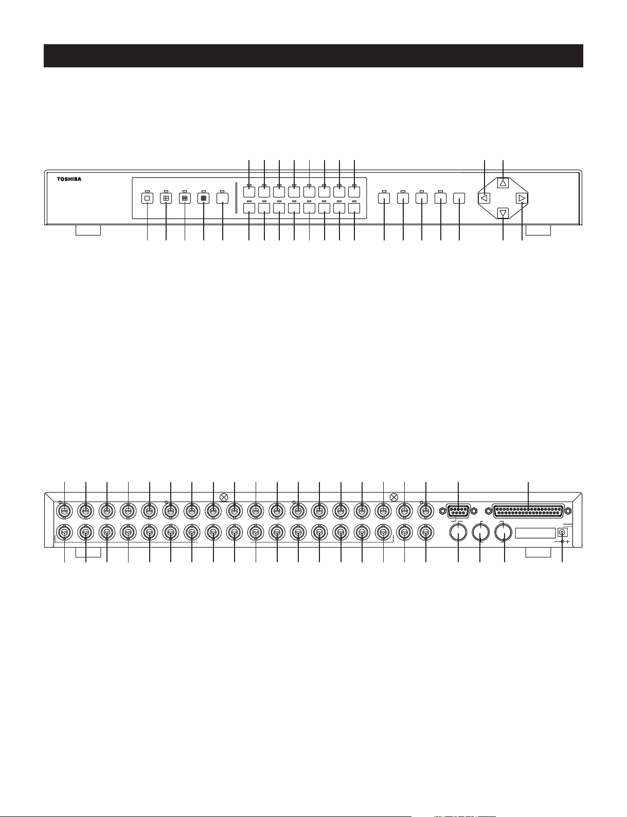
Front Panel
16CH DIGITAL MULTIPLEXER JK-MX16
Rear Panel
MULTI
CAMERA SELECT
192103114125136147158
e
DUPLEX
SEQUENCE ZOOM MENU
VIEW
ALARM
16
RESET
LIVE/
PLAYBACK
ENTER
jk
CALL
LOAD
FREEZE
SAVE
12345 r6t7y8u9ipoq;wasdfgh l/
Digital
H
RECORDER
1 2 3 4 5 6 7 8 9 10 11 12 13 14 15 16 MAIN COM MAIN
CAMERAS/LOOPING
RECORDER IN
CALL
RECORDER OUT
ALARMS/TRIGGER
12345678
OUTIN
DC 5V
()
&z*x(cPvQbWnEmR,T=Y)U!I@O#:$A%S^JDKFLG? Z X
- 7 -
Page 9

Front Panel
FULL SCREEN button
1
Press to set a full screen display.
2x2 button
2
Press to set a 2x2 screen display.
3x3 button
3
Press to set a 3x3 screen display.
4x4 button
4
Press to set a 2x2 screen display.
MULTI button
5
Press to set the following types of displays: Squish screen, Vertical split screen with pan, Squash screen,
Horizontal split screen with pan, 8+2 screen, 12+1 screen, and PIP screen.
6~a
s
d
f
g
CAMERA SELECT buttons 1 through 16
Press to select which camera is to be used for display purpose during Live or Playback mode.
SEQUENCE/ALARM RESET button
This button has multiple functions
• Press to place the cameras into sequence mode
• Press to reset alarm after an activation
• Press to make playback adjustments while in playback mode
• Also used during menu programming
DUPLEX VIEW button
Press to display the camera image and the VCR playback image simultaneously.
ZOOM button
This button has multiple functions
• Press while in live mode to zoom image
• Press to alternate image while in Squish, Squash, Split screen.
LIVE/PLAYBACK/ENTER button
This button has multiple functions
• Press to switch the Live mode and the Playback mode
• Press and hold down to directly view the input image of the VCR
• Also used during menu programming
MENU button
h
Use in conjunction with on screen menus.
- 8 -
Page 10

button
j
This button has multiple functions
• Used during menu programming.
• Used to navigate while in zoom mode.
• Press together with the button to enter the CALL monitor operation mode.
• Press together with the button to permit reloading of the most recently saved front panel display mode.
• Used when making playback adjustments in the playback mode.
• Used to finish setting Day/Night gain level.
button
k
This button has multiple functions
• Used during menu programming.
• Used to navigate while in zoom mode.
• Press together with the button to freeze image.
• Used when setting Day/Night gain level.
button
l
This button has multiple functions
• Used during menu programming.
• Used to navigate while in zoom mode.
• Press together with the button to save the current front panel display mode.
• Used when setting Day/Night gain level.
button
/
This button has multiple functions
• Used during menu programming.
• Used to navigate while in zoom mode.
• Used when making playback adjustments in the playback mode.
• Used when setting Day/Night gain level.
- 9 -
Page 11

Rear Panel
z~S
D
F
G
H
J
CAMERA/LOOPING 1 to 16
These BNC connectors are used to connect the cameras and each has a looping output. The factory setting of
each 75 ohm termination is ON. Two DIP switches inside the unit determine whether the termination is ON or OFF
for each camera input.
MAIN
Main monitor output connector (BNC); connect it to the main monitor.
RECORDER IN
Recorder input connector (BNC); connect it to the video output of the VCR etc.
COM
Use this to connect a personal computer for controlling the multiplexer.
ALARMS/TRIGGER
This connector is used for all alarm inputs, outputs, and also contains the input (REC Trigger In) for synchronizing
VCR to multiplexer. If using a Toshiba time-lapse recorder, a synchronization cable is not required
CALL
This is the call monitor output (BNC) connector. This output is limited to display live full screen images.
RECORDER OUT
K
Recorder output connector (BNC); connect it to the video input of VCR etc.
MAIN
L
Main monitor output connector (S-video connector); connect it to the main monitor.
RECORDER IN
?
Recorder input connector (S-video connector); connect it to the S-video output of the VCR etc.
RECORDER OUT
Z
Recorder output connector (S-video connector); connect it to the S-video input of the VCR etc.
5 V DC
X
Accept the power plug of AC adapter.
- 10 -
Page 12
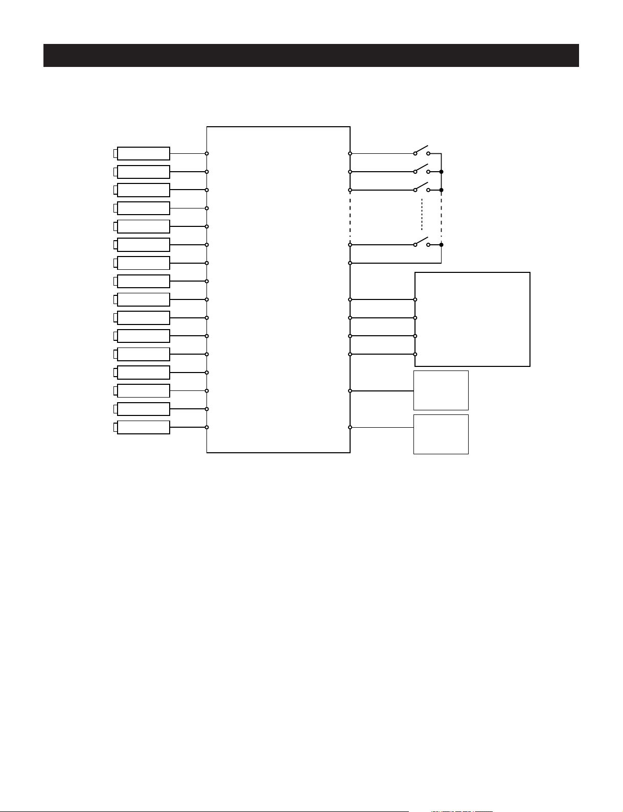
Connection
Basic Wiring Example:
Camera
Camera
Camera
Camera
Camera
Camera
Camera
Camera
Camera
Camera
Camera
Camera
Camera
Camera
Camera
Camera
JX-MX16A
Alarm In
GND
Alarm Out
REC T rigger In
RECORDER OUT
RECORDER IN
MAIN
CALL
VCR
ALARM IN
REC TRIGG. OUT
VIDEO IN
VIDEO OUT
Monitor
Monitor
Installation Steps
(1) If cameras are to be looped out to other devices, the termination switch inside the unit has to be set to off. (Refer
to page 12 for details)
(2) Set the time and date on the menu screen.
(3) If the time-lapse VCR is equipped with an on-screen menu for programming, use the VCR Bypass function to view
the on-screen menu on the monitor. (Refer to page 15 for details).
(4) Select the desired recording mode on the time-lapse recorder.
(5) Select a recording mode in the multiplexer that matches the record mode on the VCR. (Refer to page 22
“Recording Functions” for details
(6) When alarm output contacts of this unit are to be connected to the VCR, it will be necessary to program the alarm
recording duration of the time-lapse recorder to “MANUAL”. The recording duration of the alarm event will be then
be controlled by the dwell time that is programmed in the JK-MX16A. (Refer to page 23 for details).
- 11 -
Page 13
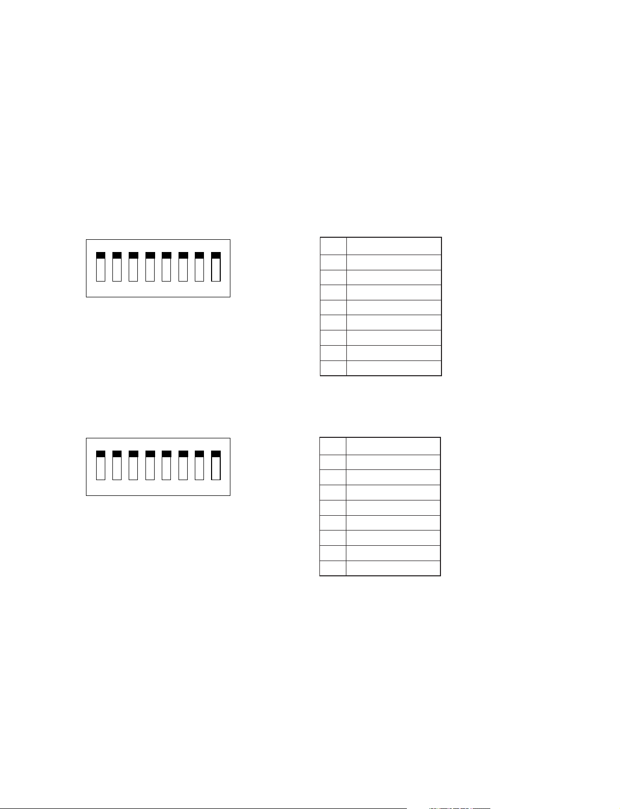
Video Termination Switches (When using the looping connector)
The termination switches are located near the rear panel on the main circuit board. The 75 ohm termination is
enabled when the switch is in the “ON” position. The factory setting of 75 ohm termination for each camera input is
ON. If cameras are to be looped out to other devices, set the termination switch to off.
Setting method
(1) Disconnect the AC adapter. Remove the 8 screws from the side and the 2 screws from rear, then take off the top
cover.
(2) Set the switches (SJ01, SJ02) on the main circuit board to ON or OFF.
(3) Attach the top cover and tighten the screws in their original positions.
(4) Attach the AC adapter.
ON
12345678
SJ01
ON
12345678
SJ02
No. Input Name
1 Camera 1
2 Camera 2
3 Camera 3
4 Camera 4
5 Camera 5
6 Camera 6
7 Camera 7
8 Camera 8
No. Input Name
1 Camera 9
2 Camera 10
3 Camera 11
4 Camera 12
5 Camera 13
6 Camera 14
7 Camera 15
8 Camera 16
- 12 -
Page 14
Operation
Viewing the Camera Image
Use the LIVE/PLAYBACK button to select the Live mode (The LED will light).
Full Screen Display
The camera image can be viewed in a full screen display.
Press the FULL SCREEN button.
1
Press the CAMERA SELECT button of the channel you wish to view. The LED of the selected channel will light
2
at this time.
2x2 Display
The camera image can be viewed in a 2x2 display.
Press the 2x2 button.
1
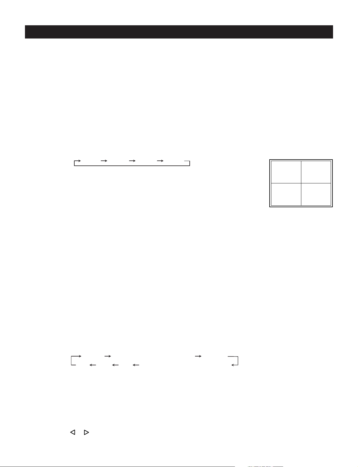
Each time the 2x2 button is pressed, the screen display mode changes as follows:
2x2 A 2x2 B 2x2 C 2x2 D
Display Position
• 2x2 A: Displays Channel 1 to Channel 4.
(The LEDs of CAMERA SELECT buttons 1 to 4 light.)
• 2x2 B: Displays Channel 5 to Channel 8.
(The LEDs of CAMERA SELECT buttons 5 to 8 light.)
• 2x2 C: Displays Channel 9 to Channel 12.
(The LEDs of CAMERA SELECT buttons 9 to 2 light.)
• 2x2 D: Displays Channel 13 to Channel 16.
(The LEDs of CAMERA SELECT buttons 13 to 16 light.)
3x3 Display
The camera image can be viewed in a 3x3 display.
Press the 3x3 button.
1
* The images from the Channel 10 to Channel 16 will not be displayed.
4x4 Display
The camera image can be viewed in a 4x4 display.
Press the 4x4 button.
1
MULTI Display
Camera images can be viewed in a variety of multiple displays.
Press the MULTI button. Each time the MULTI button is pressed, the display mode changes as follows:
1
12
34
- 13 -
Squish Vertical split screen with pan Squash
PIP 12+1 8+2 Horizontal split screen with pan
• Squish
(1)The CAMERA SELECT button can be used to switch the camera image.
(2)The ZOOM button can be used to change the position at which the camera is switched.
• Vertical split screen with pan
(1)The CAMERA SELECT button can be used to switch the camera image.
(2)The ZOOM button can be used to change the position at which the camera image is switched.
(3)The or button can be used to pan the display area.
Page 15

• Squash
(1)The CAMERA SELECT button can be used to switch the camera image.
(2)The ZOOM button can be used to change the position at which the camera is switched.
• Horizontal split screen with pan
(1)The CAMERA SELECT button can be used to switch the camera image.
(2)The ZOOM button can be used to change the position at which the camera image is switched.
(3)The or button can be used to pan the display area.
• 8 + 2
(1)The CAMERA SELECT button can be used to switch the camera image at the upper left of the screen.
(2)The camera image at the upper right of the screen can be changed with menu settings.
• 12 + 1
(1)The CAMERA SELECT button can be used to switch the camera image at the center of the screen.
• PIP
(1)The CAMERA SELECT button can be used to switch the camera image.
(2)The ZOOM button can be used to change the position at which the camera image is switched.
(3)The number of sub screens (up to 2) or the screen display position can be set with the menu.
SEQUENCE Display
Camera images can be viewed in a sequential display.
Press the SEQUENCE button. Depending on the displayed screen, operation will be as follows:
1
• For a full screen display : Camera image is switched in the full screen display.
• For a 2x2 display : Camera image at the lower right position of the 2x2 screen is switched.
• For a 3x3 display : Camera image at the lower right position of the 3x3 screen is switched.
• For an 8+2 display : Camera image at the upper left position of the 8+2 screen is switched.
• For a 12+1 display : Camera image at the center position of the 12+1 screen is switched.
ZOOM
In the Live mode, when a full screen display or a 2x2 display is selected, camera images can be viewed with
portions enlarged. For the 2x2 display, the zoom area can also be moved.
For a full screen display
Press the ZOOM button. Each time the ZOOM button is pressed, the magnification factor changes as follows:
1
2x 3x 4x 5x
Press the , , , or buttons to move the zoom area up, down, left, or right.
2
To cancel the ZOOM display, press the CAMERA SELECT button.
3
For a 2x2 display
Press the ZOOM button.
1
Press the CAMERA SELECT button to select the channel image you wish to view with its portion enlarged, the
2
LED will flash and the magnification of channel image will change to 2x. Press the , , , or buttons to
pan the image.
To exit the Zoom mode, press the ZOOM button, (The LED is not lit) and press the CAMERA SELECT button
3
for desired camera to exit. (The LED is not lit).
- 14 -
Page 16

View the VCR Playback Image
The various display options are as follows:
When playing back a tape that was recorded with the multiplexer set to “Normal” record mode, the following
1
display options are available:
• Full Screen
• 2x2 Screen
• 3x3 Screen
• 4x4 Screen
• 8+2 Screen
• PIP
When playing back a tape that was recorded with the multiplexer set to “High Density” record mode, the
2
following display options are available:
• Full Screen
• 2x2 Screen
VCR Bypass Function
The image output from the VCR can be viewed directly on the main monitor.
Holding down the LIVE/PLAYBACK button for 2 seconds or longer sets the VCR Bypass mode. (The LED is
1
flashing).
To exit the VCR direct mode, press the LIVE/PLAYBACK button one more time.
2
VCR Playback Adjustment Function
The JK-MX16A has the VCR Playback Adjustment function for offering users improved image quality and
synchronization.
• Adjustment
(1) Use the LIVE/PLAYBACK button to select the playback mode (and LED will go off).
(2) Play the time-lapse VCR.
(3) Press the SEQUENCE button.
(4) The VCR playback adjustment screen will appear.
(5) Press the or button to minimize the mixing of the images of other channels.
(6) Press the SEQUENCE button once again to return to the original screen.
* Please readjust this adjustment when the playback speed of the time-lapse VCR has been changed.
* Please readjust this adjustment when playing back a tape that has been recorded in a different recording time
mode.
* These adjustment contents will return to normal when the power is off.
- 15 -
Page 17

Using the DUPLEX VIEW Function to Simultaneously View Live Camera Images and VCR Playback
Images.
(1) To view the VCR playback image while viewing the live camera image...
Press the LIVE/PLAYBACK button and select the Live mode. (The LED will light).
1
Press the DUPLEX VIEW button. The LED will light and the Window screen will display.
2
Press the CAMERA SELECT button to display the desired camera image from the VCR playback images.
3
To exit the Duplex view mode, press the DUPLEX VIEW button. (The LED is not lit).
4
(2) To view the camera image while viewing the VCR playback image...
Press the LIVE/PLAYBACK button and select the Playback mode. (The LED is not lit).
1
Press the DUPLEX VIEW button. The LED will light and the Window screen will display.
2
Press the CAMERA SELECT button to display the desired camera image.
3
To exit the Duplex view mode, press the DUPLEX VIEW button. (The LED is not lit).
4
(3) Display position of the Duplex View Window
The display position of the window will be different for full screen, 2x2 screen, 8+2 screen, and 12+1 screen.
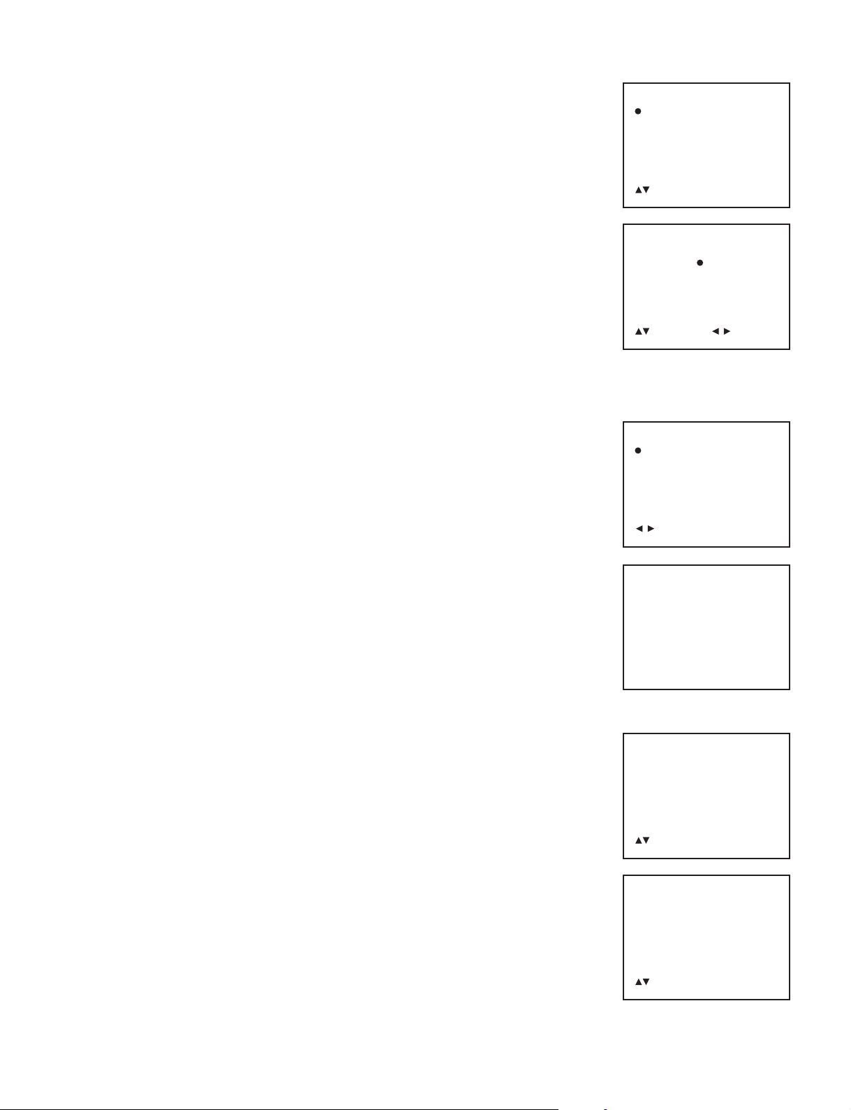
• Full screen
During a full screen display, the Duplex View Window is brought out among
positions one to four according to the position set in the menu.
• 2x2 screen
The display position will be positioned at 4.
Monitor Screen
12
34
Monitor Screen
4
- 16 -
Page 18

• 8+2 screen
The Duplex View Window will be in position A.
* When a recording is made and the multiplexer is programmed in “High
Density” mode, the 8+2 screen is not available.
Monitor Screen
A
• 12+1 screen
The Duplex View Window will be in position A.
* This screen pattern is only displayed in the Live mode.
Monitor Screen
A
Day/Night Function
This unit is a time-linked function that provides increased gain of the video level of the various cameras. To further
improve the S/N ratio of the image, the signal is intentionally output as a black-and-white signal.
The Day/Night function will function on the main monitor output as well as the VCR output; however, it will not
function on the call monitor output.
Note that if the Night mode is set while normal level video is being input, such as a daytime scene, the output
image will exhibit a white-out phenomenon. Please exercise caution when setting this function.
- 17 -
To set the Day/Night Function gain, use the , , , or buttons in the Full screen.
(1) Use the LIVE/PLAYBACK button to select the Live mode. (The LED will light).
(2) Press the FULL SCREEN button to display the Full screen.
(3) Select the camera to set and press the button.
(4) Press the or button to set the gain you desired.
Gain
L:Low
1
M : Medium
2
H : High
3
(5) Press the button to finish setting Day/Night gain level.
Page 19

SET UP
Menu
System Set-up
Camera Functions
Recording Set-up
Alarm Functions
Multi-view Functions
Sequence Set-up
Security Set-up
:Select :Next
MENU:Exit
The JK-MX16A Set Up is accomplished through its on-screen menus. To enter the menu system, press the MENU
button. The display will then show the main menu. Selection from the various items of the menu is done with the , ,
, , ENTER, and MENU buttons. Press the MENU button to exit from the main menu.
Main Menu
The main menu contains the following 7 sub menus.
System Set-up
This sets the date display function,
serial communication parameters, etc.
Camera Functions
This sets the title display, Day/night functions, etc.
Recording Set-up
This sets the functions that are recorded to the VCR.
Alarm Functions
This set the alarm functions.
Multi-view Functions
This set the Multi-view functions.
Sequence Set-up
This sets the automatic switching functions.
Security Set-up
This sets the security functions.
- 18 -
Page 20

Setting Contents
1. System Set-up
1.1 Time & Date Functions
Hour Format
Sets the hour display format.
24H : 24-hour display
1
AM/PM : 12-hour display
2
Date Format
Sets the date display format.
MMMM/dd/yy : e.g., Oct./01/2000 (Month/Day/Year)
1
yy/MMMM/dd : e.g., 2000/Oct./01 (Year/Month/Day)
2
dd/MMMM/yy : e.g., 01/Oct./2000 (Day/Month/Year)
3
yy/MM/dd : e.g., 2000/10/01 (Year/Month/Day)
4
MM/dd/yy : e.g., 10/01/2000 (Month/Day/Year)
5
dd/MM/yy : e.g., 01/10/2000 (Day/Month/Year)
6
MM/dd/dddd/yy : e.g., 10/01/SUN./2000 (Month/Day/Day of the week/Year)
7
Time & Date Set-up
Sets the time and date. The current time can be entered in increments of one minute. Pressing the ENTER button
will reset the second counter to zero.
System Set-up
Time & Date Functions
Font Color
Comm. Set-up
Save/Recall
Default
:Select ENTER:Next
MENU:Return
Time & Date Functions
Hour Format
Date Format
Time & Date Set-up
Daylight Savings
T&D View Main Mon
T&D View Call Mon
T&D View VCR PB
Time & Date Position
:Select ENTER:Next
MENU:Return
Daylight Savings
Sets Daylight Saving Time on and off.
Select On (from the Off condition) and press the MENU button to advance the time by 1 hour. Select Off (from the
On condition) and press the MENU button to turn back the time by 1 hour.
T&D View Main Mon
Sets the time and date display of the main monitor screen On/Off.
On : Displays the date and time on the main monitor.
1
Off : Does not display the date and time on the main monitor.
2
T&D View Call Mon
Sets the time and date display of the call monitor screen On/Off.
On : Displays the date and time on the call monitor.
1
Off : Does not display the date and time on the call monitor.
2
T&D View VCR PB
Sets the time and date display of the VCR playback screen On/Off.
On : Displays the date and time on the VCR playback screen.
1
Off : Does not display the date and time on the VCR playback screen.
2
Time & Date Position
Sets the position at which the time and date are displayed. When the line is the same as the title position, the title
has priority and the time and date are not displayed. This is the same for each of the main monitor output (i.e.,
camera live screen and VCR playback screen) and the call monitor output.
Top : Displayed at the top of the screen.
1
Bottom : Displayed at the bottom of the screen.
2
- 19 -
Page 21
1.2 Font Color
The color of the characters on main monitor screen can be changed.
White 2 Yellow 3 Cyan 4 Green 5 Magenta 6 Red 7 Blue
1
1.3 Comm. Set-up
Sets the serial communications items.
COM speed
Sets the transfer speed.
4800 : Transfer speed of 4800 bps
1
9600 : Transfer speed of 9600 bps
2
19200: Transfer speed of 19200 bps
3
COM address
Sets the communications address.
1.4 Save/Recall
The contents of the menu screen can be saved and recalled.
Save : Saves the setting contents of the current menu screen. (After the Save is
1
executed, it will take approx. 1 minute to complete it.)
Recall: Recalls the setting contents of the previously saved menu screen. (After
2
the Recall is executed, it will take approx. 1 minute to complete it.)
1.5 Default
A press of the ENTER button on this screen permits all of the menu screen setting
contents (with the exception of the clock) to be returned to the default values that
were in effect at time of shipping. (After the Default is executed, it will take approx. 1
minute 30 seconds to complete it.)
Font Color
White
Yellow
Cyan
Green
Magenta
Red
Blue
:Set-up
MENU:Accept & Return
Comm. Set-up
COM speed:
4800 9600 19200
COM address: 1 [1-31]
:Select :Set-up
MENU:Accept & Return
Save/Recall
Save Recall
:Set-up
ENTER:Execute MENU:Return
Default
Default Yes?
2. Camera Functions
2.1 Title Functions
Camera Title
Inputs the title (character display) of each channel. Entry of a maximum of 10
characters (alphanumeric and symbols) is permitted for each channel.
Note: for screens of 1/9 size and 1/16 size, only the camera number can be
accommodated.
Title View Main Mon
Sets the title display of the main monitor screen On/Off. Settings can be made for
each channel, independently.
Off : Does not display the title on the main monitor screen.
1
On : Displays the title on the main monitor screen.
2
Title View Call Mon
Sets the title display of the call monitor screen On/Off. Settings can be made for
each channel, independently.
Off : Does not display the title on the call monitor screen.
1
On : Displays the title on the call monitor screen.
2
ENTER:Execute MENU:Return
Camera Functions
Title Functions
Discreet Cam Set-up
Day/Night Set-up
:Select ENTER:Next
MENU:Return
Title Functions
Camera Title
Title View Main Mon
Title View Call Mon
Title View VCR PB
Title Position
Channel View Main Mon
:Select ENTER:Next
MENU:Return
- 20 -
Page 22

Title View VCR PB
Sets the title display of the VCR playback screen On/Off. Settings can be made for each channel, independently.
Off : Does not display the title on the VCR playback screen.
1
On : Displays the title on the VCR playback screen.
2
Title Position
Sets the position at which the title of the camera live screen (i.e., main monitor output) will be displayed (Full
screen display only). The title display position is fixed for the call monitor screen.
Top : Displayed at the top of the screen.
1
Bottom : Displayed at the bottom of the screen.
2
Channel View Main Mon
Sets the camera number display of the 1/9 size and 1/16 size screens On/Off.
Off : Does not display the camera number.
1
On : Displays the camera number.
2
2.2 Discreet Cam Set-up
Sets the screen mute On/Off. Settings can be made for each channel, independently.
Off : Displays the image.
1
On : Does not display the image.
2
Discreet Cam Set-up 1/2
CH1: Off On
CH2: Off On
CH3: Off On
CH4: Off On
CH5: Off On
CH6: Off On
CH7: Off On
CH8: Off On
:Select :Set-up
MENU:Accept & Return
2.3 Day/Night Set-up
Sets the Day/Night function On/Off. Settings can be made for each channel,
independently.
Off : Does not use the Day/Night function.
1
On : Uses the Day/Night function.
2
Sche. : When within the set time, the Day/Night function will be activated.
3
3. Recording Set-up
3.1 Camera Rec Select
Sets the channel that is recorded on the VCR. Settings can be made for each
channel, independently.
Off : Does not record to VCR.
1
On : Records to VCR.
2
Sche. : Records to VCR when the time is within the set time.
3
Day/Night Set-up 1/2
CH1: Off On
CH2: Off On
CH3: Off On
CH4: Off On
CH5: Off On
CH6: Off On
CH7: Off On
CH8: Off On
:Select :Set-up
MENU:Accept & Return
Recording Set-up
Camera Rec Select
Recording Functions
VCR Input Select
Camera Priority Rec
High density Mode
:Select ENTER:Next
MENU:Return
Camera Rec Select 1/2
CH1: Off On Sche.
CH2: Off On Sche.
CH3: Off On Sche.
CH4: Off On Sche.
CH5: Off On Sche.
CH6: Off On Sche.
CH7: Off On Sche.
CH8: Off On Sche.
:Select
MENU:Return ENTER:Auto
:Set-up
- 21 -
Page 23

3.2 Recording Function
Sets the VCR recording mode and time mode.
Normal mode:
SP : SP mode (Example, 2 hour & 12 hour modes are SP modes).
1
EP : EP mode (Example 6 hour, 18 hour mode, & 24 Hour Virtual Real-time
2
modes are EP modes). Note: LP: LP mode applies when unit is switch to
PAL mode. (Refer to page 34 for “Changing the Internal Switch”)
Recording Function
Normal mode: SP EP
Alarm mode: SP EP
:Select :Set-up
MENU:Accept & Return
Normal time: Sets the VCR recording time mode
When the SP mode has been selected with the aforementioned mode selection,
2H (3H in the PAL version) 2 12H 3 24H 4 36H 5 48H 6 72H 7 96H 8 120H 9 168H
1
240H q 360H
p
480H e 720H r 960H
w
When the EP (LP in the PAL version) mode has been selected with the aforementioned mode selection,
6H 2 18H 3 24H 4 30H 5 48H 6 72H 7 96H 8 120H 9 168H p 240H q 360H
1
480H e 720H r 960H
w
Alarm mode:
SP : SP mode
1
EP : EP mode (LP : LP mode in the PAL version)
2
time: 6H 18H 24H
30H 48H 72H 96H
120H 168H 240H 360H
480H 720H 960H
time: 2H 12H 24H
Alarm time: Sets the VCR recording time mode .
When the SP mode has been selected with the aforementioned mode selection,
2H (3H in the PAL version) 2 12H 3 24H
1
When the EP (LP in the PAL version) mode has been selected with the aforementioned mode selection,
6H 2 18H 3 24H
1
3.3 VCR Input Select
Sets the VCR input connectors.
BNC : BNC connector (When a composite signal is input)
1
S-VIDEO: S-VIDEO connector (When an S-video signal is input)
2
VCR Input Select
BNC S-VIDEO
:Set-up
MENU:Accept & Return
3.4 Camera Priority Rec
When there are 3 or more camera inputs, the channel that is recorded to the VCR
can be given priority. Settings can be made for each channel, independently.
L : Sets the priority lower.
1
H : Sets the priority higher.
2
Al : Optimizes the priority depending on the alarm information that has
3
already been input.
Sche. : Sets the priority higher when the time is within the set time.
4
Camera Priority Rec 1/2
CH1: L H AI Sche.
CH2: L H AI Sche.
CH3: L H AI Sche.
CH4: L H AI Sche.
CH5: L H AI Sche.
CH6: L H AI Sche.
CH7: L H AI Sche.
CH8: L H AI Sche.
:Select :Set-up
MENU:Accept & Return
- 22 -
Page 24

3.5 High density Mode
Sets the multiplexer into high-density mode. When high-density mode is selected,
the multiplexer compresses two fields of information into one field thereby doubling
the refresh rate. While the refresh rate is improved when high-density mode is
enabled, there is a slight loss in image quality caused by image compression.
Normal : Standard (normal) density mode
1
High density : High-density mode
2
Note: If the multiplexer is not set to 24 Hour or longer (SP) or 48 Hour or longer
(EP) in the Recording function menu, you can not set the High density
mode on it.
We recommend the multiplexer is used with the VCR time and date display
set to off.
4. Alarm Functions
4.1 Alarm Rec Priority
When an alarm signal is activated, camera priority recording can be programmed
from this menu.
Level 3:Only the camera that has an active alarm is recorded. All other cameras
1
are ignored for the duration of the alarm condition.
2
Level 2:
The alarmed camera is recorded at a higher priority than non-alarmed
cameras (example: In a 4 camera system, when camera #4 is alarmed the
camera sequence would be as follows: 4,4,4,4,4,1,4,4,4,4,4,2,4,4,4,4,4,3).
Level 1:The alarmed camera is recorded at a higher priority than non-alarmed
3
cameras (example: In a 4 camera system, when camera #4 is alarmed
the camera sequence would be as follows: 4,4,4,1,4,4,4,2,4,4,4,3).
Level 0:No change to the recording sequence when an alarm is activated.
4
High density Mode
Normal High density
:Set-up
MENU:Accept & Return
Alarm Functions
Alarm Rec Priority
Alarm Input
Motion Functions
Video loss
Alarm Event Log
:Select ENTER:Next
MENU:Return
Alarm Rec Priority
Level: [ 3 ]
[High >>>> Low]
4.2 Alarm Input
Alarm Type
Sets the type of alarm input signal.
N.C : Normal Closed. When the contact is open, alarm will be set to operation.
1
N.O : Normal Open. When the contact is closed, alarm will be set to operation.
2
L.L : Logic Low. Alarm input in the logic “Low” level will sets the alarm operation.
3
L.H : Logic High. Alarm input in the logic “High” level will sets the alarm operation.
4
Main Mon Callout
When an alarm signal is activated, the main monitor displays the alarmed camera
channel. Each camera channel can be programmed independently.
Off : Alarmed camera is not called out to main monitor.
1
On : Alarmed camera is called out to main monitor.
2
Sche. : Alarmed camera is called out to main monitor based on a timer schedule.
3
Main Mon Display
Sets the display screen of the main monitor output when the alarm signal has been input.
Full : Full screen
1
2x2 : 2x2 screen
2
3x3 : 3x3 screen
3
4x4 : 4x4 screen
4
:Set-up
MENU:Accept & Return
Alarm Input
Alarm Type
Main Mon Callout
Main Mon Display
Call Mon Callout
VCR Callout
Alarm Dwell time
Buzzer
:Select ENTER:Next
MENU:Return
- 23 -
Page 25

Call Mon Callout
When an alarm signal is activated, the call monitor output displays the alarmed camera channel. Each camera
channel can be programmed independently.
1 Off : Does not callout alarmed camera to call monitor when alarm signal is activated.
2 On : Calls out alarmed camera to call monitor when alarm signal is activated.
3 Sche. : Calls out alarmed camera to call monitor based on a timer schedule.
VCR Callout
When an alarm signal is activated, the VCR records the camer a that is in alarm condition with higher priority.
Recording priority is set in the Alarm Rec. Priority menu.
Off : Alarmed camera is not routed to the VCR for priority recording.
1
On : Alarmed camera is routed to the VCR for priority recording.
2
Sche. : Alarmed camera is routed to the VCR for priority recording based on timer schedule.
3
Alarm Dwell Time
Sets the alarm dwell time when the alarm signal has been input. Settings can be made for each channel,
independently.
10 sec ... 180 sec Manual Inf 01 sec ...
1 to 180 sec
1
Manual : Alarm operation is held while the alarm signal is being input.
2
Inf :
3
: Alarm operation is held only for the set time.
The alarm operation is held until the ALARM RESET reset button is pressed or the power is s witched off.
Buzzer
Sets the buzzer On/Off when the alarm signal is input. Settings can be made for each channel, independently.
Off : Buzzer is not sounded.
1
On : Buzzer is sounded.
2
4.3 Motion Functions
Motion Sensitivity
Sets the sensitivity of the motion detection. Settings can be made for each channel,
independently.
Low : Low sensitivity
1
Middle: Normal
2
High : High sensitivity
3
Motion Functions 1/2
Motion Sensitivity
Motion Direction
Motion Size
Motion Area
Detection Mode
Motion Counter Display
:Select ENTER:Next
MENU:Return
Motion Direction
Sets the detection direction of the motion detection. Settings can be made for each channel, independently.
Overall Top Bottom Bottom Top Right Left
Right & Left
Overall : All up/down and left/right directions
1
Top Bottom : From top to bottom direction only
2
Bottom Top : From bottom to top direction only
3
Right Left : From right to left direction only
4
Left Right : From left to right direction only
5
Top & Bottom : Vertical direction (from top to bottom, or from bottom to top) only
6
Right & Left : Horizontal direction (from right to left, or left to right) only
7
Top & Bottom Right Left
- 24 -
Page 26

Motion Size
Sets the size of the cell that detects the motion. Settings can be made for each channel, independently.
S : Small cell size
1
M : Medium cell size
2
L : Large cell size
3
Motion Area
Sets the detection area of the motion detection. Settings can be made for each channel, independently.
Manual : Cursor is used to set the detection range.
1
Auto : Sets the range in which motion occurred within a fixed time to an insensitive zone.
2
Detection Mode
Sets whether the motion detection will be used as an alarm or as a counter.
Alarm : Used as an alarm
1
Counter: Used as a counter
2
Motion Counter Display
The number of times motion has been detected sets the main monitor On/Off (Full screen display only). Settings
can be made for each channel, independently.
Off : Not displayed. (Displayed only on the menu screen.)
1
On : Displayed
2
Main Mon Callout
When the motion detection is programmed to act as an alarm, the main monitor can
be programmed to display the motion alarmed camera. Each camera can be
programmed independently..
Off : Motion alarmed camera is not called out to main monitor.
1
On : Motion alarmed camera is called out to main monitor.
2
Sche. : Motion alarmed camera is called out to main monitor based on a timer
3
schedule.
Motion Functions 2/2
Main Mon Callout
Main Mon Display
Call Mon Callout
VCR Callout
Motion Dwell time
Buzzer
:Select ENTER:Next
MENU:Return
Main Mon Display
Sets the display screen of the main monitor output when the motion detection is used as an alarm.
Full : Full screen
1
2x2 : 2x2 screen
2
3x3 : 3x3 screen
3
4x4 : 4x4 screen
4
Call Mon Callout
When the motion detection is programmed to act as an alarm, the call monitor displays the motion alarmed
camera. Each camera can be programmed independently.
Off : Motion alarmed camera is not called out to call monitor.
1
On : Motion alarmed camera is called out to call monitor.
2
Sche. : Motion alarmed camera is called out to call monitor based on a timer schedule.
3
- 25 -
VCR Callout
When the motion detection is programmed to act as an alarm, the VCR records the camera that is in alarm
condition with higher priority. Recording priority is set in the Alarm Rec. Priority menu.
Off : Motion alarmed camera is not routed to the VCR for priority recording.
1
On : Motion alarmed camera is routed to the VCR for priority recording.
2
Sche. : Motion alarmed camera is routed to the VCR for priority recording based on timer schedule.
3
Page 27

Motion Dwell Time
Sets the alarm dwell time when the motion detection is used as an alarm. Settings can be made for each channel,
independently.
10 sec ... 180 sec Inf 01 sec ...
1 to 180 sec
1
Inf : Press the ALARM RESET button or maintain the alarm operation until the power is switched off.
2
: Holds the alarm operation for the set time only.
Buzzer
Sets the buzzer On/Off when the motion detection is used as an alarm.
Off : Buzzer is not sounded.
1
On : Buzzer is sounded.
2
4.4 Video Loss
Video Loss on/off
Sets the channel to perform video loss detection. Settings can be made for each
channel, independently.
Off : Video loss is not detected.
1
On : Video loss is detected
2
Sche. : Detects video loss when the time is within the set time.
3
Video Loss
Video Loss on/off
Main Mon Callout
Video Loss Dwell Time
Buzzer
:Select ENTER:Next
MENU:Return
Main Mon Callout
Sets the operation of the main monitor output when video loss has been detected. Settings can be made for each
channel, independently.
Off : No action is taken even if video loss is detected.
1
On : The screen takes on the 4x4 screen format when video loss is detected and “LOSS” is displayed.
2
(Video loss operation)
Video Loss Dwell Time
Sets the video loss dwell time when video loss has been detected. Settings can be made for each channel,
independently.
10 sec ... 180 sec Inf 01 sec ...
1 to 180 sec
1
Inf :
2
Buzzer
Sets the buzzer On/Off when video loss has been detected.
Off : Buzzer is not sounded.
1
On : Buzzer is sounded.
2
4.5 Alarm Event Log
Allows view of all activity log event including video loss, motion detection activation,
and alarm input activation.
: Holds the alarm operation for the set time only.
Press the ALARM RESET button or maintain the video loss operation until the pow er is switched off.
Alarm Event Log
[No.] [CH] [Date] [Time] [A]
0 --
:Next MENU:Return
SEQUENCE:Reset
- 26 -
Page 28

5. Multi-view Functions
5.1 PIP #1
Sets the display position of sub screen 1 for picture-in-picture (PIP) display. There
will not be a PIP display when “None” has been selected.
T op-Left
1
T op-Right
2
Bottom-Left
3
Bottom-Right
4
None
5
5.2 PIP #2
Sets the display position of sub screen 2 for picture-in-picture (PIP) display. There
will not be a PIP display when “None” has been selected.
T op-Left
1
T op-Right
2
Bottom-Left
3
Bottom-Right
4
None
5
Multi-view Functions
PIP #1
PIP #2
8+2 Fix Cam Select
Duplex position
:Select ENTER:Next
MENU:Return
PIP #1
Top-Left
Top-Right
Bottom-Left
Bottom-Right (PIP #2)
None
:Set-up
MENU:Accept & Return
PIP #2
Top-Left (PIP #1)
Top-Right
Bottom-Left
Bottom-Right
None
:Set-up
MENU:Accept & Return
5.3 8+2 Fix Cam Select
Sets the spot channel of the 8+2 screen.
5.4 Duplex position
Sets the display position of the sub screen in the duplex view mode.
T op-Left
1
T op-Right
2
Bottom-Left
3
Bottom-Right
4
8+2 Fix Cam Select
Ch1 [Ch1-Ch16]
:Set-up
MENU:Accept & Return
Duplex position
Top-Left
Top-Right
Bottom-Left
Bottom-Right
:Set-up
MENU:Accept & Return
- 27 -
Page 29

6. Sequence Set-up
6.1 Call Mon Sequence
The camera sequence dwell time and camera selection that's displayed in the call
monitor can be programmed in this menu. By pressing the ENTER button while in the
Call Mon Sequence menu, all connected cameras will be added to the call monitor
sequence selection. Once the ENTER button is pressed, the multiplexer will detect the
presence of a camera input signal and will automatically add each camera to the
sequence process.
Ch : Each camera can be programmed to sequence in any desired order within
this menu.
Dwell : 1 sec to 60 sec
6.2 Main Mon Sequence
The camera sequence dwell time and camera selection that is displayed in the main
monitor can be programmed in this menu. By pressing the
the Main Mon Sequence menu, all connected cameras will be added to the main
monitor sequence selection. Once the
ENTER
button is pressed, the multiplexer will
detect the presence of a camera input signal and will automatically add each camera
to the sequence process.
Ch : Each camera can be programmed to sequence in any desired order within
this menu.
Dwell : 1 sec to 60 sec.
ENTER
button while in
Sequence Set-up
Call Mon Sequence
Main Mon Sequence
2x2 Sequence
3x3 Sequence
8+2 Sequence
12+1 Sequence
:Select ENTER:Next
MENU:Return
Call Mon Sequence
1:ch1 07:ch7 12:ch12
2:ch2 8:ch8 13:ch13
3:ch3 9:ch9 14:ch14
4:ch4 10:ch10 15:ch15
5:ch5 11:ch11 16:ch16
6:ch6 Dwell: 03sec
ENTER:Auto Set-up
:Select :Set-up
MENU:Accept & Return
Main Mon Sequence
1:ch1 07:ch7 12:ch12
2:ch2 8:ch8 13:ch13
3:ch3 9:ch9 14:ch14
4:ch4 10:ch10 15:ch15
5:ch5 11:ch11 16:ch16
6:ch6 Dwell: 03sec
ENTER:Auto Set-up
:Select :Set-up
MENU:Accept & Return
6.3 2x2 Sequence
The camera sequence dwell time and camera selection that is displayed in the lower
right channel of a 2x2 display can be programmed in this menu. By pressing the
ENTER
button while in the 2x2 Sequence menu, all connected cameras will be
added to the sequence selection of the lower right channel in the 2x2 display. Once
the
ENTER
button is pressed, the multiplexer will detect the presence of a camera
input signal and will automatically add each camera to the sequence process.
Ch : Each camera can be programmed to sequence in any desired order within
this menu.
Dwell : 1 sec to 60 sec.
6.4 3x3 Sequence
The camera sequence dwell time and camera selection that is displayed in the lower
right channel of a 3x3 display can be programmed in this menu. By pressing the
ENTER
button while in the 3x3 Sequence menu, all connected cameras will be
added to the sequence selection of the lower right channel in 3x3 display. Once the
ENTER
button is pressed, the multiplexer will detect the presence of a camera input
signal and will automatically add each camera to the sequence process.
Ch : Each camera can be programmed to sequence in any desired order within
this menu.
Dwell : 1 sec to 60 sec
2x2 Sequence
1:ch1 07:ch7 12:ch12
2:ch2 8:ch8 13:ch13
3:ch3 9:ch9 14:ch14
4:ch4 10:ch10 15:ch15
5:ch5 11:ch11 16:ch16
6:ch6 Dwell: 03sec
ENTER:Auto Set-up
:Select :Set-up
MENU:Accept & Return
3x3 Sequence
1:ch1 07:ch7 12:ch12
2:ch2 8:ch8 13:ch13
3:ch3 9:ch9 14:ch14
4:ch4 10:ch10 15:ch15
5:ch5 11:ch11 16:ch16
6:ch6 Dwell: 03sec
ENTER:Auto Set-up
:Select :Set-up
MENU:Accept & Return
- 28 -
Page 30

6.5 8+2 Sequence
The camera sequence dwell time and camera selection that is displayed in the
upper left channel of an 8+2 display can be programmed in this menu. By
pressing the
ENTER
button while in the 8+2 Sequence menu, all connected
cameras will be added to the sequence selection of the upper left 8+2 display.
Once the
ENTER
button is pressed, the multiplexer will detect the presence of a
camera input signal and will automatically add each camera to the sequence
process.
Ch : Each camera can be programmed to sequence in any desired order within
this menu.
Dwell : 1 sec to 60 sec
6.6 12+1 Sequence
The camera sequence dwell time and camera selection that is displayed in the
center channel of a 12+1 display can be programmed in this menu. By pressing
the
ENTER
button while in the 12+1 Sequence menu, all connected cameras will
be added to the sequence selection of the center channel 12+1. Once the
button is pressed, the multiplexer will detect the presence of a camera input signal
and will automatically add each camera to the sequence process.
Ch : Each camera can be programmed to sequence in any desired order within
this menu
Dwell : 1 sec to 60 sec
ENTER
8+2 Sequence
1:ch1 07:ch7 12:ch12
2:ch2 8:ch8 13:ch13
3:ch3 9:ch9 14:ch14
4:ch4 10:ch10 15:ch15
5:ch5 11:ch11 16:ch16
6:ch6 Dwell: 03sec
ENTER:Auto Set-up
:Select :Set-up
MENU:Accept & Return
12+1 Sequence
1:ch1 07:ch7 12:ch12
2:ch2 8:ch8 13:ch13
3:ch3 9:ch9 14:ch14
4:ch4 10:ch10 15:ch15
5:ch5 11:ch11 16:ch16
6:ch6 Dwell: 03sec
ENTER:Auto Set-up
:Select :Set-up
MENU:Accept & Return
7. Security Set-up
Menu Lock
Sets security lock On/Off for the menu operation. When setting to On, the security
code (access code) will be required to operate the menu.
Off : Does not lock the menu operation.
1
On : Locks the menu operation.
2
To set the access code:
From the main menu, select the “Security Set-Up” in order to enter the security
menu.
By pressing the Button while the cursor is on the “menu Lock”, the access code
field will be displayed.
Access Code: ....
At this point, enter a four digit password by using the CAMERA SELECT buttons 1
through 10. The message “Re-enter to confirm” will appear. Re-enter password to
confirm.
Button Lock
Sets security lock On/Off for the button operation of the Front panel. When setting
to On, you can not operate the Front panel.
Off : Does not lock the button operation.
1
On : Locks the button operation.
2
Security Set-up
Menu Lock: Off
Button Lock: Off
Remote Lock: Off
:Select :Set-up
MENU:Accept & Return
Security Set-up
Menu Lock: On
Button Lock: Off
Remote Lock: Off
Access Code: . . . .
Camera:1~9,10(0)
- 29 -
Remote Lock
Sets security lock On/Off for the remote control operation. When setting to On, you
can not operate the remote control.
Off : Does not lock the
1
On : Locks the
2
remote control operation
remote control operation
.
.
Page 31

Schedule setting
The schedule management function serves to operate the Day/Night or alarm operations daily for only a specific time
over a period of one week.
Setting of the schedule is done on the schedule setting screen by setting the starting time and ending time.
Setting Method
(1) Press the or button on the schedule setting screen and select the day.
(2) Press the button and select starting time.
(3) Press the or button, set the starting hours, and press the button.
(4) Press the or button, set the starting minutes, and press the button.
(5) Press the or button, set the ending hours, and press the button.
(6) Press the or button, set the ending minutes, and press the button.
(7) Press the MENU button to complete the schedule settings.
***************** Schedule
[ch*] ON OFF [24H]
Sun : 12:00 ~ 18:00
Mon: 12:00 ~ 18:00
Tue : 12:00 ~ 18:00
Wed: 12:00 ~ 18:00
Thu : 12:00 ~ 18:00
Fri : 12:00 ~ 18:00
Sat : 12:00 ~ 18:00
:Week :Time
MENU:Accept & Return
Motion Area Setting
You can set the motion detection range in the Motion Area setting menu. There
are two methods available, Manual and Auto.
Manual
(1) Use the or button to select “Manual”.
(2) A press of the button will display the range over which motion detection is
enabled. Portions indicated by a “o” make up the enabled range.
(3) When there is a portion for which motion detection is not desired, move the cursor
with the , , or buttons, then press the ENTER button (and the “o” marks
will disappear).
(4) Press the MENU button to set the range.
Auto
(1) Use the or button to select “Auto”.
(2) A press of the button will display the screen that indicates the range over which
motion detection is disabled. In this condition, the portions for which motion was
detected will automatically become the disabled range (and an “x” mark will be
displayed).
(3) Press the MENU button to set the range.
Motion Area 1/2
CH1: Manual Auto
CH2: Manual Auto
CH3: Manual Auto
CH4: Manual Auto
CH5: Manual Auto
CH6: Manual Auto
CH7: Manual Auto
CH8: Manual Auto
:Set-up :Set-up
MENU:Accept & Return
* Should the motion detection respond in an oversensitive manner, lower the sensitivity and set the size larger.
- 30 -
Page 32

Factory Default Settings
The factory default settings of menu are as indicated below. When the default settings are set, all items except for the
time input are set to the condition of the factory default settings.
Item
1. System Set-up
1.1 Time & Date Functions
Hour Format
Date Format
Time & Date set up
Daylight Savings
T&D View Main Mon
T&D View Call Mon
T&D View VCR PB
Time & Date Position
1.2 Font Color
1.3 Comm. set-up
COM speed
COM address
1.4 Save / Recall
2. Camera Functions
2.1 Title Functions
Camera Title
Title View Main Mon
Title View Call Mon
Title View VCR PB
Title Position
Channel View Main Mon
2.2 Discreet Cam Set-up
2.3 Day / Night Set-up
3. Recording Set-up
3.1 Camera Rec select
3.2 Recording Function
Normal mode
Normal time
Alarm mode
Alarm time
3.3 VCR Input Select
3.4 Camera Priority Rec
3.5 High density Mode
Factory default setting
24H
MM / dd / yy
10 / 01 / 2000
On
On
On
On
Top
White
9600
1
Save
CAMERA * (*=Channel No.)
On ( All channel )
On ( All channel )
On ( All channel )
Bottom
On ( All channel )
Off ( All channel )
Off ( All channel )
On ( All channel )
EP
18H
SP
2H
BNC
L ( All channel )
Normal
- 31 -
Page 33

Factory Default Settings (continued)
Item
4. Alarm Functions
4.1 Alarm Rec Priority
4.2 Alarm Input
Alarm T ype
Main Mon Callout
Main Mon Display
Call Mon Callout
VCR Callout
Alarm Dwell Time
Buzzer
4.3 Motion Functions
Motion Sensitivity
Motion Direction
Motion size
Motion Area
Detection mode
Motion counter Display
Main Mon Callout
Main Mon Display
Call Mon Callout
VCR Callout
Main Motion Dwell Time
Buzzer
4.4 Video Loss
Video Loss on/off
Main Mon Callout
Video Loss Dwell Time
Buzzer
4.5 Alarm Event Log
5. Multi-view Functions
5.1 PIP #1
5.2 PIP #2
5.3 8+2 Fix Cam Select
5.4 Duplex position
6. Sequence Set-up
6.1 Call Mon Sequence
6.2 Main Mon Sequence
6.3 2x2 Sequence
6.4 3x3 Sequence
6.5 8+2 Sequence
6.6 12+1 Sequence
7. Security Set-up
Menu Lock
Button Lock
Remote Lock
Preset (at time of factory shipping)
Level : 3
N.O ( All channel )
On ( All channel )
Full
On ( All channel )
On ( All channel )
10sec ( All channel )
On ( All channel )
Middle (All channel)
Overall (All channel)
S (All channel)
Manual (All channel)
Alarm (All channel)
On (All channel)
Off (All channel)
Full
Off (All channel)
Off (All channel)
10sec (All channel)
Off (All channel)
Off (All channel)
Off (All channel)
10sec (All channel)
Off (All channel)
0
Top-Left
Bottom-Right
Ch1
Bottom-Right
Step 1 : ch1 ~ Step16 : ch16, Dwell : 03sec
Step 1 : ch1 ~ Step16 : ch16, Dwell : 03sec
Step 1 : ch1 ~ Step16 : ch16, Dwell : 03sec
Step 1 : ch1 ~ Step16 : ch16, Dwell : 03sec
Step 1 : ch1 ~ Step16 : ch16, Dwell : 03sec
Step 1 : ch1 ~ Step16 : ch16, Dwell : 03sec
Off
Off
Off
- 32 -
Page 34
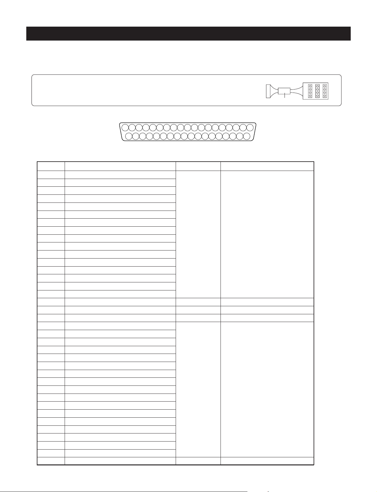
ALARMS/TRIGGER Connector and COM Connector
Ferrite core
DB 37
Terminal Board
ALARMS/TRIGGER Connector
See the Pin Configuration Table below for the functions of the various pins.
Note: When using the Terminal board
When using the Terminal board, please fix the provided Ferrite core to the cable.
Connector Pin Arrangement
Pin Configuration Table
12345678910111213141516171819
(DB37 pin connector)
202122232425262728293031323334353637
- 33 -
Pin No. Function
1 Alarm In 1
2 Alarm In 2
3 Alarm In 3
4 Alarm In 4
5 Alarm In 5
6 Alarm In 6
7 Alarm In 7
8 Alarm In 8
9 Alarm In 9
10 Alarm In 10
11 Alarm In 11
12 Alarm In 12
13 Alarm In 13
14 Alarm In 14
15 Alarm In 15
16 Alarm In 16
17 REC Trigger In
18 NC
19 GND
20 Alarm out 1
21 Alarm out 2
22 Alarm out 3
23 Alarm out 4
24 Alarm out 5
25 Alarm out 6
26 Alarm out 7
27 Alarm out 8
28 Alarm out 9
29 Alarm out 10
30 Alarm out 11
31 Alarm out 12
32 Alarm out 13
33 Alarm out 14
34 Alarm out 15
35 Alarm out 16
36 Alarm out
37 +5V
Input/Output Operation
Input • Normal Close, or Normal
Open, Logic level “Low”,
or Logic level “High”.
(Set in menu)
Input
–
–
Output Open Collector
–
Page 35
COM Connector
This is the RS-232C/RS-422 control connector. RS-232C or RS-422 settings are made using the internal switches of
this unit (Factory setting is RS-232C).
Remote control operation of this unit and changes of the setting contents can be performed by serial communications.
For details, please consult your dealer.
(Communications Protocol)
• Transfer speed: 4800 bps, 9600 bps, 19200 bps
• Stop bit: 1 bit
• Start bit: 1 bit
• Data length: 8 bits (LSB first)
• Parity: None
(Connections)
D-SUB 9-Pin Connector
Pin No. Function
1 ( NC )
5 4 3 2 1
9 8 7 6
2 RS-232C RXD
3 RS-232C TXD
4 ( NC )
5 GND
6
RS-422 TXD ( Factory setting: open)
7
RS-422 RXD ( Factory setting: open)
8
RS-422 TXD ( Factory setting: open)
9
RS-422 RXD ( Factory setting: open)
(NC: No Connection)
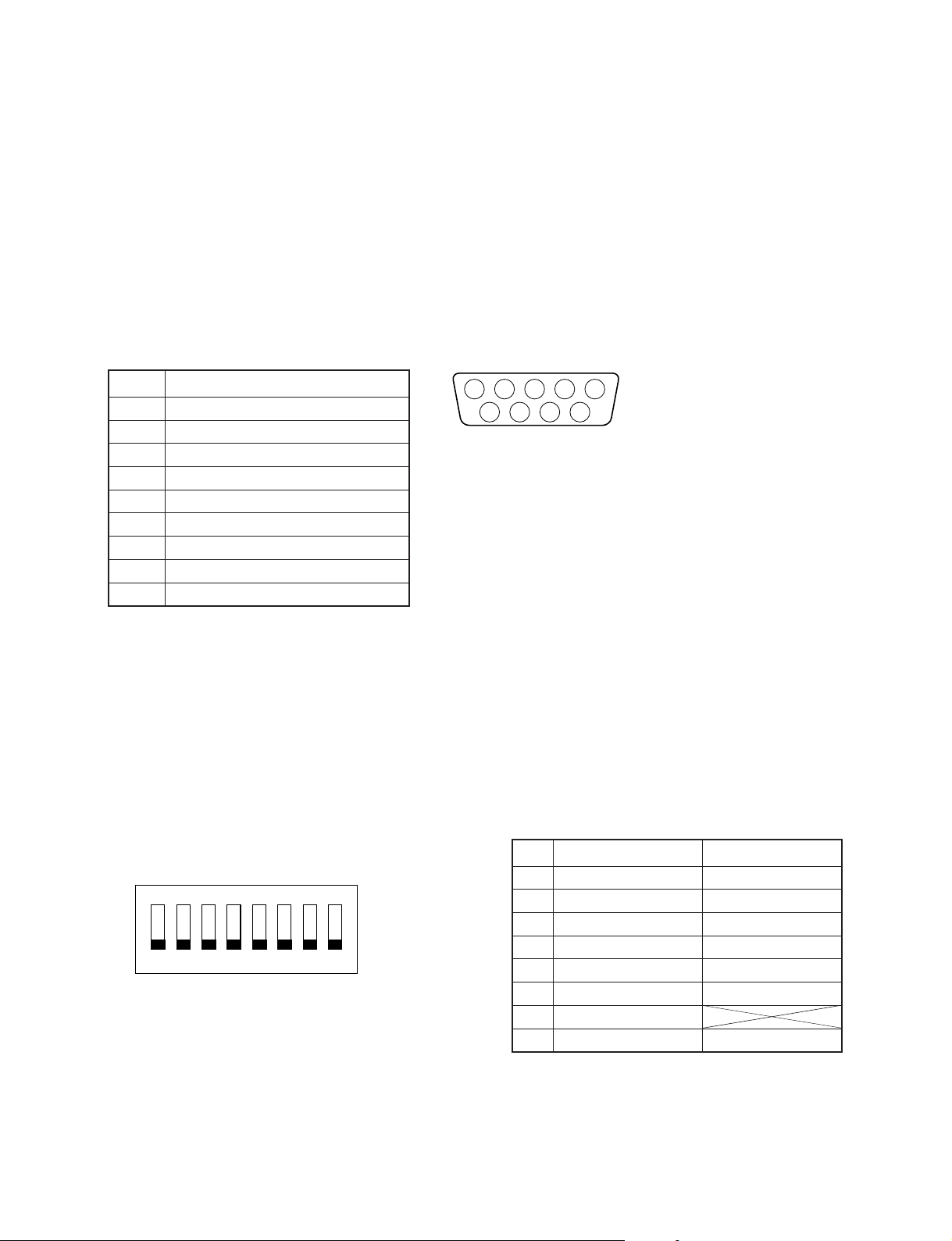
Changing the Internal Switch
At time of shipping, this unit is set for the NTSC system and the communications profile is set to RS-232C. By
changing the internal settings of this unit, the settings can be changed to the PAL system or RS-422 communications
profile.
Setting Method
(1) Disconnect the AC adapter. Remove the 8 screws from the sides and the 2 screws from the rear, then take off the
top cover.
(2) Set switch (S501) on the main circuit board according to the settings of the table below.
No. OFF Side ON Side
1 RS-232C RS-422
ON
2 RS-232C RS-422
3 RS-232C RS-422
12345678
4 RS-232C RS-422
5 RS-232C RS-422
S501
6
7 (*1)
8 NTSC P AL
Note
*1: Make sure to set to “OFF”
(3) Attach the top cover and tighten the screws in their original positions.
(4) Connect to the AC adapter.
RS-422 No termination
RS-422 T ermination
- 34 -
Page 36

Signal Levels of Input/Output Terminals
Input/Output T erminal
• Alarm Input
• Moving picture
trigger input
5V
0V
3.3V
0V
Signal Level Internal Circuit (Equivalent)
DC3.3V
100ms or greater
Negative logical
signal input
32ms or greater
10ms or greater
10ms or greater
Inside
the main unit
Inside
the main
unit
220Ω
DC5V
47kΩ
4.7kΩ
4.7kΩ
22kΩ
To CMOS input
DC3.3V
10kΩ
• Alarm output
Maximun 5V DC, 20mA
Inside
the main unit
CMOS output
- 35 -
Page 37

Troubleshooting
Symptom
There is no image
Image is disturbed
Front panel buttons don’t function
Alarm signal is not being received
ALARM RESET button does not
function
Screen is not displayed properly
during VCR playback
Screen is disturbed during VCR
playback
VCR does not record properly
The time is off
Items to Check
• Is the power plug of the AC adapter securely plugged into
the power outlet?
• Are the cables properly connected?
• Perhaps the VCR direct mode has been set?
• Perhaps the menu mode has been set?
• Perhaps the alarm mode has been set?
• Perhaps the VCR direct mode has been set?
• Perhaps the menu screen has been set?
• It is possible that the unit is not in the alarm mode.
• Check the VCR mode tracking adjustment.
• While playing back a commercial, pre-recorded tape, set the
unit to the VCR direct mode.
• Check the direct playback image in VCR direct mode.
• The image might be disturbed when the VCR is set to a
special playback mode (e.g., cue, review).
• Check the menu settings.
• Are the connections with the VCR correct?
• Check the settings of the VCR deck.
• The clock of this unit has an accuracy of within one minute
per month. Please reset the time periodically.
- 36 -
Page 38

Specifications
Power supply 5V DC 1.3A
External dimensions EIA 1U
17 x 1-3/4 x 14-3/4 inch (W x H x D), 430 x 44 x375 mm (W x H x D)
Weight 4.0 kg (8 lbs 13 oz)
Signal system Standard NTSC/PAL color television system
NTSC : 525 lines, 60 Fields/s
PAL : 625 lines, 50 Fields/s
Camera input BNC, 1.0V(p-p), 75 ohm Unbalanced Luminance signal
Camera output BNC, 1.0V(p-p), 75 ohm Unbalanced Luminance signal
(Loop Through)
Monitor output BNC, S-video, 1.0V(p-p), 75 ohm Unbalanced Luminance signal
VCR input BNC, S-video, 1.0Vp-p), 75 ohm Unbalanced Luminance signal
VCR output BNC, S-video, 1.0V(p-p), 75 ohm Unbalanced Luminance signal
Digital Sampling 711 x 460 NTSC, 711 x 562 PAL
Operating conditions Temperature: 32°F to 104°F (0°C to 40°C)
Humidity: less than 90%
Connector section
Alarm input DB37, Ground input: 0V to 0.5V
Alarm output DB37, Open/Short, less than 20mA
Recording trigger input DB37, 0V/5V pulse signal
Communication port DB9 (RS232C or RS422)
Design and specifications are subject to change without notice.
Note: Please acknowledge that we reserve the night to make changes in product performance or specifications
without prior notice. Also please note that we bear no responsibility for mistakes, misprints or omissions of
the instruction manual.
Accessories
• Instruction manual (JK-MX16A) (1)
• Quick reference guide (1)
• Terminal board (1)
• Ferrite core (1)
• Screw (2)
• Rack mount ear (EIA) (2)
• AC adapter (1)
• Instruction manual (AC adapter) (1)
- 37 -
Page 39

LIMITED WARRANTY
LIMITED WARRANTY
MULTIPLEXER
The Imaging Systems Division of Toshiba America Information Systems, Inc. (“ISD”) makes the following limited warranties with regard to
this MULTIPLEXER (“Product”). These limited warranties extend to the Original End-User (“You[r]”).
One (1) Year Limited Warranty of Labor and Parts ISD warrants that this Product will perform in accordance with specifications for a
period of one (1) year from the date of purchase by the Original End-User. During this one (1) year period, ISD will repair or replace the
Product, if it does not perform as warranted. In order to take advantage of this Limited Warranty, You must: (a) deliver the Product to an
ISD Authorized Service Provider (“ASP”); and (b) pay all transportation and insurance charges for shipment of the Product to the ASP.
ISD reserves the right to substitute factory refurbished parts in place of those in need of repair.
Instruction Manual (Owner’s Manual): You should read the Instruction Manual (Owner’s Manual) thoroughly before operating this Product.
Before seeking warranty service, you should check the troubleshooting guide in the Instruction Manual (Owner’s Manual) and follow the
instructions to correct the problem.
How to Obtain Warranty Service – Step-by-step Procedures: To obtain warranty service, You should:
1.Contact Toshiba at (877) 855 – 1349 for operation or installation assistance. (877) 855 – 1FIX
2.Contact an ASP for warranty service within thirty (30) days after the Product fails to comply with specifications.
2.Arrange for shipment of the Product to a Toshiba Authorized Service Provider.
3.Securely pack the Product in the original carton and external shipping pack, include a letter explaining the problem with a copy of the
bill of sale or proof of purchase.
4.Prepay all transportation and insurance costs.
Questions? If you have any questions, please check our web site at http://www.toshiba.com/taisisd/security/
Your Responsibilities: This Limited W arranty is subject to the following conditions:
1.You must provide the bill of sale or proof of purchase at the time that warranty service is required.
2.You must notify an ASP within thirty (30) days after you discover that the product does not perform in accordance with specifications
during the Limited Warranty period.
3.All Warranty Service of this product must be by an ISD Authorized Service Provider.
4.You must pack the Product in its original carton using the original packing material, then insert the original carton containing the
Product into another carton with additional packing material before shipping the Product to an ASP.
DISCLAIMERS:
ALL OTHER EXPRESS OR IMPLIED WARRANTIES ON THIS PRODUCT, INCLUDING THE IMPLIED WARRANTIES OF
MERCHANTABILITY AND FITNESS FOR A PARTICULAR PURPOSE, ARE HEREBY DISCLAIMED. SOME STATES DO NOT
ALLOW THE EXCLUSION OF IMPLIED WARRANTIES OR LIMITATIONS ON HOW LONG AN IMPLIED WARRANTY LASTS, SO
THE ABOVE LIMITATIONS MAY NOT APPLY TO YOU.
IF THIS PRODUCT IS NOT IN GOOD WORKING ORDER AS WARRANTED ABOVE, YOUR SOLE AND EXCLUSIVE REMEDY
SHALL BE THE REPAIR OR REPLACEMENT OF THE PRODUCT. IN NO EVENT WILL ISD OR ITS PARENT COMPANY OR ANY
ASP BE LIABLE TO YOU OR ANY THIRD PARTY FOR ANY DAMAGES IN EXCESS OF THE PURCHASE PRICE OF THE
PRODUCT. THIS LIMITATION APPLIES TO DAMAGES OF ANY KIND, INCLUDING ANY DIRECT OR INDIRECT DAMAGES, LOST
PROFITS, LOST SAVINGS OR OTHER SPECIAL, INCIDENTAL, EXEMPLARY OR CONSEQUENTIAL DAMAGES, WHETHER FOR
BREACH OF CONTRACT, TORT OR OTHERWISE, OR WHETHER ARISING OUT OF THE USE OF OR INABILITY TO USE SUCH
PRODUCT, EVEN IF TAIS, ITS PARENT COMPANY, OR AN ASP HAS BEEN ADVISED OF THE POSSIBILITY OF SUCH
DAMAGES OR OF ANY CLAIM BY ANY OTHER PARTY. SOME STATES DO NOT ALLOW THE EXCLUSION OR LIMITATION OF
INCIDENTAL OR CONSEQUENTIAL DAMAGES FOR SOME PRODUCTS, SO THE ABOVE LIMITATINS OR EXCLUSIONS MAY
NOT APPL Y TO YOU.
THIS WARRANTY GIVES YOU SPECIFIC LEGAL RIGHTS, AND YOU MAY ALSO HAVE OTHER RIGHTS WHICH MAY VARY
FROM STATE TO STATE.
THIS LIMITED WARRANTY SHALL BE VOID IF THE PRODUCT OR PARTS HAVE BEEN SUBJECTED TO MISUSE, ABUSE,
ACCIDENT, IMPROPER INSTALLATION, IMPROPER MAINTENANCE, OR USE IN VIOLATION OF ISD’S WRITTEN INSTRUCTIONS, OR WHERE THE PRODUCT HAS BEEN ALTERED OR MODIFIED WITHOUT ISD’S PRIOR AUTHORIZATION, OR UPON
THE REMOVAL OR ALTERATION OF ISD’S FACTORY SERIAL NUMBER. LABOR SERVICE CHARGES FOR PRODUCT
INSTALLATION, SET UP AND ADJUSTMENT OF CONTROLS ARE NOT COVERED BY THIS LIMITED WARRANTY.
No person, agent, distributor, dealer, authorized service provider, or company is authorized to change, modify, or extend the terms of this
Limited Warranty in any manner whatsoever. The time within which an action must be commenced to enforce any obligation of ISD arising
under this Limited Warranty or under any statute, or law of the United States or any state thereof, is hereby limited to one (1) year from the
date You discover or should have disco vered the problem. This limitation does not apply to implied warranties arising under state law.
Some states do not permit limitation of the time within which You may bring an action beyond the limits provided by state law, so the above
provision may not apply to You. This Limited Warranty gives You specific legal rights and You may also have other rights which vary from
state to state.
TOSHIBA AMERICA INFORMATION SYSTEMS, INC.
Imaging Systems Division
Printed in Japan
23565074
- 38 -
 Loading...