

Page 1
TOSHIBA
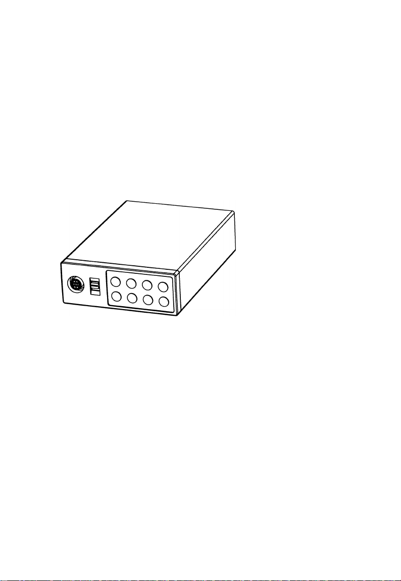
CAMERA CONTROL UNIT
IK-TU51 eu
INSTRUCTION MANUAL
For Customer Use
Enter below the Serial No.
which is located on the
bottom of the cabinet. Retain
this information for future ref
erence.
Model No.: IK-TU51CU
Serial No.:
WARNING
This is a Class A of EN55022 product. In a domestic environment this product may cause radio
interference in which case the user may be required to take adequate measures.
INFORMATION
This equipment has been tested and found to comply with the limits for a Class A digital device, pursu
ant to Part 15 of the FCC Rules. These limits are designed to provide reasonable protection against
harmful interference when the equipment is operated in a commercial environment. This equipment
generates, uses, and can radiate radio frequency energy and, if not installed and used in accordance
with the instruction manual, may cause harmful interference to radio communications. Operation of this
equipment in a residential area is likely to cause harmful interference in which case the user will be
required to correct the Interference at his own expense.
USER-INSTALLER CAUTION: Your authority to operate this FCC verified equipment could be voided If
you make changes or modifications not expressly approved by the party responsible for compliance to
Part 15 of the FCC Rules.
This Class A digital apparatus complies with Canadian ICES-003.
Cet appareil numérique de la classe A est comforme à la norme NMB-003 du Canada.
Page 2

SAFETY PRECAUTIONS
Read the following safety precautions carefully before using the product. These instructions
contain valuable Information on safe and proper use that will prevent harm and damage to the
operator and other persons. Make sure that you fully understand the following details (indications,
graphic symbols) before proceeding to the main descriptions in this manual.
Indication definitions
Indication
This indicates that Ignoring this la
A
Warning
A
Caution
*1: Bodily injury means Injuries, burns and elec
tric shock which does not require hospitaliza
tion or prolonged treatment.
*2: Physical damage means extended harm to home, household effects.
o
bel and/or misoperation of the prod
uct may cause serious personal In
jury or even death.
This indicates that ignoring this la
bel and/or misoperation of the prod
uct may cause personal injury*^ and/
or material damage*^.
Do not use the product when abnormality occurs.
The use in the abnormality status such as emitting smoke from the product, smelling burn
ing, being damaged by drop, invasion of foreign objects inside the product, etc., may cause
fire and/or electric shock. Be always sure to disconnect the power plug from the electrical
outlet (socket) at once and contact your dealer.
Do not install the product where splashing of water may occur, such as outdoor, a bathroom, etc.
This may cause fire and/or electric shock.
Do not repair, disassemble and/or modify by yourself.
This may cause fire and/or electric shock. Be always sure to contact your dealer for internal
repair, check and cleaning of the product.
Meaning
/iWOrnina
Graphic symbol definitions
Symbol
Indicates a prohibited action that
must not be carried out. The actual
0
•
prohibited action is indicated in the
symbol or nearby graphically or de
scribed in text.
Indicates a mandatory action that
must be carried out surely. The ac
tual mandatory action is indicated in
the symbol or nearby graphically or
described In text.
Meaning
(S)
0
Keep the rated voltage for the product.
The use of power supply voltage except for its rated voltage may cause fire and/or electrical
shock. Please refer to ’’5.CONNECTIONS”.
Do not put a vessel(s) filled with a liquid (flower vase, etc.).
If a liquid enters the product, a fire and/or electric shock may occur.
Do not put the product in an unstable, slanting and/or vibrated place.
Drop and/or fail of the product may cause injury.
Do not touch power or TV antenna cords during a thunderstorm.
This might cacuse electric shock.
Page 3

<S)'
0‘
0
0-
Keep the followings when installing.
• Do not put the product on a Inflammable material such as carpet or blanket.
• Do not put the product in a narrow space, since the heat generated from the product
may be difficult to emanate.
• Do not put a inflammable material on the product.
If you do not keep above, the heat generated by the product may cause fire.
Do not put the product in direct sunshine and/or high temperature.
The temperature rise inside the product may cause fire.
Do not put the product In a moist or dusty place such as a bathroom, a place close to a humidifier, etc.
This may cause fire and/or electric shock.
Do not put the product in a moist, soot and/or dusty place such as a kitchen, etc.
Do not put the product where a soot and steam may occur, such as a kitchen, etc., or in a
dusty place. This may cause fire and/or electric shock.
Do not shoot the sun with the lens and do not put the lens in the place exposed to an intensive light, such as the sunshine, etc.
Focusing of the light may cause injury of eye and/or fire.
Do not put the product in your mouse and do not swallow it.
This may cause suffocation and/or injury.
Ask your dealer to perform a periodical check and internal cleaning.
Dust inside the product may cause fire and/or trouble. For check and cleaning cost, please
consult your dealer.
Page 4

TABLE OF CONTENTS
1. CAUTIONS ON USE AND INSTALLATION................................................................... 6
2. COMPONENTS................................................................................................................ 6
3. ITEMS CONTROLLED BY USING ON SCREEN DISPLAY
4. NAMES AND FUNCTIONS............................................................................................. 8
5. CONNECTION.................................................................................................................10
5.1 Standard Connection................................................................................................. 10
5.2 Cautions on Connection............................................................................................ 10
5.3 Connection on Back Panel........................................................................................ 10
5.3A Connector Pin Assignments..................................................................................... 11
6. OPERATION...................................................................................................................12
6.1 Automatic Black Balance........................................................................................... 12
6.2 White Balance............................................................................................................ 13
6.3 Scene File.................................................................................................................. 15
6.4 Gain............................................................................................................................ 15
6.5 Shading Correction................................................................................................... 16
6.6 Freeze Operation....................................................................................................... 17
7. MODE SETTING BY ON SCREEN DISPLAY...............................................................17
7.1 Using the Menus........................................................................................................ 17
7.2 Menus........................................................................................................................ 19
(1) SHUTTER (Electronic shutter)................................................................................... 19
(1.1) Changing each setting in AUTO mode...............................................................20
(1.2) Changing each setting in MANUAL mode..........................................................22
(1.3) Changing each setting in SS(synchro. scan) mode
(1.4) Changing each setting in EXT TRIG mode
(1.4.1) Changing each setting in 1 PULSE SNR mode
(1.4.2) Changing each setting in 1 PULSE SR mode.................................................25
(1.4.3) Changing each setting in 2 PULSE mode.......................................................26
(1.4.4) Changing each setting in RS232C mode
(2) GAIN (Video gain).......................................................................................................27
(2.1) Changing the maximum gain in AUTO (Automatic gain control) mode
(2.2) Changing gain in MANUAL mode.......................................................................28
(3) WHT BAL (White balance)..........................................................................................29
(3.1) Changing the AWB (Automatic White Balance)mode setting
(3.2) Changing the ATW (Automatic Trace White Balance)mode setting
(3.3) Changing the MANUAL mode setting................................................................31
(4) PROCESS (Process)................................................................................................. 32
(4.1) Changing the gamma correction ON/OFF..........................................................32
(4.2) Changing gamma correction level......................................................................32
(4.3) Changing black gamma correction level.............................................................33
(4.4) Changing two-dimension low pass filter
(4.5) Changing detail (outline) gain.............................................................................33
(4.6) Changing detail boost frequency
(4.7) Changing master pedestal..................................................................................34
(4.8) Changing chroma gain........................................................................................34
(4.9) Changing DNR(Digital Noise Reduction)............................................................34
(5) MATRIX(Matrix color correction).................................................................................35
(5.1) Changing MATRIX color correction ON/OFF
(5.2) Changing each of MATRIX setting
(6) SYNC.......................................................................................................................... 36
(6.1) INT screen...........................................................................................................36
(6.2) Changing EXT setting.........................................................................................36
.............................................................
........................................................................
.....................................................................
.........................................
...........................................
........................................................
..............................................
........................................................
............................
..................
.....................................................
.............
7
23
24
24
27
28
29
30
33
33
35
35
Page 5

(7) OPTION....................................................................................................................... 37
(7.1) Chaging OUTPUT1 output
(7.2) Chaging OUTPUT2 output
(7.3) Chaging shading correction mode.......................................................................37
(7.4) Chaging manual shading correction setting........................................................37
(7.5) Chaging RGB SYNC............................................................................................37
(7.6) Chaging FREEZE DISP setting...........................................................................38
(7.7) Chaging Negative/Positive inversion switch
(7.8) Chaging detail signal output................................................................................38
(7.9) Chaging RS232C communication baud rate setting...........................................38
(8) Setting USER area.......................................................................................................38
(9) Setting to factory setting status
7.3 External Sync..............................................................................................................40
(1) External sync signal input conditions
(2) External sync frequency range
(3) Using the unit with external sync signal......................................................................41
(3.1) H (horizontal) phase adjustment.........................................................................41
(3.2) SC (Sub carrier) phase afjustment
7.4 Synchro. Scan Operation............................................................................................42
(1) Setting by 1H............................................................................................................... 42
(2) Setting by the frame.................................................................................................... 42
7.5 EXT TRIG(External trigger)
(1) 1 PULSE SNR (1 PULSE Sync Non Reset)
(2) 1 PULSE SR (1 PULSE Sync Reset)......................................................................... 44
(3) 2 PULSE...................................................................................................................... 45
(4) RS232C....................................................................................................................... 47
7.6 Freeze Operation by Trigger Input..............................................................................48
7.7 Digital output................................................................................................................49
(1) Sync pulse timing....................................................................................................... 49
8. BEFORE MAKING A SERVICE CALL...........................................................................50
9. SPECIFICATIONS..........................................................................................................51
10. EXTERNAL APPEARANCE DIAGRAM......................................................................52
.................................................................................
.................................................................................
.......................................................
...................................................................................
..........................................................................
...................................................................................
.....................................................................
......
..................................................................................43
...............................................................
37
37
38
40
40
41
41
43
Page 6

1. CAUTIONS ON USE AND INSTALLATION
•Carefully handle the units.
Do not drop, or give a strong shock or vibration
to the camera. This may cause problems.
Treat the camera cables carefully to prevent
cable problems, such as cable breakdown and
loosened connections.
•Do not shoot intense light.
If there is an intense light at a location on the
screen such as a spot light, a blooming and
smearing may occur.
When intense light enters, vertical stripes may
appear on the screen. This is not a malfunction.
Ghosts may occur when there is an intense light
near the object. In this case, change the
shooting angle.
•Install the camera in a location free
from noise.
If the camera or the cables are located near
power utility lines or a TV, etc. undesirable
noise may appear on the screen. In such a
case, try to change the location of the camera
or the cable wiring.
•Moire
When thin stripe patterns are shooted, stripe
patterns that are not actually there (moire) may
appears as interference stripes. This is not a
malfunction.
•Operating ambient temperature and humidity.
Do not use the camera in places where temperature
and humidity exceed the specifications. Picture
quality will lower and internal parts may be
damaged.
Be particularly careful when using in places
exposed to direct sunlight. When shooting in hot
places, depending on the conditions of the object
and the camera (for example when the gain is
increased), noise in the form of vertical strips or
white dots may occur. This is not a malfunction.
•Handling of the camera head and
protection cap.
Keep the camera head and the protection cap away
from children. Children may put them into mouth or
swallow them accidentally. The protection cap
protects the image sensing plane when the lens is
removed from the camera head, do not throw away.
•When not using the camera for a longtime.
Turn off the camera power switch and stop
supplying power.
•When cleaning the camera
Always turn off the power and make a cleaning with
a piece of dry cloth. If necessary, gently wipe with a
cloth dampened with thinned detergent. Do not use
benzine, alcohol, thinner, etc. If used, coating and
printed letters may be discolored. When cleaning
the lens, use a lens cleaning paper, etc.
2. COMPONENTS
(1 ) Camera Control Unit
(2) Accessories
(a) Instruction manual.
.........
Page 7
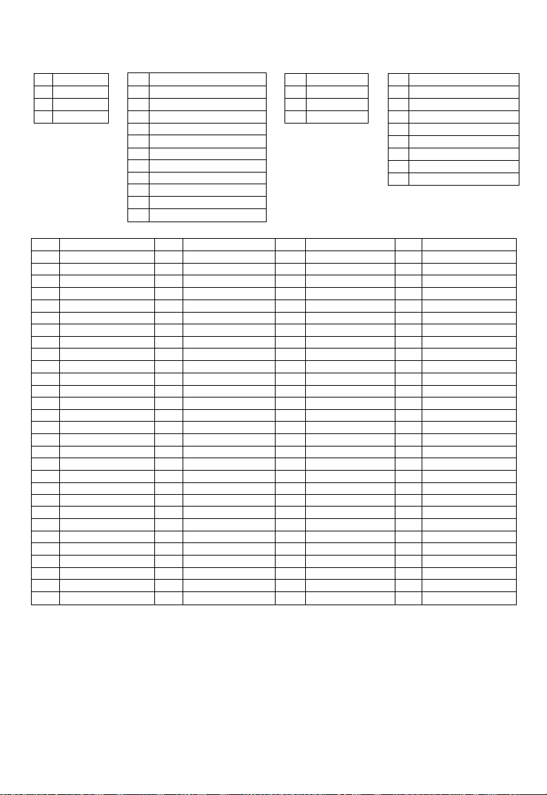
3. ITEMS CONTROLLED BY USING ON SCREEN DISPLAY
Item
MODE
EXT TRIG
AUTO level
AUTO peak/average
AUTO response speed
AUTO area PRESET A, PRESET B, PRESET C, PRESET D,
m
O
5
MANUAL speed
o’
CO
3- Syncro.
scan
CD
Storage mode FLD, FRM
FLD
FRM
Freeze operation
AUTO. MANUAL, SS, EXT TRIG
1 PULSE SNR, 1 PULSE SR, 2PULSE, RS232C
-100 - 0 - 100
00 :10 - 05 : 05 - 10 : 00
1-5-10
PRESET E, USER
(USER area is possible to set in 64 zones)
OFF, 1/IOOs. 1/250S, 1/500s, 1/IOOOs, 1/2000S,
1/4000s, 1/10000s
1/525H to 260/525H, OFF, 1FRM to 255FRM
1/525H to 260/525H, OFF, 2FRM to 256FRM
FRONT, TRIG ^ .TRIG^
Trigger
(1 PULSE SNR/SR)
Trlgger(2PULSE)
1 PULSE exposure time
AUTO maximum gain
MANUAL gain
Jl—n_ ,J L
0.06ms to 16ms
OdB to 20dB
OdB to 20dB
Color temperature 3200K, 5600K
AWB R PAINT -10 - 0 - 10
AWB B PAINT -10 - 0 - 10
g;
AWB area PRESET A, PRESET B, PRESET C, PRESET D,
CD
CT
0>
03
3
ATW R PAINT
o
CD
ATW B PAINT -10 - 0 - 10
MANUAL R GAIN
PRESET E, USER
(USER area is possible to set in 64 zones)
-10 - 0 - 10
-100 - 0 - 100
MANUAL B GAIN -100 - 0 - 100
Gamma correction switching
ON. OFF
Gamma correction level -10 - 0 - 10
Black gamma
Two-dimension low pass
LOW, NORMAL, HIGH
ON, OFF
Filter (2D LPF)
Detail gain
-7(OFF) - 0 - 7
Detail boost freguency LOW, NORMAL, HIGH
Master pedestal -50 - 0 - 50
Chroma gain
-128 - 0 - 127
Digital noise reduction(DNR) ON. OFF
Correction ON/OFF ON, OFF
R hue
R gain -15 - 0 - 15
S
Q3_
G hue
3.
X
G gain -15 - 0 - 15
o
o
B hue
o
B gain -15 - 0 - 15
o
o
Ye hue
CD
o
Ye gain
5
Cy hue
3
-15 - 0 - 15
-15 - 0 - 15
-15 - 0 - 15
-15 - 0 - 15
-15 - 0 - 15
-15 - 0 - 15
Cy gain -15 - 0 - 15
Mg hue -15 - 0 - 15
Mg gain
-15 - 0 - 15
Available selections
Preset vaiue
(Factory setting)
MANUAL
1 PULSE SNR
05
PRESETA
FRONT
3200K
PRESETA
NORMAL
NORMAL
JK-TU52H use
0
0
3
3
0
2
0
2
0
0
0
0
0
: 05
5
OFF
OFF
FLD
JUJl-
16ms
lOdB
OdB
0
0
0
0
0
0
ON
0
OFF
0
0
0
OFF
ON
JK-TU53H use
0
0
0
0
0
-1
0
-1
0
0
0
0
Page 8
Item
H phase adjustment
Ext.
SC 0/180 0. 180 0
Sync.
SC phase adjustment
OUTPUT 1
Shading correction mode
Manual shading correction
RGB SYNC
FREEZE DISP
Negative/Positive inversion
Detail signal output
RS232C baud rate 9600bps, 19200bps
-100 - 0 - 100
-128 - 0 - 127
RGB, Y/P^P„ RGB
2
VBS, Y/C VBS
SET, MANUAL, OFF OFF
-128 - 0 - 127
G, ALL ON, ALL OFF
ON, OFF
NEGA, POSI
ON, OFF
Available selections
4. NAMES AND FUNCTIONS
Preset value
(Factory setting)
0
0
0
G
ON
POSI
OFF
9600bps
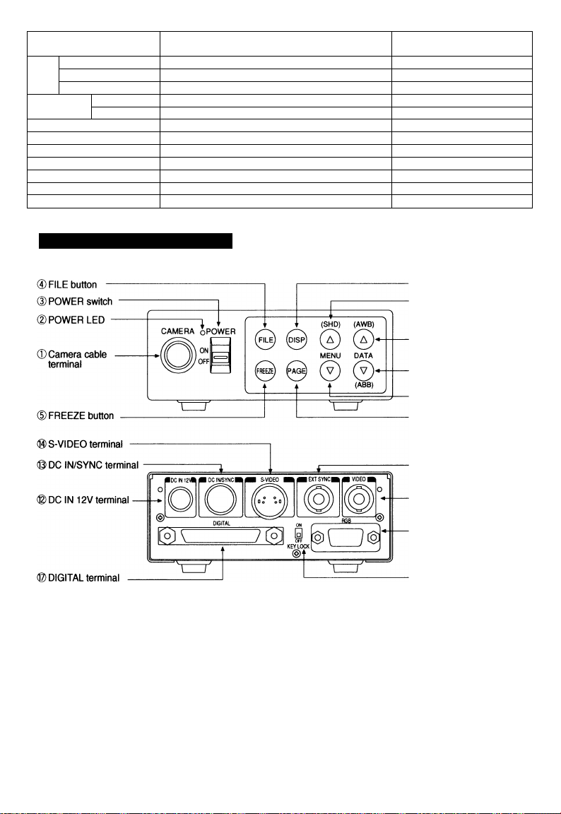
(D DISP button
©MENU UP
(SHD) button
D DATA UP
(AWB) button
d3) DATA DOWN
(ABB) button
(DMENU UP(SHD) botton
(Z)PAGE button
©EXT.SYNC terminal
(©VIDEO terminal
© RGB terminal
©KEY LOCK switch
Page 9

©Camera cable terminal
©POWER LED
©POWER switch
0FILE button
©FREEZE button
©DISP button
©PAGE button
©MENU UP(SHD)button
©MENU DOWN button
©DATA UP(AWB)button
©DATA DOWN
(ABB) button
©DC IN 12V terminal
©DC IN/SYNC terminal
©S—VIDEO terminal
©EXT. SYNC terminal
©VIDEO terminal
©DIGITAL terminal
©KEY LOCK switch
©RGB terminal
The camera cable is connected.
Lights when the power is turned on.
Turns on or off the power supply.
Used when switching the scene files.
Used when switching to the freeze menu and when returning from the freeze
menu to the camera menu.
Used when switching the display.
Used when switching to the menu and when selecting the menus.
Select the function to be confirmed or changed on the menu. (Also used when
performing the auto shading correction.)
Select to confirm the function or to change the menu.
Changes the value of the function selected by the MENU (UP/DOWN) button.
(Also used when using AWB.)
Changes the value of the function selected by the MENU (UP/DOWN) button.
(Also used when using ABB.)
Accept a DC power input (12V).
HD and VD signals are input/output. When the random trigger operation is
used, the trigger signal is input and the index signal is output.
Outputs Y (luminance) and C (color) signals.
Used when the camera output signal is synchronized by the external signal.
(BNC connector)
Outputs VBS output. Connected to a monitor, VTR, etc. (BNC connector)
LVDS format digital video signal output and control signal input/output
terminal. This terminal also includes an RS232C format external control pin.
Enables/disables buttons 0 to ©.
Used as the connector terminal for Y/C or VBS output, RGB or Y/Pr/Pb output,
and SYNC output.
9
Page 10
5. CONNECTION
5. 1 Standard Connection
Lens
Camera cable
(option)
Camera head
(option)
5. 2 Caution on Connection
IK-TU51CU
Camera
Control unit
VIDEO Cable 75 Q
Coaxial
DC IN 12V
DC power
supply
monitor
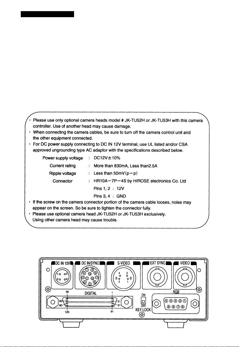
5. 3 Connection on Back Panel
Back panel view
10
Page 11
5. 3A Connector Pin Assignments
DC IN 12V
1 +12V
+12V
2
GND
3
4 GND
DC IN/SYNC
1 GND
2 +12V
GND(for INDEX)
3
4 INDEX
GND(for HD)
5
HD OUT
6
S-VIDEO RGB
1 GND
2
GND
Y
3
4
C
7 VD OUT
GND(for TRIGGER)
8
TRIGGER
9
VD IN
10
11
HD IN
12 GND(for VD)
DIGITAL
1 RO (+) 31 RO (-)
2
R1 (+)
3
R2 (+)
4
R3 (+)
5
R4(+)
6
R5 (+)
7
R6 (+)
8
R7 (+)
9 R8 (+) 39
10
R9(+)
11 GO (+)
12
G1 (+)
G2 (+)
13
14
G3 (+)
G4 (+)
15
16 G5 {+)
17
G6(+)
18 G7 (+)
19 G8 (+)
20 G9(+) 50
21
B0(+) 51 BO(-)
22
B1 (+)
23
B2(H-)
24
B3 (+) 54
B4(+)
25
32
R1 (-)
33 R2 (-)
34
R3 (-)
35
R4 (-)
36
R5 (-)
37 R6 (-) 67 RESERVE(OUT+)
38
R7(-)
R8 (-)
40
R9 (-)
41
GO (-) 71 GND
42
G1 (-)
43 G2 (-)
44
G3 (-) 74 GND
G4 (-)
45
46 G5 (-) 76 GND
47
G6(-) 77 GND
G7 (-)
48
49 G8 (-) 79 GND
G9(-) 80 GND
52
B1 (-)
B2(.)
53
B3 (-)
55 B4(-)
26 B5 (+) 56 B5 (-)
27
B6(+)
B7(+)
28
29
B8 (+) 59
30 B9 (+)
57
B6 (-)
B7(-)
58
B8 {-) 89
60 B9 (-)
GND
61
62 PIXEL CLK (+)
FRAME EN (+)
63
64
FIELD ID (+) 94
LINE EN (+)
65
66 TRIGGER D (+)
GND
68
GND
69
70 GND
72 GND
GND
73
GND
75
GND
78
81 GND 111
82 GND
GND
83
84
GND 114
GND
85
GND
86
87 TXD
RXD
88
GND
GND
90
* When using pins to remote(pins 87 to 89), please consult with your dealer.
1 GND(for VBS,Y/C)
2
GND(for R/G/B.Y/Pr/Pb)
3
r/Pr out
4
GA'OUT
5
b/Pb out
6 VBSA' OUT
7
SYNC OUT
8 GND(for SYNC)
9 -/C OUT
GND
91
92
PIXEL CLK (-)
93 FRAME EN (-)
FIELD ID (-)
95 LINE EN (-)
96 TRIGGER D (-)
97 RESERVE(OUT-)
GND
98
99 GND
100 GND
101 GND
102
GND
103 GND
104 GND
GND
105
106 GND
107
GND
108 GND
109 GND
GND
110
GND
112 GND
113 GND
GND
GND
115
116 GND
117
NC
118 NC
119 NC
120 GND
Precautions on DIGITAL terminal:
* Interference occurring inside the cable may accidentally activate the Trigger if the TRIGGER D
inputs (pins 66 and 96) are open.
If the TRIGGER D input is not used, the TRiGGER D input pin should be either not connected or
connected to RESERVE output pin (pins 67 and 97) ie: (connect pin 66 to pin 67 and pin 96 to 97).
* The RESERVE pins (pins 67 and 97) are provided for an additionai output. If unused they should
be OPEN or connected to Trigger D.
NC pins (pins 117 to 119) should be left OPEN.
V:
11
Page 12

6. OPERATION
(i) Referring to the item “ 5. CONNECTION”, connect each equipment correctly.
(D Turn on the connected equipment and the camera.
(D When using the camera for the first time and when replacing the camera cable and the camera head, be
sure to operate the ABB adjustment in advance, referring to the item “6.1 Automatic Black Balance”.
0 Facing the lens to the object, operate the lens iris adjustment, focus adjustment, etc.
(E> Referring to the item “6.2 White Balance”, operate the adjustment.
(D Referring to the items “6.3 Scene File, 6.4 Gain, 7. MODE SETTING BY ON SCREEN DISPLAY”, select
the necessary items.
6. 1 Automatic Black Balance
Black balance adjustment is necessary to get the correct black picture level.
• Close the lens iris.
• If the color bar pattern is displayed on the screen or if the index menu/menu is displayed, press the
[DISP] button to disable the color bar pattern or the character display. If the camera is in Freeze Mode,
perform the cancellation procedure (refer to the item “6.6 Freeze Operation”) to return the camera to Live
Image Mode.
• Hold the [DATA DOWN] button for approx. 1 second.
• When the black balance adjustment operation starts, the character ABB blinks on the screen.
• When the black balance adjustment operation finishes, the character ABB ends blinking and the result
appears for approx. 1 second.
Display Meaning
ABB OK
ABB NG
CLOSE LENS
ABB NG
Automatic black balance adjustment finished correctly.
Automatic black balance adjustment cannot be performed because the lens iris
is open. Close the lens iris.
Automatic black balance adjustment cannot be performed.
Operate the automatic black balance again.
12
Page 13

6. 2 White Balance
For the white balance adjustment for this unit, ATW (Automatic Trace White balance), AWB (Automatic
White Balance) and MANUAL (Manual white balance) adjustments are provided. Referring to the items “7.2
(3) WHT BAL (White balance), 7. MODE SETTING BY ON SCREEN DISPLAY”, select the desired mode.
(Automatic Trace White
Camera measures the object
Outline
Features
Notes
0 AWB(Automatic white balance)
• Set the MODE to AWB on the WHT BAL menu.
Perform the C.TEMP (color temperature conversion) setting, if necessary.
(Refer to the item “7.2 (3) WHT BAL (White balance)”.)
r3200K: Appropriate for Indoor shooting.
L5600K: Appropriate for outdoor shooting.
■ If the color bar pattern is displayed on the screen or if the index menu/menu is displayed, press the [DISP]
button to disable the color bar pattern or the character display on the menu. If the camera Is in Freeze
Mode, perform the cancellation procedure (refer to the item “6.6 Freeze Operation”) to return the camera to
Live Image Mode.
■ Shoot a known white object entirely in the area set by the AWB menu (refer to the item “7.2 (3) (3.1) (d)
Changing AWB zone area”) and push [DATA UP] button for approx. 1 second.
• The character AWB blinks on the screen when the AWB starts.
• The character AWB ends blinking when the AWB finishes, and the result is displayed for approx. 1 second.
color temperature and
adjust the white balance
automatically.
Traces variations of color
temperature and adjusts
the white balance automati
cally.
If an illumination is low,
white balance may not be
corrected. When the shutter
mode is EXT TRIG or long
the long period exposure
mode, ATW is not available.
ATW
Balance)
________
(Automatic White Balance)
Adjust white balance by
displaying the white object
inside the area set by AWB
menu and pressing the
[DATA UP] button.________
Measurement accuracy is
higher than ATW. This
mode is effective when
shooting under less varia
tions of color temperature.
When the shutter mode is
EXT TRIG, AWB is not avalable.
AWB
MANUAL
(Manual White Balance)
Adjust the white balance
manually using the WHT
BAL menu while shooting
the white object.
Artificial white balance
setting can be set. The
manual adjustment Is most
effective under shooting
condition with no color
temperature variation.
Adjustment is performed by
confirming with a vector
scope.
13
Page 14

Display
AWB OK Automatic white balance adjustment finished correctly.
AWB NG
LEVEL LOW
AWB NG
LEVEL HIGH
AWB NG
C. TEMP LOW
AWB NG
C. TEMP HIGH
AWB NG
NOT AVAILABLE
AWB NG
(D MANUAL(Manual white balance)
• Set the MODE to MANUAL on the WHT BAL menu.
(Refer to the item “7.2 (3) WHT BAL (white balance)”.)
• Shoot a known white object, adjust the white balance adjusting the levels of R GAIN and B GAIN on the
menu, confirming with a monitor or a vector scope.
(Refer to the item “7.2 (3) (3.3) Changing each setting in MANUAL mode”.)
Automatic white balance adjustment cannot be performed because the video level is
too low.
Set the video level properly.
Automatic white balance adjustment cannot be performed because the video level Is
too high.
Set the video level properly.
Automatic white balance adjustment cannot be performed because the color
temperature is too low.
If the C.TEMP is set to 5600K, set to 3200K.
If the message appears with the C.TEMP set to 3200K, change the illumination or
use a color temperature conversion filter.
Automatic white balance adjustment cannot be performed because the color
temperature is too high.
If the C.TEMP is set to 3200K, set to 5600K.
If the message appears with the C.TEMP set to 5600K, change the illumination or
use the color temperature conversion filter.
Automatic white balance adjustment cannot be performed because the shutter speed
mode is EXT TRIG mode.
Automatic white balance adjustment cannot be performed for other reasons. Such as
no white area is included in an object, etc.
Meaning
14
Page 15

6. 3 Scene File
Three scene files (A, B, C) are available as user memories for this unit. These are selectable depending on
shooting conditions. By using the [FILE] button, the camera operation is changed immediately from the
currently selected Scene File to the next. (Refer to the item “7. MODE SETTING BY ON SCREEN
DISPLAY”.)
• While any menu is displayed, pressing the [FILE] button will display the menu settings for the next Scene File:
FILE A -► FILE B FILE C
' When the [FILE] button is pressed while the camera is in live Image mode, the current scene file selection
at that time is displayed for approx. 3 seconds in the upper right comer of the screen. If the [FILE] button is
pressed again while the position is displayed, the scene file cycles as described above.
□
6. 4 Gain
When the image is dark even if the lens iris is open, change the gain (video gain) to get the proper video
level.
For the gain adjustment of the unit, AUTO (Automatic gain control), MANUAL (Manual), OFF (0 dB) modes
are provided. Select the mode on the GAIN menu. (Refer to the item “7.2 (2) GAIN (Video gain)”.)
0 AUTO(Automatic gain control)
When the output is low, the gain is automatically adjusted to a suitable video level.
The maximum value of the gain is 20dB, and can be set from 0 to 20dB in 1dB steps. (Refer to the Item
“7.2 (2) (2.1) Changing the maximum gain in AUTO (Automatic gain control) mode”.)
Video level (LEVEL), peak average value ratio (PEAK/AVE), and measurement light area (AREA) is same
as the setting on the automatic shutter. (Refer to the item “7.2 (1) (1.1) Changing each setting in AUTO
mode”.)
(D MANUAL(Manual gain)
Gain adjustment is performed on the GAIN menu. The adjustment range is from 0 to 20dB in IdB steps.
(Refer to the item “7.2 (2) (2.2) Changing the gain in MANUAL mode”.)
) OFF
Gain is fixed at 0 dB.
15
Page 16

6. 5 Shading Correction
Due to the lens used or the environmental condition, color shading may occur at the upper and lower side of
the screen. In this case, the shading correction can decrease the color shading. For the shading correction of
the unit, SET (Automatic shading correction), MANUAL (Manual shading correction), and OFF (no shading
correction) modes are provided. Select the mode on the OPTION menu. (Refer to the item “7.2 (7) (7.3)
Changing shading correction mode”.)
(i) SET(Auto shading)
• When the shutter speed mode Is set to EXT TRIG or the SS long period exposure mode, the automatic
shading correction cannot be performed.
• If the color bar pattern is displayed on the screen or if the index menu/menu is displayed, press the
[DISP] button to remove them from the screen. If the camera Is in Freeze Mode, perform the
cancellation procedure (refer to the item “6.6 Freeze Operation") to return the camera to Live Image
Mode.
• Push the [MENU UP] button for approx. 1 second.
• When the automatic shading correction operation starts, the character SHD blinks on the screen.
• When the automatic shading correction operation terminates, the character SHD ends blinking and the
result is displayed for approx. 1 second.
Display Meaning
SHD OK
SHOOK
LIMIT
SHD NG
LEVEL LOW
SHD NG
LEVEL HIGH
SHD NG
NOT AVAILABLE
Automatic shading correction operation terminated correctly.
Automatic shading correction operation terminated, however, the correction
necessary exceeds the camera’s range so the maximum possible value is applied.
Automatic shading correction cannot be performed because the video level is too
low. Set the video level properly.
Automatic shading correction cannot be performed because the video level is too
high. Set the video level properly.
Automatic shading correction operation cannot be performed because the shutter
speed mode is the EXT TRIG mode or the SS long period exposure mode.
(D MANUAL(Manual Shading)
Perform the correction amount setting on the OPTION menu, confirming with a monitor or a vector scope.
(Refer to the “7.2 (7) (7.4) Changing the manual shading correction setting”.)
(D OFF
The status is no shading correction.
*
* The shading correction is effective when the iens iris or zoom ratio is fixed. Use the unit with
SHADiNG OFF for variabie lens conditions.
16
Page 17

6. 6 Freeze Operation
Freeze Mode Operation is only possible when no menu character display or color bar is on the screen.
Freeze Mode Operation is not possible when the shutter mode is set to EXT TRIG.
The method of toggling between Live Image Mode and Freeze Mode differs according to the shutter
menu’s FREEZE INPUT setting.
When set to FRONT
When set to TRIG :
When set to TRIG
' When the OPTION menu’s FREEZE DISP setting is set to ON, “FREEZE” is indicated at the upper right
corner of the screen.
■ During Freeze Mode Operation, the [DISP], [PAGE], [MENU UP], [MENU DOWN], [DATA UP], [DATA
DOWN] and [FILE] buttons are disabled.
: The mode is toggled using the FREEZE button on the front panel.
: The mode is toggled at the rising edge of the trigger terminal Input.
\f :
■: The mode is toggled at the falling edge of the trigger terminal input.
7. MODE SETTING BY ON SCREEN DISPLAY
Various settings can be controlled on the unit by using the on screen menu displayed on the monitor. The
contents once set are memorized in the scene files (A, B, C) selected, so if the power turns off, it is
unnecessary to set again when using the unit next time. When the setting is performed, select the menu of
the item to be set.
7. 1 Using the Menues
When the power turns on, the normal screen showing only the video signal appears. Change the output to
each screen (video signal output, color bar screen. Index menu, menus, and area menu) by using the [DISP],
[PAGE], [MENU UP], and [MENU DOWN] buttons.
* A menu is selected when pushing the [PAGE] button after moving the on the screen by the [MENU
UP], [MENU DOWN] button while the Index menu is displayed.
17
Page 18

18
i
Page 19

7. 2 Menus
• Select the menu to change the setting by referring the item “7.1 Using the Menus”.)
• When the [MENU UP], [MENU DOWN] buttons are pushed, the on the screen moves up and down.
Move the to the item to change.
(1) SHUTTER (Electronic shutter)
The electronic shutter has four modes; AUTO, MANUAL, SS(Synchro. Scan), EXT TRIG(External trigger).
Press the “Page” button to enter the Shutter Page. Use the “Data Up/Down” buttons to select the Shutter
Mode.
AUTO-^MANUAL^
►SS ◄-►EXT TRIG
[:
AUTO : The exposure time is controlled automatically to obtain the video level set.
MANUAL It is possible to select the exposure time from eight speed settings; OFF (1/60s), 1/100s,
1/250S, 1/500S, 1/1000s, 1/2000S, 1/4000S, 1/10000s.
Note:
When setting a rapid shutter speed, sensitivity degrades according to the speed.
When a discharging light such as fluorescent lamp, etc. is used for the illumination,
the flicker may be large.
SS : Shutter speed can be set by the horizontal scanning time (1H) unit or by the frame unit.
EXT TRIG Exposure Is performed and images are output by external trigger. EXT TRIG includes the
four modes described below. (For details of specifications, refer to the item “7.5 EXT TRIG
(External trigger)”.)
•1 PULSE SNRd Pulse Sync Non Reset)
The charge begins to accumulate after the trigger pulse is received, and 1 field images are
output according to the internal vertical sync signal timing. The exposure/accumulation time
can be set from 0.06 to 16 ms. The trigger signal timing can be set to either the rising or
falling edge.
•1 PULSE SR(1 Pulse Sync Reset)
The charge begins to accumulate after the trigger pulse is received. Upon completion of
accumulation the vertical sync signal Is reset and 1 field Images are output. The
exposure/accumulation time can be set from 0.06 to 16 ms. The trigger signal timing can
be set to either the rising or falling edge.
•2 PULSE
The charge begins to accumulate after the trigger pulse is received. Upon completion of
accumulation the vertical sync signal is reset and 1 field images are output. The
exposure/accumulation time is the time from when the first trigger signal is taken In until
the next trigger signal is taken in. The trigger signal intake timing can be set to one of
three settings: rising edge, falling edge or pulse width (front and back edges of pulse).
•RS232C
Accumulation of charges is started and ended by RS232C external control command
input, and 1 field images are output without changing the vertical sync signal timing.
19
Page 20

(1.1) Changing each setting in AUTO mode
• Shutter mode AUTO, MANUAL, SS, EXT TRIG
• Video level adjustment -100 to 100
■ Peak and average ratio adjustment 00 : 10 to 10 : 00
• Automatic shutter response speed adjustment 1 to 10
■ Automatic shutter area selection
PRESET A, PRESET B, PRESET C, PRESET D. PRESET E, USER
• Automatic shutter area display selection
• FLD/FRM SW FLD, FRM
• Freeze operation selection FRONT, TRIG -iP-, TRIG '\r
< MODE = AUTO>
(a) Changing the video ievei in the automatic shutter mode
0 Set the to LEVEL by pushing [MENU UP], [MENU DOWN] buttons.
(D Set the video level by pushing [DATA UP], [DATA DOWN] buttons.
The value increases by pushing [DATA UP]
.100 ^
-----------
► 0 ♦
----------
► 100
The value decreases by pushing [DATA DOWN]
(b) Changing the automatic shutter detection (ratio between peak and average vaiue)
0 Set the to PEAK/AVE by pushing [MENU UP], [MENU DOWN] buttons.
(D Set the ratio between peak and average value by pushing [DATA UP], [DATA DOWN] buttons.
(Peak: Average) -♦ The peak value increases by pushing [DATA UP]
00:10^
---------
► 05:05
---------
► 10:00
The peak value decreases by pushing [DATA DOWN]
(c) Changing the automatic shutter response speed
0 Set the to SPEED by pushing [MENU UP], [MENU DOWN] buttons.
(D Set the response speed by pushing [DATA UP], [DATA DOWN] buttons.
The response speed becomes faster by pushing [DATA UP]
1^
----------
► 5 ◄
--------
-► 10
^ The response speed becomes slower by pushing [DATA DOWN]
20
Page 21

(d) Changing the automatic shutter zone area
0 Set the ” to AREA by pushing [MENU UP], [MENU DOWN] buttons.
(D Set the measurement light area by pushing [DATA UP], [DATA DOWN] buttons.
[DATA UP]
PRESET A i PRESET BJ PRESET C J PRESET D J PRESET E J USER
L
[DATA DOWN]
PRESET A PRESET B
Custom
Selection
PRESET E
(e) Confirming the contents of the measurement iight area seiected by the automatic shutter
0 Set the to AREA DISP by pushing [MENU UP], [MENU DOWN] buttons.
(D Area screen appears by pushing [DATA UP], [DATA DOWN] buttons.
When AREA is set to USER, the setting can be changed on the area menu. When changing the area, refer
to the item “7.2 (8) Setting USER area”.
0 Push the [DISP] button to return to the menu.
(f) Changing the CCD storage mode
0 Set the to FLD/FRM by pushing [MENU UP], [MENU DOWN] buttons.
(D Select either FLD (field) or FRM (frame) by pushing [DATA UP], [DATA DOWN] buttons.
(g) Changing the freeze operation setting
0 Set the to FREEZE INPUT by pushing [MENU UP], [MENU DOWN] buttons.
USER
PRESET C
PRESET D
(D Set the freeze operation by pushing [DATA UP], [DATA DOWN] buttons.
When set to FRONT :The Freeze Operation is performed by using the FREEZE button on the front
panel.
When set to TRIG jfL : The Freeze Operation is performed at the rising edge of the rear TRIG input.
When set to TRIG tT : The Freeze Operation is performed at the falling edge of the rear TRIG input.
21
Page 22

(1. 2) Changing each setting in MANU mode
• Sutter mode AUTO, MANUAL, SS, EXT TRIG
- • Sutter speed setting
OFF, 1/100S, 1/250S, 1/500S, 1/1000S, 1/2000S,
1/4000s, 1/10000s
> FLD/FRM SW FLD, FRM
Freeze operation selection FRONT, TRIG^ , TRIG ^
< MODE =: MANUAL>
(a) Changing the shutter speed
0 Set the ” to MANU by pushing [MENU UP], [MENU DOWN] buttons.
(D Set the shutter speed by pushing [DATA UP], [DATA DOWN] buttons.
[DATA UP]
-------
►
OFFil/100sil/250si l/SOOsJ 1/1000si 1/2000sJ 1/4000s^ 1/IOOOOs
◄
----
[DATA DOWN]
(b) Changing the CCD storage mode
0 Set the to FLD/FRM by pushing [MENU UP], [MENU DOWN] buttons.
(D Select either FLD (field) or FRM (frame) by pushing [DATA UP], [DATA DOWN] buttons.
(c) Changing the freeze operation setting
0 Set the to FREEZE INPUT by pushing [MENU UP], [MENU DOWN] buttons.
(D Set the freeze operation by pushing [DATA UP], [DATA DOWN] buttons.
When set to FRONT : The Freeze Operation Is performed by using the FREEZE button on the front
panel.
When set to TRIG JfL : The Freeze Operation is performed at the rising edge of the rear TRIG input.
When set to TRIG tT : The Freeze Operation is performed at the falling edge of the rear TRIG input.
22
Page 23

(1. 3) Changing each setting in SS (synchro, scan) mode
- • Shutter mode AUTO, MANUAL, SS, EXT TRIG
' • Synchro, scan setting
1 /525H-^260/525H-^OFF-
FLD/FRM SW FLD, FRM
' • Freeze operation selection FRONT, TRIG^ , TRIG IlT
< MODE = SS >
(a) Changing the shutter speed setting
0 Set the to SYNCHRO SCAN by pushing [MENU UP], [MENU DOWN] buttons.
(D Select the shutter speed by pushing [DATA UP], [DATA DOWN] buttons.
1/525H ^
[DATA UP]
------
► 260/525H OFP^->1
-------
►
------
► 255FRM at FLD
2FRM 256FRM^ at FRM
◄
----
[ DAT A DOWN ] Long time exposu re
(b) Changing the CCD storage mode
0 Set the to FLD/FRM by pushing [MENU UP], [MENU DOWN] buttons.
(D Select either FLD (field) or FRM (frame) by pushing [DATA UP], [DATA DOWN] buttons.
FLD : 1FRMFRM : 2FRM-
-255FRM
-256FRM
(c) Changing the freeze operation setting
0 Set the ” to FREEZE INPUT by pushing [MENU UP], [MENU DOWN] buttons.
(2) Set the freeze operation by pushing [DATA UP], [DATA DOWN] buttons.
When set to FRONT : The Freeze Operation is performed by using the FREEZE button on the front
panel.
When set to TRIG jf]_ : The Freeze Operation is performed at the rising edge of the rear TRIG input.
When set to TRIG %T : The Freeze Operation is performed at the falling edge of the rear TRIG input.
Note:
The longer the storage time with extended exposures, the more visible certain characteristics of CCD
cameras become: fixed pattern noise, white pixels, etc.
23
Page 24

(1. 4) Changing each setting in EXT TRIG mode
The EXT TRIG has four modes; 1 PULSE SNR, 1 PULSE SR, 2PULSE, RS232C.
First set the to MODE and select EXT TRIG, then set the to EXT TRIG and select the desired EXT
TRIG mode.
(1. 4. 1) Changing each setting in 1 PULSE SNR mode
• Shutter mode AUTO, MANUAL, SS, EXT TRIG
• EXT TRIG mode
1 PULSE SNR, 1 PULSE SR, 2PULSE, RS232C
Input trigger pulse setting at 1 PULSE SNR and 1 PULSE SR
-4T ... The rising edge
^ ••• The falling edge
• Exposure time setting at 1 PULSE SNR and 1 PULSE SR
0.06ms ◄
-----
► 0.4ms <
-----
► Ims"^
----
►16ms
0.02ms step 0.1 ms step 1 ms step
< MODE = EXT TRIG EXT TRIG = 1 PULSE SNR>
(a) Changing inputting trigger pulse setting
® Set the to TRIG PULSE by pushing [MENU UP], [MENU DOWN] buttons.
(D Select either^ or by pushing [DATA UP], [DATA DOWN] buttons.
* This setting is only valid in the 1 PULSE mode (1 PULSE SNR and 1 PULSE SR). To make the trigger
pulse setting when using the 2PULSE mode, first set the EXT TRIG mode to 2PULSE, then make the
settings with the TRIG PULSE items.
(b) Changing 1 PULSE exposure time setting
0 Set the to EXPOSURE by pushing [MENU UP], [MENU DOWN] buttons.
(D Set the exposure time by pushing [DATA UP], [DATA DOWN] buttons.
0.06ms
--------------------
► 0.4ms “4-----------------► ims-4
(0.02ms step) (0.1ms step)
[DATA UP]
- [DATA DOWN]
-------
►
------------------
(1ms step)
24
► 16ms
Page 25

(1. 4. 2) Changing each setting in 1 PULSE SR mode
• Shutter mode AUTO. MANUAL, SS, EXT TRIO
• EXT TRIG mode
1 PULSE SNR. 1 PULSE SR. 2PULSE. RS232C
• Input trigger pulse setting at 1 PULSE SNR and 1 PULSE SR
AL • • The rising edge
^ ••• The falling edge
• Exposure time setting at 1 PULSE SNR and 1 PULSE SR
0.06ms ◄
-----
► 0.4ms ◄
----
►! ms ◄
----
► 16ms
0.02ms step 0.1 ms step 1 ms step
< MODE = EXT TRIG EXT TRIG = 1 PULSE SR>
(a) Changing inputting trigger puise setting
0 Set the to TRIG PULSE by pushing [MENU UP], [MENU DOWN] buttons,
d) Select either^ or ^ by pushing [DATA UP], [DATA DOWN] buttons.
* This setting is only valid in the 1 PULSE mode (1 PULSE SNR and 1 PULSE SR). To make the trigger
pulse setting when using the 2PULSE mode, first set the EXT TRIG mode to 2PULSE, then make the
settings with the TRIG PULSE items.
(b) Changing 1 PULSE exposure time setting
0 Set the ” to EXPOSURE by pushing [MENU UP], [MENU DOWN] buttons.
(D Set the exposure time by pushing [DATA UP], [DATA DOWN] buttons.
0.06ms *4-
(0.02ms step)
----------
► 0.4ms ^
- [DATA DOWN]
[DATA UP]
-------------
(0.1ms step)
-------
► 1ms^^
►
-----------
(1ms step)
► 16ms
25
Page 26

(1. 4. 3) Changing each setting in 2PULSE mode
. • Shutter mode AUTO, MANUAL, SS, EXT TRIG
• EXT TRIG mode
1 PULSE SNR, 1 PULSE SR, 2PULSE, RS232C
• Input trigger pulse setting at 2PULSE
_n__TL • •• The rising edge
U LT ••• The falling edge
J L ••• Front and back edges of pulse
• FLD/FRMSW FLD, FRM
< MODE = EXT TRIG EXT TRIG = 2PULSE>
(a) Changing inputting trigger pulse setting
0 Set the " to TRIG PULSE by pushing [MENU UP], [MENU DOWN] buttons.
(D Select either _n
* This setting is only valid in the 2PULSE mode. To make the trigger pulse setting when using the
1 PULSE mode, first set the EXT TRIG mode to 1 PULSE SNR or 1 PULSE SR, then make the settings
with the TRIG PULSE items.
(b) Changing the CCD storage mode
0 Set the ” to FLD/FRM by pushing [MENU UP], [MENU DOWN] buttons.
___
TL , u lt orJ L by pushing [DATA UP], [DATA DOWN] buttons.
(D Select either FLD (field) or FRM (frame) by pushing [DATA UP], [DATA DOWN] buttons.
Note:
The longer the storage time with extended exposures, the more visible certain characteristics of CCD
cameras become: fixed pattern noise, white pixels, etc.
26
Page 27

(1. 4. 4) Changing each setting in RS232C mode
• Sutter mode AUTO, MANUAL, SS, EXT TRIG
• EXT TRIG mode
1 PULSE SNR, 1 PULSE SR, 2PULSE, RS232C
• FLD/FRMSW FLD, FRM
< MODE = EXT TRIG EXT TRIG = RS232C>
(b) Changing the CCD storage mode
(D Set the to FLD/FRM by pushing [MENU UP], [MENU DOWN] buttons.
(D Select either FLD (field) or FRM (frame) by pushing [DATA UP], [DATA DOWN] buttons.
Note:
The longer the storage time with extended exposures, the more visible certain characteristics of CCD
cameras become: fixed pattern noise, white pixels, etc.
(2) GAIN rVideo gain)
The GAIN has three modes; AUTO, MANUAL, OFF.
Set the to MODE, push the [DATA UP], [DATA DOWN], and select mode among AUTO, MANUAL, OFF.
In the OFF mode, gain is fixed to OdB.
27
Page 28

(2. 1) Changing the maximum gain in AUTO (Automatic gain control) mode
• Gain mode AUTO, MANUAL, OFF
• Automatic maximum gain setting OdB to 20dB(1 dB step)
0 Set the to MAX GAIN by pushing [MENU UP], [MENU DOWN] buttons.
(D Set the automatic maximum gain by pushing [DATA UP], [DATA DOWN] buttons.
[DATA UP]
OdB <
--------------------------
◄
----
[DATA DOWN]
(2. 2) Changing the gain in MANUAL mode
-------
►
► 20dB
• Gain mode AUTO, MANUAL, OFF
Manual gain setting OdB to 20dB(1dB step)
0 Set the to MANUAL by pushing [MENU UP], [MENU DOWN] buttons.
(D Set the manual gain by pushing [DATA UP], [DATA DOWN] buttons.
[DATA UP]
OdB ◄-------------------------► 20dB
◄
----
[DATA DOWN]
-------
►
28
Page 29

(3) WHT BALfWhite balanced
The WHT BAL has three modes; AWB, ATW, MANUAL.
Set the to MODE, push the [DATA UP], [DATA DOWN], and select mode among AWB, ATW, MANUAL.
(3. 1 ) Changing each setting in AWB(Automatic White Baiance) mode
Move up and down
By pushing
MENU UP,DOWN
White balance mode setting AWB, ATW, MANUAL
Color temperature setting 3200K, 5600K
R PAINT adjustment -10 to 10
B PAINT adjustment -10 to 10
AWB area
PRESET A, PRESET B. PRESET C. PRESET D, PRESET E. USER
• AWB area display
(a) Changing color temperature setting
0 Set the ” to C.TEMP by pushing [MENU UP], [MENU DOWN] buttons.
(D Select either 3200K or 5600K by pushing [DATA UP], [DATA DOWN] buttons.
(b) Changing R PAINT
0 Set the ” to R PAINT by pushing [MENU UP], [MENU DOWN] buttons.
(D Set the red paint by pushing [DATA UP], [DATA DOWN] buttons.
_-IO^
Red is decreased. ◄
[DATA UP]
-------------
----
[DATA DOWN]
► 0^
------
► Red is increased.
----------------
► 10
(c) Changing B PAINT
0 Set the ” to B PAINT by pushing [MENU UP], [MENU DOWN] buttons.
(D Set the blue paint by pushing [DATA UP], [DATA DOWN] buttons.
[DATA UP]-------► Blue is increased.
_10^
Blue is decreased.-^
--------------
-----
► 0 ◄--------------► 10
[DATA DOWN]
(d) Confirming the contents of the zone area selected by AWB
0 Set the to AREA DISP by pushing [MENU UP], [MENU DOWN] buttons.
(D Select the area by pushing [DATA UP], [DATA DOWN] buttons.
29
Page 30

PRESET A
PRESET B
Custom
Selection
PRESET C
PRESET D
PRESET E
USER
(e) Confirming the contents of the zone area
0 Set the to AREA DISP by pushing [MENU UP], [MENU DOWN] buttons.
(D Area screen appears by pushing [DATA UP], [DATA DOWN] buttons.
When AREA is set to USER, the setting can be changed on the area menu. When changing the area, refer
to the item “7.2 (8) Setting USER area”.
(D Push the [DISP] button to return to the menu.
(3. 2) Changing each setting in ATW(Automatic Trace White Baiance) mode
• White balance mode AWB, ATW, MANUAL
R PAINT adjustment -10 to 10
B PAINT adjustment -10 to 10
(a) Changing R PAINT
0 Set the to R PAINT by pushing [MENU UP], [MENU DOWN] buttons.
(D Set the red paint by pushing [DATA UP], [DATA DOWN] buttons.
_10^
Red is decreased.^
[DATA UP]
---------------
------
[DATA DOWN]
-------
► 0 ◄
-------------
30
► Red is Increased.
► 10
Page 31

(b) Changing B PAINT
0 Set the ” to B PAINT by pushing [MENU UP], [MENU DOWN] buttons.
(D Set the blue paint by pushing [DATA UP], [DATA DOWN] buttons.
-10^
Blue is decreased.*^
[DATA UP]
----------------
-----
[DATA DOWN]
► 0^
------
---------------
► Blue is increased.
► 10
(3. 3) Changing the gain in MANUAL mode
• White balance mode AWB, ATW, MANUAL
• Red gain adjustment -100 to 100
■ Blue gain adjustment -100 to 100
• Color temperature setting 3200K, 5600K
(1) Changing the red gain
0 Set the to R GAIN by pushing [MENU UP], [MENU DOWN] buttons.
(D Set the red gain by pushing [DATA UP], [DATA DOWN] buttons.
_10«4
Red is decreased;^
[DATA UP]
-- -- - -- --- -- -
-----
[DATA DOWN]
------
► Red is Increased.
0 -- - -- - -- - - -- - -- - -- - "► 10
(2) Changing the blue gain
0 Set the ” to B GAIN by pushing [MENU UP], [MENU DOWN] buttons.
(D Set the blue gain by pushing [DATA UP], [DATA DOWN] buttons.
_10^
Blue is decreased.^
[DATA UP]
---------------
------
[DATA DOWN]
------
► Blue is Increased.
► 0 ◄
-------------
► 10
31
Page 32

(4) PROCESS
Move up and down
By pushing
MENU UP,DOWN
Gamma correction ON, OFF
Gamma correction level setting -10 to 10
Black level gamma LOW, NORMAL, HIGH
-- 4 PROCESS
Two dimension low pass filter ON, OFF
-GAMMA ON/OFF
GAMMA
BLACK GAMMA
2D LPF
DTL GAIN
DTL B. FRQ
M. PED
CHROMA GAIN
DNR
Detail gain setting -7 to 7
Detail boost frequency setting LOW, NORMAL, HIGH
Master pedestal setting -50 to 50
Chroma gain setting -128 to 127
Digital noise reduction ON,OFF
(4. 1 ) Changing the gamma correction ON/OFF
® Set the to GAMMA ON/OFF by pushing [MENU UP], [MENU DOWN] buttons.
(D Select either ON or OFF by pushing [DATA UP], [DATA DOWN] buttons.
When ON is selected, menu will show the GAMMA and BLACK GAMMA selections. When OFF is
selected, GAMMA, BLACK GAMMA, and 2D LPF disappear. So the setting for GAMMA, BLACK
GAMMA, and 2D LPF cannot be made. (2D LPF setting turns OFF.)
•
• Gamma correction ON, OFF
• Detail gain setting -7 to 7
■ Detail boost frequency setting LOW, NORMAL, HIGH
■ Master pedestal setting -50 to 50
• Chroma gain setting -128 to 127
• Digital noise reduction ON,OFF
Menu when GAMMA OFF is selected.
(4. 2) Changing gamma correction ievei
® Set the to GAMMA by pushing [MENU UP], [MENU DOWN] buttons.
(D Set the gamma correction level by pushing [DATA UP], [DATA DOWN] buttons.
[DATA UP]
--------------► 0 ◄
Correction amount becomes smaller.◄
------
► Correction amount becomes larger.
-------------
-----
[DATA DOWN]
► 10
* When OFF is seiected in GAMMA ON/OFF seiection line, the display GAMMA turns off automatically.
So the gamma correction level change cannot be changed.
32
Page 33

(4. 3) Changing black gamma correction level
® Set the to BLACK GAMMA by pushing [MENU UP], [MENU DOWN] buttons.
(2) Select black gamma correction by pushing [DATA UP], [DATA DOWN] buttons.
c
c
* When OFF is selected in GAMMA ON/OFF selection line, the display BLACK GAMMA turns off
automatically. So the black gamma correction level change cannot be changed.
(4. 4) Changing two-dimension low pass filter
® Set the to 2D LPF by pushing [MENU UP], [MENU DOWN] buttons.
(D Select either ON or OFF by pushing [DATA UP], [DATA DOWN] buttons.
* When ON is selected, the cross color noise in VBS output is reduced.
Note:
Select OFF in step 2 described above when using signais other than the VBS output.
When OFF is selected in the GAMMA ON/OFF line or when DTL OUT ON is selected in the OPTiON
menu, the display 2D LPF turns off automatically. So 2D LPF change cannot be performed. (2D LPF is
set to OFF.)
(4. 5) Changing detail (outline) gain
® Set the to DTL GAIN by pushing [MENU UP], [MENU DOWN] buttons,
d) Set the detail gain by pushing [DATA UP], [DATA DOWN] buttons.
The detail decreases. <
* When DTL OUT ON is selected in OPTION menu, the display DTL GAIN turns off automatically. So
DTL GAIN change cannot be performed.
[DATA UP]
LOWi NORMAL i HIGH
[DATA DOWN]
]
[DATA UP]-------► The detail increases.
--------------► 0 ◄
-----
[DATA DOWN]
-------------
►?
(4. 6) Changing detail boost frequency
0 Set the ” to DTL B.FREQ by pushing [MENU UP], [MENU DOWN] buttons.
(D Set the detail boost frequency by pushing [DATA UP], [DATA DOWN] buttons.
L
L
[DATA UP]
LOW^ NORMAL X HIGH
[DATA DOWN]
]
33
Page 34

(4. 7) Changing master pedestal
® Set the to M. PED by pushing [MENU UP], [MENU DOWN] buttons.
(D Set the master pedestal by pushing [DATA UP], [DATA DOWN] buttons.
[DATA UP]
-50^----------------► 0 ◄
-------
► M PED rises
-------------
► 50
M PED decreases ◄-----[DATA DOWN]
* When DTL OUT ON is selected in OPTION menu, the display M. PED turns off automatically.
So the M. PED change cannot be performed.
-- 4 PROCESS
—GAMMA ON/OFF
GAMMA 0
BLACK GAMMA
DTL B. FRQ
CHROMA GAIN 0
DNR
ON
NORMAL
NORMAL
OFF
<FILE A>
-- 4 PROCESS
— GAMMA
DTL B. FRQ
CHROMA
DNR
ON/OFF OFF
GAIN 0
<FILE A>
NORMAL
OFF
Menu when DTL OUT ON is selected in OPTION menu.
(4. 8) Changing CHROMA GAIN
® Set the to CHROMA GAIN by pushing [MENU UP], [MENU DOWN] buttons.
(D Set the chroma gain by pushing [DATA UP], [DATA DOWN] buttons.
_128^
---------------
Chroma gain increases. -«
[DATA UP]
-------
► Chroma gain increases.
► 0^
---------------
[DATA DOWN]
► 127
Note:
The chroma gain setting is only valid for VBS output signals and Y/C output signals. It is not valid for
the RGB output in the RGB terminal, the Y/Pr/Pb outputs or the DIGITAL terminal’s digital output
signals.
(4. 9) Changing DNR (Digital Noise Reduction)
0 Set the ” to DNR by pushing [MENU UP], [MENU DOWN] buttons.
(D Select either ON or OFF by pushing [DATA UP], [DATA DOWN] buttons.
Note:
When DNR is set to ON, noise is reduced, but the resolution decreases slightly.
34
Page 35

(5) MATRIX(Matrix color correction)
Move up and down
By pushing
MENU UP,DOWN
Set by pushing
DATA UP,DOWN
■ Red hue setting
■ Red gain setting
’ Green hue setting
• Green gain setting
■ Blue hue setting
Blue gain setting
HUE 0
GAIN 0 Ye GAIN 0^
HUE 0
GAIN
HUE 0 Mg HUE 0 ◄GAIN 0 Mg GAIN 0 ^
Ye HUE
Cy HUE
0 Cy GAIN
0
0^
(5. 1) Changing Matrix coior correction ON/OFF
® Set the to MATRIX by pushing [MENU UP], [MENU DOWN] buttons.
(D Select either ON or OFF by pushing [DATA UP], [DATA DOWN] buttons.
(5. 2) Changing each coior of MATRIX setting
0 Set the to the desired item by pushing [MENU UP], [MENU DOWN] buttons.
(D Set the color by pushing [DATA UP], [DATA DOWN] buttons.
[DATA UP]
--------------► 0^
◄
----
[DATA DOWN]
-------
►
---------------
*
►IS
■ Matrix color correction
ON, OFF
• Yellow hue setting
• Yellow gain setting
• Cyan hue setting
• Cyan gain setting
■ Magenta hue setting
■ Magenta gain setting
* When matrix color correction is set to OFF, the setting indications turn off, so the color cannot be
set.
35
Page 36

(6) SYNC
When an external sync signal is input, the display changes from INT (internal sync) to EXT (external sync)
automatically.
INT^
-------
► EXT
(6. 1) INT screen
(6. 2) Changing EXT setting
■ Sync system display
•H PHASE -100 to 100
•SC 0/180 0,180
SC PHASE -128 to 127
(a) Adjusting horizontal phase
® Set the to H PHASE by pushing [MENU UP], [MENU DOWN] buttons.
(D Adjust the horizontal phase by pushing [DATA UP], [DATA DOWN] buttons.
[DATA UP]
_100^----------------► 0 ◄
◄
----
[DATA DOWN]
-------
►
----------------
► 100
(b) Performing coarse adjustment of sub carrier phase
0 Set the to SC 0/180 by pushing [MENU UP], [MENU DOWN] buttons.
(D Select either 0 or 180 by pushing [DATA UP], [DATA DOWN] buttons.
(c) Adjusting sub carrier phase
0 Set the to SC PHASE by pushing [MENU UP], [MENU DOWN] buttons.
(D Adjust the sub carrier phase by pushing [DATA UP], [DATA DOWN] buttons.
_127^
◄
[DATA UP]
-------------
---------
[DATA DOWN]
► 0^
-------
►
--------------
► 128
36
Page 37

(7) OPTION
/• OUTPUT1 RGB, Y/PR/PB
• OUTPUT2 VBS, Y/C
• SHADING MODE SET, MANUAL, OFF
, • Manual shading setting -128 to 127
^ • RGB SYNC G, ALL ON, ALL OFF
Freeze display ON, OFF
- • Nega/Posi inversion SW NEGA, POSI
Detail signal output ON, OFF
RS232C baud rate 9600bps, 19200bps
(7. 1) Changing OUTPUT1 output
® Set the to OUTPUT1 by pushing [MENU UP], [MENU DOWN] buttons.
(D Select either RGB or Y/PR/PB by pushing [DATA UP], [DATA DOWN] buttons.
(7. 2) Changing OUTPUT2 output
0 Set the ” to OUTPUT2 by pushing [MENU UP], [MENU DOWN] buttons.
(D Select either VBS or Y/C by pushing [DATA UP], [DATA DOWN] buttons.
(7. 3) Changing shading correction mode
0 Set the to SHADING by pushing [MENU UP], [MENU DOWN] buttons.
(D Select SET, MANUAL or OFF by pushing [DATA UP], [DATA DOWN] buttons.
(7. 4) Changing manual shading correction mode
0 Set the to MANUAL by pushing [MENU UP], [MENU DOWN] buttons.
(D Set manual shading correction by pushing [DATA UP], [DATA DOWN] buttons.
[DATA UP]
-^27<
---------------
◄
----
[DATA DOWN]
* When the shading correction mode is set to anything other than MANUAL, the display turns off, so
the setting cannot be made.
(7. 5) Changing RGB SYNC
0 Set the to RGB SYNC by pushing [MENU UP], [MENU DOWN] buttons.
(D Select G, ALL ON or ALL OFF by pushing [DATA UP], [DATA DOWN] buttons.
* When Y/PR/PB is selected at OUTPUT1, the display RGB SYNC turns off automatically. So RGB
SYNC change cannot be performed.
► 0 <-
-------
-------------
►
► 128
37
Page 38

(7. 6) Changing FREEZE DISP setting
® Set the to FREEZE DISP by pushing [MENU UP], [MENU DOWN] buttons.
(D Select either ON or OFF by pushing [DATA UP], [DATA DOWN] buttons. When ON is selected, the
word “FREEZE” appears on the frozen image.
(7. 7) Changing Negative/Positive inversion switch
0 Set the to NEGA/POSI by pushing [MENU UP], [MENU DOWN] buttons.
(D Select either NEGA (negative) or POSI (positive) by pushing [DATA UP], [DATA DOWN] buttons.
(7. 8) Changing detail signal output
0 Set the ” to DTL OUT by pushing [MENU UP], [MENU DOWN] buttons.
(D Select either ON (detail signal only is output) or OFF (video signal) by pushing [DATA UP], [DATA
DOWN] buttons.
(7. 9) Changing RS232C communication baud rate
0 Set the to BAUD RATE by pushing [MENU UP], [MENU DOWN] buttons.
(D Select either 9600bps or 19200bps by pushing [DATA UP], [DATA DOWN] buttons.
(8) Setting USER area
• When USER Is selected for the AREA of the automatic shutter or for AWB, the light measurement zones
can be changed.
• The USER area is composed of 64 zones with 8 (vertical) x 8 (horizontal) areas, and each area can be set
to ON/OFF.
0 Set the output to area menu.
Set the output to the area menu by referring to the item “7.2 (1.1) (e) Confirming the contents of the
measurement light area selected by automatic shutter” and “7.2 (3.1) (e) Confirming the contents of the
measurement light area selected by AWB”.
38
Page 39

(D Move the “o" to the zone to be appeared.
The display “o" moves up, down, left and right by pushing [MENU UP], [MENU DOWN], [DATA UP],
[DATA DOWN] buttons.
[MENU UP]
0
1
[DATA DOWN]0 ^0-^0 [DATA UP]
i
O
[MENU DOWN]
Select ON/OFF for the zone.
Select ON (effective) or OFF (ineffective) by pushing [PAGE] button.
When ON Is selected, the display appears on the screen and when OFF is selected, turns off.
d) Push [DISP] button to return to the menu.
Note:
When OFF is selected for all 64 zones, the automatic shutter function and AWB function are not
performed correctly. So do not select OFF for all.
39
Page 40

(9) Setting to factory setting status
The contents set of each scene file can be returned to the factory default status (preset status).
(1) Select a file to set to the factory default status by [FILE] button.
(2) If the color bar pattern or characters are displayed on the screen, press the [DISP] button to disable the
color bar pattern and character display. If the camera is in Freeze Mode, perform the cancellation
procedure (refer to the Item “6.6 Freeze Operation”) to return the camera to Live Image Mode.
(3) Push [MENU DOWN] and [DATA DOWN] buttons simultaneously for approx. 1 second.
(4) The preset operation starts. When the preset operation finishes, the character PRESET OK is displayed
for approx. 1 second.
7. 3 External Sync
When using the unit with an external sync signal, input VBS (composite video signal) or BS to EXT. SYNC
terminal on the rear panel, or input HD and VD to DC IN/SYNC terminal. When the external sync signal is
input, the camera automatically switches its sync from the internal sync to the external sync.
The operation is as shown below, depending on the unit’s status and how external sync signals are input.
Unit’s status
Shutter mode: EXT TRIG
EXT TRIG :1 PULSE SR
or2PULSE
Others
Note:Don’t use combination *1.
HD input
On
On
Off
Off
Or
On
Off Off
Off Off
Off On
On
m
.....
Oft...
0(i
(1) External svnc signal input conditions
VBS.BS
(75 Q unbalanced)
HD
VD
: SYNC section
Burst section
: 2to5V(p-p)
: 2to5V(p-p)
VD input
—
-
-
—
On
Off
.......0*........
-,.M
.........
0«
0.286±0.1V
0.286±0.1V
Negative
Negative
EXT. SYNC input Operation
Off
Off
VBS
SYNC H sync with HSYNC
Off
VBS
SYNC
Off
Off
vmofmm
.
VBSe^SYm
Internal sync
External sync with HD
(Only for H sync with HD)
External sync with VBS
(H sync with HSYNC and SC
sync)
External sync with HD, VD
(H-V sync with HD, VD)
External sync with VBS
(H-V sync and SC sync with
H SYNC, V SYNC)
External sync with SYNC
(H-V sync with H SYNC, V
SYNC)
External sync with VD
(Only for VD reset)
External sync with HD
(Only for H sync with HD)
.................................
.
..1....
.....................:..
-
______
- -
- : Don't care.
40
Page 41

(2) External svnc frequency range
(External sync with VBS, SYNC)
For NTSC standard frequency : Within ±50ppm
(External sync with HD, VD)
For EIA standard frequency : Within ±1% (at horizontal sync frequency)
(3) Using the unit with external svnc signal
Adjust H (horizontal) phase and SC (sub carrier) phase if necessary to match the output of multiple cameras.
When adjusting H (horizontal) phase and SC (sub carrier) phase, refer to the item “7.2 (6) SYNC”.
(3. 1) H (horizontal) phase adjustment
Observe the external sync signal and the video signal output
waveform of the unit with a dual trace oscilloscope, and adjust
H phase so that the H phases match.
(3. 2) SC (Sub carrier) phase adjustment
When using the unit with external sync, the sub carrier signal phase of the video output signal of the unit can
be adjusted. Perform a coarse adjustment for Oo and 180o in SC 0/180 and then perform a fine adjustment
in SC PHASE. Using a vector scope for the phase adjustment will provide more accuracy.
Match
the phase.
External
Sync, signal
Camera
Video output
41
Page 42

7. 4 Synchro. Scan Operation
The shutter speed can be set by the horizontal scanning period (1H) or by the frame. Also, CCD integration
mode can be set.
(1) Setting bvlH
260/525H to 1/525H stands for the setting by the 1H and the shutter speed can be set by the 1H (63.56ms).
(2) Setting by the frame
1FRM to 255FRM (at field storage) and 2FRM to 256FRM (at frame storage) stand for the setting (long
period exposure) by the frame.
(a) Field storage period
The video signal stored during the frame period set is output as 1 field video image at a frame interval
specified. Images stored in the memory are output until the following image output operation is performed.
VD
(b) Frame storage period
The video signal stored during the frame period set is output as 1 frame video Image in a frame interval.
Images stored in the memory are output until the following image output operation is performed.
Video output
Index output
(INDEX)
U
- - - - -U- - - - -g--- - -U- - - - -U- - - - -U- - - - -U- - - - -
VD output □ |j □ |j □ LJ g g
“L
EVEN
* mrnmmm
n-1
_
n
Lrn J
(2FRM setting)
ODD
EVEN
n n
_
ml
_
1
Q: Camera through picture
D : Memory picture
U
r
42
Page 43

7. 5 EXT TRIG (External trigger)
Charge begins to accumulate after the trigger Input operation (In the RS232C mode, by RS232C command
Input, In other modes, by trigger pulse (TRIGGER) input to the DC IN/SYNC terminal) or trigger signal input
to the DIGITAL terminal and 1 field or 1 frame Images are output. There are four modes: 1 PULSE SNR,
1 PULSE SR, 2PULSE and RS232C.
The DC IN/SYNC terminal trigger input and index output interface are as shown below.
5V
150Q
(CMOS out) —
------------------
[index out I
(1) 1 PULSE SNRC1 Pulse Svnc Non Reset)
Charge begins to accumulate after the trigger input operation to the DC IN/SYNC terminal or trigger signal
input (LVDS) to the DIGITAL terminal and 1 field images are output.
The exposure time Is set to 0.06 to 16 ms on the menu.
Trigger pulse level : (Low Level): Less than 0.5V , (High Level): 3.4V to 5V
(DC IN/SYNC terminal)
Trigger pulse fetch timing
Trigger pulse width
Trigger pulse Interval
Rising edge / Falling edge selectable
More than 2 // s
More than 50ms
TRIGGER
(DC IN/SYNC terminal)
TRIGGER D
(DIGITAL terminal)
Internal VD
VD output
Index output
(INDEX)
Video output
_J
“1
TRIGGER : Approx. 1.9//S
^ TRIGGER D : Approx. 2.4 ц s
^ Exposure period
^prox. 4.4(IS
U U J
I n-1 I I n-1
lI U u u u u
•Picture output after 1 V
1 i 1 n II n II n
(Trigger pulse doesn’t
pass the VD falling.)
I
-------------------------------------
I
<
-----------
Щ Exposure period
J U и 1
* Picture output after 2 V
(Trigger pulse pass the
VD falling.)
A picture is output at the first field
after the end of die exposure.
J '
J u J
1 n+1 1 1 n+1
.
U Lr
* Picture output after 2 V
(Trigger pulse pass the
VD falling.)
@ : Camera through picture
Q : Memory picture
Falling edge mode
Rising edge mode
Exposure period
.
43
Page 44

(2) 1 PULSE SR (1 Pulse Svnc Reset)
Charge begins to accumulate after the trigger input operation to the DC IN/SYNC terminal or trigger signal
input (LVDS) to the DIGITAL terminal, the vertical sync signal is reset and field images are output. The
exposure time is set to 0.06 to 16 ms on the menu.
Trigger pulse level : (Low Level): Less than 0.5V , (High Level): 3.4V to 5V
(DC IN/SYNC terminal)
Trigger pulse fetch timing : Rising edge / Falling edge selectable
Trigger pulse width : More than 2us
Trigger pulse interval : More than 33.5 ms
TRIGGER
(DC IN/SYNC terminal)
or
TRIGGER D
(DIGITAL terminal)
Internal VD
VD output
Index output
(INDEX)
Video output
_r
1
TRIGGER: Approx, ^.9цs
“TRIGGER D ; Approx. 2.4 jUS
—^ Exposure period
Exposure end ^ 11 to 12H
U
-------
~LT
-------------LT
un
; Camera through picture [] : Memory picture
I
Approx. 4.4/iS
LT
u
Falling edge mode
Rising edge mode
U
i_r
44
Page 45

(3) 2PULSE
Accumulation of charges Is started and ended through the trigger pulse input to the DC IN/SYNC terminal or
trigger signal input (LVDS) to the DIGITAL terminal, the vertical sync signal is reset and field images are
output.
Trigger pulse level
(DC IN/SYNC terminal)
Trigger pulse fetch timing
■When the trigger pulse fetch
Trigger pulse width
Trigger pulse interval
■When the trigger pulse fetch
Trigger pulse width
Trigger pulse interval
: (Low Level): Less than 0.5V , (High Level): 3.4V to 5V
: Rising edge / Falling edge / Pulse width selectable
timing is set to pulse width
: More than 16.7ms(FLD/FRM setting; FLD)
More than 33.4ms(FLD/FRM setting: FRM)
: More than 16.7ms(FLD/FRM setting: FLD)
More than 33.4ms(FLD/FRM setting: FRM)
timing is set to rising edge or falling edge
: More than 2/is
: More than 16.7ms(FLD/FRM setting: FLD)
More than 33.4ms(FLD/FRM setting: FRM)
45
Page 46

(Frame storage period)
(DC IN/SYNC terminal)
or ,
TRIGGER D
(DIGITAL terminal)
Internal VD |J \J
Approx. 4.4/iS
VD output
Video output
Index output
(INDEX)
(Field storage period)
TRIGGER
TRIGGER )
d
n
^V reset
Exposure
Exposure Exposure
—^
Exposure
J u u u u u
( Pulse width mode
)
r_| Falling edge mode
^ Rising edge mode
^V reset
U U U
Exposure
Exposure
46
Page 47

(4) RS232C
Accumulation of charges is started and ended through RS232C commands to the DIGITAL terminal, the
vertical sync signal is reset and field Images are output.
* RS232C control is required for this mode. To use it, consult with your dealer.
START-STOP command interval : More than 33.4ms
STOP-START command interval : More than 33.4ms
(Frame storage period)
RS232C
(Field storage period)
RS232C
STOP
RS232C
STOP
47
Page 48

7. 6 Freeze Operation by Trigger Input
When the shutter mcxJe is set to AUTO, MANUAL or SS and the shutter menu’s FREEZE INPUT setting is
set to TRIG -fL or TRIG \T, toggling between the Live and the Frozen Image is performed by the trigger
pulse input to the DC IN/SYNC terminal or trigger signal input (LVDS) to the DIGITAL terminal.
Trigger pulse level
(DC IN/SYNC terminal)
Trigger pulse fetch timing
Trigger pulse width
Trigger pulse interval
TRIGGER
(DC IN/SYNC terminal)
or
TRIGGER D
(DIGITAL terminal)
(Low Level): Less than 0.5V , (High Level): 3.4V to 5V
Rising edge / Falling edge selectable
More than 2ms
More than 33.4ms
Falling edge mode
Rising edge mode
Trigger input
Trigger input
Video output
VD output y
1—L J
u
Live Image
----
<m
u
\
mm
-----
J U L
ODD
n-1
^ <
-----
U
-----
J U I
EVEN
ODD
EVEN
n-1
n-1
Frozen Image
Q : Camera through picture Q : Memory picture
n-1
----
Live Image
u
mm
48
Page 49

7. 7 Digital output
This unit outputs 10 bit digital video signals each for R, G and B from the DIGITAL terminal using the LVDS
(Low Voltage Differential Signaling) method.
(1) Svnc puise timing
VD output
(CBL n n
internal Dulse)
LINE EN n r1
frame fn
field id _________________X (QPP:H.EVEN:L)
The sync pulse is output according to the camera through picture output.
Example: For SS long period exposure, field storage, 2FRM setting
VD output
----------
PIXEL CLK
LINE EN
FRAME EN
^lELD ID
R0-R9
G0-G9
B0-B9
clock frequency
enable setup time to
enable hold time t1
data setup time
data hold time t3
1
^i^35ns
_n_n_rT^^l_rLrLrLr
t3 t2
Item
U 1 U 1
iinnnjuijmnjumjuuinnnjui
innnnnjinnnjuimiJiJTjmnJi
___________________________
Symbol Value unit
28.63636 (typical)
10 (minimam)
5 (minimam)
t2 10 (minimam)
5 (minimam)
U !
U 1 U i U 1
MHz
ns
ns
ns
ns
U
LJ
Video output
Index output
(INDEX)
FRAME EN
LINE EN
EVEN
n-1
XT
LJ
ODD
EVEN
n
n
LJ
1L
U
----
I: Camera through picture Q : Memory picture
rvfrS 1
r
L
49
Page 50

8. BEFORE MAKING SERVICE CALL
Symptom
No picture
Poor color
Noise appears
Items to be checked
• Is the power supplied correctly?
• Is the lens iris adjusted correctly?
• Are the cables connected correctly?
• Is the shutter mode set correctly?
• Is the monitor (TV) adjusted correctly?
• Is the white balance of the camera adjusted correctly?
(In modes other than automatic trace)
• Is the matrix color correction set correctly?
• Is the illumination dark?
• Is the SC phase adjusted correctly? (External sync)
• Is the camera connector of the camera cable loosened?
50
Page 51

9. SPECIFICATIONS
Power supply
Power consumption
Pick-up system
Available Image sensor
(Effective pixels)
Scanning system
Scan frequency
Sync system
Horizontal resolution JK-TU52H connection: 800TV lines
Sensitivity
Minimum illumination
SN ratio
Lens mount
Ambient temperature
Ambient humidity
Weight
External dimension
Scene file(user memories)
White balance
Gain
Output signal
External sync input
Sync signal output SYNC: 2.5V±1V(p-p) 75Q unbalanced
External trigger input
Interface
Ooptional parts
•Design and specifications are subject to change without notice.
DC12V±10%
Approx. 7.8W (including a camera head)
RGB, 3CCD, Micro prism system
1/2 inch, 1/3lnch IT—CCD
(Horizontal:768pixels, Vertical:494plxels)
2:1 Interlace
Horizontal: 15.734kHz, Vertical: 59.94Hz
Intemal/ExternaKAutomatic switching)
JK-TU53H connection: 750TV lines
F11 standard (2000 lx, 3000K)
4 lx(F2.2, Sensitivity+20dB, 3000K)
64dB standard
C mount(flange back: 17.526mm in-air)
32 to 104“ F(0to40®C)
Less than 90%
Approx. 1.57 lbs(710g)
4.33”(W)x1.57”(H)x 6.14(D)
(110(W) X 40(H) X 156(D)mm) (except for protruded portion)
A, B,C
ATW (Automatic tracing balance),
AWB(Automatic white balance), MANUAL (Manual)
AUTO (Automatic gain control), MANUAL (Manual), OFF (OdB)
VBS: 75 Q unbalanced, BNC connector, NTSC standard
Y/C: 75 unbalanced, S terminal
RGB or Y/Pr/Pb: 75Q unbalanced, D sub 9 pin connector
VBS or Y/C: 75 fi unbalanced, D sub 9 pin connector
VBS/BS: 75 Q unbalanced. Sync negative, BNC connector
HD or VD: 2—5V(p—p) Negative
HD, VD, INDEX: V(p-p), Negative,
TRIGGER: Low level: Less than 0.4V, High level:3.4—5V
Serial data interface (RS-232C)
Digital signal interface
(LVDS)
JK-TU52H (1/2 inch 3CCD camera head)
JK-TU53H (1/3 inch 3CCD camera head)
EXC—T503(Camera cable (3m)). EXC—T506(Camera cable (6.5m))
EXC—T510(Camera cable (10m)). EXC—T530(Camera cable (30m))
EXC-T505RGB(RGB cable). JK-KTU5(Camera head tripod base )
SYNC 0.286V±0.1V, Burst 0.286V±0.1V
Load impedance: More than lOkQ
1 Pulse: Positive/Negative selectable
2 Pulse: Positive/Negative/Width selectable
TRIG (input)
RGB (output) :1 Obit x3
PIXEL CLK(output)
FIELD ID (output)
LINE EN(output)
FRAME EN (output)
51
Page 52

10. EXTERNAL APPEARANCE DIAGRAM
110 156
Unit: mm [inch]
52
Page 53

LIMITED WARRANTY
CCD CAMERA
The Imaging Systems Division of Toshiba America Information Systems, Inc. (“ISD”) makes the following limited warranties with
regard to this CCD Camera (“Product”). These limited warranties extend to the Original End-User (“You[r]”).
One (1) Year Limited Warranty of Labor and Parts: ISD warrants that this Product will perform in accordance with specifications
for a period of one (1) year from the date of purchase by the Original End-User. During this one (1) year period, ISD will repair or
replace the Product, if it does not perform as warranted. In order to take advantage of this Limited Warranty, You must: (a) deliver the
Product to an ISD Authorized Service Provider (“ASP”); and (b) pay all transportation and insurance charges for shipment of the
Product to the ASP. ISD reserves the right to substitute factory refurbished parts in place of those in need of repair.
Instruction Manual (Owner’s Manual): You should read the Instruction Manual (Owners Manual) thoroughly before operating this
Product. Before seeking warranty service, you should check the troubleshooting guide in the Instruction Manual (Owner’s Manual)
and follow the instructions to correct the problem.
Your Responsibilities: This Limited Warranty is subject to the following conditions:
1. You must provide the bill of sale or proof of purchase at the time that warranty service is required.
2. You must notify an ASP within thirty (30) days after You discover that the Product does not perform in accordance with
specifications during the Limited Warranty period.
3. All warranty servicing of this product must be made by an ISD Authorized Service Provider.
4. You must pack the Product in its original carton using the original packing material, then insert the original carton containing
the Product into another carton with additional packing material before shipping the Product to an ASP.
DISCLAIMERS:
ALL OTHER EXPRESS OR IMPLIED WARRANTIES ON THIS PRODUCT, INCLUDING THE IMPLIED WARRANTIES OF MER
CHANTABILITY AND FITNESS FOR A PARTICULAR PURPOSE, ARE HEREBY DISCLAIMED. SOME STATES DO NOT AL
LOW THE EXCLUSION OF IMPLIED WARRANTIES OR LIMITATIONS ON HOW LONG AN IMPLIED WARRANTY LASTS, SO
THE ABOVE LIMITATIONS MAY NOT APPLY TO YOU.
IF THIS PRODUCT IS NOT IN GOOD WORKING ORDER AS WARRANTED ABOVE, YOUR SOLE AND EXCLUSIVE REMEDY
SHALL BE THE REPAIR OR REPLACEMENT OF THE PRODUCT. IN NO EVENT WILL ISD OR ITS PARENT COMPANY OR
ANY ASP BE LIABLE TO YOU OR ANY THIRD PARTY FOR ANY DAMAGES IN EXCESS OF THE PURCHASE PRICE OF
THE PRODUCT. THIS LIMITATION APPLIES TO DAMAGES OF ANY KIND, INCLUDING ANY DIRECT OR INDIRECT DAM
AGES, LOST PROFITS, LOST SAVINGS OR OTHER SPECIAL, INCIDENTAL, EXEMPLARY OR CONSEQUENTIAL DAM
AGES, WHETHER FOR BREACH OF CONTRACT, TORT OR OTHERWISE, OR WHETHER ARISING OUT OF THE USE OF
OR INABILITY TO USE SUCH PRODUCT, EVEN IF TAIS, ITS PARENT COMPANY, OR AN ASP HAS BEEN ADVISED OF THE
POSSIBILITY OF SUCH DAMAGES OR OF ANY CLAIM BY ANY OTHER PARTY. SOME STATES DO NOT ALLOW THE
EXCLUSION OR LIMITATION OF INCIDENTAL OR CONSEQUENTIAL DAMAGES FOR SOME PRODUCTS, SO THE ABOVE
LIMITATIONS OR EXCLUSIONS MAY NOT APPLY TO YOU.
THIS WARRANTY GIVES YOU SPECIFIC LEGAL RIGHTS, AND YOU MAY ALSO HAVE OTHER RIGHTS WHICH MAY VARY
FROM STATE TO STATE.
THIS LIMITED WARRANTY SHALL BE VOID IF THE PRODUCT OR PARTS HAVE BEEN SUBJECTED TO MISUSE, ABUSE,
ACCIDENT, IMPROPER INSTALLATION, IMPROPER MAINTENANCE, OR USE IN VIOLATION OF ISO’S WRITTEN INSTRUC
TIONS, OR WHERE THE PRODUCT HAS BEEN ALTERED OR MODIFIED WITHOUT ISO’S PRIOR AUTHORIZATION, OR
UPON THE REMOVAL OR ALTERATION OF ISO’S FACTORY SERIAL NUMBER. LABOR SERVICE CHARGES FOR PROD
UCT INSTALLATION, SET UP AND ADJUSTMENT OF CONTROLS ARE NOT COVERED BY THIS LIMITED WARRANTY.
How to Obtain Warranty Service — Step-By-Step Procedures: To obtain warranty service. You should:
1. Contact an ASP for warranty service within thirty (30) days after the Product fails to comply with specifications.
2. Arrange for shipment of the Product to an ASP
3. Securely pack the Product as described above, insure the carton, and include a letter explaining the problem and a copy of the
bill of sale or proof of purchase.
4. Prepay all transportation and insurance costs.
Questions? If you have any questions, please check ISO’s website or send an e-mail as follows:
No person, agent, distributor, dealer, authorized service provider, or company is authorized to change, modify, or extend the terms
of this Limited Warranty in any manner whatsoever. The time within which an action must be commenced to enforce any obligation
of ISD arising under this Limited Warranty or under any statute, or law of the United States or any state thereof, is hereby limited to
one (1) year from the date You discover or should have discovered the problem. This limitation does not apply to implied warranties
arising under state law. Some states do not permit limitation of the time within which You may bring an action beyond the limits
provided by state law, so the above provision may not apply to You. This Limited Warranty gives You specific legal rights and You
may also have other rights which vary from state to state.
Website: httD://www.toshiba.com/taisisd/indmed
E-mail: CCTVtech.suDDort@tais.toshiba.com
TOSHIBA AMERICA INFORMATION SYSTEMS, INC.
Imaging Systems Division
9740 Irvine Boulevard, Irvine, CA 92618-1697
Service Department: (949) 461-4989 & 4992
TOSHIBA
 Loading...