

Page 1

TOSHIBA INSTRUCTION MANUAL
CCD COLOR CAMERA
IK-64DNA
Please read this manual thoroughly before use, and keep it handy
for future reference.
Record in space provided beiow the Modei No. and
the Serai No. as found on the iabei on the bottom of
this unit.
Modei. No. iK-64DNA Sériai No
Retain this information for future reference.
_______________________
TABLE OF CONTENTS
Important Safeguards
1. Features & Descriptions
2. Cautions....................................................................................... 2
3. Components................................................................................. 5
4. Part Name & Functions 5
5. Connections and Operations....................................................... 8
6. Line-Lock Phase.......................................................................... 8
7. Menu-Driven set-up..................................................................... 8
8. Remote Controi
9. Note on Use and instailation
10. in Case of Probiems................................................................... 20
11. Specifications.............................................................................. 2I
12. Exterior View............................................................................... 22
.........................................................................
..............................................................
.....................................................
2
17
19
Page 2

IMPORTANT SAFEGUARDS
1. Read Instructions
All the safety and operating instructions shouid be
read before the product is operated.
2. Retain Instructions
The safety instructions and instruction manual
should be retained for future reference.
3. Heed Warnings
All warnings on the product and in the instruction
manual should be adhered to.
4. Follow Instructions
All operating and use instructions should be
followed.
5. Cleaning
Disconnect this video product from the power
supply before cleaning.
6. Attachments
Do not use attachments not recommended by the
video product manufacturer as they may cause
hazards.
7. Water and Moisture
Do not use this video product near water-for
example, near a bath tub, wash bowl, kitchen sink,
or laundry tub, in a wet basement, or near a
swimming pool and the like.
8. Accessories
Do not place this video product on an unstable cart,
stand, tripod, bracket or table. The video product
may fall, causing serious injury to a child or adult,
and serious damage to the product. Use only with
stand, tripod, bracket, or table recommended by
the manufacturer, or sold with the video product.
Any mounting of the product should follow the
manufacturer's instructions, and should use a
mounting accessory recommended by the
manufacturer.
9. Ventilation
This video product should never be placed near or
over a radiator or heat register. This video product
should not be placed in a built-in installation such
as a bookcase or rack unless proper ventilation is
provided or the manufacturer's instructions have
been adhered to.
10. Power Sources
This video product should be operated only from
the type of power source indicated on the marking
label. If you are not sure of the type of power
supply to your location, consult your product dealer.
11. Power-Cord Protection
Power-Supply cords should be routed so that they
are not likely to be walked on or pinched by items
placed upon or against them, paying particular
attention to cords at plugs, screws and the point
where they exit flom the product.
12. Lightning
For added protection for this video product during a
lightning storm, or when it is left unattended and
unused for long periods of time, unplug it from the
wall outlet and disconnect the power supply and
cable system. This will prevent damage to the
video product due to lightning and power-line
surges.
13. Overloading
Do not overload power supply and extension cords
as this can result in a risk of fire or electric shock.
14. Object and Liquid Entry
Never push objects of any kind into this video
product through openings as they may touch
dangerous voltage points or short-out parts that
could result in a fire or electrical shock. Never spill
liquid of kind on the video product.
15. Servicing
Do not attempt to service this video product
yourself as opening or removing covers may
expose you to dangerous voltage or other hazards.
Refer all servicing to qualified service personnel.
16. Damage Requiring service
Disconnect this video product from the power
supply and refer servicing to qualified service
personnel under the following conditions.
a. when the power-supply cord or plug is damaged.
b. If liquid has been spilled, or objects have fallen
into the video product.
c. If the video product has been exposed to rain or
water.
d. If the video product does not operate normally
by following the operating instructions in the
instruction manual. Adjust only those controls that
are covered by the instruction manual as an
improper adjustment of other controls may result in
damage and will often require extensive work by a
qualified technician to restore the video product to
its normal operation.
e. If the video product has been dropped or the
cabinet has been damaged.
f. When the video product exhibits a distinct
change in performance-this indicates a need for
service.
17. Replacement Parts
When replacement parts are required, be sure the
service technician has used replacement parts
specified by the manufacturer with the same
characteristics as the original part. Unauthorized
substitutions may result in fire, electric shock or
other hazards.
18. Safety Check
Upon completion of any service or repairs to this
video product, ask the service technician to
perform safety checks to determine that the video
product is in proper operating condition.
A
A
A
CAUTION
RISK OF ELECTRIC SHOCK
DO NOT OPEN
The lightening flash with arrowhead
symbol, within an equilateral triangle,
is intended to alert the user to the
presence of uninsulated "dangerous
voltage" within the product's enclosure
that may be of sufficient magnitude to
constitute a risk of electric shock to
persons.
The exclamation point within an
equilateral triangle is intended to alert
the user to the presence of important
operating and maintenance (servicing)
inst ructi ons in the lite ratu re
accompanying the appliance.
■ The CAUTION label, shown on the left,
is attached on the camera.
WARNING :
TO REDUCE THE RISK OF FIRE OR
ELECTRIC SHOCK, DO NOT EXPOSE
THIS APPLIANCE TO RAIN OR MOISTURE.
CAUTION
CONNECT 24V AC UL LISTED CLASS 2
POWER SUPPLY.
FIELD INSTALLATION MARKING :
WORDED : "THIS INSTALLATION SHOULD
BE MADE BY A QUALIFIED SERVICE
PERSON AND SHOULD CONFORM TO
ALL LOCAL CODES."
Note:The camera is indoor used
INFORMATION
This equipment has been tested and found to comply with the limits for a Class A digital
device, pursuant to Part 15 of the FCC Rules. These limits are designed to provide
reasonable protection against harmful interference when the equipment is operated in a
commercial environment. This equipment generates, uses , and can radiate radio
frequency energy and, if not installed and used in accordance with the instruction manual,
may cause harmful interference to radio communications. Operation of this equipmetn in a
residential area is likely to cause harmful interference in which case the user will be
required to correct the interference at his own expense.
USER-INSTALLER CAUTION : Your authority to operate this FCC verified equipment
could be voided if you make changes or modifications not expressly approved by the party
- 1 -
-2-
Page 3
1. FEATURES & DESCRIPTION
The IK-64DNA has the following features .
(1t0.003Lux@1.2 Minimum illumination in BA/V mode
New IR-sensitive CCD and Auto-switching infrared cut filter function is provided
(2) lntelligent 3 mode switching for Coior to BA/V
AUTO, RS422 remote control (TOSHIBA-P, TOSHIBA-D) and manual switching
(B.C.G)
(3) 570 horizontal TV lines in B/W mode
In B/W mode, Y-signal filter of CCD also cuts simultaneously
(4) Menu-Driven programming
(5) Remote control from a keyboard etc. by RS422.
(6) Up to 1/100,000 sec shutter speed.
(7) Easy install into any AC24V/DC12V system
2. Cautions :
(1) In order to protect the camera, avoid placing or using it under direct sunlight,
rain or dust.
(2) Avoid touching the CCD sensor with your fingers. If necessary, use a soft cloth
moistened with alcohol to wipe off any dust.
(3) When the camera is not in use, keep the lens cap attached to protect the
CCD sensor.
(4) Avoid aiming the camera at the sun.
(5) Avoid shooting the camera at intense light. Intense light such as a spotlight
may cause a bloom or smear. A vertical stripe may appear on the screen.
However, this is not a malfunction.
(6) Install the camera away from video noise. If cables are wired near electric
lighting wires or a TV set, noise may appear in images. In this event,
relocate cables or reinstall equipment.
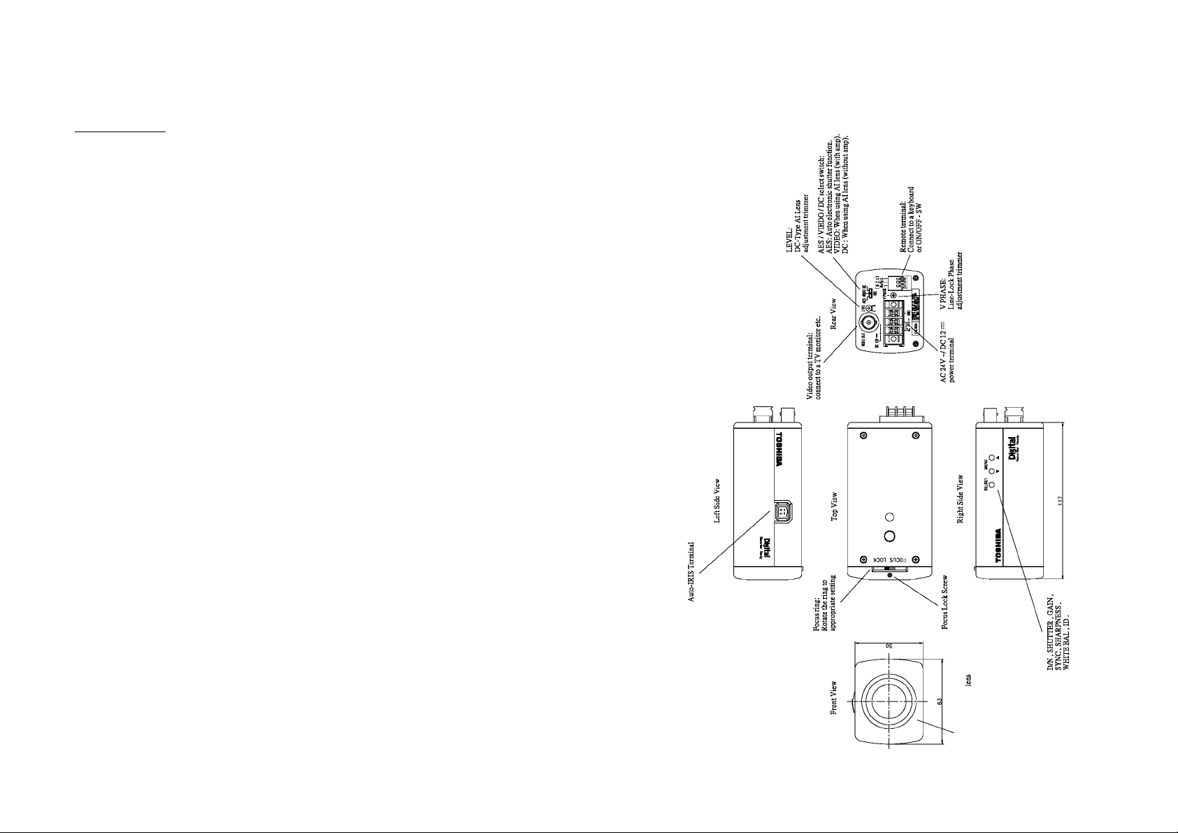
4. PART NAMES & FUNCTIONS
3. Components :
(1) Camera
(2) Accessories
(a) Lens Connector
(b) Instruction Manual 1
(c) Lens Cap
(d) Lens, coaxial cable and power cord are not supplied with the camera.
1
1 (E4-191J-100(M))
1
-3-
-4-
Page 4
5. CONNECTIONS AND OPERATIONS :
--------------------------------
• Power plugs of connected equipment must be disconnected before
installations.
• A 75-ohm coaxial cable (3C-2Vor5C-2V) is required for standard
connection.
• For details of wiring and operation of equipment to be connected, refer to
their operation manuals.
• Lenses, coaxial cables for video signals and the power cord are not supplied
with the camera.
Refer to the operations manuals of connected equipment for detailed wiring
and overall operation instructions.
5-1 Basic connection since system confiouration
\ LPfl AES VIDEO RC
^VPHASE
Notes on connecting
Video Monitor
------------------------------
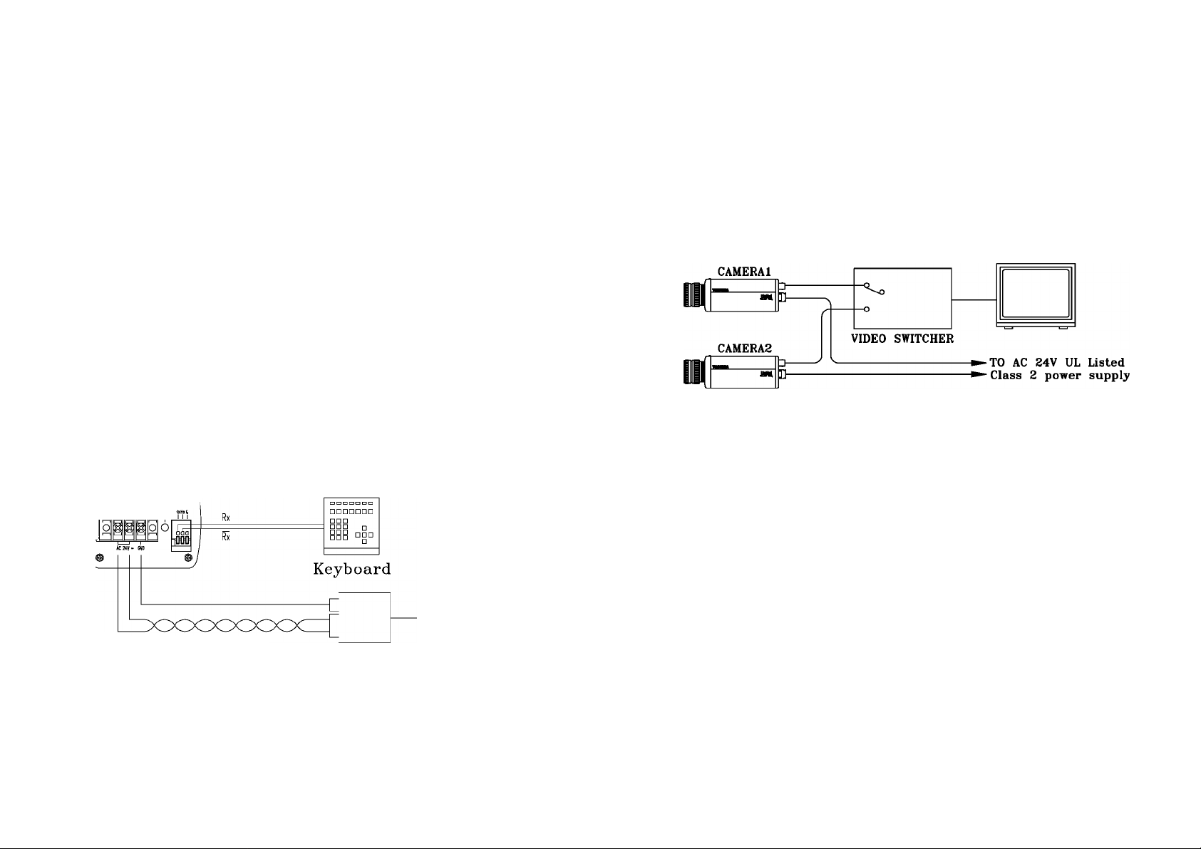
5-2 Line-Lock Control
• Matching the vertical synchronization with the power frequency is called
the Line-Lock.
• This function is activated when the SYNC menu is selected to LL.
• When two or more cameras are switched by the video switcher for viewing
by a monitor TV, the vertical sync, phase can be locked with the power
frequency, and a stable vertical sync, is obtained without being disturbed
at the time of switching.
Video Monitor
Note :
• The camera is synchronized to the power frequency of 60 ± 1 Hz covering
a normal fluctuation of the power frequency. However, the camera may not
cover a large fluctuation caused from the power generated by an engine
generator, etc.
• It takes about 10 seconds or more until a stable synchronization is obtained
after the power is turned on .This is normal, because several seconds are
required to stabilize the camera against power noise.
• Refer to "6 LINE-LOCK PHASE" for adjustment.
AC 120V
(*) POWER CORD (twisted pair line)
minimum wire size of 18 AWG is recommended.
24V AC UL Listed Class 2 power suply / 12V DC power supply
CAUTION : Never input 24V AC and 12V DC at the same time
--------------------------
Do not overload power supply
---------------------
Since this camera uses 24V AC UL Listed Class 2 power supply or 12V DC
power supply, it should be connected to a power supply that allows for at
least 15w consumption. Because the IK-64DNA uses a mechanism, a
sufficient power supply with a dequate current specifications is required.
-5-
5-3 Operation :
(1) Before mounting a lens, check whether it is a "C" mount or "CS" mount type
lens. If a "C" mount lens is used, an adapter ring is required and the back
focus will need to be adjusted.
(2) Mount the lens on the camera by turning the lens clockwise. Adjust the
diaphargm and focus for optimum image.
(3) Connect the VIDEO output to the video monitor. The picture will appear on the
monitor screen as the power is supplied to the camera.
(4) Adjust the focus and aperture of the lens for best image quality.
-6-
Page 5
6. LINE LOCK PHASE
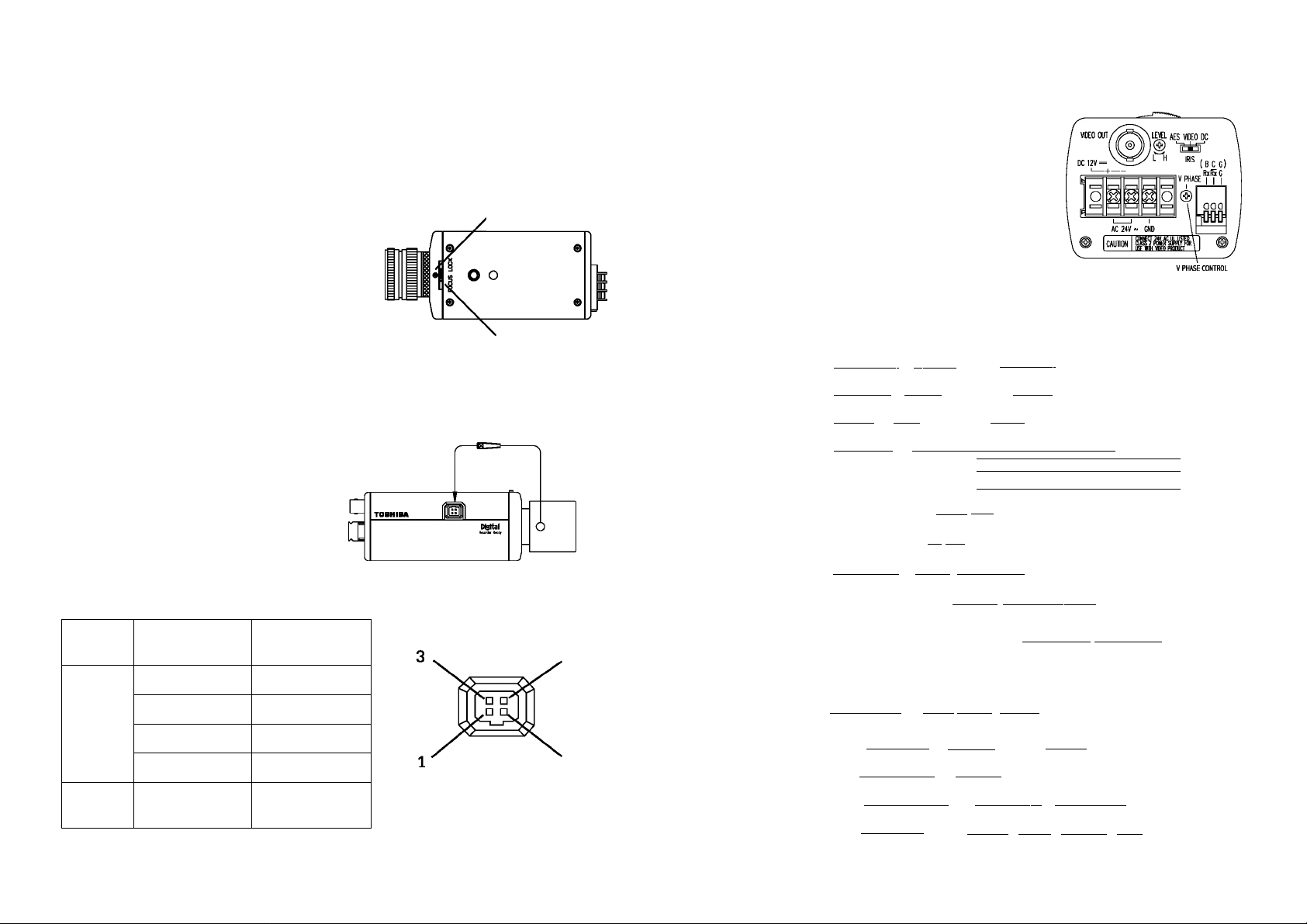
5-4 Back-Focus Adjusment
Back focus is adjusted at the factory to accommodate most standard lenses. If a
slight adjustment Is needed, mount the lens to the camera first. Then loosen the
Focus Lock Screw. Rotate the Focus ring until a clear image is achieved. Retighten
the Focus Lock Screw.
Focus Lock Screw
Note
When the lens weight is more than
1 kg (2.2 lbs), support the camera on the lens side
rather than relying on the tripod mount of the camera.
5-5 Lens
This camera supports two types of auto
-iris lens: Video-type and DC (direct drive)
types. Connect the auto-iris connector
plug to the IRIS terminal on the side of
the camera. Refer to the chart below for
correct wiring and set up.
Focus Ring
IRIS
Auto iris lens
When a video switcher switches two or more
cameras, the picture may fluctuate on the video
monitor due to the different AC line phase of
each camera. In this case, adjust the V PHASE
controller (on rear panel) to get a stable image.
7. MENU DRIVEN SET-UP
The following Is the on-screen menu structure for
all settings and adjustments of the camera.
I D/N MODE ] d) I AUTO \-------------1 MANUAL ]
I D/N level] Id) I LOW I
|D/NFIL I l=> I ON I---------------------1 OFF I
I SHUTTER ] l=> I AUTO |—| 1/60 H 1/100~|j 1/250 [-^/500 |—|
MENU
GAIN
SYNC
I SHARPNES^ III>| HIGH |—| MID HTlOW |
---------------------
I STD [-[high
|=> III [-[¡NT
1—1
1/1K
1 HIGH |
1 -1
1/2K
H
1/4K H 1/10K
I
IRIS
terminal
pin
IRIS
Switch
Video IRIS
Lens
Direct Dirve
IRIS Lens
1.-I- 12V 1. Damp-(y)
2. NC
3. VIDEO
4. GND
VIDEO
position
2. Damp+( r)
3. Driver+(wh)
4. Driver-(g)
DC
position
-7-
WHITE BAL.
ID.
—IlDPOS I l=> I OFF I 1 TOP I—I BOTTO
D/N control] d> |RS-422 |
jADDRESS I III> |001-255 j
SUB
MENU
-|pROTOcoL~| i=> |toshiba-p]—|toshiba-d~
(bitRATE 1 l=> 11200 |—12400~|—I^BOO |—19600
jsOFTVER. I m> I**" I
^ l=> I AUTO I-TÌNDOOR IT^utdoor|—j
****************
-8-
L| RGAIN:00-63|-| BGAIN:00-63|
------------
|b.C.G |
Page 6

7-1 .Setting switches and the functions
On the side panel of the cameras there are three push button switches as
shown below:
Switch name
Select
▼
A
Main function
Setting mode calls ON/OFF, setting entry
Setting item selection (down)
Setting item selection (up)
7-2 On screen MAiN menu
The camera is adjusted using the on screen menu. Press and hold the select
switch on the side of the camera body 2 seconds until the menu appears on the
monitor. The blinked area represents the option to be set.
7-2-1 D/N MODE
Set up a day/night function automatically or
manually. Move the cursor to the position in
Fig.
Use the SELECT switches to select
AUTO, MANUAL
AUTO: When set to this mode, the
camera will change to COLOR
mode and B/W mode automatically
according to a subject's brightness.
MANUAL: When set to this mode, the camera
will change to COLOR mode and
B/W mode manually according to a
RS-422 commands or simple locking
switches (B.C.G). (Refer to 7-3 On
screen SUB menu)
D/N MODE
D/N LEVEL HIGH
D/N FIL ON
SHUTTER AUTO
GAIN STD
SYNC LL
BLC OFF
SHARPNESS
WHITE BAL.
NEXT EXIT CANCEL DEFAULT
1Q ****************
IDPOS OFF
BACK EXIT CANCEL DEFAULT
CTng
HIGH
AUTO
7-2-2 D/N LEVEL
Set up a switchover point from B/W
mode to COLOR mode
Move the cursor to the position in Fig.
Use the SELECT switches to select LOW,
HIGH Under the AUTO mode, the switchover
point of brightness from COLOR mode to
B/W mode is 1.5 lx.
D/N MODE AUTO
D/N LEVEL
D/N FIL ON
SHUTTER AUTO
GAIN STD
SYNC LL
BLC
SHARPNESS HIGH
WHITE BAL. AUTO
NEXT EXIT CANCEL DEFAULT
lU.
IDPOS OFF
BACK EXIT CANCEL DEFAULT
I!lt4!l
OFF
>
J
LOW : The switchover point of brightness
from B/W mode to COLOR mode is 4.5 lx.
HIGH :The switchover point of brightness from
B/W mode to COLOR mode is 7.5 lx.
(To switch between color mode and B/W
mode within a short time, use this setup.)
7-2-3 D/N FIL = D/N FILTER
Set up a filter of CCD output in B/W
mode
Move the cursor to the position in Fig.
à
Use the SELECT switches to select
ON, OFF
ON: Y-signal filter of CCD output is
narrow in B/W mode. In this position,
the horizontal resolution is 480 TV
D/N MODE AUTO
D/N LEVEL HIGH
D/N FIL
SHUTTER AUTO
GAIN STD
SYNC
BLC
SHARPNESS HIGH
WHITE BAL. AUTO
NEXT EXIT CANCEL DEFAULT
10 ****************
IDPOS OFF
BACK EXIT CANCEL DEFAULT
s
_________________
lines.
OFF: Y-signal filter of CCD output is
wide in B/W mode. In this position,
the horizontal resolution is 570 TV
lines. (If there is horizontal noise in
B/W mode, set to ON.)
-------------------------------------^
En
LL
OFF
-9-
-10-
Page 7

7-2-4 SHUTTER
Exposure time setting in AES (MES)
position of iRiS switch on rear of the
camera
Move the cursor to the position in Fig.
Use the SELECT switches to select
AUTO,1/60, 1/100, 1/250, 1/500, 1/1K,
1/2K, 1/4K, and 1/1 OK
AUTO: Exposure time is controiied automaticaliy within a range of 1/60 sec,
to 1/100,000 sec to obtain an adequate signai.
1/60, 1/100, 1/250, 1/500, 1/1K, 1/2K, 1/4K, and 1/10K: Manuai shutter
( When an auto iris lens is used, it will display as IRIS.)
D/N MODE AUTO
D/N LEVEL HIGH
D/N FIL
SHUTTER дшд
GAIN STD
SYNC
BLC OFF
SHARPNESS
WHITE BAL.
NEXT EXIT CANCEL DEFAULT
IQ ****************
IDPOS OFF
BACK EXIT CANCEL DEFAULT
k. A
ON
LL
HIGH
AUTO
7-2-6 SYNC
\
Move the cursor to the position in Fig.
Use the SELECT switches to select INT, LL
INTThe camera is in the internal SYNC
mode.
LL: The camera is in the Line-Lock
mode. Line-Lock phase is set 0-300
degrees by adjusting the V-phase control
at the rear of the camera.
(Refer to 5.Con ections and Operations)
r
D/N MODE AUTO
D/N LEVEL HIGH
D/N FIL ON
SHUTTER AUTO
GAIN STD
SYNC
BLC
SHARPNESS
WHITE BAL.
NEXT EXIT CANCEL DEFAULT
IQ ****************
ID POS OFF
BACK EXIT CANCEL DEFAULT
!!■
OFF
HIGH
AUTO
л
7-2-5 GAIN =AGC gain setting
Move the cursor to the position in Fig.
Use the SELECT switches to select
STD, HIGH
STD: Standard position, max gain= 21 dB
HIGH:High-Sensitivity position, max gain
= 30dB
(If there is noise in low light
conditions, set to STD.
-11 -
r
D/N MODE AUTO
D/N LEVEL HIGH
D/N FIL ON
SHUTTER
GAIN
SYNC
BLC OFF
SHARPNESS
WHITE BAL.
NEXT EXIT CANCEL DEFAULT
1Q ****************
IDPOS OFF
BACK EXIT CANCEL DEFAULT
AUTO
шз
LL
HIGH
AUTO
7-2-7 BLC =Back light compensation
Move the cursor to the position in Fig.
Use the SELECT switches to select
OFF, BLC1, BLC2, BLC3, BLC4
Using in AES or auto iris lens, the
exposure adjustment is automatically
controlled so that the best picture is
obtained at next monitor zone. This
r
D/N MODE AUTO
D/N LEVEL HIGH
D/N FIL ON
SHUTTER AUTO
GAIN STD
SYNC LL
BLC
SHARPNESS HIGH
WHITE BAL. AUTO
NEXT EXIT CANCEL DEFAULT
IQ ****************
IDPOS OFF
BACK EXIT CANCEL DEFAULT
function is effective when strong light
enters and auto iris lens closes.
OFF: The camera is not BLC mode.
OFF BLCl BLC2 BLC3 BLC4
Video monitor Video monitor
ra
Video monitor Video monitor Video monitor
в
-12-
1ДЗЗ
A
H
Page 8

7-2-8 SHARPNESS
Move the cursor to the position in Fig.
Use the SELECT switches to seiect
LOW, MID, HiGH
7-2-9 WHITE BAL =White balance
Move the cursor to the position in Fig.
Use the SELECT switches to select
AUTO, INDOOR, OUTDOOR, R GAIN,
and B GAIN
AUTO: The white balance is auto
matically adjusted according
to the color temperature on
the object. The camera is
applicable to a color te
mperature range of 2500-1 OK.
INDOOR: The color temperature is fixed
at 3200K.
OUTDOOR: The color temperature is fixed at 51OOK.
R and B GAIN: Use theTA switches to adjust R Gain
(Red) and B Gain (Blue) until the desired white balance
is reached.
7-2-10 ID. =Camera ID.
Move the cursor to the position in Fig.
Use the SELECT switches to name
each camera up to 16 characters.
(FONT LIST)
0,1,2,3,4,5,6,7,8,9
A,B,C,D,E,F,G,H,l,J,K,L,M,N,0,P,Q,R,
S,T,U,V,W,X,Y,Z:,<,>,-
...
;,x,/_
r
D/N MODE AUTO
D/N LEVEL HIGH
D/N FIL ON
SHUTTER AUTO
GAIN STD
SYNC LL
BLC
SHARPNESS l!IM!l
WHITE BAL.
NEXT EXIT CANCEL DEFAULT
IQ ****************
ID POS OFF
BACK EXIT CANCEL DEFAULT
».
D/N MODE AUTO
D/N LEVEL HIGH
D/N FIL ON
SHUTTER AUTO
GAIN STD
SYNC LL
BLC OFF
SHARPNESS
WHITE BAL.
NEXT EXIT CANCEL DEFAULT
1Q ****************
ID POS OFF
BACK EXIT CANCEL DEFAULT
».
D/N MODE AUTO
D/N LEVEL HIGH
D/N FIL ON
SHUTTER
GAIN STD
SYNC
BLC
SHARPNESS HIGH
WHITE BAL. AUTO
NEXT EXIT CANCEL DEFAULT
ID POS OFF
BACK EXIT CANCEL DEFAULT
s
________________________
OFF
AUTO
HIGH
для
---------------------------
AUTO
LL
OFF
7-2-11 ID POS =Camera ID. Position
Move the cursor to the position in Fig.
Use the SELECT switches to select
OFF, TOP, and BOTTOM. Show the
Camera ID in monitor screen.
OFF: The camera ID is not displayed
TOP: The camera ID is displayed at
the top-left of the monitor
BOTTOM: The camera ID is displayed
at the bottom-left of the monitor
/
D/N MODE
D/N LEVEL HIGH
D/N FIL ON
SHUTTER AUTO
GAIN STD
SYNC LL
BLC OFF
SHARPNESS HIGH
WHITE BAL. AUTO
NEXT EXIT CANCEL DEFAULT
1n ****************
ID POS В1ЭЗ
BACK EXIT CANCEL DEFAULT
».
AUTO
>
j
7-2-12 NEXT, BACK
Move the cursor to the position in Fig.
Press the SELECT switch to select the
past page or next page.
à
r
D/N MODE AUTO
D/N LEVEL HIGH
D/N FIL ON
SHUTTER AUTO
GAIN STD
SYNC LL
BLC OFF
SHARPNESS HIGH
WHITE BAL. AUTO
ID
ID POS OFF
гдяа EXIT CANCEL DEFAULT
».
EXIT CANCEL DEFAULT
7-2-13 CANCEL
Move the cursor to the position in Fig.
'
Press the SELECT switch to exit the
menu without saving any changes.
r
D/N MODE AUTO
D/N LEVEL HIGH
D/N FIL ON
SHUTTER AUTO
GAIN STD
SYNC LL
BLC OFF
SHARPNESS HIGH
WHITE BAL.
NEXT EXIT DEFAULT
ID
ID POS OFF
BACK EXIT MJJWdl DEFAULT
».
AUTO
- 13-
- 14-
Page 9

7-2-14 EXIT
Move the cursor to the position in Fig.
Press the SELECT switch to save ali
changes and exit the menu.
7-2-15 DEFAULT
Move the cursor to the position in Fig.
Press the SELECT switch to select
DEFAULT, which returns the camera to
its factory settings.
(Defauit settings)
D/N MODE AUTO
D/N LEVEL HiGH
D/N FiL ON
SHUTTER AUTO
GAiN STD
SYNC LL
BLC OFF
SHARPNESS HiGH
WHiTE BAL AUTO
iD.
iD. POS OFF
r
D/N MODE AUTO
D/N LEVEL HIGH
D/N FIL ON
SHUTTER AUTO
GAIN STD
SYNC LL
BLC OFF
SHARPNESS HIGH
WHITE BAL. AUTO
NEXT ISH CANCEL DEFAULT
ID.
ID POS OFF
BACK I3!ni
D/N MODE
D/N LEVEL
D/N FIL
SHUTTER
GAIN
SYNC
BLC
SHARPNESS
WHITE BAL.
NEXT EXIJ CANCEL EnaBs,,,
IQ ****************
ID POS OFF
BACK EXIT CANCEL
CANCEL DEFAULT
AUTO
HIGH
ON
AUTO
STD
LL
OFF
HIGH
AUTO
7-3 On screen SUB menu (FOR REMOTE CONTROL)
The camera is adjusted using a sub menu for setup using a remote controi.
Press and hoid the A switch on the side of the camera body 2 seconds until
the menu appears on the monitor. The biinking area represents the option to
be set.
(This sub menu cannot controi from a keyboard by RS-422)
(Default settings)
D/N CONTROL RS-422
ADDRESS 001
PROTOCOL TOSHiBA-P
BiT RATE 4800
7-3-1 D/N CONTROL
Move the cursor to the position in Fig.
Use the SELECT switches to select
RS-422. B.C.G
This setup changes Coior mode and
B/W mode manualiy.
it accepts when having set D/N MODE
as MANUAL in the main menu.
RS-422: At this setup, D/N mode can be controiied by a remote controi from a
keyboard etc. by RS-422.
B.C.G: (B=B/W, C=Coior, G=GND)
At this setup, a iock type switch is only connected with the terminai of
rear of the camera and D/N mode can operate by switch settings.
Note: When using this setup, please be sure to change an internal switch.
Refer to “8.Remote control” .
D/N CONTROL ^S422^|
ADDRESS 001
PROTOCOL
BIT RATE 4800
SOFT VER.
TOSHIBA-P
He
EXIT DEFAULT
- 15-
-16-
Page 10

7-3-2 ADDRESS
Move the cursor to the position in Fig.
Use the SELECT AT switches to
select 001 to 255
7-3-3 Protocol
Move the cursor to the position in Fig.
Use the SELECT switches to seiect
TOSHiBA-P, TOSHiBA-D
D/N CONTROL RS422
ADDRESS [iliH
PROTOCOL
BIT RATE 4800
SOFT VER.
EXIT DEFAULT
D/N CONTROL RS422
ADDRESS 001
PROTOCOL
BIT RATE 4800
SOFT VER.
TOSHIBA-P
* * * *
■toshiba-p
He =1= =1=
RxRx G
2 wires
Controller
Tx of the communication line from KBD is connected to Rx of the camera, and
Tx- is connected to Rx- of the camera.
EXIT DEFAULT
7-3-4 BIT RATE
Move the cursor to the position in Fig.
Use the SELECT switches to select
1200, 2400, 4800, 9600bps
In RS-422 control, it is necessary to set
a unique camera address I and bit rate
for each camera.
D/N CONTROL RS422
ADDRESS 001
PROTOCOL
BIT RATE EEIiTil
SOFT VER.
EXIT DEFAULT
TOSHIBA-P
* * H= H=
7-3-5 SOFT VER.
Software version display
8. Remote control:
This camera supports 2-type remote control.
8-1 RS-422 Control (Factory-setting) supported TOSHIBA-P and
TOSHIBA-D
Internal switch location
Internal
A controllable function is as follows.
Preset Number Function
71 GO Backlight compensation ON (zone: BLC2)
72 GO Backlight compensation OFF
75 GO Software version display
88 GO IR cut filter ON (Color mode)
89 GO IR cut filter OFF (BA/V mode)
95 SET Enter MENU mode
- 17-
-18-
Page 11

8-2 B.C.G Control
D/N control setup of a sub menu is set to B.C.G and an internal switch is set
to the BCG side, the foliowing remote controi is possible about D/N mode.
• Never touch internai parts
Do not touch the internal parts of the camera other than the parts specified.
Otherwise, the camera may malfunction.
Terminal B
OFF (H)
OFF (H) ON (L)
ON (L)
ON (L) ON (L)
(1)
BCG
0
m
-cr^ò—o
All modes
Terminal C
OFF (H)
OFF (H)
(2)
BCG
ffl
rn
ON—B/W
OFF-AUTO
MODE
AUTO
COLOR
B/W
B/W
(3)
BCG
0
777
9. NOTE ON USE AND INSTALLATION
• Do not aim the camera at the sun
Do not aim the camera at the sun or point it at sun even if you are not
shooting.
• Do not shoot intense iight
intense iight such as a spotight may cause a bloom or smear. A vertical stripe
may appear on the screen. However, this is not a malfunction.
• Treat the camera with care
Do not drop the camera or subject it to strong shock of vibration. Otherwise,
the camera may malfunction.
• Do not spiash water on the camera
Install the camera where the camera can be kept dry. If the camera gets wet,
turn off the power and contact your dealer.
• Check the ambient temperature and humidity
Avoid using the camera where the temperature is hotter or colder than
specified. Otherwise, the quality of images may deteriorate or internal parts
may be affected. Special care is required to use the camera at high
temperature and humidity.
• Shouid you notice any troubie
If any trouble occurs while you are using the camera, turn off the power
and contact your dealer. If you continue to use the camera when there
is something wrong with it, the trouble may much worse and an
unpredictable accident may occur.
10. IN CASE OF PROBLEMS
Condition Check Points
No image • Are the camera and connected equipment turned on?
• Is the iris of the lens adjusted properly?
• Are cables connected correctly?
Unnatural color
Unusual operation
of D/N mode
Press default to return the camera to factory settings (7.2.15)
• Is the monitor TV adjusted correctly?
• Is the lighting too weak?
• Is the output of a power supply proper?
-19-
-20-
Page 12

11. SPECIFICATIONS
12. EXTERIOR VIEW
Power
AC24V 10% 60(50) Hz / DC12V 10%
Power consumption 7.5W with Al lens
Image sensor
1/3 inch high sensitive CCD
Image pickup area 4.96mm(0.195inch) horizontal x 6.0mm(0.236inch) vertical
Effective picture
768 horizontal x 494 vertical
elements
Scanning system
Scanning frequency
Synchronization
Resolution (Color)
2:1 interlace NTSC standard TV system
15.75kHz horizontal, 60Hz vertical
Line- Lock, Internal
Horizontal 480 TV lines (TYP)
Vertical 350 TV lines or more
Resolution (B/W) Horizontal 570 TV lines (TYP) (D/N FIL- OFF)
Vertical 350 TV lines or more
Minimum subject
illumination (Color)
0.1 lx (FI .2, AGC HIGH, more than
10% of image output
Minimum subject 0.003 lx (FI .2, AGC HIGH, more than
illumination (B/W)
S/N
10% of image output
50dB (AGC OFF, Weight ON)
Video output VBS 1 .OVp-p / 75 ohms. Composite
White balance AUTO (2500Kto 10,000K), MANUAL
IRIS control DC / VIDEO - Iris driver circuit built in
Auto Electric shutter ON(1/60 to 1/100,000), OFF(1/60)
Gain control Average AGC - STD(21dB), HIGH(30dB)
Backlight compensation
Lens mount
Ambient temperature
4 mode BLC function
CS mount
-IOC to +50C (14F to 122F)
Ambient humidity 90% max
Weight
500g
External dimensions 63mm(W) X 50mm(H) x 117mm(D)
Safety standard UL2044, CSA C22.2
Emission standard
FCC/A, DOC/A
a
u
IS» i-(
S'
rHoir
i®£
I s
» u
MI
w
i (
a.
a
m
X
S
■q
s
-21 -
-22-
Page 13

LIMITED WARRANTY
CCD SECURITY CAMERA
The Imaging Systems Division of Toshiba America infbrmation Systems, Inc. ("ISD") mates the following limited warranties with
regard to this CCD Camera ("ProducT). These limited vi^rranties exterxi to the Original End-User ('You[r]").
One (3) Year Limited Warranty of Labor and Parts ISD warrants that this Product will perform in accordance with specifications
for a period of one (3) year from the date of purchase by the Original End-User. During this one (3) year period, ISD will repair or
replace the Product, if It does not perfomi as vi^vranted. In order to tate advantage of this Limited Warranty. You must (a) deiver
the Product to an ISD Authorized Service Provider ("ASP'): and (b) pay all transportation and insurance charges for shipment of the
Product to the ASP. ISD reserves the right to substitute factory refurbished parts in place of those in need of repair.
Instruction Manual (Owner's Manual): Ycxj shcxjid read the Instruction Manual (Owner's Manual) thoroughly beibre operating this
Product. Before seeking warranty service, you should check the troubleshooting guide in the Instruction Manual (Owner's Manual)
and follow the instructions to correct the problem.
How to Obtain Warranty Service Step-by-step Procedures: To obtain vt^irranty service. You should:
1. Contact Toshiba at (877) 855-1349 for operation or installation assistance. (877) 855-1 FIX
2. Contact an ASP for \№irranty service with in thirty (30) days after the Product fails to comply with specificatfons.
3. Arrange for shipment of the Product to a Toshiba Authcxized Service Provider.
4. Securely pack the Product in the original carton and external shipping pack, include a letter explaining the problem with a copy of the
bill of sale or proof of purchase.
5. Prepay all transportation and insurance costs.
Questions? If you have any questions, please check our wed site at http:/A/vww.toshiba.coriVtaisisct/security/
Your Responsibilities: This Limited Warranty is subject to the following conditions:
1. You must provide the bill of sale or proof of purchase at the time that warranty service is required.
2. You must notify an ASP within theiny (30) da^ after you disccwer that the product does not perform in accordance with specifications
during the Limited Warranty period.
3. All Warranty Service of this product must be by an ISD Authorized Service Provider.
4. You must pack the Product in its original carton using the original packing material, then insert the original carton containing the
Product into another carton with additional packing materia before shipping the Product to an ASP.
DISCLAIMERS:
ALL OTHER EXPRESS OR IMPUED WARRANTIES ON THIS PRODUCT, INCLUDING THE IMPUED WARRANTIES OF
MERCHANTABIUTY AND FITNESS FOR A PARTICULAR PURPOSE, ARE HEREBY DISCLAIMED. SOME STATES DO NOT
ALLOW THE EXCLUSION OF IMPUED WARRANTIES OR LIMRATIONS ON HOW LONG AN IMPLIED WARRANTY LASTS. SO THE
ABOVE UMRATIONS MAY NOT APPLY TO YOU.
IF THIS PRODUCT IS NOT IN GOOD WORKING ORDER AS VIARRANTED ABOVE, YOUR SOLE AND EXCLUSIVE REMEDY SHALL
BE THE REPAIR OF REPLACEMENT OF THE PRODUCT. IN NO EVENT WILL ISD OR ITS PARENT COMMNY OR ANY ASP
BE LIABLE TO YOU OR ANY THIRD PARTY FOR ANY DAMAGES IN EXCESS OF THE PURCHASE PRICE OF THE PRODUCT. THIS
UMHATION APPUES TO DAMAGES OF ANY KIND, INCLUDING ANY DIRECT OR INDIRECT DAMAGES, LOST PROFfTS, LOST
SAVINGS OR OTHER SPECIAL, INCIDENTAL, EXEMPLARY OR CONSEQUENTIAL DAMAGES, WHETHER FOR BREACH OF
CONTTUVCT, TORT OR OTHERWISE, OR WHETHER ARISING OUT OF THE USE OF OR INABIUTY TO USE SUCH PRODUCT,
EVEN IF TAIS, rrS MRENT COMPANY, OR AN ASP HAS BEEN ADVISED OF THE POSSIBILfTY OF SUCH DAMAGES OR OF ANY
CLAIM BY ANY OTHER PARTY. SOME STATES DO NOT ALLOW THE EXCLUSION OR LIMRATION OF INCIDENTAL OR
CONSEQUENTIAL DAMAGES FOR SOME PRODUCTS, SO THE ABOVE UMHATINS OR EXCLUSIONS MAY NOT APPLY TO YOU.
THIS WARRANTY GIVES YOU SPECIFIC LEGAL RIGHTS, AND YOU MAY ALSO HAVE OTHER RIGHTS WHICH MAY VARY FROM
STATE TO STATE.
THIS UMfTED WARRANTY SHALL BE VOID IF THE PRODUCT OR PARTS HAVE BEEN SUBJECTED TO MISUSE, ABUSE,
ACaDENT, IMPROPER INSTALLATION, IMPROPER MAINTENANCE, OR USE IN VIOLATION OF ISO'S WRTTTEN INSTRUCTIONS,
OR WHERE THE PRODUCT HAS BEEN ALTERED OR MODIFIED WITHOUT ISO'S PRIOR AUTHORIZATION. OR UPON THE
REMOVAL OR ALTERATION OF ISO'S FACTORY SERIAL NUMBER LABOR SERVICE CHARGES FOR PRODUCT INSTALLATION,
SET UP AND ADJUSTMENT OF CONTTWLS ARE NOT COVERED BY THIS UMfTED WARRANTY.
No person, agent, distributor, dealer, authorized service provider, or company is authorized to change, modily, or extend the terms of
this Limited V\forranty in any manner whatsoever. The time within which an action must be commenced to enforce any obligation of ISD
arising under this Limited \№rranty or under any statute, or law of the United States or any state thereof, is herby limit^ to one (3) year
from the date You discovered should have discovered the problem. This limitation does not apply to implied vt^rranties arising under
state law. Some states do not permit limitation of the time within which You may bring an adion beyond the limits provided by state law,
so the above provision may not apply to You. This Limited V\terTanty gives You specific legal rights and You may also have other rights
which \^ry from state to state.
TOSHIBA AMERICA INFORMATION SYSTEMS, INC.
Imaging Systems Division
TOSHIBA
-23-
-24-
Page 14

 Loading...