

Page 1
TOSHIBA
INSTRUCTION MANUAL
CCD CAMERA
IK-542XD
For Customer Use
Enter below the Serial No.
which is located on the
bottom of the cabinet. Re
tain this information for fu
ture reference.
Model No.: IK-542XD
Serial No.:
WARNING
This is a Class A of EN55022 product. In a domestic environment this product may cause radio
interference in which case the user may be required to take adequate measures.
_________________
FCC STATEMENT
This device complies with Part 15 of FCC Rules. Operation is subjectto the following two conditions:
(1) This device may not cause harmful interference, and (2) this device must accept any inter
ference received, including interference that may cause undesired operation.
INFORMATION
This equipment has been tested and found to comply with the limits for a Class A digital device,
pursuant to Part 15 of the FCC Rules. These limits are designed to provide reasonable protection
against harmful interference when the equipment is operated in a commercial environment.
This equipment generates, uses, and can radiate radio frequency energy and, if not installed and
used in accordance with the instruction manual, may cause harmful interference to radio com
munications. Operation of this equipment in a residential area is likely to cause harmful interfer
ence in which case the user will be required to correct the interference at his own expense.
USER-INSTALLER CAUTION; Your authority to operate this FCC verified equipment could be
voided if you make changes or modifications not expressly approved by the party responsible for
compliance to Part 15 of the FCC rules.
This Class A digital apparatus complies with Canadian ICES-003.
Cet appareil numérique de la classe A est comforme à la norme NMB-003 du Canada.
Page 2

TABLE OF CONTENTS
1. COMPONENTS..........................................................................3
2. FEATURES..............................................................................3
3. SPECIFICATIONS.......................................................................4
4. NAMES AND FUNCTIONS, EXTERNAL SIZE .........................................5
4.1 Camera Head
4.2 Camera Controller
5. CONNECTION.......................................................................... 8
5.1 When Using AC Adapter.........................................................8
5.2 When Using 12 Pin Connector
6. I/O SIGNALS........................................................................... 9
6.1 External Sync Signal........................................................... 9
6.2 Trigger Input....................................................................9
6.3 12 Pin Connector DC IN/SYNC Terminal
7. ELECTRONIC SHUTTER SETTING METHOD
8. VIDEO OUTPUT IN NORMAL MODE
9. VIDEO OUTPUT IN 1-PULSE TRIGGER MODE
(For setting, refer to page 18.)
9.1 1-Pulse Trigger SYNC Reset Mode..........................................12
9.2 1-Pulse Trigger SYNC Non Reset Mode
9.3 1-Pulse Trigger TRIG ~ EXT. VD Exposure Mode..........................14
10. VIDEO OUTPUT IN 2-PULSE TRIGGER MODE
(For setting, refer to page 18.)
10.1 2-Pulse Trigger SYNC Reset Mode.........................................15
10.2 2-Pulse Trigger SYNC Non Reset Mode
11. FREEZE MODE......................................................................17
12. LOCATION AND FUNCTION OF INTERNAL SWITCHES
13. GAIN SWITCH.......................................................................18
14. CHANGING HEAD CABLE ORIENTATION.........................................22
15. CAUTIONS ON USE AND INSTALLATION.........................................24
16. BEFORE MAKING A SERVICE CALL
...................................................................
.............................................................
..................................................
..................................
.......................................
................................................
...................................................
....................................
.................................................
...................................
.........................
...............................................
5
6
8
10
11
11
12
13
15
16
17
24
Page 3

1. COMPONENTS
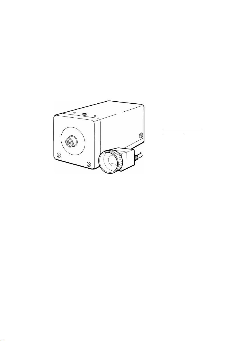
(1) Camera head................................................................................... 1
(2) Camera control unit
(3) C-mount ring................................................................................... 1
(4) Instruction manual............................................................................1
(5) Warranty card..................................................................................1
.......................................................................
2. FEATURES
Full frame shutter camera utilizing a square pixel format.
(1) Square pixel array with a VGA format (progressive scan) CCD employed.
The square pixel format and progressive scan image output make this camera well
suited for the computer environment.
(2) Frame shutter
Ability to capture entire images in one exposure. This effectively doubles the vertical
resolution of the camera.
(3) Odd/Even signals output at the same time.
Full frames can be output in 1/60 second, twice as fast as conventional cameras.
(4) Applicable to EIA standard output by memory as standard equipment.
Since the field memory is standard equipment, the unit is applicable to EIA standard
output. This allows you to use the picture processing devices and monitor, etc. that
you presently use. (The exposure Interval is 1/30 second.)
(5) 1-pulse trigger mode
With the 1-pulse trigger mode exposure can be activated by a single pulse at asyn
chronous intervals.
(6) 2-pulse trigger mode
The exposure time is determined by the width of 2 pulse with the 2-pulse trigger
mode, also this is available on a long exposure time over 1/60 second.
(7) Electrical shutter speeds
15 Shutter speeds are available allowing exposure time to be set in discrete inter
vals.
(8) Small sized camera head of 26mm(W) x 22mm(H) x 30mm(D) allows installation in a
very small space.
(9) C-mount lens
A C-mount ring is supplied so that widely available C-mount lenses may be used.
(10) Gold plated 12 pin connector
Power, outputs and inputs are available on one convenient connector to allow com
plete wiring with only one cable.
1
Page 4

3. SPECIFICATIONS
Power supply
Power consumption
Image element
Effective pixels
Effective shooting area
Scanning system
Scan frequency
Sync system
Trigger function
Resolution
Normal illumination
Min. illumination
S/N ratio
Video output
Output impedance
Lens mount
Ambient operating
temperature/humidity
Anti-vibration and shock
Weight
Camera cable
Dimensions
Gain switch
Electronic shutter
Video output switch
Applicable regulations
Others
Option accessories
DC12V±10%
4.3W
1/2 inch, interline transfer CCD
H: 659 pixels, V: 494 pixels
H: 6.52mm, V: 4.89mm (1/2" type)
2:1 interlaced, non interlaced modes
Horizontal: 15.734 kHz, Vertical: 59.94 Hz
Internal/External (automatic switching)
• HD, VD mode
1-pulse / 2-pulse trigger mode
• sync reset mode
• sync non reset mode
• TRIG ~ EXT. VD mode (Only at 1-pulse trigger mode)
H: 490 TV lines, V: more than 480 TV lines
400 lx (F4 gamma=0.45, gain SW: off)
3 lx (FI.4, gamma=0.45, gain SW: on, gain max.)
More than 56 dB (gamma=1.0. weighting filter ON)
1.0 V(p-p), based on EIA system
75 Q unbalanced
M19 (P=0.5) (C-mount conversion ring supplied)
-10 ~ ±50°C / less than 90% relative humidity
Anti-vibration 70m/s^ (10 ~ 200Hz), Anti-shock 700m/s^
Camera head: about 25g (without cable)
Camera controller: about 160g
Directly extended from head side
Length: 0.5m, Diameter: 5mm
Camera head: 26 (W) x 22 (H) x 30 (D) mm
Camera controller: 44 (W) x 44 (H) x 77.5 (D) mm
OFF (0 dB) /ON (0 ~ +9 dB) internal GAIN VR available
1/30S, 1/60S, 1/100s, 1/125s, 1/250S, 1/500s, 1/1000s,
1/1500s, 1/2000S, 1/3000S, 1/4000s, 1/6000s, 1/8000s,
1/10000s, 1/30000S, 1/50000S
1/301 output: EIA standard output (1/30s)
1/60N output: 2 lines parallel output (1/60s)
1/30N output: 1 line sequential output (1/30s)
CE, FCC Class A, VCCI Class A based
Video index output, image output (DC coupled)
Extension cable (EXC-7X01: 1.5m), (EXC-7X03: 3m)
(protrusion not included)
(protrusion not included)
Page 5
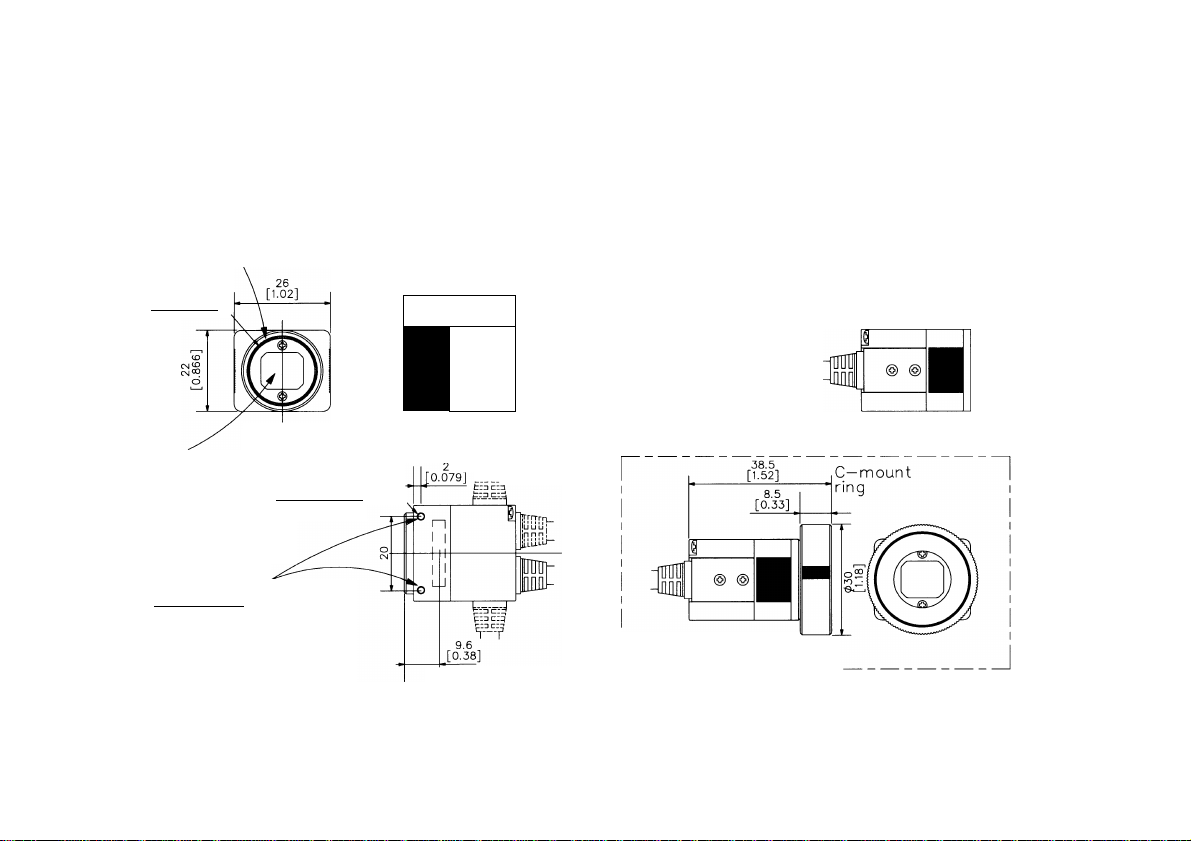
Lens mount _
M19 (pitch 0.5) special
mount lens can be used.
C—mount lens can be used
with C—mount ring supplied.
M19(pitch 0.5)
TOP
30
[1.18]
1 |50.079]
_____
Camera cable
Diameter : 5mm
Length : 0.5m
СЛЮ
Camera connector
Connect to CAMERA terminal
on camera controller.
Í
01
Dumny glass
Take care so that dust,
finger prints, etc. 2-M2(depth 5mm)^
are not applied.
Camera head securing
screw holes
Screw holes to mount
the camera head.
FRONT
___________
RIGHT SIDE
.‘ТгД
CCD Imager
(in air 9 [0.35])
BOTTOM
REAR LEET SIDE
External view with
C—mount ring installed.
L
Unit : mm [ inch ]
0 : diameter
Page 6
Page 7

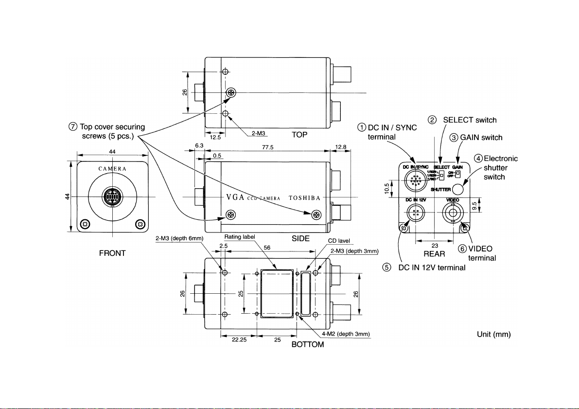
© DC IN/SYNC terminal (For detail, refer to page 10.)
Used when performing the external sync and trigger function. Also used for power supply
and video output.
SELECT switch
Switches the camera video output system.
SELECT
1/30N
1/60N
1/301
1/30 second non-interlace mode (line sequential output)
1/60 second non-interlace mode (ODD/EVEN simultaneous output)
1/30 second interlace mode (output of EIA standard.)
Video output system
GAIN switch
Switches the camera sensitivity.
GAIN
ON
OFF
Sensitivity Remarks
0-9dB
OdB
Adjustable with the volume inside the camera
controller.
Normally set to this position.
® Electronic shutter switch
Performs setting of the standard mode and shutter speed (exposure time) at 1 pulse
trigger mode, and switching into 2-pulse trigger mode.
DC IN 12V terminal
Used as a DC 12V input terminal.
VIDEO terminal
Develops video signal (VIDEO 1).
----
Important
The VIDE01 output of 7512,1 V(p-p), is obtained from either terminal of the DC IN/SYNC
or the VIDEO. The output is not developed simultaneously from both terminals.
.....
.....
@ Top cover securing screws
Remove 5 securing screws, and remove the top cover to set switches and to adjust
volume inside the camera.
Page 8
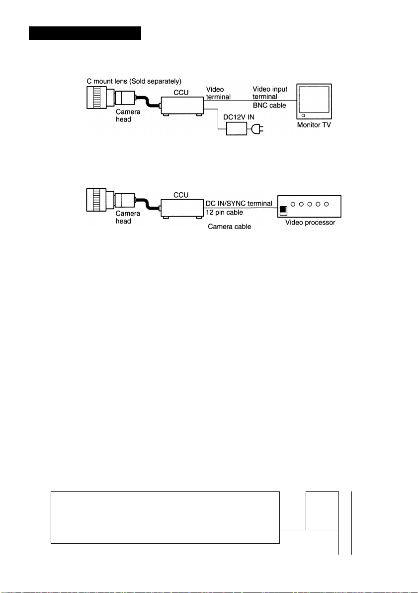
5. CONNECTION
AC adapter (Sold separately)
lillUwi iiftnii 'SS '.PIb'
C mount lens (Sold separately)
(EXC 505G, etc.)
For pin layout of 12 pin connector, see Page 10. When
making a cable, use a connector equivalent to HIROSE
DENKI connector (HR10A-10P-12S(01)).
Important:
A matching label is provided on each camera head and controller. If heads
and controllers are mismatched performance cannot be guaranteed. Always
use units with the same matching label.
For DC power (12V), an optional AC adapter AC-M412W is recommended. When using
any other power supply, make sure it meet the following specifications:
Output voltage: DC12V ±10%
Current capacity: Higher than 0.4A, less than 1.0A
Ripple voltage: Less than 50 mV (p-p)
Connector: DC input connector
(Hirose Denki HR10A-7P-4S)
Pins 1,2:©, pins 3, 4:
Applicable lens
When using a special mount lens (M19 pitch 0.5), the mounting threads or any protru
sion from the rear of the lens should be less than 4 mm in length. When using a C-
mount lens, the length should be less than 6.5 mm.
When the weight of the lens exceeds 300g,
mount the camera head by the lens.
This camera has no adjustment mechanisms for back focus.
0
Lens
1
L
—►
Page 9

6. I/O SIGNALS
1. HD 3.0 ± 1.5 V (p-p) negative polarity, 75 Q unbalanced
2. VD 3.0 ± 1.5 V (p-p) negative polarity, 75 Q unbalanced
• External sync frequency should be within ± 1% from H sync frequency.
Important:
Input pulse specifications are as follows:
1. HD 6.0 |is ~ 10.0 [IS
2. VD ЗН^^ЭН
1. Pulse level
2. Edge timing:
3. Input interface (S202)
TTL
DC IN/SYNC
Pin 11
Low level: less than 0.5V, High level: 4-5V
TTL: Rising Edge
OPT: Falling Edge
• Important
Width of the input trigger is as follows:
5 ps < trigger width < 1ms
P 560
DC IN/SYNC
Pin 11
OPT
:iok
Page 10

IS Pin PC m/9Wm WmOmai
To use the DC IN/SYNC terminal, use following connections.
DC IN/SYNC terminal
1 9
Pin
Number
1
2
3
4
5 HD input (GND)
6
7
8
9
10 VIDEO INDEX
11
12
VIDEO 1 output is obtained at VIDEO terminal or DC IN/SYNC (pin 4) terminal, and
VIDEO 2 output at DC IN/SYNC (pin 9) terminal.
In 1/301 and 1/30N modes, the video output is developed at VIDEO 1.
In 1/60N mode, the odd and even video outputs are alternately developed at VIDEO 1
and VIDEO 2.
Ext. sync mode
HD,VD
GND GND
+ 12V + 12V
VIDEO 1 (GND)
VIDEO 1 (Signal)
HD input (Signal)
VD input (Signal)
VIDEO 2 (GND)
VIDEO 2 (Signal)
TRIGGER IN
VD input (GND)
Internal Sync Mode
VIDEO 1 (GND)
VIDEO 1 (Signal)
-
-
-
VIDEO 2 (GND)
VIDEO 2 (Signal)
VIDEO INDEX
TRIGGER IN (Signal)
TRIGGER IN (GND)
- Important:-
VIDEO 1 output is developed at either terminal of the VIDEO or the DC IN/SYNC.
In 1/301 and 1/30N modes, the VIDEO 2 output is not used as a video signal output.
10
Page 11

7. ELECTRONIC SHUTTER SETTING METHOD
The electronic shutter switch number is corresponds to the shutter speeds shown in the
table below.
Switch
Position
Shutter speed
Position (sec)
Switch
Position
Shutter speed
Position (sec)
* In 1/30 second shutter speed, set the switch position to "0" and turn S201® "ON". (Avail
able only when developing in 1/301, normal mode.)
Note 1:
• The position "F" is set at 2-pulse trigger.
0
1 1 1
60
8 9
1 1 1 1 1 1
3000 4000
1
100 125 250 500 1000 1500
2
A B
6000 8000 10000 30000
3
1 1 1 1 1
4
C
5 6
D E
1
50000
8. VIDEO OUTPUT IN NORMAL
Normal mode
Exposure
• 1/301
VIDEO 1
• 1/60N
VIDEO 1
1
u
1
u U U
1
u
1 1 AODD 1 1 A EVEN 1
U U
1 1 AODD 1
1 1 A EVEN 1 1 BODD 1
~LI LI
1 B EVEN 1 1 C ODD 1 1 D EVEN I
1 CODD 1 1 C EVEN 1
r LI 1
u
1 Ij I
h
1 C EVEN 1 1 DODD 1
L1 L 1
7
2000
F
(Note 1)
• 1/30N 1 1 X+Ai1.2
VIDEO 1 II II 1
* In 1/301 and 1/30N modes, the VIDEO terminal or pin 4 (VIDE01) of DC IN/SYNC terminal
can develop the VIDE01 output. (Simultaneous output by using both terminals is not al
lowed.)
* In 1/60N mode, the VIDEO terminal or pin 4 (VIDE01) of DC IN/SYNC terminal can develop
the VIDE01 output. Pin 9 of DC IN/SYNC develops VIDE02 output.
................
) 1
1 B+Ci1.2
................
) 1
11
Page 12

9. VIDEO OUTPUT IN 1 -PULSE TRIGGER MODE
(For setting, refer to page 18.)
This mode outputs one frame video image at arbitrary timing.
A SYNC reset mode which is reset by a V sync trigger, SYNC non reset mode which does
not reset, and a TRIG-EXT. VD mode which allows arbitrary exposure time setting are
provided.
>»11 -PiihNi TIrtiBier imc Reartl lleie
In this mode, the exposure begins with the trigger pulse, the exposure is carried out for
the time set by the shutter speed, and the V sync is reset upon completion of the expo
sure. (Trigger polarity in TTL mode)
I— Sync input conditions:—I
Int. sync: available
1/301 mode (SELECT SW: 1/301)
Trigger
pulse
Exp osure
Vlideo
output
VIDEO 1
VIDEO
INDEX
time
i/ 'if
EVE N
Ext. sync: HD yes
VD no
12
1/60N mode (SELECT SW: 1/60N)
Trigger
pulse
Exp osure
Vlideo
output
VIDEO 1
VIDEO 2
VIDEO
INDEX
1/30N mode (SELECT SW: 1/30N)
Trigger
pulse
Vlideo
output
VIDEO 1
VIDEO
INDEX
time
Exp osure
time
ODD
EVE N
if
Page 13

In this mode, the exposure begins with the trigger pulse, the exposure is carried out for
the time set by the shutter speed, the video signal is output at the first V sync after comple
tion of the exposure (Trigger polarity in TTL mode).
— Sync input conditions: -
Int. sync: available
Ext. sync; HD yes
VD yes
1/301 mode (SELECT SW: 1/301)
Trigger
pulse
Video
output
VIDEO 1
VIDEO
INDEX
1/60N mode (SELECT SW: 1/60N)
Trigger fl
pulse
_______
Video
output
VIDEO 1
Exp osure
time
I L
Exp osure
1T
time
u*
\s
V V
u u
- 1.5 H
u
1
VIDEO 2
VIDEO
INDEX
IT
1
]
u
"1
_______
u
1/30N mode (SELECT SW: 1/30N)
Trigger
pulse
Video
output -I r
VIDE01 ^
VIDEO
INDEX
Exp osure
time
V
13
Page 14

' 1|
In this mode, the exposure begins with the trigger pulse, and the exposure completes at trail
ing edge of the external sync VD input. The video signal is output at first V sync after comple
tion of the exposure (Trigger polarity in TTL mode).
— Sync input conditions: —
Int. sync: unavailable
Ext. sync: HD yes
1/301 (SELECT SW: 1/301)
Trigger
pulse
EXT. VD
Video
output
VIDEO 1
1/60N mode (SELECT SW: 1/60N)
u
Exp osure
time
U U U If
u* y \\
----------
VD yes
If
14
Trigger
pulse
EXT. VD
Video
output
VIDEO 1
VIDEO 2
1/30N mode (SELECT SW: 1/30N)
Trigger
pulse
EXT. VD
Video
output
VIDEO 1
_____[1____
If
If
11
u u IJ
Exp osure
time
II
Exp osure
U~—If
■y \r
time
u u
1 1
If
IT
Page 15

1 O. VIDEO OUTPUT IN 2-PULSE TRIGGER MODE
(For setting, refer to page 1 8.)
This mode outputs one frame video image at arbitrary timing. The exposure time is determined
by the width of 2 pulses.
A SYNC reset mode which is reset by a V sync trigger, and SYNC non reset mode which
does not reset are provided.
In this mode, the exposure begins with the trigger pulse, and ends with the next trigger
pulse. At this time, the V sync is reset upon completion of the exposure. (Trigger polarity
in TTL mode)
Sync input conditions: —I
Int. sync: available
Ext. sync: HD yes
1/301 mode (SELECT SW: 1/301)
VD no
Trigger
pulse
Video
output
VIDE01
VIDEO
INDEX
1/60N mode (SELECT SW: 1/60N)
Trigger
pulse
Video
output
VIDEO 1
VIDEO 2
VIDEO
INDEX
1/30N mode (SELECT SW: 1/30N)
Trigger
pulse
Video
output
VIDEO 1
J1
__
Exp osure
time
J1
__
Exp osure
time
ji
_______
Exp osure
time
fl
U* ‘if
fl
if
a.
EVE N
ODD
EVE N
VIDEO
INDEX
15
Page 16

.m
.....
IkiiiiiliiliO MfiU! m m ^ J k ^
ákm^wr^InKm^m eire*HB|lF» HPH »w^ IWIB WMPi^HrB BWMPBHHP
In this mode, the exposure begins with the trigger pulse, and ends with the next trigger
pulse. And, the video signal is developed at the first V sync after completion of the expo
sure (Trigger polarity in TTL mode).
— Sync input conditions: -
Int. sync: available
Ext. sync: HD yes
1/301 mode (SELECT SW: 1/301)
VD yes
Trigger
pulse
Video
output
VIDEO 1
VIDEO
INDEX
1/60N mode (SELECT SW: 1/60N)
Trigger
pulse
Video
output
VIDEO 1
VIDEO 2
VIDEO
INDEX
1/30N mode (SELECT SW: 1/30N)
Trigger
pulse
Video
output
VIDEO 1
T
_ _ _
Exp osure
time
IT
J1
______
Exp osure
time
--U--U IJ
________
J1
______
Exp osure
time
If
fl
li V—V
I
n_
u
—1
J—
1—
n_
if
U
---
IT“
u u
1_______
V
-1.5H
“U
u
16
VIDEO
INDEX
Page 17

1 1. FREEZE MODE
When the video signal output is developed in 1/301, 1-field still image is obtained with the
freeze switch (S20l(D) "ON" in 1-pulse trigger SYNC non reset mode or 2-pulse trigger SYNC
non reset mode.
Trigger П
pulse
_______
I L
Video
output
VIDEO 1
VIDEO
INDEX
Exp osure
time
"U—
1 г
11
-1.5H
1 2. LOCATION AND FUNCTION OF INTERNAL
SWITCHES
Location diagram of the CCU internal switches
Name
S201®~®
5201®
S201®
S202
S101 Gamma correction switch
Note 1: This is available only when the video signal is developed in 1/301 of either 1-
pulse trigger SYNC non reset mode or 2-pulse trigger SYNC non reset mode.
Note 2: This is available only when the video signal is developed In 1/301 of the normal
mode with the electrical shutter switch set to "0".
- Important:
When changing the switch setting, always turn off the power, and use an insulated
screw driver, etc.
Function
1-pulse / 2-pulse trigger
mode setting
Freeze (Note 1)
Low speed (1/30 second)
shutter (Note 2)
Trigger input
impedance switch
Location
Refer to the Table 1.
ON
ON
TTL
OPT
1.0
0.45
17
Page 18

Table 1 Normal mode and trigger mode switch position
ON
S201
©
OFF
S201
@
ON ON
S201
OFF
OFF OFF ON
OFF ON ON
OFF OFF ON
OFF ON ON
1 3. GAIN SWITCH
GAIN SW
OFF
ON
@
OFF
S201
®
OFF 0~E
ON 0~E
ON 0~E
ON E
ON F
ON F
Electronic
shutter SW
GAIN
OdB
0'^+9dB
Operation description
Normal mode
1-pulse trigger SYNC non
reset mode
1-pulse trigger SYNC reset
mode
1-pulse trigger TRIG ~ EXT.
VD mode
2-pulse trigger SYNC non
reset mode
2-pulse trigger SYNC reset
mode
Remark
Adjustable by using the volume (RV15)
inside the CCU.
18
Location diagram of the CCU internal GAIN volume (RV15)
Important
When turning the volume, always use an insulated screwdriver, etc.
Page 19

Figure 1 Output waveform timing chart (H)
(D
Page 20

N)
O
Figure 2-1 1/60N and 1/301 output waveform timing chart
(V)
EVEN field
42.4 ^s-
OO O CM -«t I
CO O) o> O) I
11
^ Blank transfer
Optical black
I
20
V blanking period
Optical
black
J^l
J3
|T-coinr~a)i-i-i-
252
247
Effective pixels
EVEN image
ODD image
242.5
Effective video period
Page 21

Figure 2-2 1/30N output waveform timing chart (V)
F1
HD
VD
FSG
CBLK
CCD
OUT1
2^
It- CM CO
Icj) CD O)
1
ODD field
.....
...............................
1
Optical black
V blanking period
42.4 |is
24
Blank transfer
33
...........
.
.................
n 4
Optical
black
t~ oico '«■ (o eft
...........
M i l l
504
494
Effective pixels
CM CO -5J- in CD
492
Effective video period
IS)
Page 22

14. CHANGING HEAD CABLE ORIENTATION
The output direction of the camera cable on the camera head can be changed from left
back (factory setting viewed in front of) to left side. Changing the output direction will
change wiring conditions inside the camera head, so be careful. Changing to right back or
right side is also possible, but consult with the service shop or service personnel in this
case.
(A) Output direction changing from left back to left side
Changing from left
back to left side
Pull out in left back direction
Procedures
1
T
1 Æ
t2
Pull out in left side direction
(D
i ili
h
Note:
Take care not to apply tension and torque to the wiring material inside the camera
head and the flexible PC board, it may cause break down of the wiring leads or dam
age the camera head.
^ H 4
Description on
procedures
1. Remove 2 screws (1 at
back side, 1 at front side)
2. Pull out cable bushing in
side direction (take care
not to damage internal
wiring leads).
3. Insert cable bushing from
back side (take care not
to jam the cable).
4. Tighten the screws firmly.
22
Page 23

Consult with the service shop or authorized personnel
The following will change wiring conditions inside the camera head. We recommend
you to use the service shop or authorized service personnel.
(B) Changing from left side to right side
Changing from left side
to right side
Procedures
Description on
procedures
1. Remove 2 securing
screws on the back panel.
Turn to right with 180°
2. Pull out flexible PC board
from back panel, and
From left side @
rotate entire back panel
by 180° in clockwise
direction (take care not to
To right side®
break wiring leads).
3. Restore flexible PC board
on back panel again and
firmly tighten 2 screws.
Cautions:
• Take care not to apply tension and torque exceeding 180° to the wiring material,
because this may change wiring conditions inside the unit. Also take care not to
twist the flexible PC board. If twisted, it may cause break down of wiring leads or
damage circuits inside the camera head
• (A) and (B) will be made in combination as required.
23
Page 24

1 5. CAUTIONS ON USE AND INSTALLATION
Carefully handle the units.
Do not drop or give a strong shock or vibra
tion to the camera. This may cause problems.
Treat the camera cables carefully to prevent
cable problems such as cable breakdown and
loosened connections.
Do not shoot intense light.
If there is an intense light at a location on the
screen such as a spot light, blooming and
smearing may occur.
Do not aim the camera at the sun. If an in
tense light enters, vertical stripes may appear
on the screen.
Lens treatment.
Do not look at the sun through the lens.
Handling of the camera head and pro
tection cover.
Keep the camera head and the protection
cover away from children. Children may put
them into mouth or swallow them acciden
tally. The protection cover protects the im
age sensing plane when the lens is removed
from the camera head, do not throw away.
Do not touch internal parts.
Tampering with the internal parts may cause
operation failure or injury.
Operating ambient temperature and hu
midity.
Do not use the camera in places where tem
perature and humidity exceed the specifica
tions. Picture quality will degrade and inter
nal parts may be damaged.
• Do not splash water.
Install the camera in a location free from
water splash. If splashed, turn off the cam
era power switch and stop supplying power,
then consult with your dealer.
• Install the camera in a location free from
noise.
If the camera or the cables are located near
power utility lines or a TV, etc. undesirable
noise may appear on the screen. In such a
case, try to change the location of the cam
era or the cable wiring.
• When not using the camera for a long
time.
Turn off the camera power switch and stop
supplying power.
• Should you notice any trouble.
If an abnormality occurs such as no picture
obtained, turn the camera power switch off
and stop supplying power, then consult with
the dealer. Using the camera without check
ing the cause of the trouble may lead to fur
ther damage or unexpected accident.
• When cleaning the camera
Always turn off the power and make a clean
ing with a piece of dry cloth. If necessary,
gently wipe with a cloth dampened with
thinned detergent. Do not use benzine, alco
hol, thinner, etc. If used, coating and printed
letters may be discolored. When cleaning the
lens, use a lens cleaning paper, etc.
1 6. BEFORE MAKING A SERVICE CALL
Symptom Items to be checked
No picture
Poor color
No external sync.
24
• Is the power supplied correctly?
• Is the lens iris adjusted correctly?
• Are the cables connected correctly?
• Is the monitor (TV) adjusted correctly?
• Is the mode switch set correctly?
• No picture is displayed with no trigger input in 1 pulse
trigger / 2 pulse trigger modes.
• Is the lens iris set correctly?
• Is the shutter speed set correctly?
Or, is the video signal developed from both terminals of
VIDEO and DC IN/SYNC? (The video signal should be
developed from either of terminal.))
• Is the mode switch set correctly?
• Is the external sync pulse entered with correct phase and
amplitude?
• Is the external input pulse entered in the accuracy within the
frequency pull-in range?
 Loading...