

Page 1
CCD CAMERA
IK-53N/IK-52N
OPERATING GUIDE
FCC Statement
This device complies with Part 15 of the FCC Rules. Operation is subject to the following two
conditions: (1) This device may not cause harmful interference, and (2) this device must accept any interference received, including interference that may cause undesired operation.
INFORMATION
This equipment has been tested and found to comply with the limits for a Class A digital device,
pursuant to Part 15 of the FCC Rules. These limits are designed to provide reasonable protection
against harmful interference when the equipment is operated in a commercial environment.
This equipment generates, uses, and can radiate radio frequency energy and, if not installed
and used in accordance with the instruction manual, may cause harmful interference to radio
communications. Operation of this equipment in a residential area is likely to cause harmful
interference in which case the user will be required to correct the interference at his own expense.
USER-INSTALLER CAUTION: Your authority to operate this FCC verified equipment could be
voided if you make changes or modifications not expressly approved by the party responsible for
compliance to Part 15 of the FCC rules.
This Class A digital apparatus complies with Canadian ICES-003.
Cet appareil numérique de la classe A est comforme à la norme NMB-003 du Canada.
Page 2

CONTENTS
1. GENERAL ....................................................................................................................2
2. CAMERA PARTS AND FUNCTIONS......................................................................... 3
3. CONNECTIONS ......................................................................................................... 5
4. SETTING .....................................................................................................................6
4-1. Field accumulation/Frame accumulation .........................................................6
4-2. Electronic Shutter ...............................................................................................7
4-3. Reset Restart ...................................................................................................... 8
4-4. External Trigger Mode ........................................................................................9
5. Input Output Signal Specifications ....................................................................... 14
6. CCD Output Waveform Timing Chart ................................................................... 16
7. EXTERIOR VIEW ...................................................................................................... 18
8. SPECIFICATIONS ..................................................................................................... 19
1
Page 3

1. GENERAL
The IK-53N/IK-52N is a monochrome video camera using a solid image sensor CCD (Charged
Coupled Device).
High Picture Quality
The 410,000 pixels CCD provides a fine picture.
Various Modes Setting
The following modes can be set by the switches on the rear panel.
• Gain: Fixed/manual adjustment (0 to +18 dB)
• Field accumulation/Frame accumulation
• Synchronized input/output (HD/VD)
• 75Ω terminal (at external synchronous input)
• Shutter function: Normal/external trigger shutter
• Shutter speed
External Synchronization
External HD/VD signals are analyzed and the synchronization mode is automatically selected
to match the input signals.
Internal Synchronizing Signal Output
HD and VD signals can be outputted from the 12-pin connector by changing the switch position on the rear panel.
Electric Shutter Speed
A variety of shutter speeds (1/100 to 1/100,000 sec) is provided to permit choice suitable for
shooting conditions.
External Trigger Function
A trigger input provides one still image. This function exactly captures a subject moving at a
high speed.
Cabinet Fixing
The cabinet fixing screw hole is provided below the front panel which includes the CCD datum
level. Fix the camera using this screw hole to minimize shifts in the optical axis.
2
Page 4
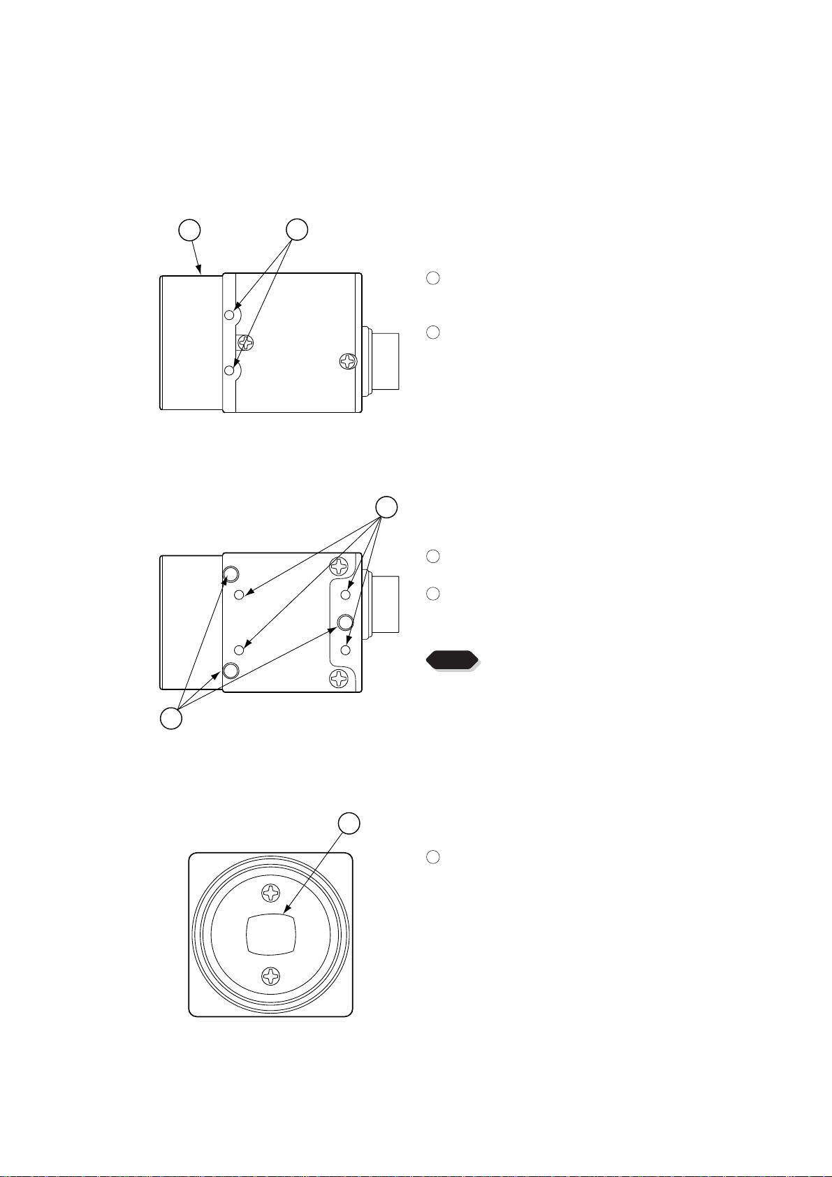
2. CAMERA PARTS AND FUNCTIONS
Top/Bottom/Front Side
1
[Top]
2
1
Lens mount (C mount)
This is used to mount a C-mount type lens or
optical equipment.
2
Camera fixing reference hole (top side)
3
3
Camera fixing reference hole/T ripod fixing metal
screw hole (bottom side)
4
Camera fixing reference hole/T ripod fixing metal
screw hole (bottom side)
NOTE
When the mass of lens exceeds 300g, fix the cam-
4
[Bottom]
5
[Front]
era at the side of the lens.
5
Imaging area
The protection cap is attached on the lens mount
portion. After removing the cap, mount the lens.
Be careful not to scratch or touch the optical
area.
3
Page 5
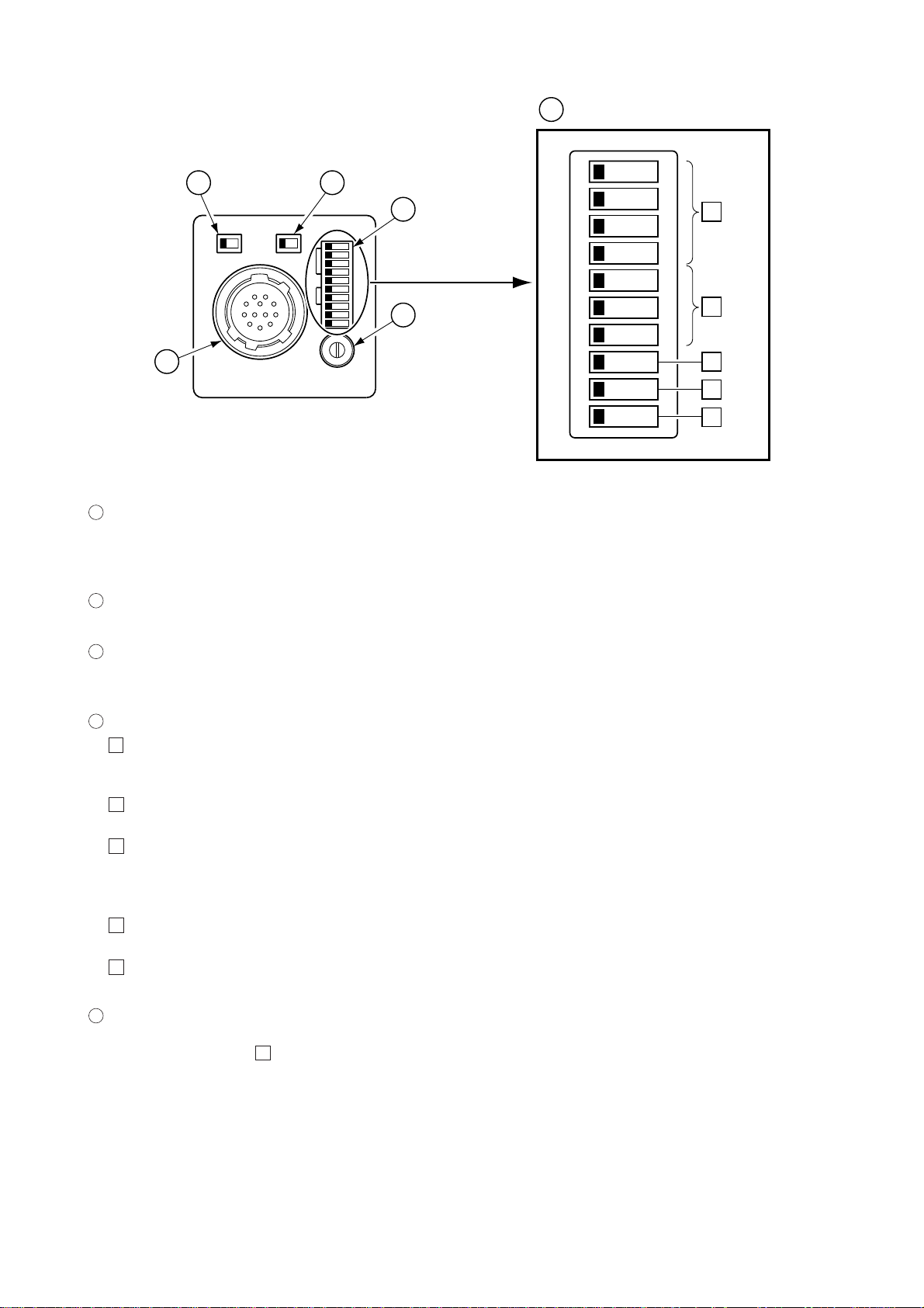
Rear Side
4
23
SHT
TRG
FRM
M.G
4
Enlarged
5
75Ω
ON OFF
EXT
HD/VD
INT
1
2
3
4
5
6
O
N
1
2
7
1
1
VIDEO OUT DC IN/SYNC plug (12-pin connector)
VIDEO OUT
DC IN/SYNC
This receives +12 VDC, and sends a video signal from the camera. When a synchronizing signal
generator is connected to this plug and an external synchronizing signal (HD/VD signal) is applied,
the camera can be operated synchronously with the external signal.
2
75Ω terminal switch (Terminal of external synchronizing HD/VD input signal)
Set this switch to OFF when not terminated. The factory setting is ON.
MIN MAX
M GAIN
8
9
0
3
4
5
3
HD/VD signal input/output selector switch
Set to INT to output the HD/VD signals from the camera, and EXT to input external HD/VD signals.
The factory setting is EXT.
4
MODE SELECT switch
1
Shutter speed setting (MODE SELECT switch bit 1 to 4)
Set to the shutter speed suitable for the shooting conditions. For each setting position, refer to
P. 7. The factory setting position is shutter OFF.
2
Reset restart/External trigger mode setting (MODE SELECT switch bit 5 to 7)
For each setting position, refer to P. 8 to 13. The factory setting position is NORMAL.
3
Trigger polarity setting (MODE SELECT switch bit 8)
Selects the polarity of an externally inputted trigger.
OFF: Positive ON: Negative
The factory setting position is OFF.
4
Field accumulation/Frame accumulation setting (MODE SELECT switch bit 9)
For the mode setting, refer to P. 6. The factory setting position is Field accumulation.
5
Gain selector switch setting (MODE SELECT switch bit 0)
This switch selects the modes OFF (fixed) or ON (manual). The factory setting is OFF (fixed).
5
Manual gain (M GAIN) control knob
This adjusts the gain of a video signal when the gain mode is set to ON by the MODE SELECT
switch bit 0 on step 5. The factory setting is the fully counterclockwise position.
4
Page 6
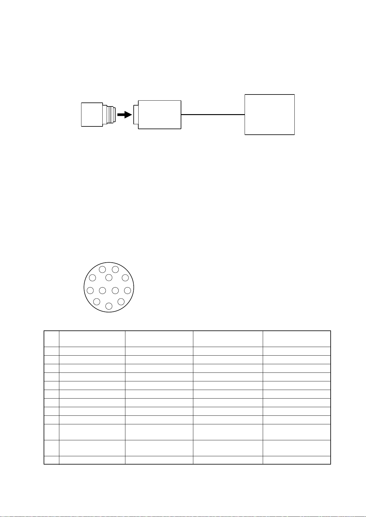
3. CONNECTIONS
Standard Connection
Lens
IK-53N
IK-52N
Cautions on Connection
• When connecting the camera cables, be sure to turn off the camera and the other equipment
connected.
• When using another lens, the best camera performance of this camera may not be obtained.
(For example, low resolution may occur, and flare, ghost or shading may occur)
• Use the DC power source described below.
• Power supply voltage: +10.5V to +15V
• Current rating: More than 830 mA
• Ripple voltage: Less than 50 mV(p–p)
Image processor
Camera Cable
(optional)
Connector Pin Assignments
1
9
10
3
Pin
External synchroniza-
No.
tion mode (HD/VD)
1
GND
2
DC+12V
3
Video output (GND)
4
Video output (signal)
5
HD input (GND)
6
HD input (signal)
7
VD input (signal)
8
GND
9
10
11
12
VD input (GND)
2
11 12
4
–
–
–
8
7
6
5
GND
DC+12V
Video output (GND)
Video output (signal)
HD input (GND)
HD input (signal)
Reset (signal)
GND
VIDEO INDEX output
(signal)
Reset (GND)
Connector:
HR10A–10R–12PB by HIROSE electronics Co. Ltd
Reset restart
–
–
External trigger mode
GND
DC+12V
Video output (GND)
Video output (signal)
HD input (GND)
HD input (signal)
VD input (signal)
GND
–
VIDEO INDEX output
(signal)
Trigger pulse input
(signal)
VD input (GND)
Internal synchroniza-
tion output signal
GND
DC+12V
Video output (GND)
Video output (signal)
HD output (GND)
HD output (signal)
VD output (signal)
GND
–
–
–
VD output (GND)
5
Page 7
4. SETTING
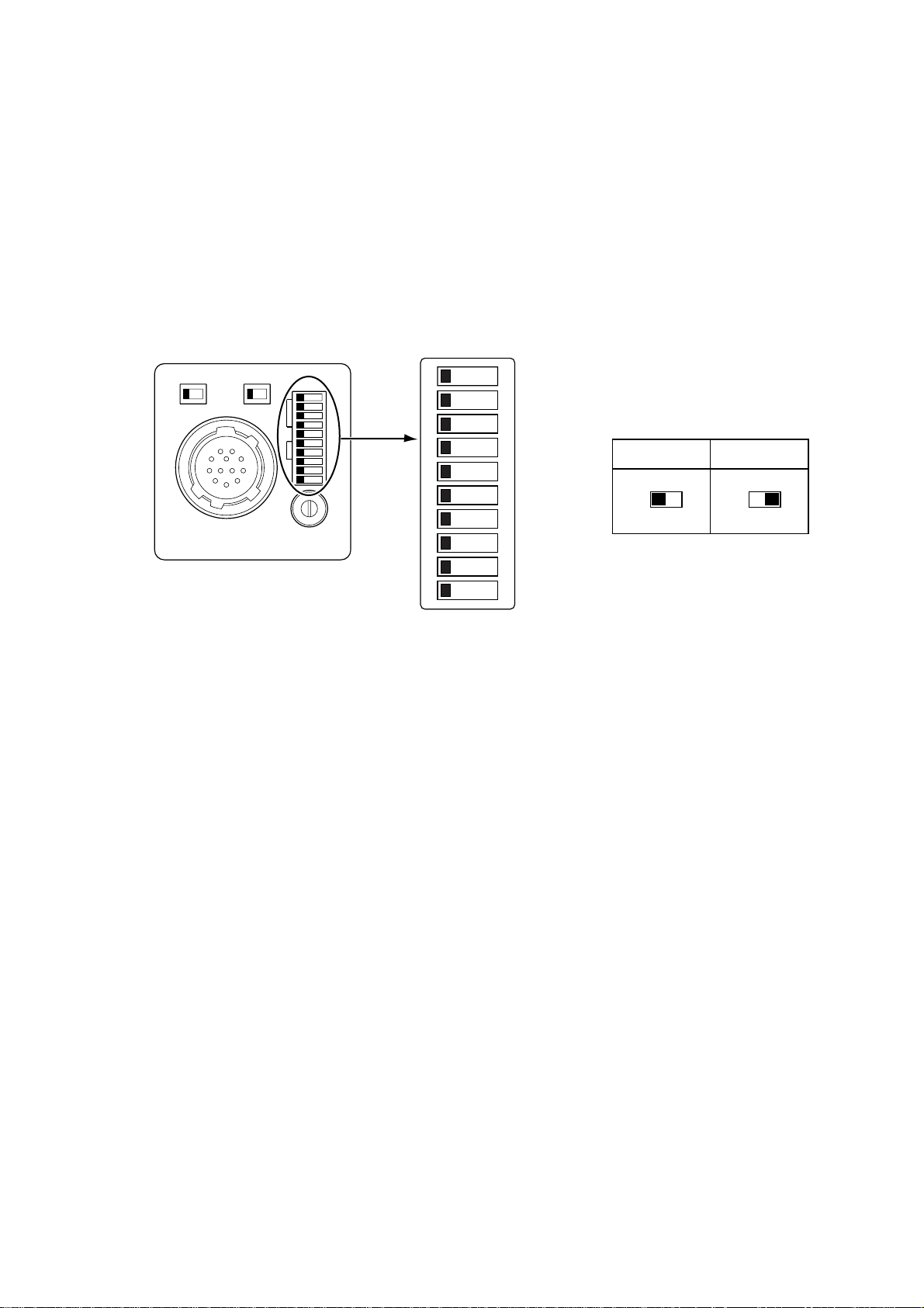
4-1. Field accumulation/Frame accumulation
This switch selects the potential accumulation mode of the CCD output signal. The mode can
be set with the MODE SELECT switch bit 9 on the rear panel.
75Ω
ON OFF
VIDEO OUT
DC IN/SYNC
Rear
HD/VD
EXT
INT
MIN MAX
M GAIN
SHT
TRG
FRM
M.G
MODE SELECT Switch
1
2
3
4
5
6
7
8
9
0
O
N
Field accumulation
9 9
Frame accumulation
6
Page 8

4-2. Electronic Shutter
This can be set with the MODE SELECT switch located on the rear panel.
Description of the MODE SELECT Switch
Rear MODE SELECT Switch
EXT
HD/VD
INT
SHT
TRG
FRM
M.G
1
2
3
4
5
75Ω
ON OFF
6
VIDEO OUT
DC IN/SYNC
MIN MAX
M GAIN
7
8
9
0
*The electronic shutter cannot be used in the reset-restart operation.
Bits 1 to 4 : Shutter speed selection*
O
Bits 5 to 7 : External trigger mode selection
N
Bit 8 : Trigger polarity selection (Positive/Negative)
Bit 9 : Field accumulation/Frame accumulation
Bit 0 : Gain selection (OFF/ON)
Normal Shutter
This mode permits a high-speed moving subject to be captured clearly with a shutter function
incorporating a continuously available video signal. Set bit 5 of the MODE SELECT switch to
OFF (i.e., the left side) as illustrated in the table below.
Normal
shutter
5
OFF
1
2
3
4
5
6
7
8
9
0
1/4000
1
2
3
4
5
6
7
8
9
0
1/10000
Reset restart
external trigger mode
or
5
1/100
1
2
3
4
5
6
7
8
9
0
1
2
3
4
5
6
7
8
9
0
1/250
1
2
3
4
5
6
7
8
9
0
1/50000
1
2
3
4
5
6
7
8
9
0
1/500
1
2
3
4
5
6
7
8
9
0
1/100000
1
2
3
4
5
6
7
8
9
0
1/1000
1
2
3
4
5
6
7
8
9
0
(unit:second)
1/2000
1
2
3
4
5
6
7
8
9
0
7
Page 9

4-3. Reset Restart
Input of an external reset-restart signal (VD) permits one screen of information to be output at
an arbitrary timing. T o set this mode, set the external trigger mode selection switch (i.e., MODE
SELECT switch bits 5, 6, and 7) as illustrated in the diagram below.
MODE SELECT Switch
1
2
O
N
3
4
5
6
7
8
Reset restart
5
6
7
75Ω
ON OFF
VIDEO OUT
DC IN/SYNC
Rear
HD/VD
EXT
INT
SHT
TRG
FRM
M.G
MIN MAX
M GAIN
9
0
Long Term Exposure
When the camera is used and sufficient sensitivity cannot be obtained for the reset-restart
function under normal operating conditions, or when observation of the trail of a moving
subject is desired, the exposure time can be extended to allow high-sensitivity images to be
obtained. To achieve this, please input from an external source a VD signal that has an expanded VD pulse and VD pulse interval.
Input Timing Chart Example
External HD
External VD
(Internal VD)
VIDEO OUT
VIDEO INDEX
IN
IN
V reset
About 1H
Exposure period
V reset
About 1H
Exposure period Exposure period
1V 1V
External VD interval: more than 1V
8
Page 10

4-4. External Trigger Mode
NOTE
Input of an external trigger permits a high-speed moving object to be captured at the proper
position. Set the rear panel external trigger mode selection switch (i.e., MODE SELECT switch
bits 5, 6, and 7) as illustrated in the diagram below.
MODE SELECT Switch
1
2
O
N
3
4
5
SYNC-NONRESET SYNC-RESET
5
6
7
5
6
7
75Ω
ON OFF
REAR
HD/VD
EXT
INT
SHT
TRG
FRM
M.G
6
VIDEO OUT
DC IN/SYNC
MIN MAX
M GAIN
7
8
9
0
In the external trigger mode, the
camera is automatically set to Field
accumulation regardless of the
MODE SELECT switch bit 9 position.
The following two modes are available for video timing.
• SYNC-NON RESET Mode
In this mode, the video is synchronized to VD after the trigger input.
When external HD*/VD is input: Sync is to external VD
When external HD*/VD is not input: Sync is to internal VD
*There is automatic determination of external sync or internal sync by the presence or
absence of external HD input.
• SYNC-RESET Mode
In this mode, reset is applied to the internal VD and the video is output after a fixed period
following the trigger pulse.
External Trigger Shutter Speed Setting
The following two methods are available for shutter speed setting.
1 pulse trigger mode␣ (Setting by the MODE SELECT switch of the rear panel)
•
For shutter speed, refer to the table below.
(unit:second)
1/100
1
2
3
4
5
6
7
8
9
0
1/4000
1
2
3
4
5
6
7
8
9
0
1/250
1
2
3
4
5
6
7
8
9
0
1/10000
1
2
3
4
5
6
7
8
9
0
1/500
1
2
3
4
5
6
7
8
9
0
1/50000
1
2
3
4
5
6
7
8
9
0
1/1000
1
2
3
4
5
6
7
8
9
0
1/100000
1
2
3
4
5
6
7
8
9
0
1/2000
1
2
3
4
5
6
7
8
9
0
9
Page 11

Pulse Width Trigger Mode (Setting by Trigger Pulse Width)
•
Set all dip switches (1 to 4) of the rear panel to “OFF”.
An arbitrary shutter speed is obtained by setting the width of the trigger pulse to 2 µs or
greater.
Shutter speed = Trigger pulse width + 97 µ sec
1
2
3
4
NOTE
When the next trigger is input before completion of the output of the video corresponding to
the trigger, there will be an effect on the video.
Pulse Width Trigger SYNC-NON RESET Picture Output Timing (at Time of Internal Sync)
•
1
Trigger*
VD OUT*
VIDEO INDEX
Video output
3
About 1.7 µs
Exposure period*
2
About 98.7 µs
Exposure period*
262.5H
Negative polarity mode
Positive polarity mode
2
*1: Externally input signal
*2: Exposure time = Trigger pulse width + 97 µs
(Valid trigger pulse width is 2 µs or greater for external trigger shutter operation.)
*3: As long as there is no external sync input, the internal VD will be output when the rear
panel HD/VD signal input/output switch is set to the INT side.
*4: Video is output at the falling edge of the internal VD following completion of the exposure
period.
The video and the VIDEO INDEX have a paired relationship.
NOTE
When the next trigger is input before completion of the output of the video corresponding to
the trigger, there will be an effect on the video.
10
Page 12

Pulse Width Trigger SYNC-NON RESET Picture Output Timing
•
(At Time of One-shot or Continuous External VD/Continuous External HD Input)
1
Trigger*
ExternalHDIN*
ExternalVDIN*
(InternalVD)
VIDEOINDEX
Videooutput
About 1.7 µs
Exposure period*
1
1
2
About 98.7 µs
Exposure period*
About 1H
262.5H The internal VD falling edge is within the exposure
period and thus video is not output.
Negative polarity mode
Positive polarity mode
2
3
*
*1: Externally input signal
*2: Exposure time = Trigger pulse width + 97 µs
(Valid trigger pulse width is 2 µs or greater for external trigger shutter operation.)
*3: Video is output at the falling edge of the internal VD following completion of the exposure
period.
The video and the VIDEO INDEX have a paired relationship.
NOTE
When the next trigger is input before completion of the output of the video corresponding to
the trigger, there will be an effect on the video.
1 Pulse Trigger SYNC-NON RESET Picture Output Timing (at Time of Internal Sync)
•
1
Trigger*
3
VD OUT*
VIDEO INDEX
Video output
About 1.7 µs
Exposure period
262.5H
2
*
Exposure period
2
*
Negative polarity mode
Positive polarity mode
*1: Externally input signal
*2: Exposure time is determined by the setting of the MODE SELECT switch. Refer to page 9.
As long as there is no external sync input, the internal VD will be output when the rear
panel HD/VD signal input/output switch is set to the INT side.
*3: Video is output at the falling edge of the internal VD following completion of the exposure
period.
The video and the VIDEO INDEX have a paired relationship.
NOTE
When the next trigger is input before completion of the output of the video corresponding to
the trigger, there will be an effect on the video.
11
Page 13

1 Pulse Trigger SYNC-NON RESET Picture Output Timing
•
(At Time of One-shot or Continuous External VD/Continuous External HD Input)
1
T rigger*
External HD IN*
External VD IN*
(Internal VD)
VIDEO INDEX
Video output
About 1.7 µs
Exposure period*
1
1
2
About 1H
262.5H The internal VD falling edge is within the exposure
Exposure period*
period and thus video is not output.
2
Negative polarity mode
Positive polarity mode
3
*
*1: Externally input signal
*2: Exposure time is determined by the setting of the MODE SELECT switch. Refer to page 9.
*3: Video is output at the falling edge of the internal VD following completion of the exposure
period.
The video and the VIDEO INDEX have a paired relationship.
NOTE
When the next trigger is input before completion of the output of the video corresponding to
the trigger, there will be an effect on the video.
1 Pulse Width Trigger SYNC-RESET Picture Output Timing
•
Negative polarity mode
1
Trigger*
3
*
VD OUT
Videooutput
VIDEO INDEX
About 1.7µs
Exposure completion
About 98.7µs
Exposure period*
0 to 1H
2
Positive polarity mode
12
262.5H
*1: Externally input signal
*2: Exposure time = Trigger pulse width + 97 µs
(Valid trigger pulse width is 2 µs or greater for external trigger shutter operation.)
*3: VD is generated after 0 to 1H following the completion of the exposure period and the
video is synchronized to this and output.
NOTE
When the next trigger is input before completion of the output of the video corresponding to
the trigger, there will be an effect on the video.
Page 14

1 Pulse Trigger SYNC-RESET Picture Output Timing
•
Negative polarity mode
1
Trigger*
VD OUT
Videooutput
VIDEO INDEX
About 1.7 µs
Exposure period*
Exposure completion
0 to 1H*
262.5H
2
3
Positive polarity mode
*1: Externally input signal
*2: Exposure time is determined by the setting of the MODE SELECT switch. Refer to page 9.
*3: VD is generated after 0 to 1H following the completion of the exposure period and the
video is synchronized to this and output.
NOTE
When the next trigger is input before completion of the output of the video corresponding to
the trigger, there will be an effect on the video.
External Sync Operation
Shutter mode
At time of SYNC-NON
RESET mode
At time of SYNC-RESET
mode
At time of reset restart
At time of normal shutter
∗
Either Y or N is permitted.
HD input
N
Y
N
Y
N
Y
Y
N
∗
N
Y
Y
N
VD input
N
Y
Y
N
∗
∗
Y
Y
N
N
Y
N
Y
Note
Internal sync mode
External sync mode
Only V reset is applied due to VD input.
Normally not used.
HD is synchronized to external, but
video is not output because there is no
VD input. Normally not used.
Internal sync mode. The presence of VD
is ignored, and after a specified time
after a trigger input, V reset is applied.
HD is synchronized to external. The presence of VD is ignored, and after a specified
time after a trigger input, V reset is applied.
HD is synchronized to external. Video is
output due to VD input.
HD is synchronized to the inside of the
camera.
Video is output due to VD input.
Video is not output because there is no
VD input. Normally not used.
Internal sync mode
External sync mode
H
D is synchronized to external.
Normally
not used.
Disabled
13
Page 15

5. Input Output Signal Specifications
e)
)
HD/VD Output Amplitude Specifications
HD
VD
The amplitude level is the representative value
when terminated with 10kΩ. Output is enabled
when the rear panel HD/VD signal input/output
switch is set to the INT side.
4.5V
0V
4.5V
0V
VIDEO INDEX Output Specifications
4.5V
0V
262.5H
HD Input Specifications
2.0to5.0Vp-p
4.0 µs to 10.0 µs
* Input impedance: 75Ω or 10kΩ or greater
* Input amplitude 2.0 to 5.0 Vp-p (75Ω termina-
tion ON or OFF)
* V oltage and pulse width were measured at pin
6 of the 12-pin connector located on the rear
panel.
Trigger Pulse Specifications
2to5.0V
0to0.4V
(Positivepolaritymod
More than 2µs
The amplitude level is the representative value
when terminated with 10kΩ.
VD Input Specifications
2.0 to 5.0Vp-p
5H to 21H
* Input impedance: 75Ω or 1kΩ or greater
* Input amplitude 2.0 to 5.0 Vp-p (75Ω termina-
tion ON or OFF)
* Voltage and pulse width were measured at
pin 7 of the 12-pin connector located on the
rear panel.
2to5.0V
0to0.4V
More than 2µs
(Negativepolaritymode
* Input impedance: 10kΩ or greater
* Voltage and pulse width were measured at
pin 11 of the 12-pin connector located on the
rear panel.
14
Page 16

External HD/VD Input Phase Specifications
HD input
VD input
(ODD)
Camera VD
(internal)
HD input
VD input
(EVEN)
Camera VD
(internal)
100clk
Input the VD falling
within this range.
100clk 100clk
Input the VD falling
within this range.
100clk
clk=69.84ns
455clk455clk
clk=69.84ns
The phase relationship of the external HD and VD should correspond to the center
phase (i.e., the external HD falling edge) as illustrated in the above diagram.
Allowable frequency deviation of external sync: 15.734 kHz ± 1%
( ± 1% of horizontal sync frequency)
External VD falling edge:
Please input within about 100 clock cycles of the standard center phase.
Note that V sync of the video is output with a delay of about 1H from the external
VD at the time of reset-restart and the external trigger mode.
In the normal mode:
Continuously with the HD period of 63.56 µs and VD period of 16.68 ms.
Phase timing is as illustrated in the above diagram (with only the falling edge
applicable).
In the reset-restart/external trigger mode:
Continuously with the HD period of 63.56 µs. VD (reset) is at an arbitrary timing
with the phase of HD being within the standard of the above diagram.
15
Page 17

6. CCD Output Waveform Timing Chart
Horizontal Output Waveform Timing Chart
HD
91clk
(6.36µs)
CCD
output signal
69.8ns
Video
output signal
(Representative
values)
1clk
40clk 77clk 22clk
Optical black
Horizontal transfer
portion
stop interval
21clk
HSYNC
(1.47µs)
70clk
(4.89µs)
3clk
Dummy
Optical black
pixels
portion
Horizontal blanking interval (11.0µs)
63clk
(4.40µs)
One horizontal scan interval (1H)
15clk 752clk
Total effective pixels 768clk
Output video interval
752clk
(52.5µs)
910clk (63.56µs)
16
Page 18

Vertical Output Waveform Timing Chart (2:1 Interlace Field Accumulation)
Odd field (262.5H) Even field (262.5H)
VD
HD
9H
12345
525
6
1415161718192021222324
1
2+3
4+5
6+7
259
8+9
9H253.5H 253.5H
260
261
262
263
264
265
267
268
269
270
488+489
490+491
492+493
494
277
278
279
280
1+2
281
3+4
282
5+6
283
7+8
284
285
286
287
519
520
521
522
523
524
525
491+492
489+490
1
2
493+494
CCD
output signal
1 8 6 4 242.5
Optical black
portion
Dry
transfer
Optical black
portion
1 8 6 3.5 242.5
Optical black
portion
Dry
transfer
Optical black
portion
Camera video
output signal
Vertical blanking interval
(20H)
Vertical blanking interval
(20H)
Vertical Output Waveform Timing Chart (2:1 Interlace Frame Accumulation)
Odd field (262.5H) Even field (262.5H)
VD
HD
CCD
output signal
Camera video
output signal
9H
12345
525
494
6
1415161718192021222324
1
357
9
1 8 6 4 242.5
Optical black
Optical black
Dry
portion
portion
transfer
Vertical blanking interval
(20H)
259
9H253.5H 253.5H
260
261
262
263
264
265
267
268
269
270
277
278
279
280
281
489
491
493
246
2 8 6 3.5 242.5
Optical black
portion
Optical black
Dry
portion
transfer
Vertical blanking interval
(20H)
282
283
8
284
285
286
287
519
520
521
522
523
524
490
525
492
1
494
2
17
Page 19

7. EXTERIOR VIEW
IK-53N
R0.3 (whole circumference)
12 [0.47"]
2-M2 depth 2.5 [0.10"]
Dimensions: mm [inch]
R0.3 (whole circumference)
IK-52N
4-R1
29 [1.14"]
φ28
29 [1.14"]
20 0.1 [0.79"]
14.5 [0.57"]
12.5 [0.49"]
3 [0.12"]
14.8 [0.58"]
(16.5 [0.65"])
29 [1.14"]
11.6 [0.06"]
23.7 0.1 [0.93"]
22 0.1 [0.87"]
3-M3 depth 3 [0.12"]
2-M2 depth 2.5 [0.10"]
7.9 [0.31"]
R0.3 (whole circumference)R0.3 (whole circumference)
8.8 [0.35"]
75Ω
EXT
ON OFF
9.7 [0.38"]
VIDEO OUT
DC IN/SYNC
0.5 [0.02"]
3.8 [0.15]
2 0.1 [0.47"]
4-M2 depth 3 [0.12"]
Dimensions: mm [inch]
8.2 [0.32"]
0.7 [0.03"]
HD/VD
INT
MIN MAX
M GAIN
SHT
TRG
FRM
M.G
4.1 [0.16"]
6.3 [0.25"]
18
4-R1
29 [1.14"]
12 [0.47"]
14.5 [0.57"]
12.5 [0.49"]
φ28
29 [1.14"]
14.8 [0.58"] 23.7 0.1 [0.93"]
20 0.1 [0.79"]
(16.5 [0.65"])
29 [1.14"]
3 [0.12"]
22 0.1 [0.87"]
7.9 [0.31"]
11.6 [0.06"]
3-M3 depth 3 [0.12"]
8.8 [0.35"]
75Ω
EXT
ON OFF
9.7 [0.38"]
VIDEO OUT
DC IN/SYNC
0.5 [0.02"]
3.8 [0.15]
2 0.1 [0.47"]
4-M2 depth 3 [0.12"]
8.2 [0.32"]
0.7 [0.03"]
HD/VD
INT
MIN MAX
M GAIN
SHT
TRG
FRM
M.G
4.1 [0.16"]
6.3 [0.25"]
Page 20

8. SPECIFICATIONS
Power supply
Power consumption
Image sensor
Effective pixels
Effective shooting
area
Scan frequency
Synchronizing sys-
tem
Allowable frequency
deviation of external
sync
Mode
Electronic shutter
Gain switch
Horizontal resolution
Standard subject
illuminance
Minimum subject
illuminance
S/N ratio
Video output
Output impedance
Infrared cut filter
Dummy glass
Lens mount
Operation ensuring
temperature/humidity
Vibration resistance/
shock resistance
Weight
External dimension
DC12V (Range +10.5 to +15V)
IK-53N: 85mA (DC+12V), IK-52N: 90mA (DC+12V)
IK-53N: Interline transfer 1/3 inch CCD
IK-52N: Interline transfer 1/2 inch CCD
768 x 494 (H/V)
IK-53N: 4.88 x 3.66mm
IK-52N: 6.45 x 4.84mm
H: 15.734 kHz, V: 59.94Hz
Internal/external (HD/VD) (HD/VD input/output area
selected by the switch on the rear panel.)
±1% (For horizontal frequency)
Field accumulation
Frame accumulation
1 pulse trigger sync-reset
Pulse width trigger sync-reset
1 pulse trigger sync-nonreset
Pulse width trigger sync-nonreset
Reset restart
OFF , 1/100, 1/250, 1/500, 1/1000, 1/2000, 1/4000,
1/10000, 1/50000, 1/100000
OFF (0dB) / ON (0 to +18dB)
570TV lines
IK-53N: 200 lx, IK-52N: 160 lx
F5.6 (Gain: OFF)
IK-53N: 0.5 lx, IK-52N: 0.4 lx
F1.4 (when the manual gain adjustment is at maximum)
60 dB
1.0V(p-p)
75Ω unbalanced
No
Yes
C mount
0˚C to +40˚C/ 90% or lower
Vibration resistance 70 m/S2 (10 to 200 Hz),
Shock resistance 700 m/S
45g
29 (W) x 29 (H) x 29 (D) mm (except for protruded
portion)
2
19
Page 21

1.0
0
Spectral Sensitivity Characteristics (Representative Values)
1.0
0
(Including lens characteristics, excluding light source characteristics)
IK-53N
0.9
0.8
0.7
Relative Sensitivity
0.6
0.5
0.4
0.3
0.2
0.1
0
400
500 600 700 800 900 100
Wave length (nm)
IK-52N
0.9
0.8
0.7
Relative Sensitivity
0.6
0.5
0.4
0.3
0.2
0.1
0
400
500 600 700 800 900 100
Wave length (nm)
20
Page 22

 Loading...