

Page 1
TOSHIBA
MANUAL
FILE NO. 210-200004
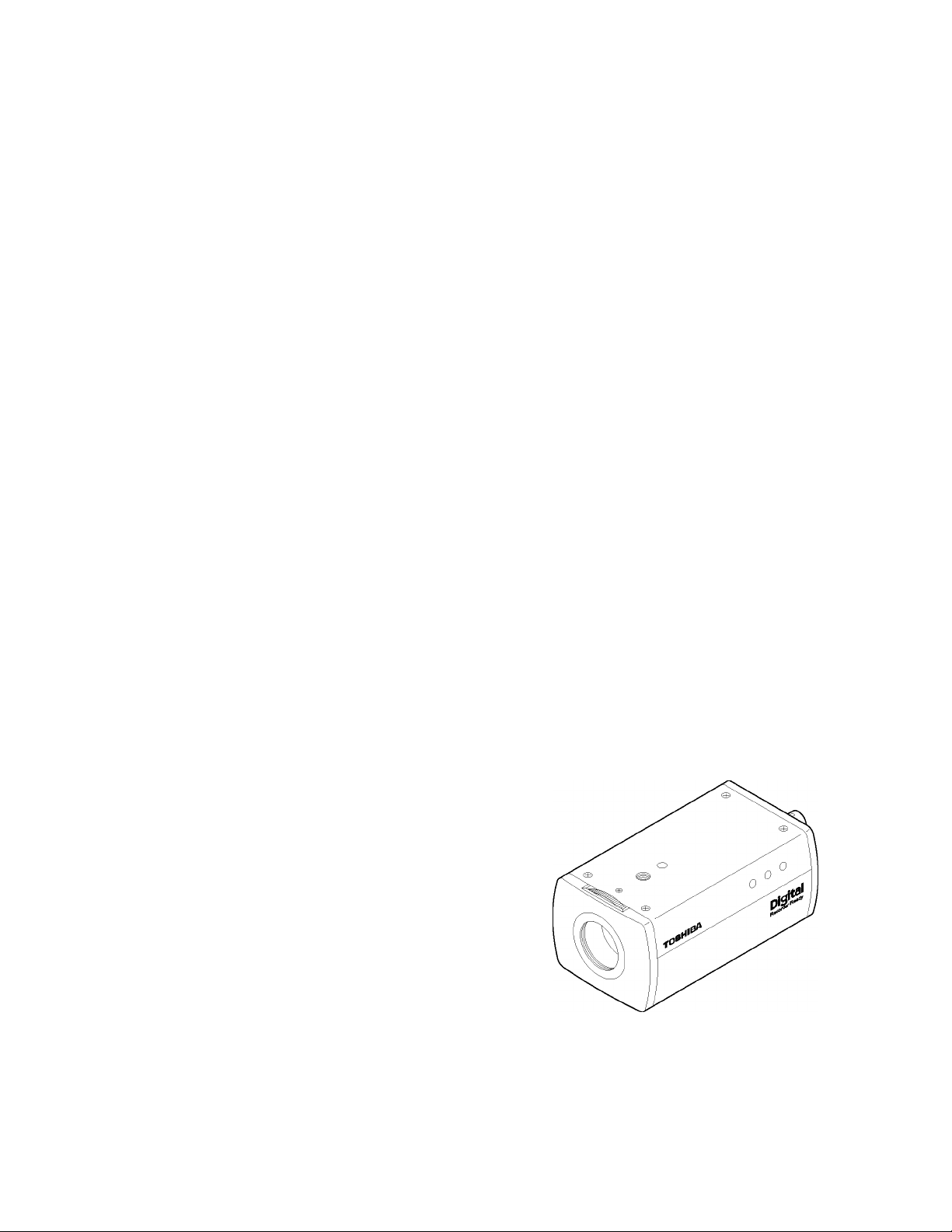
CCD CAMERA
IK-528A
PRINTED IN JAPAN, Jun., 2000
Page 2

(IK-528A)
IMPORTANT SAFEGUARDS
1.
Road Instructions
All the safety and operating instructions should be
read before the product is operated.
2.
Retain Instructions
The safety instructions and instruction manual
should be retained for future reference.
3.
Heed Warnings
All warnings on the product and in the instruction
manual should be adhered to.
4.
Follow Instructions
All operating and use instructions should be
followed.
5.
Cleaning
Disconnect this video product from the power
supply before cleaning.
6.
Attachments
Do not use attachments not recommended by the
video product manufacturer as they may cause
hazards.
7.
Water and Moisture
Do not use this video product near water-for
example, near a bath tub, wash bowl, kitchen sink,
or laundry tub, in a wet basement, or near a
swimming pool and the like.
8.
Accessories
Do not place this video product on an unstable cart,
stand, tripod, bracket or table. The video product
may fall, causing serious injury to a child or adult,
and serious damage to the product. Use only with
stand, tripod, bracket, or table recommended by
the manufacturer, or sold with the video product.
Any mounting of the product should follow the
manufacturer's instructions, and should use a
mounting accessory recommended by the
manufacturer.
9. Ventilation
This video product should never be placed near or
over a radiator or heat register. This video product
should not be placed in a built-in installation such
as a bookcase or rack unless proper ventilation is
provided or the manufacturer's instructions have
been adhered to.
10. Power Sources
This video product should be operated only from
the type of power source indicated on the marking
label. If you are not sure of the type of power
supply to your location, consult your product dealer.
11. Power-Cord Protection
Power-Supply cords should be routed so that they
are not likely to be walked on or pinched by items
placed upon or against them, paying particular
attention to cords at plugs, screws and the point
where they exit from the product.
12. Lightning
For added protection for this video product during a
lightning storm, or when it is left unattended and
unused for long periods of time, unplug it from the
wall outlet and disconnect the power supply and
cable system. This will prevent damage to the
video product due to lightning and power-line
surges.
13. Overloading
Do not overload power supply and extension cords
as this can result in a risk of fire or electric shock.
14. Object and Liquid Entry
Never push objects of any kind into this video
product through openings as they may touch
dangerous voltage points or short-out parts that
could result in a fire or electrical shock. Never spill
liquid of kind on the video product.
15. Servicing
Do not attempt to service this video product
yourself as opening or removing covers may
expose you to dangerous voltage or other hazards.
Refer all servicing to qualified service personnel.
16. Damage Requiring service
Disconnect this video product from the power
supply and refer servicing to qualified service
personnel under the following conditions.
a. when the power-supply cord or plug is damaged.
b. If liquid has been spilled, or objects have fallen
into the video product.
c. If the video product has been exposed to rain or
water.
d. If the video product does not operate normally
by following the operating instructions in the
instruction manual. Adjust only those controls that
are covered by the instruction manual as an
improper adjustment of other controls may result in
damage and will often require extensive work by a
qualified technician to restore the video product to
its normal operation.
e. If the video product has been dropped or the
cabinet has been damaged.
f. When the video product exhibits a distinct
change in performance-this indicates a need for
service.
17. Replacement Parts
When replacement parts are required, be sure the
service technician has used replacement parts
specified by the manufacturer of have the same
characteristics as the original part. Unauthorized
substitutions may result in fire, electric shock or
other hazards.
18. Safety Check
Upon completion of any service or repairs to this
video product, ask the service technician to
perform safety checks to determine that the video
product is in proper operating condition.
RISK OF ELECTRIC SHOCK
________
CAUTION TO EDUCE THE RISK OF ELECTRIC SHOCK.
DO NOT REMOVE COVER (OR BACK).
NO USER SERVICEABLE PARTS INSIDE.
REFER SERVICING TO QUALIFIED SERVICE PERSONNEL.
A
A
INFORMATION
This equipment has been tested and found to comply with the limits for a Class A digital
device, pursuant to Part 15 of the FCC Rules. These limits are designed to provide
reasonable protection against harmful interference when the equipment is operated in a
commercial environment. This equipment generates, uses , and can radiate radio
frequency energy and, if not installed and used in accordance with the instruction manual,
may cause harmful interference to radio communications. Operation of this equipmetn in a
residential area is likely to cause harmful interference in which case the user will be
required to correct the interference at his own expense.
USER-INSTALLER CAUTION : Your authority to operate this FCC verified equipment
could be voided if you make changes or modifications not expressly approved by the party
responsible for compliance to Part 15 of the FCC rules.
CAUTION
DO NOT OPEN
The lightening flash with arrowhead
symbol, within an equilateral triangle,
is intended to alert the user to the
presence of uninsulated "dangerous
voltage" within the product's enclosure
that may be of sufficient magnitude to
constitute a risk of electric shock to
persons.
The exclamation point within an
equilateral triangle is intended to alert
the user to the presence of important
operating and maintenance (servicing)
instructions in the literature
accompanying the appliance.
» The CAUTION label, shown on the left,
is attached on the bottom of camera.
WARNING :
TO REDUCE THE RISK OF FIRE OR
ELECTRIC SHOCK, DO NOT EXPOSE
THIS APPLIANCE TO RAIN OR MOISTURE.
• CAUTION
CONNECT 24V AC UL LISTED CLASS 2
POWER SUPPLY.
(0
m
o
O
m
z
m
33
>
o
m
0)
o
■D
Page 3
1. FEATURES & DESCRIPTION
c
This camera is a high resolution CCD MONOCHROME video camera
designed for EIA system. With the adoption of a CCD, the camera produces
an image with reduced lag, little geometric distortion and has good
resistance to vibration and mechanical shock. With those features shown
below, this series is suitable for surveillance application or as an input device
for an image processing system.
(1) High resolution :
The camera can produce an image with horizontal resolution over 400
TV lines.
(2) High sensitivity :
With minimum illumination at 0.032 lux (F1.2, 3200K) ensures this unit
can produce a good image even in very low light condition.
(3) Line-lock mode :
Based on this unique design, the image would be stable as viewed from
a video monitor controlled by a switcher, so this unit is suitable for
surveillance system application.
(4) Automatic electronic shutter (AES) :
3
,^3 The unit automatically adjusts shutter speed according to the subject
brightness so that the amount of exposure is steady.
(5) 4-way programmable BLC show window type. Programmable Back Light
Compensation gives Four user-selectable zone.
(6) Dynamic range boost increases Dynamic range by 40%.
(7) Easy back focus adjustment makes for easy installations.
( 2. CAUTIONS : ')
(1) In order to protect the camera, avoid placing or using it under direct
sunlight, rain or dust. (Indoor use only.)
(2) Don't touch the CCD sensor directly with your fingers. If necessary, use
soft cloth moistened with alcohol to wipe off the dust.
(3) When the camera is not in use, keep the lens or cap being attached to
protect the CCD sensor.
(4) Connect AC 24V UL listed class 2 for power supply.
(5) Don't drop your camera or give it a strong shock or vibration, or it will
incur malfunction.
(6) Keep clean the video out connector and AC 24V input terminals.
Page 4

( 5. OPERATION PROCEDURE : )
(1) Before operation make sure the power source is correct for your camera.
(2) Install lens to the camera.
(3) Connect the VIDEO output to the Video monitor. The picture will appear on the
monitor screen as the power is supplied to the camera.
(4) Adjust the focus and aperture of the lens to get a best quality image.
(5) Back focus adjustment:
In general, the back focus is calibrated in the factory. So readjustment is
unnecessary. But depending on your application, back focus readjustment may be
necessary. In this case, set the focus ring of the lens to the oo position and take a
picture at a distance of 20m or more. Then, loosen the focus lock screw and turn
the focus ring till the picture on the monitor is in focus. Now, tighten the focus lock
screw.
(6) Line - Lock mode
When two or more cameras are switched by the video switcher for monitoring on
a TV monitor, the picture may fluctuate due to different AC line phase of each
camera. In this case, adjust the V PHASE (on rear panel) trimmer to get a stable
picture. Show as below : (Default is Line - Lock)
CO
(7) Dynamic - Range Boost
It is change the video output from 115 IRE to 155 IRE when switch on. Show as
below : (Default is off)
DYNAMIC RANGE
ON
OFF
nmti
------------
(8) BLC (BACK LIGHT COMPENSATION ) Selection
When the automatic electronic iris and the auto iris lens used, the exposure
adjustment Is automatically performed so that a best picture is obtained at next
monitor zone. There are 4 ways BLC fuctlon for different application the window
area of BLC show as below:
ON
OFF
LL/INT
'
Video monitor
m
ON ratra
OFF I
_____
I L_BLC2
I
------
BLC1
Video monitor
ON
OFF J
_____
l_BLC2
-----
BLC1
Video monitor
ON
OFF ll
l_BLC2
-----
BLC1
Video monitor
ON
OFF ■
l_BLC2
-----
BLC1
Page 5

Auto -IRIS Terminal
When using an auto -iris
it needs to be connected to
Left side View
p-l.
p>
5
7J
m
C/)
c
z
o
H
o
O)
W
Page 6

(IK-540A)
en
IMPORTANT SAFEGUARDS
Road Instructions
1.
All the safety and operating instructions should be
read before the product is operated.
Retain Instructions
2.
The safety instructions and instruction manual
should be retained for future reference.
Heed Warnings
3.
All warnings on the product and in the instruction
manual should be adhered to.
Follow Instructions
4.
All operating and use instructions should be
followed.
Cleaning
5.
Disconnect this video product from the power
supply before cleaning.
Attachments
6.
Do not use attachments not recommended by the
video product manufacturer as they may cause
hazards.
Water and Moisture
7.
Do not use this video product near water-for
example, near a bath tub, wash bowl, kitchen sink,
or laundry tub, in a wet basement, or near a
swimming pool and the like.
Accessories
8.
Do not place this video product on an unstable cart,
stand, tripod, bracket or table. The video product
may fall, causing serious injury to a child or adult,
and serious damage to the product. Use only with
stand, tripod, bracket, or table recommended by
the manufacturer, or sold with the video product.
Any mounting of the product should follow the
manufacturer's instructions, and should use a
mounting accessory recommended by the
manufacturer.
Ventilation
9.
This video product should never be placed near or
over a radiator or heat register. This video product
should not be placed in a built-in installation such
as a bookcase or rack unless proper ventilation is
provided or the manufacturer's instructions have
been adhered to.
10. Power Sources
This video product should be operated only from
the type of power source indicated on the marking
label. If you are not sure of the type of power
supply to your location, consult your product dealer.
11. Power-Cord Protection
Power-Supply cords should be routed so that they
are not likely to be walked on or pinched by items
placed upon or against them, paying particular
attention to cords at plugs, screws and the point
where they exit from the product.
12. Lightning
For added protection for this video product during a
lightning storm, or when it is left unattended and
unused for long periods of time, unplug it from the
wall outlet and disconnect the power supply and
cable system. This will prevent damage to the
video product due to lightning and power-line
surges.
13. Overloading
Do not overload power supply and extension cords
as this can result in a risk of fire or electric shock.
14. Object and Liquid Entry
Never push objects of any kind into this video
product through openings as they may touch
dangerous voltage points or short-out parts that
could result in a fire or electrical shock. Never spill
liquid of kind on the video product.
15. Servicing
Do not attempt to service this video product
yourself as opening or removing covers may
expose you to dangerous voltage or other hazards.
Refer all servicing to qualified service personnel.
16. Damage Requiring service
Disconnect this video product from the power
supply and refer servicing to qualified service
personnel under the following conditions.
a. when the power-supply cord or plug is damaged.
b. If liquid has been spilled, or objects have fallen
into the video product.
c. if the video product has been exposed to rain or
water.
d. If the video product does not operate normally
by following the operating instructions in the
instruction manual. Adjust only those controls that
are covered by the instruction manual as an
improper adjustment of other controls may result in
damage and will often require extensive work by a
qualified technician to restore the video product to
its normal operation.
e. If the video product has been dropped or the
cabinet has been damaged.
f. When the video product exhibits a distinct
change in performance-this indicates a need for
service.
17. Replacement Parts
When replacement parts are required, be sure the
service technician has used replacement parts
specified by the manufacturer of have the same
characteristics as the original part. Unauthorized
substitutions may result in fire, electric shock or
other hazards.
18. Safety Check
Upon completion of any service or repairs to this
video product, ask the service technician to
perform safety checks to determine that the video
product is in proper operating condition.
CAUTION
A
CAUTION TO EDUCE THE RISK OF ELECTRIC SHOCK.
REFER SERVICING TO QUALIFIED SERVICE PERSONNEL.
RISK OF ELECTRIC SHOCK
DO NOT OPEN
DO NOT REMOVE COVER (OR BACK).
NO USER SERVICEABLE PARTS INSIDE.
A
' The CAUTION label, shown on the left,
is attached on the bottom of camera.
The lightening flash with arrowhead
A
symbol, within an equilateral triangle,
is intended to alert the user to the
presence of uninsulated "dangerous
voltage" within the product's enclosure
that may be of sufficient magnitude to
WARNING :
TO REDUCE THE RISK OF FIRE OR
ELECTRIC SHOCK, DO NOT EXPOSE
THIS APPLIANCE TO RAIN OR MOISTURE.
constitute a risk of electric shock to
A
persons.
The exclamation point within an
equilateral triangle is intended to alert
the user to the presence of important
operating and maintenance (servicing)
instructions in the literature
accompanying the appliance.
CAUTION
CONNECT 24V AC UL LISTED CLASS 2
POWER SUPPLY.
FIELD INSTALLATION MARKING :
WORDED ; "THIS INSTALLATION SHOULD
BE MADE BY A QUALIFIED SERVICE
PERSON AND SHOULD CONFORM TO
ALL LOCAL CODES."
INFORMATION
This equipment has been tested and found to comply with the limits for a Class A digital
device, pursuant to Part 15 of the FCC Rules. These limits are designed to provide
reasonable protection against harmful interference when the equipment is operated in a
commercial environment. This equipment generates, uses , and can radiate radio
frequency energy and, if not installed and used in accordance with the instruction manual,
may cause harmful interference to radio communications. Operation of this equipmetn in a
residential area is likely to cause harmful interference in which case the user will be
required to correct the interference at his own expense.
USER-INSTALLER CAUTION : Your authority to operate this FCC verified equipment
could be voided if you make changes or modifications not expressly approved by the party
Page 7

( 1. FEATURES & DESCRIPTION : ) ( 2. CAUTIONS : )
This camera is a high resoiution CCD MONOCHROME video camera
designed for EiA system. With the adoption of a CCD, the camera produces
an image with reduced lag, little geometric distortion and has good
resistance to vibration and mechanical shock. With those features shown
below, this series is suitable for surveillance application or as an input device
for an image processing system.
(1) High resolution :
The camera can produce an image with horizontal resolution over 570
TV lines.
(2) High sensitivity :
With minimum illumination at 0.015 lux (FI.2, 3200K, AGC WIDE)
ensures this unit can produce a good image even in very low light
condition.
(3) Since the camera uses AC 24V ~/DC12 — , it can be installed and built
into system easily.
O)
(4) Line-lock mode :
Based on this unique design, the image would be stable as viewed from
a video monitor controlled by a switcher, so this unit is suitable for
surveillance system application.
(5) Automatic electronic shutter (AES) ;
The unit automatically adjusts shutter speed according to the subject
brightness so that the amount of exposure is steady.
(6) 4-way programmable BLC show window type. Programmable Back Light
Compensation gives Four user-selectable zone.
(7) Dynamic range boost increases Dynamic range by 40%.
(8) Easy back focus adjustment and Menu-Driven set-up makes for easy
installations.
(1) In order to protect the camera, avoid placing or using it under direct
sunlight, rain or dust. (Indoor use only.)
(2) Don't touch the CCD sensor directly with your fingers, If necessary, use
soft cloth moistened with alcohol to wipe off the dust.
(3) When the camera is not in use, keep the lens or cap being attached to
protect the CCD sensor.
(4) Connect AC 24V UL listed class 2 or DC 12V for power supply. Never
input AC 24V and DC 12V at the same time.
(5) Don’t drop your camera or give it a strong shock or vibration, or it will
incur malfunction.
(6) Keep clean the video out connector and Power input terminals.
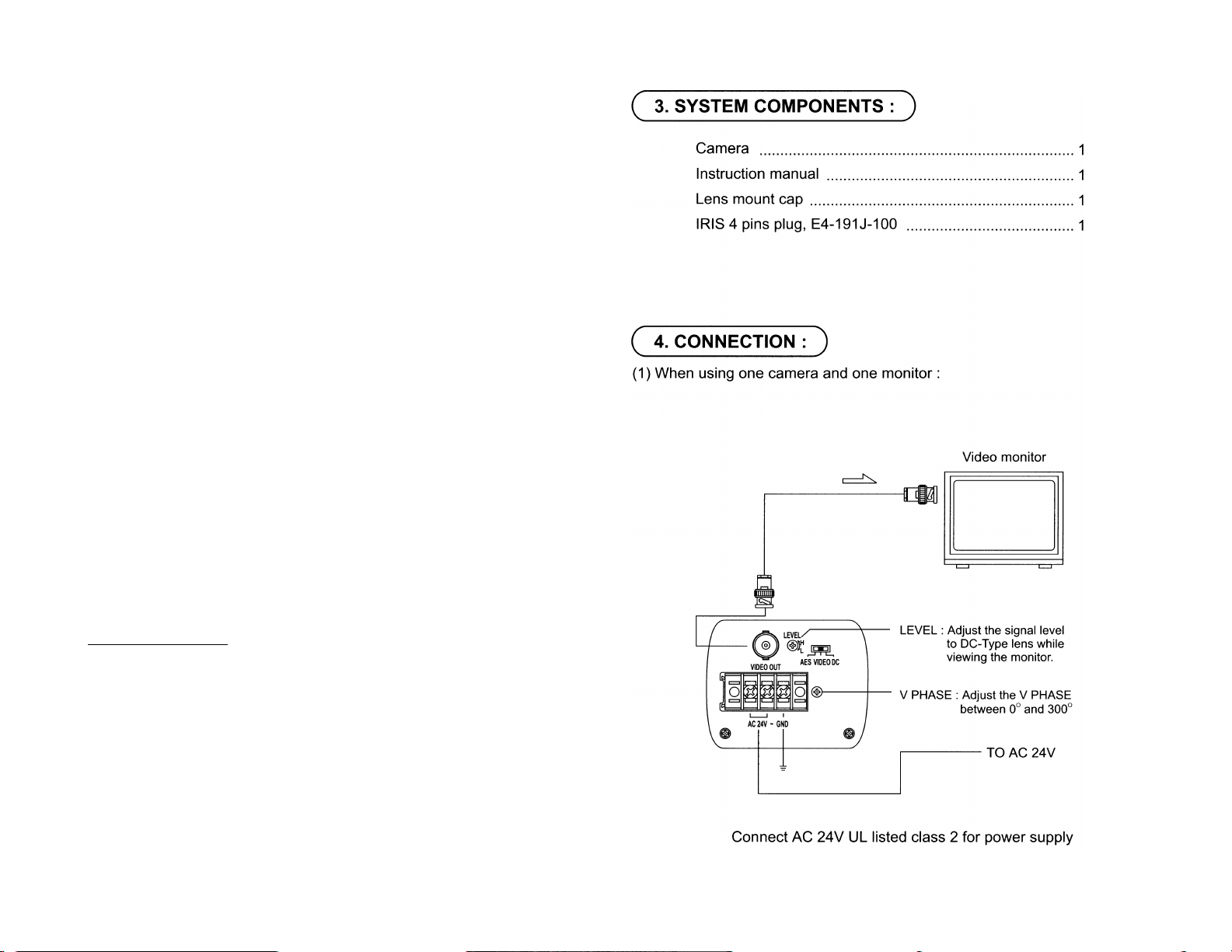
( 3. SYSTEM COMPONENTS : )
Camera .......................................................................................1
Instruction manual ...................................................................^
Lens mount cap
IRIS 4 pins plug, E4-191J-100
..........................................................................
.................................................
i
^
Page 8

(3) When using the auto IRIS lens (with amplifier):
(a) Set the slide switch (on rear panel) to VIDEO position.
(b) Connect the Al iens cable to the IRIS connector on left side of camera.
(4) When using the auto IRIS lens (without amplifiter):
(a) Set the slide switch (on rear panel) to DC position.
(b) Connect the auto IRIS lens cable to the IRIS connector on left side of
camera.
NOTE : Please refer to the pin definitions and figure shown below to
ensure correct operation.
IRIS pin definitions
VIDEO
+ 12V
1
NC
2
3
VIDEO
4
GND
DC
DAMP - (y)
damp + (r)
DRIVER + (wh)
DRIVER - (g)
( 5. OPERATION PROCEDURE : )
(1) Before operation make sure the power source is correct for your camera.
(2) Install lens to the camera.
(3) Connect the VIDEO output to the Video monitor. The picture will appear on the
monitor screen as the power is supplied to the camera.
(4) Adjust the focus and aperture of the lens to get a best quality image.
(5) Back focus adjustment:
In general, the back focus is calibrated in the factory. So readjustment is
unnecessary. But depending on your application, back focus readjustment may
be necessary. In this case, set the focus ring of the lens to the oo position and
take a picture at a distance of 20m or more. Then, loosen the focus lick screw
and turn the focus ring till the picture on the monitor is in focus. Now tighten the
focus lock screw.
Page 9

5-1. Menu-Driven set-up
The setting menus of hierarchy are shown below and with on-screen character
displays.
SHUTTER
AGC
SYNC
I MENU]—I BLC
DYRANGE
EXIT
CANCEL
DEFAULT
0| AUTO H 1/60 H 1/100 hflT25^ 1/500 H 1/1K h|
L| 1/2K H 1/5K Hi/10KHi/100K|
ol OFF K ON H WIDE |
Ol INT H LL I
OPOFTH BLC1 h-f BLC2 H BLC3 I
oroFnHBOosTi
AUTO (AES)
1/60, 1/100, 1/250, 1/500, 1/1K, 1/2K, 1/5K, 1/10K, 1/100K(MES)
When the rear panel switch is turned to VIDEO or DC, the exposure time
is fixed 1/60 sec, and shutter mode turn to IRIS.
5-3-2. AGC
Move the cursor to the position shown in Fig.
Using SELECT switches, to select ON, WIDE,
OFF
A. ON (Standard position, max gain = 18dB)
B. WIDE (High-Sensitivity position, max gain
= 32dB)
/
SHUTTER
AGC
SYNC
BLC OFF
DYRANGE OFF
EXIT CANCEL DEFAULT
V
C. OFF
AUTO
ESBI
LL
\
/
5-3-3. SYNC
5-2. Setting switches and the functions
On the side panel of the camera there are three push button switches as
shown below :
Switch name Main function
Move the cursor to the position shown in Fig.
Using the SELECT switches, to select INT or LL
in the SYNC item.
A. INT : The camera is in the internal SYNC
mode.
B. LL : The camera is in the Line-Lock Mode.
SELECT Setting mode call on / off, setting entry
00
Y Setting item selection (down)
Setting 0 to 300 degree by adjusting
the V phase of rear panel.
SHUTTER AUTO
AGC ON
SYNC
BLC OFF
DYRANGE OFF
EXIT CANCEL DEFAULT
A Setting item selection (up)
5-3. Setting mode call and basics
Press the SELECT switch down about 2 seconds then
menu will appear on the display.
5-3-1. Shutter (Exposure time)
Set the slide switch (on rear panel) to AES /
(MES) position. Move the cursor to the position
as shown in Fig. Using the SELECT switches,
choose the shutter speed from AUTO through
1/100K
/
SHUTTER AUTO
AGC
SYNC
BLC
DYRANGE
EXIT CANCEL DEFAULT
V
SHUTTER
AGC ON
SYNC LL
BLC OFF
DYRANGE OFF
EXIT CANCEL DEFAULT
ON
LL
OFF
OFF
5-3-4. BLC (BACK LIGHT COMPENSATION)
Move the cursor to the position shown in Fig.
Using the SELECT switches, select the OFF,
BLC1, BLC2, BLC3.When the automatic
electronic iris and the auto iris lens used the
exposure adjustment is automatically performed
SHUTTER AUTO
AGC ON
SYNC LL
BLC
DYRANGE OFF
EXIT CANCEL DEFAULT
so that a best picture is obtained at next monitor
zone. There are 4 ways BLC function for different application. The window
area of BLC show as below:
J
OFF
Video monitor
BLC1
Video monitor
BLC2
Video monitor
BLC3
Video monitor
i f 11
WTjjÈ
BLC area will appear on the monitor screen as the BLC function
is sellected.
Page 10

5-3-5. DYRANGE (Dynamic - Range Boost)
Move the cursor to the position in Fig. Using the
SELECT switches, SELECT the OFF, BOOST.
It is changed the video output from 115 IRE to
155 IRE.
A. OFF (Standard position, max 115 IRE)
B. Boost (High dynamic range position, Max 155
IRE)
5-3-6. EXIT
Move the cursor to the position in Fig. Press the
SELECT switch when save all settings and exit.
SHUTTER AUTO
AGC ON
SYNC LL
BLC OFF
DYRANGE Cl
EXIT CANCEL DEFAULT
SHUTTER AUTO
AGC ON
SYNC LL
BLC OFF
DYRANGE OFF
[EEiCANCEL DEFAULT
V_____________________J
CD
5-3-7. CANCEL
Move the cursor to the position in Fig. Press the
SELECT switch, exit menu immediately and don't
save.
5-3-8. DEFAULT
Move cursor to the position in Fig. Press the
SELECT switch to recall the factory settings.
Default position is below :
SHUTTER
AGC
SYNC
BLC
DYRANGE
AUTO / IRIS
ON
LL
OFF
OFF
SHUTTER AUTO
AGC ON
SYNC LL
BLC OFF
DYRANGE OFF
EXIT[
SHUTTER AUTO
AGC ON
SYNC LL
BLC OFF
DYRANGE OFF
EXIT CANCEliiTaTg
¡DEFAULT
 Loading...