

Toshiba IK-4KE Instruction Manual
CAMERA CONTROL UNIT
cev.fr
INSTRUCTION MANUAL
IK-4KE
For Customer Use
Enter below the Serial No.
which is located on the
bottom of the cabinet. Retain
this information for future reference.
Model No.: IK-4KE
Serial No.:
U.S.A INFORMATION
NOTE: This equipment has been tested and found to comply with the limits for a Class A digital de vice, pursuant to P art
15 of the FCC Rules. These limits are designed to pro vide reasonable protection against harmful interf erence when the
equipment is operated in a commercial environment. This equipment generates, uses, and can radiate radio frequency
energy and, if not installed and used in accordance with the instruction manual, may cause harmful interference to
radio communications. Operation of this equipment in a residential area is lik ely to cause harmful interference in which
case the user will be required to correct the interference at his own expense.
USER-INSTALLER CAUTION: Your authority to operate this FCC verified equipment could be voided if
you make changes or modifications not expressly approved by the party responsible for compliance to
Part 15 of the FCC Rules.
Following information is only for EU-member states:
In residential areas this product may cause radio interference, therefore this product must not be used
in residential areas.
The use of the symbol indicates that this product may not be treated as household waste.
By ensuring this product is disposed of correctly, you will help prevent potential negative
consequences for the environment and human health, which could otherwise be caused by
inappropriate waste handling of this product. For more detailed information about the takeback and recycling of this product, please contact your supplier where you purchased the
product or consult.
This manual is made from recycled paper.

Protection of Personal Information
Images taken by the camera that reveal the likeness of an individual person may be considered
personal information. To disclose, exhibit or transmit those images over the internet or otherwise,
consent from such individual person may be required. You are solely responsible to obtain such
consent.
Limitation of Usage
The product is not designed for any “critical applications.” “Critical applications” means life support
systems, exhaust or smoke extraction applications, medical applications, commercial aviation,
mass transit applications, military applications, homeland security applications, nuclear facilities or
systems or any other applications where product failure could lead to injury to persons or loss of life
or catastrophic property damages. Accordingly, Toshiba disclaims any and all liability arising out of
the use of the product in any critical applications.
TABLE OF CONTENTS
1. CAUTIONS ON USE AND INSTALLATION ...............................................................................................6
2. COMPONENTS ..........................................................................................................................................6
3. ITEMS CONTROLLED BY THE SCREEN DISPLAY .................................................................................7
4. NAMES AND FUNCTIONS ........................................................................................................................9
5. CONNECTION..........................................................................................................................................10
5. 1 Standard Connection .......................................................................................................................10
5.1.1 4K mode ................................................................................................................................10
5.1.2 1080 i/p mode .......................................................................................................................11
5. 2 Cautions on Connection ...................................................................................................................11
5. 3 Connector Pin Assignments .............................................................................................................12
6. OPERATION .............................................................................................................................................13
6. 1 Automatic Black Balance .................................................................................................................13
6. 2 White Balance ..................................................................................................................................13
6. 3 Scene File ........................................................................................................................................15
6. 4 Gain .................................................................................................................................................15
6. 5 Shading Correction ..........................................................................................................................16
6. 6 Switching of Video Signal Output .....................................................................................................17
6. 7 Freeze operation ..............................................................................................................................17
7. MODE SETTING BY ON SCREEN DISPLAY ..........................................................................................18
7. 1 Using the Menus ..............................................................................................................................18
7. 2 Menus ..............................................................................................................................................19
( 1 ) SHUTTER (Electronic shutter).........................................................................................................19
(1. 1) Changing the setting in AUTO mode .....................................................................................20
(1. 2) Changing the setting in MANUAL mode ................................................................................22
(1. 3) Changing the setting in SS (Synchro. Scan) mode ................................................................22
4

( 2 ) GAIN (Video gain)............................................................................................................................23
(2. 1) Changing the setting in AUTO (AGC: Automatic gain control) mode .....................................23
(2. 2) Changing gain in MANUAL mode ..........................................................................................23
( 3 ) WHT BAL (White balance) ...............................................................................................................24
(3. 1) Changing the setting in AWB (Automatic White Balance) mode ...........................................24
(3. 2) Changing gain in MANUAL mode ..........................................................................................25
( 4 ) PROCESS1 .....................................................................................................................................26
(4. 1) Changing gamma correction ON/OFF ...................................................................................26
(4. 2) Changing gamma correction level .........................................................................................26
(4. 3) Changing black gamma correction level ................................................................................27
(4. 4) Changing the knee correction point .......................................................................................27
(4. 5) Changing the knee correction slope ......................................................................................27
(4. 6) Changing pedestal .................................................................................................................28
(4. 7) Change of white clip ..............................................................................................................28
( 5 ) PROCESS2 .....................................................................................................................................29
(5. 1) Changing detail (outline) gain ................................................................................................29
(5. 2) Change of detail boost frequency ..........................................................................................29
(5. 3) Change of horizontal and vertical detail balance ...................................................................29
( 6 ) PROCESS3 .....................................................................................................................................30
(6. 1) Changing matrix color correction ON/OFF ...........................................................................30
(6. 2) Selection of color for correction .............................................................................................30
(6. 3) Changing HUE and GAIN of selected color ...........................................................................30
(6. 4) Changing the total Chroma gain (simultaneously for all colors in the matrix) ........................30
( 7 ) SYNC ...............................................................................................................................................31
(7. 1) INT screen .............................................................................................................................31
(7. 2) Changing EXT. setting ...........................................................................................................31
( 8 ) OPTION ...........................................................................................................................................32
(8. 1) Changing shading correction mode .......................................................................................32
(8. 2) Changing manual shading correction mode ..........................................................................32
(8. 3) Changing detail signal output ................................................................................................32
(8. 4) Change of vertical inversion setting .......................................................................................33
(8. 5) Change of horizontal inversion setting ...................................................................................33
(8. 6) Switching of inversion mode display ......................................................................................33
(8. 7) Changing the freeze display ..................................................................................................33
(8. 8) Changing 4K OSD (On Screen Display) output .....................................................................34
(8. 9) Changing the output mode ....................................................................................................34
(8. 10) Changing RS-232C baud rate .............................................................................................34
( 9 ) Setting USER area ..........................................................................................................................35
( 10 ) Returning to factory settings ..........................................................................................................36
7. 3 External Sync ...................................................................................................................................36
( 1 ) External sync signal input conditions ...............................................................................................36
( 2 ) External sync frequency range ........................................................................................................36
( 3 ) Using the unit with external sync signal ...........................................................................................36
7. 4 Synchro. Scan Operation .................................................................................................................36
( 1 ) Setting by 1H ...................................................................................................................................36
8. BEFORE MAKING SERVICE CALL ........................................................................................................37
9. SPECIFICATIONS ....................................................................................................................................38
10. EXTERNAL APPEARANCE DIAGRAM ................................................................................................39
5

1. CAUTIONS ON USE AND INSTALLATION
•Handlingtheunit.
Do not drop, jolt, or vibrate, as this may result in
damage to the unit and may cause problems. Treat the
camera cables carefully to prevent cable problems,
such as breaks in the cable and loose connections.
•Installthecamerainalocationfreefromnoise.
If the camera or the cables are located near power
utility lines or a TV, etc. undesirable noise may appear
on the screen. In such a case, try to change the
location of the camera or the cable wiring.
•Operatingambienttemperatureandhumidity.
Do not use the camera in places where temperature
and humidity exceed the specifications. Picture quality
will deteriorate and internal parts may be damaged.
Be particularly careful when using in places exposed
to direct sunlight. When shooting in hot en vironments,
depending on the conditions of the object and the
camera (for example when the gain is increased),
noise in the form of vertical strips or white dots may
occur. This is not a malfunction.
•Whennotusingthecameraforextendedperiods
of time.
Switch the control unit off and disconnect the power
supply.
•Avoidusingorstoringthecamerainthefollowing
places:
Places filled with highly flammable and corrosive gas.
Places near gasoline, benzene, or paint thinner.
Places subject to strong vibration.
Places containing chemicals (such as pesticides),
rubber or vinyl products for extended periods of time.
•Thisproductisforindooruseonly.
The following descriptions are for a camera head “IK4KH” connected to this camera control unit.
•Donotshootintenselight.
If a strong light is imaged, vertical stripes or traverse
bands may appear on the screen but this is not a
failure.
•Moire
A moire pattern is an interference pattern generated
when two repetitive line patterns overlap. This is not a
malfunction. Eliminating the repetitive line patterns, or
aligning the two patterns, will eliminate the moire.
•Handlingofthecameraheadandprotectioncap.
Keep the camera head and protection cap away
from children as they may pose a choking hazard.
The protection cap protects the image sensing plane
when the lens is removed from the camera head, do
not discard the protection cap.
•Whencleaningthecamera.
Unplug the power source before cleaning. Clean
with a soft dry cloth only. Do not use chemicals or
chemically treated cloths. Chemicals may damage
coatings and printed letters. When cleaning the lens,
use lens cleaning paper.
•Installationwithoutatripod.
Before installing the camera head, make sure that the
location can withstand the total weight of the camera
head.
If this is not the case, reinforce the area to prev ent the
unit from dropping, which may result in damage to the
unit or personal injury.
2. COMPONENTS
(1) Camera Control Unit ......................................................................................................................1
(2) Accessories
(a) Instruction manual .................................................................................................................. 1
6
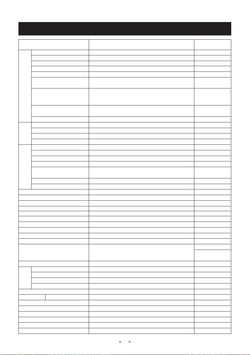
3. ITEMS CONTROLLED BY THE SCREEN DISPLAY
Item Available selections
MODE AUTO, MANUAL, SS MANUAL
AUTO level -100 – 0 – 100 0
AUTO exposure metering PEAK/AVE, MEDIAN
Electronic shutter
AUTO peak/average 00 : 10 – 10 : 00 00 : 10
AUTO response speed 1 – 10 – 20 10
AUTO area
Maximum AUTO shutter
speed
MANUAL shutter speed
Syncro. scan 1/1125H – 1124/1125H, OFF OFF
MODE AUTO, MANUAL, OFF OFF
Gain
AUTO maximum gain 0dB to 24dB 24dB
AUTO minimum gain
MANUAL gain -6dB to 24dB 0dB
MODE AWB, MANUAL AWB
White balance
Color temperature 3200K, 5600K 3200K
AWB R PAINT -10 – 0 – 10 0
AWB B PAINT -10 – 0 – 10 0
AWB area
MANUAL R GAIN -100 – 0 – 100 0
MANUAL B GAIN -100 – 0 – 100 0
Gamma correction ON, OFF ON
Gamma correction level -10 – 0 – 10 0
Black gamma correction level LOW, NORMAL, HIGH NORMAL
Knee correction point 70%, 75%, 80%, 85%, 90%, 95%, 100% 85%
Knee correction slope
Master pedestal -200 – 0 – 200 0
Red pedestal -100 – 0 – 100 0
Blue pedestal -100 – 0 – 100 0
White clip 100% − 109% 109%
Detail gain 0 − 10 − 31 10
Detail boost frequency 1 − 10 − 16
HV balance 8/16 − 16/16 − 24/16 (ratio of V/H) 16/16
Correction ON/OFF ON, OFF ON
Matrix
Selection of correction color R, R-Ye, Ye, Ye-G, G, G-Cy, Cy , Cy-B , B , B-Mg, Mg, Mg-R R
Phase -15 – 0 – 15 0
Gain -15 – 0 – 15 0
Chroma gain
Ext. Sync
Shading correction mode SET, MANUAL, OFF OFF
Manual shading correction -128 – 0 – 127 0
Detail signal output ON, OFF OFF
Vertical inversion ON, OFF OFF
Horizontal inversion ON, OFF OFF
Inversion mode display switch ON, OFF OFF
H phase adjustment
PRESET A, PRESET B, PRESET C, PRESET D, PRESET E,
USER (USER area is possible to set in 64 zones)
1/200s, 1/250s, 1/300s, 1/350s, 1/400s, 1/450s, 1/500s,
1/550s, 1/600s, 1/700s, 1/800s, 1/900s, 1/1000s,
1/1200s, 1/1500s, 1/2000s, 1/4000s, OFF
OFF, 1/100s, 1/125s, 1/250s, 1/500s, 1/1000s, 1/2000s,
1/3000s, 1/4000s, 1/5000s, 1/10000s
-6dB to 0dB -6dB
PRESET A, PRESET B, PRESET C, PRESET D, PRESET E,
USER (USER area is possible to set in 64 zones)
1 – 8 – 16 8
-31 − 0 − 31 0
-650 – 0 – 650 0
Preset value
(Factory setting)
PEAK/AVE
PRESET A
OFF
OFF
PRESET A
16 (4K mode)
10 (1080p mode)
(1080i mode)
7

Item Available selections
Changing the FREEZE display ON, OFF ON
4K OSD output
Output mode 4K, 1080p, 1080i 4K
RS-232C baud rate 9600bps, 19200bps 9600bps
A, B, C, D A
Preset value
(Factory setting)
8
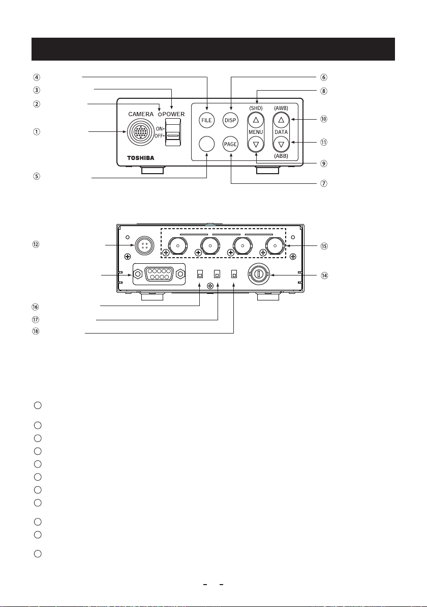
4. NAMES AND FUNCTIONS
FILE button
POWER switch
POWER LED
Camera cable
for “IK-4KH”
terminal
FREEZE button
DC IN 12V terminal
REMOTE terminal
⑬
KEY LOCK switch
FORMAT switch
SYNC switch
DC IN 12V
1
342
FREEZE
[Front]
A B C D
REMOTE
1 2 3 4 5
87 96
FORMAT SYNCKEY LOCK
ON
OFF5059.94INOUT
[Rear]
3G/HD-SDI
SYNC IN/OUT
DISP button
MENU UP
(SHD) button
DATA UP
(AWB) button
DATA DOWN
(ABB) button
MENU DOWN
button
PAGE button
3G/HD-SDI A, B, C, D
terminal
SYNC IN/OUT terminal
1
Camera cable for “IK-4KH”
terminal
2
POWER LED
3
POWER switch
4
FILE button
5
FREEZE button
6
DISP button
7
PAGE button
8
MENU UP (SHD) button
9
MENU DOWN button
10
DATA UP (AWB) button
11
DATA DOWN (ABB) button
Where the camera cable for “IK-4KH” is connected.
Illuminates to indicate the unit is powered on.
Turns power on or off.
To switch the scene files.
To freeze the display.
Changes the display mode.
To switch and select menus.
To select the function to be confirmed or changed on the menu.
(Also used when performing auto shading correction.)
To select the function to be confirmed or changed on the menu.
To change the value of the function selected by the MENU (UP/DOWN) button.
(Also used when performing an AWB.)
To change the value of the function selected by the MENU (UP/DOWN) button.
(Also used when performing an ABB.)
9
12
Lens
Ω
DC IN 12V terminal
13
REMOTE terminal
14
SYNC IN/OUT terminal
15
3G/HD-SDI A, B, C, D terminal
16
KEY LOCK switch
17
FORMAT switch
18
SYNC switch
Accepts a DC power input (12V).
To connect to a RS-232C device for remote control function.
Used when the camera output signal is synchronized to an external signal or
when a synchronized signal is output. (BNC connector)
Image signal output terminal for 3G/HD-SDI formats. (BNC connector)
Enables/disables buttons
Switches between 59.94Hz and 50Hz.
Switches between input and output of synchronized signals from
SYNC IN/OUT terminals in
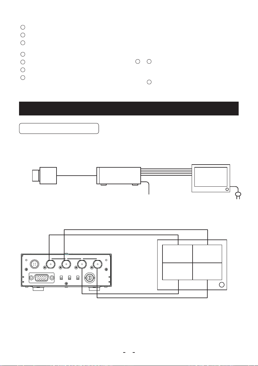
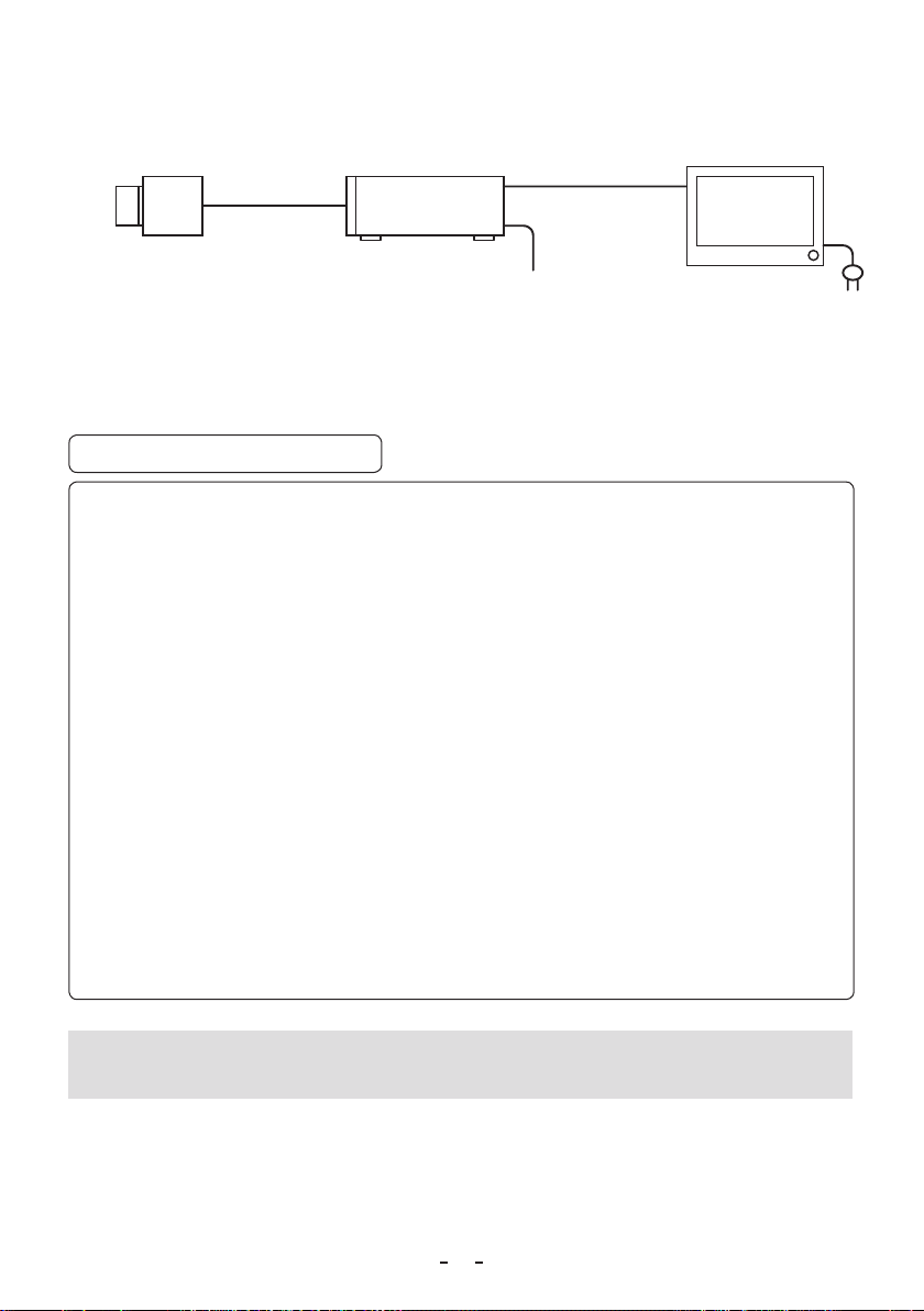
5. CONNECTION
5. 1 Standard Connection
5. 1. 1 In case output mode is 4K
4
to 11.
14
.
(commercial
product)
Camera
Head
Camera Cable
for IK-4KE
option
(
)
IK-4KE
Camera
Control unit
3G/HD-SDI
x 4
DC IN 12V
IK-4KH
(option)
DC power supply
(option)
* 3G/HD-SDI A, B, C, D terminals and screen positioning are shown below.
DC IN 12V
1
A B C D
342
REMOTE
1 2 3 4 5
87 96
3G/HD-SDI
FORMAT SYNCKEY LOCK
ON
OFF5059.94INOUT
SYNC IN/OUT
Coaxial cable × 4, 75
(commercial
product)
4K monitor
3G-SDI × 4 TV input
(commercial product)
Upperleft Upperright
Lowerleft Lowerright
10
5. 1. 2 In case output mode is 1080p or 1080i
Lens
(commercial
product)
Camera
Head
Camera Cable
for IK-4KE
(option)
IK-4KE
Camera
Control unit
3G/HD-SDI
DC IN 12V
Coaxial cable, 75Ω
(commercial
product)
IK-4KH
(option)
* 3G/HD-SDI A, B, C, D terminals output the same signal.
DC power supply
(option)
SDI monitor
3G/HD-SDI TV
(commercial product)
5. 2 Cautions on Connection
• When connecting the camera cables, be sure to turn off the camera control unit and any other equipment
connected to it.
• For DC power supply connecting to DC IN 12V terminal, use class II DC power supply approved according
to EN60950-1 in Europe. or use UL listed and/or CSA approved ungrounded type AC adaptor with the
specifications described below in U.S.A. or Canada.
Power supply voltage : 12V DC ±10%
Current rating : More than 1.5A
Ripple voltage : Less than 50 mV (p–p)
Connector : HR10A–7P–4S by HIROSE electronics Co. Ltd
Pins 1, 2 : +12V
Pins 3, 4 : GND
• If the securing screw on the connector of the camera cable loosens, noise may appear on the screen. Be sure
to tighten the connector completely.
• Only use the specic optional camera heads with this camera controller.
The use of any other camera heads may cause damage to the control unit and camera head.
• The video signal output of this camera control unit has no function for automatically selecting output according
to the monitor TV. Therefore, be sure to switch the output mode of this camera control unit according to the
monitor as no image will be displayed on the monitor if the camera output mode and the monitor input mode
do not match. For switching, refer to the item 6.6 “Switching of Video Signal Output”.
• SDI interface
The SDI (serial digital interface) is a high-speed serial interface standard used mainly in commercial video
equipment. This unit supports both HD-SDI and 3G-SDI.
When image output is “4K” or “1080p”, 3G-SDI output is used. When image output is “1080i”, HD-SDI output
is used.
Use a 3G/HD-SDI compatible cable to connect to the 3G/HD-SDI terminal.
Note:
The image may not appear on the monitor's screen immediately, depending on the conditions and the type of
monitor.
11
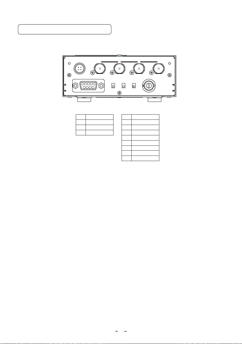
5. 3 Connector Pin Assignments
The rear panel of the camera control unit has the following connectors:
DC IN 12V; REMOTE; SYNC IN/OUT and 3G/HD-SDI A, B, C, D terminals. Use the appropriate cables to connect
with these connectors.
DC IN 12V
1
342
A B C D
REMOTE
1 2 3 4 5
87 96
3G/HD-SDI
FORMAT SYNCKEY LOCK
ON
OFF5059.94INOUT
SYNC IN/OUT
DC IN 12V terminal REMOTE terminal
1 +12V 1 2 +12V 2 TXD
3 GND 3 RXD
4 GND 4 -
5 GND
6 7 8 9 -
12
6. OPERATION
A camera head needs to be connected to this camera control unit from this section on.
1
Refer to the item “5. CONNECTION”, connect the equipment correctly.
2
Turn on the connected equipment and the camera.
3
When using the camera for the first time and when replacing the camera head, be sure to perform the ABB
adjustment, refer to the item “6.1 Automatic Black Balance”.
4
Aim the lens at the object, adjust the lens iris adjustment, focus adjustment, etc.
5
Refer to the item “6.2 White Balance”, make the adjustment.
6
Refer to the items “6.3 Scene File, 6.4 Gain, 7. MODE SETTING BY THE ON SCREEN DISPLAY”, select the
necessary items.
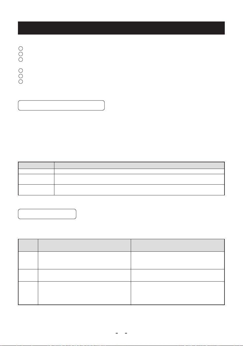
6. 1 Automatic Black Balance
Black balance adjustment is necessary to get the correct black picture level.
• Close the lens iris.
• If the color bar pattern is displayed on the screen or if the index menu/menu is displayed, press the [DISP] button to
disable the color bar pattern or the character display.
• Hold the [DATA DOWN] button for approx. 1 second.
• When the black balance adjustment operation starts, the character ABB blinks on the screen.
• When the black balance adjustment operation nishes, the character ABB stops blinking and the result appears for
approx. 1 second.
Display Meaning
ABB OK Automatic black balance adjustment finished correctly.
ABB NG
CLOSE LENS
ABB NG Automatic black balance adjustment cannot be performed.
Automatic black balance adjustment cannot be perf ormed because the lens iris is open. Close
the lens iris.
Operate the automatic black balance again.
6. 2 WhiteBalance
For white balance adjustment of this unit, AWB (Automatic White Balance) and MANUAL (Manual white balance)
adjustments are provided. Refer to the items “7.2 (3) WHT BAL (White balance), 7. MODE SETTING BY ON SCREEN
DISPLAY”, select the desired mode.
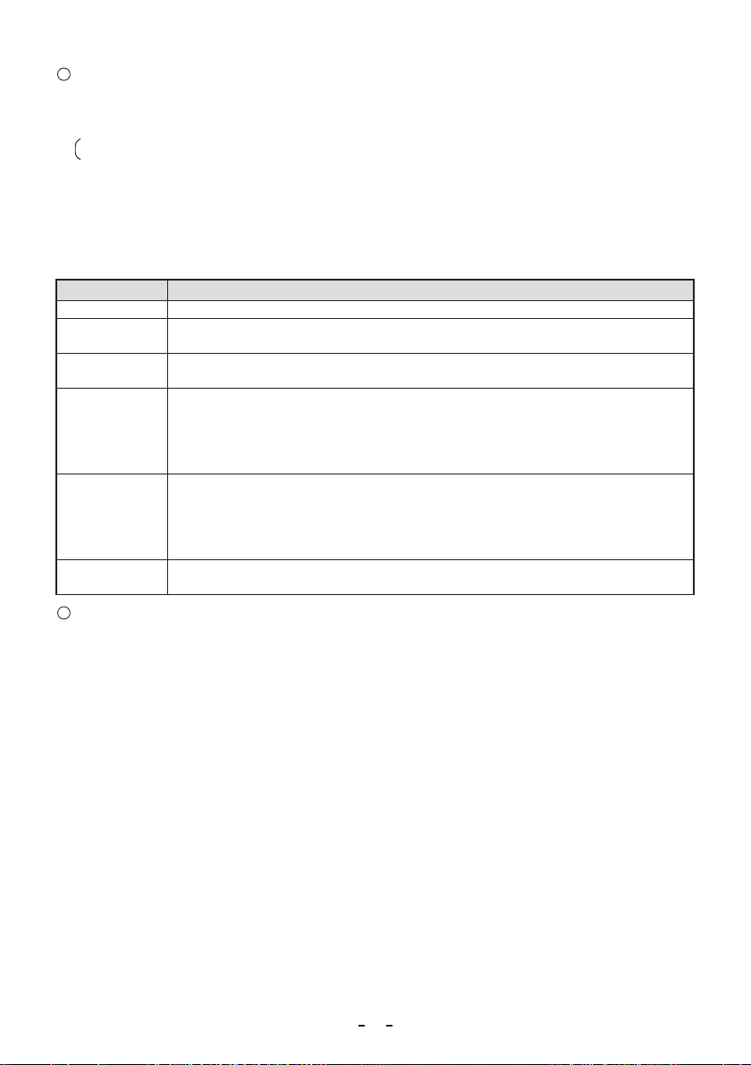
(AutomaticWhiteBalance)
AWB
Outline Adjust white balance by displaying a white object
inside the area set by AWB menu and hold the
[DATA UP] button for approx. 1 second.
Features Automatically adjusts red and blue balance based
on green for the object in the designated area.
Note When no white object exits in the designated area
or lighting is too blight or too dark, AWB NG is
displayed and automatic white balance adjustment
can not be performed.
Adjust the white balance manually using the WHT
BAL menu while shooting a white object.
White balance can be set manually.
Adjustment is performed by confirming with a
monitor etc.
MANUAL
(ManualWhiteBalance)
13
1
AWB (Automatic white balance)
• Set the MODE to AWB on the WHT BAL menu.
Change the C.TEMP (color temperature conversion) setting, if necessary.
(Refer to the item “7.2 (3) WHT BAL (White balance)”.)
3200K : Appropriate for indoor shooting.
5600K : Appropriate for outdoor shooting.
• If the color bar pattern is displayed on the screen or if the index menu/menu is displayed, press the [DISP] button
to disable the color bar pattern or the character display on the monitor.
• Shoot a known white object entirely in the area set by the AWB menu (refer to the item “7.2 (3) (3.1) (d)
Changing the contents of the zone area selected by AWB” ) and push [DATA UP] button for approx. 1 second.
• The character AWB blinks on the screen when the AWB starts.
• The character AWB stops blinking when the AWB nishes, and the result is displayed for approx. 1 second.
Display Meaning
AWBOK Automatic white balance adjustment finished correctly.
AWBNG
LEVELLOW
AWBNG
LEVEL HIGH
AWBNG
C.TEMPLOW
AWBNG
C. TEMP HIGH
AWBNG Automatic white balance adjustment cannot be performed for other reasons, such as no white
2
MANUAL (Manual white balance)
• Set the MODE to MANUAL on the WHT BAL menu.
(Refer to the item “7.2 (3) WHT BAL (White balance)”.)
• Shoot a known white object, set the white balance by adjusting the levels of R GAIN and B GAIN on the menu,
confirming with a monitor or a vector scope.
(Refer to the item “7.2 (3) (3.2) Changing gain in MANUAL mode”.)
Automatic white balance adjustment cannot be performed because the video level is too low.
Adjust the video level by increasing the illumination or opening the lens iris.
Automatic white balance adjustment cannot be performed because the video level is too high.
Adjust the video level by decreasing the illumination or closing the lens iris.
Automatic white balance adjustment cannot be performed because the color temperature is
too low.
If the C.TEMP is set to 5600K, set to 3200K.
If the message appears with the C.TEMP set to 3200K, change the illumination or use a color
temperature conversion filter.
Automatic white balance adjustment cannot be performed because the color temperature is
too high.
If the C.TEMP is set to 3200K, set to 5600K.
If the message appears with the C.TEMP set to 5600K, change the illumination or use the color
temperature conversion filter.
area is included in an object, etc.
14
 Loading...