

Toshiba PA3314U, III Plus - Advanced Port Replicator III, Advanced Port Replicator III, PA3314 User Manual

TOSHIBA
Advanced Port Replicator III
User’s Manual

Copyright
© 2003 by TOSHIBA Corporation. All rights reserved. Under the copyright laws,
this manual cannot be reproduced in any form without the prior written permission
of TOSHIBA. No patent liability is assumed, with respect to the use of the information contained herein.
TOSHIBA Advanced Port Replicator III User’s Manual
First edition December 2003
Disclaimer
This manual has been validated and reviewed for accuracy. The instructions and
descriptions it contains are accurate for the TOSHIBA Advanced Port Replicator III
at the time of this manual’s production. However, succeeding computers and
manuals are subject to change without notice. TOSHIBA assumes no liability for
damages incurred directly or indirectly from errors, omissions or discrepancies
between the computer and the manual.
Trademarks
PS/2 is a trademark of International Business Machines Corporation.
Windows is a registered trademark of Microsoft Corporation.
Ethernet is a registered trademark and Fast Ethernet and Gigabit Ethernet are
trademarks of Xerox Corporation.
Centronics is a registered trademark of Centronics Data Computer Corporation.
i.LINK is a trademark of Sony Corporation.
Other trademarks and registered trademarks not listed above may be used in this
manual.
FCC information
Product Name :
Advanced Port Replicator III
Model number :
PA3314

FCC Notice "Declaration of Conformity
Information"
This equipment has been tested and found to comply with the limits for a Class B
digital device, pursuant to part 15 of the FCC rules. These limits are designed to
provide reasonable protection against harmful interference in a residential installation. This equipment generates, uses and can radiate radio frequency energy and, if
not installed and used in accordance with the instructions, may cause harmful
interference to radio communications. However, there is no guarantee that interference will not occur in a particular installation. If this equipment does cause harmful
interference to radio or television reception, which can be determined by turning the
equipment off and on, the user is encouraged to try to correct the interference by
one or more of the following measures:
❑ Reorient or relocate the receiving antenna.
❑ Increase the separation between the equipment and receiver.
❑ Connect the equipment into an outlet on a circuit different from that to which
the receiver is connected.
❑ Consult the dealer or an experienced radio/TV technician for help.
WARNING: Only peripherals complying with the FCC class B limits may
be attached to this equipment. Operation with non-compliant peripherals or peripherals not recommended by TOSHIBA is likely to result in
interference to radio and TV reception. Shielded cables must be used
between the external devices and the computer’s parallel port, external
monitor port, DVI port, PS/2 mouse port, PS/2 keyboard port, serial port,
i.LINK port and USB ports. Changes or modifications made to this
equipment, not expressly approved by TOSHIBA or parties authorized by
TOSHIBA could void the user’s authority to operate the equipment.
The LAN port (only 1000Base-T mode) is strictly for Business/Commercial use and not for residential use. If LAN is operated in a residential
environment, it may cause harmful interference with TV and radio in
which case, the user bears full responsibility for taking corrective action
and any resultant related expense.
FCC conditions
This device complies with part 15 of the FCC Rules. Operation is subject to the
following two conditions:
1 . This device may not cause harmful interference.
2 . This device must accept any interference received, including interference that
may cause undesired operation.

Contact
Address: TOSHIBA America Information Systems, Inc.
9740 Irvine Boulevard
Irvine, CA 92618-1697
Telephone: (949) 583-3000
EU Declaration of Conformity
TOSHIBA declares, that the product: PA3314* conform to the following Standards:
Supplementary Information: “The product complies with the requirements
of the Low Voltage Directive 73/23/EEC and
the EMC Directive 89/336/EEC.”
This product is carrying the CE-Mark in accordance with the related European
Directives. The party responsible for CE-Marking is TOSHIBA Europe,
Hammfelddamm 8, 41460 Neuss, Germany.
Network connection (class A warning)
If this product is connected to a network (only 1000BASE-T mode), Class A
radiation limits will be observed (in accordance with technical conventions). This
means that if the product will be used in a domestic environment, other devices in
the near surrounding may suffer interference. Consequently, please do not use this
product in such environments (for example a living room), otherwise you could be
held responsible for any ensuing interference.
VCCI Class A ITE

v
Table of Contents
Preface
Manual contents .................................................................................vii
Conventions .......................................................................................viii
Abbreviations ....................................................................................... viii
Icons ................................................................................................... viii
Messages ........................................................................................... viii
Chapter 1 Introduction
Equipment checklist .......................................................................... 1-1
Features ............................................................................................. 1-1
Special features................................................................................. 1-3
Chapter 2 The Grand Tour
Front ................................................................................................... 2-1
Right side ........................................................................................... 2-2
Back .................................................................................................... 2-3
Left side.............................................................................................. 2- 5
AC adaptor ......................................................................................... 2- 5
Chapter 3 Connections
Connecting the Port Replicator ........................................................ 3-1
Connecting the AC adaptor .............................................................. 3-3
Disconnecting the Port Replicator ................................................... 3-4
Security lock ......................................................................................3-5

vi
Chapter 4 Communications
Modem................................................................................................ 4-1
Connecting ......................................................................................... 4-1
Disconnecting..................................................................................... 4-2
LAN ..................................................................................................... 4-2
Connecting ......................................................................................... 4-3
Disconnecting..................................................................................... 4-3
Universal Serial Bus (USB 2.0) ports ............................................... 4-4
Using the USB diskette drive .............................................................. 4-4
Connecting the USB diskette drive ..................................................... 4-4
Disconnecting the USB diskette drive ................................................. 4-5
i.LINK (IEEE1394)................................................................................ 4-5
Precautions ........................................................................................ 4-5
Connecting ......................................................................................... 4-6
Disconnecting..................................................................................... 4-6
Chapter 5 Troubleshooting
Hardware checklist............................................................................ 5-1
TOSHIBA support ............................................................................. 5-11
Before you call ................................................................................. 5-11
Where to write .................................................................................. 5-11
Appendix
Specifications ................................................................................... A-1
AC Power Cord and Connectors...................................................... B-1
Index

vii
Preface
Congratulations on your purchase of the TOSHIBA Advanced Port Replicator III.
This interface greatly increases the expandability of your computer.
This manual tells how to set up and begin using your Advanced Port Replicator III
and provides tips on care and troubleshooting. It also provides detailed information
on LAN capability including Ethernet®, Fast Ethernet™ and
Gigabit Ethernet™.
Manual contents
This manual is composed of five chapters, one appendix and an index.
Chapter 1, Introduction, is an overview of the features of the Port Replicator and
the AC adaptor.
Chapter 2, The Grand Tour, describes devices and components.
Chapter 3, Connections, describes how to connect and disconnect the Port
Replicator to and from the computer.
Chapter 4, Communications, includes instructions to use the following devices:
Modem, LAN, Universal Serial Bus (USB 2.0) and i.LINK (IEEE1394).
Chapter 5, Troubleshooting, suggests courses of action if the system doesn’t seem
to be working properly.
The Appendix provides technical information about your Port Replicator.
The Index quickly directs you to the information contained in this manual.

viii
User's Manual
Conventions
This manual uses the following formats to describe, identify, and highlight terms
and operating procedures.
Abbreviations
On first appearance, and whenever necessary for clarity, abbreviations are enclosed
in parentheses following their definition. For example: Read Only Memory (ROM).
Icons
Icons identify ports, dials, and other parts of your Port Replicator. The indicator
panel also uses icons to identify components.
Messages
Messages are used in this manual to bring important information to your attention.
Each type of message is identified as shown below.
CAUTION: Pay attention! A caution informs you that improper use of
equipment or failure to follow instructions may cause data loss or
damage your equipment.
NOTE: Please read. A note is a hint or advice that helps you make best
use of your equipment.

1-1
I
NTRODUCTION
Chapter 1
Introduction
This chapter provides an equipment checklist, and it identifies the Port Replicator’s
features and accessories.
Equipment checklist
Carefully unpack your Port Replicator. Save the box and packing materials for future
use.
Check to make sure you have all the following items:
Advanced Port Replicator III
Universal AC adaptor and power cord
Advanced Port Replicator III User’s Manual
A Guide to Using Toshiba Product
Features
In addition to the ports available on the computer, the Port Replicator provides
audio line-out and line-in jacks, and separate ports for the PS/2TM mouse and PS/2
keyboard. The Port Replicator connects directly to the docking interface on the
bottom of the computer. The AC adaptor connects the Port Replicator to a power
source.
Power
AC adaptor The universal AC adaptor provides power to the system
and recharges the batteries when they are low. It comes
with a detachable power cord.

1-2
User’s manual
INTRODUCTION
Ports
Parallel Parallel printer or other parallel device (ECP compatible).
Serial RS-232C compatible port (16550 UART compatible).
PS/2 mouse Connects an external PS/2 mouse.
PS/2 keyboard Connects an external PS/2 keyboard.
Line-in Enables connection of a stereo device for audio input.
Line-out Enables connection of a stereo device for audio output.
Universal Serial Bus Four Universal Serial Bus ports that comply with the
(USB 2.0) USB 2.0 standard. The ports also support USB 1.1. If the
computer does not support USB 2.0, the Port Replicator
supports up to USB 1.1.
i.LINK™ (IEEE1394) This port enables high-speed data transfer directly from
external devices such as digital video cameras.
External monitor 15-pin, analog VGA port supports VESA DDC2B compat-
ible functions.
D VI A Digital Visual Interface (DVI) supports DVI-D type.
NOTE: Depending on the computer connected to the Port Replicator,
you may be able to connect external monitors to the DVI port and the
External monitor port and display screens on both monitors at the same
time.
Communications
Modem A modem provides capability for data and fax communica-
tion. It supports V.90. The speed of data transfer and fax
depends on analog telephone line conditions.
LA N The Port Replicator has support for Ethernet LAN (10
megabits per second, 10BASE-T), Fast Ethernet LAN (100
megabits per second, 100BASE-Tx) and Gigabit Ethernet
LAN (1000 megabits per second, 1000BASE-T). If the
computer does not support Gigabit Ethernet LAN
(1000BASE-T), the Port Replicator supports only Ethernet
LAN (10BASE-T) and Fast Ethernet LAN (100BASE-Tx).

1-3
I
NTRODUCTION
Special features
Security
Security lock slot Connects an optional security lock to anchor the Port
Replicator to a desk or other large object.
Computer lock This lock prevents disconnection of a computer from the
Port Replicator.
Special features
The following features are either unique to TOSHIBA computers or are advanced
features, which make the computer more convenient to use. Specific functions
depend on the type of computer, the operating system and the application being
used. Refer to the appropriate documentation for details.
Ring Wake Up When the Port Replicator is connected to a computer in
standby mode, this feature turns on the power when a
wake-up signal is received from a modem.
Wake On LAN When the Port Replicator is connected to a computer in
standby or hibernation mode, this feature turns on the
power when a wake-up signal is received from a LAN.
Wake Up (USB) When the Port Replicator is connected to a computer in
standby or hibernation mode, this feature turns on the
power when a wake-up signal is received from a device
connected to a USB port.

1-4
User’s manual
INTRODUCTION

2-1
T
HE
G
RAND
T
OUR
Chapter 2
The Grand Tour
This chapter identifies the various components of your Port Replicator.
Front
Figure 2-1 shows the Port Replicator’s front and right side.
Figure 2-1 The front and right side
Computer This is the computer interface. It connects directly to the
connector computer’s docking port.
Hooks Hooks secure the computer to the Port Replicator.
Pins Pins engage holes on the bottom of the computer to ensure
a proper connection.
COMPUTER
CONNECTOR
EJECT SWITCH
EJECT LED
POWER SWITCH
HOOKS
EJECT LEVER
SLIDE ADJUSTER
PIN
PIN
HOOK
PEN STAND
PEN STAND
CENTER MARK

2-2
User’s manual
THE GRAND TOUR
Power switch Press the power switch to turn the docked computer’s
power on and off.
NOTE: Pressing the power switch has no effect if a computer is not
connected to the Port Replicator.
Slide adjuster If necessary, slide the adjuster forward or backward so that
it will be flush against the computer.
Center mark The computer is connected with port replicater according
to a center mark.
Right side
Refer to Figure 2-1 for the location of items on the Port Replicator’s right side.
Eject switch You can use the eject switch to enable hot undocking.
Press the eject switch to begin the computer’s disconnect
sequence. When the eject LED goes out it is safe to
disconnect the computer.
Eject LED Glows green during normal operation. When the eject
switch is pressed, the eject LED goes out when the
computer completes its disconnect sequence.
Eject lever This lever pops out for easy disconnection of the com-
puter from the Port Replicator. Refer to Chapter 3 for
disconnect procedures.

2-3
T
HE
G
RAND
T
OUR
Back
Figure 2-2 shows the Port Replicator’s back and left side.
Figure 2-2 The back and left side
Line-in jack A standard 3.5 mm mini line-in jack enables connection of a
stereo device for audio input.
Line-out jack A standard 3.5 mm mini line-out jack enables connection of
a stereo device for audio output.
PS/2 mouse port Use this port to connect a PS/2 compatible pointing
device.
PS/2 keyboard port Use this port to connect a PS/2 keyboard.
Back
LINE-IN JACK
LINE-OUT JACK
PARALLEL PORT
PS/2 MOUSE PORT
PS/2 KEYBOARD PORT
USB PORTS
DC IN 15V
EXTERNAL MONITOR PORT
SERIAL PORT
SECURITY LOCK
SLOT
DVI PORT
MODEM JACK
LAN JACK
I
.LINK PORT
COMPUTER LOCK

2-4
User’s manual
THE GRAND TOUR
Universal Four Universal Serial Bus ports are on the back. The
Serial Bus ports comply with the USB 2.0 standard The ports also
(USB 2.0) ports support USB 1.1. The number of the USB ports of DMI
information may differ from the number of actual USB
ports. For DMI information, a USB port may be displayed as two ports.
i.LINK (IEEE1394) Connect an external device, such as a digital video camera
port to this port for high-speed data transfer.
External monitor This 15-pin port lets you connect an external video
port monitor. Note that the Resume feature is effective with an
external monitor.
DVI port Connect a DVI monitor. It supports DVI-D type only.
Parallel port Use this Centronics®-compatible, 25-pin parallel port to
connect a parallel printer or other parallel device. It
replaces the computer’s parallel port.
Serial port Use this 9-pin port to connect serial devices such as an
external modem, serial mouse or serial printer. It replaces
the computer’s serial port.
Modem jack In areas where a modem is installed as standard equipment,
there is a modem jack that lets you use a modular cable to
connect the modem directly to a telephone line. The
modem is not supported in some marketing regions.
CAUTIONS: 1. In case of a electric storm, unplug the modem cable
from the telephone jack.
2. Do not connect the modem to a digital telephone line.
A digital line will damage the modem.

2-5
T
HE
G
RAND
T
OUR
LAN jack This jack lets you connect to a LAN. The Port Replicator
has support for Ethernet LAN (10 megabits per second,
10BASE-T), Fast Ethernet LAN (100 megabits per second,
100BASE-Tx) and Gigabit Ethernet LAN(1000 megabits per
second, 1000BASE-T). If the computer does not support
Gigabit Ethernet LAN (1000BASE-T), the Port Replicator
supports only Ethernet LAN (10BASE-T) and Fast
Ethernet LAN (100BASE-Tx).
DC IN 15V The AC adaptor connects to this socket.
Left side
Refer to Figure 2-2 for the location of items on the Port Replicator’s left side.
Security lock This slot lets you attach a security cable to the Port
slot Replicator to deter theft. Attach one end of the cable to the
Port Replicator and the other end to a desk or other large
object.
Computer lock It prevents disconnection of the computer from the Port
Replicator.
AC adaptor
The AC adaptor converts AC power to DC power and reduces the voltage supplied
to the Port Replicator and computer. It can automatically adjust to any voltage from
100 to 240 volts and to a frequency of either 50 or 60 hertz, enabling you to use the
computer in almost any country. It supplies five amperes of current.
Figure 2-3 The AC adaptor
AC adaptor
DC IN 15V
Ether

2-6
User’s manual
THE GRAND TOUR

3-1
C
ONNECTIONS
Chapter 3
Connections
The Port Replicator is designed to ensure a secure connection by a few simple
operations.
CAUTION: The system supports warm docking and undocking. Do not
disconnect the Port Replicator from the computer while an application is
running.
Connecting the Port Replicator
NOTE: When the Port Replicator is connected to the computer, Do not
use the ports of the computer. In the case using ports both of the computer and the Port Replicator simultaneously, it may harm the computer,
the Port Replicator and/or data contained in those.
To connect the Port Replicator, follow the steps below.
1 . Check the distance from the back of the computer to the Port Replicator
connector. If necessary, slide the adjuster forward so that it will be flush
against the computer.The computer corresponding to the position of the
adjuster is as follows. Refer to http://www.toshiba.com about the model put
on the market in the future. In addition, please inquire of the dealer when you
want to know detailed information.
SLIDE position from #1-#4
Position #1-4 product name
1 PORTEGE 4000 series, PORTEGE M100
2 TECRA 9000 series
TECRA M1
TECRA S1
TE2000 series
Satellite Pro 6000 series
Satellite Pro M10 series
3 PORTEGE M200
4 TECRA M2

3-2
User’s Manual
CONNECTIONS
Figure 3-1 Slide the adjuster
2 . Remove all cables from your computer’s ports.
3. Attach the cables to the Port Replicator’s ports.
4. Align the computer’s connector and holes with the connector and pins on the
Port Replicator.
5 . Press down on the computer to ensure a firm connection.
Figure 3-2 Connecting a notebook to the Port Replicator

3-3
C
ONNECTIONS
Connecting the AC adaptor
To supply AC power to the computer, connect the AC adaptor according to the
steps below.
CAUTION: Only use the AC adapter supplied with this Port Replicator
or included with your computer. Use of any incompatible adaptor could
damage your computer. TOSHIBA assumes no liability for any damage
caused by use of an incompatible adaptor.
1. Connect the power cord to the AC adaptor.
Figure 3-3 Connecting the power code to the AC adaptor
2 . Connect the AC adaptor to the Port Replicator.
Figure 3-4 Connecting the AC adaptor
3 . Connect the power plug to a wall outlet.
CAUTION: When you connect the AC adaptor to the Port Replicator,
always follow the steps in the exact order as described above. Connecting the power cable to a live electrical outlet should be the last step,
otherwise the adaptor DC output plug could hold an electrical charge
and cause an electrical shock or minor bodily injury when touched. As a
general safety precaution, avoid touching any metal parts.
Connecting the AC adaptor

3-4
User’s Manual
CONNECTIONS
Disconnecting the Port Replicator
To disconnect the Port Replicator, follow the steps below.
1 . Set the computer lock to the unlock position.
2 . Make sure you perform one of the following:
• Save all your work.
• Turn off the computer’s power in any mode: boot, suspend or hibernation.
• Perform any software disconnect operation required by the operating
system.
• Press the eject switch.
CAUTION: Make sure the Eject LED is out. Do not try to disconnect the
computer while the Eject LED is glowing.
3. Pull the eject lever out towards you to disconnect the computer.
Figure 3-5 Disconnecting a notebook from the Port Replicator
4 . Lift off the computer.
3-5
C
ONNECTIONS
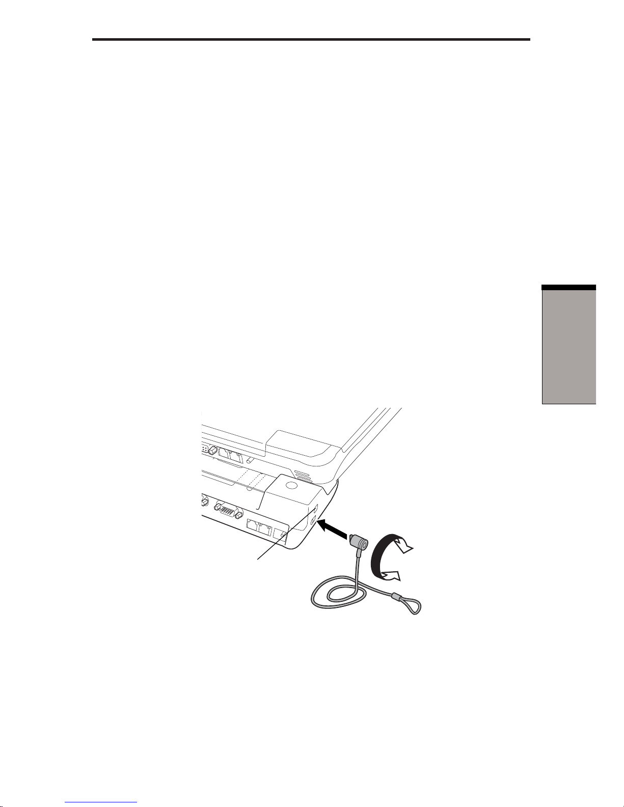
Security lock
A security lock enables you to anchor the Port Replicator to a desk or another
heavy object to help prevent unauthorized removal of the Port Replicator. A
computer lock can be set to engage the Port Replicator’s security lock so that the
computer cannot be disconnected from the Port Replicator while the security lock is
secured.
1. Attach one end of a cable to a desk or another heavy object.
2 . Set the computer lock.
NOTE: There are two positions for the computer lock.
Back: You can disconnect the computer from the Port Replicator.
Forward: You cannot disconnect the computer from the Port
Replicator.
3 . Insert the other end into the Port Replicator’s security lock slot.
4 . Secure it with the key.
Figure 3-6 Security lock
Security lock
COMPUTER LOCK

3-6
User’s Manual
CONNECTIONS

4-1
C
OMMUNICATIONS
Chapter 4
Communications
A jack enables easy connection to a local-area network without the need of a PC
card or other adaptor.
NOTE: When you use your computer with the Port Replicator connected
to it, do not attach any cables from external devices to your computer. If
these cables are connected to the ports of your computer, the ports of the
Port Replicator may not work as expected.
Modem
This section describes how to connect and disconnect a modem cable to the
modem jack.
For more information, refer to the computer's user manual and online help files.
CAUTIONS: 1. In case of a electric storm, unplug the modem cable from
the telephone jack.
2. Do not connect the modem to a digital telephone line.
A digital line will damage the modem.
Connecting
To connect the modem cable, follow the steps below.
1 . Plug one end of the modular cable into the modem jack.
2 . Plug the other end of the modular cable into a telephone jack.
Figure 4-1 Connecting the modem

4-2
User’s Manual
COMMUNICATIONS
Disconnecting
To disconnect the modem cable, follow the steps below.
1 . Pinch the lever on the connector in the telephone jack and pull out the
connector.
2 . Disconnect the cable from the Port Replicator in the same manner.
NOTE: If you use a storage device such as a CD-ROM drive or HDD
connected to a 16-bit PC Card, you might experience the following
modem problems:
1. Modem speed is slow or communication is interrupted.
2. Skips may occur in sound.
LAN
The Port Replicator supports Ethernet LAN, Fast Ethernet LAN and Gigabit
Ethernet LAN. If the computer does not support Gigabit Ethernet LAN (1000BASET), the Port Replicator supports only Ethernet LAN (10BASE-T) and Fast Ethernet
LAN (100BASE-Tx).
CAUTION: The computer must be configured properly before connecting to a LAN. Logging onto a LAN using the computer’s default settings
could cause a malfunction in LAN operation. Check with your LAN
administrator regarding set-up procedures.
If you are using Gigabit Ethernet LAN (1000 megabits per second, 1000BASE-T), be
sure to connect with a CAT5 cable or a CAT5E cable. (A CAT5E cable is recommended.) You cannot use a CAT3 cable.
If you are using Fast Ethernet LAN (100 megabits per second, 100BASE-TX), be
sure to connect with a CAT5 cable. You cannot use a CAT3 cable.
If you are using Ethernet LAN (10 megabits per second, 10BASE-T), you can
connect with either a CAT5 or a CAT3.
4-3
C
OMMUNICATIONS
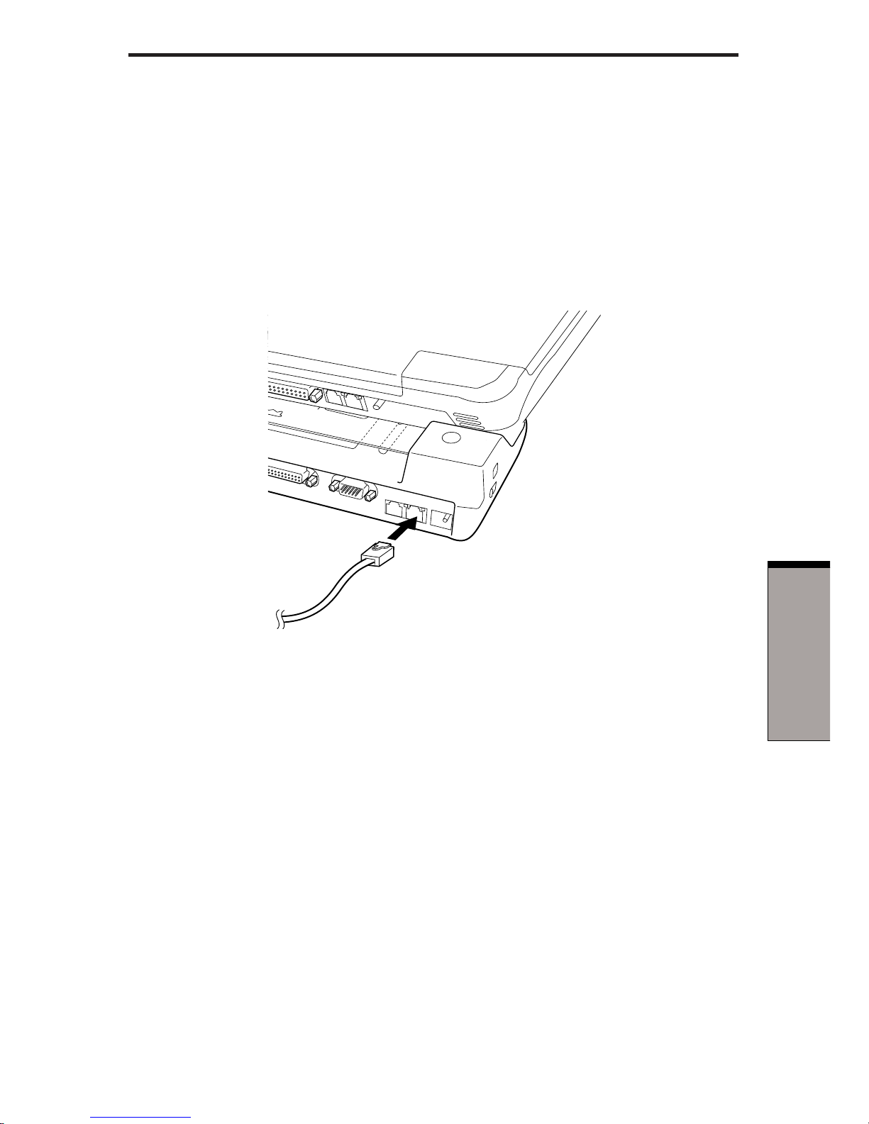
Connecting
To connect the LAN cable, follow the steps below.
1 . Save all your work. Turn off the power to the computer and to all external
devices connected to the Port Replicator and to the computer.
2 . Plug one end of the cable into the Port Replicator’s LAN jack. Press gently
until you hear the latch click into place.
Figure 4-2 Connecting the LAN cable
3 . Plug the other end of the cable into a LAN hub connector. Check with your
LAN administrator before connecting to a hub.
Disconnecting
To disconnect the LAN cable, follow the steps below.
CAUTION: Before you disconnect the LAN cable, make sure the computer is not accessing data. The green LED will glow when it is safe to
disconnect.
1 . Pinch the lever on the connector in the Port Replicator and pull out the
connector.
2 . Disconnect the cable from the LAN hub in the same manner. Check with your
LAN administrator before disconnecting from the hub.
LAN

4-4
User’s Manual
COMMUNICATIONS
Universal Serial Bus (USB 2.0) ports
A USB mouse, keyboard, and/or diskette connected to the Port Replicator via any
connection other than a first tier hub, will not work until the OS has started.
Using the USB diskette drive
A 3 1/2" diskette drive connects to the Port Replicator’s USB port. It accommodates
1.44-megabyte or 720-kilobyte diskettes.
Connecting the USB diskette drive
To connect the drive, plug the diskette drive connector into a USB port. Refer to
Figure 4-3.
NOTE: Make sure the connector is upside down and properly aligned
with the socket. Do not try to force the connection, doing so can damage
the connecting pins.
Figure 4-3 Connecting the USB diskette drive to the computer
NOTE: If you connect the diskette drive after turning on the computer, it
will take several seconds for the computer to recognize the drive. Do not
disconnect and reconnect before this time has elapsed.

4-5
C
OMMUNICATIONS
Disconnecting the USB diskette drive
When you have finished using the diskette drive, follow the procedures below to
disconnect it:
1 . Wait for the indicator light to go out to make sure all diskette activity has
stopped.
CAUTION: If you disconnect the diskette drive or turn off the power
while the computer is accessing the drive, you may lose data or damage
the diskette or the drive.
2 . Pull the diskette drive connector out of the USB port.
i.LINK (IEEE1394)
i.LINK (IEEE1394) is used for high-speed data transfer for a range of compatible
devices such as
❑ Digital video cameras
❑ Hard disk drives
❑ Optical disk drives
NOTE: i.LINK uses a four-pin connector, which does not carry electric
current. External devices will need their own power supply.
Precautions
❑ Make a back-up of your data before transferring it to the computer. There is a
possibility that the original data will be damaged. There is a particular risk that
some frames will be deleted in the case of digital video transfer.
❑ Do not transfer data in areas where static electricity is easily generated or in
areas subjected to electronic noise. Data can be destroyed.
❑ If you are transferring data through an IEEE1394 hub, do not connect or
disconnect other devices from the hub during data transfer. There is a likelihood that data will be damaged. Connect all devices to the hub before you turn
on the computer’s power.
i.LINK (IEEE1394)

4-6
User’s Manual
COMMUNICATIONS
Connecting
1 . Make sure the connectors are properly aligned and plug the i.LINK (IEEE1394)
cable into the computer.
Figure 4-4 Connecting the i.LINK cable
2 . Plug the other end of the cable into the device.
Note the following when you use i.LINK:
❑ You may need to install drivers for your i.LINK devices.
❑ Not all i.LINK devices have been tested, therefore, compatibility with all i.LINK
devices cannot be guaranteed.
❑ Use S100, S200 or S400 cables no longer than three meters.
❑ Some devices might not support standby or automatic-off functions.
❑ Do not connect or disconnect an i.LINK device while it is using an application
or when the computer is automatically shutting it down to save power. Data
might be destroyed.
Disconnecting
1 . Click the Unplug or Eject hardware icon on the Task Bar.
2. Select i.LINK (IEEE1394).
3 . When You can disconnect your i.LINK device appears, click
OK.
4 . Disconnect the cable from the computer, and then from the i.LINK device.
NOTE: Please also refer to your i.LINK device's documentation.

5-1
T
ROUBLESHOOTING
Chapter 5
Troubleshooting
This chapter provides tips to correct problems, should any occur. It also describes
how to contact TOSHIBA should you encounter problems that you cannot resolve.
Before you call Toshiba, please read the Before you call section in this chapter. Also
refer to the general troubleshooting advice at the beginning of the Troubleshooting
chapter in your computer's user manual.
If you can, add a cross-reference to the Before you call section.
NOTE: This chapter refers to the HW Setup diagnostic program. Some
computer models do not support all of these programs. Refer to your
computer's user manual.
Hardware checklist
This section discusses problems caused by your Port Replicator’s hardware. Basic
problems may occur in the following areas:
AC power
Power switch
Overheating power down
PS/2 keyboard
PS/2 mouse
Serial mouse
Printer
Monitor (External/DVI)
Sound system
USB
Modem
LAN
i.LINK (IEEE1394)

User’s Manual
5-2
TROUBLESHOOTING
AC power
If your computer is connected to the AC adaptor and you cannot turn on the
computer, check your computer's DC IN 15V indicator.
Problem Procedure
AC adaptor doesn’t Check the connections. Make sure the cord is
power the computer firmly connected to the computer and a power
(Your computer’s outlet.
DC IN 15V indicator
does not glow green)
Check the condition of the cord and terminals. If
the cord is frayed or damaged, replace it. If the
terminals are soiled, wipe them with cotton or a
clean cloth.
If the AC adaptor still does not power the
computer, contact your dealer.
Power switch
Problem Procedure
The computer does Connect the AC adaptor and try again to turn on
not turn on when the computer.
you press the
power switch If the computer still does not turn on, refer to the
sections
Overheating power down
and
AC
power
.

5-3
T
ROUBLESHOOTING
Overheating power down
If the computer’s internal temperature becomes too high, the computer will automatically enter Resume mode and shut down.
Problem Procedure
Computer enters Leave the computer off until its interior reaches
Resume mode and room temperature.
shuts down
If the computer has reached room temperature
and still does not start, or if it starts but shuts
down quickly, contact your dealer.
Computer shuts down Indicates a problem with the heat dispersal
and its DC IN 15V system. Please contact your dealer.
indicator is flashing
green
PS/2 keyboard
Keyboard problems can be caused by your setup configuration. For more information refer to your computer user’s manual.
Problem Procedure
No response from Make sure the keyboard cable is firmly connected
keyboard to the PS/2 keyboard port on the Port Replicator.
Output to screen Make sure the software you are using is not
is garbled remapping the keyboard. Remapping involves
reassigning the meaning of each key. See your
software’s documentation.
If you are still unable to use the keyboard,
contact your dealer.
Hardware checklist

User’s Manual
5-4
TROUBLESHOOTING
PS/2 mouse
Problem Procedure
No response from Make sure the PS/2 mouse cable’s 6-pin
PS/2 mouse connector is firmly connected to the PS/2 mouse
port on the Port Replicator.
On-screen pointer Verify that the PS/2 mouse cable’s 6-pin
does not respond to connector is firmly connected to the mouse
PS/2 mouse operation port.
You may have connected the mouse after
turning the computer on. Turn off the computer,
make sure the mouse is firmly connected and
turn the computer back on.
Is your software configured to recognize the
mouse? Check the software documentation.
If problems persist, contact your dealer.
Serial mouse
Problem Procedure
On-screen pointer Check for a firm connection between the
does not respond to Port Replicator’s serial port and the
serial mouse operation cable’s 9-pin connector.
Did you connect the mouse before turning on the
computer?
Is your software configured to recognize the
mouse? Check the software documentation.
If problems persist, contact your dealer.

5-5
T
ROUBLESHOOTING
Printer
Refer also to your computer user’s manual. Check the troubleshooting and other
relevant sections in your printer and software documentation.
Problem Procedure
Printer does not Check that the printer is connected to an electric
turn on. outlet. Make sure the outlet is supplying power.
Computer/printer Make sure the printer is turned on and is
do not communicate online (ready to use).
Inspect the cable connecting the printer to the
Port Replicator for damage. Make sure it is
securely connected.
A parallel printer connects to the parallel port and
a serial printer to the serial port. Make sure the
ports are configured correctly.
Make sure your software is configured to recognize the printer. Check your printer and software
documentation.
Printer error Check your printer documentation.
If problems persist, contact your dealer.
Hardware checklist

User’s Manual
5-6
TROUBLESHOOTING
Monitor (analog external monitor/DVI monitor)
Refer also to your computer user’s manual and to your monitor’s documentation.
Problem Procedure
Monitor does not Make sure that the monitor’s power switch is on.
turn on Confirm that the external monitor’s power cable is
plugged into a working power outlet.
No display Try adjusting the contrast and brightness controls
on the monitor.
Press hotkeys Fn + F5 to change the display
priority and make sure it is not set for the internal
display.
Display error occurs Check that the cable connecting the monitor to
the computer is attached firmly.
If problems persist, contact your dealer.

5-7
T
ROUBLESHOOTING
Sound system
Refer also to your computer user’s manual
Problem Procedure
No sound is heard Adjust the volume control dial.
Check the software volume settings.
Make sure the line-out connection is secure.
Check Windows Device Manager. Make sure the
sound function is enabled and that settings for
I/O address, Interrupt level and DMA are correct
for your software and do not conflict with other
hardware devices connected to the computer.
If problems persist, contact your dealer.
USB
Refer also to your USB device’s documentation.
Problem Procedure
USB device does Check for a firm cable connection between the
not work USB ports on the Port Replicator and the USB
device.
Make sure the USB device drivers are properly
installed. Refer to your Microsoft Windows
documentation for more information.
Hardware checklist

User’s Manual
5-8
TROUBLESHOOTING
If you are using an operating system that does
not support USB, you can still use a USB mouse
and/or USB keyboard. If these devices do not
work, make sure the USB Legacy Emulation
item in HW Setup is set to Enabled.
This feature works only for mouse and keyboard.
Also, Note that the mouse and keyboard must be
connected before you boot the computer.
A USB mouse, keyboard, and/or diskette connected to the Port Replicator via any connection
other than a first tier hub, will not work until the
OS has started.
If problems persist, contact your dealer.
Modem
Refer also to your computer user’s manual.
Problem Procedure
Communication Make sure the computer’s internal modem
software can’t settings are correct. Refer to
Modem
initialize modem Properties in the Control Panel.
You can hear a dial If the call is going through a PBX machine, make
tone but can’t make sure the communication application’s tone dial
a call detection feature is disabled.
You can also use the ATX command. Refer to
the material on AT commands in the computer's
user manual or online Help.

5-9
T
ROUBLESHOOTING
You place a call, Make sure the settings are correct in your
but a connection communications application.
can’t be made
After making a call, Make sure the tone or pulse selection in your
you don’t hear a ring communications application is set correctly.
You can also use the ATD command. Refer to
the material on AT commands in the computer's
user manual or online Help.
Communication is The computer will automatically cut off
cut off unexpectedly communication when connection with the carrier
is not successful within a set time interval. Try
lengthening this time interval.
A CONNECT display Check the error control setting in your
is quickly replaced by communications application.
NO CARRIER
You can also use the AT\N command. Refer to
the material on AT commands in the computer's
user manual or online Help.
Character display In data transmission, make sure the parity bit
becomes garbled and stop bit settings correspond with those
during a of the remote computer.
communication
Check the flow control and communication
protocol.
You cannot receive Check the rings before auto answer setting in
an incoming call your communications application.
You can also use the ATS0 command. Refer to
the material on S-registers in the computer's user
manual or online Help.
If problems persist, contact your dealer.
Hardware checklist

User’s Manual
5-10
TROUBLESHOOTING
LAN
Problem Procedure
Cannot access LAN Contact the system administrator or if the
problem persists, contact your dealer.
i.LINK (IEEE1394)
Problem Procedure
i.LINK device does Make sure the cable is securely connected to
not function the computer and to the device.
Make sure the device’s power is turned on.
Reinstall the drivers. Open the Windows Control
Panel and double-click the Add New Hardware
icon. Follow the on-screen directions.
Restart Windows.
If problems persist, contact your dealer.

5-11
T
ROUBLESHOOTING
TOSHIBA support
TOSHIBA support
If you require any additional help using your computer or if you are having problems
operating the Port Replicator, you may need to contact TOSHIBA for additional
technical assistance.
Before you call
Some problems that you experience may be related to software or the operating
system. Before you contact TOSHIBA, please investigate your problem using the
following resources:
Review troubleshooting sections in the documentation for your computer,
software and peripheral devices.
If a problem occurs when you are running software applications, consult the
software documentation for troubleshooting suggestions. Call the software
company’s technical support for assistance.
Consult the dealer you purchased your computer and/or software from. They
are your best sources for current information and support.
Where to write
If you are still unable to solve the problem and suspect that it is hardware related,
write to TOSHIBA at the nearest location listed on the next page.

User’s Manual
5-12
TROUBLESHOOTING
Outside of Europe
Australia
TOSHIBA Australia Pty. Ltd.
Information Systems Division
84-92 Talavera Road
North Ryde N.S.W. 2113
Sydney
Canada
TOSHIBA of Canada Ltd.
191 McNabb Street,
Markham, Ontario
L3R 8H2
China
TOSHIBA Computer Systems (Shanghai) Co., Ltd.
Bldg 33, No.351, Jinzang Road,
Pudong New Area, Shanghai,
P.R.China 201206
Singapore
TOSHIBA Singapore Pte. Ltd.
460 Alexandra Road
#25-06 PSA Building
Singapore 119963
United States of America
TOSHIBA America Information
Systems, Inc.
9740 Irvine Boulevard
Irvine, California 92718
USA
In Europe
Federal Republic of Germany
TOSHIBA Europe (I.E.) GmbH
Geschäftsbereich,
Deutschland-Österreich
Hammfelddamm 8,
D-41460 Neuss
France
TOSHIBA Systèms France S.A.
7, Rue Ampère,
92804 Puteaux Cedex
Netherlands
TOSHIBA Information Systems,
Benelux B.V.
Rivium Boulevard
41 2909 LK Capelle a/d IJssel
Spain
TOSHIBA Information Systems,
Parque Empresarial San Fernando
Edificio Europa, la planta,
Escalera A 28831 Madrid
United Kingdom
TOSHIBA Information Systems (U.K.)
Ltd.
TOSHIBA Court
Weybridge Business Park
Addlestone Road
Weybridge, Surrey KT15 2UL
The Rest of Europe
TOSHIBA Europe (I.E.) GmbH
Geschäftsbereich,
Deutschland-Österreich
Hammfelddamm 8,
D-41460 Neuss

A-1
A
PPENDIX
A
Appendix A
Specifications
This appendix summarizes the Port Replicator’s technical specifications.
Physical Dimensions
Weight 1023 grams
Size 356 (w) x 54 (h) x 160 (d) millimeters
Environmental Requirements
Ambient Relative
Conditions temperature humidity
Operating 5°C (41°F) to 35°C (95°F) 20% to 80%
Non-operating -20°C (-4°F) to 65°C (149°F) 10% to 95%
Thermal Gradient 20°C per hour maximum
Wet-bulb temperature 26°C maximum
Conditions Altitude (from sea level)
Operating -60 to 3,000 meters
Non-operating -60 to 10,000 meters maximum
Power Requirements
AC adaptor 100 - 240 volts AC
50 or 60 hertz (cycles per second)
15 VDC
5.0 amperes

A-2
User’s Manual
APPENDIX A

B-1
A
PPENDIX
B
Appendix B
AC Power Cord and
Connectors
The power cord’s AC input plug must be compatible with the various international
AC power outlets and the cord must meet the standards for the country/region in
which it is used. All cords must meet the following specifications:
Length: Minimum 2 meters
Wire size: Minimum 0.75 mm
2
Current rating: Minimum 2.5 amperes
Voltage rating: 125 or 250 VAC
(depending on country/region’s power standards)
Certification agencies
U.S. and Canada: UL listed and CSA certified
No. 18 AWG, Type SVT or SPT-2 two conductor
Europe:
Austria: OVE Italy: IMQ
Belgium: CEBEC The Netherlands: KEMA
Denmark: DEMKO Norway: NEMKO
Finland: SETI Sweden: SEMKO
France: UTE Switzerland: SEV
Germany: VDE United Kingdom: BSI
Australia: AS
Japan: DENANHO
In Europe, power cords must be VDE type, H05VVH2-F and two conductor.
For the United States and Canada, plug configuration must be a 2-15P (250 V) or 1-
15P (125 V) as designated in the U.S. National Electrical code handbook and the
Canadian Electrical Code Part II.
B-2
User's Manual
APPENDIX B
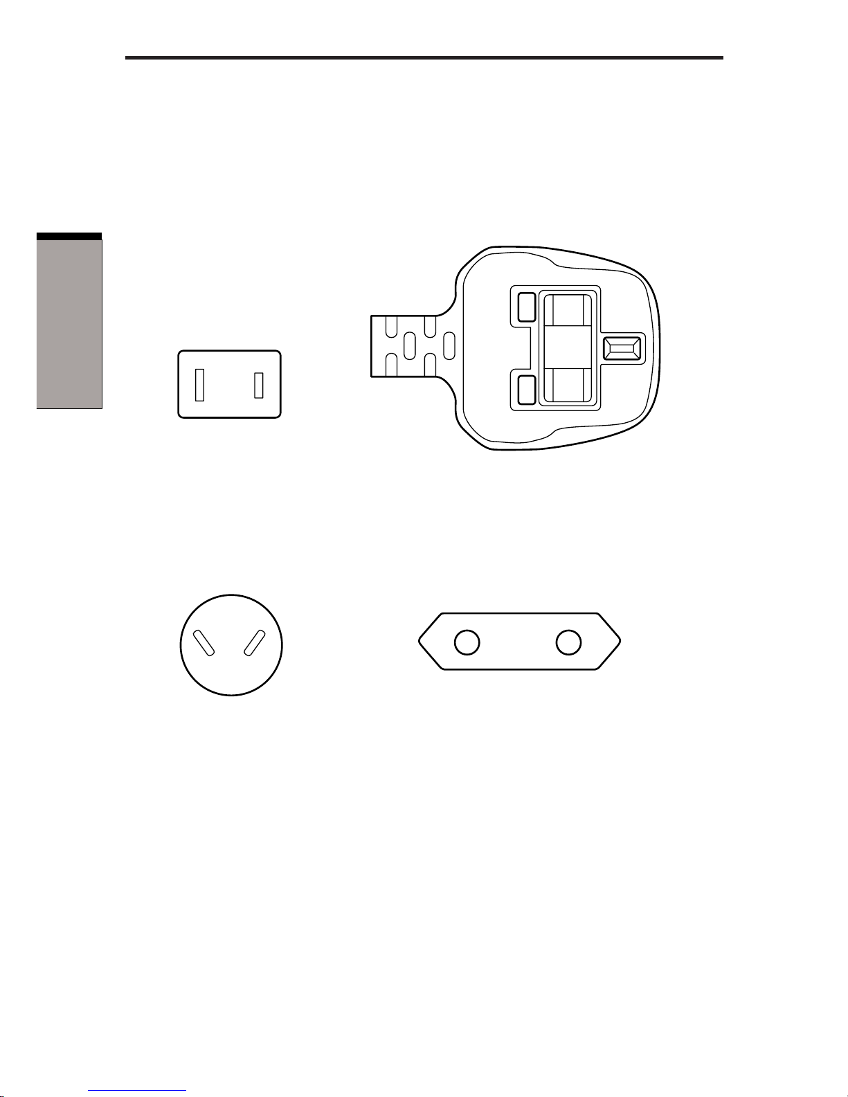
The following illustrations show the plug shapes for the U.S.A. and Canada, the
United Kingdom, Australia and Europe.
USA and Canada United Kingdom
Australia Europe
BS approved
UL approved
CSA approved
AS approved
Approved by the
appropriate agency

Index-1
I
NDEX
Index
A
AC adaptor
specifications 1-1, 2-5
connecting 3-3
connectors location 2-3
C
CAT3 CAT5 CAT5E cables 4-2
Center mark 2-2
location 2-1
Computer connection
port location 2-1
Computer lock 1-3
location 2-3
using 3-5
D
DC-IN 15V 2-5
location 2-3
DVI 1-2
port location 2-3
E
Eject switch 2-2
Eject LED 2-2
Eject lever 2-2
Equipment checklist 1-1
Ethernet 1-2, 4-2
F
Fast Ethernet, see Ethernet
G
Gigabit Ethernet, see Ethernet
H
Hardware checklist, see Trouble-
shooting
I
i.LINK 1-2, 4-5
connecting 4-6
disconnecting 4-6
port location 2-3
precautions 4-5
problems, see Troubleshooting
K
Keyboard
PS/2 keyboard port 2-3
problems, see Troubleshooting
L
LAN 1-2
connecting 4-3
disconnecting 4-3
Ethernet usage 4-2
features 4-2
jack location 2-3
problems, see Troubleshooting
using 4-2
M
Modem 1-2
connecting 4-1
disconnecting 4-2
jack location 2-3
problems, see Troubleshooting
using 4-1

Index-2
User's Manual
INDEX
Monitor external 2-4
port location 2-3
problems, see Troubleshooting
Mouse
PS/2 mouse port location 2-3
PS/2 mouse problems, see
Troubleshooting
serial mouse problems, see
Troubleshooting
P
Parallel port 1-2, 2-4
Port Replicator
connecting 3-1
disconnecting 3-4
PS/2, see keyboard or mouse
Printer, see Parallel port and Trouble-
shooting
S
Security lock slot 1-3, 2-5
location 2-3
using 3-5
Serial port 1-2
location 2-3
problems, see Troubleshooting
Sound system
jacks
line-in 1-2, 2-3
line-out 1-2, 2-3
problems, see Troubleshooting
T
TOSHIBA support 5-11
Troubleshooting
AC power 5-2
hardware checklist 5-1
i.LINK 5-10
LAN 5-10
modem 5-8
monitor 5-6
overheating power down 5-3
power switch 5-2
printer 5-5
PS/2 keyboard 5-3
PS/2 mouse 5-4
serial mouse 5-4
sound system 5-7
USB 5-7
U
Universal Serial Bus 1-2, 4-4
location 2-3
problems, see Troubleshooting
 Loading...