

Page 1

TOSHIBA Telecommunication Systems Division
General Description
Title Page
January 2012
Page 2

Publication Information
Toshiba America Information Systems, Inc.
Telecommunication Systems Division
Publication Information
Toshiba America Information Syste ms, Inc., Telecommunication Systems Division, reserves the right,
without prior notice, to revise this information publication for any reason, including, but not limited to,
utilization of new advances in the state of technical arts or to simply change the design of this document.
Further, Toshiba America Information Systems, Inc., Telecommunication Systems Division, also reserves
the right, without prior notice, to make such changes in equipment design or compone nts as engine ering or
manufacturing methods may warrant.
IPe-GD-ALL-VE
Version E, January 2012
4010488
Our mission to publish accurate, complete and user accessible documentation. At the time of printing the
information in this document was as accurate and current as was reasonably possible. However, in the
time required to print and distribute this manual additions, corrections or other changes may have been
made. To view the latest version of this or other documents please refer to the Toshiba FYI web site.
Toshiba America Information Systems shall not be liable for any commercial losses, loss of revenues or
profits, loss of goodwill, inconvenience, or exemplary, special, incidental, indirect or consequential
damages whatsoever , or claims of third parties, regar dless of the form of any claim that may re sult from the
use of this document.
THE SPECIFICATIONS AND INFORMATION PROVIDED HEREIN ARE FOR INFORMATIONAL
PURPOSES ONLY AND ARE NOT A WARRANTY OF ACTUAL PERFORMANCE, WHETHER
EXPRESSED OR IMPLIED. THE SPECIFICATIONS AND INFORMATION ARE SUBJECT TO CHANGE
WITHOUT NOTICE. ACTUAL PERFORMANCE MAY VARY BASED ON INDIVIDUAL
CONFIGURATIONS, USE OF COLLA TERAL EQUIPMENT, OR OTHER FACTORS.
© Copyright 2011~2012
This document is copyrighted by Toshiba America Information Systems, Inc. with all rights reserved. Under
the copyright laws, this document cannot be reproduce d in any form or by any means—graphic, ele ctronic,
or mechanical, including recording, taping, photocopying, without prior written permission of Toshiba. No
patent liability is assumed, however, with respect to the use of the information contained herein.
Trademarks
Toshiba, IPedge, CIX, SoftIPT and Strata are trademarks of Toshiba Corporation or Toshiba America
Information Systems, Inc.
Appcritical is a registered trademark of Apparent Networks, Inc.
Linux is a registered trademark of Linus Torvald.
AudioCodes is Registered trademark of AudioCodes Ltd.
Cisco is a registered trademark of Cisco Technology, Inc.
Mac is a registered trademark of Apple Computer, Inc.
SonicWALL is a registered trademark of SonicWALL, Inc.
Mozilla and Firefox are registered trademarks of Mozilla Foundation Corp.
Windows, Outlook, and Microsoft are registered trademarks of Microsoft.
Zenoss is a registered trademark of Zenoss, Inc.
Trademarks, registered trademarks, and service marks are the property of their respective owners.
Page 3

IPedge General End User Information
FCC Requirements
Means of Connection: The IPedge does not connect directly to the telephone network. All direct
connections are made to a gateway. Please refer to the gateway manufacturer's documentation
Radio Frequency Interference
Warning: This equipme nt gene ra te s, u ses, and ca n r adi ate r adio fre quency en er gy and if n ot installed and
used in accordance with the manufacturer’s instruction manual, may cause interference to radio
communications. It has been tested and fo un d to comply with the limits for a Class A computing device
pursuant to Subpart J of Part 15 of FCC Rules, which are designed to provide reasonable protection
against such interference when operated in a commercial environment. Operation of this equipment in a
residential area is likely to cause interference, in which case, the user, at his/her own expense, will be
required to take whatever measures may be required to correct the interference.
Underwriters Laboratory
This system is listed with Underwriters Laboratory (UL). Secondary protection is required, on
any wiring from any telephone that exits the b uilding or is subject to ligh tning or other electrical
surges, and on DID, OPS, and Tie lines. (Additional information is provided in the IPedge
Install Manual.)
CP01, Issue 8, Part I Section 14.1
Notice: The Industry Canada label identifies certified equipment. This certification means that the
equipment meets certain telecommunications network protective, operational and safety requirements as
prescribed in the appropriate Terminal Equipment Technical Requirements document(s). The Department
does not guarantee the Equipment will operate to the user’s satisfaction.
Repairs to Certified Equipment should be coordinated by a representative designated by the supplier.
Any repairs or alterations made by the user to this equipment, or equipment malfunctions, may give the
telecommunications company cause to request the user to disconnect the equipment.
301756
I.T.E
Users should ensure for their own protection that the electrical ground connections of the power utility,
telephone lines and internal metallic water pipe system, if present, are connected together. This precaution
may be particularly important in rural areas.
Before installing this equipment, users should ensure that it is permissible to be connected to the facilities
of the local telecommunications company. The equipment must also be installed using an acceptable
method of connection. The customer should be aware that complia nce with the above conditions may not
prevent degradation of service in some situ atio n s.
CAUTION! Users should not attempt to make such connections themselves, but should
contact the appropriate electric inspection authority, or electrician, as appropriate.
Important Notice — Music-On-Hold
In accordance with U.S. Copyright Law, a license may be required from the American Society of
Composers, Authors and Publishers, or other similar organization, if radio or TV broadcasts are
transmitted through the music-on-hold feature of this telecommunication system. Toshiba America
Information Systems, Inc., strongly recommends not using radio or television broadcasts an d hereby
disclaims any liability arising out of the failure to obtain such a license.
Hearing Aid Compatibility Notice: The FCC has established rules that require all installed business
telephones be hearing aid compatible. This rule applies to all telephones regardless of the date of
manufacture or installation. There are severe financial penalties which may be levied on the end-user for
non-compliance.
Page 4

Patent Marking for G.729a
Products may be covered by one or more of the following US patents and their counterparts in other
countries:
US5,787,391, US5,717,825, US5,708,757, US5,754,976, US5,701,392, US5,699,482, US5,444,816
MPEG-4 VISUAL PATENT PORTFOLIO LICENSE (for VCS)
“THIS PRODUCT IS LICENSED UNDER THE MPEG-4 VISUAL PATENT PORTFOLIO LICENSE FOR
THE PERSONAL AND NON-COMMERCIAL USE OF A CONSUMER FOR (i)ENCODING VIDEO IN
COMPLIANCE WITH THE MPEG-4 VISUAL STANDARD (“MPEG-4 VIDEO”) AND/OR (ii)DECODING
MPEG-4 VIDEO THAT WAS ENCODED BY A CONSUMER ENGAGED IN A PERSONAL AND NONCOMMERCIAL ACTIVITY AND/OR WAS OBTAINED FROM A VIDEO PROVIDER LICENSED BY MPEG
LA TO PROVIDE MPEG-4 VIDEO. NO LICENSE IS GRANTED OR SHALL BE IMPLIED FOR ANY
OTHER USE. ADDITIONAL INFORMATION INCLUDING THAT RELATING TO PROMOTIONAL,
INTERNAL AND COMMERCIAL USES AND LICENSING MAY BE OBTAINED FROM MPEG LA,L.L.C.
SEE HTTP://WWW.MPEGLA.COM”
Toshiba America Information Systems, Inc.
Telecommunication Systems Division, End User License Agreement
Refer to “End User License Agreement” on page 115
Toshiba America Information Systems, Inc.
Telecommunication Systems Division, End User Standard User Limited Warranty
Refer to “End User Standard Limited Warranty” on page 121
Toshiba America Information Systems, Inc.
Telecommunication Systems Division, Redistribution of OpenSource GPL Attribution
Refer to Toshiba Internet FYI > IPedge > Documentation.
Page 5

WARRANTIES FOR NON-TOSHIBA BRANDED THIRD
PARTY PRODUCTS
A valuable element of Toshiba’ s product strategy is to offer our customers a complete product portfolio. To
provide this value to our customers at the most optimal prices, we offer both Toshiba-branded and thirdparty manufactured products that support our Toshiba IPedge and Strata CIX product portfolio. Similar to
other resellers of software, hardware and peripherals, these third-party manufactured products carry
warranties independent of our Toshiba limited warranty provided with our Toshiba-branded products.
Customers should note that third-party manufacturer warranties vary from product to product and are
covered by the warranties provided through the original manufacturer and passed on intact to the
purchaser by Toshiba. Customers should consult their product documentation for third-party warranty
information specific to third-party products. Mo re information may also be a vailable in some cases fr om the
manufacturer’s public website.
While Toshiba offers a wide selection of software, hardware and peripheral products, we do not specifically
test or guarantee that the third-party product s we of fer work under e very configuration with any o r all of the
various models of the Toshiba IPedge or Strata CIX system. Toshiba does not endorse, warrant nor
assume any liability in connection with such third party products or services. If you have questions about
compatibility, we recommend and encourage you to contact the third-party software, hardware and
peripheral product manufacturer directly.
Page 6

This page is intentionally left blank.
Page 7

Content s
Introduction
Organization ........................................................................................................................................ xv
Conventions ........................................................................................................................................ xvi
Related Documents/Media ................................................................................................................. xvi
Chapter 1 – Overview
IPedge Solutions .................................................................................................................................... 3
Other Advantages .................................................................................................................................. 4
Operating Environment ......................................................................................................................... 5
Software ................................................................................................................................................ 5
Deployment ........................................................................................................................................... 5
Administration ....................................................................................................................................... 6
Unified System Administration ............................................................................................................. 6
Configuration ........................................................................................................................................ 7
Software Support and Upgrade Service ................................................................................................ 9
Chapter 2 – Telephones and Peripherals
IP 5000-Series IP Telephones ............................................................................................................. 11
Features ......................................................................................................................................... 13
Connectivity .................................................................................................................................. 13
Capabilities ................................................................................................................................... 14
Liquid Crystal Display (LCD) Models ......................................................................................... 15
IP4100 DECT Telephone .................................................................................................................... 16
Handset Features ........................................................................................................................... 16
IP4100-BASE Features ................................................................................................................. 16
Telephone Button Expansion Options ................................................................................................ 17
LCD Add-on Module (LM5110) .................................................................................................. 17
Key Module (KM5020) ................................................................................................................ 17
IP Direct Station Selection (IDM5060) Console .......................................................................... 17
Attendant Console ............................................................................................................................... 18
Peripherals ........................................................................................................................................... 20
Polycom End Points ...................................................................................................................... 20
CyberData ..................................................................................................................................... 21
Gateways ...................................................................................................................................... 22
Chapter 3 – Unified Communications
IPedge Messaging ............................................................................................................................... 28
Follow-Me .................................................................................................................................... 28
Unified Messaging ........................................................................................................................ 28
IPedge General Description 01/12 vii
Page 8

Contents
Chapter 4 – Networking
Other Messaging Features ............................................................................................................ 28
Call Manager ....................................................................................................................................... 29
Call Manager Standard ................................................................................................................. 29
Call Manager Advanced ............................................................................................................... 30
Companion Applications .............................................................................................................. 31
Meeting ............................................................................................................................................... 33
Audio Conference Features ................................................................................... ....................... 33
Web Collaboration Features ......................................................................................................... 33
Mobility ............................................................................................................................................... 34
uMobility Fixed Mobile Convergence (FMC) ............................................................................. 34
Wireless Telephones ..................................................................... ...................................................... 35
IP User Mobility ................................................................................ .................................................. 35
SoftIPT Client ............................................................................................................................... 37
Chapter 4 – Networking
Preplanning for VoIP Deployment ...................................................................................................... 39
Benefits ......................................................................................................................................... 39
Requirements ................................................................................................................................ 39
Interactions ................................................................................................................................... 40
LAN Deployment ................................................................................................................................ 41
Benefits ......................................................................................................................................... 41
Requirements ................................................................................................................................ 41
Interactions ................................................................................................................................... 42
Remote Administration ....................................................................................................................... 43
Benefits ......................................................................................................................................... 43
Requirements ................................................................................................................................ 43
Interactions ................................................................................................................................... 43
Centralized Administration ................................................................................................................. 44
Benefits ......................................................................................................................................... 44
Requirements ................................................................................................................................ 44
Interactions ................................................................................................................................... 44
IPedge Net ........................................................................................................................................... 44
Benefits ......................................................................................................................................... 44
Requirements ................................................................................................................................ 44
Interactions ................................................................................................................................... 44
Remote IP Telephones ........................................................................................................................ 45
Benefits ......................................................................................................................................... 45
Requirements ................................................................................................................................ 45
Interactions ................................................................................................................................... 45
Remote SIP Phones ............................................................................................................................. 46
Benefits ......................................................................................................................................... 46
Requirements ................................................................................................................................ 46
Interactions ................................................................................................................................... 46
SIP Trunking ....................................................................................................................................... 47
Benefits ......................................................................................................................................... 47
Requirements ................................................................................................................................ 47
Interactions ................................................................................................................................... 47
Web Conferencing .............................................................................................................................. 48
Benefits ......................................................................................................................................... 48
viii IPedge General Description 01/12
Page 9

Contents
Chapter 5 – Contact Center
Requirements ................................................................................................................................ 48
Interactions ................................................................................................................................... 48
Chapter 5 – Contact Center
Basic ACD Features .......................................................................... ..... .... ......................................... 49
Advanced Call Routing ................................................................................................................ 49
Intelligent Announcements ........................................................................................................... 49
IVR Voice Assistant Open Database Connectivity (ODBC) Access ........................................... 49
Enhanced ACD Features ..................................................................................................................... 50
Agent Priority Routing ................................................................................................................. 50
Multiple Group Agent Login ........................................................................................................ 50
Skills-based Routing ..................................................................................................................... 50
Priority Queuing ........................................................................................................................... 50
Web-based Contact Center .................................................................................................................. 50
Web Callback ............................................................................................................................... 50
Chat Contact Center ...................................................................................................................... 50
Chapter 6 – Features
Account Codes .................................................................................................................................... 51
Add-on Module (ADM) ...................................................................................................................... 51
Advisory Message ............................................................................................................................... 51
Alarm Notification ................................................................................. ............................................. 52
Alternate Answer Point ....................................................................................................................... 52
Automatic Busy Redial ....................................................................................................................... 52
Automatic Call Distribution (ACD) Server ........................................................................................ 52
Automatic Callback (ACB) ................................................................................................................. 52
Automatic Line Selection (ALS) ........................................................................................................ 52
Background Music (BGM) ................................................................................................................. 53
Call Completion .................................................................................................................................. 53
Call Forward ........................................................................................................................................ 53
Call History ......................................................................................................................................... 54
Call Manager ....................................................................................................................................... 54
Call Park .............................................................................................................................................. 54
Call Pickup .......................................................................................................................................... 55
Call Transfer ........................................................................................................................................ 55
Call Waiting ........................................................................................................................................ 57
Caller Identification ............................................................................................................................ 57
Class of Service .................................................. .... ..... ................................................... ..................... 58
Conference Call ................................................................................................................................... 58
Credit Card Calling .................................................................................... ......................................... 59
Day/Night Mode .................................................................................................................................. 60
Dial Directory ...................................................................................................................................... 61
Direct Inward Dialing (DID) ............................................................................................................... 61
Dialed Number Identification Service (DNIS) ................................................................................... 61
Directory Numbers .............................................................................................................................. 62
Direct Station Selection (DSS) ............................................................................................................ 63
Distinctive LED Indicator ................................................................................................................... 63
Distinctive Ringing ............................................................................................................................. 64
Do Not Disturb (DND) ........................................................................................................................ 64
ix IPedge General Description 01/12
Page 10

Contents
Chapter 6 – Features
Emergency Call .................................................................... .... ..... ...................................................... 64
Enhanced 911 (E911) .......................................................................................................................... 64
Feature Prompting With Soft Keys ..................................................................................................... 65
Flexible Line Ringing ......................................................................................................................... 65
Flexible Numbering ............................................................................................................................ 65
Handsfree Answerback ....................................................................................................................... 65
Headset ................................................................................................................................................ 65
Hearing Aid Compatible .......................................................................................... .... ..... .................. 66
High Call Volume Buttons .................................................................................................................. 66
Hold ..................................................................................................................................................... 66
Automatic Hold ............................................................................................................................ 66
Call Hold ....................................................................................................................................... 66
Consultation Hold ......................................................................................................................... 66
Exclusive Hold ............................................................................................................................. 66
Hold Recall ................................................................................................................................... 66
Hot Dialing .......................................................................................................................................... 67
Hotline Service .................................................................................................................................... 67
IPedge Net ........................................................................................................................................... 67
Line Buttons ........................................................................................................................................ 68
Pooled CO Line Button ........ ..... .... ............................................................................................... 68
Group CO Line Button ................................................................................................................. 68
Live System Programming .................................................................................................................. 68
Meeting ............................................................................................................................................... 68
Message Waiting ................................................................................................................................. 68
Mobility ............................................................................................................................................... 69
Music/Messaging On Hold ................................................................................................................. 69
Multiple Call/Delayed Ringing ......................................................................................... .... .............. 69
Off-hook Camp On ............................................................................................................................. 70
Override ............................................................................................................................................... 70
Call Forward Override .................................................................................................................. 70
Class Of Service Override ............................................................... ............................................. 70
Do Not Disturb (DND) Override .................................................................................................. 70
Executive Override ....................................................................................................................... 71
Privacy Override ........................................................................................................................... 71
Paging .................................................................................................................................................. 71
Telephone Group Paging .............................................................................................................. 71
Emergency Page ....................................................................................... .................................... 71
External Paging ............................................................................................................................. 72
Power Failure Protection ..................................................................................................................... 72
Reserve Power Battery Backup .................................................................................................... 72
Privacy ................................................................................................................................................. 72
Remote Update .................................................................................................................................... 72
Repeat Last Number Dialed .....................................................................................................
Ringing ................................................................................................................................................ 73
Speed Dial ........................................................................................................................................... 74
One Touch Buttons ....................................................................................................................... 74
Station Hunting ................................................................................................................................... 75
Serial Hunting ............................................................................................................................... 75
Circular Hunting ........................................................................................................................... 75
Distributed Hunting ...................................................................................................................... 75
........... 72
x IPedge General Description 01/12
Page 11

Contents
Appendix – Specifications
Camp on to Hunt Groups .............................................................................................................. 75
Station Message Detail Recording (SMDR) ....................................................................................... 76
Survivability ........................................................................................................................................ 76
System Fault Finding and Diagnostics ................................................................................................ 77
Alarm Indication of System Faults ............................................................................................... 77
Fault Detection and Error Logs .................................................................................................... 77
Event and System Administration Logs ....................................................................................... 77
Automatic Fault Recovery ............................................................................................................ 77
Backup and Restore ...................................................................................................................... 77
Maintenance and Administration .................................................................................................. 77
Software Upgrade ......................................................................................................................... 77
Tenant Services ................................................................................................................................... 78
Traffic Measurement ........................................................................................................................... 78
Transfer Direct To Voice Mail ............................................................................................................ 79
Uniform Call Distribution ................................................................................................................... 80
Unified Communications .................................................................................................................... 80
VLAN Tagging ................................................................................................................................... 81
Voice / Tone Signaling ........................................................................................................................ 81
Volume Control ................................................................................................................................... 82
Messaging ........................................................................................................................................... 82
Automated Attendant .................................................................................................................... 82
Fax ................................................................................................................................................ 84
Voice Messaging .......................................................................................................................... 85
Unified Messaging ........................................................................................................................ 90
Multi-site Networking .................................................................................................................. 91
Administration .............................................................................................................................. 91
Reporting ...................................................................................................................................... 93
Security ......................................................................................................................................... 95
Appendix – Specifications
Operating Environment. ...................................................................................................................... 97
Power Considerations .......................................................................................................................... 98
UPS Recommendation .................................................................................. ..... .... ....................... 98
Station Dimensions ............................................................................................................................. 98
IPedge Component Compatibility ....................................................................................................... 99
System Tones ............................................................................................................................. ....... 100
IPedge Net and IP Telephone Bandwidth Requirements .................................................................. 103
Capacities .......................................................................................................................................... 105
Application Capacities ................................................................................................................ 108
Device Monitor Capacities for IPedge Systems ......................................................................... 109
IPedge Software License Requirements ............................................................................................ 110
Audiocodes Parts ............................................................................... ................................................ 114
End User License Agreement.................................................................................. 117
End User Standard Limited Warranty..................................................................... 123
Index
....................................................................................................................................................... 127
IPedge General Description 01/12 xi
Page 12

This page is intentionally left blank.
Page 13

Introduction
This General Description provides an overview of the IPedge business telephone systems,
associated hardware, features, capabilities, and capacities. The features described in this document
assume that the IPedge system has the current software release installed.
Organization
This document is divided into the following major topics:
• Chapter 1 – Overview is a brief introduction of the IPedge system, environmental and power
considerations, related software, administration, configuration, and network requirements.
• Chapter 2 – Telephones and Peripherals describes the most recent Toshiba-proprietary
stations and peripherals, customer-supplied peripherals, as well as cabling and connectors.
• Chapter 3 – Unified Communications describes the IPedge Messaging, Call Manager,
Meeting, and Mobility Solutions which together form Toshiba’s Unified Communications
product suite.
• Chapter 4 – Networking describes the various network related configurations that need to be
done when installing the IPedge system.
• Chapter 5 – Contact Center describes the ACD software that resides on the MAS, its basic
capacities, system expansion, and remote maintenance.
• Chapter 6 – Features describes the features which are available system-wide, as well as
stations features.
• Appendix – Specifications includes detailed information on network requirements, station
dimensions, system tones, hardware compatibility, software license requirements, and
capacities.
IPedge General Description 01/12 xiii
Page 14

Introduction
Conventions
Conventions
Conventions Description
Elaborates specific items or references other information. Within
Note
some tables, general notes apply to the entire table and numbered
notes apply to specific items.
Important!
Courier Shows a computer keyboard entry or screen display.
“Type” Indicates entry of a string of text.
“Press”
Plus (+)
Tilde (~) Means “through.” Example: 350 ~ 640 Hz frequency range.
Start > Settings > Printers Denotes a progression of buttons and/or menu options on the
See Figure 10
Calls attention to important instructions or information.
Indicates entry of a single key. For example: Type prog then
press Enter.
Shows a multiple PC keyboard or telephone button entry. Entries
without spaces between them show a simultaneous entry.
Example: Esc+Enter. Entries with spaces between them show a
sequential entry. Example:
screen you should select.
Grey/Blue words within the printed text denote cross-references.
In the electronic version of this document (Library CD-ROM or
FYI Internet download), cross-references appear in blue hypertext.
Related Documents/Media
# 5.
Installation and Programming Manuals
•IPedge Installation
•IPedge Feature Description and Implementation
User Guides
•IPedge Telephone, Messaging, and Call Manager
Quick Reference Guide
•IPedge IP5000-Series Telephone
Internet Site
For authorized users, Internet site FYI (http://fyi.tsd.toshiba.com) contains all current IPedge
documentation and enables you to view, print and download current publications.
xiv IPedge General Description 01/12
Page 15

Overview 1
EC Server
EC Server
Figure 1 IPedge EC and EM Servers
Bezel (Optional)
EM Server
The IPedgeTM system is an advanced pure IP platform that provide sophisticated business
communication features. The IPedge system performs call processing, voice mail, unified
messaging, media processing that includes conferencing and paging, meet-me conferencing with
web collaboration, centralized management, Call Manager unified communications, and more.
IPedge uses Red Hat Enterprise Linux 5.4 for the base operating system that provides a high level
of scalability and security.
IPedge is a software centric Unified Communications platform designed for customers who want
to deploy on an all IP network infrastructure to realize the savings of managing a single network.
Networking between IPedge servers and/or Strata CIX systems is enabled via IPedge Net using
one IP address.
The IPedge solution is easy to install and is available in three different sizes depending on the
number of users, applications, and conferencing needs. The EP server supports 8 to 40 users, the
EC server supports applications up to 200 users and the EM server supports up to 1,000 users.
IPedge can also connect to a MAS or MicroMAS via IP to run ACD and it can connect to
uMobility and other external applications.
IPedge General Description 01/12 1
Page 16

Overview
Figure 2 IPedge EP Server
IPedge EP System (Horizontal view
with Left and Right Rack-mount Brackets)
IPedge EP System
(Horizontal and Vertical view)
Table 1 Basic Specifications
EC Server EM Server EP Server
Rackmount Rackmount Stand alone or 19” Rackmount
1U; 15” Deep; 19” Wide 1U; 25.6” Deep; 19” Wide
1 x Core 2 Quad x 2.6GHz
Processor, 4GB DRAM
1 x 160GB HDD
Up to 200 Users Up to 1,000 Users 8 to 40 Users
2 x Quad Core x 2GHz Xeon
Processors,12GB DRAM
2 x 300GB HDDs
(RAID 1 standard)
1.75U or 2.362” Height; 15”
Deep; 8.12” Wide
1 x Atom Dual Core x 1.80 GHz
Processor, 4GB DRAM
250GB HDD
2 IPedge General Description 01/12
Page 17

IPedge Solutions
Figure 3 IPedge System Architecture
The IPedge server integrates all the necessary customer centric applications as shown below. The
IPedge reduces the need for multiple servers to support each application separately, therefore it
dramatically decreases the cost and complexity of deploying multiple applications.
Overview
IPedge Solutions
On a single server, IPedge provides the following:
• Call Processing – IPedge provides the basic and advanced call processing features with a single
IP interface.
• Voice Mail / Unified Messaging – Voicemail is built in and can be configured as either a single
centralized voicemail system for the entire enterprise or as a distributed voicemail system for
each site.
• Unified Communications – Unified Communications is built in and provides Call Control from
PC, Chat and Presence on the desktop (Call Manager)
• Meet-me Conference and W e b Collaboration - Available on EC and EM systems only.
• Having a built in conferencing and web collaboration eliminates costly monthly
subscription fees. The integrated conferencing and web collaboration tool boasts an
extensive list of features including the following all on a simple and easy-to-use GUI.
• On Demand Conferencing
• Scheduling One-time calls
• Scheduling Recurring calls
• Web-based Reporting
• Telephony User Interface (TUI) for Moderator and Participants
IPedge General Description 01/12 3
Page 18

Overview
Other Advantages
• Centralized Management for multiple sites – The Enterprise Manager resides on the IPedge
Server and enables an administrator to manage all trunks and stations in all the servers of the
enterprise, using one consolidated view. From one central location, the administrator can
backup and restore configurations of all sites, and update the firmware on any or all phones in
the enterprise.
In addition to the above, the IPedge server can connect to a separate MAS or MicroMAS server to
include:
• Strata ACD, Networked ACD (ACD + Unifier), and Call Center Reporting (TASKE or Insight)
• uMobility
TM
Other Advantages
The IPedge also provides the following benefits:
• Runs multiple communication applications built into one server platform
• Call processing
• Voice mail
• Unified messaging
• Meet-me conferencing and web collaboration
• Call Manager unified communications with Presence, IM, call control from PC, CRM
screen-pop integration, outbound dialing from any application, electronic document launch
• Enterprise Manager web-based centralized system administration is integrated with browser
access from your PC
• Simplifies and integrates multiple forms of communications to optimize business processes
• Leverage server-based technologies
• Low-profile chassis offers a sleek look and occupies minimum rack space
• Standard Rack-Mount allows mounting on an existing standard 19 inch server rack
• Survivability within or across the network providing business continuity when there is a
hardware or network failure, and by allowing IP telephones to fail over to an active server at
another location
• Redundant Power Supplies and hard disk drives (RAID) on the EM model ensure business
continuation after a single point of hardware failure
• Expanded memory and Ethernet capacity to allow for multiple advanced applications
• LINUX Operating System
• Provides a high level of scalability and security and is more resistant to virus attacks than
common desktop operating systems. However, a secure network with proper monitoring
capability is still recommended.
• Session Initiation Protocol (SIP)
• Open interface to external devices and applications.
• SIP based gateways are available to connect IPedge to analog and digital interfaces (FXS/
FXO/T1/PRI). See “Gateways” on page 22.
• Gateways are not required for SIP trunking.
4 IPedge General Description 01/12
Page 19

Operating Environment
• A variety of SIP endpoints are available for specific needs including wireless, smartphone,
door phone, paging, etc. See Chapter 2 – Telephones and Peripherals for SIP approved end
points.
• NAT Traversal allows VoIP calls to take place easily while each telephone device and the
telephone system are all safely behind firewalls.
• Ease of installation and administration using Enterprise Manager
• Administration software is built into the platform
• Administration is accessed by web browser
• Centralized management of all locations, saving time, providing consistency, and
eliminating potential mistakes.
• One administration interface manages both IP PBX and voice mail, enabling new systems to
be setup quickly with less labor and training required
• Strata CIX systems can be networked with IPedge systems via IPedge Net to either add a
system to the network, or use the Strata CIX system as a gateway to IPedge for continued use of
digital telephones and trunks connected to the Strata CIX.
• Strata ACD running on a MAS or MicroMAS can connect to IPedge.
Overview
Operating Environment
The environmental requirements for the IPedge EC and EM systems are shown under “Operating
Environment.” on page 97.
Software
The following software is included and installed on the IPedge server:
• Linux Operating System
• Java, Apache TomCat, MySQL platform software
•IPedge Core (Call Processing, Media Server)
• Voicemail / Unified Messaging
• Net Server / Unified Communications (Call Manager)
• Meeting / Meet Me Conferencing / Web Collaboration
• Enterprise Manager / Web-based administration
Deployment
The administration software, Enterprise Manager is built into the platform which reduces
installation time. The Enterprise Manager can be securely accessed from any PC with Microsoft™
Internet Explorer version 7 or later, or Mozilla® Firefox® version 5 or later. The administrator can
view all the servers and all stations connected to each server in the enterprise in one consolidated
view which aids in planning the numbering scheme.
A single IP Address is required for IPedge Net IP routing configuration. IPedge Net IP
configuration is improved with the use of “Quick Access Guides” to all the programs required to
configure IPedge Net IP. It guides the administrator step-by-step through the configuration.
IPedge General Description 01/12 5
Page 20

Overview
Administration
Administration
IPedge Enterprise Manager provides a web interface for users to configure data, manage, control
and maintain all components of these applications, and to coordinate the configuration of all
IPedge Solutions in an Enterprise System. The system can be administered remotely over the
Internet. No administration application is required on the user’s PC.
In a networked multi-site system, all nodes are administered through a single location which
provides centralized administration and database backup for the entire system.
Unified System Administration
IPedge Enterprise Manager is a web-browser based administration tool that unifies the
programming of both the IPedge Call Processing features and the Messaging Voice Processing
features.
• Enterprise Manager combines administration and management of the two previously separate
applications, telephone system and voice mail into combined menus, allowing technicians and
system administrators to program both together, and eliminate many duplicate steps.
• Some new wizards are added to support setup on integrated screens.
• New User Profile is designed to record equipment, user privileges, and authenticate the users
during login. The User Profile allows organizing the equipment into domain groups of
networked systems and presenting them in a tree. The user can select from a pull-down list
which equipment they want to access for administration.
Enterprise Manager can be accessed locally over the LAN or, with proper network security,
remotely over the Internet, and because it is used from the user’s W eb browser , no special software
is required to be loaded on the user’s client PC. The Web br owser must be Windows Internet
Explorer 7.0 or Firefox 5.0 and above.
The Enterprise Manager application reduces the time required to manage multiple IPedge
equipment sites. It can manage a group of IPedge systems in a single session. The possible
situations when an administrator may need to configure multiple IPedge systems as a group
include:
• Multiple IPedge systems in an IPedge Net configuration.
• Setting up several IPedge systems, at different sites, through the dealership LAN at the same
time.
• Several sites, at different geographical locations, each with its own IPedge system, all managed
centrally over a WAN.
Toshiba’s personal administration tool integrated in Enterprise Manager using a User login, puts
telephone personalization in the hands of individual users, allowing them to easily program speed
dial buttons, feature buttons, Do Not Disturb functions, and even the name on their LCD displays,
using their PC’s Web browser. The benefits of this tool are as follows:
• No special software is required to be loaded on the user’s client PC.
• Administrator support is reduced because individual station users can program their own
telephones themselves.
• Using Enterprise Manager, ev ery person within the organization can customize their telephone
to incorporate the features they use the most.
• Enterprise Manager is also very useful to system administrators, who can administer changes
for groups of users.
6 IPedge General Description 01/12
Page 21

Configuration
Figure 4 Typical IPedge Network Configuration
Figure 5 IPedge with Strata CIX as Gateway for Migration
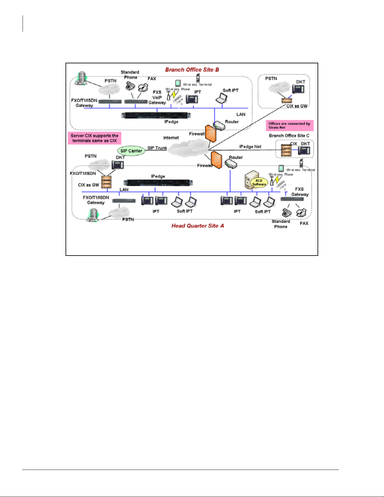
In a typical network configuration with IPedge, the IPedge server is placed behind the NAT
firewall and given a private IP address.
IPedge provides SIP trunking for incoming and outgoing calls. On the LAN, IPedge works with
the SoftIPT and IP telephones. An FXO/T1/ISDN gateway is used to connect the all IP IPedge
solution to PSTN networks.
Overview
Configuration
Strata CIX system users can migrate to IPedge and minimize their investment by using their Strata
CIX system as a gateway for PSTN interfaces and DKT telephones. The Strata CIX is networked
to IPedge through IPedge Net.
IPedge General Description 01/12 7
Page 22
Overview
Figure 6 Multi Node Confi guration
Configuration
Multi-node IPedge and Strata CIX systems can be networked together using IPedge Net.
8 IPedge General Description 01/12
Page 23

Software Support and Upgrade Service
Software Support and Upgrade Service
Toshiba’s Software Support and Upgrade Service (SUS) plan for IPedge provides a great way to
protect the investment in an IPedge system. It provides three important benefits: software updates,
technical support, and license transfers.
Software Updates – While covered under this plan, software updates for enhancements, new
features, and corrections may be applied to the IPedge system. Some new features may require
additional licenses. Software updates are obtained through the Authorized Toshiba Dealer. If the
SUS plan lapses, software updates may not be applied unless you pay additional charges to regain
current status for maintenance.
T echnical Support – Systems covered under the SUS plan are eligible for full technical support by
the Authorized Toshiba Dealer. If the plan lapses, technical support is billed “per incident” and
software updates are not available until the SUS plan is reinstated.
License Transfers – Systems covered under the SUS plan are eligible for license transfer when
upgrading to larger systems. A small transfer fee and equivalent license price differences may
apply. Licences are not eligible for transfer without a current SUS plan.
The first year of SUS is included with the purchase of a new IPedge system. At the time of
purchase, the SUS plan term may be extended for up to 5 years with a disc ount for purchasing
multiple years. Before the plan expires, the plan term again may be extended for 1 to 5 years, with
multi-year discounts available. An IPedge system with a lapsed Software Support and Upgrade
Service plan may reinstate the SUS plan for a fee of 125% of the annual rate over the lapsed
period. The term begins after purchase, when licenses are generated for the IPedge system.
Overview
This Software Support and Upgrade Service plan is available to the original owner of the system
and is not transferable. Registration and proof of purchase of the original owner of the IPedge
system may be required.
While Toshiba has made every effort at the time of publication to ensure the accuracy of the
information provided herein, this information is subject to change without notice. Toshiba assumes
no liability for any damages incurred directly or indirectly from any errors or omissions contained
herein. In no event will Toshiba be liable for any incidental, consequential, special or exemplary
damages, whether based on tort, contract or otherwise, arising out of or in connection with this
information or any other information contained herein or the use thereof. The terms and conditions
of Toshiba’s Software Support and Upgrade Service plan apply to the SUS plan. Visit http://
telecom.toshiba.com/Telephone_Systems_Support/warranty.cfm for details.
IPedge General Description 01/12 9
Page 24

This page is intentionally left blank.
Page 25

Telephones and Peripherals 2
This chapter covers Toshiba’s 5000-series Internet Protocol (IP) Telephones and peripherals that
are compatible with IPedge telephone systems.
IP 5000-Series IP Telephones
The IPedge system supports the IP5000-series telephone product line.
Toshiba offers many IP Telephone models with backlight displays (except IP5022-SD), full-
duplex speakerphones, and Gigabit Ethernet:
• IP5122-SD & IP5622-SD – 10-button IP speakerphone with 4-line x 24-character backlit
LCD. The IP5622-SD does not support Gigabit Ethernet, ADM, DSS, BESCB and carbon
handset/headset.
• IP5022-SD & IP5522-SD – 10-button IP speakerphone with 4-line x 24-character LCD
(without backlight)
The IP5022-SD & IP5522-SD have all the same characteristics as our IP5122-SD except the
backlight for the display. These telephones still have full feature functionality with its 4-line
display and 10 programmable buttons. However, the IP5022-SD supports Gigabit Ethernet,
while the IP5522-SD does not support Gigabit Ethernet, ADM, DSS, BESCB and carbon
handset/headset.
• IP5122-SDC – Looks and functions similar to the IP5122-SD telephon e when connected to the
IPedge system. This telephones fully support all the IPedge features and services of a regular
IP5122-SD telephone. However, this telephone can have a unique feature button called the
Analog Central Office (ACO) button to connect directly to your local Central Office. This
ACO feature enables you to make Emergency 911 calls and/or calls on your direct CO line by
bypassing your IPedge system. Power over Ethernet (POE) or AC power is required for the
telephone’s analog local line connection to operate.
• IP5132-SD – 20-button IP speakerphone with 4-line x 24-character backlit LCD
• IP5131-SDL, IP5531-SDL & IP5631-SDL– 20-button IP speakerphone with 9-line x 24character backlit LCD and HTML interface with navigation key. This telephone has 18 Soft
Keys located on the sides of the large LCD to respond to system feature prompts, ten of these
are programmable feature buttons. The Shift key (Purple key) toggles the LCD screen between
flexible keys 1~10 and flexible keys 11~20. The IP5531-SDL and IP5631-SDL do not support
Gigabit Ethernet and carbon handset/headset.
IPedge General Description 01/12 11
Page 26

Telephones and Peripherals
IP 5000-Series IP Telephones
IP5022-SD & IP5522-SD
10 programmable buttons, 4-line LCD
IP5122-SD, IP5122-SDC & IP5622-SD
10 programmable buttons, 4-line backlit LCD
IP5131-SDL, IP5531-SDL & IP5631-SDL
20 programmable buttons, large backlit LCD
with HTML support and navigation key
IP5132-SD
20 programmable buttons, 4-line backlit
LCD
12 IPedge General Description 01/12
Page 27

Telephones and Peripherals
IP 5000-Series IP Telephones
Features
The IP5000-series telephones include a speakerphone and are 802.3af standard compliant for
Power-Over-Ethernet (PoE). The IP Telephony product family also includes matching Add-on
Module and a DSS Console.
The IP5000-series telephones support a very comprehensive and powerful feature set including:
• Backlit Displays (except IP5022-SD)
• Gigabit Ethernet Switch (except IP5522-SD, IP5531-SDL, IP5622-SD and IP5631-SDL
telephones)
• Analog Central Office (ACO) button (IP5122-SDC only)
• Busy Lamp Field (BLF) display of station status.
• Background Music through telephone speakers.
• Paging over telephone speakers.
• IPT Anywhere
• Automatic Configuration
• Terminal Authentication (security)
• Off-hook Call Announce (OCA) over telephone speaker while the user is talking using the
handset.
• Built-in headset interface for headsets and external speaker connection (BESCB)
• IP Add-on Modules (except IP5522-SD and 5622-SD)
In addition, the 5000-series IP telephones contain several important features, including:
• Full-duplex speakerphone capability.
• 802.3af power over Ethernet compliant
• Soft Keys to respond to the IPedge feature prompts.
• Additional feature adjustments, such as setting button beeps, room noise sensitivity and
handset busy override tone.
• An adjustable tilt stand base is built-in, providing flexible angle adjustment of the entire
telephone.
Connectivity
The IP telephones connect to the IPedge system via the LAN or WAN.
• These telephones do not use the System power supply, so there is no power restriction to limit
the number of IP telephones that can connect to an individual IPedge system. The IP
Telephones have built-in connectors. The back of the telephone has connector labels. The
telephones can be powered by a local power supply or by PoE (Power over Ethernet).
• The RJ45 LAN jack connects the telephone to the network via the LAN cable supplied with the
telephone or with an optional power brick that can be ordered per IP phone.. These telephones
operate on the network at 10/100Mbps and 1000Mbps (IP5000-series with the exception of the
IP5522-SD, IP5531-SDL, 5622-SD, 5631-SDL telephones) and can be connected to a fast
switch hub, router, LAN, WAN, etc.
• The RJ45 PC jack can connect the IP telephones to the user’s PC. The IP telephones can
operate like a switch, as opposed to a hub, so the telephone can be connected directly to the
LAN or Cable/DSL modem, and then a PC can be connected to the telephone PC jack to
connect to the LAN through the telephone.
• The built-in headset jack enables headsets to be connected to the telephone. No optional
headset interface is required.
IPedge General Description 01/12 13
Page 28

Telephones and Peripherals
IP 5000-Series IP Telephones
Capabilities
The Toshiba IP Te lephones also have the following capabilities:
• The IP telephones contain two types of codecs (coder/decoder): G.711 and G.729A. The codec
determines the IP telephone voice quality and network bandwidth requirements. The G.711
requires the most bandwidth and provides the best voice quality. The G.729A requires less
bandwidth, but it does not provide the best voice quality. The desired codec can be selected for
each IP telephone in IP station administration using Enterprise Manager.
• The external ringer interface connector is mounted inside the telephone base. This enables
connection of an BESCB external speaker device to provide a loud ringer for the IP telephone.
• All telephones in the system can be IP telephones up to the system’s maximum station capacity
(see Table 15 on page 105).
• Terminal Authentication is an option that allows a particular IP telephone to keep a reserved
directory number on a IPedge system. This prevents IP telephones from logging in with another
telephone’s directory number if the other telephone has been disconnected to be taken to
another location. This feature uses the unique Media Access Control (MAC) address that is
permanently coded into each telephone network interface circuit. The unique MAC address of
the telephone is assigned to a particular directory number in system programming.
• IP telephone firmware can be updated locally or remotely using Enterprise Manager. This
enables service personnel to update IP equipment with new features and enhancements as they
become available. Updates require a brief interruption of IP telephone operation (a few
minutes).
• IP telephones have a discovery retry timer to prevent network congestion when many IP
telephones request services simultaneously. If network congestion is detected, the telephone
will pause and then retry for service.
• IP telephones have loop back and ping capabilities for maintenance and fault finding purposes.
• IP telephones support Dynamic Host Configuration Protocol (DHCP) or static IP addressing.
14 IPedge General Description 01/12
Page 29

Telephones and Peripherals
IP 5000-Series IP Telephones
Liquid Crystal Display (LCD) Models
The IP5022-SD, IP5122-SD, IP5522-SD, IP5622-SD, IP5122-SDC and IP5132-SD models
display up to 24 characters times four lines of information and provide four Soft Keys.
The IP5131-SDL, IP5531-SDL, IP5631-SDL has 4 soft keys and a 9-line LCD. From the idle
screen you can access telephone directories and speed dial lists of names or departments, internal
or external to the telephone system. You can search by name or letter within a list.
The IP5131-SDL screen consists of Phone, Config, and Web-application screens. The screens
change easily by pressing the tab soft key.
• Phone screen – This screen is a 150 x 168 pixel LCD screen.
• Config screen – This screen can be used for Telephone configuration settings. Using this
screen, you can set the IP address, subnet mask, etc.
• Web screen – provides users with the access to the web page. This capability can be used to
create the custom applications designed to match with IP5131-SDL phone screen so that the
user can enter or retrieve the data from the IP5131-SDL phone.
All LCD telephone models can provide:
• Advisory Messages
• Automatic Number Identification (ANI)
• Caller ID, Name and Number with call history
• Contrast adjustment (13 levels)
• Backlight adjustment, except IP5022-SD (On/Off/Synchronized)
• Date/Time of Day
• Dialed Number Identification Service (DNIS Name and Number)
• Feature Prompting Soft Keys that are used as an alternative to access codes or feature buttons.
Station users can access features by responding to LCD prompts.
• Called Number displays on outgoing calls (1~120 secs.)
IPedge General Description 01/12 15
Page 30

Telephones and Peripherals
IP4100 DECT Telephone and Base
IP4100 DECT Telephone
IP4100 DECT Telephone
The IP4100 DECT telephone (shown right)
supports 8~10 simultaneous call sessions per
base and allows for seamless roaming between
bases in a multi-base configuration. The High
Defination voice enabled speaker and
microphone allows for crystal clear speech.
The handsets support more than 20 hours talk
time and 200 hours standby time in normal
operations. The IP4100 DECT telephones are
administered via a powerful web-based
management tool that simplifies
administration and installation
Handset Features
• 2.0 inch color TFT back-lit display
• Li-ion battery for long talk time and
standby time
• Wideband Voice (HDSP) Basic and
Extended operations
.
• Over-air feature upgrade support
• DECT 6.0 frequency support with encryption
• Back-lit keypad for easy operation in low-lit environments
• Laser-etched keypad numbers for extended life use
• Three soft keys for ease of operation
• Four programmable feature keys for flexibility in operations
• 2.5 mm headset jack
• Polyphonic ringer support
• Vibration ring support
• Additional battery charging station in handset charger
• High-quality speaker phone
• Belt clip
IP4100-BASE Features
• Attractive design
• Power over Ethernet support
• Omni-directional internal antenna for flexible installation options
• Antenna diversity switching to avoid interference
• Frequency support 1920-1930mhz with Wi-Fi avoidance technology
• Colored LED status indication for ease of installation and operation
• Easy installation via web GUI interface
• Built-in trouble-shooting tools.
16 IPedge General Description 01/12
Page 31
Telephone Button Expansion Options
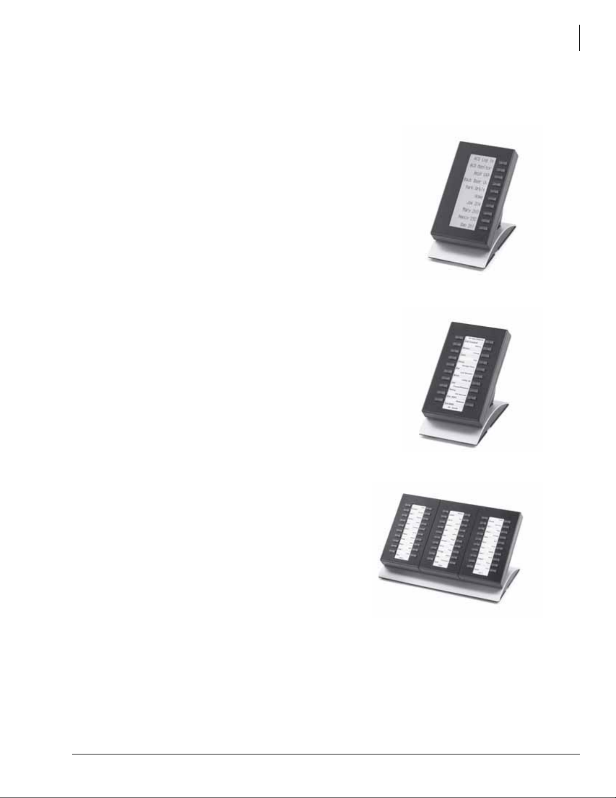
Upgrade options for the Toshiba IP telephones are described below.
LCD Add-on Module (LM5110)
The LM5110 adds 10 programmable LCD feature buttons to
the 5000-series telephones (except the IP5522-SD and IP5622SD telephones), these buttons can be assigned as CO line,
Directory Number, DSS, One Touch, Speed Dial or any other
flexible feature.
The LM5110 supports backlight and LCD labels, it can be
connected to any IP5000-series telephone.
Key Module (KM5020)
Telephones and Peripherals
Telephone Button Expansion Options
The KM5020 adds 20 programmable feature buttons to the
5000-series telephones. These buttons can be assigned as CO
line, Directory Number, DSS, One Touch, Speed Dial or any
other flexible feature.
IP Direct Station Selection (IDM5060) Console
The IDM5060 console (shown right) is for system
attendants.
The IDM5060 operates alongside an IP telephone and has
60 programmable feature buttons. These buttons can be
assigned as CO Line, Directory Number, DSS, One
Touch, Speed Dial or any other flexible feature.
Up to three consoles can operate with one IP telephone.
However, the IP5522-SD and IP5622-SD telephones do
not support an IDM.
The IDM5060 console uses LEDs to indicate call and feature status; the DSS has dual red and
green LEDs to help further define status, such as station in DND status. The IDM5060 console
connects directly to an IP5000-series station.
IPedge General Description 01/12 17
Page 32

Telephones and Peripherals
Attendant Console
Attendant Console
The Attendant Console runs on a PC with Microsoft® Windows XP Professional or Windows 7
(32 bit) operating system. The Attendant Console PC offered by Toshiba is equipped with an Intel
two gigahertz CPU in a small, compact desktop chassis that is just the right size for a receptionist’s
desk. If there isn’t any room on the desk for the system to lay flat, it can also be stood on its side
for an even smaller footprint. Add to that the powerful IPedge Attendant Console software, and
you have a winning solution for any IPedge installation!
The Console has a built-in softphone for IPedge and uses a Computer Supported Telephony
Application (CSTA) interface.
Each Attendant console requires the I-CP-AUX, the basic port license, and the I-CP-ATT license
which is bundled with the Toshiba supplied Attendant Console PCs and software. The I-CP-ATT
license must be ordered separately to enable the Console to be installed on a Dealer / Customer
supplied PC. The latest Attendant Console software is available at no charge on Toshiba FYI.
The minimum PC requirements for the IPedge Attendant Console are:
• Operating Software – Microsoft Windows XP Professional or Windows 7 (32 bit)
• Processor – 2.0GHz Intel Pentium 4, Celeron or higher
• Memory – 1GB RAM
• CD-ROM Drive, CD-R/W Drive or DVD capable of reading CD-ROM data files to install
Attendant Console software.
• Hard Drive: 500M space available
• Sound card with internal or external speakers
• I-CP-ATT must be ordered separately if using a Dealer supplied PC for the Attendant Console
Toshiba offers IPATTCONS, a complete attendant console system with the following items:
• Attendant Console License (I-CP-ATT) for the IPedge system
• Intel Pentium D Dual Core 1.8GHz CPU
• 1GB Random Access Memory (RAM)
• DVD R/W drive
• Windows XP Professional (factory installed)
•IPedge Attendant Console software (factory installed)
• Comprehensive set of multimedia inputs and outputs
• Keyboard & Mouse
• PC Headset (Jabra 2000)
• Attendant Keyboard stickers (Black) CIX-BL-ATCON-VA
Optional item:
• 17” Flat screen Monitor – Toshiba offers a 17” Liquid Crystal Display (LCD) flat screen
monitor; part number CTX-LCD-MONITOR.
18 IPedge General Description 01/12
Page 33
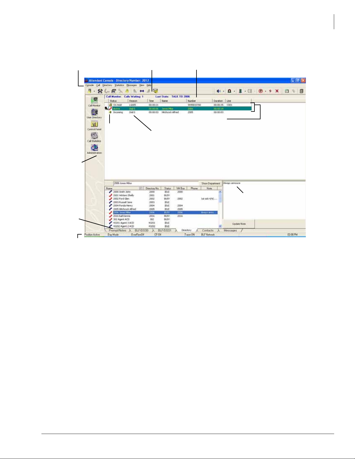
Telephones and Peripherals
Menu Bar
Info Bar
Toolbar Icons
Call List
Call Status
icons
Call Attributes
View P ane
Icons
Notes
Call
Monitor
Tabs
Directory
Status Bar
Attendant Console
The Attendant Console is designed to handle all call activity within a single Call Monitor screen,
shown below. All calls will appear in a single list.
Calls are marked with icons to show the current status.
Features such as Paging, Call Pickup, Call Park offer many alternatives. The Administration
window enables which option is the primary operation for that Attendant. For example, if two
zones are used for paging, as well as the All Call, then an option pull down arrow is next to the
icon. Clicking the icon starts the All Call Page, then the Attendant can select one of two page
zones.
All other views available for the Attendant are for administrative and management use. They do
not control any type of call handling except how chosen options affect the overall operation.
The Attendant Console also enables an attendant to manage console settings, maintain a user
directory, and view call statistics. The Console provides a Name/Number search that works with
automatic or manual call handling. Other features include Queuing, DSS, signaling, Emergency
Call ID, keyboard or mouse operation, and headset or handset operation with volume control.
IPedge General Description 01/12 19
Page 34
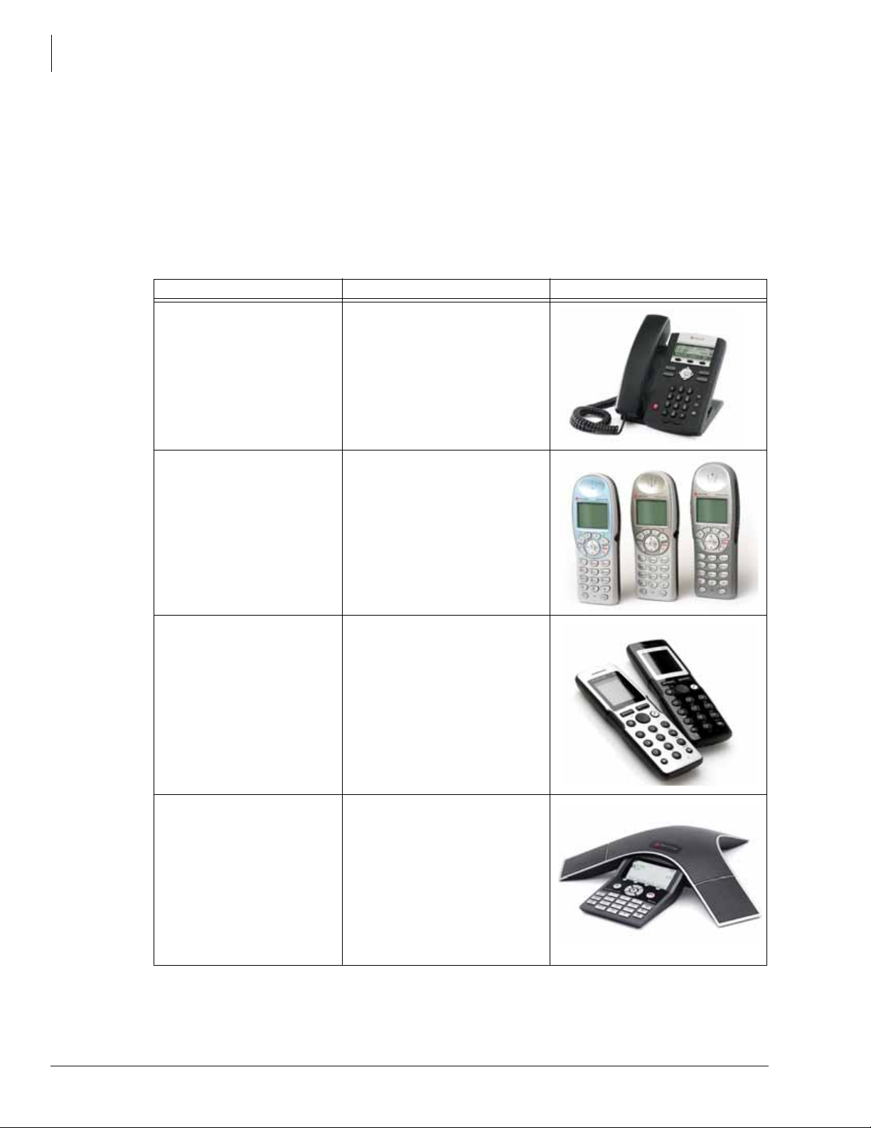
Telephones and Peripherals
Peripherals
Peripherals
The IPedge supports a variety of third party peripherals in order to meet specific business needs.
Polycom End Points
The IPedge call control platform supports a variety of end points from Polycom. The following
table lists end points (by type – desk phones, wireless, conference etc) that have been qualified to
work with IPedge.
Table 2 Polycom End Points
Type IPedge - End Points Supported Image
Desk Phones
SoundPoint IP 321
SoundPoint IP 331
SoundPoint IP 450
SoundPoint IP 550
SoundPoint IP 560
SoundPoint IP 650
SoundPoint IP 670
WiFi Wireless Phones
KIRK DECT Wireless Phones
Conference Phones
SpectraLink 6020 (connects via a
gateway)
SpectraLink 8002
SpectraLink 8020
SpectraLink 8030
SpectraLink e340, h340, i640
KIRK 2010
KIRK 4020
KIRK 4040
KIRK 5020
KIRK 5040
Note: These digital telephones
use Polycom gateways that
connect to the IPedge system.
SoundStation IP 7000
SoundStation IP 6000
Note The list of supported end points changes as Polycom brings new products to market. For the
most recent versions supported Polycom end points, Data sheets, etc, refer to Internet FYI >
TSD 3rd Party Partners > Polycom page.
20 IPedge General Description 01/12
Page 35
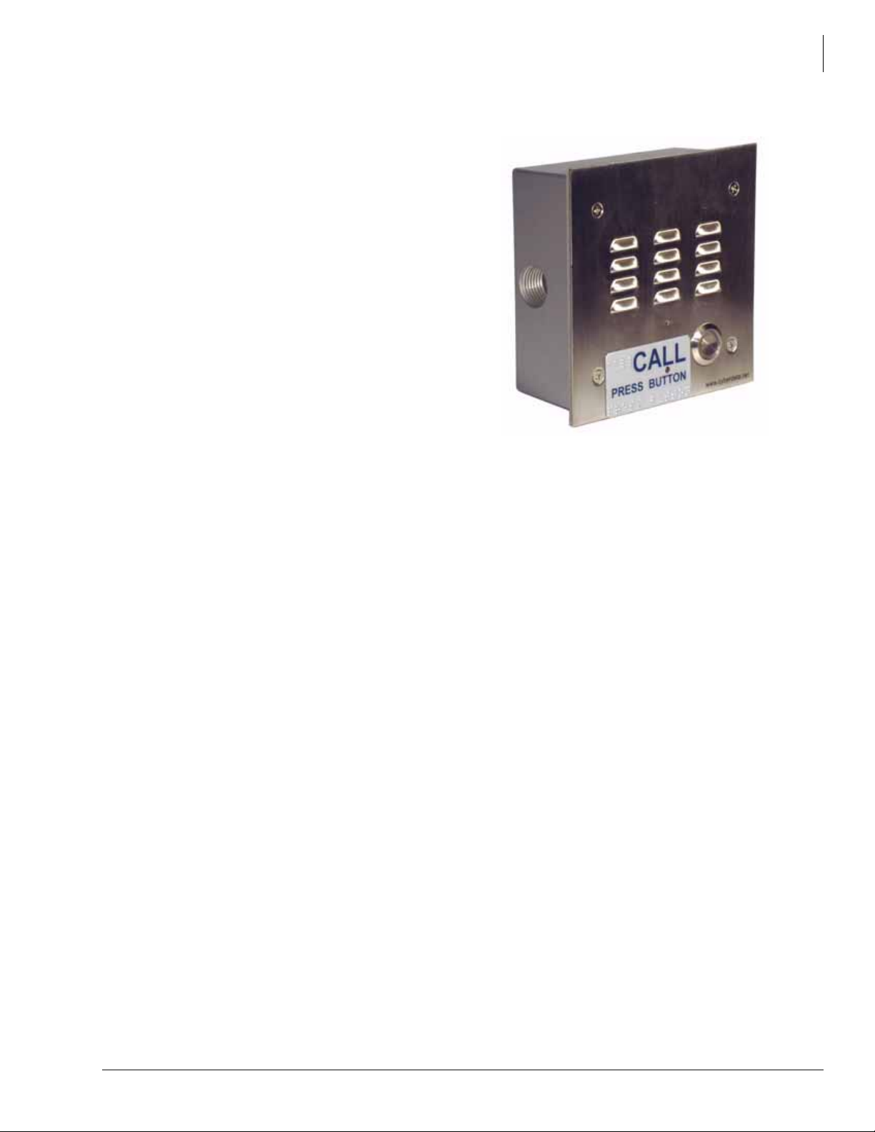
CyberData
The CyberData® Voice-over-IP (VoIP) Intercom product
is targeted for door phone, emergency phone, and
access control applications.
The CyberData VoIP Intercom product operates over a
Local Area Network (LAN) and is Power-over-Ethernet
(PoE) 802.3af enabled. SIP line extension dialing and
features allow the user to use the IPedge capabilities for
two-way communications or as a paging speaker as
required.
The VoIP Intercom provides adaptive full-duplex voice
operation, along with network adjustable speaker volume
and microphone sensitivity. The product is easily
configurable via a network web management utility.
Providing door closure and tamper alert signaling, the
VoIP Intercom has a tamper-resistant design that allows
the unit to be mounted securely and safely. Network
downloadable firmware support allows for easy upgradeability.
Telephones and Peripherals
Peripherals
The CyberData VoIP Intercom provides:
• SIP RFC 3261 compliance
• LAN Ethernet 10/100 Mbps
• G.711 (A-law and µ-law) codec support
• Single press call button
• Call activity indicator (light)
• POE 802.3af compliance
• One dry contact relay for auxiliary control
• Tamper-resistant design
• Network web management
IPedge General Description 01/12 21
Page 36
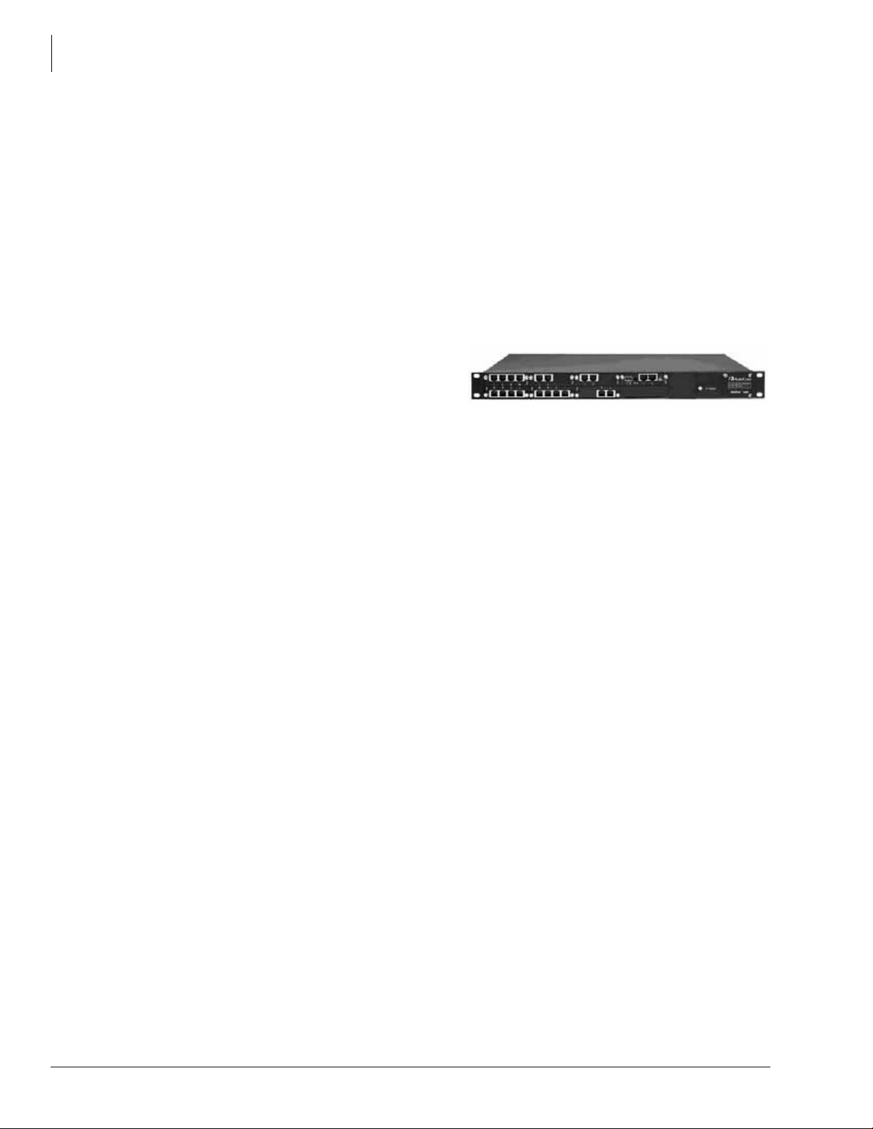
Telephones and Peripherals
Peripherals
Gateways
A VoIP gateway is hardware equipment that converts Time Division Multiplexing (TDM)
telephony traffic from the Publicly Switched Telephone Network (PSTN) into digital IP packets
for transport over an IP network. A VoIP gateway can also convert digital IP packets into TDM
telephony traffic for transport across the PSTN. VoIP gateways have become a central, yet
complex, component in most state-of-the-art VoIP systems. Other functions of a VoIP ga teway
include voice compression or decompression, control signaling, call routing, and packetization.
VoIP gateways come in many different configurations. Toshiba sells some third party gateways.
Audiocodes
Mediant 1000 Series (Digital)
The Mediant 1000 (shown right) is
Audiocodes’cost-effective, converged wireline
VoIP media gateway. Intelligently packaged in a
stackable 1U chassis, it is designed to interface
between TDM & IP networks in enterprises or
small-scale carrier locations. Incorporating
AudioCodes’ innovative Voice over Packet technology, the Mediant 1000 enables rapid time-tomarket and reliable cost-effective deployment of next-generation networks.
The Mediant 1000 is based on VoIPerfect, AudioCodes' underlying, best-of-breed, media gateway
core technology for all of its products. The Mediant 1000 provides superior voice-technology for
connecting legacy telephone and PBX systems to IP networks, as well as seamless connection of
the IP-PBX to the PSTN. The Mediant 1000 is fully interoperable with multiple vendor gateways,
Softswitches, gatekeepers, proxy servers, IP phones, Session Border Controllers and firewalls.
The Mediant 1000 matches the density requirements for small locations while meeting enterprises’
and service providers’demands for scalability. The compact Mediant 1000 Modular Gateway is
extremely scalable and supports multiples of 1, 2, or 4 E1/T1/J1 spans, 4 to 20 BRI ports or 1 to 24
analog ports in various FXO/FXS configurations. The Mediant 1000 also supports mixed digital/
analog with media processing capabilities such as conferencing, play/record configurations.
The Mediant 1000 can support a variety of telephony interfaces. The digital module can be
configured as regular E1/T1/J1 interfaces, with up to 1 or 2 paired spans acting as life-line
interfaces for switching to the PSTN in case of power failure or network problems. The analog
module is available as regular FXS or FXO interfaces, where 1 FXS line can be used as a life-line
interface for switching to the PSTN.
Interface Modules:
• Digital (E1/T1/J1) – connecting the PSTN or PBX to the IP-network
• Analog FXS – connecting analog phones to the IP-network
• Analog FXO – connecting analog trunks to a CO line
For Mediant 1000 series parts, refer to Audiocodes Parts, Table 26 on page 114.
22 IPedge General Description 01/12
Page 37

Telephones and Peripherals
Mediapack Series (Analog)
TM
The MediaPack
Series Analog VoIP Gateways are cost-effective, best-of-breed technology
products. These stand-alone analog VoIP Gateways provide superior voice technology for
connecting legacy telephones, and PBX systems with IP-based telephony networks, as well as for
integration with new IP-based PBX systems.
MediaPacks are well suited for commercial VoIP deployment because of their mature and fieldproven voice technology. Their rich feature set allows integration with a wide range of Carriers
and Enterprise network applications. MediaPack gateways are used by Carriers and Service
Providers in Access networks for connecting Multi-Tenant Units (MTU), IP Centrex subscribers,
pay phones and rural users over various wireless and satellite links.
Enterprises use MediaPack gateways to connect their legacy PBX systems over an IP
infrastructure. In addition, in IP Centrex and central IP-PBX applications, the MediaPack
increases the remote location availability and provides Stand Alone Survivability (SAS) when
there is no IP connection between branch locations and the central SIP servers, SIP Proxy or
central IP-PBX.
MediaPacks are third generation products that have been designed to meet real market needs. In
addition to superior voice technology, the products provide advanced telephony features such as
long-haul, metering tones generation, country dependent MWI and CID for true integration with
the existing telephony infrastructure. A variety of management and provisioning tools, such as
AudioCodes’ EMS, embedded web server, Telnet and SNMP enable fast deployment and
management of large and complex networks. MediaPacks are based on VolPerfect
TM
architecture,
AudioCodes underlying, best-of-breed, core media gateway technology for all of its products.
Peripherals
MediaPacks are part of AudioCodes’complete family of stand-alone VoIP Gateways for OEM
system integration. Support of multiple VoIP control protocols has been tested with leading
Softswitch vendors. As a provider for OEMs, System Integrators and Network Equipment
Providers, AudioCodes offers short time-to-market with field-proven products.
MediaPack Series Features
• Spans a range of 2 to 24 analog ports
• Supports PSTN/PBX analog telephone sets or analog trunk lines (FXS/FXO)
• Selectable, multiple LBR coders per channel
• T.38 compliant – Rich subscriber Feature Set including; 3-Way conference with local mixing,
call pickup, hunt groups, call forwarding, call hold, call transfer
• Echo cancelation, Jitter Buffer, VAD and CNG
• Enhanced capabilities which include MWI, long-haul, Metering Tones, STUN, Security
features, Generation, CID and outdoor protection
• Stand Alone Survivability (SAS) for SIP based IP Centrex and Central IP-PBX applications
• Web Management for easy configuration and installation
• EMS for comprehensive management operations (FCAPS)
• Automatic provisioning via TFTP/HTTP – Internal Access List firewall for network traffic
filtering
For Mediapack series part numbers, refer to Audiocodes Parts, Table 26 on page 114 .
IPedge General Description 01/12 23
Page 38

Telephones and Peripherals
Peripherals
Epygi Gateways
The Epygi Gateways (shown right) are
available in a sturdy metal rackmountable housing that permits the
inclusion of a built-in power source and
cooling fan for heavy duty operation and
extended life span.
These gateways include call routing and auto attendant capabilities, voice prioritization over data
and sophisticated firewall and security elements. The QuadroM functions primarily to bridge
traditional PBX traffic to the Internet, reducing costs and simplifying system administration.
QuadroM E1/T1 Single-RM Gateway – This model features 30 channels of compressed g.729
codec and conforms to a broad variety of voice codecs and signaling protocols. Architecture and
design enhancements improve sound quality and application integration.
QuadroM Dual E1/T1 – This model doubles the call capacity of the QuadroM E1/T1, affording
as many as 60 simultaneous calls (48 simultaneous calls for T1– US and Japan) from the two
broadband trunks.
The QuadroM Dual E1/T1 30 features 30 channels of g.729 compression codec.
The QuadroM Dual E1/T1 60 allows for 60 channels.
Sound quality and application integration match the quality of the QuadroM E1/T1 with single
port.
Table 3 Epygi Gateway Comparison Table
E1/T1 Single-RM E1/T1 Dual 30-RM E1/T1 Dual 60-RM
Part Number SKU-QM-0002 SKU-QM-0003 SKU-QM-0004
Ports for analog
telephones or devices
Single/Dual E1/T1 ports
E1 / T1 Ports 1 2 2
Ethernet LAN Ports 1 1 1
Ethernet WAN Ports 1 1 1
111
Single: 30 simultaneous
calls (E1); 24 (T1)
Dual: 48 simultaneous
calls (E1), 48 (T1)
60 simultaneous
Dual:
calls (E1), 48 (T1)
24 IPedge General Description 01/12
Page 39
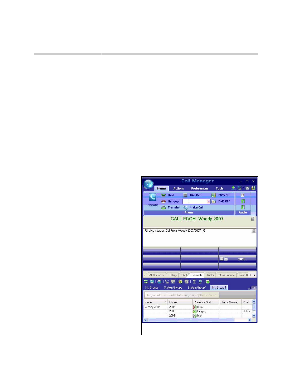
Unified Communications 3
Call Manager Presence Screen
This chapter describes IPedge Messaging, Call Manager, Meeting, and Mobility Solutions which
together form Toshiba’s Unified Co mmunications product suite. The IPedge system supports all
Unified Communications (UC) applications on one platform, dramatically decreasing the cost and
complexity of deploying multiple applications. This includes Presence, IM/Chat, PC call control,
Auto Attendant, Voice Mail, Unified Messaging, Interactive V oice Response (IVR), and Enterprise
Manager system administration.
The Unified Communications product suite is easy to acquire, deploy, manage, and use. You can
select the mix of modular capabilities that meet the specific needs of your business. Some of the
key features and benefits of these tools are mentioned below:
• Presence and Instant Messaging –
With a presence viewer you can see
the status of other users, both their
telephone busy/idle status and
calendar status from Outlook
integration, with the ability to click
on the name to either call or instant
message chat with them. You can
decide the best way to contact
someone to maximize efficiency.
• Outbound Dialing from Any
Application – Making a call is as
easy as highlighting a number and
clicking the mouse. You can also
launch electronic documents,
applications and web pages directly
from the SCM interface for quick
access to the most frequently used
communications tools. This saves you
valuable time.
• Desktop Call Control – Using the
Toshiba Call Manager (CM) desktop
call manager application, you can
combine the capabilities of your
computer and telephone to dial,
answer, or transfer calls, and more,
using your mouse without ever
picking up the telephone. Clicking on
features make call transfer, speed dialing, and other functions faster and easier. SCM can be
IPedge General Description 01/12 25
Page 40
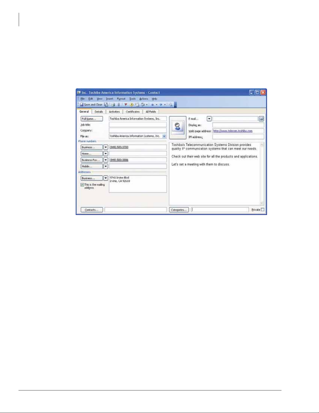
Unified Communications
used at your desk with your desk telephone or as a stand-alone IP soft phone providing mobility
and remote access. You get the efficiency of combining your telephone and computer into one
integrated communication tool.
• CRM Integration and Screen-pops – Your call answering personnel can provide better
service by immediately knowing which customer is calling with screen-pop integration to your
customer relationship management applications and databases. This saves you time and serves
your customers better.
• Off-premise Call Forwarding – Enables your incoming calls to reach you when you’re out of
the office and enables you to change your forwarding destination from any remote location.
You can stay in touch no matter where you are.
26 IPedge General Description 01/12
Page 41
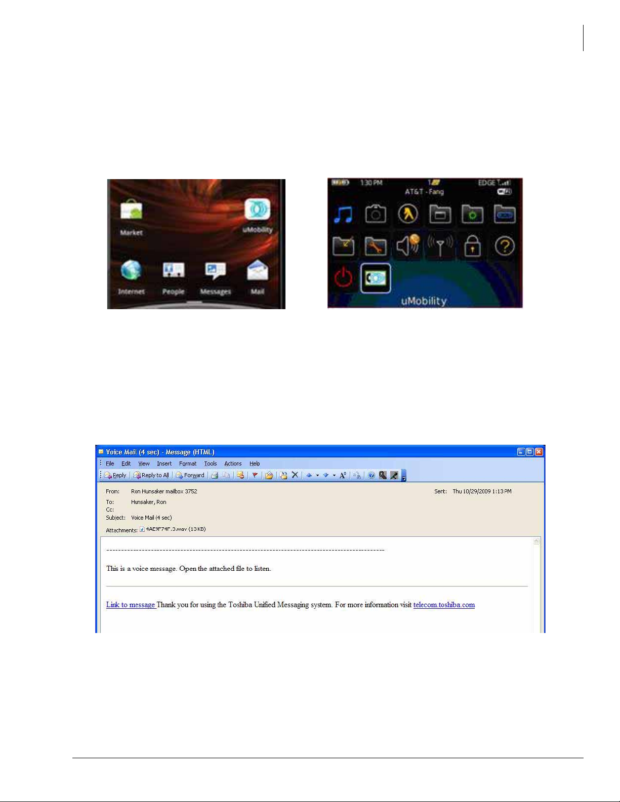
Unified Communications
Android BlackBerry
• Fixed Mobile Convergence – Toshiba’s uMobility solution empowers mobile workers to
make and answer their IPedge system calls from virtually anywhere. The user’s smart cell
phone functions as their IPedge system extension phone both while in the office via the
wireless LAN and while out of the of fice via a cellular net work. This is the most advanced level
of mobility and insures the most expeditious handling of your incoming calls.
• Unified Messaging – You can access your voice messages from your email inbox, providing
the convenience of checking all your messages from one place. Web-based unified messaging
adds mobility allowing users access to their email, voice by using only an Internet browser,
without even needing to first access their email providers. This is especially useful when away
from the office; enabling mobile users to access and manage their voice from anywhere they
have internet access.
• Remote Connection and Mobility – You may have a mix of on-site employees,
telecommuters who work at home, mobile employees, and personnel in remote branch offices.
It’s important to improve employee productivity for all of them no matter where they are.
Toshiba provides the tools for remote connectivity and mobility to make them all operate as if
they were right there in the office.
IPedge General Description 01/12 27
Page 42

Unified Communications
IPedge Messaging
IPedge Messaging
Messaging is an integrated voice processing application within the IPedge system that provides
standard voice mail and Automated Attendant features as well as Unified Messaging capabilities,
Follow Me, Message Notifications, Soft Key navigation of mailbox menus, and Call Recording.
Since Messaging is incorporated into the IPedge system, it delivers streamlined user
administration and system management. With it, users can easily and conveniently manage their
voice messages with intuitive on screen prompts. Users can program different types of greetings,
call routing, and message notifications.
Some key features include:
Follow-Me
A mailbox can be set up to forward a call to an external phone number before the call is transferred
to voicemail. When using supervised follow-me, the mailbox owner can perform functions such as
record the call, conference in another subscriber, or send the caller back to the mailbox owner’s
voicemail box.
Follow-Me Connect Verification
The mailbox owner can positively accept the follow-me calls by pressing a key to prevent calls
from ending up in cell phone voicemail or other telephone answering devices.
Follow-Me Record to Mailbox
Allows the mailbox owner to record a conversation that has been answered at the follow-me
number. The conversation is saved and sent to the mailbox owner’s voicemail box as a new
message.
Follow-Me Transfer Back
After the mailbox owner receives the call to the external device he can redirect the caller to another
internal extension.
Unified Messaging
Unified messaging allows a mailbox owner to access voice messages directly through an email
inbox. Emails may also be listened to from the voicemail box.
Integration with Email Clients
IPedge Messaging unified messaging provides seamless and fully synchronized integration with
existing email clients without the requirement of a desktop client. This allows Messaging unified
messaging to be desktop operating system-independent and greatly minimizes administration and
deployment workload.
Messaging as an IMAP Server
This is an independent mail server configuration where voice and deleted messages appear in a
separate folder from the mailbox owner’s primary inbox. Messages are synchronized with IPedge
Messaging.
Messaging as a POP Server
This is an independent mail server configuration where voice messages are displayed in the
mailbox owner’s primary inbox. Messages are not synchronized.
Other Messaging Features
Refer to “Messaging” on page 81.
28 IPedge General Description 01/12
Page 43
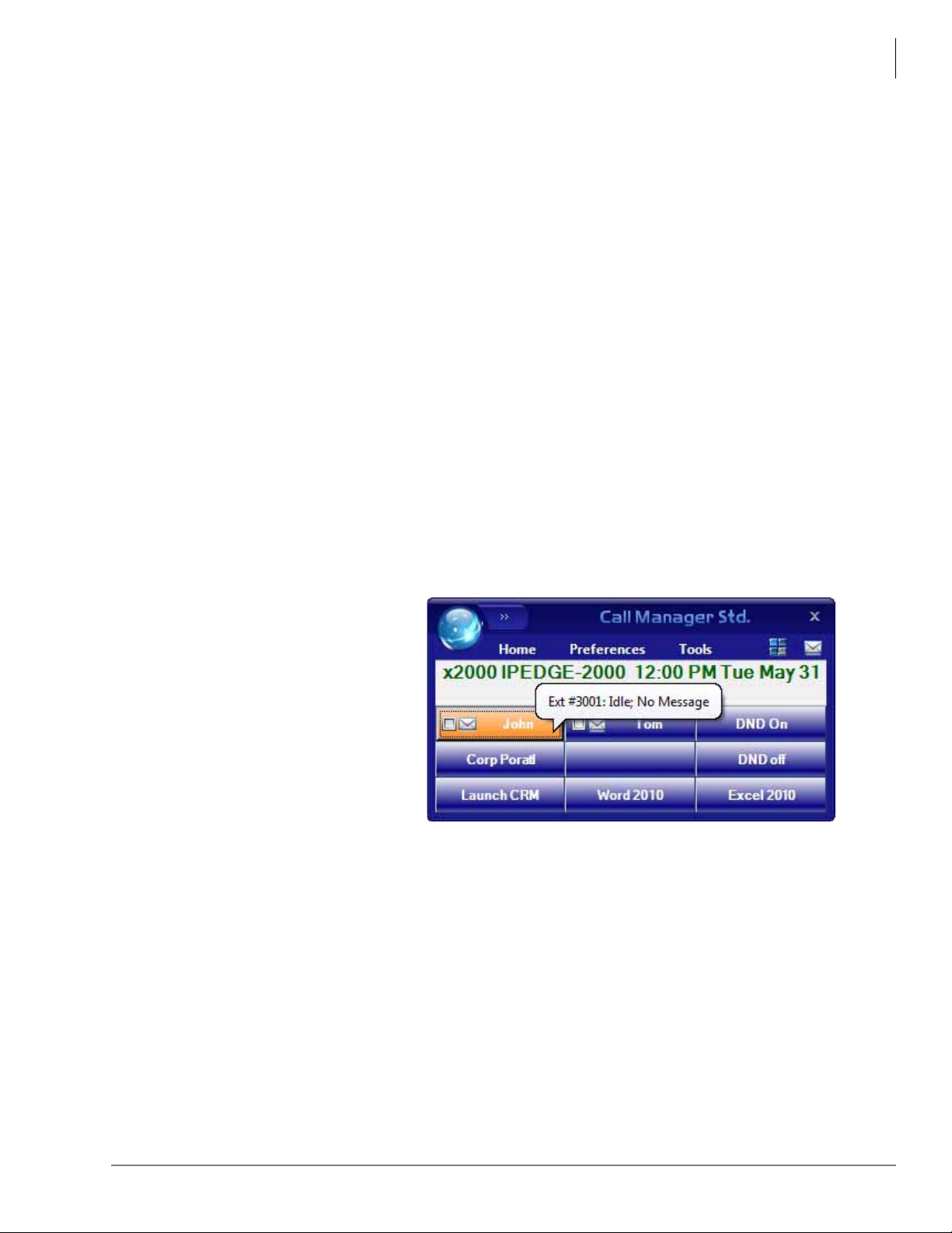
Call Manager
Call Manager (CM) is a powerful unified communications tool, a PC soft phone designed to
enhance productivity for mobile and office users.
The Call Manager application runs on a PC with Microsoft® Windows XP, Windows Vista, the
Terminal server on Windows Server 2003 ~ Windows Server 2008 R2, or Windows 7 operating
systems.
There are two levels of IPedge Call Manager:
• Call Manager Standard version is free to all users of the IPedge system. The license (I-CM-
STD1) for Call Manager Standard is included in the user license bundle at no additional char ge.
• Call Manager Advanced version provides enhanced functionality, including full Unified
Communications (UC). Purchase Call Manager Advanced license (I-CM-1) when full UC
capabilities are required.
ACD customers and/or Network Call Manager customers must purchase the full featured Call
Manager Advanced as the Call Manager Standard is not supported under this environment.
Call Manager clients connect to the Net Server running on the IPedge system with the appropriate
license (I-CM-1/I-CM-V1) on IPedge. When Call Manager is used with ACD or Unifier, it must
connect to the external server with ACD or Unifier with the appropriate license (LICMASNETSEAT) for the server.
Unified Communications
Call Manager
Call Manager Standard
Call Manager Standard provides the following major functions:
• Call control support (dial,
answer, transfer, with drag and
drop operation)
• 9 configurable buttons for any of
the following features:
• DSS/BLF (status display)
• Feature access code
•Run Program
•Speed Dial
• System/PBX Command
•Web URL
•LCD View
• Dialing from Microsoft Outlook Contacts
IPedge General Description 01/12 29
Page 44
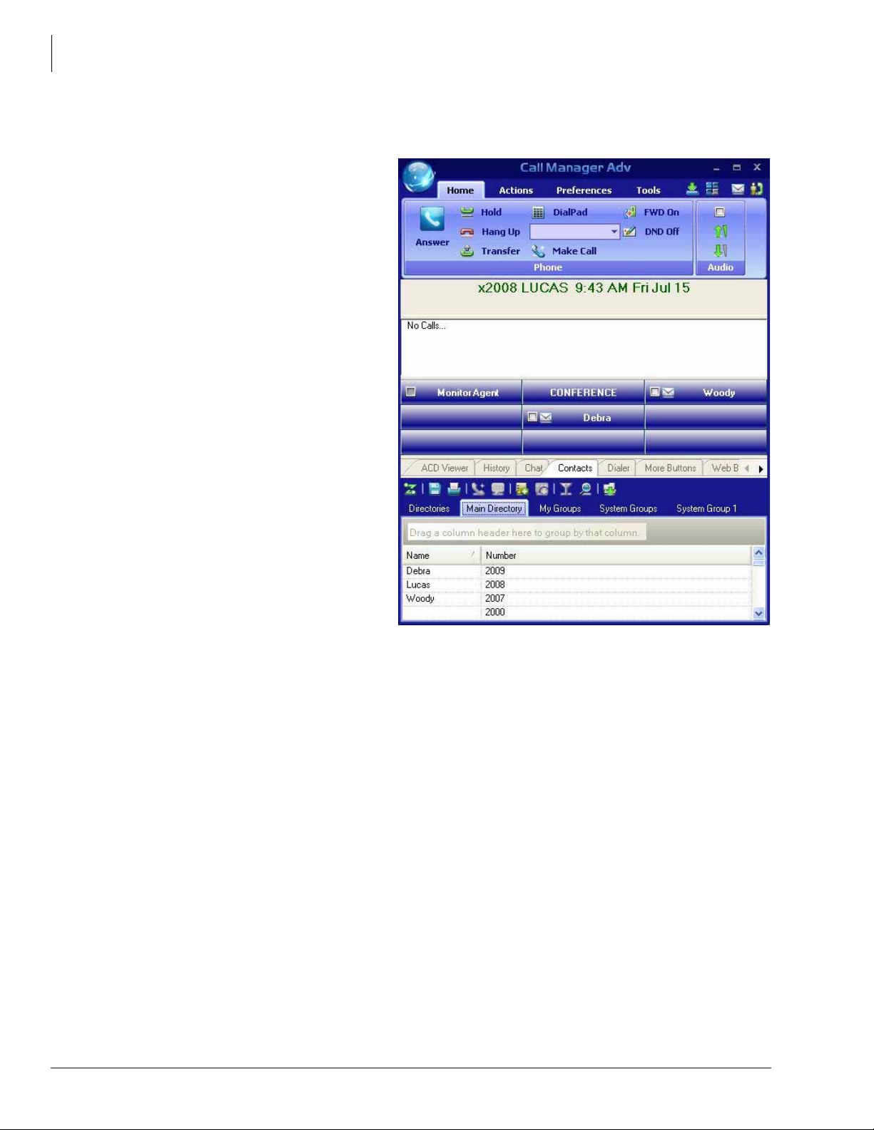
Unified Communications
Figure 7 Call Manager Main Page
Call Manager
Call Manager Advanced
Call Manager Advanced provides the following major functions:
• Desktop call control from your
PC
• Customized call handling – CM
allows you to place, answer,
handle, view, and manage phone
calls using your computer screen,
keyboard, and mouse.
• Outbound dialing from any
application
• CRM integration with screen pops
– CM can easily interface with
many popular programs (like
Microsoft Outlook, Salesforce
CRM, ACT , etc.). This allows you
to dial from and “screen-pop” into
these programs or the Internet /
Intranet.
• Presence Viewer to display the
status of other users
• Instant Messaging / Chat
• Using the VoIP Audio capabilities
can provide a complete soft phone
speech path when using a PC with
the proper speech component
support.
• Rules and actions can be set up to
automatically activate when calls
arrive even while you are away.
The Call Manager is based on the Microsoft Fluent User Interface which is easy to use and
manage.
Microsoft’s fluent user interface breaks the ribbon GUI down into multiple tabs. The tabs are
broken down into groups. The ribbon groups all the common features and functionality together.
Each tab has a specific function and all the buttons in that tab support that specific function. For
example, the Home tab encompasses all the basic telephony functions including: Hold, Transfer,
Hang up, and Make Call.
30 IPedge General Description 01/12
Page 45
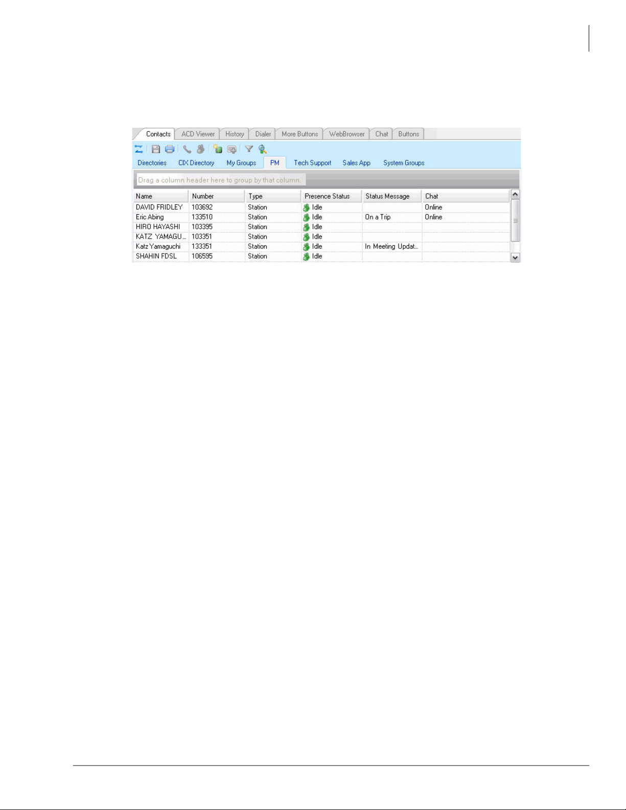
Unified Communications
Companion Applications
The Call Manager application supports some powerful companion applications. The Companion
application tabs are shown below.
Contacts (Directory, Presence Viewer and Speed Dial)
The Contacts companion application performs three features: Directory, Presence and Speed Dial.
The Contacts application provides a powerful set of directory features that allow you to look up
and dial IPedge system extensions with a click of the mouse.
Call Manager
The directory functionality in Contacts is generated by the system so it is always up to date with
every extension. The directory can be easily searched and sorted by name and number. In addition
to sorting by column name, the Contacts application now has a grouping feature where you can
drag a column name into the grouping section and the resulting list will be grouped by the column
name.
The Contacts application also has a Presence status column so you can quickly view the current
status of the user’s phone. Right-clicking on any user brings up a window that enables you to
either call, chat, send broadcast, edit or delete.
History
The History companion application automatically creates a log of calls dialed, received and missed
on the local telephone extension. The Call History can be searched for specific calls by date,
telephone number, name or account code. Calls can be automatically dialed by double clicking the
call in the Call History window.
The entire Call History or a search result can easily be printed or exported to a file. In addition to
sorting by column name, the History application also has the new grouping feature where you can
drag a column name into the grouping section and the resulting list will be grouped by the column
name.
ACD Viewer
The Call Manager is tightly integrated with the ACD from Toshiba. The Call Manager ACD
Viewer enables users connected to ACD to view the status of all ACD groups in which they
belong. This additional functionality does not require MIS software to be installed. Call Manager
shows the operating status of each group. Each group view can be expanded to see the number of
calls and the status of each of the agents and supervisors in the group. Each group contains a “My
Status” icon showing your own status in the group (logged in, logged out, busy, in wrap-up, etc),
and the status can be changed by right-clicking on the icon.
IPedge General Description 01/12 31
Page 46

Unified Communications
Call Manager
Chat
The Call Manager Chat application enables Call Manager users connected to the IPedge system to
interactively have chat conversations. Chat also supports whiteboard and canned messages. This
program enables employees in an enterprise to communicate using real time text-based
communications.
Using Call Manager Chat you can have individual conversations with anyone else on the server
with the same feature installed. Chat can also be used to send a broadcast message to an individual
or to an entire group. A broadcast message is a one-time message that will appear on the
recipient’s Chat window.
Dialer
Call Manager Dialer enables users to easily schedule phone calls to be placed later. For example,
when a sales representative arrives in the morning he may know he needs to make calls to 15 of his
customers, so from Microsoft® Outlook® he can drag and drop the contact information of all 15
of the customers into Dialer. When the designated time arrives for each call to be placed the user
will be presented with a pop-up screen alerting him that it is time to place the call. Once the call is
finished, the user will be presented with another pop-up screen requesting information about
whether the call was successful and if not whether it should call again later (for example if the
party was busy). The Personal Power Dialer displays all calls yet to be placed as well as calls that
have recently been completed, plus as the status of the dialers and the phone.
Web Browser
The Call Manager provides an integrated web browser window for access to Internet or Intranet
locations, or direct access to local HTML files. In addition to basic browsing, you can create
custom web applications to extend the functionality of Call manager for your business. For
example, your call center could have incoming calls automatically open the Call Manager browser
window to a “Caller Survey” page. The Call Survey page could display information about the
caller and display an answering script the agent could use to guide the conversation. The web page
might also allow the agent to enter answers from the caller into HTML forms and submit the
results to a company web server.
More Buttons
Call Manager has many different User Programmable buttons on the main screen and side window.
These buttons can be easily configured by the user as DSS buttons, Feature buttons, Speed Dial
buttons, User Action buttons, ACD buttons, etc. This provides the user with one-touch access to
features, applications, files, phone numbers, employees and more.
32 IPedge General Description 01/12
Page 47

Meeting
System Availability: IPedge EC and EM systems only
The Meeting application is integrated into the IPedge system. Meeting allows participants to dial
into a single conference or any combination of conferences. Meeting is web-based, so it’s easy to
set up conferences from anywhere, view conference participation during a call, and share a
desktop screen. There can be up to four conferences with a total of 24 audio and web participants
on the IPedge EC system and up to eight conferences with a tot al of 48 participants on IPedge EM
system. Below is a list of features available with the Meeting application.
Audio Conference Features
• Reservation-less and Scheduled Meet-me Conferencing – enables conferences to start
quickly and can be organized flexibly.
• Web User Interface for Moderators – enables moderators to schedule conferences.
• Conference View – shows moderators the participants that are in their conference and enables
the management of individual participants. Participants can be muted, disconnected, or
transferred to another conference for a side bar and conversation.
• Telephone Portal for Moderator and Participants – enables moderators and participants to
exercise in-conference controls via DTMF.
Unified Communications
Meeting
• Outlook Calendar Integration – allows meetings to be easily scheduled and invitations
distributed to all participants.
• Web-based Reporting – enables managers to have a view into the impact of audio conferences
and web collaboration sessions in their business.
• Moderator and Participants Codes – adds security and control to who can manage and
participate in conferences.
• Exit and Entry Tone – lets participants know when people are entering and leaving
conferences in order to avoid surprises.
• Audio Recording Capabilities – enables audio conferences to be recorded for later playback
or archived for record retention.
• Flexible Configuration from 8 to 24 ports – provides cost-effective small conferencing
system for the SMB with room to grow and expand.
Web Collaboration Features
• Web based Desktop Sharing – enables moderators to share documents, presentations and
conversations in the meeting.
• Web User Interface for Participants – enables participants to join a we b conference from any
computer that is convenient at the time and does not – require a dedicated application to be
installed.
• Chat – enables participants to exchange text messages to the group or individually while in a
conference.
IPedge General Description 01/12 33
Page 48

Unified Communications
Mobility
Mobility
The IPedge delivers virtually every feature to every user, regardless of the type of device they are
using, whether they are stationary or mobile. Each individual user can choose the type of device
that best meets their communication needs.
These devices can be used by local or remote users, so employees can work anywhere, with the
same level of functionality and productivity.
The IPedge system supports IP phones, wireless IP telephones, IP softphones on laptops, PDAs,
and tablet PCs.
uMobility Fixed Mobile Convergence (FMC)
The uMobility solution empowers mobile workers to cost-effectively make and answer their
IPedge system calls from virtually anywhere. The user’s smart cell phone functions as their IP
telephone extension both while in the office via the wireless LAN and while out of the office via a
cellular network.
By using the enterprise wireless LAN for voice calls rather than cellular minutes, enterprises get
the best of both WiFi
calls through the enterprise network for domestic and international connections. This solutions
offers your enterprise a compelling way to optimize costs and improve accessibility for your
mobile workforce.
uMobility is compatible with most cellular service providers and on select Android, BlackBerry,
iPhone
extension of the IPedge system. uMobility solution contains two software components: client
(smart phone) and server (uMC). The client communicates with the network-based uMobility
Controller (uMC), selecting the best WiFi or cellular network available and joins the smart phone
to the IPedge as an extension.
Users using the uMobility client have access to many IPedge telephony features. Refer to the
Features chapter for more uMobility features.
Important! Not all of the listed features are supported by all cell phones.
®
, Windows® Mobile and Nokia® devices it enables users to make and receive calls as an
• Make/Receive calls over WiFi and Cell (Answer/Release)
• Call Hold over WiFi and cell
• Call Mute and Volume control
• Blind Call Transfer
• Call Mute and Volume control
• Keypad dialing / DTMF support
• V iewable call status
• Missed call indication
• G.711 Audio Codec (SIP/WiFi)
• Personal directory
• Last Number Redial
• Voice Mail setting/access for SIP (WiFi) and Cellular using a common user interface
• Do Not Disturb (DND)
•Speed Dial
• Call History (Redial, Missed Call, Callers Lists)
• Access to contact list for dialing numbers
• WiFi/Cellular hand-off
®
and cellular coverage from a single device. The uMobility solution routes
34 IPedge General Description 01/12
Page 49

Wireless Telephones
The IPedge also works with Toshiba certified SIP telephones, such as Polycom over WLAN. Refer
to “Polycom End Points” on page 20.
• The Polycom SpectraLink and Kirk Wireless Telephones fully integrate with the IPedge
system.
• The Motorola EWP series smartphones run on the Microsoft Windows Mobil operating
system and provide a full suite of SIP line extension dialing, features, and applications on
the IPedge that operate over your WLAN.
IP User Mobility
IP User Mobility is a set of features designed to give the user more flexibility as to where they use
their IP phone. IP User Mobility consists of three major features that allows the user to be mobile.
• Enables the user to log-off and log into any SoftIPT or IP telephone without having to make
any configuration changes. This is similar to “Hot Desking” where the user can go to any
existing IP phone and use his or her corporate directory number (DN) to log in. All button
programming assigned to that DN will be applied to the extension.
Unified Communications
Wireless Telephones
• Enables the user to transfer registration of an extension that is currently in use. In essence, the
user can log into another IP phone with his or her extension even if his extension is already in
use by transferring the registration from one IP telephone to another.
• Allows the Administrator to “oversubscribe” when building IP extensions. The Administrator
can create and build more IP stations using Enterprise Manager than there are licensed IP
endpoints.
Advantages
• Multiple users can share one IP telephone (hot desk) or one SoftIPT.
• Logout function allows a user to log-off his/her extension to free up resources or log in at that
IP telephone.
• Better security when logging in is provided by using the Password field. The password is
programmed on a per-DN basis.
• IP User Mobility incorporates a primary and secondary server IP address. When an IP phone
boots up, it first tries the primary IPU address. If the attempt is unsuccessful, the IP phone
automatically tries the secondary IPU address.
• IP User Mobility works across multiple nodes. Any IP user can log into any IP phone in any
node without manually entering a dedicated IPU address.
IPT Anywhere enables you to connect IP telephones remotely through the Internet and use all
IP5000-series telephone features. IP telephone remote connections can be set with or without the
use of Virtual Private Network (VPN). VPN connections provide increased security and are
recommended for permanent type IP telephone remote connections. When moving IP telephones
frequently to different locations (hotels, conferences, etc.), non-VPN connections are more
practical.
IPedge General Description 01/12 35
Page 50
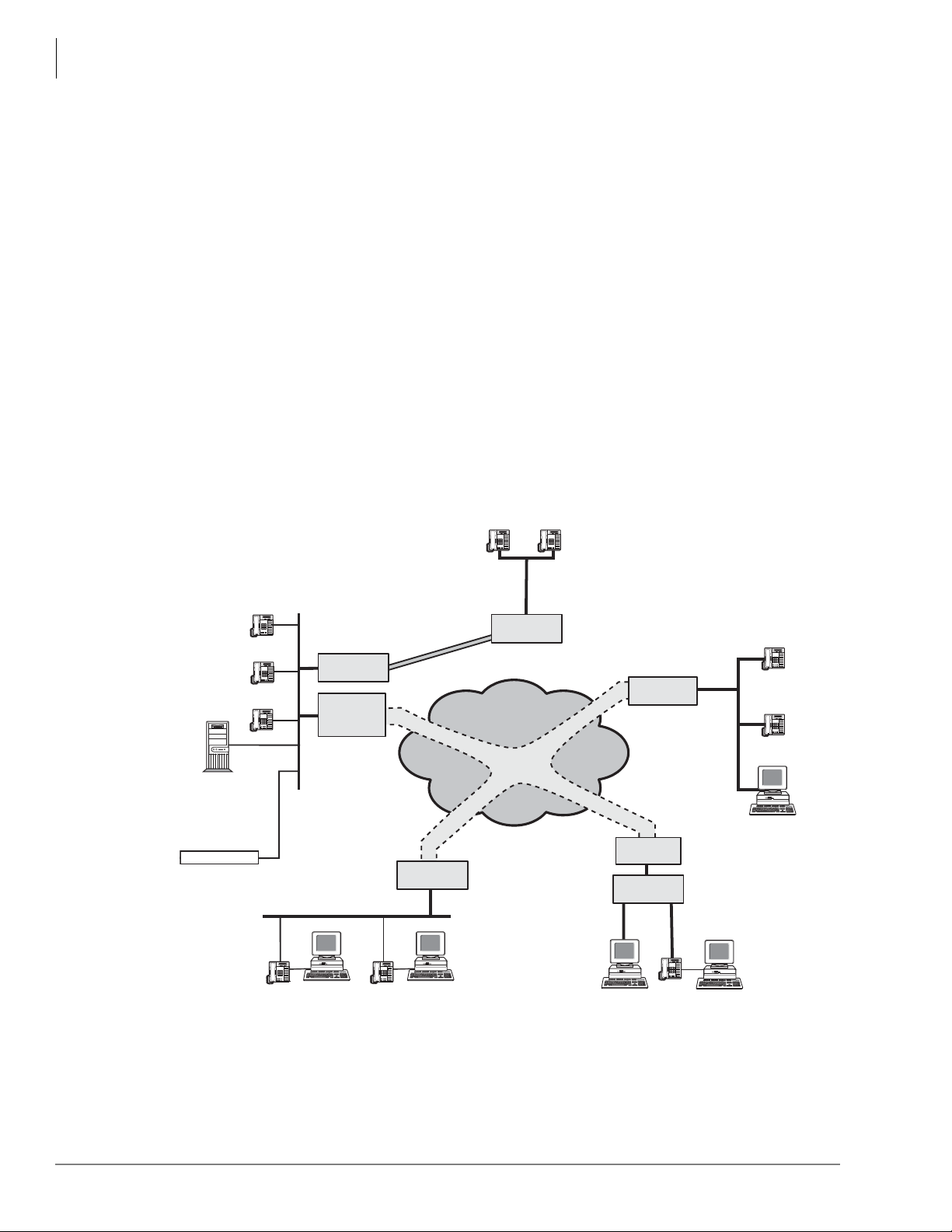
Unified Communications
IP User Mobility
When using home type xDSL or cable connections, only one or two IP telephones may be
connected because of xDSL and cable bandwidth limitations. Broadband is required when
installing two or more phones at a remote site.
An Internet configuration could use the following connections:
• No VPN, and thus, no security
• Third party VPN software residing on DHCP gateway server. T o conn ect IP telephones over the
Internet, using third party or Microsoft VPN software residing on a DHCP gateway server, see
Figure 8.
• ATM (IP over ATM virtualization by VC/VP)
• Broadband Ethernet virtualization by Virtual LAN (VLAN)
• IP-VPN (IP-VPN based on Multi-protocol Label Switching (MPLS)
• Private line connection
For an access line to link the user’s location with the access point of the carrier or provider , using a
private line, broadband line (xDSL, CATV), or fiber optics is recommended.
The IPT Anywhere feature enables remote IP telephone users working in branch offices or home
offices to make full use of the extension features of the IPedge. The diagram below shows IPT
Anywhere connections using the optional VPN connection.
IPT IPT
Satellite
Office
IPedge
Main Office
IPT
IPT
IPT
LAN
IPT
Router/
LAN Switch
VPN Router/
LAN Switch
or Server
Call Center
Contact Center
IPT
Private
Line
*
*
VPN Router/
LAN Switch
LAN
LAN
Router/
LAN Switch
IP Network
(Internet, Intranet, WAN)
VPN
Tunneling
xDSL, Cable,
*
T1, Fiber, etc.
*
VPN Router/
LAN Switch
Cable/
DSL Modem
VPN Router/
LAN Switch
*
IPT Anywhere
IPT
Satellite
Office
LAN
Home Office
0019-cix40a
IPT
IPT
Figure 8 IPT Anywhere Example
36 IPedge General Description 01/12
Page 51
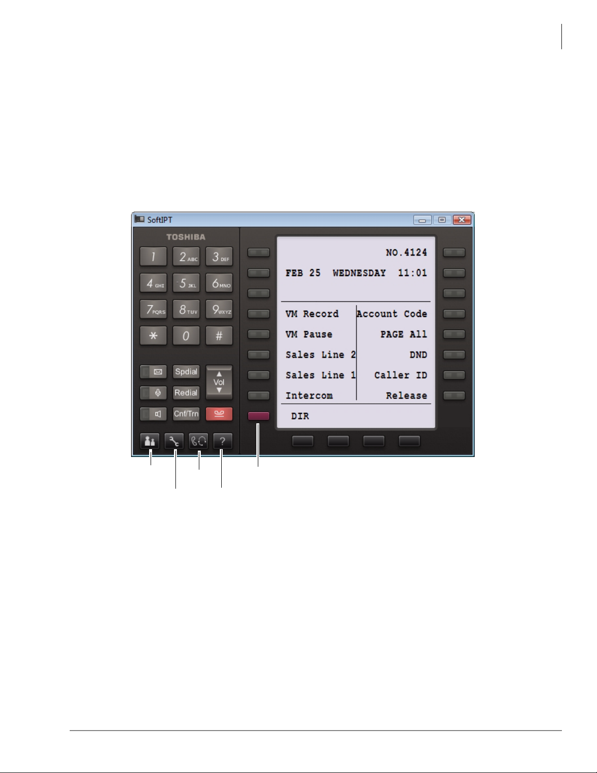
Unified Communications
SoftIPT
Configurations
SoftIPT
Directory
Audio
Settings
Help
Shift
Figure 9 T os hi ba SoftIPT Sample Screen
SoftIPT Client
The T oshiba SoftIPTTM is an IP telephony client that works with a wired or wireless (Wi-Fi) tablet,
laptop or desktop PC. The SoftIPT client on a PC integrates the power of the PC with most of the
features available on an IP5000-series telephone.
With the Toshiba SoftIPT installed on a Wi-Fi laptop PC, users can have true mobility with access
to voice mail, programmable feature buttons, and a directory that works with Microsoft®
Outlook®.
The T oshiba Soft Phone works on desktop or laptop PC with Microsoft Windows Vista, Windows
XP and Windows 2003 operating systems (OS).
The SoftIPT client looks similar to 5000-series telephones (shown below).
IP User Mobility
SoftIPT on a PC integrates the power of the PC with most of the features available on an IP5000series telephone.
The features supported by SoftIPT are:
• Self-labeling feature keys
• User control over feature button labels
• Shift key toggles the LCD screen between flexible key 1~10 and flexible keys 11~20
A mouse or stylus is used to click or select the buttons. There are multiple feature buttons that can
be customized from telephone programming mode.
IPedge General Description 01/12 37
Page 52
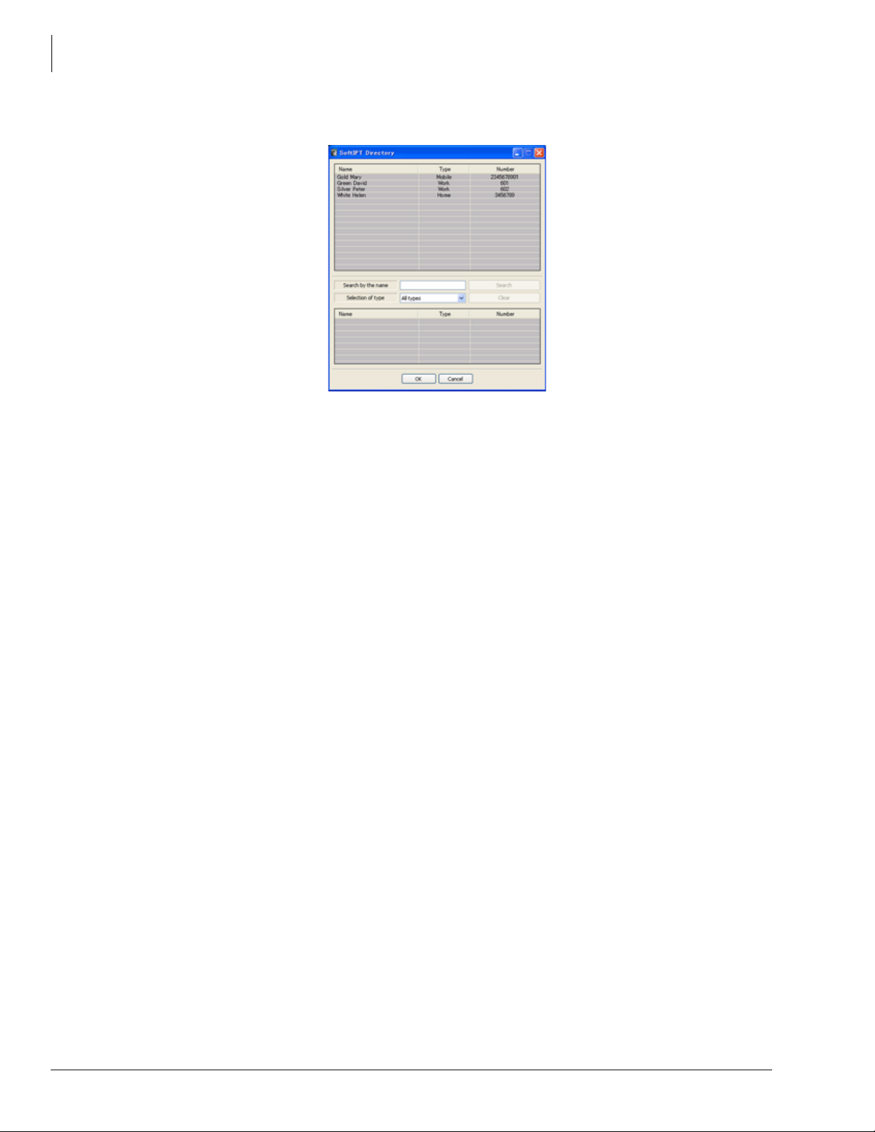
Unified Communications
IP User Mobility
With Microsoft Outlook, you can create a directory for the SoftIPT. Once a directory is created, the
user can click on a name in the directory to automatically dial their number (see Figure 1).
Figure 1 Example of SoftIPT Directory
The SoftIPT can be connected to the IPedge system in several different ways:
• Intranet – A wired or wireless PC can connect to the office LAN that connects to an IP
telephone.
• Internet – A wired or wireless PC at a remote site can connect to a Cable or DSL modem, to an
Internet Service Provider (ISP), to a router.
• Wireless – The wireless PCs or Toshiba Tablet PC need a Wi-Fi system. The SoftIPT wireless
units can operate within range of an access point (dealer-supplied or use existing).
Licensing
Refer to “IPedge Net and IP Telephone Bandwidth Requirements” on page 103.
38 IPedge General Description 01/12
Page 53

Networking 4
This chapter provides a description of the various network related configuration pieces that need to
be done when using VoIP networks and installing the IPedge system.
Preplanning for VoIP Deployment
Benefits
• More accuracy and predictability in estimating budget requirements (and TCO) for the VoIP
deployment by identifying network infrastructure needs up-front.
• Reduce cost of deployment by reducing trouble shooting costs.
• Reduce cost of post deployment maintenance and support by having the necessary information
before hand.
• Improve Project Management – All requirements and conditions for a successful VoIP
deployment are articulated, considered and factored prior to deployment.
Requirements
Network Assessment – A network assessment must be carried out to determine whether network
or service upgrades are required to support a VoIP deployment. Toshiba recommends carrying out
the network assessment with QoS enabled on the network.
Site Inventory Analysis – A site survey must be carried out to determine the list of network
devices required for a given deployment. This survey must include considerations for the
minimum required capability (feature set) and capacity for any networking device. A Gap analysis
must then be performed to determine what upgrades or purchases would be required to support the
deployment. The following table can be used for reference when doing Site Inventory Analysis.
Network Device Capability Capacity
Port Capacity
Switches QoS, VLANs, Autosensing, PoE
Routers QoS – DiffServ, DSCP 46
Ability to set firewall rules
Firewall and NAT
granularly.
Flexibility to translate based on
address and ports if required.
Port Bandwidth (GigE)
Throughput, Latency, Jitter
Uplink port Bandwidth
Throughput, Latency, Jitter
Throughput, Latency, Jitter
IPedge General Description 01/12 39
Page 54
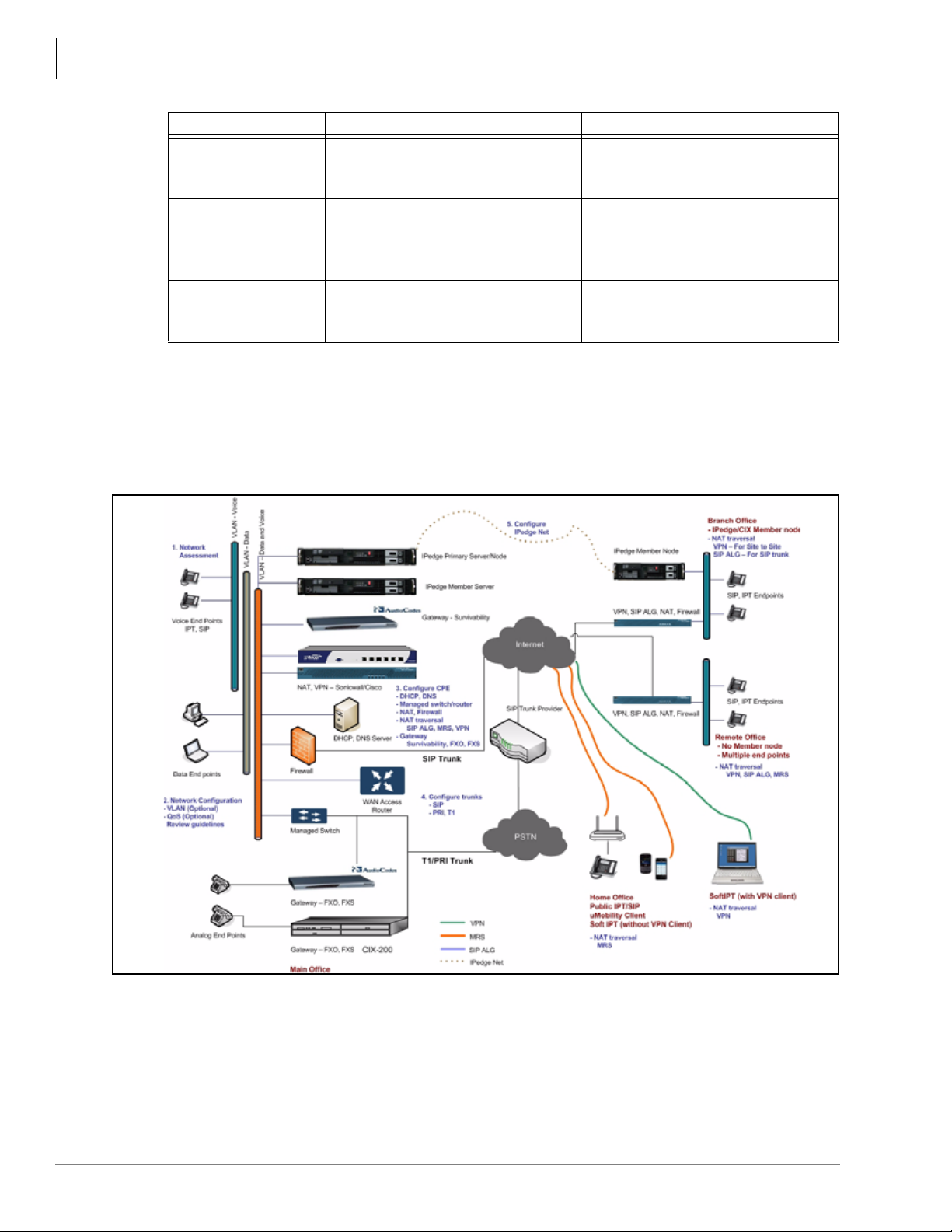
Networking
Preplanning for VoIP Deployment
Network Device Capability Capacity
SIP ALG
VPN Gateway
Server Platform DHCP, DNS, NTP Services
Site Network Diagram & Configuration – For networked VoIP deployments with multiple
IPedge or Strata CIX nodes, multiple trunk types or groups, one should document the network
topology in the form of a diagram (example shown below) along with configuration settings for
various network connectivity options (VLANs, IPs, IPedge Net, VPN, and Trunks etc). This
topology diagram along with the system connectivity configuration will serve as reference for
both, planning the initial deployment and for post-deployment maintenance, troubleshooting and
debugging activities.
Ability to successfully and
accurately transform all SIP/SDP
message headers.
Ability to create site to site
tunnels.
If required ability to create multisite VPN tunnels.
Throughput, Latency, Jitter
Throughput, Latency, Jitter
Capability to handle multiple
concurrent requests at high
performance.
Interactions
While most end customer deployments fit the Toshiba recommended network deployment model,
there may be instances where an end customer has unique network infrastructure or security
policies which necessitate custom configuration and deployment. As this can potentially increase
deployment time and effort it is critical to review end customer deployment environment and
policies as part of the planning process.
40 IPedge General Description 01/12
Page 55

LAN Deployment
LAN Deployment
Benefits
Cost savings from using and administering a single IP network infrastructure for both voice and
data communications.
Requirements
Core Network Characteristics for VoIP – In order to maintain voice quality, the underlying IP
network must satisfy the characteristics that are listed in the following table. The table lists
requirements for delivery over both Local Area Networks (LANs and WLANs) and for delivery
over Wide Area Networks (WANs).
Network Requirements (VoIP) Local Area Network (LAN/WLAN) Wide Area Network (WAN)
Reliability 99.99% uptime 99.99% uptime
Latency < 20 msec < 50 msec
Jitter < 10 (+/- 5) msec or less < 20 (+/-10) msec or less
Packet Loss < 0.1% < 1%
Network Bandwidth Capacity – The underlying IP network has to be provisioned so it can
handle the anticipated “maximum call volume”. To estimate this bandwidth, multiply the total
number of voice streams by the bandwidth per stream. Note each voice call is composed of two
voice streams, one in each direction. Bandwidth per stream = 88 kbps (G.711)
Networking
Network Assessments (MOS > 4.0) – A Network Assessment is required for every VoIP
deployment to confirm that the underlying IP network satisfies the requirement mentioned above.
The result of the Network Assessment must be a test report which qualifies the network for VoIP
readiness in terms of MOS scores. The minimum acceptable MOS score for acceptable voice
quality on an IP network is 4.0.
QoS Mechanisms – It is required that the network be designed to prioritize voice traffic over data
traffic as voice quality is very sensitive to packet loss, delay and jitter in the network. Depending
on the size of the implementation, one or both of these mechanisms is required.
• DiffServ (DSCP 46) – Enable DiffServ in the network switches and routers and in the phones to
prioritize voice traffic over data traffic.
• 802.1q (VLAN) – For larger deployments (> 100 IP Phones) create a separate V oice VLAN and
a data VLAN to limit the broadcast domain and minimize impact of data traffic on voice traffic.
Managed Switch or Router – It is necessary to ensure that the network is provisioned with
managed switches and routers which provide the following capabilities:
• Autosensing Capability – All L2 port connections must be configured for maximum possible
link (1000Mbps/100Mbps/10Mbps) speed and with full-duplex settings. The simplest way to
ensure this is to deploy switches and phones with “Autosensing” capability.
• QoS Mechanisms like 802.1q, 802.1p, DiffServ (DSCP 46)
• Power over Ethernet (PoE) – It is recommended that IP telephones be powered using the PoE
(IEEE 802.3af) technology. If PoE is not used, power bricks must be purchased separately for
each phone.
Static IP Addressing for IPedge – In order to ensure availability and security of the system, the
IPedge server and any gateways in the system must be provisioned with a static IP address on the
LAN. This process must be carefully managed to ensure that there are no IP address conflicts in
IPedge General Description 01/12 41
Page 56

Networking
LAN Deployment
the network. IPedge can be deployed with a private/static IP address, or it can be deployed with a
public/static IP address as long as it is still behind a firewall.
DHCP Server – A DHCP server must be installed and configured at each site in order to
automatically provision IP addresses for the IP telephones.
DNS Server – In an IP system a lot of the underlying communication relies on addressing hosts by
their fully qualified domain names (FQDN). In order for this communication to be successful host
names have to be resolved to IP addresses. For example, SIP trunking configuration uses URIs and
hostnames and these must be resolved to IP addresses using a DNS server. The IPedge server
requires that one FQDN be configured, and if IPedge meeting is being deployed, a second FQDN
is required.
NTP Server – It is critical that all networked devices (IPedge, gateways and IP phones) are
synchronized to the same clock (system time). The best way to do this is configure all of the
network devices to get and set their respective clocks from a public NTP server.
Firewall/NAT (Network Address Translation) Router – The IPedge server is designed to be
deployed, primarily in a private address space behind a Firewall and NAT router.
• In order to successfully deploy and manage the IPedge system the firewall rules need to be
configured to ensure that all valid incoming traffic is allowed by the firewall. For security
reasons, the firewall should be configured to deny all other traffic.
• One must configure NAT policies (both inbound and outbound) to map traffic for all IPedge
services between the WAN public IP address and the LAN IPedge private address. The details
on how the NAT policies and Firewall rules need to be configured are described in the
requirements that follow.
• Recommend network monitoring with a tool such as WhatsUp Gold, OpenNMS, and Zenoss
Interactions
Network Bandwidth Capacity – On a shared network infrastructure (both data and voice services),
one needs to consider bandwidth requirements for both data and voice.
To provide additional prioritization for voice services, it is possible to enable 802.1p in
conjunction with 802.1q (VLANs). This is currently a system wide setting in IPedge. However,
this will enable 802.1p on remote phones requiring the switches are all locations where remote
phones are deployed to support 802.1p.
For IP telephone configuration, broadcast mode is not recommended for large deployments
(greater than 100 phones).
®
.
42 IPedge General Description 01/12
Page 57

Remote Administration
Benefits
Gives an administrator the ability to manage the system from a remote location, thereby saving
time and money.
Requirements
In order to manage an IPedge system from a remote location, any of the following mechanisms can
be used.
HTTPS – This is a standard web based method to securely access and administer the IPedge
system from a remote location. In order to use this mechanism:
• Configure the Firewall to allow bi-directional HTTPS traffic.
• Configure NAT router to forward HTTPS traffic on a given port to the IPedge HTTPS service
(TCP port 9443)
• Configure the Firewall to allow and NAT to forward TCP ports (10000, 9101-9103)
• Configure certificate on the IPedge system for HTTPS authentication
• Setup a FQDN for the IPedge server in the DNS server.
Networking
Remote Administration
IPSec VPN – An IPSec VPN session is setup so an administrator can log on to the network and
administer the system directly. The VPN session must be configured with sufficient privileges to
enable access to the IPedge system.
Firewall and NAT Configuration – This method relies on manual configuration of the Firewall
(allow inbound management traffic) and the NAT router (forward inbound management traffic to
IPedge) to allow remote access to the IPedge system from a specific IP address or group of IP
addresses. The following ports need to be opened and forwarded for remote administration
purposes, from specified IP addresses:
• HTTP – TCP port 8080
• Webmin – TCP port 10000
• BACULA – TCP ports (9101 - 9103)
Interactions
Port Forwarding – In some instances and deployments the standard ports used by IPedge may also
be used by other systems and/or services within a deployment. One can also encounter this
situation if there are multiple IPedge nodes within a single LAN. When one encounters such
situations it would be necessary to use NAPT (Network Address and Port Translation) instead of
standard NAT (Network Address Translation only) translation, to enable remote administration.
IPedge General Description 01/12 43
Page 58

Networking
Centralized Administration
Centralized Administration
Benefits
Centralized administration allows multiple nodes to be managed through a single point, reducing
the time it takes to administer multiple servers and also reducing the possibility of missconfiguration.
Requirements
• VPN – A VPN is required between sites that implement Centralized Administration in order to
provide for security of the administration information.
• Multi-node Centralized Administration – The IPedge system enables administration of a
multi-node system from a single node called the Primary Server. In order to enable this unified
administration the following SNMP ports need to opened and forwarded on the Firewall and
NAT router (at each site that is being administered) respectively.
• SNMP – UDP ports (161-162)
Interactions
For most centralized operations an administrator will connect to the primary node. For some
interactions, like setting the IP address on a remote node/server, th e web browser will be redirected
to the specific node/server. To allow these functions it is necessary to configure the Firewall and
NAT rules at the remote node as documented in the “Remote Administration” section above.
IPedge Net
Benefits
A system with multiple independent IPedge nodes (and associated end points) can be logically
unified by networking the individual nodes together using IPedge Net. The primary benefit for
doing this is visibility and connectivity between any two end points irrespective of what node they
are connected to.
Requirements
• IPedge Net – From IPedge Enterprise Manager, IPedge Net connections need to be setup
between all the connected nodes.
• VPN Connection – If the individual nodes to be connected are separated across a public
network (Internet/WAN) a VPN connection needs to be setup for a successful IPedge Net
connection to be established between these nodes.
Interactions
IP Packets from phones on different IPedge Net nodes are relayed though the IPedge server; IP
packets for these communications are always sourced from one nodes IP address and destined to
the other node’s IP address. If these nodes are behind a firewall this communication would need to
be allowed.
44 IPedge General Description 01/12
Page 59

Remote IP Telephones
Benefits
• Small office or Home office users can be connected to their work phone system.
• When using SoftIPT, enables Road warrior scenarios.
Requirements
In order to connect a remote IP telephone (or SoftIPT) to an IPedge node, either of the following
mechanisms can be used:
Media Relay Server (MRS) – Within the Firewall and the NAT router at the main office, the
following ports need to be opened and forwarded; in order for the remote IP telephone to
communicate to the IPedge system:
• H.225 – UDP (1718 – 1719)
• Megaco – TCP 2944
• Media Relay Server – UDP port range (21000 - 22999)
• FTP, FTP Data – TCP ports (20-21)
Networking
Remote IP Telephones
IPSec VPN – An IPSec VPN session needs to be setup between the remote location and the main
office. In case of a SoftIPT the IPSec VPN connection is established by a soft VPN client back to
the main office.
Interactions
• When using MRS, most home office and small office routers require no configuration in the
firewall and NAT locally as they tend to initiate the connection and save state for the inbound
connection. In some cases this may not work and the ports references in Requirement 1 may
also have to be opened on the home router.
• Using the MRS the IPedge system dynamically and automatically configures port forwarding
rules for any NAT traversal related issues. If, for some reason a remote IP telephone still cannot
register due to local NAT router issues, configure the remote IP telephone’s station
programming to use the Static MRS parameter. This will resolve any NAT issues that prevent
registration of the IP telephone.
IPedge General Description 01/12 45
Page 60

Networking
Remote SIP Phones
Remote SIP Phones
Benefits
SIP end points provide the ability to use application specific devices such as door phones, wireless
devices, paging systems, etc.
Requirements
In order to connect a remote SIP end point to an IPedge node, any of the following mechanisms
can be used:
• SIP ALG (Application Layer Gateway)
• A SIP ALG device needs to be configured at bo th the main of fice and at the remote location
to transform the SIP/SDP session header addressing information.
• Firewall and NAT configurations to allow and forward SIP – UDP port 5060 to the IPedge
system.
• Media Relay Server (MRS) – If a SIP ALG does not operate as desired, the MRS function
within IPedge can be used to get a remote SIP end point registered with an IPedge node. T o use
this method, within the Firewall and the NAT router at the main office, the following ports need
to be opened and forwarded; in order for the remote SIP end point to communicate to the
IPedge system:
• SIP – UDP port (5060)
• Media Relay Server – UDP port range (21000 - 22999)
• IPSec VPN – A remote SIP end point can also connect to an IPedge node over an IPSec VPN
connection.
Interactions
When connecting SIP devices across routers, some home routers implement SIP application layer
gateways. To work successfully, these gateways need to be configured to enable SIP
transformation. However, not all application layer gateways work consistently and if a given
gateway does not work, it should be disabled and the IPedge Static MRS function can be invoked
to still support these end points.
46 IPedge General Description 01/12
Page 61

SIP Trunking
Benefits
• SIP trunking is one of the most cost effective ways for an enterprise to provide voice services
for their users.
• In an increasingly data networked environment, it offers enterprises the ability to use their
existing data network to offer both voice and data services; thereby simplifying and
consolidating the costs associated with maintenance and administration of two separate
networks.
Requirements
• SIP trunking service – SIP trunking service needs to be purchased from a Toshiba certified SIP
trunk provider.
• Configure SIP trunking on IPedge node – SIP trunk parameters provided by the service
provider need to be configured within the IPedge administration interface in order to register
with and use the service.
• Within the Firewall and the NAT router the following ports and protocols need to be opened
and forwarded; in order for local end points to communicate and make calls via the SIP trunk
service:
Networking
SIP Trunking
• SIP – UDP 5060
• R TP/RTCP – Dynamically assigned
• SIP ALG (Application Level Gateway) – The firewall that the IPedge server sits behind must
support a SIP ALG or SIP traversal function in order to properly transform SIP packets as they
traverse the firewall. Usually the setup for this involves turning on the function in the firewall.
Interactions
Different SIP trunk providers have different configuration requirements to enable the service.
There are variations in requirements around registration, authentication, ports used, SRV records
etc. For details and references on configuring SIP trunk programming for these different
variations, refer to the IPedge Install Manual.
IPedge General Description 01/12 47
Page 62

Networking
Web Conferencing
Web Conferencing
Benefits
Gives users across geographic boundaries the ability to do audio and web conferencing on
demand. This is helpful for purposes of collaboration in distributed team environments; attendees
from different locations can view and work on the same information in real time by using features
such as desktop and document sharing.
Requirements
• Within the Firewall and the NAT router at the main office, the following ports need to be
opened and forwarded, in order for a participant to access the IPedge Meeting conferences:
• Admin – TCP 80
• Secure Admin – TCP 8444
• Web conferencing – TCP 443
• Data port for desktop screen sharing service – TCP (1935, 1945)
• DNS Server Configuration – In order for the IPedge Meeting service to be easily and publicly
(from the WAN) accessible, a couple of fully qualified domain names (FQDNs) need to be
created. These FQDNs need to be mapped via the DNS service to the IP address of the IPedge
Server. FQDN mappings within the DNS service (server) need to be created for:
• Meeting administration service
• Meeting web conferencing service
Note If the IPedge server is deployed behind a NAT firewall, the DNS service would need to be
configured to map the FQDNs to the NAT public IP address instead.
Interactions
In some IT environments, public facing services and servers are configured in the DMZ. If that is
the case in a customer deployment, firewall and NAT rules will need to be configured for IPedge
meeting services to be accessible from both the WAN and the LAN.
48 IPedge General Description 01/12
Page 63

Contact Center 5
An external Automatic Call Distribution (ACD) software option with the IPedge is provided by
connection of an external PC-based CTI application server or as an application on the Media
Application Server (MAS). The CTI server runs both the ACD call processing application and the
separate Management Information System (MIS) application such as Insight, as well as other CTI
applications.
The ACD application is available in Basic and Enhanced feature functionality, along with the
number of groups and active agent size increments to provide cost-effective pricing levels
according to the user’s needs. Enhanced ACD includes all basic capabilities plus multiple group
login, skills-based routing, priority queuing, time scheduled ACD queues, agent and call priority
escalation handling, and balanced call count agent search. For more information regarding ACD,
ACD Licensing, etc., refer to the IPedge Contact Center General Description.
Basic ACD Features
Advanced Call Routing
The optional Call Router enables calls to be routed based upon parameters such as Caller ID,
account numbers, private lists, time-of-day, day-of-week, day-of-year, and user entered data
(account code, etc.). This is an optional feature that can be added to the ACD application.
Intelligent Announcements
The holding caller can be informed of call status, such as their place in queue or estimated time
before an agent answers. The intelligent announcement function can also offer alternative options
to continuing to hold, such as going to voice mail.
IVR Voice Assistant Open Database Connectivity (ODBC) Access
There are two options that can be used with customized services: Interactive Voice Response
(IVR) Voice Assistant (VA) application can be used as a stand-alone product and/or as an IVR
service to the ACD application. For example, an IVR port could be used to do an external page to
alert agents to return and login to an ACD queue when it gets too overloaded with calls.
Other useful functions include gather and validate user input, play menus and act on response, and
trigger other events. The IVR VA can also be used to provide low cost text to speech capabilities.
The IVR VA is an optional feature that can be added to the ACD application.
IPedge General Description 01/12 49
Page 64

Contact Center
Enhanced ACD Features
Enhanced ACD Features
Agent Priority Routing
The Agent pool can be expanded when traffic gets heavy based upon agent priority levels. When
all agents are busy at one level, calls automatically get distributed to agents at the next level. Calls
can be distributed by agent priority, preferred agent treatment, or balanced call count.
Multiple Group Agent Login
ACD agents can be logged into multiple ACD groups, enabling agents to answer calls for multiple
groups. This is very useful for back up coverage between groups. It is also the foundation for
skills-based routing and agent priority routing, enabling many advanced call center applications.
Skills-based Routing
Based on the caller’s input, the system can route the call to the agent best suited to handle the call.
Calls can be routed to certain agents, based upon agent capabilities, in addition to Dialed Number
Identification Service (DNIS), CO line, or Auto Attendant routing into different groups. With the
capability for agents to log into multiple groups, calls can be routed to different agents based upon
skills needed for each specific call.
Priority Queuing
ACD calls can optionally be tagged with a priority number before they are placed into the ACD
group queue. The priority number assigned to the call determines where the call is placed in queue.
This feature enables high priority calls to be answered sooner than low-priority calls. The
escalation parameter ensures that no call is lost due to higher priority calls.
Web-based Contact Center
Multimedia Contact Center application uses web technology to increase the customer’s reach by
providing web surfing customers with the option to contact the contact center.
Web Callback
The Web Callback service enables users to place a callback request from the customer’s website.
This service gives users easy access to the contact center via the web. Most types of browsers are
supported, including on the Mac
The Web Callback service easily integrates with a customer’s existing web pages. This service is
set up similar to the current voice based callback and the call center has the same ability to
generate reports they currently use.
Chat Contact Center
Chat is a semi-realtime communication method which adds another media of the communication
to users. For example, if a Technical Support person needs to spend some time to investigate a
question from the user, the user can continue to surf the web while waiting for the response from
the Technical Support person. Sales groups can assist users in placing orders while the user is on
the web page.
®
.
50 IPedge General Description 01/12
Page 65

Features 6
This chapter contains the IPedge features. They are presented in alphabetical order to make it easy
to locate each feature.
Account Codes
Account Codes are often used for cost allocation of the call or the time the caller was
involved on a phone call. The codes are printed on a Station Message Detail Recording
(SMDR) printout along with other call details so that the customer can identify all calls
associated with a specific account code.
Account codes may be forced (required after dialing all or specific phone numbers) or voluntary (optionally entered anytime during calls). Codes can be as long as 15 digits and can
be verified or non-verified by the system.
Add-on Module (ADM)
One to two LM5110's (10 button) can be attached to IP5000-series telephones to provide
an additional 20 programmable buttons.
One to two KM5020's (20 button) can be attached to the IP5000-series telephones to provide an additional 40 flexible buttons.
ADM buttons can be programmed with outside line or Directory Number buttons, Direct
Station Selection, One Touch Speed Dial or any other flexible feature button.
Advisory Message
Any IP5000-series telephone user can set a message on his or her telephone. Whenever
another IP5000-series telephone with a display calls a station with a message set, the
information in the message displays on the calling station’s LCD. This feature allows
users to define their current status and make that status available to others attempting to
call that person. This status is also sent to Attendant Consoles.
IPedge General Description 01/12 51
Page 66

Features
Alarm Notification
Alarm Notification
IPedge can send alarm notifications to a Monitoring PC/Server or send an alarm notification to a telephone.
System alarms can be sent to up to three unique IP addresses from IPedge SNMP traps.
Alternate Answer Point
Users can answer a transferred internal or outside line call from any station that has a
Directory Number button appearance of the “transferred to” Directory Number.
Automatic Busy Redial
Automatic Busy Redial (ABR) enables a telephone user to automatically redial a busy outside number multiple times at programmed intervals. Each station may only have one call
registered with ABR at any time.
Automatic Call Distribution (ACD) Server
See Chapter 5 – Contact Center for details.
Automatic Callback (ACB)
When a station user dials a busy station DN or outside line access code and receives a
busy tone, Automatic Callback (ACB) can be activated by pressing an ACB feature Soft
Key or by dialing 4. When the busy DN or outside line becomes available, the station will
be automatically called back and be connected to and ring the originally called station or
receive a dial tone from an outgoing line.
When ACB is activated, the calling station receives a success tone followed by a busy
tone. Once ACB is activated, the caller can hang up. ACB can be canceled any time using
an access code. It will also cancel automatically after a predetermined time.
Automatic Line Selection (ALS)
This feature automatically connects a telephone to a specific line or extension button when
the user lifts the handset off-hook, presses the Spkr (speaker) button, or presses a digit on
the dial pad (Hot Dialing). This feature is necessary to make telephone operation consistent for the user because a telephone can have up to 20 line and extension buttons. Each
telephone can be assigned in system programming with various options that determine
what type of line or extension button is selected when the user takes the handset off-hook
to make or answer calls.
52 IPedge General Description 01/12
Page 67

When answering calls, this option can be set to answer the call or not when a call rings the
telephone and the user takes the handset off-hook. If the option is set to not answer automatically , the user can press the ringing butt on on the telephone to answer manually. With
Automatic line selection, if more than one type of call is ringing simultaneously on the
telephone, this option selects which type of call should be answered as a priority, then the
longest ringing call in that call type is answered first.
Automatic line selection options are set independently for each telephone, for originating
new calls and answering ringing calls. This feature can also be disabled on all or selected
telephones to allow users to manually press a button to originate or answer calls.
Background Music (BGM)
Background music audio can be played through the speakers of IP5000-series telephones.
IPedge Net supports up to 15 BGM WAV files. Selection of the BGM source to be played
can be done individually by each telephone user and for each external page zone using
Enterprise Manager.
Features
Background Music (BGM)
Call Completion
This feature applies when calls are not completed because the station does not answer, is
busy , or is in Do Not Disturb. A series of options are available to the user when encounter ing these conditions. They include changing the calling signal from Voice Announce to
Ringing or vice versa, setting Automatic Callback, setting the Message Waiting light,
Camp on Busy , Overriding the condition with Privacy/DND/Executive Overrides, or using
Off-Hook Call Announce.
These options are easily activated by dialing a single digit code or pressing a soft key
when the condition is recognized. These options are individually set for each telephone to
be able to activate the call completion feature and to permit the feature to be activated
when called.
Call Forward
Call Forward can be activated and deactivated for every DN (PDN, PhDN, Station Hunting pilot number). Call Forward cannot be activated and deactivated for the GCO key, but
the call forward is applicable to the PDN of the station having respective ownership.
When an incoming trunk call terminates at a DN key or GCO key and Call Forward activates at both keys, the call forward at the DN key has priority. The call forward (that is,
PDN for the station having Ownership) on the GCO key is ignored, regardless of the type
of Call Forward activated.
This feature can be set and reset for the DN (PDN, PhDN, Station Loop, extension pilot
number).
IPedge General Description 01/12 53
Page 68

Features
Call History
This feature can be set and reset (local/remote) from an IP telephone, attendant console, or
using Enterprise Manager.
Call History
Incoming calls with Caller ID or ANI information may be optionally recorded into a rolling list for the station where the call is ringing. The call is placed in the list along with the
number, name (if provided), time and date of the call, and status of the call (answered,
abandoned, or redirected). This list is accessible by the user from the telephone LCD and
any call may be selected and redialed using the flexible Caller ID or Hist button.
When calls ring a button (Line or DN) that appears on multiple stations, the number is
stored on the telephone that is designated as the owner of the Line or DN and on the telephone that answers the call. If an incoming call is directed to a telephone, but the call is
not answered by that telephone because it hunts or forwards to another destination, the call
record is still stored on that telephone as “redirected” and on the telephone that answers
the call as “answered.” If a call is not answered, it is stored on the line or DN owner’s telephone as “abandoned.”
To store call records, a telephone must be allocated Call History memory by the System
Administrator.
Call Manager
The Call Manager features are covered in Chapter 3 – Unified Communications.
Call Park
Call Park gives any station, regardless of type, a method for holding calls. By parking a
call, you are free to make other calls and retrieve the call at a later time or use the paging
system to announce a call to be picked up by someone else on the system. Any call can be
parked. Parking a call to your phone is known as Local Park, parking a call on someone
else’ s phone is known as Remote Park, and if a general orbit is used, it is called Auto Park.
Call Park Orbits
The Call Park feature enables a station user to place a call temporarily in an orbit so that
the call can be retrieved by any user, either from the same station or from a different station. Personal Park Orbits are available to any type of telephone, including standard telephones. If a call is parked, but not retrieved within a preprogrammed time period, it will
recall the parking telephone. The Park Recall timer is a system wide timer setting.
54 IPedge General Description 01/12
Page 69

Park and Page
This feature enables station users to park a call (in a General or Personal Park Orbit), enter
a Page Zone or Group access code, and then announce the orbit number of the waiting call
to the Paged party . A pre-programmed One Touch button can be assigned to telephones to
automatically connect to a predesignated External Paging circuit, a Telephone Paging
group or both.
Call Pickup
Call Pickup enables station users to pick up all types of ringing or held calls including
internal, PDN or PhDN calls ringing or on hold at other stations. When you pick up an
internal call, the calling station and the called station displays on your LCD.
Group Pickup
Two or more stations can be assigned to a pickup group, there are a total of 48 pickup
groups available. You can easily pick up ringing calls on other extensions. Ringing calls
include: new, transferred, internal, or external calls. You will have the ability to pick up
calls for other extensions in your group and other groups as well. See your system administrator for group assignments.
Features
Call Pickup
Ringing, Page, or Held Call Pickup
This feature picks up ringing or held calls, including Group Page and All Call Page calls.
If these types of calls occur at the same time, the pickup priority is station-to-station and
then Page calls in the order of occurrence. In some systems, this feature can be applied to
pick up All Call Page exclusively.
Call Transfer
Call Transfer is the ability to redirect a connected call to a new destination. IPedge Net
provides three means of transferring a call and three means of terminating transferred
calls, depending on the calling state of the destination. The transferring features and the
terminating features may be used in combination to serve most needs that arise.
Music or Ringing Option
This feature enables ringing or music to be heard by the caller when their call is transferred, depending on system programming.
Transfer With Camp On
This feature enables the transfer of a call to a busy destination. The transferred party automatically camps on to the busy destination when the transferring party releases the call.
Transfer Immediate
Call Transfer Immediate simplifies the transfer of calls for users of IP telephones. With a
conversation in progress, the display phone user presses the
IPedge General Description 01/12 55
TRNS Soft Key and dials the
Page 70

Features
Call Transfer
transfer destination. The calling party is placed on Consultation Hold, the call immediately transfers and the transferring phone returns to idle. This feature does not apply to
network calls.
Transfer Privacy
An outside call that has been transferred can only be answered at the station where the call
has been transferred. Another station cannot pick up the transferred call unless it is another
station using the Directed Call Pickup feature or a station that has a DN appearance of the
“transferred to” DN. A flashing red LED indicates the call is transferred. Privacy for transferred calls can be disabled in programming.
Transfer (Screened)
The transferring party can talk privately with the receiving party before connecting the
party to be transferred. While that conversation is going on, the transferred party is on
Consultation Hold listening to Music-on-hold. When the receiving party agrees to accept
the call, the transferring party can use the switch hook or feature button to include the
original party in the conversation. At this point, the transferring party can hang up and the
other two parties remain connected.
Transfer (Unscreened)
Unscreened Transfer allows the transferring party to exit the connection before the transfer destination answers. After the destination answers the call, the system treats it as a regular call. If the destination does not answer the call within the predetermined time period,
the transferring party is recalled.
Transfer to Voice Mail
The transferring party can transfer a call directly to a person’ s voice mailbox without waiting for the call to forward from the called party’s telephone. The voice mailbox does not
need to be associated with an active telephone in the IPedge Net system. Direct transfer to
voice mail (VM) can be performed to a centralized VM system connected to a network
node other than the user’s node.
The transferring party presses
Direct Transfer to VM and dials the mailbox number , and
the call transfers immediately on receipt of the last digit. The transferred party hears the
greeting associated with the specified mailbox and can then leave a message.
Direct Transfer to Voice Mailbox simplifies getting a call for a busy or absent employee to
his/her mailbox. It eliminates the need for the caller to enter the desired mailbox number
after being connected to the voice mail system. This feature is available using standard
DTMF VM integration and does not require Toshiba proprietary VM integration.
56 IPedge General Description 01/12
Page 71

Call W aiting
When a station is busy with a call and another call is directed to that station’ s busy Line or
DN button, two short beeps are issued to alert the telephone user of the pending call.
Call Waiting works for calls originating from within or outside the system. The length of
the Call Waiting beeps is different for internal and external Call Waiting. The different
beeps distinguish which type of call is waiting.
Caller ID, DNIS, or ANI information appears on LCD telephones for 10 seconds. If Caller
ID information is not available, the device name, such as the SIP trunk or DNIS name or
number is shown.
IP telephones receive a Call Waiting tone twice from the handset receiver. Call Waiting
tones can be turned off on each station by the System Administrator.
When a station is busy with a call and another call is incoming, a tone alerts the caller of a
pending call. On LCD telephones, the Caller ID information displays for 10 seconds. The
combined effect of the Call Waiting alert tone with the displayed information enables
users to identify whether or not they want to interrupt their current call for the waiting call.
Features
Call Waiting
To answer the Call Waiting, the current call must be parked, terminated, or transferred.
Multiple calls can be queued to a single station, all waiting for that station to become free;
the call at the head of the queue provides the Call Waiting signal and LCD indication.
The tone (two beeps) signaling Call Waiting tone is provided through the speaker of the
phone. Caller ID display is not available with standard telephones.
Caller Identification
Caller Identification (Caller ID) is the general term for the information provided identifying the originating party of a public network call. The name and telephone number of the
calling party displays on the ringing telephone’s LCD. Incoming calls with Caller ID or
Automatic Number Identification (ANI) information may be optionally recorded into a
rolling list for individual stations. Station users with LCD displays can access this list to
select and redial these calls (Call History).
Caller ID lists can include the number, name (if provided), time and date of the call, and
status of the call (answered, abandoned, or redirected). Digital stations are assigned memory for creating the Call History.
ISDN Calling ID Name and Number
Both Caller ID name and number are supported, if available from the service provider.
IPedge General Description 01/12 57
Page 72

Features
Class of Service
Class of Service
The Class Of Service allows or denies a user to access the particular feature or determines
to what degree the user is serviced. A station (IPT/ SIP terminal/ SLT) and an attendant
console have their own Class Of Service. Regarding an incoming call, the Class Of Service is either assigned to a line on programming base or assigned to a call on call by call
basis.
The Class of Service consists of four specific parameters:
• Class of Service (COS) is used to check if a station or port is entitled to access a feature.
• Destination Restriction Level (DRL) is used by the Toll Restriction feature to check if the
calling party is allowed to make a call to the dialed external destination.
• Facility Restriction Level (FRL) is used by the Station CO Line Access to check if the calling
party is entitled to access the trunk facility.
• Queuing Priority Level (QPL) is used by the Automatic Callback feature and the Off Hook
Camp On feature to determine the queuing priority of the calling party.
COS is used to check if a station or port is entitled to access the feature. DRL is used by
the Toll Restriction feature to check if the calling party is allowed to make a call to the
dialed external destination. FRL is used by the Station CO Line Access feature to check if
the calling party is entitled to access the trunk facility. QPL is used by the Automatic Callback feature and the Off-hook Camp On feature to determine the queuing priority of the
calling party.
The COS is always referred against the configuration table, while the DRL/FRL/QPL are
referred with their numeric values. Thus, the numeric value of COS is just an index. In
addition to the COS index, the station profile may be used to represent more detailed and
complex information of allowance/denial of stations. As for the DRL/FRL/QPL, the larger
value has higher priority than the smaller value. The COS takes indexes 1 through 32
while DRL/FRL/QPL take levels 1 through 16.
Conference Call
Conference calling enables other people to join your conversation. These additional people can be inside or outside the IPedge system. Any station can set up a conference with
other stations or outside lines. A conference is defined as any time three or more parties
join into one conversation. A maximum of eight parties are allowed into a conference with
up to six from outside lines or standard stations. The originator of the first conference is
the “master” and controls adding and deleting conference parties. The conference “master” can drop off the last added party by using the Cancel button.
Conference On-Hold
A conference call may be put on Hold so that all the remaining conferees remain connected and no Music-on-hold is applied. The person putting the conference on hold may
rejoin the conference by pressing the Line button on their phone. The Hold state of the
58 IPedge General Description 01/12
Page 73

Credit Card Calling
conference can be released from another station by pressing the Line button of that station. At this time, the station that released the Hold state becomes Conference Master . This
enables one person to establish a conference call for others.
Split/Join/Drop
This feature enables the conference master to add (Join) other phones to a conference. The
conference master and another member of the conference can leave (Split) the conference
for a private conversation. During this time, other conference members remain connected.
The conference master can then Join both of the Split callers back into the conference, or
the master can Drop (disconnect) the Split member he/she is connected to.
Releasing from Conference Tandem SIP Trunk Connections
This feature enables unattended line-to-line connections for the IPedge system, freeing the
conferencing station or voice mail port for other calls and important tasks. When a tandem
connection is set up with a DN button, the DN button will go idle after releasing from the
connection. The DN can then be used to make or receive calls from the originating telephone.
Features
Telephones and/or VM devices can establish tandem SIP trunk connections and then
release from them without disconnecting the tandem connection in the IPedge system.
After releasing from a tandem call, reconnecting to the call can be accomplished by dialing an access code.
Whether or not tandem line buttons appear on a telephone, the telephone user can enter the
connection and release the line that was connected to the original line or release both lines
by pressing the Cancel button.
Voice Mail Conference
Voice Mail ports may be included in conference calls. This enables all members of the
conference to listen to and play voice mail messages.
Credit Card Calling
Callers can make “0+” telephone credit card calls from selected toll restricted stations.
When dialing from toll restricted stations, if the caller does not enter a credit card number
after dialing “0,” the call will be disconnected.
Calls are billed to the credit card instead of the IPedge Net line. The “0+” credit card calling feature can be enabled selectively or assigned to stations and CO lines capable of supporting this service.
IPedge General Description 01/12 59
Page 74

Features
Day/Night Mode
Day/Night Mode
Auto Schedule – The system has three operating modes that are based on the time-of-day ,
day-of-the-week, and up to 128 holiday schedules. The operating modes are Day1, Day2,
and Night. Each mode controls the routing of incoming line calls and settings for station
and line Class Of Service restrictions. The system can be programmed to use all three
modes, Day/Night mode only, or just the Day mode. The system switches automatically
from one mode to the next based on the system’s time-of-day clock.
Example Day/Night Mode Applications:
Incoming Calls
trunks via a gateway, SIP trunk URIs, and individual DID and DNIS numbers can change
their ringing destinations automatically according to the date and time of day.
For example: On workdays, calls are routed to the attendant, individual telephones, ACD
groups, etc., until 5:00 p.m. After 5:00 p.m., calls are routed off-premise to another office,
to the Night Bell, or to night announcements and voice mail message boxes. On holidays
and weekends, calls are routed independently to the appropriate holiday announcements or
voice mail message boxes.
– Incoming line call including ground/loop start lines converted to SIP
Class Of Service – Station, lines, and DID numbers are assigned options in Class of Ser-
vice. These include Toll Restriction, Override privileges, allowed tandem connection,
security code administration, etc. Any of these options can be changed independently for
each telephone, line and DID number when the system switches from one operating mode
to another.
For example: When the system changes from the Day to Night mode, selected stations can
be automatically restricted from dialing outside or long distance calls. Note that outgoing
route selections set in LCR are switched using a route selection schedule that is independent of the Day/Night mode schedule.
System Call Forward – The System Call Forward settings for stations can be changed
automatically when the system changes from the Day to Night mode. For example: During
the day , a telephone can forward to a person’s car or cell phone, and at night automatically
forward to the person’s voice mailbox.
Tenant Services – Up to eight different tenants can each have different attendant or night bell
assignments for day-of-the week schedules using Day 1, Day 2, or Day 3 modes. This feature is
enabled in system programming.
Manual Mode Change – The system also enables users to manually change the Day/
Night operating mode, even if the system is using the Auto Schedule feature. A
Transfer
key can be set on telephones for manually switching at any time from one mode
Night
to another. The key’s LED flash rate indicates the system’s operating mode.
60 IPedge General Description 01/12
Page 75

If used with the System Auto Schedule operation, the Night Transfer key overrides the
current Auto Schedule mode. However, when it is time for the system to switch to a nother
mode per the Auto Schedule timer, the system will switch to the mode set by the Auto
Schedule.
Example: If the system is switched from Day to Night at 2 p.m. manually with the Night
Transfer key (Auto Schedule is set to switch from Day to Night at 6 p.m.), the system will
still automatically switch back to the Day mode at 8 a.m. the next morning per the Auto
Schedule.
Dial Directory
Station users can dial by name using Toshiba’s IP5000-series LCD telephones. The Dial
by Name feature searches for names much like a cell phone directory and then allows the
user to press one button to dial. This feature includes speed dialing and internal directory
names. Your telephone will display names (First Name, Last Name or vice versa) depending on the way they have been programmed in the telephone system. All directory names
are sorted alphabetically . Individuals stations and speed dials can be omitted from the Dial
by Name directory if desired.
Features
Dial Directory
Direct Inward Dialing (DID)
This feature allows external callers to dial directly to individual extensions or groups of
telephones without intervention by an operator, IVR, or auto attendant. Each incoming
DID number can be routed individually to an extension, pooled or group line button, ACD
group, maintenance modem, external page, night bell, voice mail box, or back out over the
public or private telephone network. DID routing assignments can change automatically
when the system switches between the Day and Night Modes.
DID numbers can vary between 1 ~ 7 digits in length for each DID line group. Each DID
number can be assigned to 1 of 15 possible music-on-hold sources.
DID service is provided by the SIP trunk interface and works with ISDN trunks and T1
gateways that support it.
Dialed Number Identification Service (DNIS)
DNIS lines receive 800- and 900- type telephone calls that provide the number the caller
dialed to reach IPedge Net. The IPedge Net translates the DNIS number into a name that
displays on the telephone’ s LCD. This allows the user to identify where the call is coming
from and the purpose of the call before it is answered.
The DNIS Name/Number routes calls to specific telephones, departments or ACD groups.
When the call is ringing and after it is answered, the DNIS Name/Number displays on the
IPedge General Description 01/12 61
Page 76

Features
Directory Numbers
telephone’s LCD. The name and number display can also be sent to an agent computer to
be used by a CTI application.
Applications include sending DNIS calls to a group of agents that take orders for a number
of different companies and products. The agents know how to answer the calls from the
DNIS display. Using DNIS capabilities allows one group of lines to be used to serve multiple applications. DNIS service is provided by DID, T1 (via a gateway), or ISDN trunk
(via a gateway) interfaces and provides the same call routing options and destinations as
DID calls.
Directory Numbers
A Directory Number DN, sometimes called an “extension number,” is the number someone must call to reach a destination within the system. Each DN is assigned as the main
directory number of a telephone. T o maximize call coverage flexibility any DN can appear
on multiple telephones. Also, individual telephones can have multiple DN buttons with
different Directory Numbers.
The system provides Primary and Phantom DN buttons on telephones. All DN buttons can
be used to originate and answer calls.
Primary DN Buttons
Primary Directory Number buttons PDNs are needed to make and receive calls. It is a telephone’s main extension number. Each telephone is assigned only one PDN and that telephone is designated as the owner of the PDN. This PDN button can be made to appear
multiple times on other telephones (see Secondary DN Buttons). Features, Class of Service, etc., are associated only with the station assigned as the owner of the PDN. PDNs
that appear on telephones other than the owner telephone are referred to as Secondary
DNs or SDNs.
Phantom DN Buttons
Phantom DN buttons PhDNs are additional directory numbers appearing on telephones as
extension buttons. PhDNs can be used as independent extensions on the phone or can
appear on multiple phones to be used to allow call handling for departments or groups of
telephones.
PhDNs can be used to make a telephone appear to have multiple PDN extension buttons.
When assigning a PhDN for use as another appearance of the PDN, the display properties
are set the same as the PDN and a hunting sequence is set up to roll the calls from the PDN
over to the other PhDNs associated with the PDN. With this arrangement, Call Forward
sends calls to the PDN’s destinations and Voice Mailbox.
Pilot DN
A Pilot DN is a pseudo-location that is assigned a DN where calls may be directed. Unlike
PDNs and PhDNs, a Pilot DN is not a button on any telephone. A Pilot DN is used as a
device where calls can ring and be held while an external application using the Computer
62 IPedge General Description 01/12
Page 77

Telephony Integration (CTI) can control the call. To ensure calls do not get lost in the
IPedge Net, a time-out and overflow service is provided to redirect the call when the link
is down. Calls being held on the Pilot DN using the CTI link can specify any of the 15 onhold music sources that are possible on the IPedge Net.
Pilot DNs are also assigned to Station Hunt Groups (for details, refer to Station Hunting).
Direct Station Selection (DSS)
Direct Station Selection DSS buttons can be placed on IP telephones, add-on modules, and
DSS consoles. When placed on one of these devices, these buttons serve two functions: to
make direct calls or transfer calls to other stations; and to display the status of other stations and PDNs .
The DSS button is numbered with a station’s PDN and when pressed, calls that PDN. DSS
buttons are not DN buttons, so they do not provide a dial tone when pressed. The DSS button’s LED shows the status of the station and the PDN it represents (idle, busy, DND or
ringing). The DSS’ LED will turn on steady or flash at a unique rate, depending on the status (refer to the DSS Button Status Display list below).
Features
Direct Station Selection (DSS)
The DSS LED displays the telephone’ s status for any type of call on any button, including
PhDN and Line buttons. The DSS LED also indicates the status of the station’s PDN. If
the PDN appears as a Secondary DN (SDN) on multiple telephones, the DSS status will
display Busy if any telephone is using the SDN.
DSS Button Status Display
Red, steady: Busy on a call not connected to your telephone
Green, steady: Busy on a call connected to your telephone
Red, quick flash rate: Ringing
Red, slow flash rate: Do Not Disturb
Distinctive LED Indicator
Distinctive LED indicators provide a method for quickly identifying the status of a line or feature
button. The LED color or flash pattern can identify the call you are currently on, as well as other
calls you are controlling, versus other calls that may appear on your telephone. Each telephone
uses dual-color LEDs: green for lines you are using; red for lines used by someone else.
IPedge General Description 01/12 63
Page 78

Features
Distinctive Ringing
Distinctive Ringing
Users sometimes need to distinguish the ringing of one button on their phone from another
button and sometimes stations in close proximity to one another need to distinguish the
calls on one desk from another. Typically, multiple sounds are used to provide this distinction. Distinctive ringing can be assigned to each Line or DN button on each telephone.
You can set up to ten different incoming ringing tones for internal, as well as external
calls. Previously, distinctive ring was not provided for internal calls.
Do Not Disturb (DND)
Station users with IP telephones can activate DND to prevent any calls from ringing their
telephone. Callers will hear a fast busy tone when calling stations in the DND mode. Stations in DND mode can originate calls normally; however, they receive DND stutter dial
tone (optional) when originating calls.
Call Forward-Busy will forward calls directed to a telephone with DND set, even if the
telephone has idle DNs. Telephones with DND Override capability can ring DND telephones.
Emergency Call
An Emergency Call access code can be established in the IPedge Net system to route calls
to specified emergency destinations and to prioritize their delivery to those destinations.
Up to four emergency destinations can be programmed for each mode of operation: Day,
Day2, and Night. This is particularly useful in applications where employees, patients, or
guests are not expected to know where to call for help at different times of the day.
Enhanced 911 (E911)
Enhanced 911 calling means the routing of a call to the appropriate Public Safety Answering Position (PSAP) accompanied by Caller Emergency Services Identifier (CESID). The
CESID identifies the location where emergency services are to be sent.
The IPedge system can use either SIP trunks or SIP PRI gateways - which requires carrier
and gateway support. Each 911 call generates an SMDR record at the beginning of the call
to enable the business to initiate its own emergency response. Internal emergency destinations can also be automatically included in an emergency call. E911 calls can be routed
across an IPedge Net network for connection to the public network.
64 IPedge General Description 01/12
Page 79

Feature Prompting With Soft Keys
As an alternative to dialing access codes and using feature buttons, station users with LCD IP telephones use Soft Keys (shown on their LCD) to access features. Abbreviated feature names display
during a call (when the telephone is in the ring or talk state) on the LCD above the fixed keys.
Users can select a feature by pressing the associated key. The LCD feature selections change
according to the call state to provide the most logical options.
Flexible Line Ringing
CO line ringing can be assigned to ring a specified DN on a station, a DN appearing on multiple
stations, a Pilot DN, a direct appearance of the CO line, a Pooled appearance of CO lines, or Group
CO line appearance. These assignments dire ct the ringing of the incoming call based upon the
three Day/Night Modes of operation and offer immediate and two delayed ringing parameters. The
delay parameters are assigned for each incoming Line Group.
Features
Feature Prompting With Soft Keys
Flexible Numbering
The system-numbering plan can be customized for the user’s needs. Directory numbers,
line and feature access codes, and Network Coordinated Numbering can be established
uniquely in each system.
Coordinated Numbering Plan
IPedge Net can be configured to allow users to call each other across network nodes with
simple network directory numbers. This eliminates the user’s need for access codes and
network maps. Calls that encounter a busy or unanswered destination can be forwarded to
any node in the network, including a centralized voice mail system or attendant.
Handsfree Answerback
When a voice-announced internal DN call comes in to a telephone, users can answer without lifting the handset. SIP, cordless, single line telephones, and standard telephones are
not compatible with this feature.
Headset
IP telephones have a built-in headset adapter and therefore require only the headset.
IPedge General Description 01/12 65
Page 80

Features
Hearing Aid Compatible
Hearing Aid Compatible
All Toshiba telephones are hearing aid compatible.
High Call Volume Buttons
Release, Release/Answer, and Cancel buttons can be assigned to telephones. They
enable a busy user to handle calls quickly and efficiently in high call volume situations.
With one touch of the Release button, a user can disconnect from a call. This is espe-
cially useful in headset applications. The Release/Answer button disconnects or transfers the current call, and answers the next. The Cancel button voids the last operation,
such as disconnecting internal or external parties from conference or tandem calls.
Hold
There are several variations of Hold:
Automatic Hold
This option enables a user to place a call on Hold by pressing another DN button. The user
can then alternate between the new and the old call by pressing the desired Line or DN. If
this feature is not activated, users must press Hold before accessing another line and
switching between calls.
Call Hold
This is the most commonly used. Call Hold temporarily suspends a call, allowing the station user to do other things, including using the phone. Callers on hold can receive music
or announcements as described in the Music-on-hold feature.
Consultation Hold
This is used when invoking other call features, such as Call Transfer or Conference.
Exclusive Hold
A call can be placed on Exclusive Hold to ensure the privacy of the connection and that
the call can only be retrieved by you, even if the held call appears on buttons on other telephones.
Hold Recall
After placing a call on hold, it will recall the holding telephone after a predetermined time
to remind the user of the held call. The hold recall time is set independently for each telephone (from 0~255 secs.). Hold recall time can also be disabled.
66 IPedge General Description 01/12
Page 81

Hot Dialing
Hot dialing enables the telephone user to begin on-hook dialing without pressing a Line or
DN button. The station can be programmed to automatically select a Line or PDN button
when the dial pad is pressed while the station is idle. This saves a keystroke by not requiring the station user to press a DN or Line button to begin on-hook dialing. On-hook dialing saves time by not requiring the station user to lift the handset to begin dialing.
Hotline Service
If a station remains off hook for a programmable period, it can automatically be directed
(immediately or with a delay) to a pre-programmed destination. The station may have partially dialed a number or have dialed no digits at all.
Each station is programmed with its specific ring down destination. This is particularly
useful in applications where employees, patients, or guests are not expected to know
where to call for help at different times of the day . This feature is co mpatible with standard
and digital telephones.
Features
Hot Dialing
IPedge Net
IPedge Net is a private networking application based on QSIG, an international standard
for interconnecting telephone systems. IPedge Net delivers a rich set of calling features
across multiple systems throughout the enterprise. Users benefit from transparent dialing
and simple feature operation.
Advanced networking features include Centralized Voice Mail, Centralized Attendant,
Network SMDR, and Station DSS button appearances across all nodes. Alternate routing
provides for toll bypass configurations and automatic recovery from network disruptions.
IPedge Net provides full connectivity and capabilities over an IP network (VPN WAN,
Internet, intranet Frame Relay, fiber, or wireless).
Up to 128 nodes can be accommodated within the IPedge Net numbering plan. As with
any network design, transport delay, speech volume and other issues must be carefully
considered.
You can set up network DN tables across nodes. Through system programming, you can
attach a node ID to non-redundant DNs, PhDNs, and Pilot numbers. This enables someone
in one node to call an extension in another node without having to dial the node ID number . The caller dials the extension and the system automatically routes the call to the node
in which the called extension is located and rings the called extension.
IPedge General Description 01/12 67
Page 82

Features
Line Buttons
Line Buttons
Telephone buttons that are used for making and receiving outside calls are referred to as
Line (or CO Line) buttons. IPedge Net supports the following types of line buttons:
Pooled CO Line Button
Pooled line keys are used to provide a key appearance for a single URI, DNIS, or DID
number expected to handle one call at a time.
Group CO Line Button
Group CO keys are used to provide several key appearances for one or more URI, DNIS,
or DID numbers expected to handle multiple calls at one time. Group CO line buttons are
like individual CO line buttons except these buttons represent all the lines for a particular
Channel Group. This enables channels to operate similar to analog CO lines on a key telephone system. These buttons may have appearances on multiple telephones providing call
coverage across several telephones. Multiple appearances of the same Group CO line button is possible on each phone to allow multiple call handling for that group from each station.
Live System Programming
Programming IPedge from an on-site or off-site location does not interrupt the operation of the
system, in most cases. It is interrupted for hardware upgrades and may be interrupted for some
software upgrades.
Meeting
Refer to the “Meeting” on page 33 covered in Chapter 3 – Unified Communications.
Message Waiting
Any station and most voice mail devices can turn on a message waiting indicator for a designated IP5000-series telephone. This feature can be disabled in station programming.
LED Indication
Message waiting lights can be activated when a voice mail message has been left or they
can be turned on by a calling station. The station user can retrieve messages by pressing
the button next to the message waiting light or by dialing an access code from a standard
telephone.
The telephone main Msg light indicates a message is waiting for the telephone PDN. Up
to four PhDNs per telephone can also have individual MW LEDs assigned to flexible buttons.
68 IPedge General Description 01/12
Page 83

Stutter Dial Tone
Stutter dial tone is also used to indicate a message is waiting or that your telephone is in
the DND mode. When a station user goes off-hook, two different available stuttered dial
tones indicate whether a Message Waiting (MW) or DND condition exists.
• The MW-stutter dial tone indicates a message is waiting for the station.
• DND-stutter dial tone indicates DND is set at the station. (DND provides a fast busy tone
burst as stutter dial tone.)
If both conditions exist simultaneously, the MW-stutter dial tone has priority. This is very
valuable to station users that do not have a MW Light Emitting Diode (LED) or DND button LED on their telephone.
Users can disable (in programming) stutter dial tone for message waiting and when in the
DND mode. If stutter dial tone is disabled, they will hear a normal dial tone when offhook.
Mobility
Features
Mobility
The Mobility features are covered in Chapter 3 – Unified Communications.
Music/Messaging On Hold
This feature provides music or tone to a station or line that is held by a station with Line
Hold or Consultation Hold and the speech path is released.
The system has a total of fifteen music sources plus Quiet Tone and Beep Tone on the
Media server. The system administrator selects from these 15 internal WAV files on the
IPedge system music sources, one internal electronic tone (beep tone) and quiet tone.
Administrators can upload their own WAV files to the system.
Multiple Call/Delayed Ringing
If an incoming external or internal Directory Number (DN) call rings a station DN and is
unanswered, alternate DNs can be programmed to ring at a later time. You can also assign
Delayed Ringing to voice mail and auto attendants.
The Multiple Calling feature enables you to ring two or more telephone numbers simultaneously or after a predetermined time.
This feature is effective as follows:
• Enable ringing two or more standard telephones or SIP stations that cannot have multiple
appearances.
• Enable ringing different kind of stations, such as an IPT and a Single Line Telephone.
IPedge General Description 01/12 69
Page 84

Features
Off-hook Camp On
If an incoming external or internal call rings to a station DN and is unanswered, alternate
DNs can be programmed to ring at a later time. A separate delayed ring time can be set for
each CO line group. The stations that were ringing initially will continue to ring after the
Delayed Ringing begins. This feature is assigned for each line or DN button independently
for each DN.
You can assign Delayed Ringing to voice mail and auto attendants. This feature can also
be used to ring multiple (25 max.) telephones immediately or with a delay by dialing a
group pilot number. Each group member can have Immediate, Delayed Ring 1, or Delayed
Ring 2. Delayed Ring times are adjustable (1~180 seconds) for each Multiple Call Group.
Off-hook Camp On
When a dialed station designated external line or line group is busy, Off-hook Camp On
allows the user to wait until the destination becomes idle.
The system automatically monitors objects of Off-hook Camp On and connects them to
the waiting user immediately after they become idle. The user does not need to redial the
destination number.
Override
Call Forward Override
Stations with this feature will not forward when they call stations that have System or Station Call Forward activated. This applies when using the telephone dial pad or DSS button
to make a call. It also applies to DSS buttons on DSS consoles or add-on modules associated with the Call Forward Overriding telephone.
Class Of Service Override
By dialing a Class of Service Override (COS) code, a user can change a station’s class of
service to one associated with the override code. When the call is terminated and another
is attempted from the same station, the original Class of Service is applied. This allows
selected users to override toll restriction or other restrictions that are placed on any telephone in the system.
Do Not Disturb (DND) Override
A privileged caller may invoke the DND Override feature after dialing an internal station
and receiving a DND indication. If that privilege is granted to the calling station and the
called station permits its DND to be overridden, the call will ring on that phone.
70 IPedge General Description 01/12
Page 85

Executive Override
Stations with this feature allowed by COS can enter any conversation in the system by
dialing a 3 or pressing a Feature Prompting Soft Key after dialing a busy station. An
optional warning tone notifies the parties that another party is about to conference into
their conversation. Executive Override can be blocked selectively to any station in the system. Executive Override must be allowed in system programming for the called and calling station.
The Do Not Disturb feature can also be used to block Executive Override; however, stations that are allowed DND Override can use Executive Override on stations in the DND
mode. The Privacy button does not block Executive Override.
Privacy Override
Privacy override controls the ability of multiple station users with a shared (common)
Line or (DN) button appearance to join in each other’s conversation by pressing the busy
button appearance. A station must be programmed with Privacy Override to permit the
intrusion on a shared Line or on (DN) buttons.
Features
Paging
In the case where Privacy Override is normally allowed, a telephone can have a “Privacy”
button to block Privacy Override (intrusion) to the call. The Do Not Disturb feature does
not block Privacy Override. In the case where Privacy Override is not normally allowed, a
telephone can have a “Privacy Release” button to allow intrusion to the call by any station
with the shared button appearance. (See “Privacy” for more information.)
Paging
Telephone Group Paging
Paging is activated from an extension by specifying a Page Group. Paging is broadcast
through IP telephone speaker . Standard telephones and SIP telephones cannot be members
of a page group.
Emergency Page
Designated stations can be permitted to place an Emergency Page to ensure they can reach
all concerned with an important announcement. An Emergency Page is one that will
supersede any current page to allow this privileged station to take over the IPTs. Like
other forms of paging, an Emergency Page can be an All Page or directed to a specific
Page Group.
Emergency Page groups follow the regular Group Paging. The list for Emergency All Call
Paging is a separately defined list from regular paging. An emergency page may be
answered in the same manner as a regular page.
IPedge General Description 01/12 71
Page 86

Features
Power Failure Protection
External Paging
Paging over external speakers requires a SIP based paging device. The external paging
device is treated as a SIP station by the IPedge system.
Power Failure Protection
Reserve Power Battery Backup
An Uninterruptible Power Supply (UPS) is required for power backup on an IPedge system. The UPS is similar to the ones used for Computer systems and Networking equipment.
See “Power Considerations” on page 98.
Privacy
Privacy prevents intrusion on calls that appear on shared (common) DN or line buttons. If
a telephone has a call on a DN or line button that appears on other telephones, the other
telephones cannot intrude on the call by pressing the shared button unless the intruding
telephone has the Privacy Override feature or the telephone with the call activates the Pri-
vacy Release
Privacy Override
Privacy override controls the ability of multiple station users with a shared (common)
Line or DN button appearance to join in each other’s conversation by pressing the busy
button appearance. A station must be programmed with Privacy Override to permit the
intrusion on a shared Line or on DN buttons.
button.
Remote Update
The remote program update is administered using the Enterprise Manager application to update the
IPedge software remotely.
Repeat Last Number Dialed
This feature enables a digital station to automatically redial the last number dialed from
their station by selecting an outgoing line and pressing the
access code.
72 IPedge General Description 01/12
Redial button or by dialing an
Page 87

Ringing
See also Multiple Calls/Delayed Ringing and Distinctive Ringing.
Ring Over Busy
When a digital telephone is busy on a call and then receives an internal or external call on
an idle DN or line button, the button will automatically flash and ring with Ring Over
Busy tone. The tone burst can either be sent two times (three seconds apart) or repeated
continuously every three seconds or not sent as a station option. To answer a Ring Over
Busy call, the user can hold, transfer, or disconnect the existing call.
On Voice First calls to a busy telephone that has an idle DN, the caller will get busy tone.
The caller can then dial the digit
Ringing Cadence
You can choose between two different ringing cadences for standard telephone circuits in
programming. This option is necessary to accommodate some voice mail and/or auto
attendant devices. This is a system-wide option that allows external calls to ring with the
traditional one sec. on./three sec. off cadence or optionally with a faster cadence of 0.4
sec. on./.2 sec. off.
Features
Ringing
1 to cause the idle DN to Ring Over Busy.
Specified Caller ID
The Specified Caller ID feature allows applications, such as Messaging and uMobility, to send the
phone number (Caller ID) of the calling party to the cell phone or other phones when the
application routes a call.
With this feature, the called party can see the actual Caller ID on the cell phone when the Follow
Me feature of IPedge Messaging routes the call to the cell phone. Likewise, uMobility users can
see the true Caller ID when they receive the call on their smart phone.
Speed Dial
This feature, sometimes known as automatic dialing or one-touch dialing, enables the customer to assign dialing codes to telephone numbers that are frequently called. IPedge system offers three forms of Speed Dial: System Speed Dial (up to 800 max. per system),
Station Speed Dial (100 max. per station), and One Touch buttons. Station Speed Dial
numbers and One Touch buttons are unique for each station and cannot be used by other
stations. System Speed Dial numbers can be used by any station in the system.
To dial System and Station Speed Dial numbers, the user presses the Spdial button and
then dials the appropriate three-digit code for the telephone number to be dialed. To dial a
telephone number assigned to a One T ouch button, the user simply presses the One Touch
button. Users can program Station Speed Dial and One Touch buttons from their telephones.
IPedge General Description 01/12 73
Page 88

Features
Station Hunting
One Touch Buttons
The Web-based User Administration application is required to program System Speed
Dial numbers and can also be used to program Station Speed Dial numbers, but not One
Touch button numbers. Each Station and System Speed Dial number can be assigned a
nine-character name using IPedge Enterprise Manager. This name appears in the LCD
when using System Speed Dial and Personal Speed Dial directories (accessed through DIR
softkey).
One touch buttons enable users to store speed dial and custom feature access sequences on
a single button. When this button is pressed, the stored number is dialed or the feature is
accessed.
You can store frequently dialed numbers, such as three-digit System Speed Dial codes,
onto a One Touch button. This eliminates the need to enter the three-digit code to dial a
System Speed Dial number. Complete telephone numbers up to 32 digits can also be
stored on a One Touch button.
These buttons make it easy to access features that usually require pressing multiple buttons and/or dialing special access codes. For example, a user may have to dial an access
code (#31) plus a zone number (5) to page the warehouse. This sequence can be set on a
One Touch button labeled “Page Warehouse.” Another button can be set to page a particular group of telephones.
The One Touch button also has a “stop” function that can be entered between two numbers, such as a telephone number and security code. When the One Touch button is
pressed, it can speed dial a telephone number, then pause (LED flashes). When the call is
answered, it prompts for a security code. The user can then press the flashing button and
enter the security code. Any number of “stops” can be set to enable dialing multiple numbers.
Multiple feature buttons such as
tons to allow multiple button presses to be stored under one button. This enables tandem
line connections and other call setup sequences to be dialed easily by pressing one button.
Station Hunting
A series of Directory Numbers (DNs) can be organized in groups in such a way that if a
called DN is busy the call will try to ring another DN in the group. If that DN is busy it
will hunt to a third DN, etc. Telephones in the same department, voice mail ports, and
boss/secretary call coverage situations are typical applications for hunt groups. Hunt
group members can remove themselves from the group by placing their station into the Do
Not Disturb mode. The system supports three types of station hunting.
Cnf\Trn, DN, CO line, etc., can be set on One Touch but-
74 IPedge General Description 01/12
Page 89

Serial Hunting
In this type of hunt group, calls hunt DNs in a series from first to last in a specific order.
When any DN in the series is called, the system will ring the first idle DN in the series,
starting with the called DN, hunting to the last DN in the series. As an option, this type of
hunt group can have a unique Pilot DN assigned to it. When callers dial the Pilot DN to
reach a telephone in the group, calls will hunt all DNs from first to last.
Circular Hunting
In this type of hunt group, calls hunt DNs in a series in a specific order. However, the
series form a loop, which enables the last DN to hunt to the first DN. When any DN in the
series is called, the system will ring the first idle DN in the series, starting with the called
DN, hunting to all DNs in the series. As an option, this type of hunt group can have a
unique Pilot DN assigned to it. When callers dial the Pilot DN to reach a telephone in the
group, calls will hunt all DNs from first to last.
Distributed Hunting
Features
Station Hunting
This type of hunt group always has a unique Pilot DN assigned to it. Callers dial the pilot
DN to reach a telephone in the group. Calls hunt so that the calls distribute evenly to each
DN in the group. Hunting rotation always starts in sequence with the DN that follows the
DN that received the last call – even if all other DNs are idle.
Camp on to Hunt Groups
On incoming CO line calls to busy hunt groups, the caller automatically camps on to the
called DN or Pilot DN and the caller receives ring-back-tone.
On internal calls to busy hunt groups, the caller may get a busy tone. The caller can then
dial a digit to initiate Camp On-Busy to the called, busy DN or the Pilot DN, if used. As an
option, for each hunt group that uses a Pilot DN, calls will automatically camp on to the
called Pilot DN.
With the Automatic Camp On op tion, the caller does not get a busy tone, instead the caller
receives a confirmation tone followed by a ring-back-tone. When using hunt group Pilot
DNs, camped on calls queue onto all DNs in the group and will connect to any DN in the
group that becomes available. When not using Pilot DNs, Camp On is only applied to the
called DN.
When more than one party is camped on (queued) to a hunt group, the party with the highest Queuing Priority Level (QPL) will connect first when the destination becomes available. If the parties have the same QPL, the longest waiting call will connect first.
IPedge General Description 01/12 75
Page 90

Features
Station Message Detail Recording (SMDR)
Station Message Detail Recording (SMDR)
For each incoming, outgoing or tandem call, the IPedge system can generate a record that
includes details of the call, including the originating station or trunk, the start time of the
call, its duration, authorization codes, etc. If a station user dials “911,” the IPedge system
will also generate a record at the beginning of the call as part of its internal notification
that an emergency call is in progress. SMDR requires a connected Call Accounting system
connected by TCP.
Survivability
Survivability is based on the capability of the IPT to send Register messages to two
IPedge servers. This makes it possible to provide telephone service in the event that an
IPedge server or the link to that server goes down.
The IPT can register to the backup survivability server (Secondary Server) automatically
when sever goes down or the linkage between server and IPT is disconnected. Survivability is provided by the following.
• IPT speech path Survivability — If the user is on a peer-to-peer call when the failure occurs the
fail-over will occur after the call is finished.
• Failover — The IPT can fail-over to the Secondary server by sending a Register message to the
Secondary server.
• Failback — When the primary server becomes operational, the IPT phones will automatically
re-register to the primary) when each IPT has no active call and is not in use by the station user.
• Telephony Service Survivability — The IPedge system is survivability-aware and will
automatically selects the appropriate destination server according to IPT Failover or Failback
status without complex system data programming or user setting.
System Fault Finding and Diagnostics
IPedge can detect problems in the system. These conditions can be detected, alerted,
logged, and traced. IPedge includes many useful diagnostic tools.
Alarm Indication of System Faults
Visual Alarms are presented to Enterprise Manager.
Fault Detection and Error Logs
The IPedge system detects and logs abnormalities that it encounters during operation. All
error and trace logs are stored on the hard drive and are monitored by Enterprise Manager .
Examples are trunk failure detection and auto busy-out, IP telephone channel failure
detection and auto busy-out plus error log, etc.
76 IPedge General Description 01/12
Page 91

Event and System Administration Logs
Events such as station buttons pushed or lines accessed are stored in an Event Log. All
actions made by the System Administration user are logged. Both logs may be called up at
a later time.
Automatic Fault Recovery
The system can automatically correct certain conditions detected during operation. This
enables the system to continue operating normally without requiring correction.
Backup and Restore
The customer database can be backed up and restored automatically or manually scheduled. The customer database can be moved to a network drive or can be moved to another
location using FTP. The backup and restore functions can be performed locally or
remotely.
Maintenance and Administration
Features
Tenant Services
The Enterprise Manager terminal can be connected directly to the IPedge system or via the
customer’s LAN as well as remotely over the Internet over the public network.
Software Upgrade
A regular IPedge system software upgrade can be performed. You can upgrade the Operating System without affecting your customer database.
Tenant Services
This feature enables the IPedge system to provide separate service to multiple companies or
departments (tenants). PDNs, DIDs and incoming line groups (ILGs) can be assigned to one
through eight tenants. Each tenant can have different attendant or night bell assignments for dayof-the week schedules using Day 1, Day 2, or Day 3 modes. This feature is enabled through system
programming.
Traffic Measurement
Technicians and System Administrators can monitor the effectiveness of the system
resources for proper traffic balance.These traffic statistics are necessary for the system
administrator to both monitor the effectiveness of the system and determine whether the
system has enough resources or improper traffic balance. No additional hardware is
needed to support Traffic Measurement.
IPedge General Description 01/12 77
Page 92

Features
Transfer Direct To Voice Mail
Traffic Measurement setup and reporting is done using Enterprise Manager. Approximately five days of Traffic Measurement reports can be stored.
Traffic Reports
New traffic reports include outgoing and incoming trunk group usage, “all circuits busy”
reporting and media server resources. The reports are stored on the IPedge server and can
be downloaded through Enterprise Manager or sent to a remote device. Traffic reporting is
set up based on day of week and time of day. Reports are easy to read, time-stamped files
that are generated and sent out hourly. No additional software application is required.
Reports include traffic intensity on incoming/outgoing line groups and system resources
such as Media Server resources. Reports can measure traffic in Centi Call Seconds (CCS)
or Erlangs. All circuits busy and Abandoned calls are also reported. In IPedge, media
resource usage, consumption of media resource channels for conferences and general call
processing, such as paging, service tone generation, MOH will be reported.
Transfer Direct To Voice Mail
Transfer Direct To Voice Mail is the ability to redirect a connected call to new destination.
The IPedge system provides three means of transferring a call and three means of termi-
nating transferred calls, depending on the calling state of the destination. The transferring
features and the terminating features may be used in combination to serve most needs that
arise.
Transfer with Camp On
This feature enables the transfer of a call to a busy destination. The transferred party automatically camps on to the busy destination when the transferring party releases the call.
Transfer Immediate
Call Transfer Immediate simplifies the transfer of calls for users of digital display telephones. With a conversation in progress, the display phone user presses the
TRNS Soft
Key and dials the transfer destination. The calling party is placed on Consultation Hold,
the call immediately transfers and the transferring phone returns to idle. This feature does
not apply to network calls.
Transfer Privacy
An outside call that has been transferred can only be answered at the station where the call
has been transferred. Another station cannot pick up the transferred call using a common
CO line button unless it is another station using the Directed Call Pickup feature or a station that has a DN appearance of the “transferred to” DN. A flashing red LED indicates
the call is transferred. Privacy for transferred calls can be disabled in programming.
Transfer (Screened)
The transferring party can talk privately with the receiving party before connecting the
party to be transferred. While that conversation is going on, the transferred party is on
Consultation Hold listening to Music-on-hold. When the receiving party agrees to accept
78 IPedge General Description 01/12
Page 93

Uniform Call Distribution
the call, the transferring party can use the switch hook or feature button to include the
original party in the conversation. At this point, the transferring party can hang up and the
other two parties remain connected.
Transfer (Unscreened)
Unscreened Transfer allows the transferring party to exit the connection before the transfer destination answers. After the destination answers the call, the system treats it as a regular call. If the destination does not answer the call within the predetermined time of
period, the transferring party is recalled.
Transfer Direct To Voice Mailbox
The transferring party can transfer a call directly to a person’ s voice mailbox without waiting for the call to forward from the called party’s telephone. The voice mailbox does not
need to be associated with an active telephone in the IPedge system. Direct transfer to
voice mail (VM) can be performed to a centralized VM system connected to a network
node other than the user’s node.
The transferring party presses Direct Transfer to VM and dials the mailbox number , and
the call transfers immediately on receipt of the last digit. The transferred party hears the
greeting associated with the specified mailbox and can then leave a message.
Features
Direct Transfer to Voice Mailbox simplifies getting a call for a busy or absent employee to
his/her mailbox. It eliminates the need for the caller to enter the desired mailbox number
after being connected to the voice mail system. This feature is available using standard
SMDI VM integration and does not require Toshiba proprietary VM integration.
Music or Ringing Option
This feature enables ringing or music to be heard by the caller when their call is transferred, depending on system programming.
Uniform Call Distribution
The IPedge system has a built-in Uniform Call Distribution (UCD) functionality, which
provides call flow to distribute calls more efficiently through a call center. UCD enables
calls to be answered by the auto attendant, which prompts the caller to dial the correct
UCD group number or, calls can ring directly to UCD groups. The call is then sent to the
UCD agent or queue if all agents are busy or logged out, but never to a busy number.
Incoming calls can also be directed directly to UCD groups without the use of an Autoattendant.
Calls sent to agents are managed by distributed hunt to find the next available agent. Callers in queue can receive music and announcements imbedded in one of the systems musicon-hold sources, and each UCD group can share or have a separate music source. The
announcements must be recorded on the music source. Overflow timing is controlled by a
unique overflow timer for each UCD group. Agent log-in and log-out buttons make it easy
for agents to sign in and out of the system so that calls can be routed appropriately.
IPedge General Description 01/12 79
Page 94

Features
Unified Communications
The built-in UCD standard feature is ideal for basic call processing applications not
requiring the more robust optional ACD and reporting capabilities available with the
IPedge system.
Unified Communications
Refer to the Chapter 3 – Unified Communications.
VLAN Tagging
The IPedge system supports 802.1Q Virtual Local Arean Network (VLAN) technologies.
For sites that have thousands of IP devices, VLANs can be used to separate the network
virtually rather than physically, to prevent the broadcast and other traffic from one virtual
LAN (typically a data LAN) from impairing the performance of equipment on another virtual LAN (for example, a VoIP LAN) even though the devices are plugged into the same
physical network. VLAN for the IPT phone and the phone’s data port can each be programmed manually in the phone or remotely through eManager. Within or without
VLANs, 802.1P and Diffserv can be used to provide Quality of Service for voice by
allowing voice packets to be prioritized over data packets.
Note When using 802.1Q or 802.1P it is important to ensure that all the network of the ethernet
switches and routers are capable of supporting this.
Reasons why a company might want VLANs:
• Security - Separating systems that have sensitive data from the rest of the network decreases
the chances that people will gain access to information they are not authorized to see.
• Projects/Special Applications - Managing a project or working with a specialized application
can be simplified by using a VLAN that brings all the required nodes together.
• Performance/Bandwidth - Careful monitoring of network use enables the network
administrator to create VLANs that reduce the number of router hops and increase the apparent
bandwidth for network users.
• Access Lists - Provides the network administrator with a way to control who sees the different
types of network traffic. An access list is a table the network administrator creates that lists
which addresses have access to that network.
• Broadcasts/Traffic flow - Since a principle element of a VLAN is the fact that it does not pass
broadcast traffic to nodes that are not part of the VLAN, it automatically reduces broadcast
traffic.
80 IPedge General Description 01/12
Page 95

Voice / Tone Signaling
Each DN button can be programmed for either Voice or Tone Signaling as the standard
method of internal incoming call signaling. T one Signaling rings the telephone when a call
comes in and ensures better privacy. With Tone Signaling, the called telephone receives a
one-second ring tone every three seconds. There are programming settings to adjust/modify the ringing of both internal and external ringing. 10 possible settings for intercom
external ring signals can be assigned to a PDN.
With Voice Signaling, station users will hear a tone burst followed by the caller’s voice
over their telephone speaker when called by another station user locally or over the private
network. Voice signaling allows handsfree talkback from the called telephone on internal
and private network Tie line calls.
After calling a directory number that has Voice Signaling, the caller can switch to Tone
Signaling by dialing 1. The signaling method can also be switched from Tone to Voice
Signaling by dialing 2. Whether a call is initiated with Tone or Voice Signaling, it can
always be switched back and forth by dialing 1 or 2.
Features
Voice / Tone Signali ng
Note A call to a Voice Signaling DN will not Call Forward No Answer unless the signaling is
switched from Voice to Tone Signaling.
Volume Control
Telephone users can independently adjust their handset hearing volume, speaker hearing
volume including BGM, speaker incoming tone volume, and beep tone volume.
Messaging
The following is a list of Messaging features. The Messaging features are classified into Basic and
Advanced user features. Basic features do not require different licenses. However, Unified
Messaging requires an Advanced license. Messaging within IPedge is categorized into feature
sets: Automated Attendant, Voice Messaging, Unified Messaging, Networking, Administration,
Reporting, and Security.
Automated Attendant
Automated attendant routes incoming calls to the appropriate system extension without operator
assistance. One of the benefits of an automated attendant is that it eliminates the bottleneck of calls
at the operator’s console, particularly during peak hours, and allows callers to reach their desired
destination quickly. If a caller is not familiar with the telephone system’s extension number, the
automated attendant offers the caller the option of accessing a directory assistance function. The
function prompts the caller to dial a number up to nine digits that corresponds to the letters in the
party’s name. The system then performs a lookup and announces the available options.
Departments
In IPedge Messaging, Automated Attendant features are configured in Departments. Each
department’s automated attendant functions can be configured separately. Up to 999 separate
IPedge General Description 01/12 81
Page 96

Features
Messaging
departments can be created, each with its own automated attendant greetings, day of week and
time of day timers, operator, incomplete call destination and directory assistance. Each IPedge
system ships with one department. Additional departments can be enabled with licensing.
Department Partitioning
Department partitioning allows for complete separation between departments or companies using
one Messaging system, allowing for complete “tenant” functionality.
Departmental Time Zone
Departmental time zone is a configurable setting that defines the appropriate time zone for
programmable departmental parameters, such as time of day-based greetings and call routing
rules.
Directory Assistance
Messaging allows for incoming calls to the auto attendant to dial the first letters of the called
party’s first or last name.
Do Not Disturb
A mailbox owner can set “Do not disturb” to have calls sent directly to voicemail.
Follow-Me
A mailbox can be set up to forward a call to an external phone number before the call is transferred
to voicemail. When using supervised follow-me, the mailbox owner can perform functions such as
record the call, conference in another subscriber, or send the caller back to the mailbox owner’s
voicemail box.
Follow-Me Connect Verification
The mailbox owner can positively accept the follow-me calls by pressing a key to prevent calls
from ending up in cell phone voicemail or other telephone answering devices.
Follow-Me Record to Mailbox
Allows the mailbox owner to record a conversation that has been answered at the follow-me
number. The conversation is saved and sent to the mailbox owner’s voicemail box as a new
message.
Follow-Me Transfer Back
After the mailbox owner receives the call to the external device he can redirect the caller to another
internal extension.
Holiday/Date-Based Greeting
Holiday messages and their dates can be pre-programmed into the system. When the internal
calendar matches one of these dates, the appropriate holiday greeting will replace the main
greeting.
No Response Destination
A destination that incoming callers will be transferred to if they do not respond when prompted by
the auto attendant. The system will validate if a caller is still connected to the system before a call
82 IPedge General Description 01/12
Page 97

is transferred to the no response mailbox. This enables the filtering of calls that were dropped by
the caller, but were not disconnected by the central office or the telephone system.
Operation Mode
Operation modes allow a department to operate under different modes such as day, night,
emergency, lunch, or holiday. Each mode can have different conditions to handle calls (e.g.,
different greetings, operators, scripting routings). Operation modes can be set to change
automatically or manually .
Simple Single-Digit Dialing
The Messaging departmental conversion tables allow the incoming caller to easily navigate by
using single-digit DTMF keystrokes to reach specific company departments, services or
extensions.
Time of Day Greeting
Time of day greeting is a time-dependent greeting (e.g., good morning, good afternoon, good
evening).
Features
Messaging
Fax
All IPedge system models support T.38 communication when the end-to-end communications are
entirely SIP. Fax features are licensed on a user level, not a system level basis. An Advanced User
license is required for a user to take advantage of the fax mail and personal fax features.
Fax from Desktop
Provides the ability to send faxes from the mailbox owner’s desktop.
Fax Format
Fax documents sent from the mailbox owner’s desktop may be formatted as PDF, TIF or DCX.
Fax Log
A web-based report displays the mailbox owner’s outbound faxes. The fax log includes date, time,
status of an outbound fax, fax destination, account and billing codes.
Fax-on-Demand
This component allows incoming callers to access a library of documents and select a specific fax
document to be faxed to them. Fax on demand applications are created using the Messaging Script
mailbox. A Script license is required for this feature.
Fax Mail
Fax mail allows a mailbox owner to receive faxes in his voice mailbox and view them via unified
messaging (an email attachment) or use the telephone interface to re-route the incoming fax to a
physical fax machine.
Fax Queue
A web-based report displays the mailbox owner’s outbound faxes currently queued for
transmission.
IPedge General Description 01/12 83
Page 98

Features
Messaging
Fax Settings
The mailbox owner may set personal outbound fax settings, such as number of times to retry fax
delivery based on busy or no answer and how long to wait between each try. Each fax user can
transmit its own name and number (CSID) on outbound fax.
Incoming Fax DID
For inbound fax messages, a DID number may be associated with the mailbox. An incoming fax to
this number will automatically trigger a fax tone and the fax will be stored in the mailbox.
Incoming Fax Target
Faxes may be re-routed from an incoming mailbox to a secondary mailbox.
Personal Fax
With the use of a custom printer driver, Messaging allows users to send documents as faxes to
remote locations, using the IPedge system. Just select the print option, as you would print a
document, and choose the Messaging Fax printer. A web applet will be presented to accept
addressing options and to add a fax cover page.
Voice Messaging
Ad-Hoc Groups
A mailbox owner can send or forward a message to a group of mailboxes created on the fly, as
opposed to predefined groups. See “Distribution Groups” on page 86).
Archive Mailbox
Messages can be archived by automatically copying from an originating mailbox to an archive
mailbox. For example, hotel reception can access the archive mailbox to allow guests to recover
messages after they have already checked out. Archived messages are stored by mailbox number
and date for easy access.
Automatic Message Copy
Messages can be copied automatically from an originating mailbox to a destination mailbox.
Specific types of messages, such as priority or group can be selected for automatic message copy,
and the automatic message copy can happen immediately or be assigned to copy only after a preselected amount of time.
Call Queuing
When the automated attendant detects a busy event from an extension it can be set to put all callers
on hold in a queue and let each caller know his position in the queue. IPedge Messaging will
attempt to transfer the caller to the extension after a certain period of time and if the extension is
still busy the system will announce to the caller their position in the queue. While holding,
Messaging can play promotional announcements to the caller.
Call Record to Voice Mail
The mailbox owner can record an incoming call by using a key press on the telephone key pad.
While on an active call, a telephone user can record the conversation and store it in their voice
mailbox. Users can replay recorded messages by calling the voice mailbox that has the stored
recording and play it back as any other message. Recording to Voice Mail (VM) is available on
two-party and multi-party conference calls.
84 IPedge General Description 01/12
Page 99

Call Screening
Call screening allows a mailbox owner to require that a caller state her name before a call is
transferred to the requested extension. The name is played back to the mailbox owner and the
owner can either accept or reject (i.e., send directly to voicemail) the call.
Caller ID (CID) Routing
Calls can be routed, based on caller ID information, to a mailbox or application. A complete or
partial number (which includes only the area code, or area code + exchange) can be used. Caller ID
routing tables are available at the system level, departmental level and for every voicemail box.
Cancel Operation
Allows a mailbox owner to cancel out of the current action and be brought back to the previous
menu.
Change Message Time
The date and time of a message can be automatically updated when re-saved by a mailbox owner
in order to extend message end-of-life.
Features
Messaging
Check Message Count
The mailbox owner can check how many new and saved messages are in his mailbox.
Codec Support
Codec support is built-in support for G.711 (ulaw and alaw) and G.729.
Confidential Message
A message may be marked as confidential and the recipient will be informed that it is confidential
before the message plays.
Delete from Subscriber’s Mailbox
A message may be deleted from another subscriber’s mailbox by the subscriber who sent it, if it
has not yet been listened to.
Direct Transfer to Voice Mailbox
The transferring party can transfer a call directly to a person’s voice mailbox without waiting for
the call to forward from the called party’s telephone. The voice mailbox does not need to be
associated with an active telephone in the IPedge system. Direct transfer to voice mail (VM) can
be performed to a centralized VM system connected to a network node other than the user’s node.
The transferring party presses
Direct Transfer to VM and dials the mailbox number, and the call
transfers immediately on receipt of the last digit. The transferred party hears the greeting
associated with the specified mailbox and can then leave a message.
Direct Transfer to Voice Mailbox simplifies getting a call for a busy or absent employee to his/her
mailbox. It eliminates the need for the caller to enter the desired mailbox number after being
connected to the voice mail system. This feature is available using standard DTMF or SMDI VM
integration and does not require Toshiba proprietary VM integration.
IPedge General Description 01/12 85
Page 100

Features
Messaging
Distribution Groups
A new message can be sent, or a message can be redirected to multiple individuals, without having
to input individual mailbox numbers. Distribution groups are either global (available to all
mailboxes) or private (each mailbox owner can establish their own groups). The system can
manage up to 99,999 distribution groups (private an d glob al) with unl imited members and grou ps
within groups.
End Recording Key
The administrator can define a specific key that callers must press to stop their recording (for
example, #). This is useful to prevent accidental termination of a recording.
Envelope Information
Envelope Information includes time and date information, caller ID, sensitivity and urge ncy of the
message. Envelope information can be programmed to automatically play with a new message or
only play when requested by the mailbox owner. If set to play automatically , it can be programmed
to play either before or after the voicemail message.
External Message Notification
The mailbox owner can schedule notification to external devices when a message is received, such
as text message to cell, notification to pager, and call-out to another phone number.
First-time User Tutorial (Mailbox Set-up)
Assists the mailbox owner with the set-up of her voicemail box (change password, set up personal
greeting).
Forward/Rewind
A configurable timer that defines how far backward or forward a message will skip when the
mailbox owner uses the skip backward/ forward key press during message playback.
Future Delivery
A mailbox owner can input a time and date to schedule a message for future delivery.
Hospitality Mailbox
A hospitality mailbox is a streamlined mailbox that allows guests (users) to retrieve room
messages from any phone on or off the property and access voicemail through a web browser. The
front desk can also retrieve messages for a guest as well as retrieve messages from the archive for
a guest that has already checked out.
Key Ahead
Bypass a voice prompt by selecting a key press.
Mailbox Owner Language Selection
A default language can be set for each mailbox owner. This is the language of the prompts that a
mailbox owner will hear when calling into his mailbox. If this feature is not set, the mailbox owner
will hear the language identified in department settings.
86 IPedge General Description 01/12
 Loading...