

Toshiba HWS-804XWHT6, HWS-1404XWHT6, HWS-804XWHT9, HWS-1404XWHM3, HWS-1404XWHT9 Quick Reference Manual
...Page 1
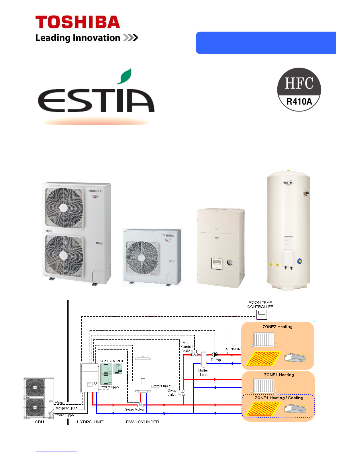
Quick Reference
Air to Water Heat Pump
Series 4
Page 2
1
Hydro Unit
HWS-
804H-**
HWS-
1104H-**
HWS-
1404H-**
HWS-
1104H8-**
HWS-
1404H8-**
HWS-
1604H8-**
HWS-
1104H8R-**
HWS-
1404H8R-**
HWS-
1604H8R-E
Back Up
Heater
HWS-804XWHM3-** P
- - - - - - - - ~, 3Kw
HWS-804XWHT6-** P
- - - - - - - - 3N, 6kW
HWS-804XWHT9-** P
- - - - - - - - 3N, 9kW
HWS-1404XWHM3-**
- P P P P P P P P ~, 3Kw
HWS-1404XWHT6-**
- P P P P P P P P 3N, 6kW
HWS-1404XWHT9-**
- P P P P P P P P 3N, 9kW
Outdoor Unit
Hydro Unit
HWS-1501
CSHM3-E
HWS-2101
CSHM3-E
HWS-3001
CSHM3-E
HWS-1501
CSHM3-UK
HWS-2101
CSHM3-UK
HWS-3001
CSHM3-UK
HWS-804XWHM3-**
HWS-804XWHT6-**
HWS-804XWHT9-**
HWS-1404XWHM3-**
HWS-1404XWHT6-**
HWS-1404XWHT9-**
Hot Water Cylinder
P
Estia System
Component Combinations
Outdoor unit
Hydro unit
Hot Water
Hot water
cylinder
Under floor heating
(Zone Control)
Radiator
Fan coil unit
(Heating or Cooling)
Heating or Cooling
Page 3

2
New Features for 4 Series ESTIA:
A-rated water circulating pump installed in hydro unit
Minimum target water temperature reduced to 7°C in cooling mode for improved compatibility with fan
coil units
Hydro unit pump ON / OFF cycling function – to momentarily operate water pump during long periods of
system OFF
Option to use an external cylinder thermostat, on locally supplied hot water cylinders, for domestic hot
water production
Improved control for second remote controller when used with under floor heating
Improved control for ESTIA / boiler connection
New expansion vessel for hydro unit
New compressor for single phase ESTIA outdoor units
Note:
Under floor heating components, fan coil units, radiators, valves and other installation materials must be
procured locally.
Notes on System Design
• The input water temperature to the hydro unit must be 50°C or less. This is especially important if the
hydro unit is used in conjunction with any other external heating source (auxiliary boiler, electric booster
heaters etc.)
Unit failure or water leaks may result if the return water temperature, to the hydro unit, exceeds 50°C
• The minimum flow rate for the circulating water in the heating/cooling circuit must meet the following
range:-
11, 14 and 16 kW: 17.5 L/minute or more
8 kW: 13 L/minute or more
If the flow rate becomes less than the flow rate specified above, the flow switch in the hydro unit is activated
to stop operation.
When thermostatic devices are used for temperature control a bypass valve must be fitted to the heating
circuit, to ensure the minimum water flow rate is maintained in the event of all thermostatic devices closing
at the same time
• Only use the water pump, built into the hydro unit, to circulate the water in the heating circuit
• The hydro unit back up heaters will operate to assist the heat pump capacity output during low ambient
conditions
• The hydro unit has been designed for indoor installations. Do not install outside where there is a risk of
low ambient conditions. This may cause the water in the pipe work to freeze
• Make the water circuit closed. Never use it as an open circuit.
• To prevent damage to the system the volume of the circulating water must be 20 litres or more. If total
volume of water amount is less than 20 litres, then the unit may not function fully due to the operation of
protective controls.
Page 4
3
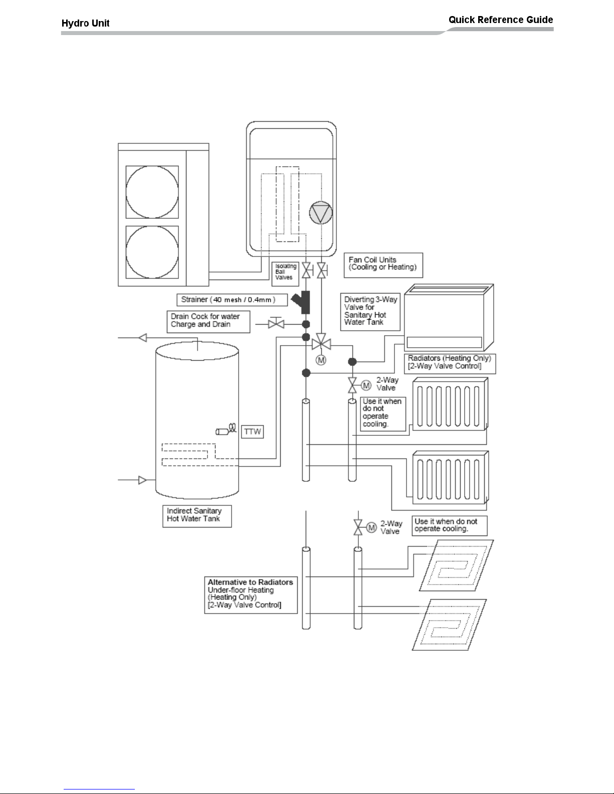
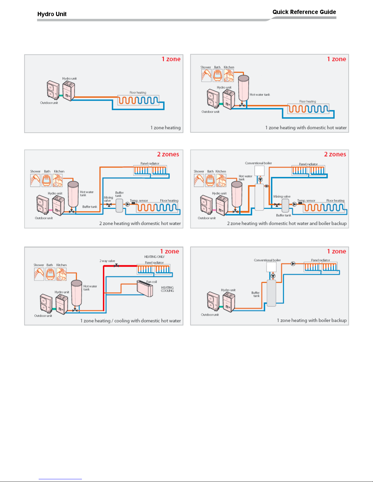
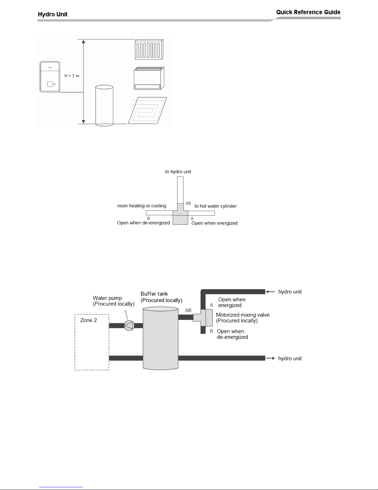
Installation Examples
Cooling and Heating with Domestic Hot Water
When both cooling and heating are used, install a 2-way valve (for cooling) to the pipe to the room
for heating only.
Page 5
4
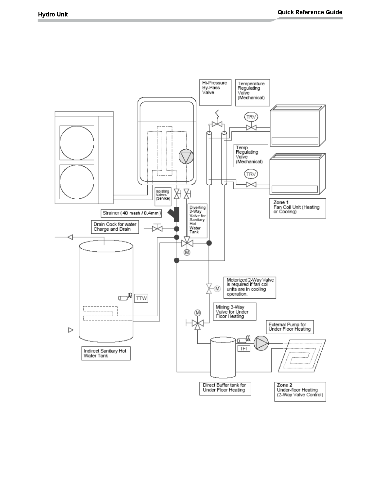
Installation Examples (cont.)
2-Zone Temperature Control with Domestic Hot Water
The following shows an example of the 2-zone temperature control.
A buffer tank and a water pump are required for the 2-zone temperature control. This example is
Heating only, if the Fan Coils are to be used for Cooling then a 2-Way valve must be fitted.
Page 6
5
Installation example of water circuit:-
(1) (2)
(3) (4)
(5) (6)
The water circuit for a system without a buffer tank [ (1) , (2) , (3) , (5) ] requires 17.5l/min
(804XWH = 13.0l/min) or more. This water flowing requires 5 or more branches of Floor heating or
Radiators etc.
Less than 5 branches may cause a flow deficiency. In this case, please provide a buffer tank and
secondary pumps, as shown in (4).
Please check how to install the boiler.
Page 7
6
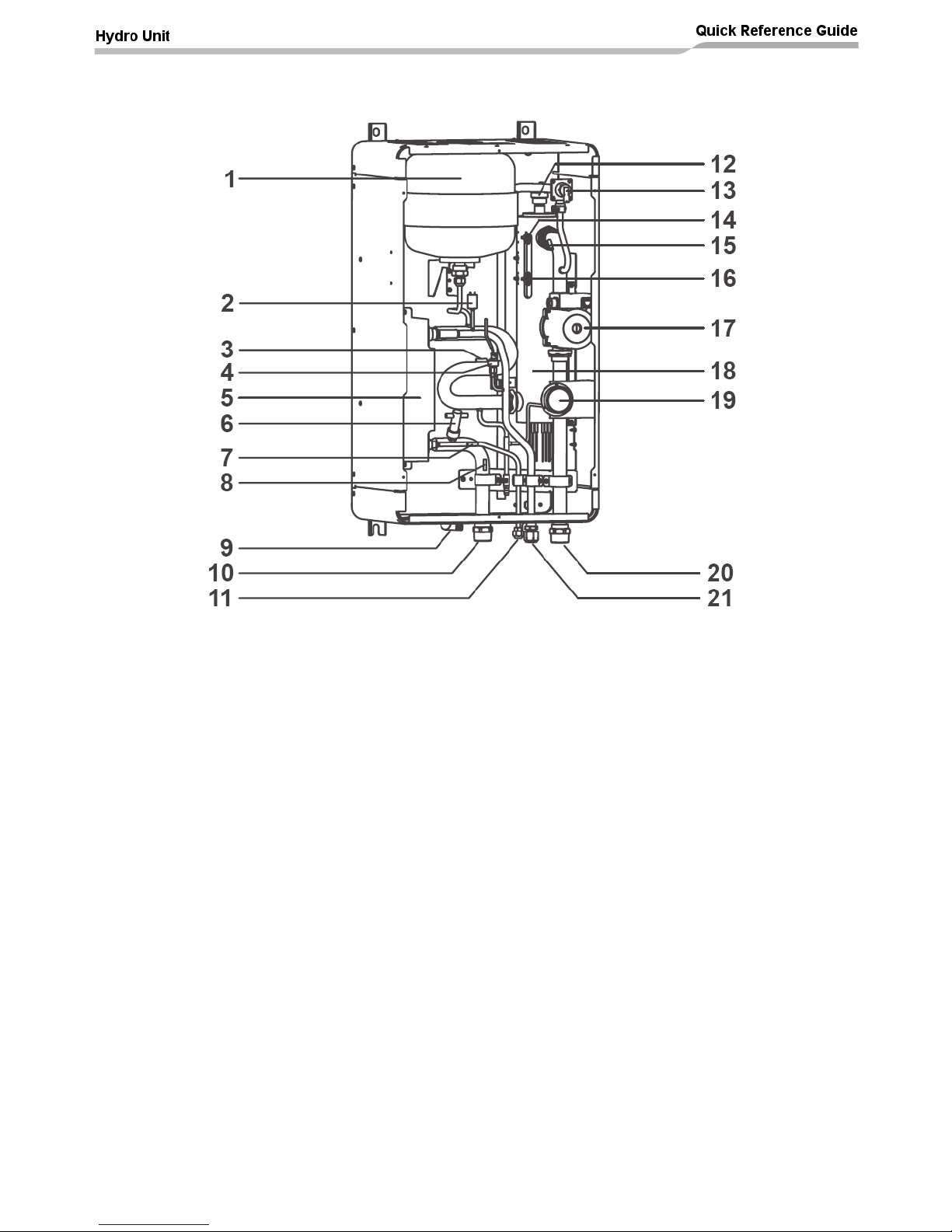
Hydro Unit – Exploded View
1. Expansion vessel
2. Hi Pressure switch (4.15 MPa)
3. Temperature sensor (for Heat pump outlet -TWO)
4. Pressure sensor
5. Heat exchanger
6. Flow switch (13.0 L/min 17.5 L/min)
7. Temperature sensor (for refrigerant -TC)
8. Temperature sensor (for water inlet -TWI)
9. Drain nipple
10. Water inlet connection
11. Refrigerant liquid connection
12. Air relief valve
13. Pressure relief valve (0.3 MPa (3 bar))
14. Thermal protector (auto)
15. Temperature sensor (for water outlet THO)
16. Thermal protector (Single operation)
17. A-rated water pump
18. Backup heater (3 kW, 3 kW x 2, 3 kW x 3)
19. Manometer
20. Water outlet connection
21. Refrigerant gas connection
Page 8
7
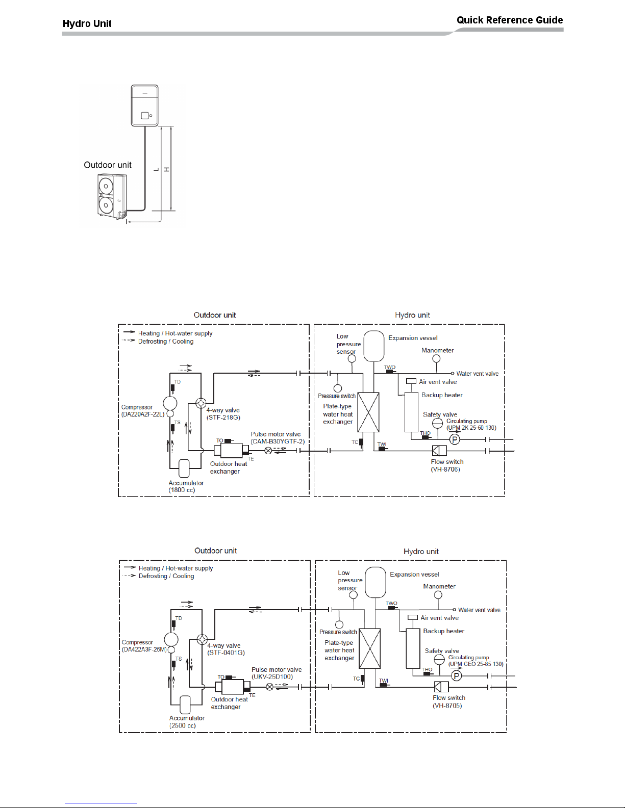
Refrigerant Pipe Lengths and Height
The length and height of the refrigeration pipe must be within the following values.
As long as the Hydro Unit is installed within these ranges, no additional refrigerant is required.
Minimum Pipe Length
HWS-804H-E : 5 m
HWS-1104H**-E : 5 m
HWS-1404H**-E : 5 m
HWS-1604H**-E: 5m
Maximum Pipe Length and Height
H: Max. ±30 m (above or below)
L: Max. 30 m
Note
The maximum pipe length cannot be increased by increasing the
refrigerant charge
The minimum pipe length cannot be decreased by reducing the
refrigerant charge
Refrigeration and Water Cycle Diagrams
Outdoor Unit: HWS-804H-E
Hydro Units: HWS-804XWH**-E
Outdoor Units: HWS-1104H**-E, HWS-1404H**-E
Hydro Units: HWS-1404XWH**-E
Page 9
8
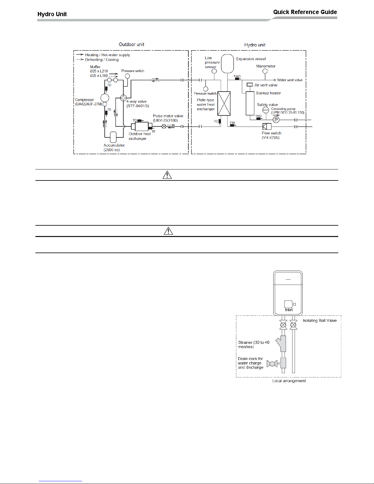
Outdoor Units: HWS-1104H8(R)-E, HWS-1404H8(R)-E, HWS-1604H8(R)-E
Hydro Units: HWS-1404XWH**-E
Water Piping
WARNING
• Ensure that the heating circuit, and all components of the heating circuit, are installed in accordance with
all National and local regulations
• The water pipes must not be installed where they are exposed to low ambient air temperatures. This is to
prevent the water freezing in the pipes
• Make sure that water pipes have sufficient pressure resistance
(The setting value of the pressure relief valve is 0.3 MPa).
CAUTION
• Do not use zinc plated water pipes. When steel pipes are used, insulate both ends of the pipes.
• The water to be used must meet the water quality standards specified in EN directive 98/83 EC.
Water Circuit
• Install a strainer with 30 to 40 meshes (procure locally) at the
water inlet of the Hydro Unit
• Install drain cocks (procure locally) for water charge and discharge
at the lower part of the Hydro Unit
• The ESTIA system can only be used on pressurised heating
circuits. If the system is used on gravity fed heating circuits then
system failure may occur
Page 10
9
Water Piping Limitations
Design the water pipe length within the QH characteristics
of the pump (flow-rate and pump head).
The maximum height difference for the water pipes is 7
metres.
Piping to hot water tank (option)
Water supplied to the hot water cylinder is branched by a motorized 3-way valve (procured locally).
Connect the hot water cylinder to port A (open when energized) of the valve.
Piping to 2-zone operation (option)
To perform 2-zone temperature control circulate water using another pump (procured locally) through a
motorized mixing valve (procured locally) and a buffer tank (procured locally).
Page 11
10
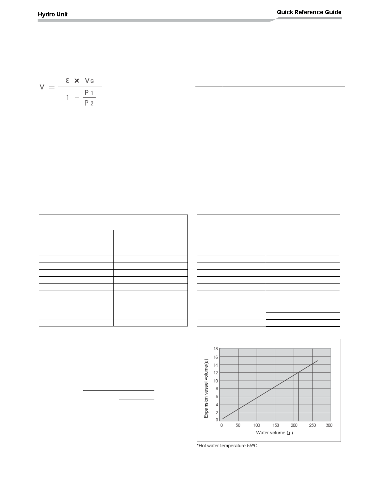
Checking water volume and initial pressure of expansion vessel
The expansion vessel of the Hydro Unit has a capacity of 12 litres.
The initial pressure of the expansion vessel is 0.1 MPa (1 bar).
The pressure of the safety valve is 0.3 MPa (3 bar).
Verify whether the capacity of the expansion vessel is sufficient using the following expression. If the
volume is insufficient, install an appropriate external expansion vessel.
V
Action
< 12 L
Internal Expansion Vessel Size OK
> 12 L
Internal Expansion Vessel Size too small.
Install appropriate external expansion vessel
V: Necessary total vessel capacity (L)
Ɛ: Water expansion coefficient at average hot water temperature
Vs: Total water volume in the closed system (Do not include Hot Water Cylinder)
P1: System pressure at tank setting position (Mpa_abs*).
(Pipe inner pressure during pump operation before heating device operates = water supply
pressure)
P2: Maximum pressure used during operation at tank setting position (MPa_abs*).
(= safety valve setting pressure)
* The absolute pressure value (abs.) is obtained by adding the atmospheric pressure (0.1 MPa (1 bar)) to
the gauge pressure.
Water temperature and expansion coefficient (Ɛ)
Water temperature and expansion coefficient (Ɛ)
Hot water temperature
(°C)
Expansion rate
(Ɛ)
Hot water temperature
(°C)
Expansion rate
(Ɛ)
0
0.0002
50
0.0121
4
0.0000
55
0.0145
5
0.0000
60
0.0171
10
0.0003
65
0.0198
15
0.0008
70
0.0229
20
0.0017
75
0.0258
25
0.0029
80
0.0292
30
0.0043
85
0.0324
35
0.0050
90
0.0961
40
0.0078
95
0.0967
45
0.0100
-
-
Example
Maximum Hot Water temperature: 55°C
Initial water charge: 0.2MPa
System volume: 200 L.
Calculate Vessel capacity (V):-
In this case V < 12 L therefore the internal expansion
vessel is sufficient, so there is no need to install an
external expansion vessel.
V =
0.0145
x
200
(0.2 + 0.1)
(0.3 + 0.1)
V =
11.6L
1
-
Page 12

11
Pump QH curves
HWS-804XWHM3-E, T6-E, T9-E
HWS-1404XWHM3-E, T6-E,T9-E
Page 13
12
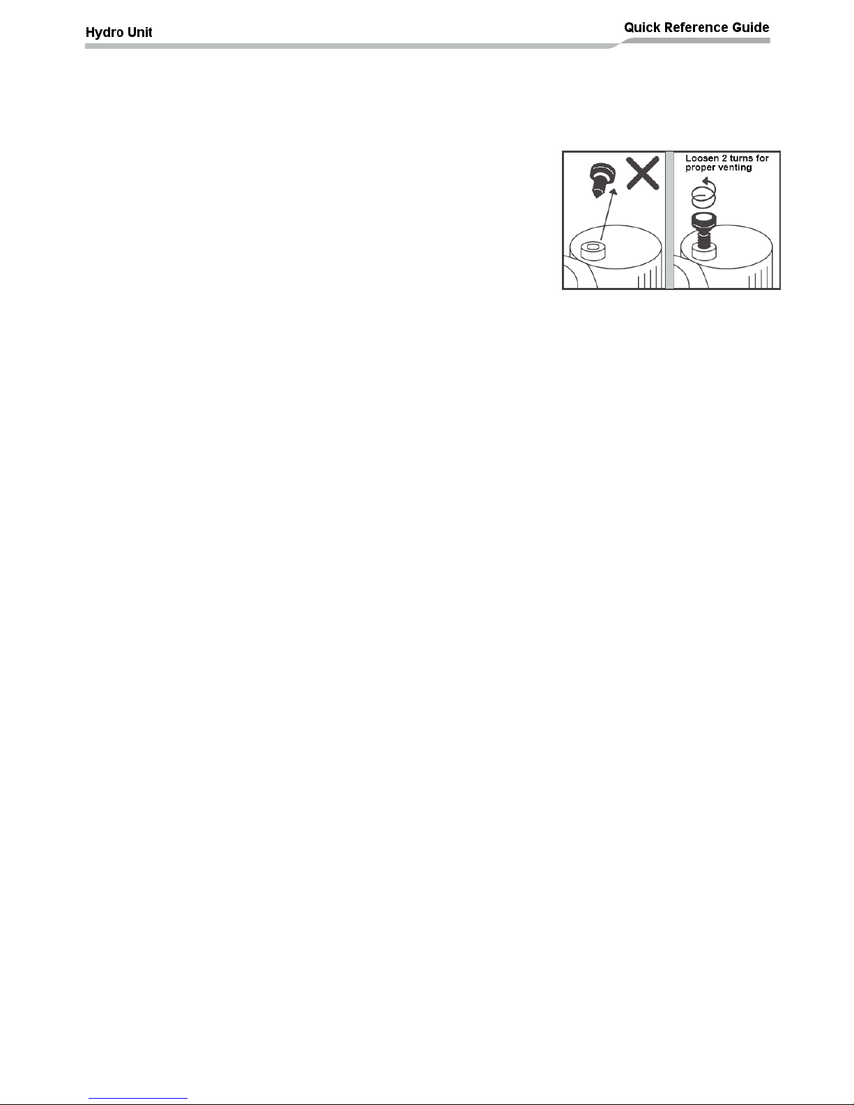
Water charging
Charge the water, in the heating circuit, until the pressure gauge shows 0.2 MPa (2 bar).
The hydraulic pressure may drop when the trial run begins. In this case, add water until the hydraulic
pressure returns to 0.2MPa (2 bar)
Air may enter the heating circuit if the hydraulic pressure is low.
Loosen the Air relief valve cap by two turns to release air (see diagram).
Ensure all air is removed from the system. If air remains in the system
then the system operation may STOP.
Note: Due to the design of the electrical back up heater it is not
recommended to add any corrosion inhibitors / additives to the
heating circuit.
Water quality
The water used must satisfy EN directive 98/83 EC.
Piping insulation
It is recommended that insulation is fitted to all pipes. To perform optional cooling operation, apply
insulation with a rating of 20t or more to all pipes.
Page 14
13
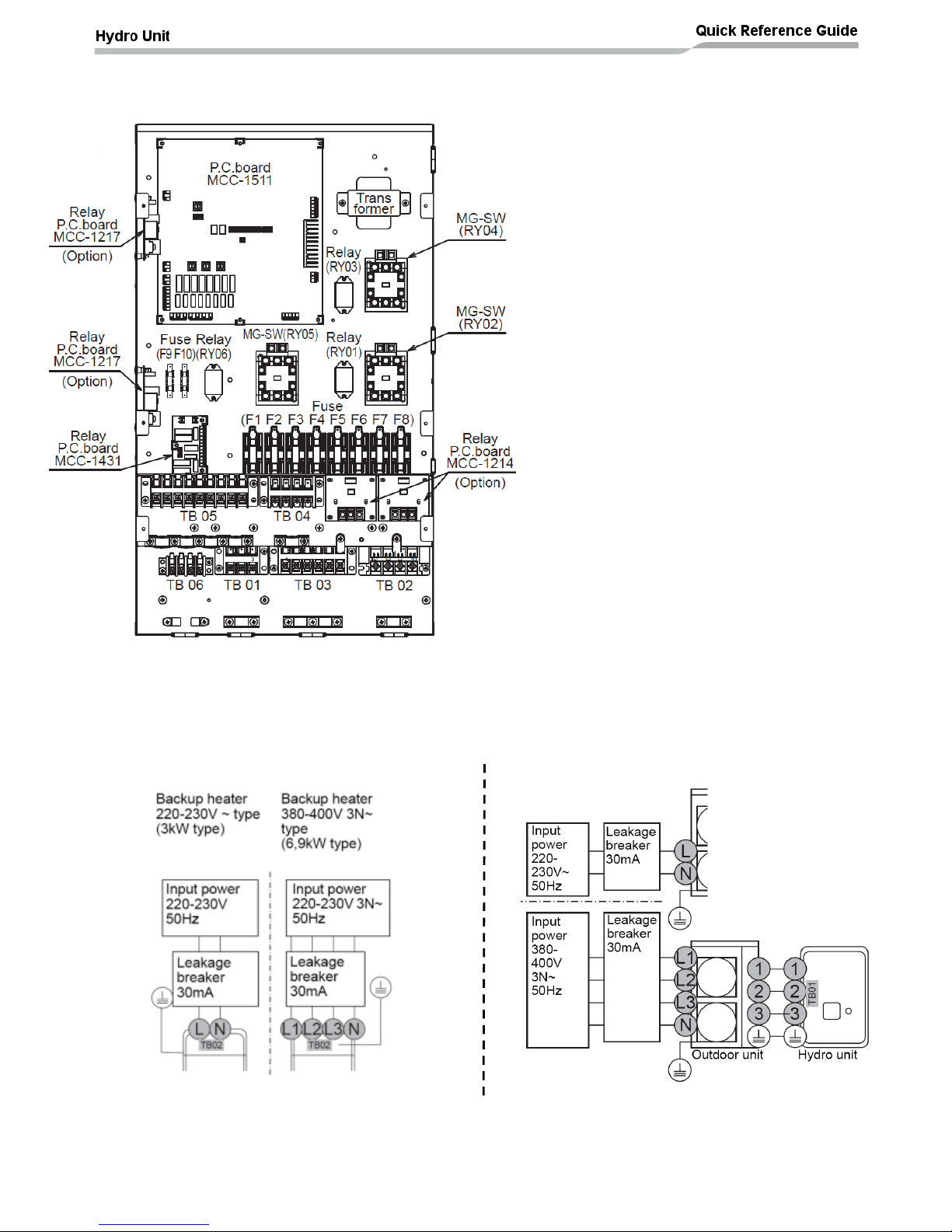
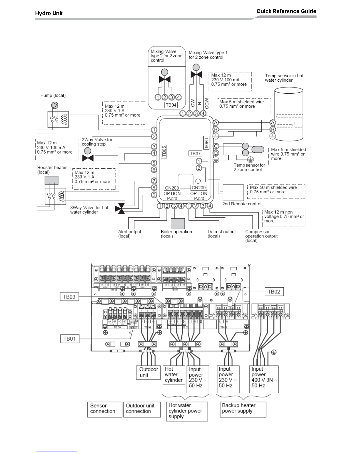
Electrical Connections
E Box layout
Power Lines Schematic
Fuses (AC250V T30A):
F1&F2: Hot water cylinder electric heater supply
F3&F4: Back up heater 1 (3kW)
F5&F6: Back up heater 2 (3kW)
F7&F8: Back up heater 3 (3kW)
Fuses (AC250V T3.15A)
F9&F10: A rated water pump
PCB’s:
MCC-1214: TCB-PCMO3E (optional input PCB)
MCC-1217: TCB-PCIN3E (optional output PCB)
MCC-1431: Relay PCB for control of second
water pump, 2 way valve and booster heater
outputs
MCC-1511: Main hydro unit control / interface
PCB
Contactors & Relays:
RY01: Interlock relay – flow switch / back up
heater circuit
RY02: Power contactor for back up heater supply
RY03: Control relay for back up heater s 2 & 3
operation
RY04: Power contactor for back up heater supply
RY05: Power contactor for hot water cylinder
electric heater supply
RY06: Control relay for mixing valve (2 zone)
operation
Page 15
14
Control Lines Schematic
Terminal Block Connections
Page 16
15
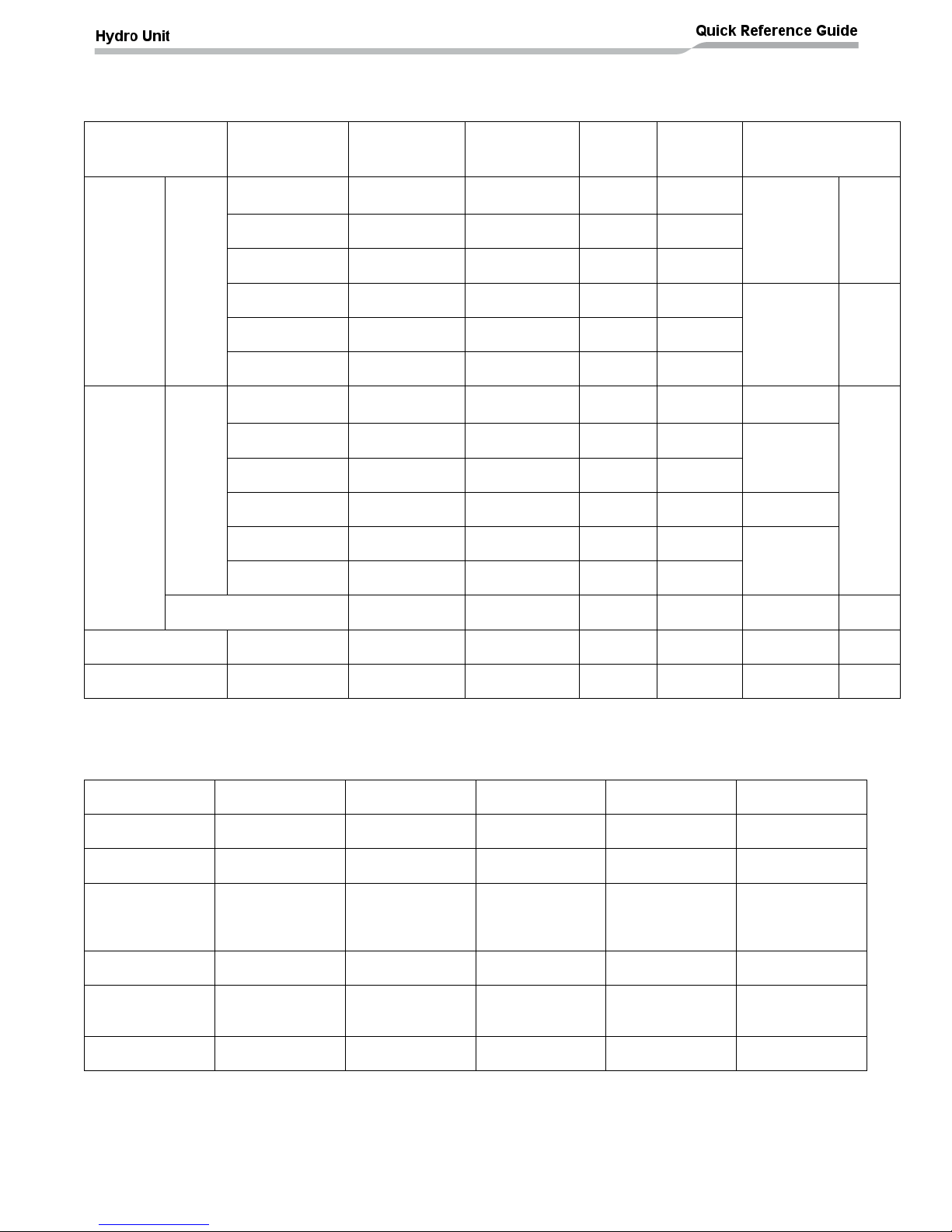
Electrical supply / cable specifications
Wiring specifications (power line)
Description
Model Name
HWS
Power Supply
Current
(Max)
Install
Fuse
Rating
Power
Cable
Connection
Destination
Outdoor
Unit
Power
Power
Input
1404H-E
220V-230V ~
50Hz
22.8A
25A
≥2.5mm
2
L, N
-
1104H-E
220V-230V ~
50Hz
22.8A
25A
≥2.5mm
2
804H-E
220V-230V ~
50Hz
19.2A
20A
≥2.5mm
2
1604H8(R)-E
380-400V 3N~
50Hz
14.6A
16A
≥2.5mm
2
L1, L2, L3,
N
-
1404H8(R)-E
380-400V 3N~
50Hz
14.6A
16A
≥2.5mm
2
1104H8(R)-E
380-400V 3N~
50Hz
14.6A
16A
≥2.5mm
2
Hydro
unit
electric
heater
power
Power
input
for
back
up
heater
1404XWHM3-E
220V-230V ~
50Hz
13A
16A
≥1.5mm
2
L, N
TB02
1404XWHT6-E
380-400V 3N~
50Hz
13A (13Ax2P)
16A
≥1.5mm
2
L1, L2, L3,
N
1404XWHT9-E
380-400V 3N~
50Hz
13A (13Ax3P)
16A
≥1.5mm
2
804XWHM3-E
220V-230V ~
50Hz
13A
16A
≥1.5mm
2
L, N
804XWHT6-E
380-400V 3N~
50Hz
13A (13Ax2P)
16A
≥1.5mm
2
L1, L2, L3,
N
804XWHT9-E
380-400V 3N~
50Hz
13A (13Ax3P)
16A
≥1.5mm
2
Power input for DHW
cylinder heater
220V-230V ~
50Hz
12A
16A
≥1.5mm
2
L, N
TB03
Outdoor – hydro
unit connection
- - -
-
≥1.5mm
2
1, 2, 3
TB01
Hydro unit to DHW
cylinder
- - -
-
≥1.5mm
2
1, 2
TB03
Wiring specification (control line)
Description
Line Spec
Current (Max)
Length (Max)
Cable Diameter
Connection
Destination
3 way diverting
valve
2 or 3 wire
100mA
12m
1.0mm
2
7, 8, 9 (TB05)
2 way valve
(cooling)
2 wire
100mA
12m
1.0mm
2
3, 4 (TB05)
3 way mixing
valve (2 zone)
3 wire
100mA
12m
1.0mm
2
1, 2, 3
or
2, 3, 4
(TB04)
2 zone thermo
sensor (TFI)
2 wire
100mA
5m
1.0mm
2
C, D (TB06)
HW cylinder
thermo sensor
(TTW)
2 wire +GND
(screened cable)
100mA
5m
1.0mm
2
A, B (TB06)
2nd remote
controller
2 wire
50mA
50m
≥ 0.5mm
2
1, 2 (TB07)
Page 17
16
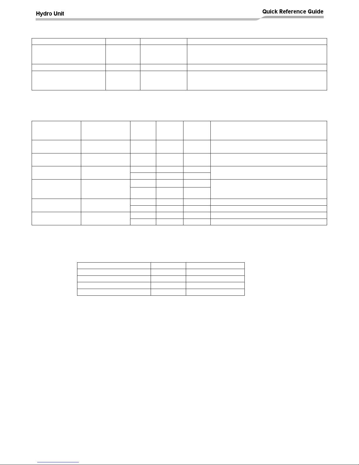
Control parts specifications
Component
Power
Current (Max)
Specification
3 way diverting valve
AC 230V
100mA
Default: 2 wire spring return valve or 3 wire SPST
valve
Option: 3 wire SPDT valve (set DPSW13_1 to ON)
2 way valve (cooling )
AC 230V
100mA
2 wire spring return valve (normally OPEN)
3 way mixing valve (2 zone
control)
AC 230V
100mA
Default drive time = 60 seconds to 90°
3 wire SPST or SPDT with drive times to 90° between
30 and 240 seconds
Output line specifications
Description
Output
Current
(Max)
Voltage
(Max)
Cable
Length
(Max)
Comments
External water
pump (P2)
AC230V
1A - 12m
External booster
heater
AC230V
1A - 12m
Output enabled when outdoor air
temperature is ≤ -20°C
Alarm output
No volt contacts
0.5A
AC230V
12m
1A
DC24V
12m
Boiler output
No volt contacts
0.5A
AC230V
12m
Output enabled when outdoor air
temperature is ≤ -10°C (output trigger
temperature can be changed using FC23)
1A
DC24V
12m
Defrost output
No volt contacts
0.5A
AC230V
12m 1A
DC24V
12m
Compressor ON
output
No volt contacts
0.5A
AC230V
12m 1A
DC24V
12m
Input line specifications
Description
Input
Cable Length (Max)
External stop control
No voltage
12m
Cylinder thermostat
No voltage
12m
Room thermostat (cooling)
No voltage
12m
Room thermostat (heating)
No voltage
12m
Page 18
17
CAUTION
Earthing arrangements
The Hydro Unit and related equipment must be earthed in accordance with your local and national electrical
regulations.
It is essential that the equipment is earthed to prevent the electric shock and damage to the equipment.
Electrical connection to hydro unit
• Remove the front cover and the electrical box cover from the Hydro Unit.
• The Hydro Unit power cable, for the electrical back up heaters, must be sized in accordance with the
Wiring Specifications table shown on page 15
• Connect the Hydro Unit power cable, for the electrical back up heaters, to Terminal 02 as shown below.
Single Phase Units: Live conductor – Terminal L1
Neutral conductor – Terminal L2
Earth conductor – Earth terminal
Three Phase Units: Phase 1 conductor – Terminal L1
Phase 2 conductor – Terminal L2
Phase 3 conductor – Terminal L3
Neutral conductor – Terminal N
Earth conductor – Earth
• Ensure the Hydro Unit power cable, for the electrical back up heaters, is secured using the cable clamp
fitted in the electrical box.
• Ensure the Hydro Unit power cable connection (for the electrical back up heaters) terminals are tight.
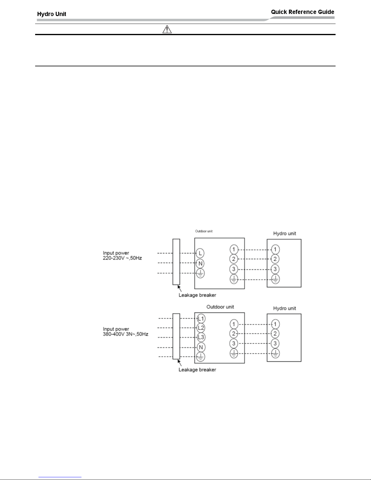
Outdoor unit to hydro unit electrical connection
• Ensure electrical circuits are isolated before commencing work.
• The Outdoor Unit to Hydro Unit interconnecting cable must be sized in accordance with the “Wiring
Specification” table shown on page 15
• Connect the Outdoor Unit to Hydro Unit interconnecting cable as shown in the diagram above.
• Ensure the Outdoor Unit to Hydro Unit interconnecting cable is secured using the cable clamp fitted in the
electrical box.
• Ensure the Outdoor Unit to Hydro Unit interconnecting cable connection terminals are tight.
HWS-804H-E
HWS-1104H-E
HWS-1404H-E
HWS-1104H8-E, H8R-E
HWS-1404H8-E, H8R-E
HWS-1604H8-E, H8R-E
Page 19
18
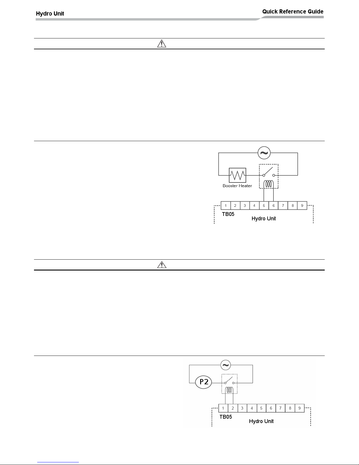
Electrical connection for external booster heater
CAUTION
• The maximum current available from the booster heater output is 1 A. Do not connect the booster
heater directly to Terminal Block 05 on the Hydro Unit. A separate contactor, supplied locally, must
be used to supply the booster heater.
• The booster heater can be installed only for room heating and cannot be used for hot water supply.
• Install the booster heater downstream of the 3-way valve on the heating circuit side of the installation
• The booster heater is an external heater, supplied locally, used to assist the Hydro Unit during low
ambient conditions.
• The AC230 V 1 A output from the Hydro Unit must only be used to energize an external contactor
(supplied locally).
• The output from the Hydro Unit is only enabled when either the outdoor air temperature to be lower than -
20°C.
• Ensure the external booster heater is installed and set up in accordance with all Local, National and
International regulations.
• Connect the external booster heater to the Hydro Unit
according to the diagram shown opposite:-
• The contactor will energize in the event of low ambient
conditions.
• A separate dedicated electrical supply must be used for the
external booster heater. This must be connected through the
contacts on the field supplied contactor.
Electrical connection for external additional pumps
CAUTION
• The maximum current available from the additional pump output is 1 A. Do not connect the
additional pump directly to Terminal Block 05 on the Hydro Unit. A separate contactor, supplied
locally, must be used to supply the additional pump.
• The Hydro Unit has the facility to connect an additional circulating pump, if required, into the heating or
cooling system.
• Install the pump so that its motive power does not affect the internal pump.
• The AC230 V 1 A output from the Hydro Unit must only be used to energize an external contactor
(supplied locally).
• The output for the pump is synchronized with the operation of the main circulating pump (P1) inside the
Hydro Unit.
• Ensure the pump is installed and set up in accordance with all Local, National and International
regulations.
• Connect the additional pump (P2) as shown in the
diagram opposite:-
• The contactor will energize synchronously with
operation of the main circulation pump (P1).
• A separate dedicated electrical supply must be
used for the pump. This must be connected through
the contacts on the field supplied contactor.
Page 20
19
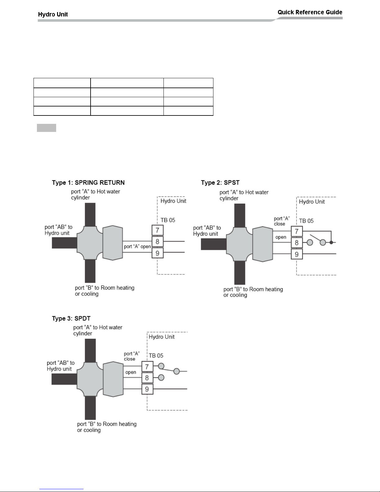
3-way valve (diverter) connection
Required Valve Specification:
Electrical Specification: 230 V; 50 Hz; <100 mA
Valve Diameters: Port A, Port B: Ø 1 1/4"
Return Mechanism: 3 types of 3-way valve (diverter) can be used.
Set the 3-way valve in use with the DIP switch SW13-1 on the Hydro Unit board.
Diverter Valve
Description
DPSW13-1
Type 1
2-wire spring return
OFF
Type 2
3-wire SPST
OFF
Type 3
3-wire SPDT
ON
NOTE
Continuous operation of the valve motor at the fully open position is not recommended.
• The 3-way diverter valve is used to select either domestic hot water or zone1 / zone2 space heating
• Connect the 3-way diverter valve in accordance with the diagram below:-
Page 21

20
3-way mixing valve connection
Required Actuator Specification
Electrical Specification:230 V; 50 Hz; <100 mA
The 3-way mixing valve is used to achieve the temperature differential needed in a 2-zone heating system.
• Connect the 3-way mixing valve in accordance with the diagrams below:-
Hot water cylinder connection (optional)
• Please refer to “Electrical supply/cable specifications” for fuse/cable size and for connection
details.
Electrical Connection (Hot Water Cylinder Electric Heater)
• The electric heater, incorporated in the hot water cylinder, requires a separate supply to the Hydro Unit.
• Connect the hot water cylinder heater electrical supply in accordance with shown below:
Live conductor: Terminal L on Terminal Block 03
Neutral conductor: Terminal N on Terminal Block 03
Earth Conductor: Earth terminal on Terminal Block 03
• Connect the hot water cylinder heater to the Hydro Unit as shown below:
Live conductor to hot water cylinder: Terminal 1 on Terminal Block 03
Neutral conductor to hot water cylinder: Terminal 2 on Terminal Block 03
Earth conductor to hot water cylinder: Earth terminal on Terminal Block 03
Please ensure that the interconnecting cable, between the Hydro Unit and the hot water cylinder, is
connected to earth at both ends of the cable using the shield wire or the earth conductor of the
interconnecting cable.
Electrical Connection (Hot Water Cylinder temperature Sensor)
• Connect the hot water cylinder temperature sensor as shown below to terminals A & B on Terminal Block
06 in the Hydro Unit.
Page 22

21
Second Remote Controller Installation (optional)
It is possible to connect a second remote controller to the ESTIA system.
The remote controller should be installed between 1m to 1.5m above floor level so that the remote
controller measures the average room temperature
The remote controller must not be installed in areas of:
Direct sunlight or areas exposed to outside air influences
Poor ventilation (near windows or other openings)
External heat sources (above radiators etc.)
Freezing or refrigerated areas
The remote controller must be installed in a vertical position
Second Remote Controller Connection
The remote controller can be set as either the header or second remote controller and to measure either
water temperature or room air temperature.
Remote Controller DIPS Switches - Setting
Set one of the remote controllers as the header remote controller (remote controller of hydro unit
is preset as the header remote controller (DPSW1 = OFF)
Set the DPSW’s on the other remote controller PC boards to “second” (optional remote controller
is preset as “second” – DPSW1 = ON)
For room air temperature control
set function code 40 (on the hydro unit) to “1”
Set DPSW2 to ON only on the remote controller used for room temperature measurement
Either the header or the second remote controller can be set for room temperature
measurement. Please do not set DPSW2 to ON on both the header and follower remote
controllers
2 core shielded cable – 0.5mm2
or more.
Maximum cable length – 50m
Second remote controller
connections. Terminals A
and B are non polar.
Terminal block TB07, for
remote controller
connection, to hydro unit.
Page 23

22
Input / Output Option PCB’s – Installation
Output Options:
It is possible to connect to outputs, using the TCB-PCIN3E option PCB’s, on the ESTIA hydro unit for the
following functions:
Alarm output
Boiler output
Defrost
Compressor ON
System alarm & boiler outputs:
Alarm output (L1): Output ON when the system is in alarm/fault conditions. The output is
available through a volt free contact on the TCB-PCIN3E option PCB.
Boiler control output (L2): Output ON when outdoor ambient temperature is less than or equal
to the temperature set in FC23. The output is available through a volt free contact on the TCBPCIN3E option PCB.
Defrost & compressor ON outputs:
Defrost output (L1): Output ON when the system / outdoor unit is under defrost control. The
output is available through a volt free contact on the TCB-PCIN3E option PCB.
Compressor ON output (L2): Output ON when the outdoor unit compressor is operating. The
output is available through a volt free contact on the TCB-PCIN3E option PCB.
Page 24

23
Volt free contact specification: The volt free contact specification, for the outputs detailed
above, is shown below:
AC230V: 0.5A (maximum)
DC24V: 1.0A (maximum)
Input Options:
It is possible to connect inputs, using the TCB-PCMO3E option PCB’s, on the ESTIA hydro unit for the
following functions:
External room thermostat
External hot water cylinder thermostat
External STOP
External room thermostat:
The diagram above shows the thermostat connections for heating and cooling mode. The
thermostat must be manually switched between heating and cooling (the operating mode, on the
ESTIA remote controller must also be changed manually). The system cannot change between
heating and cooling modes automatically.
For cooling operation connect the cooling contact, on the thermostat, between terminals 2 (COOL) &
3 (COM) on the option PCB (as shown above).
For heating operation connect the heating contact, on the thermostat, between terminals 1 (HEAT) &
3 (COM) on the option PCB (as shown above).
Control Logic:
Option PCB
Terminal Nos.
Cooling Operation
Heating Operation
ON
OFF
ON
OFF
2 ~ 3
OPEN
CLOSED
-
-
1 ~ 3
-
-
CLOSED
OPEN
Page 25

24
External hot water cylinder thermostat:
Connect the external hot water cylinder thermostat (S1 in the diagram below) to terminals 2 (COOL) and
3 (COM) on the option PCB.
When the hot water cylinder thermostat contact, S1, is CLOSED then there is a hot water demand and the
system will produce hot water (if all DPSW’s and function codes are set correctly)
External system STOP:
Connect the external STOP signal / contact (S2 in the diagram above) to terminals 1 (HEAT) and 3 (COM)
on the option PCB.
It is possible to set the operating logic of contact S2 (normally OPEN contact, normally CLOSED contact or
pulse input) using function code FC52 and the operating mode of the system, on restart, using FC61 (see
function code list on page 31 for options).
The external stop option can also be used for TEMPO control where an external signal, from the customers
electricity measuring meter, is applied to the option PCB (contact S2 connections). TEMPO control can be
used as part of the price contract provided by French electric power company EDF. The TEMPO control
options are set using FC61.
Page 26

25
Start up and Configuration
Setting DIP Switches on the Board in the Hydro Unit
• Detach the front cover and the electric parts box cover of the
Hydro Unit.
• Set the DIP switches on the main board.
Switch
No.
Bit
No.
Description
Factory
Position
02
1
Determines the position of the auxiliary boiler in the system installation:
OFF = Boiler positioned after the 3 way valve
ON = Boiler installed before the 3 way valve
OFF
2
Not Used
-
3
Used when an external cylinder thermostat is connected:
OFF = external cylinder thermostat not connected
ON = external room thermostat connected
OFF
4
Used when an external room thermostat is connected:
OFF = external room thermostat not connected
ON = External room thermostat connected
OFF
10
1
Synchronises pump P1 with HP during hot water production:
OFF = Pump P1 synchronised with HP during hot water mode when electric cylinder heater is
energised
ON = Pump P1 continuous operation
OFF
2
Pump P1 control using TO control (heating mode only):
OFF = Pump P1 continuous operation
ON = Pump P1 OFF when TO > 20°C (temperature can be changed using FC9E)
OFF
3
Synchronises pump P2 with pump P1:
OFF = Pump P2 continuous operation (P2 OFF when remote controller switched OFF)
ON = Pump P2 synchronised with pump P1
OFF
4
Pump P1 ON/OFF cycling (during long periods of system OFF):
OFF = Pump P1 normal operation
ON = Pump P1 ON for 10 minutes duration (if system has been stopped for 72 hours)
OFF
11
1
Used to enable the hydro unit back up heaters:
OFF = Back up heater control enabled
ON = Back up heater control disabled
OFF
2
Used to enable the hot water cylinder electric heater:
OFF = Hot water cylinder heater control enabled
ON = Hot water cylinder heater control disabled
OFF
3
Used to enable the external booster heater output control:
OFF = External booster heater control enabled (TO must be ≤ -20°C)
ON = External booster heater control disabled
OFF
4
Not Used
-
12
1
Used to determine hot water cylinder connection to the system:
OFF = Hot water cylinder connected to the system
ON = Hot water cylinder not connected to the system
OFF
2
Used to enable Zone 1 operation:
OFF = Zone 1 control enabled
ON = Zone 1 control disabled
OFF
3
Used to enable Zone 2 operation:
OFF = Zone 2 control disabled
ON = Zone 2 control enabled
OFF
4
Not Used
-
13
1
Used to determine type of 3 way diverting valve connected to system:
OFF = 2 wire spring return or 3 wire SPST valve connected
ON = 3 wire SPDT valve connected
OFF
2
Used to enable the external boiler output control (used with FC23):
OFF = External boiler output control disabled
ON = External boiler output control enabled
OFF
3
Used to enable system auto restart after system power failure:
OFF = Auto restart control enabled
ON = Auto restart control disabled
OFF
4
Not Used
-
Page 27

26
Hydro Unit Remote Control
Buttons
1. TEMP. button:
Changes the set temperature for
each operation mode (ZONE1 /
ZONE2 / HOT WATER) by 1°C
step.
10. NIGHT button:
Controls the night set back
operation.
2. SCHEDULE
button:
Sets the current time and
scheduled weekly operation.
11. AUTO TEMP.
button:
Switches setting temperature
automatically according to outside
temperature. (Pressing this button
long changes the mode to data
setting mode).
3. TIME button:
Changes time for current time
setting and scheduled weekly
operation setting with ▼ and ▲
buttons.
12. OPERATE
MODE button:
Selects ZONE1 / ZONE2 operation
mode (heating or cooling).
4. SET button:
Determines the entered current
time setting and scheduled weekly
operation setting.
13. ZONE1, 2
button:
Turns on/off the zone (floor
heating/radiator/FCU) operation.
5. CL button:
Clears settings for the current time
and scheduled weekly operation.
14. ANTI BACTERIA
button:
Regularly increases the hot water
temperature in the tank for
sterilization. (Pressing this button
long changes the mode to data
setting mode).
6. DAY button:
Sets days of the week for current
time setting and scheduled weekly
operation setting.
15. HOT WATER
BOOST button:
Boosts boiling when high tapping
temperature is required temporarily.
7. STEP button:
Specifies switching STEP number
in a day for weekly schedule.
16. HOT WATER
button:
Turns on/off hot water operation.
8. TEST button:
Used for test run or service.
17. SELECT button:
Selects an operation mode when
changing the set temperature of
each operation mode.
9. FROST
PROTECTION
button:
Controls minimum operation for
unused period (going out,
absence,etc.) for anti freezing.
NOTE
Some functions are not provided depending on the system specification in use.
Page 28

27
Display Explanation
18: ZONE1, ZONE2
20: HOT WATER
Display
Description
Display
Description
Lights when floor heater or radiator
is connected (when the system has
floor heater or radiator).
Lights when hot water supply system is
connected (when the system has hot
water supply).
ZONE1 selected for Temperature
to be changed.
Lights when system configured to
have 2 zones.
ZONE2 selected for Temperature
to be changed.
HOT WATER selected for Temperature
to be changed.
Lights during heating or cooling
operation using the heat pump.
Lights when hot water supply operation
is performed by heat pump.
Lights when the internal heater is
energized during heating
operation.
Lights when the internal heater is
energized during hot water supply
operation.
Lights when heating is selected.
Lights during hot water supply operation.
Lights when cooling is selected.
Lights while hot water boost is activated.
Lights when the FROST
PROTECTION button is pressed
and goes out when the button is
pressed again.
Lights when the ANTI BACTERIA button
is pressed and goes out when the button
is pressed again.
Lights when Auto operation is
selected.
Lights when unit enters the data set
mode.
Displays heating/cooling set
temperature. (Heating: 20 to 55°C,
factory setting: Auto, cooling: 7 to
25°C) Goes out when Auto
operation is selected.
Displays hot water set temperature.
(40 to 75°C, factory setting: 65°C)
°C
Lights when the set temperature or
sensor's water temperature is
displayed with the 7-segment
indicator.
°C
Lights when the set temperature or
sensor's water temperature is displayed
with the 7-segment indicator.
Page 29

28
Display Explanation (cont.)
19: TIMER
21: CONTROL
Display
Description
Display
Description
Clock: Displays the current time
(AM or PM).
Lights while internal pump (P1) or
external pump (P2) is driven.
Displays days of the week (Sunday
to Saturday).
Lights during backup operation only by
the heater.
Lights when the NIGHT button is
pressed and goes out when the
button is pressed again.
Lights when the unit enters the data set
mode and goes out when the unit exits
the data set mode.
Lights when night time quiet
operation is set.
Lights when the unit enters the service
mode and goes out when the unit exits
the service mode.
Indicates scheduled operation 1
status (including setting time).
Lights when an error occurs and goes
out when the error is cleared.
Displays the scheduled operation
step when the scheduled operation
STEP1-5 program is set.
Lights for two seconds when settings are
completed.
Lights during time setting and
scheduled operation setting.
Lights for two seconds when settings
failed.
Remote Controller – Schedule Timer
It is possible to set up timer control schedules on the ESTIA remote controller (when two remote controllers
are fitted to the ESTIA system the schedule timer is only available from the HEADER remote controller).
A maximum of eight control STEPS can be programmed / scheduled, into the ESTIA remote controller, for
each day of the week.
Using the schedule timer function (see page 42 for example):
Accessing the schedule timer function:
Press the SCHEDULE button for 4 second or more to enter the schedule timer setting
mode. The remote controller will show the following display:
Specifying the day for the schedule timer:
Press the Day button to move the ▼symbol, displayed above the days of the week on the remote
controller, to the day when the scheduled timer id to take place. Each press of the DAY button
moves the ▼symbol to the next displayed day. When the ▼symbol is above the required day, press
the SET button to confirm the day to be set
Specifying the control STEP number:
Press the STEP button to specify the control STEP to be set. The STEP selection increments by 1
STEP for each press of the STEP button from STEP 1 to STEP 8.
Steps “C” and “L” are also available by continuing to press the STEP button when the remote
controller display shows STEP 8.
Page 30

29
If “C” is selected then the control details, already set for the specified day, are copied. These details
can be copied to other days of the scheduled timer
If “L” is selected then all of the control details, set for the specified day, are deleted
Specifying the Step ON/OFF time, operation mode & set temperature:
ON/OFF Time: Use the TIME ▲ ▼ buttons to set the required ON/OFF time for the specified control
step
Operating Mode: To select or deselect the hot water function press the HOT WATER button on the
remote controller
To select or deselect either space heating function press the Zone1, 2 button on the remote
controller
When the function is selected to turn ON (at the specified time) then a numerical temperature is
displayed in the relevant window on the remote controller. When the function is selected to Turn
OFF (at the specified time) then the remote controller will display - - - -
To select either heating or cooling press the OPERATE MODE button on the remote controller.
When heating is selected then will be displayed on the remote controller. If cooling mode is
selected then will be displayed.
Set Point Temperature: Press the SELECT button, on the remote controller to select either space
Zone 1, Zone 2 or HOT WATER. Press the TEMPERATURE ▲ ▼buttons to set the required
temperature
When the ON/OFF time, operating mode and set point temperature have been entered into the
schedule timer press the SET button to confirm the settings
Leaving the schedule timer function:
When the scheduled timer function has been set for the required days press the SCHEDULE button
to end the schedule setting function. The remote controller display will return to the main display
screen and the icon, on the remote controller display, will flash. Press the SET button within 5
seconds of the icon flashing – the icon changes to lit and is continuously displayed. The timer
schedule is now in operation
How to copy a program
When specifying the STEP number (see details above) select “C” and press the SET button. This
copies all of the previously set data for that day.
Press the DAY button to move the ▼ above the new schedule timer day. Press the SET button to
copy the required data into the new day.
Repeat this process for all days required
Page 31

30
Function Code Access
Set function codes for various operation modes, input using the remote controller.
There are 2 types of settings:-
1) Hydro Unit function code setting.
2) Remote controller function code setting.
Setting procedure for Hydro Unit function code
1. Press and hold + + buttons for four
seconds or more to enter the hydro unit function code setting mode.
2. Set the function code number with the TEMP. buttons
(CODE No.: 01 to B2).
3. Set data with the TIME buttons .
4. Press to confirm the settings.
5. Note that the Clear button is enabled only before the SET
button is pressed and the function code is changed.
6. Press to exit the settings menu.
Setting procedure for Remote Controller function code
1. Press and hold + + TEMP. buttons for four seconds
or more to enter the remote controller function code setting mode.
2. Set the function code number with the TEMP. buttons
(CODE No.: 01 to 13).
3. Set data with the TIME buttons .
4. Press to determine the settings.
5. Note that the Clear button is enabled only before the SET
button is pressed and the function code is changed.
6. Press to exit the settings menu.
Page 32

31
Function Code Setting
Function Code Setting
Function Code
Range
Default
Setting Address
Hydro
Unit
Remote
Controller
Setting Temperature
Range
Heating Upper Limit - Zone 1
1A
-
37~55°C
55
Heating Lower Limit - Zone 1
1B
-
20~37°C
20
Heating Upper Limit - Zone 2
1C
-
37~55°C
55
Heating Lower Limit - Zone 2
1D
-
20~37°C
20
Cooling - Upper Limit
18
-
18~30°C
25
Cooling - Lower Limit
19
-
7~20°C
7
Hot Water - Upper limit
1E
-
60~80°C
75
Hot Water - Lower limit
1F
-
40~60°C
40
Hot Water Operation
Heat Pump Start Temperature
20
-
20~45°C
38
Heat Pump Stop Temperature
21
-
40~50°C
45
Hot Water Temperature
Compensation
Temperature Compensation Outside Air
Temperature (°C)
24
-
-20~10°C
0
Compensation Temperature (K)
25 - 0~15K
3
Hot Water Boost
Operation Time (x10 min)
08 - 3~18
6
Setting Temperature (°C)
09
-
40~80°C
75
Anti Bacteria
Setting Temperature (°C)
0A
-
65~80°C
75
Start Cycle (Day)
-
0D
1~10
7
Start Time (Hour)
-
0C
0~23
22
Operation Time (min)
0B - 0~60
30
System Priority Setting
Hot water v heating – switching temperature (°C)
22
-
-20~20°C
0
External boiler – output ON temperature (°C)
23
-
-20~20°C
-10
Hot water v cooling priority selection:
0 = Cooling priority. Hot water produced by
electric cylinder heater
1 = Hot water priority. Hot water produced by HP
0F - 0~1
0
Heating Auto Curve
Settings
Outside Temperature T1 (°C)
29
-
-15~0°C
-10
Outside Temperature T2 (°C)
- - 0
0
Outside Temperature T3 (°C)
2B
-
0~15°C
10
Setting Temperature A @ OAT -20°C (°C)
2C
-
20~55°C
40
Setting Temperature B @ OAT T1 (°C)
2D
-
20~55°C
35
Setting Temperature C @ OAT T2 (°C)
2E
-
20~55°C
30
Setting Temperature D @ OAT T3 (°C)
2F
-
20~55°C
25
Setting Temperature E @ OAT 20°C (°C)
30
-
20~55°C
20
Ratio Of Zone 2 In Zone 1 Auto Mode (%)
31
-
0~100%
80
Auto Curve - Temperature Shift (K)
27 - -5~5K
0
Frost Protection
Function 0=Invalid; 1=Valid
3A - 0~1
1
Frost Protection Setting Temperature (°C)
3B
-
10~20°C
15
Frost Protection – Schedule End Day
-
12
0~20
0
Frost Protection – Schedule End Time
-
13
0~23
0
Back Up Heater
Control
Downtime Back Up Heater 0=5min;
1=10min;2=15min;3=20min
33 - 0~3
1
Uptime Back Up Heater 0=10min; 1=20min;
2=30min; 3=40min
34 - 0~3
0
Hot Water Cylinder
Heater Control
Determines the time between HP operation and
cylinder heater ON time
0 = 30 min, 1 = 60 min, 2 = 90 min, 3 = 120 min
73 - 0 ~3
0
Night Setback
Change Setback Temperature
26 - 3~20K
5
Zone selection 0=Zone 1 & 2; 1= Zone 1 Only
58 - 0~1
0
Start Time (Hour)
-
0E
0~23
22
End Time (Hour)
-
0F
0~23
06
CDU Night Time Low
Noise Operation
Low Noise Operation:
0 = Control disabled
1 = Control enabled
-
09
0~1
0
Start time (Hr)
-
0A
0~23
22
End time (Hr)
-
0B
0~23
6
Page 33

32
Function Code Setting
Function Code
Range
Default
Setting Address
Hydro
Unit
Remote
Controller
Pump Control
Hydro unit pump (P1) synchronisation:
0 = P1 stops when in DHW mode and the
electric cylinder heater is energised (no
heating demand)
1 = P1 runs continuously
5A 0~1
0
Pump P1 operation ON/OFF controlled by
room temperature:
0 = Pump P1 operates continuously
1 = Pump P1 synchronised with room
temperature control. When using the room
temperature controller or external room
thermostat, pump P1 will STOP when the room
air temperature reaches thermo OFF condition
65 - 0~1
0
Pump P2 operation in cooling mode:
0 = Pump P2 operates continuously
1 = Pump P2 OFF in when cooling mode
selected
64 - 0~1
0
Pump P1 control using TO sensor (heating
mode only):
P1 OFF when TO>set value in FC9E
(DPSW10_2 must be ON)
9E - 10~30
20
A-rated pump (P1) speed control. Changes the
percentage duty of the PWM control:
00 = 0% PWM duty (Max. RPM)
01 = 10%
02 = 20%
03 = 30%
04 = 40%
05 = 50%
A0 - 0~5
0
E-Stop Switch Logic /
System Restart &
TEMPO Control
Forced stop input – switch logic:
0 = Contacts low > high (terminals 1-3 CLOSE)
system stop. System restart with remote
controller
1 = Contacts high > low (terminals 1-3
OPEN)system stop. System restart with
remote controller
2 = Contacts high > low (terminals 1-3
OPEN)system stop. Contacts low > high
(terminals 1-3 CLOSE) system restart
3 = Contacts low > high (terminals 1-3 CLOSE)
system stop. Contacts low > high (terminals 13 CLOSE -second time) system restart
(PULSE INPUT)
52 - 0~3
0
System Restart Logic / TEMPO Control:
0 = System restarts in heating and hot water
mode
1 = System restarts in the last mode prior to
stopping
2 = System restarts in hot water mode
3 = System restarts in heating mode
4 = TEMPO Control 1: All electric heaters
disabled
5 = TEMPO Control 2: HP and all electric
heaters disabled
61 - 0~5
0
A02 Error Detection with
Boiler Output Enabled
Allows A02 error detection to be enabled /
disabled when boiler output is ON:
0 = A02 active: When TWI,TWO or THO≥70°C
then the boiler output is switched OFF
1 = A02 deactivated: When TWI,TWO or
THO≥70°C then the boiler output stays ON
62 - 0~1
0
Page 34

33
Function Code Setting
Function Code
Range
Default
Setting Address
Hydro
Unit
Remote
Controller
Auxillary Boiler / Heat
Pump Operation
Boiler / heat pump synchronisation to set the
controlling device to be set:
0 = Boiler & heat pump synchronised. The heat
pump is the controlling device. When TWI
reaches the target water temperature of the
hydro unit the boiler output switches OFF
1 = Boiler & heat pump not synchronised. The
heat pump and auxillary boiler work as
independent devices. When TWI reaches the
target water temperature of the hydro unit the
boiler output remains ON
3E - 0~1
0
System operating mode when TO ≤ FC23:
0 = HP & boiler operation
1 = Boiler only operation (pump P1 remains
ON)
2 = Electric heater operation
3 = Boiler only operation (pump P1 OFF)
5B - 0~2
3
Room Temperature
Control
Room temperature control (2nd RC) selection:
0 = control disabled
1 = control enabled
40 - 0~1
0
Setting room temperature range (2nd RC):
Cooling room temperature upper limit
92 - 15~30
29
Setting room temperature range (2nd RC):
Cooling room temperature lower limit
93 - 15~30
18
Setting room temperature range (2nd RC):
Heating room temperature upper limit
94 - 15~30
29
Setting room temperature range (2nd RC):
Heating room temperature lower limit
95 - 15~30
18
Room temperature offset - HEATING (offset
between actual room temperature and
measured room temperature)
-
02
-10~10
-1
Room temperature offset - COOLING (offset
between actual room temperature and
measured room temperature)
-
03
-10~10
-1
Sets water temperature when HP to restart
when the control is in A zone (based on TWI
control: FCB1 = 2)
B2 - 20~55
25
Initial target water temperature – COOLING
(2nd RC or external room thermostat)
96 - 10~25
20
Initial target water temperature – HEATING
(2nd RC or external room thermostat)
9D
-
20~55
40
Hydro Unit 2 Way Valve
Operation Control
Sets the operating logic for the 2 way valve in
COOLING mode:
0 = Valve energised during COOLING
1 = Valve de-energised during COOLING
3C - 0~1
0
Hydro Unit 3 Way Valve
Operation Control
Sets the operating logic for the 3 way diverting
valve:
0 = Valve energised during hot water operation
1 = Valve de-energised during hot water
operation
54 - 0~1
0
Zone 2 Mixing Valve
Control
Sets the specified drive time for the mixing
valve (x 10 sec)
0C - 3~24
6
Sets the sample time (drive OFF) period, for
the mixing valve control (mins)
59 - 1~30
4
Cooling Operation
Enables or disables COOLING mode:
0 = HEATING mode only enabled
1 = HEATING & COOLING mode enabled
02 - 0~1
1
Page 35

34
Function Code Setting
Function Code
Range
Default
Setting Address
Hydro
Unit
Remote
Controller
Remote Controller Time
Display Format
Sets the format for the time display on the
remote controller:
0 = 24hr clock display
1 = 12hr clock display
-
05
0~1
0
Remote Controller Alarm
Tone
Enables or disables the alarm tone, from the
remote controller, when the system generates
a fault code alarm:
0 = alarm tone OFF
1 = alarm tone ON
-
11
0~1
1
Remote Controller Pump
P2 Icon Display
Enables or disables the display icon for pump
P2:
0 = P2 icon not displayed
1 = P2 icon displayed
42 - 0~1
0
Function Change for
Option PCB (connected
to CN209)
Sets the output function of the option PCB
connected to CN209 on the hydro unit PCB:
0 = EMG terminals – output ON during defrost,
OPERATION terminals – output ON when
compressor is running
1 = EMG terminals – output ON when
error/alarm detected, OPERATION terminals –
output ON during operation (remote controller
ON)
67 - 0~1
0
Hydro Unit Capacity
Setting
Sets the hydro unit capacity (804XWH**E &
1404XWH**E). This code is factory set but
setting required for PCB replacement or if FC
reset completed
0012 = 804XWH**E
0017 = 1404XWH**E
01
-
0012
Or
0017
Depending
on hydro
unit model
code
CAUTION
The following procedures require access to the hydro unit electrical box while the system electrical
supply is switched ON
Please ensure all National and Local regulations are followed with regards to working on LIVE
equipment
Function Code Reset Procedure:
The following procedure explains how to reset the hydro unit function codes back to the factory default
settings:
1. Turn the ESTIA system OFF using the ESTIA remote controller
2. Turn OFF the power supply to the ESTIA system
3. Remove the hydro unit front cover and the cover to the hydro unit electrical box
4. Set DPSW06_1 and DPSW06_2, on the hydro unit PCB, to ON
5. Turn ON the power supply to the ESTIA system – the yellow LED, near the MCU, will start to flash
(SLOW)
6. Press and hold the tactile switch, SW07, for 15 seconds. During this time the yellow LED will go
through a sequence of flashing / LED OFF / LED ON
7. Turn OFF the power supply to the ESTIA system
8. Set DPSW06_01 and DPSW06_2, on the hydro unit PCB, to OFF
9. Replace the cover to the hydro unit electrical box and the front cover for the hydro unit
10. Turn ON the power supply to the ESTIA system
11. Reset function code FC01 to the correct capacity code. L09 fault code will be displayed if FC01 is
not set to show the correct capacity setting for the system
Component Operation Check Mode using Hydro Unit PCB:
This mode allows the commissioning engineer to check the operation of various components (pump, 2 way
valve, 3 way valve etc.) installed in the heating circuit.
1. Turn the ESTIA system OFF using the ESTIA remote controller
2. Turn OFF the power supply to the ESTIA system
3. Remove the hydro unit front cover and the cover to the hydro unit electrical box
4. Set DPSW06_2 to ON
5. Turn ON the electrical supply to the ESTIA system
Page 36

35
6. Turn rotary switch SW01 to position 1 and press and hold the tactile switch, SW07, for 8 seconds
7. The operation of the heating circuit components can be checked by rotating SW01 to the relevant
position detailed in the table below
8. Set DPSW06_2 to OFF
9. Replace the cover to the hydro unit electrical box and the front cover for the hydro unit
SW01
Pos
Heating Circuit
Component
Component Operation Using Check Mode
Comments
1
None
-
2 2 way valve
Cycle: valve ON for 2 sec ~ valve OFF for 3 sec
3 3 way diverting valve
4
Mixing valve
Cycle: Drive valve OPEN 30 sec ~ Drive valve
CLOSED 30 sec
5
Hydro unit pump (P1)
Pump ON 20 sec
6 External water pump (P2)
Pump ON 20 sec
7 None (reserved)
-
-
8
Hydro unit back up heaters
Cycle: stage 1 ON, stage 2 ON, all OFF every
20 sec
Hydro unit pump will
operate
9
DHW cylinder electrical
heater
Cycle: Heater ON 10 sec ~ heater OFF 10 sec
10
Booster heater output
Cycle: heater output ON 10 sec ~ heater output
OFF 10 sec
Hydro unit pump will
operate
11
Alarm output*
Cycle: output ON 10 sec ~ output OFF 10 sec
12
Boiler output*
Cycle: output ON 10 sec ~ output OFF 10 sec
13
Defrost output*
Cycle: output ON 10 sec ~ output OFF 10 sec
14
Compressor ON output*
Cycle: output ON 10 sec ~ output OFF 10 sec
15
None
-
16
Hydro unit pump (P1)
continuous operation
Continuous operation of hydro unit pump (P1)
Do not operate the hydro
unit pump continuously if
there is no water in the
heating circuit
SW01, SW07 & DPSW06 Location
SW01
Yellow LED
DPSW06
Tactile
switch SW07
Page 37

36
System Installation – Set Up Examples
1 Zone Heating
Equipment Required:
DPSW Settings:
DPSW11_2 = ON: Hot water cylinder electric heater disables
DPSW12_1 = ON: Hot water cylinder not connected to system
All other DPSW’s set in the OFF position.
Function Code Settings:
Please check the following pages for the set-up of:
External room thermostat pg.40
Room temperature controller (HWS-AMS11-E) pg.41
Auto curve set up pg.43
Note: Care should be taken when setting FC1A if the heating emitter used for Zone 1 is under floor
heating. If FC1A is set to high there is a risk that the floor surface could be damaged.
FC No
FC Description
FC Range
Default Setting
1A
Heating – upper temperature set point limit - Zone 1( °C)
37 ~ 55
55
1B
Heating – lower temperature set point limit - Zone 1( °C)
20 ~ 37
20
Page 38

37
1 Zone Heating with Domestic Hot Water
Equipment Required:
DPSW Settings:
All DPSW’s set in the OFF position.
DPSW 13_1 to be set depending on the type of 3 way diverting valve fitted(2 wire / spring return, 3 wire
SPST or 3 wire SPDT)
Function Code Settings:
Please check the following pages for the set-up of:
External room thermostat pg.40
Room temperature controller (HWS-AMS11-E) pg.41
Auto curve set up pg.43
Hot water anti bacteria function pg.47
Hot water boost function pg.48
Note: Care should be taken when setting FC1A if the heating emitter used for Zone 1 is under floor
heating. If FC1A is set to high there is a risk that the floor surface could be damaged.
FC No
FC Description
FC Range
Default Setting
1A
Heating – upper temperature set point limit - Zone 1( °C)
37 ~ 55
55
1B
Heating – lower temperature set point limit - Zone 1( °C)
20 ~ 37
20
1E
Hot water – upper temperature set point limit (°C)
50 ~ 80
75
1F
Hot water – lower temperature set point limit (°C)
40 ~ 60
40
20
Heat pump start temperature – hot water operation (TTW:°C)
20 ~ 45
38
21
Heat pump stop temperature – hot water operation (TTW:°C)
40 ~ 50
45
22
Hot water / heating priority switching temperature (°C)
-20 ~20
0
24
Hot water temperature compensation – OAT start temperature (°C)
-20 ~ 10
0
25
Hot water set point temperature – compensation temperature (°C)
0 ~ 15
3
Page 39

38
Zone 1 Heating With Existing Auxiliary Boiler
Equipment Selection:
DPSW Settings:
DPSW11_2 = ON: Hot water cylinder electric heater disables
DPSW12_1 = ON: Hot water cylinder not connected to system
DPSW13_2 = ON: Boiler output control enabled (use in conjunction with FC23)
All other DPSW’s set in the OFF position.
Function Code Settings:
Please check the following pages for the set-up of:
External room thermostat pg.40
Room temperature controller (HWS-AMS11-E) pg.41
Auto curve set up pg.43
Auxiliary boiler output pg.44
FC No
FC Description
FC Range
Default Setting
1A
Heating – upper temperature set point limit - Zone 1( °C)
37 ~ 55
55
1B
Heating – lower temperature set point limit - Zone 1( °C)
20 ~ 37
20
23
Trigger temperature to turn boiler output (on TCB-PCIN3E) ON (°C)
-20 ~ 20
-10
3E
Boiler / heat pump synchronisation: 0 = synchronised; 1 = not
synchronised
0 ~ 1
0
Page 40

39
1 Zone Heating & Cooling With Domestic Hot Water
Equipment Selection:
DPSW Settings:
All DPSW’s set in the OFF position.
DPSW 13_1 to be set depending on the type of 3 way diverting valve fitted
Function Code Settings:
Please check the following pages for the set-up of:
External room thermostat pg.40
Room temperature controller (HWS-AMS11-E) pg.41
Auto curve set up pg.43
Hot water anti bacteria function pg.47
Hot water boost function pg.48
FC No
FC Description
FC Range
Default Setting
1A
Heating – upper temperature set point limit - Zone 1( °C)
37 ~ 55
55
1B
Heating – lower temperature set point limit - Zone 1( °C)
20 ~ 37
20
1E
Hot water – upper temperature set point limit (°C)
50 ~ 80
75
1F
Hot water – lower temperature set point limit (°C)
40 ~ 60
40
20
Heat pump start temperature – hot water operation (TTW:°C)
20 ~ 45
38
21
Heat pump stop temperature – hot water operation (TTW:°C)
40 ~ 50
45
22
Hot water / heating priority switching temperature (°C)
-20 ~20
0
24
Hot water temperature compensation – OAT start temperature (°C)
-20 ~ 10
0
25
Hot water set point temperature – compensation temperature (°C)
0 ~ 15
3
02
Cooling operation: 0 = heating & cooling available; 1 = heating only
available
0 ~ 1
1
0F
Cooling / hot water priority setting: 0 = cooling priority – hot water
produced by electric cylinder heater; 1 = hot water priority – hot water
produced by heat pump
0 ~ 1
0
Page 41

40
2 Zone Heating With Domestic Hot Water
Equipment Selection:
DPSW Settings:
DPSW 10_3: Set switch to ON if end user requests pump P2 (Zone 2 pump) is synchronised with pump
P1 (hydro unit)
DPSW12_3 = ON: Zone 2 control enabled
DPSW 13_1 to be set depending on type of 3 way diverter valve fitted (2 wire / spring return, 3 wire
SPST or 3 wire SPDT)
All other DPSW’s set in the OFF position
Function Code Settings:
Please check the following pages for the set-up of:
External room thermostat pg.40
Room temperature controller (HWS-AMS11-E) pg.41
Auto curve set up pg.43
Mixing valve set up pg.46
Hot water anti bacteria function pg.47
Hot water boost function pg.48
Note: Care should be taken when setting FC1C if the heating emitter used for Zone 2 is under floor
heating. If FC1C is set to high there is a risk that the floor surface could be damaged.
FC No
FC Description
FC Range
Default Setting
1A
Heating – upper temperature set point limit - Zone 1( °C)
37 ~ 55
55
1B
Heating – lower temperature set point limit - Zone 1( °C)
20 ~ 37
20
1C
Heating – upper temperature set point limit – Zone 2 (°C)
37 ~ 55
55
1D
Heating – lower temperature set point limit – Zone 2 (°C)
20 ~ 37
20
1E
Hot water – upper temperature set point limit (°C)
50 ~ 80
75
1F
Hot water – lower temperature set point limit (°C)
40 ~ 60
40
20
Heat pump start temperature – hot water operation (TTW:°C)
20 ~ 45
38
21
Heat pump stop temperature – hot water operation (TTW:°C)
40 ~ 50
45
22
Hot water / heating priority switching temperature (°C)
-20 ~20
0
24
Hot water temperature compensation – OAT start temperature (°C)
-20 ~ 10
0
25
Hot water set point temperature – compensation temperature (°C)
0 ~ 15
3
0C
Specified drive time for mixing valve – 0° ~ 90° (10sec)
3 ~ 24
6
59
Sets the sample time (drive OFF) period, for the mixing valve control (mins)
1 ~ 30
4
Page 42

41
2 Zone Heating with Auxiliary Boiler
Equipment Selection:
DPSW Settings
DPSW12_3 = ON: Zone 2 control enabled
DPSW 13_1 to be set depending on type of 3 way diverter valve fitted (2 wire / spring return, 3 wire
SPST or 3 wire SPDT)
DPSW13_2 = ON: Boiler output control enabled (use in conjunction with FC23)
All other DPSW’s set in the OFF position
Function Code Settings:
Please check the following pages for the set-up of:
External room thermostat pg.40
Room temperature controller (HWS-AMS11-E) pg.41
Auto curve set up pg.43
Auxiliary boiler output pg.44
Mixing valve set up pg.46
FC No
FC Description
FC Range
Default Setting
1A
Heating – upper temperature set point limit - Zone 1( °C)
37 ~ 55
55
1B
Heating – lower temperature set point limit - Zone 1( °C)
20 ~ 37
20
1C
Heating – upper temperature set point limit – Zone 2 (°C)
37 ~ 55
55
1D
Heating – lower temperature set point limit – Zone 2 (°C)
20 ~ 37
20
1E
Hot water – upper temperature set point limit (°C)
50 ~ 80
75
1F
Hot water – lower temperature set point limit (°C)
40 ~ 60
40
20
Heat pump start temperature – hot water operation (TTW:°C)
20 ~ 45
38
21
Heat pump stop temperature – hot water operation (TTW:°C)
40 ~ 50
45
22
Hot water / heating priority switching temperature (°C)
-20 ~20
0
23
Trigger temperature to turn boiler output (on TCB-PCIN3E) ON (°C)
-20 ~ 20
-10
24
Hot water temperature compensation – OAT start temperature (°C)
-20 ~ 10
0
25
Hot water set point temperature – compensation temperature (°C)
0 ~ 15
3
3E
Boiler / heat pump synchronisation: 0 = synchronised; 1 = not
synchronised
0 ~ 1
0
0C
Specified drive time for mixing valve – 0° ~ 90° (10sec)
3 ~ 24
6
59
Sets the sample time (drive OFF) period, for the mixing valve control (mins)
1 ~ 30
4
Page 43

42
Remote Controller Schedule Timer
On an ESTIA site the customer requires the hot water function to be ON between the hours of 01:00
and 06:00. The customer requires the set point for the domestic hot water to be set to 65°C
For space heating the customer requires the ESTIA to run in heating mode for the following periods:
Period 1: 07:00 ~ 10:00
Period 2: 15:00 ~ 22:00
The customer is using radiators as the heating emitters and requires the water set point temperature
to be set to 50°C. The schedule timer must be set the same for all days of the week.
For each day the timer function will be set as shown below:
STEP No.
Time
Function
STEP 1
01:00
DHW ON, DHW set point = 65°C
STEP 2
06:00
DHW OFF
STEP 3
07:00
Zone 1 ON, heating mode, water set point = 50°C
STEP 4
10:00
Zone 1 OFF
STEP 5
15:00
Zone 1 ON, heating mode, water set point = 50°C
STEP 6
22:00
Zone 1 OFF
Schedule Timer Set Up
1. Access remote controller (RC) timer function – press the SCHEDULE button for a minimum of 4
seconds. Check the RC display changes to show the schedule timer display
2. Select the required day for the schedule timer – press the DAY button until the ▼symbol is
displayed above the required day. Press the SET button to accept the command
3. Set up the required timer steps for the selected day – press the STEP button until STEP 1 is
displayed on the RC:
Press the STEP button > check STEP 1 is displayed on the RC
Press the SET button
Press the TIME ▼▲buttons to set 01:00 on the time display of the RC
Press the HOT WATER button to set the hot water function ON > check that a
numerical temperature is displayed on the RC for the hot water function
Press the TEMPERATURE ▼▲ buttons to set the 65°C hot water set point
Press the SET button
Press the STEP button > check STEP 2 is displayed on the RC
Press the SET button
Press the TIME ▼▲buttons to set 06:00 on the time display of the RC
Press the HOT WATER button to set the hot water function to OFF > check that the
RC display changes to - - - - for the hot water function
Press the SET button
Press the STEP button > check STEP 3 is displayed on the RC
Press the TIME ▼▲buttons to set 07:00 on the time display of the RC
Press the ZONE1, 2 button to set the space heating function ON > check that a
numerical temperature is displayed on the RC for the zone 1 function
Press the OPERATING MODE button > check that the heating mode symbol is
displayed on the RC
Press the TEMPERATURE ▼▲ buttons to set the 50°C zone 1 set point
Press the SET button
Press the STEP button > check STEP 4 is displayed on the RC
Press the SET button
Press the TIME ▼▲buttons to set 10:00 on the time display of the RC
Press the ZONE1, 2 button to set the space heating function OFF > check that the
RC display changes to - - - - for zone 1
Press the SET button
Press the STEP button > check STEP 5 is displayed on the RC
Press the SET button
Page 44

43
Press the TIME ▼▲buttons to set 07:00 on the time display of the RC
Press the ZONE1, 2 button to set the space heating function ON > check that a
numerical temperature is displayed on the RC for the zone 1 function
Press the OPERATING MODE button > check that the heating mode symbol is
displayed on the RC
Press the TEMPERATURE ▼▲ buttons to set the 50°C zone 1 set point
Press the SET button
Press the STEP button > check STEP 4 is displayed on the RC
Press the SET button
Press the TIME ▼▲buttons to set 10:00 on the time display of the RC
Press the ZONE1, 2 button to set the space heating function OFF > check that the
RC display changes to - - - - for zone 1
Press the SET button
4. Copy the data, shown above, for use on other days of the week:
Press the STEP button until STEP C is displayed on the RC
Press the SET button
5. Paste the copied timer schedule into the other days of the week
Press the DAY button until the ▼symbol is displayed above all day’s of the week
(timer schedule to run on all days of the week)
Press the SET button
Repeat the above steps for all the days of the week
6. Exit schedule timer function
Press the SCHEDULE button > check that the RC display changes back to the main
screen and that CLOCK icon, on the RC display is flashing
Press the SET button > check that the CLOCK icon changes from flashing to
continuously lit.
The timer schedule is now set
Page 45

44
ESTIA - System Set Up
Please refer to the ESTIA Service Manual for a detailed description for
each of the controls / functions listed below
1. External room thermostat
Isolate the electrical supply to the ESTIA system and remove the cover to the electrical box
in the hydro unit
Install the room thermostat into the room to be monitored / controlled. Care must be taken to
ensure that the thermostat is installed in the correct position and away from the influences of
other external heat sources (sunlight, radiators etc.). Follow the thermostat manufacturers
installation instructions for correct positioning
Connect the room thermostat as to the TCB-PCBMO3E option PCB as shown in the diagram
above
In the hydro unit set DPSW 02_4 to ON
For HEATING mode:
Set FC1A to the required setting. This will set the maximum target water temperature of the
system when running in heating mode. This setting is particularly important – if the heating
emitter used is under floor heating then damage may be caused to the floor surface if FC1A
is set too high
Set FC1B to the required setting. This will set the minimum target water temperature of the
system when running in heating mode
Set FC9D to the required setting. This will set the initial target water temperature of the
system, when the electrical supply is restored to the ESTIA system, when running in heating
mode
For COOLING mode:
Set FC18 to the required setting (only required if cooling mode is available). This will set the
maximum target water temperature, of the system when running in cooling mode
Set FC19 to the required setting (only required if cooling mode is available). This will set the
minimum target water temperature, of the system when running in cooling mode
Set FC96 to the required setting. This will set the initial target water temperature of the
system, when the electrical supply is restored to the ESTIA system, when running in cooling
mode
Replace the cover on the electrical box in the hydro unit and restore the electrical supply to
the ESTIA system
NOTE:
When the external thermostat is connected the end user will be unable to set any water
temperatures, for the space heating or space cooling functions, on the remote controller. The
system is controlled by the OPEN or CLOSED contact on the room thermostat.
Page 46

45
2. Room temperature control
Isolate the electrical supply to the ESTIA system
Install the 2nd ESTIA remote controller (RC), for room temperature control, using 2 core
screened cable. The maximum cable length specified, for the 2nd RC is 50m
Position the 2nd RC as detailed in the installation instructions supplied with the controller. It is
important to position the 2nd RC correctly as poor positioning will affect the accuracy of the
room temperature control
The remote controllers need to be configured as header and follower controllers using the
DPSW’s on the back of each remote controller (see below).
For example a customer requests that the remote
controller on the hydro unit is set as the header device and
the 2nd RC, in the room, is set as the follower to measure
room air temperature. Set the DPSW’s as shown below:
Note:
Do not set DPSW2, on both the HEADER and FOLLOWER remote controllers, to ON.
This will result in poor temperature control in the room
Restore the electrical supply to the ESTIA system
Change FC40 from 0 to 1. This will allow the ESTIA system to control using the air
temperature measurement form the 2nd RC
For HEATING mode:
Set FC94 to the required setting. This will set the maximum room air temperature that can be
selected on the remote controllers when running in heating mode.
Set FC95 to the required setting. This will set the minimum room air temperature that can be
selected on the remote controllers when running in heating mode.
Set FC9D to the required setting. This will set the initial target water temperature of the
system, when the electrical supply is restored to the ESTIA system, when running in heating
mode
Set FCB1 to the required setting. This will select the required control option for the room
temperature control when running in heating mode
For COOLING mode:
Set FC92 to the required setting. This will set the maximum room air temperature that can
be selected on the remote controllers when running in cooling mode
Set FC93 to the required setting. This will set the minimum room air temperature that can be
selected on the remote controllers when running in cooling mode.
Set FC96 to the required setting. This will set the initial target water temperature of the
system, when the electrical supply is restored to the ESTIA system, when running in cooling
mode
System Commissioning:
Measure the actual room temperature using a locally supplied temperature measuring device.
Measure the room temperature using the sensor temperature monitoring function on the
remote controller (see page 51 -use code no. 03). This must process be completed on the
remote controller that will be used to measure the room temperature
Compare the 2 temperature readings. If the temperature readings are the same then there is
no requirement to adjust the room temperature offset FC’s. If there is a difference between
the 2 temperature readings then adjust the room temperature offset using remote controller
function codes (RCFC) RCFC02 for heating mode and RCFC03 for cooling mode
Remote Controller DPSW – Bit Number
1 2 3
4
Hydro unit
(HEADER)
OFF
OFF
OFF
OFF
2nd RC
(FOLLOWER)
ON
ON
OFF
OFF
Page 47

46
For example:
REMEMBER: The default offset setting is -1. Please consider the default offset when making
any changes to either RCFC02 or RCFC03
Temperature
Measurement
Measured
Temperature
RCFC Adjustment*
Actual
23°C
No adjustment required
Remote Controller
23°C
Temperature
Measurement
Measured
Temperature
RCFC Adjustment*
Actual
23°C
Change from -1 to -3
Remote Controller
25°C
Temperature
Measurement
Measured
Temperature
RCFC Adjustment*
Actual
25°C
Change from -1 to +1
Remote Controller
23°C
Page 48

47
3. Auto curve control
The auto curve function allows the software on the hydro unit PCB to automatically calculate the
target water temperature of the system depending the outdoor air temperature (OAT). This function
is only available for 1 zone space heating (water temperature control).
The auto curve function is NOT available when:
Using an external room thermostat
Using a 2nd RC for room temperature control
Running the system in cooling mode
The auto curve control is set using function codes and by pressing the “Auto” button on the remote
controller.
To set the auto curve temperatures:
STOP the ESTIA system using the remote controller
Set the following function codes to the required setting:
FC27: Sets the auto curve temperature shift / curve adjustment
FC29: Sets the OAT control temperature at point T1 on the diagram above
FC2B: Sets the OAT control temperature at point T3 on the diagram above
FC2C: Sets the target water temperature for the system when the OAT is -20°C
FC2D: Sets the target water temperature for the system when the OAT is at T1 position
FC2E: Sets the target water temperature for the system when the OAT is at T2 position (0°C)
FC2F: Sets the target water temperature for the system when the OAT is at T3 position
FC30: Sets the target water temperature for the system when the OAT is 20°C
FC31: Sets the percentage ratio of the Zone 1 target water temperature to be applied for
Zone 2 control
To activate the auto curve control:
Press on the remote controller to activate space heating
Press on the remote controller to activate the auto curve control
When the auto curve control is active the numerical temperature display for Zone 1 and Zone
2, on the remote controller, is displayed with “A” for each zone
NOTE: If the heating emitter for Zone 2 is an under floor heating circuit then care should be
taken when setting FC31 to prevent any risk of damaging the floor surface due to high water
temperatures
Page 49

48
4. Auxilliary boiler control
Isolate the electrical supply to the ESTIA system and remove the cover to the electrical box
in the hydro unit
Connect the start signal for the auxillary boiler to terminals 3 & 4 (EMG) of the TCB-PCIN3E
option PCB as shown in the diagram above
Set DPSW 13_2 to ON. This enables the control for boiler output control
Replace the cover on the electrical box in the hydro unit and restore the electrical supply to
the ESTIA system
Set the following function codes to the required setting:
FC23: Sets the OAT where the boiler output is switched ON
FC3E: Allows the boiler output to be synchronised with the heat pump or to run as an
independent device
If FC3E is set to 0 then the boiler is synchronised with the heat pump. In this
condition the heat pump and the boiler will run at the same time. When the water
temperature, inside the hydro unit, reaches thermo OFF conditions then the heat
pump will STOP and the boiler output will turn OFF
If FC3E is set to 1 then the heat pump and the boiler will run as independent
devices. When the water temperature, inside the hydro unit, reaches thermo OFF
conditions then the heat pump will STOP. However with FC3E = 1 the boiler output
will remain ON. The temperature of the water, from the boiler, will be controlled by
the boilers’ own thermostat
FC5B: Sets the operating mode for the system when the boiler output is ON:
FC5B = 0: The heat pump and the boiler will operate when OAT ≤ FC23
FC5B = 1: Boiler only operation (in this mode of operation the hydro unit pump will
continue to run)
FC5B = 2: Electric heater only operation (in this mode of operation the hydro unit
pump will continue to run)
FC5B = 3: Boiler only operation (in this mode of operation the hydro unit pump will
STOP and the boiler output will stay ON)
Page 50

49
How to determine the setting for FC23:
The boiler output is used to switch an external boiler ON / OFF to support the ESTIA system during
low ambient conditions. It is possible to estimate the switching temperature, required for the boiler
output, using the system/installation capacity graph generated by the ESTIA Sales Support Software
(see graph below).
On the graph above:
The heat pump output capacity is represented by the red line
The heat load for the installation / site is represented by the blue line
The point where the 2 lines cross, point A, represents the equilibrium point of the system.
This is where the capacity output from the heat pump is equal to the heat load requirements
of the installation / site. On the example above the equilibrium point is reached when the
outdoor air temperature (OAT) is approximately 1°C
The area to the left of the equilibrium point and between the red and blue lines represents
the area where an additional heat source is required to support the heat pump output
From the graph it can be seen that when the outdoor air temperature is -4°C there is a
requirement for an additional heat source (electric back up heaters, existing boiler etc.) to
supply the installation with approximately 3.5kW of heating
For the example above with FC23 set to 1°C then the boiler output will turn ON when the
OAT decreases to 1°C. The boiler will support the output of the heat pump if the OAT is 1°C
or less
There is a 5K temperature differential between the boiler output ON / OFF temperatures. If
the boiler output is set to turn ON when the OAT is 1 °C then the boiler output will not turn
OFF until the OAT has reached 6°C
It is possible to set FC23 lower than 1°C however this result in the electric back up heaters
supplying some of the heating capacity required from the additional heat source.
Required capacity supplied by
heat pump capacity only
Additional heat
source required
A
Page 51

50
5. 2 zone heating – mixing valve set up
The ESTIA system has the ability to control the water temperature in 2 zones using different heating
emitters (e.g. zone 1: radiators, zone 2: under floor heating circuits). This is achieved by installing a
mixing valve to control the temperature of zone 2.
The mixing valve position is controlled by comparing the water set point temperature for zone 2
(entered on the ESTIA remote controller) and the actual water temperature in zone 2 (measured by
the TFI sensor). Depending on the result of the comparison between the two temperatures the
mixing valve will either OPEN or CLOSE (in steps) to control the temperature. The hydro unit
software has been designed to drive the valve from CLOSED to OPEN in 12 steps (see the ESTIA
service manual for a detailed description for the mixing valve control).
It is important that the settings for the mixing valve are set correctly using the hydro unit function
codes to achieve accurate temperature control of zone 2.
Connect the mixing valve as shown in the diagram above. The valve connection to
TB04 (in the hydro unit) will depend on whether the valve is an SPST or SPDT type
valve
Set DPSW 12_3 to ON. This enables 2 zone control and will allow the end user to
enter a temperature set point (for zone 2) on the ESTIA remote controller
Set the following function codes:
Set FC1C to the required setting. This will set the maximum target water
temperature of the system when running in heating mode. This setting is
particularly important – if the heating emitter used is under floor heating
then damage may be caused to the floor surface if FC1A is set too high
Set FC1D to the required setting. This will set the minimum target water
temperature of the system when running in heating mode
Set FC0C. This sets the specified drive time for the mixing valve. The drive
time is the time measured to drive the valve through 90°. The drive time for
the valve will be displayed in the valve specification data. It is important that
this value is set correctly – this value sets the duration of the mixing valve
drive time for each of the 12 steps.
For example – if the specified drive time for the valve is 60 seconds then
the drive time for each of the 12 steps will be 5 seconds (60/12 = 5). For
each step of the control power will be applied to the drive valve for a 5
second period.
Setting the value of FC0C bigger or smaller than the actual specified drive
time for the valve will result in poor position control of the mixing valve and
therefore poor temperature control for zone 2
Set FC59 to the required setting. This sets the temperature measuring
period (measured by the TFI sensor) or sampling period between each step
drive of the mixing valve. The value of this function code will depend on a
number of factors (thermal efficiency of the house, type of heating emitters,
size of heating circuits etc.) and so the value set will depend on the
knowledge of the installer / commissioning engineer
Page 52

51
Zone 2 Set: Target water temperature for zone 2
TFI: Actual water temperature of zone 2 measured by the TFI sensor
a: 4 minute off time (sample period) between 230V~ pulses (sample period set using FC59)
b: AC230V pulse duration determined by dividing the valve opening time (from valve specification)
by 12 (the maximum number of pulses available from the hydro unit software)
Example: for a valve with a drive time specification of 60 seconds:
b = 60 / 12 = 5 seconds pulse duration
On initial power up the mixing valve drives to the fully CLOSED position and then back to the mid
position. This gives the mixing valve a reference position to start the temperature control for zone
2
Once the valve has reached the mid-point reference position there is a 4 minute OFF delay
(sampling period) before the valve drive to the next position. During this time the hydro unit
software measures the value of TFI and compares the measured temperature to the target water
temperature, for zone 2, set on the ESTIA remote controller
If the temperature, measured by the TFI sensor, is lower than the target water temperature
setpoint, then the mixing valve will OPEN by one step and then the software will recalculate the
required operation during the next 4 minute OFF period
If the temperature, measured by the TFI sensor, is higher than the target water temperature
setpoint, then the mixing valve will CLOSE by one step and then the software will recalculate the
required operation during the next 4 minute OFF period
6. Anti bacteria control (hot water mode)
The anti-bacteria control on ESTIA is used to prevent Legionella bacteria in the hot water system.
Set the following function codes:
Hydro unit function code – FC0A: Sets the water temperature, inside the hot water
cylinder, during the anti-bacteria cycle
Hydro unit function code – FC0B: Sets the duration of the anti-bacteria function once the
cylinder water temperature has reached the cycle start temperature set by FC0A
Remote controller function code – RCFC0C: Sets the anti-bacteria cycle start time
Remote controller function code – RCFC0D: Sets the anti-bacteria cycle operating
frequency
When the function codes have been set press the button on the ESTIA remote
controller. This will activate the anti-bacteria cycle set in the function codes above
When the anti-bacteria cycle is activated the anti-bacteria symbol (shown below) will be shown
on the ESTIA remote controller display
Page 53

52
7. Hot water boost control (hot water mode)
The hot water boost function can be used when there is a high demand for hot water. The boost
function will heat the cylinder water to the set point temperature quicker than the time taken during
normal hot water production.
Set the following function codes for the hot water boost function:
FC08: Sets the duration of the hot water boost function
FC09: Sets the set point temperature, of the water in the cylinder, to be achieved during the
hot water boost function
When the above function codes have been set then the hot water boost function is activated by
pressing on the ESTIA remote controller
When the hot water boost function is active the following symbol is shown on the ESTIA remote
controller display
Page 54

53
Test Run
Once you have competed the installation and system configuration conduct a test run (see below). Since the
protection setting is disabled in the TEST mode, do not continue a test run longer than 10 minutes.
• Press the TEST button on the remote controller. An indication “TEST” appears on the remote controller.
• Press the ZONE1, 2 button and select “heating” with the OPERATE MODE button.
The pump is activated in 30 seconds.
If air is not released completely, the flow switch is activated to stop operation. Release air again according to the
piping procedure. Little air bite is discharged from the purge valve.
• Check that the air bite sound disappears.
• Check that the hydraulic pressure has become the predetermined pressure 0.1 to 0.2 MPa (1 to 2 bar). If the
hydraulic pressure is insufficient, replenish water.
• Heating operation starts. Check that the hydro unit starts heating.
• Press the OPERATE MODE button and select “cooling.”
• Cooling operation starts. Check that the hydro unit starts cooling and that the floor heating system is not cooled.
• Press the ZONE1, 2 button to stop operation.
• Press the HOT WATER button to start hot water supply operation.
• Check that there is no air bite.
• Check that hot water is present at the connection port of the hot water cylinder.
• Press the HOT WATER button to stop the hot water supply operation.
• Press the TEST button to exit the test mode.
Page 55

54
Sensor Temperature Monitoring Function
The sensor sensing temperature is displayed on the remote controller. This function allows you to make sure whether
the sensor is installed properly.
1) Press + buttons for four seconds or more.
2) Select the Code No. with the TEMP. buttons.
Code No.
Location
Indication
Unit
00
Hydro unit
Control Temperature (Hot water cylinder)
°C
01
Control Temperature (Zone1)
°C
02
Control Temperature (Zone2)
°C
03
Remote controller sensor temperature
°C
04
Condensed temperature (TC)
°C
06
Water inlet temperature (TWI)
°C
07
Water outlet temperature (TWO)
°C
08
Water heater outlet temperature (THO)
°C
09
Floor inlet temperature (TFI)
°C
0A
Hot water cylinder temperature sensor (TTW)
°C
0B
Motorized mixing valve position
step
0E
Lo pressure (Ps)
MPa
60
Outdoor unit
Heat exchanger temperature (TE)
°C
61
Outside air temperature (TO)
°C
62
Refrigerant discharge temperature (TD)
°C
63
Refrigerant suction temperature (TS)
°C
65
Heat sink temperature (THS)
°C
6A
Current value (in the inverter)
A
6D
Heat exchanger coil temperature (TL)
°C
70
Compressor operating frequency
Hz
72
Number of revolutions of outdoor fan (lower)
rpm
73
Number of revolutions of outdoor fan (upper)
rpm
74
Outdoor PMV position x1/10
pls
F0
Service Data
Micro computer energized accumulation time
x100hrs
F1
Hot water compressor ON accumulation time
x100hrs
F2
Cooling compressor ON accumulation time
x100hrs
F3
Heating compressor ON accumulation time
x100hrs
F4
Hydro unit AC pump operation accumulation time
x100hrs
F5
Hot water cylinder heater operation accumulation time
x100hrs
F6
Hydro unit heater operation accumulation time
x100hrs
F7
Booster heater operation accumulation time
x100hrs
3) Press button to exit the test mode.
Page 56

55
Non-defective operation (program operation)…….No Check code displayed
In order to control the heat pump unit, there are the following operations as the built-in program operations
in the
microcomputer. If a claim occurs about the operation, please confirm whether it falls under any of the
contents in
the following table.
If it does, please understand that the symptom is not a defect of the equipment, and it is an operation
necessary
for the control and maintenance of the heat pump unit.
No.
Operation of the heat pump system
Explanation
1
The compressor sometimes does not operate even
within the range of compressor “ON”.
The compressor does not operate during the
operation of the compressor reboot timer (3 min).
Even after the power activation, the compressor
reboot timer continues to be active.
2
During the hot water supply or heating operation,
without reaching the set temperature, the compressor
operation frequency stays at a frequency of less than
the maximum Hz or lowers down.
It may be caused by the high temperature release
control (release protection control by the
temperature of the water heat exchanger) or the
current release control.
3
The “Stop” operation on the remote control will not
stop the circulating pump. (The same for hot water
supply, heating and cooling)
In order to deal with the temperature increase in
the heat exchanger after stopping, the operation
continues for 1 min after the compressor is
stopped.
4
“ON” on the remote control will not operate the
compressor. (It will not operate even after the reboot
delay timer elapsed)
When the outdoor temperature (TO sensor
detection temperature) is -20°C or lower, the heat
pump will not operate in order to protect the
compressor, and the heater will operate instead.
5
When the power is turned ON it starts operation
without operating the remote controller
•
•
•
The auto restart operation may be working.
The antifreeze operation may be working. If
the TWI, TWO or THO sensor detects a
temperature below 4°C, the operation
changes from circulating pump --->>
circulating pump + heater.)
Defective operation check codes
How to determine from the check code on the remote
control
If the defect is limited by the check code displayed on the remote control, please repair the defect based on
the table on the next page.
The check codes are separated into two groups: software
and hardware errors.
Since a hardware error cannot be cancelled without a part
replacement etc., please perform a repair.
If its abnormality is determined, the abnormality is noticed
by indicating the check code on the remote control check
code display part while letting off a buzzer.
How to cancel a check code on the remote controller
(1) Press or button (on the operation side) to clear the check code.
(2) Press to stop a buzzer for an abnormality only.
Although the above procedure cancels the check code, the hardware error will be displayed again until the
hardware repair is completed.
Page 57

56
Hydro Unit check codes
o…...…. Possible
x…. Not possible
Check
code
Diagnostic functional operation
Determination and action
Defect
frequency
confirmation
Operational cause
Backup
present
Automatic
reset
A01
Pump or flowing quantity error
1) Detected by TC sensor TC 63°C is detected
in the heating or hot water supply heat pump
operation (except for defrosting).
×
×
1. Almost no or little water flow. •
Not enough vent air • Dirt clogging
in the water piping system. • The
water piping is too long. •
Installation of buffer tank and
secondary pump
4
2) Detected by flow switch abnormality When no
signal of the flow switch is showing 2 min after
the built-in pump operation started.
2
3) Detection of chattering abnormality in the
flow switch input Chattering detection: Detects
input changes (OFF⇔ON) 4 times within 10
seconds during operation.
4
4) Disconnection of the flow switch connector
When the stopped built-in pump starts its
operation, the flow switch status is detecting
"water flow".
1. Disconnection of the flow switch
connector.
2. Defect of the flow switch.
2
A02
Temperature increase error (heating)
When one of the TWI, TWO and THO sensors
exceeds 70°C.
Heating O
Hot water ×
O
1. Check the water inlet, water
outlet and heater outlet (TWI,
TWO, THO) sensors.
2. Defect of the backup heater
(defect automatic reset
thermostat).
1
A03
Temperature increase error (hot water supply)
When the TTW sensor exceeds 85°C.
Heating O
Hot water ×
O
1. Check the hot water cylinder
sensor (TTW).
2. Check the hot water cylinder
thermal cut-out.
1
A04
Antifreeze operation (1)
1)TWO>20°C condition: 2×TC+TWO < -12°C is
detected.
2)TWO 20°C condition: TC+TWO < 4°C is
detected.
3)TWI 10°C is detected during defrosting.
O
×
1. Almost no or little water flow. •
Dirt clogging in the water piping
system. • The water piping is too
long.
2. Check the heater power circuit. •
Power supply voltage, breaker,
power supply connection
3. Set the presence of the backup
heater.
4. Check the water inlet, water
outlet and heat exchange (TWI,
TWO, TC) sensors.
Heating 8
Hot water 8
Cooling 4
A05
Piping antifreeze operation
Activating the heater under the condition of
TWO<4orTWI<4orTHO<4 does not achieve
TWO,TWI,THO 5°C after 30 min elapsed.
O
O
1. Check the heater power circuit. •
Power supply voltage, breaker,
power supply connection
2. Check the water inlet, water
outlet and heater outlet sensors
(TWI,. TWO, THO).
3. Disconnection of the backup
heater.
1
A07
Pressure switch operation
The pressure switch operates for 300 sec
continuously during the heat pump operation.
O
×
1. Almost no or little water flow.
2. Defect of the flow switch.
3. On-load operation under the
above conditions.
4. Defect in the pressure switch.
1
A08
Low pressure sensor operation error
The low pressure sensor detected 0.2 MPa or
less.
O
×
1. Almost no or little water flow.
2. Defect of the flow switch.
3. On-load cooling or prolonged
defrosting (a lot of frost formation)
under the above conditions.
8
4. Defect in the low pressure
sensor.
8
Page 58

57
Check
code
Diagnostic functional operation
Determination and action
Defect
frequency
confirmation
Operational cause
Backup
present
Automatic
reset
A09
Overheat protection operation
When the thermostat of the backup heater
activates during the operation of the heat pump
or backup heater. When the thermostat
operation is activated while it has been stopped.
O
×
1. No water (heating without
water) or no water flow.
2. Defect of the flow switch.
2
3. Defect of the backup heater
(poor automatic reset thermostat).
1
A10
Antifreeze operation (2)- cooling mode only
When TC + TWO < -15°C
x
×
1. Almost no water flow
2. Defect of the flow switch
3. Low refrigerant charge
10
A11
Operation of the release protection
When the TWO release counts to 10.
1. Almost no water flow.
2. Defect of the flow switch.
3. Check the water outlet
temperature sensor (TWO).
10
A12
Heating, hot water heater
The antifreeze control is detected under the
condition of TWI<20°C while TWI>15°C,
TTW>20°C is not detected after the heater
backup.
O
O
1. Activated by a large load of
heating or hot water supply.
2. Check the heater power circuit
(backup or hot water cylinder
heater). • Power supply voltage,
breaker, power supply connection
1
E03
Regular communication error between hydro
unit and remote controller
When there is no regular communication from
the remote control for 3 min, or when no remote
control is equipped.
×
O
1. Check remote control
connection. 2. Defect in the
remote control.
1
E04
Regular communication error between hydro
unit and outdoor unit
The serial signal cannot be received from
outdoor.
O
O
1. Check the serial circuit. •
Miswiring of the crossover
between the water heat
exchanger and the outdoor unit
1
F03
TC sensor error
Open or short circuit in the heat exchange
temperature sensor.
O
O
1. Check the resistance value and
connection of the heat exchange
temperature sensor (TC).
1
F10
TWI sensor error
Open or short circuit in the water inlet
temperature sensor.
O
O
1. Check the resistance value and
connection of the water inlet
temperature sensor (TWI).
1
F11
TWO sensor error
Open or short circuit in the water outlet
temperature sensor.
×
O
1. Check the resistance value and
connection of the water outlet
temperature sensor (TWO).
1
F14
TTW sensor error
Open or short circuit in the hot water cylinder
sensor.
×
O
1. Check the resistance value and
connection of the hot water
cylinder sensor (TTW).
1
F17
TFI sensor error
Open or short circuit in the floor temperature
sensor.
×
O
1. Check the resistance value and
connection of the floor-inlet
temperature sensor (TFI).
1
F18
THO sensor error
Open or short circuit in the heater outlet
temperature sensor.
×
O
1. Check the resistance value and
connection of the heater outlet
temperature sensor (THO).
1
F19
Detection of THO disconnection error
When TWO–THO>15K is detected and 30 sec
elapsed.
×
×
1. Check for any disconnection of
the heater outlet temperature
sensor (THO).
1
F20
TFI sensor error
When TWO–TFI>30K is detected and
TFI<TWI–5K is detected.
×
×
1. Check the connection of the
floor-inlet temperature sensor
(TFI).
1
Page 59

58
Check
code
Diagnostic functional operation
Determination and action
Defect
frequency
confirmation
Operational cause
Backup
present
Automatic
reset
F23
Low pressure sensor error
When PS<0.07 MPa is detected for 90 sec or
more (cooling, defrosting).
When PS<0.07 MPa is detected for 10 minutes
or more (hot water supply, heating)
O
O
1. Check the connection (body or
connection wiring) of the low
pressure sensor.
1
2. Check the resistance value of
the low pressure sensor.
F29
EEROM error
Inconsistency is detected once without verify
ACK after writing to EEPROM.
×
×
1. Replace the water heat
exchange control board.
1
F30
Extended IC error
When the extended IC is abnormal.
×
×
1. Replace the water heat
exchange control board.
1
L07
Communication error
Individual hydro units have a group line.
×
×
1. Replace the water heat
exchange control board.
1
L09
Communication error
The capability of the hydro unit has not been
set.
×
×
1. Check the setting of the FC01
capability specifications.
HWS-803xx-E = 0012
HWS-1403xx-E = 0017
1
L16
Setting error
When ZONE1 has not been set, while ZONE2
has been set.
×
×
1. Check the body DP-SW12_2,3.
1
Outdoor Unit check codes
o…...…. Possible
x..…Not Possible
Check
code
Diagnostic functional operation
Determination and action
Defect
frequency
confirmation
Operational cause
Backup
present
Automatic
reset
F04
TD sensor error Open or short circuit in the
discharge temperature sensor.
O
×
1. Check the resistance value
and connection of the discharge
sensor (TD).
1
F06
TE sensor error Open or short circuit in the
heat exchange temperature sensor.
O
×
1. Check the resistance value
and connection of the heat
exchange temperature sensor
(TE).
1
F07
TL sensor error Open or short circuit in the
heat exchange temperature sensor.
O
×
1. Check the resistance value
and connection of the heat
exchange temperature sensor
(TL).
1
F08
TO sensor error
Open or short circuit in the outdoor
temperature sensor.
O
×
1. Check the resistance value
and connection of the outdoor
temperature sensor (TO).
1
F12
TS sensor error
Open or short circuit in the suction
temperature sensor.
O
×
1. Check the resistance value
and connection of the suction
temperature sensor (TS).
1
F13
TH sensor error
Open or short circuit in the heat-sink
temperature sensor.
O
×
1. Check the resistance value
and connection of the heat-sink
temperature sensor (TH).
1
F15
TE, TS sensors error
Open or short circuit in the temperature
sensors.
O
×
1. Check for any wrong
installation of the heat exchange
temperature sensor (TE) and the
suction temperature sensor
(TS).
1
F31
EEPROM error
O
×
1
Page 60

59
Check
code
Diagnostic functional operation
Determination and action
Defect
frequency
confirmation
Operational cause
Backup
present
Automatic
reset
H01
Compressor breakdown
1 When the operation frequency lowers due
to the current release 40 sec or later after the
compressor activation and it stops by under
running the minimum frequency.
2 When the operation frequency lowers due
to the current limit control and it stops by
under running the minimum frequency.
3 When an excess current is detected 0.8 sec
or later after the compressor activation.
O
×
1. Check the power supply
voltage
(AC220 -230 V±10% single
phase type).
(AC380 – 400V ± 10% 3 phase
type)
2. Over-loaded condition of the
refrigeration cycle.
3. Check that the service valve
is fully open.
8
H02
Compressor lock
When the input current is more than zero 20
sec or later after the compressor activation
and the activation has not been completed.
O
×
1. Defect of compressor (lock) –
Replace the compressor.
2. Defect of compressor wiring
(open phase).
8
H03
Defect in the current detection circuit
O
×
1. Replace the outdoor inverter
control board.
8
H04
Operation of case thermostat
When the case thermostat exceeds 125°C.
O
×
1. Check the refrigeration cycle
(gas leak).
2. Check the case thermostat
and connector.
3. Check that the service valve
is fully open.
4. Defect of the pulse motor
valve. 5. Check for kinked
piping.
4
L10
Unset service PC board jumper
Jumpers J800-J803 have not been cut.
O
×
1. Cut J800-J803.
1
L29
The communication between the outdoor
PC board MUCs error
No communication signal between IPDU and
CDB.
O
×
1. Replace the outdoor control
board.
1
P03
The outlet temperature error
When the discharge temperature sensor (TD)
exceeds 111°C.
O
×
1. Check the refrigeration cycle
(gas leak).
2. Defect of the pulse motor
valve.
3. Check the resistance value of
the discharge temperature
sensor (TD).
4
P04
The high pressure switch error
O
×
10
P05
The power supply voltage error
When the power supply voltage is extremely
high or low.
O
×
1. Check the power supply
voltage. (AC230 V±23 V)
4
P07
Overheating of heat-sink error
When the heat-sink exceeds 105°C.
O
×
1. Check the thread fastening
and heat-sink grease between
the outdoor control board and
the heat-sink.
2. Check the heat-sink fan duct.
3. Check the resistance value of
the heat-sink temperature
sensor (TH).
4
P15
Detection of gas leak
When the discharge temperature sensor (TD)
exceeds 106°C for consecutive 10 min. When
the suction temperature sensor (TS) exceeds
60°C for cooling or 40°C for heating for 10
consecutive min.
O
×
1. Check the refrigeration cycle
(gas leak).
2. Check that the service valve
is fully open.
3. Defect of the pulse motor
valve.
4. Check for kinked piping.
5. Check the resistance value of
the discharge temperature
sensor (TD) and the suction
temperature sensor (TS).
4
Page 61

60
Check
code
Diagnostic functional operation
Determination and action
Defect
frequency
confirmation
Operational cause
Backup
present
Automatic
reset
P19
The 4-way valve inversion error
When the heat exchange temperature sensor
(TE) exceeds 30°C or the suction
temperature sensor (TS) exceeds 50°C
during the heat pump operation.
O
×
1. Check the operation of the 4way valve unit or the coil
characteristics.
2. Defect of the pulse motor
valve.
3. Check the resistance value of
the heat exchange temperature
sensor (TE) and the suction
temperature sensor (TS).
4
P20
High pressure protection operation
When an abnormal stop occurs due to the
high pressure release control. When the heat
exchange temperature sensor (TL) detects
63°C during the cooling operation. When the
water outlet sensor (TWO) detects 60°C
during the heating or hot water supply
operation.
O
×
1. Check that the service valve
is fully open.
2. Defect of the pulse motor
valve.
3. Check the outdoor fan system
(including clogging).
4. Over-filling of refrigerant.
5. Check the resistance value of
the heat exchange temperature
sensor (TL) and the water outlet
temperature sensor (TWO).
10
P22
Outdoor fan system error
When a DC fan rotor position detection NG,
element short circuit, loss of synchronization,
or abnormal motor current occurs.
O
×
1. Check the lock status of the
motor fan.
2. Check the connection of the
fan motor cable connector.
3. Check the power supply
voltage (AC230 V±23 V).
1-4
P26
Short circuit of the compressor driver
element error
When an abnormal short circuit of IGBT is
detected.
O
×
1. P26 abnormality occurs when
operating with the compressor
wiring disconnected … Check
the control board.
2. No abnormality occurs when
operating with the compressor
wiring disconnected …
Compressor rare short.
8
P29
Compressor rotor position error
The rotor position in the compressor cannot
be detected.
O
×
1. Even if the connection lead
wire of the compressor is
disconnected, it stops due to an
abnormality in the position
detection … Replace the
inverter control board.
2. Check the wire wound resistor
of the compressor. Short circuit
… Replace the compressor.
8
Page 62

61
Remote controller check codes
Outdoor Fault Diagnosis
You can perform fault diagnosis of the outdoor unit with the LED's on the P.C. board of the outdoor unit in
addition
to check codes displayed on the wired remote controller of the hydro unit.
Use the LED’s and check codes for various checks.
Check of the current abnormal status
1. Check that DIP switch SW803 is set to all OFF.
2. Jot down the states of LED800 to LED804. (Display mode 1)
3. Press SW800 for at least one second. The LED status changes to
display mode 2.
4. Check the code whose display mode 1 equals the jotted LED
status and display mode 2 equals the current flashing status of
LED800 to LED804 from the following table to identify the cause.
Check of the abnormal status in
the past although the abnormal
status is not occurred now.
1. Set bit 1 of DIP switch SW803 to
ON.
2. Jot down the states of LED800 to
LED804. (Display mode 1)
3. Press SW800 for at least one
second. The LED status changes to
display mode 2.
4. Find an error whose display mode
1 equals the jotted LED status and
display mode 2 equals the current
flashing status of LED800 to LED804
from the following table to identify
the error.
• An outside air temperature (TO)
sensor error can be checked only
while an error occurs.
Page 63

62
DISPLAY MODE 1
DISPLAY MODE 2
No.
Cause
D800
D801
D802
D803
D804
D800
D801
D802
D803
D804
1
Normal
● ● ● ● ● ● ● ● ●
●
2
Discharge sensor (TD) error
○ ○ ● ● ○ ● ● ◎ ●
●
3
Heat exchanger sensor (TE) error
○ ○ ● ● ○ ● ◎ ◎ ●
●
4
Heat exchanger sensor (TL) error
○ ○ ● ● ○ ◎ ◎ ◎ ●
●
5
Outside air temperature sensor (TO) error
○ ○ ● ● ○ ● ● ● ◎
●
6
Suction sensor (TS) error
○ ○ ● ● ○ ● ● ◎ ◎
●
7
Heat sink sensor (TH) error
○ ○ ● ● ○ ◎ ● ◎ ◎
●
8
Outdoor temperature sensor (TE/TS) connection
error
○ ○ ● ● ○ ◎ ◎ ◎ ◎
●
9
Outdoor EEPROM error
○ ○ ● ● ○ ◎ ◎ ◎ ◎
◎
10
Compressor lock
● ● ○ ● ○ ◎ ● ● ●
●
11
Compressor lock
● ● ○ ● ○ ● ◎ ● ●
●
12
Current detect circuit error
● ● ○ ● ○ ◎ ◎ ● ● ● 13
Thermostat for compressor activated
● ● ○ ● ○ ● ● ◎ ●
●
14
Model data not set (on the service P.C. board)
● ○ ○ ● ○ ● ◎ ● ◎ ● 15
MCU-MCU communication error
● ○ ○ ● ○ ◎ ● ◎ ◎
◎
16
Discharge temperature error
○ ○ ○ ● ○ ◎ ◎ ● ●
●
17
Abnormal power (open phase detected or
abnormal voltage)
○ ○ ○ ● ○ ◎ ● ◎ ●
●
18
Heat sink overheat
○ ○ ○ ● ○ ◎ ◎ ◎ ●
●
19
refrigerant leak detected
○ ○ ○ ● ○ ◎ ◎ ◎ ◎
●
20
4-way valve reverse error
○ ○ ○ ● ○ ◎ ◎ ● ●
◎
21
High pressure release operation
○ ○ ○ ● ○ ● ● ◎ ●
◎
22
Outdoor fan motor error
○ ○ ○ ● ○ ● ◎ ◎ ●
◎
23
Compressor driver short circuit protection
○ ○ ○ ● ○ ● ◎ ● ◎ ◎ 24
Position detect circuit error in one-line display
○ ○ ○ ● ○ ◎ ● ◎ ◎
◎
○ : ON
● : OFF ◎ : FLASHING
Page 64

1402285601
AIRTREND Ltd - KOVENT DOO
Kumanovska 14, 11000 Beograd
Tel: 011 3836886, 3085740
Faks: 011 3444113
e-mail: gobrid@eunet.rs, office@kovent.rs
web: www.airtrend.rs, www.kovent.rs
web: www.toshiba-klima.rs, www.toshiba-estia.rs
 Loading...