

Page 1

Phone: 800.894.0412 - Fax: 888.723.4773 - Web: www.ctiautomation.net - Email: info@ctiautomation.net
Document: VF010H07A
INSTRUCTION MANUAL
INSTALLATION - OPERATION - MAINTENANCE
HCV-1JBU Vacuum Contactor, 1.5kV - 600A
HCV-1KAU Vacuum Contactor, 1.5kV - 720A
Issued: 12/05
Manufactured in the USA
Page 2

Phone: 800.894.0412 - Fax: 888.723.4773 - Web: www.ctiautomation.net - Email: info@ctiautomation.net
Page 3

Phone: 800.894.0412 - Fax: 888.723.4773 - Web: www.ctiautomation.net - Email: info@ctiautomation.net
TOSHIBA
INSTRUCTION MANUAL
For the Installation, Operation and Maintenance of
HCV-1JBU Vacuum Contactor, 1.5kV – 600A
HCV-1KAU Vacuum Contactor, 1.5kV – 720A
WARNING
To contact Toshiba, address all correspondence to:
Field Service Department
Toshiba International Corporation
13131 West Little York Road
Houston, Texas 77041 USA
or call:
(713) 466-0277
(800) 231-1412
(800) 527-1204 (Canada)
Fax:(713) 466-8773
Please complete the following information for your records and retain with this manual:
Model: ___________________________________
Serial Number: _____________________________
Date of Installation: _________________________
Inspected by: ______________________________
Reference Number: _________________________
© TOSHIBA INTERNATIONAL CORPORATION, 2004
Never attempt to install, operate, maintain or dispose of this equipment until
you have first read and understood all of the relevant product warnings and
user directions that are contained in this Instruction Manual.
Page 4

Phone: 800.894.0412 - Fax: 888.723.4773 - Web: www.ctiautomation.net - Email: info@ctiautomation.net
Page 5
Phone: 800.894.0412 - Fax: 888.723.4773 - Web: www.ctiautomation.net - Email: info@ctiautomation.net
SAFETY Page 1
IMPORTANT MESSAGES
Read this manual and follow its instructions. Signal words such as
DANGER, WARNING and CAUTION will be followed by important safety
information that must be carefully reviewed.
DANGER
WARNING
CAUTION
NOTE Gives you helpful information
Note: The contents of this manual will not become apart of or modify the warranty policy. The
terms of which are set forth at the end of this manual.
READ SAFETY SIGNS
To avoid injury, you must read and follow all safety signs.
Keep the safety signs visible and in good shape. Never remove or cover any safety
signs.
Indicates a situation that will result in death, serious injury, and severe
property damage if you do not follow instructions.
Means that you might be seriously injured or killed if you do not follow
instructions. Severe property damage might also occur.
Means that you might be injured if you do not follow instructions. Equipment
damage might also occur.
Page 6

Phone: 800.894.0412 - Fax: 888.723.4773 - Web: www.ctiautomation.net - Email: info@ctiautomation.net
Page 2 SAFETY
QUALIFIED OPERATORS ONLY
Only qualified persons are to install, operate, or service this equipment according to all
applicable codes and established safety practices.
A qualified person must:
1) Carefully read the entire instruction manual.
2) Be skilled in the installation, construction or operation of the equipment and
aware of the hazards involved.
3) Be trained and authorized to safely energize, deenergize, clear, ground,
lockout and tag circuits in accordance with established safety practices.
4) Be trained and authorized to perform the service, maintenance or repair of
this equipment.
5) Be trained in the proper care and use of protective equipment such as rubber
gloves, hard hat, safety glasses, face shield, flash clothing, etc. in
accordance with established practices.
6) Be trained in rendering first aid.
SAFETY CODES
Toshiba HCV-1JBU and HCV-1KAU vacuum contactors are designed and built in
accordance with NEMA ICS 3-2, UL 508, CSA 22.2-14 and IEC 60470. Installations
must comply with all applicable state and local codes, adhere to all applicable National
Electric Code (NFPA 70) standards and instructions provided in this manual.
Page 7

Phone: 800.894.0412 - Fax: 888.723.4773 - Web: www.ctiautomation.net - Email: info@ctiautomation.net
SAFETY Page 3
HAZARDOUS VOLTAGE will cause severe injury, death, fire, explosion, and
DANGER
property damage.
• Turn off and lock out Primary and Control Circuit Power before servicing.
• Keep all panels and covers securely in place.
• Never Defeat, Modify, or Bypass any Safety Interlocks
• Qualified Operators only
Page 8

Phone: 800.894.0412 - Fax: 888.723.4773 - Web: www.ctiautomation.net - Email: info@ctiautomation.net
Page 4 TABLE OF CONTENTS
SAFETY...................................................................................................................................................... 1
INTRODUCTION ........................................................................................................................................6
GENERAL DESCRIPTION.........................................................................................................................7
Components....................................................................................................................................7
- Contactor Components.................................................................................................................7
Indicators and Controls ...................................................................................................................8
- ON/OFF Indicator..........................................................................................................................8
RECEIVING, INSPECTION AND HANDLING ...........................................................................................9
Receiving and Unpacking ...............................................................................................................9
Acceptance Inspection .................................................................................................................... 9
Handling and Moving ......................................................................................................................9
- Location of Wear Gauge...............................................................................................................9
INSTALLATION..........................................................................................................................................10
Ambient Conditions ......................................................................................................................... 10
Rating Verification ........................................................................................................................... 10
Mounting the Contactor................................................................................................................... 10
Main Circuit Cable Connections...................................................................................................... 10
Ground Connections ....................................................................................................................... 11
- Ground Connection Location ........................................................................................................11
Control Circuit Connections ............................................................................................................11
- Drive Unit Location........................................................................................................................11
PRE-ENERGIZATION CHECK ..................................................................................................................12
General ...........................................................................................................................................12
Electrical Checks.............................................................................................................................12
OPERATION...............................................................................................................................................13
Moving Contactor from Disconnected to Connected Position.........................................................13
Moving Contactor from Connected to Disconnected Position.........................................................13
- Internal Connection of the Normally Energized Type ...................................................................14
- Configuration of the Drive Unit...................................................................................................... 14
- Standard Operation Circuit of the Normally Energized Type ........................................................ 15
MAINTENANCE .........................................................................................................................................16
Maintenance Program.....................................................................................................................16
Maintenance Record ....................................................................................................................... 16
Servicing Equipment ....................................................................................................................... 16
Inspection and Maintenance Types ................................................................................................17
Table 1 – Tightening Torque...........................................................................................................17
Table 2 – Check Points for Periodic Inspection .............................................................................. 18
Page 9

Phone: 800.894.0412 - Fax: 888.723.4773 - Web: www.ctiautomation.net - Email: info@ctiautomation.net
TABLE OF CONTENTS Page 5
Table 3 – Gap/Wipe Standard Values (contactor in new condition)................................................20
Vacuum Check................................................................................................................................21
- Toshiba Portable Vacuum Checker ..............................................................................................21
- Application of Test Voltage for Vacuum Check.............................................................................22
Electrical Service Life...................................................................................................................... 23
Mechanical Service Life ..................................................................................................................23
- Wipe Measurement....................................................................................................................... 23
Service Life of Capacitor.................................................................................................................23
Table 4 – Recommended Part Replacement Intervals ...................................................................23
- Capacitor Switching Life ...............................................................................................................23
STORAGE AND DISPOSAL ...................................................................................................................... 24
Storage............................................................................................................................................24
Inspection during Storage ...............................................................................................................24
Disposal
SPECIFICATIONS...................................................................................................................................... 25
Table 5 – Ratings............................................................................................................................25
WARRANTY AND LIMITATION OF LIABILITY ........................................................................................26
Page 10

Phone: 800.894.0412 - Fax: 888.723.4773 - Web: www.ctiautomation.net - Email: info@ctiautomation.net
Page 6 INTRODUCTION
It is the intent of this manual to provide a guide for safely installing, operating and maintaining Toshiba
vacuum contactors. This manual consists of a section of general safety instructions and is marked
throughout with warning symbols. Read this manual thoroughly before installation, operation and
maintenance of this equipment.
This manual and all accompanying drawings should be considered a permanent part of the equipment.
They should be readily available for review and reference at all times. This manual is not intended to
cover all details, combinations, or variations of the equipment. Always refer to drawings accompanying
the equipment for additional details.
All safety warnings must be followed to ensure personal safety. General safety instructions are
found on pages 1 through 3. Read and save these instructions for future reference.
Follow all precautions to attain proper equipment performance and longevity.
Dimensions shown in the manual are in metric and/or their English equivalent.
This manual is divided into major sections of interest, as follows:
GENERAL DESCRIPTION – Provides a description of the equipment, information on major
components and how they function, plus rating information.
RECEIVING, INSPECTION AND HANDLING – Describes procedures for receiving, unpacking,
inspecting, handling, lifting and moving the contactors.
INSTALLATION – Provides information on installing the contactor.
PRE-ENERGIZATION CHECK – Provides a checklist for preparing the equipment for energization.
OPERATION – Provides information on operation of the contactor, circuit diagrams, operating
sequence description.
MAINTENANCE – Lists the basic maintenance procedures for this equipment necessary for safe and
reliable operation.
DISPOSAL – Lists procedures for the safe disposal of the equipment when the service life has expired.
STORAGE – Provides guidelines for storing new equipment for an extended period of time.
SPECIFICATIONS – Covers ratings and other specifications of the contactor.
WARRANTY AND LIMITATION OF LIABILITY – Details Toshiba International Corporation’s standard
warranty terms.
Page 11

Phone: 800.894.0412 - Fax: 888.723.4773 - Web: www.ctiautomation.net - Email: info@ctiautomation.net
GENERAL DESCRIPTION Page 7
COMPONENTS
The Toshiba HCV-1JB and HCV-1KA vacuum
contactors described in this manual are suitable
for use on systems of 1.5kV, 600A and 1.5kV,
720A respectively.
Arc interruption is accomplished inside sealed
vacuum interrupters mounted on track-resistant
insulators. Vacuum interrupters use low-surge
contact materials, which exhibit low current
chopping levels reducing switching overvoltage.
Front view (Figure 1):
1. Insulation frame
2. Vacuum Interrupter
3. Primary terminal
4. Flexible conductor
Side view (Figure 2):
1. Drive unit
2. Auxiliary switch
3. Shaft
Rear view (Figure 3):
1. Closing coil
2. Opening spring
3. Terminal block
1
Figure 1 - Front of Contactor
3
2
4
2
Figure 2 - Right Side of Contactor
Figure 3 - Rear of Contactor
1
3
2
3
1
Page 12

Phone: 800.894.0412 - Fax: 888.723.4773 - Web: www.ctiautomation.net - Email: info@ctiautomation.net
Page 8 GENERAL DESCRIPTION
INDICATORS AND CONTROLS
The following indicator is provided:
On-Off Indicator - Indicates if the contactor is
OFF (Green) or ON (Red). When the indicator
reads OFF, the main contacts of the contactor
are open. When the indication is ON, the main
contacts are closed. See Figure 4.
Figure 4 - ON/OFF Indicator
Page 13

Phone: 800.894.0412 - Fax: 888.723.4773 - Web: www.ctiautomation.net - Email: info@ctiautomation.net
RECEIVING, INSPECTION AND HANDLING Page 9
RECEIVING AND UNPACKING
The contactor units are subjected to factory
production testing prior to being packed and
shipped.
ACCEPTANCE INSPECTION
Confirm that the contactor is complete, correct
as specified and undamaged from shipment and
handling.
Upon receipt of the equipment, do the following:
1. Make an immediate inspection for damage
that might have occurred during shipment. If
damage is discovered, it should be noted
with the carrier prior to accepting the
shipment, if possible.
2. Carefully unpack the equipment sufficiently
to check for missing parts or concealed
damage.
3. Check for the presence of accessories that
are shipped with the contactor:
- Contactor wear gauge (Figure 5).
4. Keep the contactor upright.
CAUTION
File a claim with the carrier for any damaged or
missing items and immediately notify the nearest
Toshiba representative.
WARNING
Never lay the contactor on
its side or upside down.
This may cause damage.
Do not install or energize
equipment that has been
damaged. Damaged
equipment can fail during
operation, resulting in fire
and explosion.
HANDLING AND MOVING
Care and caution should be used when handling
the contactor to avoid damage to the equipment
and personal injury. Always keep the equipment
in a generally upright position.
Figure 5 - Location of Wear Gauge
Page 14

Phone: 800.894.0412 - Fax: 888.723.4773 - Web: www.ctiautomation.net - Email: info@ctiautomation.net
Page 10 INSTALLATION
AMBIENT CONDITIONS
WARNING
Toshiba HCV-1JBU and HCV-1KAU contactors
are intended for use in usual service conditions
as defined in NEMA ICS 1. The temperature of
the cooling air (ambient air temperature)
surrounding the contactor should be between the
limits of -5°C (23°F) and +40°C (104°F). The
altitude of the equipment installation should not
exceed 3300-ft (1000 m).
In particular, avoid the following installation
conditions:
- Excessive dust
- Corrosive gases
- Extreme variations in temperature
- Very high or low humidity
- Vibrations
- Inclined locations
If there is a chance that condensation can occur
at the installation location, a space heater should
be installed inside the contactor enclosure.
NOTE: Temperature, altitude or other
conditions outside of the usual limits
may require derating or other special
equipment. Contact your nearest
Toshiba representative for additional
information.
Do not install this
equipment in areas where
unusual service conditions
exist. Using this equipment
in other than usual service
conditions can result in
equipment failure.
MOUNTING THE CONTACTOR
The contactor is designed to mount to a flat,
vertical surface. If there are any noticeable gaps
between the contactor and the mounting surface,
fill them in using flat washers as spacers.
Fasten the contactor using four (4) M8 hex
head bolts. The tightening torque should be
120-150 kgf-cm (9-11 ft-lb). See Table 1 for
tightening torque specifications.
MAIN CIRCUIT CABLE CONNECTIONS
Route cables that connect to the contactor to
avoid interference with sharp edges and moving
parts. Observe minimum bending radius for the
type of cable used.
Power cables should be braced and/or laced to
withstand short-circuit forces wherever such
cables are unsupported. Power cables should
be adequately sized to carry the maximum
continuous current in accordance with NEC
requirements and should have an adequate
voltage rating. Cables should be dressed and
terminated as appropriate to the voltage class
and cable manufacturer’s recommendations.
Fasten the cables to the main circuit terminals.
Use 35 mm Class 8.8 M10 or M12 hex head
bolts, 2 flat washers, a lock washer and a nut.
While securely preventing the nut from rotating
with a wrench, torque the bolt to 250-315 kgfcm (18-23 ft-lb) for M10 bolts or 450-565 kgf-cm
(32-41 ft-lb) for M12 bolts.
Page 15

Phone: 800.894.0412 - Fax: 888.723.4773 - Web: www.ctiautomation.net - Email: info@ctiautomation.net
INSTALLATION Page 11
CAUTION
GROUND CONNECTIONS
The contactor must be grounded in accordance
with the requirements of the National Electrical
Code, Article 250 or applicable local standards.
WARNING
It is very important that the contactor be
adequately grounded to protect the operator
from injury in the event of short circuits or other
abnormal occurrences and to ensure that the
metal parts of the equipment, other than live
parts, remain at ground potential.
The ground terminal is located on the left side
of the contactor as shown in Figure 6. To make
the ground connection, first remove the
fastening M8 hex head bolt and crimp-on
terminal (provided with the contactor) and crimp
the terminal to the end of the ground wire.
Use two wrenches to
torque the connection to
prevent applying excessive
force to the terminal, which
can damage the frame.
Proper grounding
connections must be made
to the contactor before
incoming power is applied.
The ground wire should be 8 AWG or larger.
Then reattach the terminal using the same bolt
previously removed and torque to 9-11 ft-lb
(120-150 kgf-cm).
CONTROL CIRCUIT CONNECTIONS
WARNING
Control circuit wiring is connected to the
contactor by means of a drive unit (black plastic
box) located on the right side frame (Figure 7).
Either AC or DC supply voltage may be
connected to the drive unit.
The standard operating voltage for the control
circuit is 100-240V AC/DC. Figure 8 in the
OPERATION section of this manual show the
internal connections of the drive unit, closing
coils, and auxiliary switch.
Hazardous Voltage. Turn off
and lock out all primary and
control circuit power
sources prior to performing
this pre-energization check.
Applying the specified
power to the drive unit will
immediately activate the
coils and close the
contactor.
Figure 6 - Ground Connection Location
Figure 7 - Drive Unit
Page 16

Phone: 800.894.0412 - Fax: 888.723.4773 - Web: www.ctiautomation.net - Email: info@ctiautomation.net
Page 12 PRE-ENERGIZATION CHECK
GENERAL
BEFORE ENERGIZING THE CONTACTOR for
the first time, follow the procedure below to verify
that the equipment is properly installed and
functional.
DANGER
WARNING
WARNING
WARNING
WARNING
• All blocks or other temporary braces used for
shipment must be removed.
• Install all panels, guards, and covers if
removed.
• Check for any loose connections and confirm
that all wiring is correct per wiring diagrams.
• A supply of spare parts should be
established.
• Instruction manuals and diagrams should be
collected and filed.
Hazardous Voltage. Turn off
and lock out all primary and
control circuit power
sources prior to performing
this pre-energization check.
Do not operate this
equipment until a complete
safety inspection has been
made.
Do not energize damaged
equipment that has not
been repaired or verified.
Do not remove, cover or
destroy any safety signs.
Do not operate this
equipment if any panels or
covers have been removed.
ELECTRICAL CHECKS
WARNING
An electrical insulation resistance test should be
performed to verify that the contactor and
associated field wiring are free from short circuits
and grounds. Refer to the MAINTENANCE
Section of this manual for additional information.
WARNING
Electrical shock hazard.
Do not touch energized
components during a test
using auxiliary power.
Hazardous voltages are
present during dielectric
testing which can result in
serious injury or death.
High potential tests should
be performed only by
qualified personnel.
Page 17

Phone: 800.894.0412 - Fax: 888.723.4773 - Web: www.ctiautomation.net - Email: info@ctiautomation.net
OPERATION Page 13
MOVING THE CONTACTOR FROM THE OFF
TO THE ON POSITION
TO MOVE THE CONTACTOR TO THE ON
POSITION:
1. Turn ON circuit control power to move the
contactor to the ON position
2. Verify that the position indicator reads ON
(Red).
MOVING THE CONTACTOR FROM THE ON
TO THE OFF POSITION
TO MOVE THE CONTACTOR TO THE OFF
POSITION:
1. Turn OFF circuit control power to move the
contactor to the OFF position
2. Verify that the position indicator reads OFF
(Green).
Page 18

T
A
A
A
y
A
Phone: 800.894.0412 - Fax: 888.723.4773 - Web: www.ctiautomation.net - Email: info@ctiautomation.net
Page 14 OPERATION
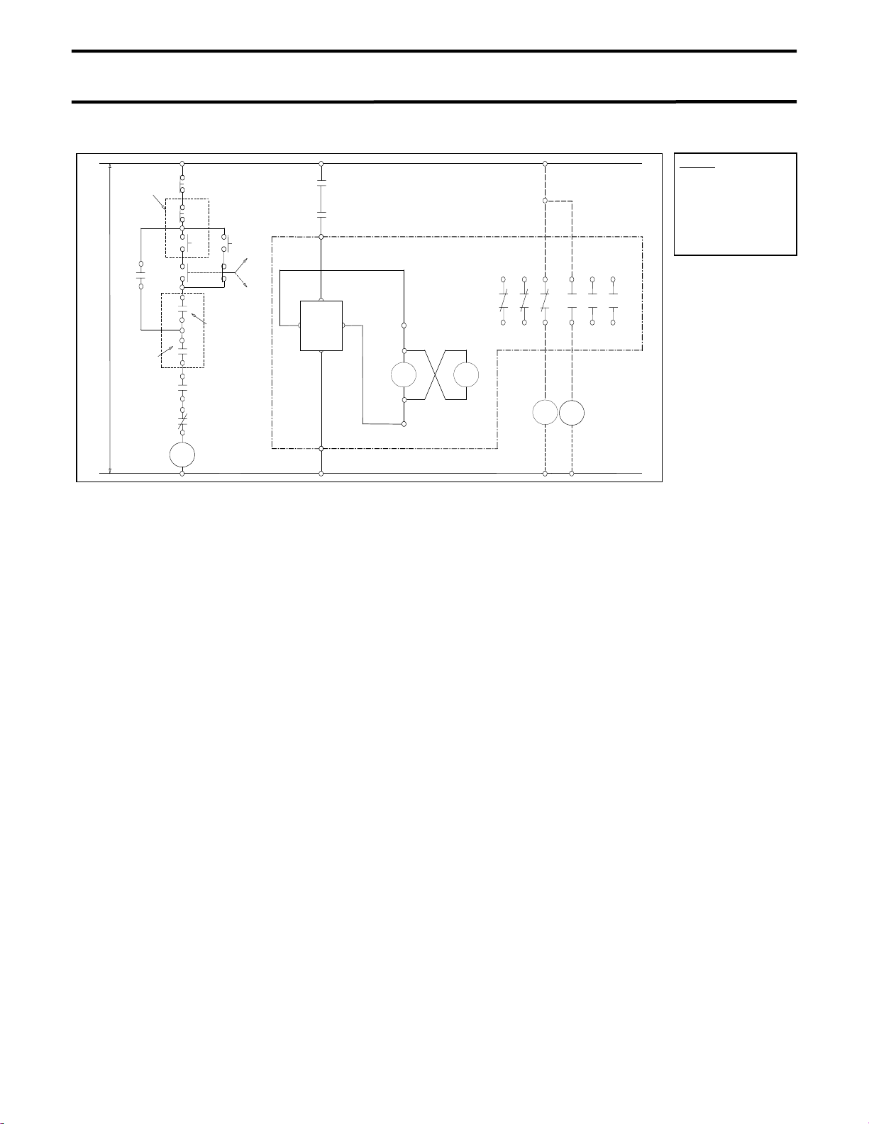
LEGEND
52 CC …. Closing Coil
T1-T4 ….. Terminal Block
R S T
Vacuum Bottles
U V W
A1-A2…... Closing Supply
AC/DC
T4
T3
T2
T1
52
CC
52
CC
16 15 14 13 12 11
26 25 24 23 22 21
uxiliar
Switch
56
Drive Unit
12
1 A2
Closing Supply
AC/DC
Figure 8 – Internal Connection of the Normally Energized Type
T1
1
2
52
CC
TIMER
T2
LEGEND
52 CC …. Closing Coil
T1-T2 ….. Terminal Block
A1-A2…... Closing Supply
AC/DC
VOLTAGE
DETEC
SWITCHING
OSCILLATION
POWER
Figure 9 – Configuration of the Drive Unit
Page 19
A
Phone: 800.894.0412 - Fax: 888.723.4773 - Web: www.ctiautomation.net - Email: info@ctiautomation.net
OPERATION Page 15
LEGEND
Remote
Opera ti on
Swit ch
100/110V
200/220V
Stop
C/DC
Interlock
CR
OFF
OFF
ON
Star t
Interlock
DrS
(Door Switch)
2E (Overl oad)
CR
ON
Local
Remote
A1
Dri ve
Unit
A2
CR
CR
52
CC
T1
T2
Auxil iary
Switch
52
CC
16 15 14 13 12 11
26 25 24 23 22 21
GL
RL
VCTT
52 CC …. Closing Coil
T1-T2 ….. Terminal Block
GL ……… Green Light
RL ……… Red Light
CR……… Control Relay
A1-A2…... Closing Supply
AC/DC
Figure 10 - Standard Operation Circuit of the Normally Energized Type.
Page 20

Phone: 800.894.0412 - Fax: 888.723.4773 - Web: www.ctiautomation.net - Email: info@ctiautomation.net
Page 16 MAINTENANCE
MAINTENANCE PROGRAM
In order to ensure continued reliable and safe
operation of the equipment, a program of
periodic maintenance must be established.
Operating and environmental conditions will
usually dictate the frequency of inspection
required. NFPA Publication 70B "Electrical
Equipment Maintenance" may be used as a
guide for setting up the maintenance program.
DANGER
WARNING
WARNING
NOTE: Refer to the SAFETY section of this
manual for important information.
Contact with energized
components can cause
severe injury, death and
property damage. Turn off
and lock out primary and
control circuit power before
servicing.
Improper maintenance can
cause severe injury, death
and property damage. Only
qualified and authorized
persons are to install,
operate or service this
equipment.
Grease is conductive. Do
not allow grease or any
other substances to
contaminate insulating
materials. Contaminated
insulators can allow a
short-circuit or ground
fault to occur.
MAINTENANCE RECORD
Keep a permanent record of all maintenance
work. At a minimum, this record should include
information on:
1. Items inspected
2. Reports of any testing
3. Equipment condition
4. Corrective actions or adjustments
5. Date of work
6. Comments
The degree of detail of the record will depend
somewhat on the operating conditions.
SERVICING EQUIPMENT
For your safety, turn off and lock out main and
control circuit power before servicing the
contactor. Certain minimum safety procedures
must be followed:
1. Only qualified personnel should attempt
this service.
2. Never perform service on or next to
exposed components energized with line
voltage.
WARNING
Failure to adhere to these
safety procedures can
result in severe injury,
death and property
damage.
Page 21

Phone: 800.894.0412 - Fax: 888.723.4773 - Web: www.ctiautomation.net - Email: info@ctiautomation.net
MAINTENANCE Page 17
RECOMMENDED INSPECTION AND
MAINTENANCE TYPES
NOTE: Refer to the SAFETY section of this
manual for important information.
1. Acceptance Inspection
This inspection confirms that the contactor is
complete, correct as specified and
undamaged from shipment. The procedure
for this inspection is outlined in the
RECEIVING, INSPECTION AND
HANDLING section of this manual.
2. Patrol Inspection
Inspection is made of the condition of the
contactor while it is energized. Check that
no unusual sounds or smells exist externally.
Check for any abnormal discoloration due to
overheating. Inspect for signs of damage to
the insulation frame, OPEN/CLOSE indicator
and other components.
Inspection Frequency:
3. Periodic Inspection
Inspection is performed with the contactor
de-energized. The lubrication of sliding and
rotating parts is checked and the mechanism
is lubricated if needed.
Inspection Frequency:
or every 20,000 operations (normal).
NOTE: Refer to Table 2 for the schedule of
Periodic Inspections.
4. Unscheduled Inspection
Inspections are implemented as required.
Inspection Frequency:
NOTE: The inspection frequency and points
to be inspected may vary from the
above recommendations depending
on the status of use, frequency of
switching and other factors.
Once every 6 months
Once every 1-2 years
As needed
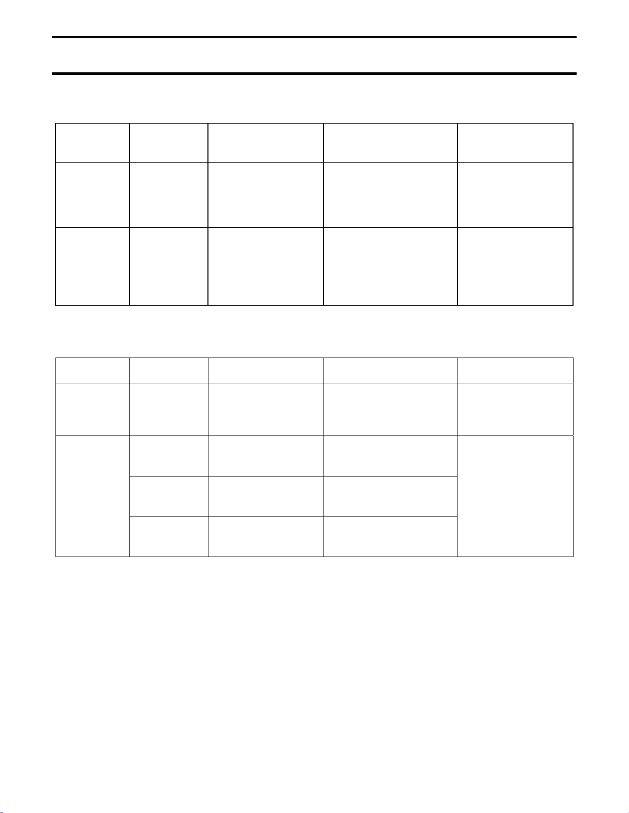
Table 1 - Tightening Torque
Screw Nominal
Diameter
M4 15-20 kgf-cm (13-17 in-lb)
M5 30-40 kgf-cm (26-34 in-lb)
M6 50-65 kgf-cm (43-56 in-lb)
M8 120-150 kgf-cm (9-11 ft-lb)
M10 250-315 kgf-cm (18-23 ft-lb)
M12 450-565 kgf-cm (32-41 ft-lb)
Tightening Torque
Page 22

Phone: 800.894.0412 - Fax: 888.723.4773 - Web: www.ctiautomation.net - Email: info@ctiautomation.net
Page 18 MAINTENANCE
Table 2 - Check Points for Periodic Inspection
Check
Point
Operating
Mechanism
Dust or
Electro-
Closing coil Visual inspection. Check for discoloration,
Spring Visual inspection. Check for rust,
Check Item Check Method Criteria Disposition
Loose bolts,
nuts or
screws
foreign
matter inside
magnets
Tighten using
screwdriver or
wrench.
Visual inspection. The contactor should be
Visual inspection. Check for rust,
Make sure all bolts,
nuts and screws are
tight.
clean and contain no
foreign matter.
discoloration, wear, or
loose mountings.
and burned parts.
deformation,
discoloration, or
damage.
Tighten if loose.
See Table 1 for
tightening torque
specifications.
Wipe with a clean
dry cloth.
Wipe with a clean
dry cloth.
Wipe with a clean
dry cloth.
Wipe with clean dry
cloth. Lubricate if
necessary.
Smooth
operation
Main Circuit Terminals
and movable
conductors.
Loose bolts,
nuts or
screws
Vacuum
contact wear.
Vacuum
level.
Visual inspection or
touch. Check
lubrication.
Visual inspection.
Tighten using
screwdriver or
wrench.
Tighten using a
wrench.
See Electrical
Service Life (Page
23).
Apply 10kV AC for 1
minute.
Make sure moving parts
operate smoothly.
Make sure there is no
discoloration or loose
fasteners.
Make sure all bolts,
nuts and screws are
tight.
Check contact wear and
wipe.
Check vacuum level by
withstand voltage test.
Apply a small
amount of
lubrication.
Check the cause
and repair. Tighten
connections to
contactor. See
(Table 1) for
tightening torque
specifications.
See Table 1 for
tightening torque
specifications.
Replace vacuum
interrupter.
If breakdown occurs,
contact Toshiba.
Page 23

Phone: 800.894.0412 - Fax: 888.723.4773 - Web: www.ctiautomation.net - Email: info@ctiautomation.net
MAINTENANCE Page 19
Table 2 – Check Points for Periodic Inspection (cont.)
Check
Point
Main Circuit Dust on
Insulation
Frame and
Flanges
Control
Circuits
Drive unit Visual inspection. Check for overheating
Check Item Check Method Criteria What to do
Visual inspection. Make sure there is no
surface of
vacuum
interrupter
Dust, foreign
matter or
damage
Auxiliary
Switch
Visual inspection. Make sure there is no
See Table 3. Contact wear and wipe.
dust on the surface.
dust, foreign matter or
breakage.
Make sure there is no
dust.
and discoloration.
Wipe with a clean,
dry cloth.
Wipe with a clean,
dry cloth. If
damaged, contact
Toshiba.
Replace if wear or
damage is
excessive. See
Table 1 for
tightening torque
specifications
Replace if damaged.
Wiring Visual inspection.
Tighten using a
screwdriver.
Insulation
Resistance
Measurement
Resistance
Resistance
from main
circuit to
ground
from control
circuits to
ground
Measure insulation
resistance between
phases, between
electrodes, and
between circuits and
ground. Megger test
at 1000V.
Measure insulation
resistance between
circuits and ground.
Megger test at
500V.
Check for discoloration
and tightness.
Resistance should be
50MΩ or greater.
Resistance should be
1MΩ or greater.
Repair if
disconnected.
Tighten if loose.
See Table 1 for
tightening torque
specifications.
If the insulation
resistance is low,
wipe off the vacuum
interrupter and other
insulation surfaces
with a clean dry
cloth and then
repeat the test. If
necessary, replace
faulty parts.
Page 24
Phone: 800.894.0412 - Fax: 888.723.4773 - Web: www.ctiautomation.net - Email: info@ctiautomation.net
Page 20 MAINTENANCE
Table 2 – Check Points for Periodic Inspection (cont.)
Check
Point
Dielectric
Strength
Open/Close
Operation
Table 3 - Gap/Wipe Standard Values (contactor in new condition).
Parts
Vacuum
Interrupter
Check Item Check Method Criteria What to do
Measure
main circuit
--- Perform open/close
Normally
energized
type
Measure dielectric
strength between
phases and between
circuits and ground.
operation by electric
operation test to
confirm the correct
operation.
Gap Wipe Allowable Wear
0.091-0.098 in.
(2.3-2.5 mm)
10kV AC or 14kV DC for
1 minute.
--- If not normal, check
0.091-0.102 in.
(2.3-2.6 mm)
If breakdown occurs,
contact Toshiba.
and repair. If
necessary, replace
faulty parts.
0.051 in. (1.3 mm)
Auxiliary
Switch
a-contact
b-contact
Delayed
b-contact
0.157±0.016 in.
(4±0.4 mm)
0.157±0.016 in.
(4±0.4 mm)
0.098±0.012 in.
(2.5±0.3 mm)
0.118±0.012 in.
(3±0.3 mm)
0.118±0.012 in.
(3±0.3 mm)
0.177±0.020 in.
(4.5±0.5 mm)
---
Page 25

Phone: 800.894.0412 - Fax: 888.723.4773 - Web: www.ctiautomation.net - Email: info@ctiautomation.net
MAINTENANCE Page 21
VACUUM CHECK
A sufficient level of vacuum is necessary for
proper performance of the vacuum interrupters.
Although vacuum leaks are rare, the vacuum
integrity should be checked periodically. The
relationship between dielectric breakdown
voltage of the contact gap and internal vacuum
interrupter pressure has been found to be
generally predictable. Therefore, vacuum
interrupter integrity is checked by performing a
high potential test across the open gap of the
interrupter.
TEST EQUIPMENT:
Toshiba offers a compact vacuum checker (Type
CI35-1D, Figure 11) which enables a quick and
easy check on vacuum interrupter internal
pressure. Alternatively, any commercially
available AC high potential tester may be used
which is capable of delivering at least 25 milliamperes at 10 kV for a period of one minute.
PRECAUTIONS:
Applying abnormally high voltage across a pair
of contacts in vacuum may produce X-rays. The
radiation may increase with the increase in
voltage and/or decrease in contact spacing. Xradiation produced during this test with
recommended voltage and normal contact
spacing is extremely low and well below the
maximum permitted by standards. As an
additional safety measure, however, it is
recommended that all personnel keep at least 1
meter (3.3 ft) away from the vacuum circuit
breaker while this test is performed.
WARNING
Radiation exposure hazard.
X-rays may cause illness or
injury. Stay at least 1 meter
(3.3 ft) away from the circuit
breaker during the vacuum
check test.
WARNING
TEST PROCEDURE:
1. The contactor should be disconnected from
the main circuit and be in the OFF position.
2. Connect all the line side primary terminals
together and to the output of the vacuum
checker or AC hi-pot machine. Connect all
the load side primary terminals together and
to the ground terminal of the vacuum
checker or AC hi-pot machine.
3. Increase the voltage from zero to 10kV AC at
a rate of approximately 1kV per second.
Hold the voltage at this value for 1 minute
and observe the current drawn by the
interrupter. See Figure 12.
4. Decrease the voltage back to zero.
Figure 11 - Toshiba Portable Vacuum
Checker
Hazardous voltages are
present during dielectric
testing which can result in
severe injury or death.
Only qualified personnel
should conduct this testing.
Page 26

Phone: 800.894.0412 - Fax: 888.723.4773 - Web: www.ctiautomation.net - Email: info@ctiautomation.net
Page 22 MAINTENANCE
CRITERIA:
1. If a current flow above 5 milli-amperes is
observed or if breakdown occurs, one or
more of the interrupters has insufficient
vacuum and must be replaced.
Exception: If the current exceeds 5 milli-
amperes the first time the voltage is brought
up, reduce the voltage to zero and increase it
again. It may be necessary to repeat this
procedure a few times.
2. If the contactor fails to meet criteria 1, then
repeat the test on each pole separately to
identify the damaged interrupter or
interrupters.
3. If the voltage can be held for 1 minute and
the current flow does not exceed 5 milliamperes, the interrupter has a sufficient
vacuum level.
After the test is complete, discharge any residual
static charge from the primary terminals of the
circuit breaker.
If a vacuum checker or AC hi-pot tester is not
available, a DC hi potential test may be
conducted. If a DC test is conducted, the test
voltage must be increased to 14kV DC. The test
duration for DC tests and the criteria for
acceptance remain the same as for AC tests.
WARNING
Do not use DC hi-pot
testers which employ
unfiltered half-wave
rectifiers. The peak
voltages produced by these
testers may exceed the
recommended value of
14kV. This can result in the
production of harmful Xrays and may invalidate the
test results.
1 minute
10kV AC
(14kV DC)
Voltage
Zero
10 sec 10 sec
Time
Figure 12 - Application of Test Voltage for
Vacuum Check
Page 27

Phone: 800.894.0412 - Fax: 888.723.4773 - Web: www.ctiautomation.net - Email: info@ctiautomation.net
MAINTENANCE Page 23
ELECTRICAL SERVICE LIFE
The electrical service life of the vacuum
interrupter is defined by the electrode wear and
the number of open/close operations
(mechanical life).
To determine electrode wear, measure the
distance between the lever and washer in the
closed (ON) state, as shown in Figure 13. This
dimension is called the “wipe”. If the 1.0mm
contact wear gauge cannot be inserted, then
the end of the service life has been reached.
The maximum number of open/close operations
is 500,000 regardless of the magnitudes of the
currents interrupted. Contact Toshiba for
information regarding replacement of the
vacuum interrupters.
The drive unit and the closing coils also have
an electrical service life of 500,000 operations.
As a result, these parts should be replaced
around 500,000 operations.
MECHANICAL SERVICE LIFE
The normally energized type has a mechanical
service life of 2.5 million operations. The
mechanical service life of the vacuum
interrupters is 500,000 operations.
For the components listed in Table 4,
replacement or detailed inspection and cleaning
are recommended after the indicated number of
operations.
Isolation
Flange
A
Figure 13 - Wipe Measurement
Table 4 - Recommended Part Replacement
Intervals
Part Name Number of Operations
for Replacement
Vacuum Interrupter 500,000
Auxiliary Switch 200,000
Moveable Core Detailed inspection and
cleaning every 500,000
operations.
Stationary Core Detailed inspection and
cleaning every 500,000
operations.
Closing Coil 500,000
Flexible Conductor 500,000
SERVICE LIFE – CAPACITOR SWITCHING
Switching of the capacitor loads produces
severe conditions for contactors, such as high
frequency inrush current and phase-to-phase
recovery voltage more than twice the normal
voltage.
The criterion for the maximum number of the
capacitor current switching operations is shown
in Figure 14. The vacuum interrupter should be
replaced when the number of switching
operations in the graph is reached.
10
8
6
4
2
Switching Life (ten thousand)
1
20 40 60 200 400 600
10 100 1000
Switching Current (A)
Figure 14 - Capacitor Switching Life
Page 28

Phone: 800.894.0412 - Fax: 888.723.4773 - Web: www.ctiautomation.net - Email: info@ctiautomation.net
Page 24 DISPOSAL AND STORAGE
STORAGE
If the contactor is to be stored for any length of
time prior to installation, the following
precautions should be taken.
1. The original packing should be restored, if
possible.
2. Do not subject the equipment to moisture or
sunrays. Store in cool, clean, and dry
location.
3. Place a dust cover over the contactor
packaging to protect against dirt and
moisture.
4. Store in an upright position.
INSPECTION DURING STORAGE
Routine scheduled inspection is necessary if
storage is for an extended period. The unit
should be checked for condensation, moisture,
corrosion, and vermin.
Prior to installation, the contactor should be
carefully examined for evidence of physical
damage, corrosion, or other deterioration. Refer
to the PRE-ENERGIZATION Section of this
manual.
The MAINTENANCE section of this manual
describes various types of inspections
recommended for this contactor during the
operation period.
DISPOSAL
Contact your state environmental agency for
details on disposal of electrical components and
packaging in your particular area.
Page 29

Phone: 800.894.0412 - Fax: 888.723.4773 - Web: www.ctiautomation.net - Email: info@ctiautomation.net
SPECIFICATIONS Page 25
Table 5 - Ratings
Items HCV-1JBU HCV-1KAU
Rated Insulation Voltage kV 1.5
Rated Operation Voltage V 208-1500
Rated Operational Current A 600 720
Rated Frequency Hz 50/60
Rated Making Current kA 6.0
(close 100 times)
Rated Breaking Current kA 4.8
(close-open 25 times)
Rated Insulation Level kV AC 10 Impulse 45 AC 10 Impulse 30
Rated Short-Time Current kA 9.0 – 1 sec.
3.6 – 30 sec.
Method of Operation Non-latch
Mechanical Operation Million 2.5
Electrical Operation Million 0.5
Operational Voltage Standard 100-240V AC/DC
Auxiliary Switch 3 N.O. – 3 N.C.
Switching Frequency Times/h 1200
(close 100 times)
(close-open 25 times)
7.2
5.76
10.8 – 1 sec.
4.3 – 30 sec.
Page 30

Phone: 800.894.0412 - Fax: 888.723.4773 - Web: www.ctiautomation.net - Email: info@ctiautomation.net
WARRANTY AND LIMITATION OF LIABILITY Page 26
Toshiba International Corporation ("Company") warrants that all equipment and parts described herein will be free
from defects in materials and workmanship. THIS WARRANTY WILL EXPIRE EIGHTEEN (18) MONTHS AFTER
THE DATE ON WHICH SUCH EQUIPMENT AND PARTS (EXCLUDING REPAIRED OR REPLACEMENT
EQUIPMENT AND PARTS FURNISHED PURSUANT TO THIS WARRANTY) ARE SHIPPED BY THE COMPANY
TO THE INITIAL PURCHASER OR TWELVE (12) MONTHS AFTER SUCH EQUIPMENT AND PARTS
(EXCLUDING REPAIRED OR REPLACEMENT EQUIPMENT AND PARTS FURNISHED PURSUANT TO THIS
WARRANTY) ARE FIRST PLACED IN OPERATION, WHICHEVER PERIOD FIRST EXPIRES.
The Company will, at its option, repair or replace such equipment or part which is defective under the terms of the
foregoing warranty, free of charge; provided
defect, and (2) furnishes the Company satisfactory proof thereof, and (3) establishes that the equipment or part has
been properly installed, maintained and operated within the limits of rated capacity and normal usage and in
accordance with this manual, and (4) if requested by the Company, returns the defective equipment or part to the
Company and pays all expenses incurred in connection with such return. The repaired or replacement equipment or
part will be delivered, free of charge, to the purchaser F.O.B. the Company's warehouse or, at the Company's
option, F.O.B. a Company authorized service shop, not loaded on truck or other carrier. The purchaser will pay the
costs applicable to the equipment or part following such delivery, including, without limitation, all handling,
transportation, assembly, insurance, testing and inspection charges.
THE FOREGOING OBLIGATION TO REPAIR OR REPLACE EQUIPMENT PARTS SHALL BE THE SOLE AND
EXCLUSIVE REMEDY OF THE PURCHASER, ITS CUSTOMERS AND USERS OF THE EQUIPMENT AND
PARTS FOR BREACH OF THE FOREGOING WARRANTY. THE COMPANY WILL HAVE NO OBLIGATIONS TO
DISASSEMBLE ANY EQUIPMENT OR PART WHICH IS DEFECTIVE WITHIN THE TERMS OF THE ABOVE
WARRANTY OR TO INSTALL ANY REPAIRED OR REPLACEMENT PART OR EQUIPMENT OR TO PAY ANY
COSTS INCURRED IN CONNECTION WITH ANY SUCH DISASSEMBLY OR INSTALLATION. THE COMPANY,
TOSHIBA CORPORATION AND THEIR SUPPLIERS AND SUBCONTRACTORS HEREBY DISCLAIM ALL
OTHER EXPRESS, STATUTORY AND IMPLIED WARRANTIES, INCLUDING, WITHOUT LIMITATION, ALL
EQUIPMENT AND PARTS FURNISHED PURSUANT TO THE FOREGOING WARRANTY AND ALL IMPLIED
WARRANTIES OF MERCHANTABILITY.
The total liability of the Company, Toshiba Corporation and their suppliers and subcontractors for any
loss, damage or claim, whether in contact, tort (including negligence and liability without fault), or
otherwise, arising out of, connected with or resulting from the equipment and parts described in this
manual or the performance or breach of any contract for the sale or supply of such equipment and
parts, or from the design, manufacture, sale, delivery, resale, installation, technical direction or
supervision of installation, inspection, testing, repair, replacement, operation, maintenance or use of
any such equipment or part or any service relating thereto furnished by the Company shall not in any
event exceed the price allocable to the equipment, part or service which gives claim, loss or damage.
In no event, whether as a breach of contract or warranty, alleged negligence, liability without fault, or
otherwise, shall the Company, Toshiba Corporation or their suppliers or subcontractors be liable for
special or consequential damages, including, without limitation, loss or profits or revenue, loss of
equipment described herein or any associated equipment, cost of capital, cost of substitute equipment
or parts, facilities or services, down-time costs, labor costs or claims of customers of the purchaser for
such damages.
the purchaser (1) promptly notifies the Company in writing of such
 Loading...