

Toshiba GX9 Installation & Operation Manual
TOSHIBA
DN: 66893-001
March, 2014
GX9 ASD Install & Op Manual
GX9 ASD
I
NSTALLATION
& O
PERATION
M
ANUAL


Document Number: 66893-001
March, 2014
GX9 ASD
Installation & Operation Manual


Introduction
Congratulations on the purchase of the GX9 Adjustable Speed Drive!
The GX9 Adjustable Speed Drive (ASD) is a solid-state AC drive that features Toshiba International
Corporation’s (TIC) Virtual Linear Pump Technology (VLP Technology) and Vector Control
algorithms. The Virtual Linear Pump Technology and Vector Control algorithms provide easy setup,
enhanced reliability, and precise control und er th e mo st d emand ing cond itions — all wh ile enab lin g the
motors of the system to develop high starting torque and providing compensation for motor slip. The
result is setup ease, smooth starts, and highly efficient operation.
The Virtual Linear Pump Technology algorithm was designed to remove the guess work that is
normally associated with the setup of pumping systems. It allows for direct, linear, and precise pump
curve responses at any flow or pressure setting. This is accomplished without the normal concerns of
the adverse effects of conventional pumping system control response curves.
Using Virtual Linear Pump Technology, the system seamlessly and easily adapts to peak load
demands while maintaining the same d egree of high performa nce o utput and relia bility acro ss the en tire
load range - all without any user intervention!
The GX9 ASD is a very powerful tool, yet surprisingly s i mple t o o perate. Th e us er-friendly Electronic
Operator Interface (EOI) of the GX9 ASD has an easy-to-read LCD screen and a high-intensity LED
display. The EOI provides easy access to the many monitoring and programming features of the GX9
ASD.
The GX9 ASD uses digitally-controlled pulse width modulation. The programmable functions may be
accessed via the easy-to-use menu, via the Direct Access Numbers (see pg. 75), or using
communications via a host PC. The ease of system access to the monitoring and control features
combined with Toshiba’s high-performan ce software, del ivers u nparal leled mo tor cont rol pr ecision and
reliability.
This manual has been prepared for the GX9 ASD installer, user, and maintenance personnel. This
manual may also be used as a reference guide or for training. With this in mind, use this manual to
develop a system familiarity before attempting to install or operate the device.

Importa nt Notice
The instructions contained in this manual are not intended to cover all details or variations in equipment
types, nor may it provide for every possible contingency concerning the installation, operations, or
maintenance of this equipment. Should additional information be required, contact the Toshiba
Customer Support Center.
The contents of this manual shall not become a part of or modify any prior or existing agreement,
commitment, or relationship. The sales contract contains the entire obligation of Toshib a Inter national
Corporation. The warranty contained in the contract between the p arties is the sole warranty o f Toshiba
International Corporation and any statements contained herein do not create new warranties or modify
the existing warranty.
Any electrical or mechanical modifications to this equipment without the prior written consent of
Tos hiba International Corporation may void all warranties and may void the UL/CSA listing or
other safety certifications. Unauthorized modifications may also result in a safety hazard or
equipment damage.
Misuse of this equipment could result in injury and equipment damage. In no event will Toshiba
International Corporation be responsible or liable for direct, indirect, special, or consequential
damage or injury that may result from the misuse of this equipment.

About This Manual
This manual was written by the Toshiba International Corporation Technical Publications Group. This
group is tasked with providing technical documentation for the GX9 Adjustable Speed Drive. Every
effort has been made to provide accurate and concise information to you, our customer.
At T oshiba International Corpo ration we are cont inuously striving for better ways to meet the constan tly
changing needs of our customers. E-mail your comments, questions, or concerns about this publication
to Technical-Publications-Dept@tic.toshiba.com.
Manual’s Purpose and Scope
This manual provides information on how to safely install, operate, maintain, and dispose of your
GX9 Adjustable Speed Drive. The information provided in this manual is applicable to the
GX9 Adjustable Speed Drive only.
This manual provides information on the various features and functions of this powerful cost-saving
device, including
• Installation,
• System operation,
• Configuration and menu options, and
• Mechanical and electrical specifications.
Included is a section on g eneral safet y ins truction s that des cribe the warni ng label s and symbols that ar e
used on the device and throughout the manual. Read the manual completely before installing, operating,
performing maintenance, or disposing of this equipment.
This manual and the accompanying drawings should be considered a permanent part of the equipment
and should be readily available for reference and review. Dimensions shown in the manual are in
English an d/or the metric equival ent.
Because of our commitment to continu ous improvement, Toshiba International Corporation reserves the
right, without prior notice, to update information, make product changes, or to discontinue any product
or service identified in this publication.
Toshiba Internat i onal Corporation (TIC) shall not be liable for direct, indirect, special, or
consequential damages resulting from the use of the information contained within this manual.
This manual is copyrighted. No part of this manual may be photocopied or reproduced in any form
without the prior written consent of Toshiba International Corporation.
© Copyright 2014 Toshiba International Corporation.
TOSHIBA® is a registered trademark of Toshiba Corporation. All other product or trade references
appearing in this manual are registered trademarks of their respective owners.
All rights reserved.
Printed in the U.S.A.

Contacting TIC’s Customer Support
TOSHIBA INTERNATIONAL CORPORATION
GX9 Adjustable Speed Drive
Please complete the Warranty Card supplied with the GX9 ASD and return it to Toshiba International
Corporation by prepaid mail. This will activate the 12-month warranty from the date of installation; but, shall not
exceed 18 months from the shipping date.
Complete the following information and retain for your records.
Model Number: ______________________________________________________________________
Serial Number: ___________ _________________ ___ ___ _________________ ___ ________________
Project Number (if applicable):_________________________________________________________
Date of Installation: ______ __ _________________ ___ _________________ ___ ___ _______________
Inspected By: _______________________________________________________________________
Name of Application: ________________________________________________________________
Center
Toshiba International Corporation’s Customer Support Center can be contacted to obtain help in
resolving any Adjustable Speed Drive system problem that you may experience or to provide
application information.
The Support Center is open from 8 a.m. to 5 p.m. (CST), Monday through Friday. The Center’s toll free
number is US (800) 231-1412/Fax (713) 937-9349 CAN (800) 872-2192 MEX 01 (800) 527-1204.
For after-hours support follow the directions in the outgoing message when calling.
You may also contact Toshiba International Corporation by writing to:
Toshiba International Corporation
13131 West Little York Road
Houston, Texas 77041-9990
Attn: ASD Product Manager.
For further information on Toshiba International Corporation’s products and services, please visit our
website at www.toshiba.com/ind/.

Table of Contents
General Safety Information .............................. ..... .................................. ...... .........................1
Safety Alert Symbol ........................................................... .................................. ...... ..... ...1
Signal Words ......................................................................................................................1
Special Symbols .................................................................................................................2
Equipment Warning Labels ................................................................................................2
Qualified Personnel ............................................................................................................2
Equipment Inspection .........................................................................................................3
Handling and Storage .........................................................................................................3
Disposal ..............................................................................................................................3
Installation Precautions ...........................................................................................................4
Location and Ambient Requirements .................................................................................4
Mounting Requirements .....................................................................................................4
Conductor Routing and Grounding Precautions .................................................................5
Power Connections Precautions .............................. ...... ..... .................................. ...... ..... ...5
Protection ............................................................................................................................6
Dynamic Braking Resistor Requirements ..........................................................................6
Residual Voltage Warning ..................................................................................................7
System Integration Precautions ..............................................................................................8
Personnel Protection ...........................................................................................................8
System Setup Requirements ...............................................................................................9
Operational and Maintenance Precautions .........................................................................10
Motor Characteristics ............................................................................................................11
Motor Autotuning .............................................................................................................11
Pulse Width Modulation Operation ..................................................................................11
Low Speed Operation .......................................................................................................11
Overload Protection Adjustment ......................................................................................11
Operation Above 60 Hz ....................................................................................................12
Power Factor Correction ........................................................... ...... ..... .............................12
Light Load Conditions ......................................................................................................12
Motor/Load Combinations ...............................................................................................12
Load-Produced Negative Torque ......................................................................................13
Motor Braking ..................................................................................................................13
GX9 ASD Characteristics .....................................................................................................14
Over-Current Protection ...................................................................................................14
GX9 ASD Capacity ..........................................................................................................14
Using Vector Control ........................................................................................................14
Local/Remote Operation ...................................................................................................14
GX9 ASD Installation and Operation Manual i

Installation and Connections ................................................................................................15
Installation Notes ..................................................... ...... ..... .................................. ...... .... ..15
Mounting the ASD ............................................................................................................16
Connecting the ASD .........................................................................................................17
Power Connections .......................................................... ...... .................................. ..... .17
System Grounding..........................................................................................................19
Lead Length Specifications............................................................................................19
I/O and Control .................................................................................................................20
Terminal Descriptions....................................................................................................21
GX9 ASD Control ............................................................................................................25
CNU1 and CNU2 Pinout................................................................................................26
CN3 Pinout.....................................................................................................................26
CN7 Pinout.....................................................................................................................27
I/O Circuit Configurations.............................................................................................28
Startup and Test .............................................................................................................29
Save User Settings .........................................................................................................29
Typical Connection Diagram ............................................................................................30
Electronic Operator Interface ..............................................................................................31
EOI Operation ............................................... ..... ...... .................................. ...... .................31
Battery Backup .................................................................................................................31
EOI Features ..................... ..... ...... .................................. ..... ...... .................................. ......33
LED/LCD Screens .........................................................................................................34
Using the LCD Screen ...................................................................................................35
EOI Remote Mounting ....................................................... ...... .................................. ..... .36
Remote EOI Hardware...................................................................................................36
EOI Installation Precautions .............................................................................. ...... ..... .37
EOI Remote Mounting w/o the ASD-MTG-KIT9.........................................................37
EOI Remote Mounting Using the ASD-MTG-KIT9.....................................................38
System Configuration and Menu Options ...........................................................................39
Root Menus .......................................................................................................................39
Frequency Command Mode...........................................................................................39
Monitor Mode................................................................................................................41
Main Monitor Selections.................................................. ...... ...... ................................. .43
Program Mode Menu Navigation ..................................................................................44
System Operation ...................................................................................................................60
Startup Wizard ..................................................................................................................60
Operation (Local) ..............................................................................................................60
Default Setting Changes ............................... ..... .................................. ...... .......................61
Startup Wizard Requirements .............................................................................................62
Running the Startup Wizard .............................................................................................62
Command Mode and Frequency Mode Control .................................................................66
Command Control (F003) ................................................................................................66
Frequency Control (F004) ................................................................................................67
Command and Frequency Control Selections................................................................ 68
ii GX9 ASD Installat ion and Operation Manual

Command and Frequency-Control Override Hierarchy.................................................68
Command Control Selections ........................................................................................69
Frequency Control Selections........................................................................................69
Virtual Linear Pump Setup ..................................................................................................71
Direct Access Parameter Information .................................................................................75
Direct Access Parameters/Numbers .................................................................................75
Alarms, Trips, and Troubleshooting ..................................................................................223
Alarms and Trips ............................................................................................................223
User Notification Codes .................................................................................................224
Alarms .............................................................................................................................225
Trips/Faults .....................................................................................................................228
Viewing Trip Information........................................... ..... ...... .................................. ....233
Clearing a Trip ..................................... ...... ..... .................................. ...... .....................233
Part Numbering Convention and Ordering Information ................................................234
Cable/Terminal Specifications ............................................................................................236
Voltage/Current Specifications ...........................................................................................237
Enclosure Dimensions/Weight ............................................................................................238
GX9 ASD Optional Devices ................................................................................................245
GX9 ASD Installation and Operation Manual iii

iv GX9 ASD Installation and Operation Manual
General Safety Information
DANGER
WARNING
CAUTION
CAUTION
DO NOT attempt to install, operate, maintain, or dispose of this equipment until you have read and
understood all of the product safety information and directions that are contained in this manual.
Safety Alert Symbol
The Safety Alert Symbol is comprised of an equilateral triangle enclosing an exclamation mark. This
indicates that a potential personal injury hazard exists.
Signal Words
Listed below are the signal words that are used throughout this manual followed by their descriptions
and associated symbols. When the words DANGER, WARNING, or CAUTION are used in this
manual, they will be followed by important safety information that must be followed carefully.
The word DANGER preceded by the safety alert symbol
indicates that an imminently hazardous situation exists that, if
not avoided or if instructions are not followed precisely, will
result in serious injury to personnel or loss of life.
The word WARNING preceded by the safety alert symbol
indicates that a potentially hazardous situation exists that, if
not avoided or if instructions are not followed precisely, could
result in serious injury to personnel or loss of life.
The word CAUTION preceded by the safety alert symbol
indicates that a potentially hazardous situation exists that, if
not avoided or if instructions are not followed precisely, may
result in minor or moderate injury.
The word CAUTION without the safety alert symbol indicates
a potentially hazardous situation exists that, if not avoided or if
instructions are not followed precisely, may result in
equipment and property damage.
GX9 ASD Installation and Operation Manual 1
Special Symbols
T o identify special hazards, other symbols may app ear in conjunction with the DANGER, WARNING,
and CAUTION signal words. These symbols indicate areas that require special and/or strict adherence
to the procedures to prevent serious injury to personnel or loss of life.
Electrical Hazard Symbol
A symbol that is comprised of an equilateral triangle enclosing
a lightning bolt indicates a hazard of injury from electrical
shock or burn.
Explosion Hazard Symbol
A symbol that is comprised of an equilateral triangle enclosing
an explosion indicates a hazard of injury from exploding parts.
Equipment Warning Labels
DO NOT attempt to install, operate, perform maintenance, or dispose of this equipment until you have
read and understood all of the product labels and user directions that are contained in this manual.
Warning labels that are attached to the equipment will include the exclamation mark within a triangle.
DO NOT remove or cover any of these labels. If the labels are damaged or if additional labels are
required, contact the Toshiba Customer Support Center.
Labels attached to the equipment are there to provide useful information or to indicate an imminently
hazardous situation that may result in serious injury, severe property and equipment damage, or loss of
life if safe procedures or methods are not followed as outlined in this manual.
Qualified Personnel
Installation, operatio n, and mai nte nan ce sh al l be performed by Qualified Personnel Only. A Qualified
Person is one that has the skills and knowledge relating to the construction, installation, operation, and
maintenance of the electrical equipment and has received safety training on the hazar ds involv ed (Refer
to the latest edition of NFPA 70E for additional safety requirements).
Qualified Personnel shall:
• Have carefully read the entire manual.
• Be familiar with the construction and function of the ASD, the equipment being driven, and the
hazards involved.
• Be able to recognize and properly address hazards associated with the application of motor-driven
equipment.
• Be trained and authorized to safely energize, de-energize, ground, lock-out/tag-out circuits and
equipment, and clear faults in accordance with established safety practices.
• Be trained in the proper care and use of protective equipment such as safety shoes, rubber gloves,
hard hats, safety glasses, face shields, flash clothing, etc., in accordance with established safety
practices.
For further information on workplace safety, visit www.osha.gov.
2 GX9 ASD Installation and Operation Ma nual

Equipment Inspection
• Upon receipt of the equipment, inspect the packaging and equipment for shipping damage.
• Carefully unpack the equipment and check for parts that may have been damaged during shipping,
missing parts, or concealed damage. If an y discrepancies are discovered, it should b e noted with the
carrier prior to accepting the shipment, if possible. File a claim with the carrier if necessary and
immediately notify the Toshiba Customer Support Center.
• DO NOT install the ASD if it is damaged or if it is missing any component(s).
• Ensure that the rated capacity and the model number specified on the nameplate conform to the
order specifications.
• Modification of this equipment is dangerous and is to be performed by factory trained personnel
ONLY. When modifications are required contact the Toshiba Customer Support Center.
• Inspections may be required after moving equipment.
• Contact the Toshiba Customer Support Center to report discrepancies or for assistance if required.
Handling and Storage
• Use proper lifting techniqu es when moving the ASD; inclu ding pr operly si zing up th e load, getti ng
assistance, and using a forklift if required.
• Store in a well-ventilated location and preferably in the original packaging if the equipment will not
be used upon receipt.
• Store in a cool, clean, and dry location. Avoid storage locations with extreme temperatures, rapid
temperature changes, high humidity, moisture, dust, corrosive gases, or metal particles.
• The storage temperature range of the GX9 ASD is -13° to 149° F (-25° to 65° C).
• DO NOT store the unit in places that are exposed to outside weather conditions (i.e., wind, rain,
snow, etc.).
• Store in an upright position.
Disposal
Never dispose of electrical components via incineration. Contact your state environmental agency for
details on disposal of electrical components and packaging in your area.
GX9 ASD Installation and Operation Manual 3

Installation Precautions
Location and Ambient Requirements
• The ASD is intended for permanent installations only.
• Installation shall conform to the National Electrical Code (NEC) — Article 110 (Requirements
For Electrical Installations), all regulations of the Occupational Safety and Health
Administration, and any other applicable national, regional, or industry codes and standards.
Note: For ALL references to the National Electrical Code (NEC), see the latest release of
the National Electrical Code.
• Select a mounting location that is easily accessible, has adequate personnel working space, and
adequate illumination for adjustment, inspection, and maintenance of the equipment (refer to the
NEC Article 110-13).
• DO NOT mount the ASD in a location that would produce catastrophic results if it were to become
dislodged from its mounting location (equipment damage or injury).
• DO NOT mount the ASD in a location that would allow it to be exposed to flammable ch emicals or
gases, water, solvents, explosive/corrosive mists or gases, or other fluids.
• Avoid installation in areas where vibration, heat, humidity, dust, fibers, metal particles, or sources
of electrical noise are present.
• If a NEMA 1 installation, the system shall not be exposed to direct sunlight.
• Allow proper clearance spaces for installation. Do not obstruct the ventilation openings. Refer to
the section titled Installation and Connections on pg. 15 for further information on ventilation
requirements.
• The ambient operating temperature range of the GX9 ASD is 14° to 104° F (-10° to 40° C).
Mounting Requirements
•Only Qualified Personnel shall install this equipment.
• Install the unit in a secure and upright position in a well-ventilated area.
• As a minimum, the installation of the equipment shall conform to the NEC — Article 110 (NEC),
OSHA, as well as any other applicable national, regional, or indu stry codes an d standards.
• Installation practices shall conform to the latest revision of NFPA 70E Electrical Safety
Requirements for Employee Workplaces.
• It is the responsibility of the ASD installer/maintenance personnel to ensure that the unit is installed
into an enclosure that will protect personnel against electric shock.
4 GX9 ASD Installation and Operation Ma nual
Conductor Routing and Grounding
WARNING
DANGER
Precautions
• Use separate metal conduits for routing the input power, output power, and control circuits.
• A separate ground cable shall be run inside the conduit with the input power, output power, and
control circuits.
• If multiple conductors are used in parallel for the input or output power, each parallel set shall have
its own conduit and not share its conduit with other parallel sets (i.e., place U1, V1, W1, and a
ground wire in one condu it and U2, V2, W2 and a groun d wi re in ano t her; r efer to the N EC Arti cl e
300.20 and Article 310.4). National and local electrical codes shall be referenced if three or more
power conductors are run in the same conduit (refer to the NEC Article 310 adjustment factors).
• Under no circumstances in a multiple ASD or multiple motor system configuration shall the input
power or out put power cables of the system AS Ds or motors be routed within a shared conduit.
Each ASD and each motor shall have its own conduit for input power and output power cable
routing.
Note: National and local codes shall be referenced when running more than three
conductors in the same conduit.
• DO NOT connect CC to earth ground.
•Use the CC terminal as the return for analog input terminals VI, RX, and RR.
•Use the CC terminal as the return for output terminals FP, PP, and P24.
• Use the negative terminal of the AM, FM, and II terminals as the return for these analog inputs.
• Always ground the unit to prevent electrical shock and to help reduce electrical noise.
• It is the responsibility of the A SD install er/mainte nance person nel to p rovide pr oper gro undin g and
branch circuit protection in accordance with the NEC and any applicable local codes.
— The Metal Conduit Is Not An Acceptable Ground —
Power Connections Precautions
CONTACT WITH ENERGIZED WIRING WILL CAUSE
SEVERE INJURY OR LOSS OF LIFE.
• Turn off and lock-out/tag-out all power sources before connecting the power wiring to the
equipment.
• Ensure that all power sources are turned off and isolated in accordance with established lock-out/
tag-out procedures before connecting the 3-phase power source wiring to the ASD input terminals
and connect the ASD output terminals to a motor of the correct voltage and typ e for the applicat ion
(refer to the NEC Article 300 – Wiring Methods and Article 310 – Conductors For General
Wiring). Size the branch circuit conductors in accordance with the NEC Table 310.16.
• Ensure that the 3-phase input power is NOT connected to the output of the ASD. This will damage
the ASD and may cause injury to personnel.
• Ensure the correct phase sequence and the desired direction of motor rotation in the Bypass mode
(if applicable).
GX9 ASD Installation and Operation Manual 5

Protection
• Ensure that primary pr otection exists for th e inpu t wiri ng to t he equip ment. T his pro tection mu st b e
able to interrupt the available fault current from the power line. The equipment may or may not be
equipped with an input disconnect (op tio n).
• All cable entry openings must be sealed to reduce the risk of entry by vermin and to allow for
maximum cooling efficiency.
• External dynamic braking resistors must be thermally protected.
• If the ASD is supplied with a motor as a package, it then becomes a machine and has to meet the
Essential Health and Safety Requirements of the EU Machinery Directive, 2006/42/EC. It is also a
requirement that the system have an Emergency Off function that meets the requirements of EN
ISO 13850:2008, and that any local or regional requirements must be met.
• It is the responsibility of the ASD installer/maintenance personnel to set up the Emergency Off
braking system of the ASD. The function of the Emergency Off braking function is to remove
output power from the ASD in the event of an emergency . A s upplemental braking sys tem may also
be engaged in the event of an emergency. For further information on braking systems, see
parameters F250 and F304.
Note: A supplemental emergency st o ppi ng s yst em s hou l d be use d wi th the ASD. Emergency
stopping should not be a task of the ASD alone.
• Follow all warnings and precautions and do not exceed equipment ratings.
Dynamic Braking Resistor Requirements
When using a Dynamic Braking Resistor (DBR), use thermal protection and an input contactor that
will open the input 3-phase power circuit to the ASD in the event that a DBR over-temperature
condition occurs. In the event of a power source over-voltage condition or an ASD failure, the input
contactor will prevent hazardous DBR temperatures.
Dynamic Braking Resistors shall be connected across terminals PA and PB ONLY (when used).
Connecting a Dynamic Braking Resi stor elsewhere may cause a fire.
Heavy duty DBRs shall be wired using the same gauge wire as the motor leads. Light duty DBRs may
use one wire size smaller (AWG) than the motor leads.
The total wire length from the ASD to the DBR shall not exceed ten feet.
Because the heat generated by the DBR will affect the cooling capacity of the heat sink, the resistor
pack shall be mounted above or to the s ide of the ASD — Never below the ASD. Maintain a minimum
of six inches between the resistor pack and the ASD unit.
Note: Dynamic braking is not available on the 100 HP – 400 HP GX9 ASDs.
If EMI/RFI noise is of concern, the DBR wiring shall be three-core screened cable. The screen shall
connect to the ASD enclosure and the resistor enclosure.
6 GX9 ASD Installation and Operation Ma nual
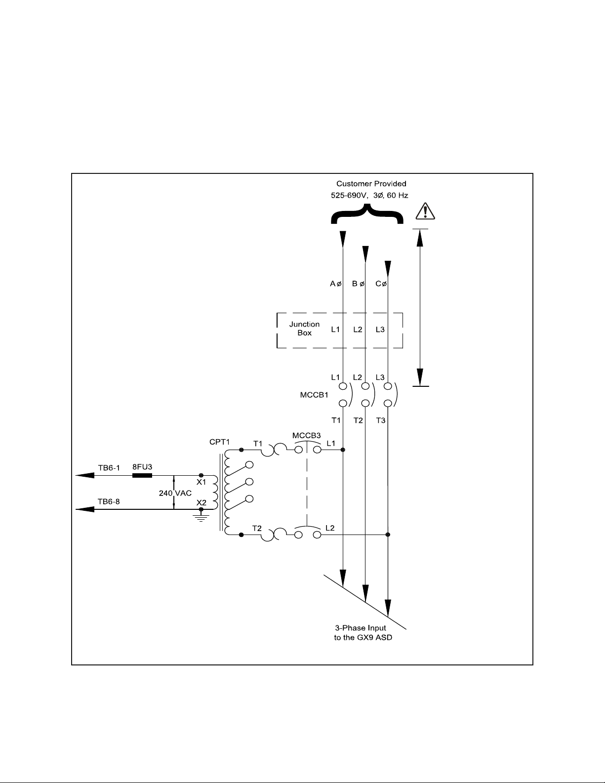
Residual Voltage Wa rning
Always
energized.
Not affected by
MCCB1 switch
position.
MCCB1 effective
at remainder of
system.
Ensure that the
Charge LED is off
before attempting
to service the
ASD system.
DANGER
Three-phase input power is applied at all times.
Ensure that the 3-phase power to the system is off and that the system is locked out and tagged out
before per forming maintenance or repair on the GX9 ASD system.
The relationship of MCCB1 to the total system is shown in Figure 1.
Figure 1. Placement of the MCCB1 circuit breaker in the GX9 ASD system.
GX9 ASD Installation and Operation Manual 7
System Integration Precautions
WARNING
The following precautions are provided as general guidelines for the setup of the ASD within the
system.
• The ASD is a general-purpose pro duct. It is a s ystem compo nent on ly and the system design should
take this into consideration. Please contact the Toshiba Customer Support Center for applicationspecific information or for training support.
• The ASD is part of a larger system and the safe operation of the ASD will depend upon observing
certain precautions and performing proper system integration.
• Improperly designed or imp rop erly in stalled sy stem in terlocks may r ender the motor u nable to st art
or stop on com mand.
• The failure of external or ancillary components may cause intermittent system operation (i.e., the
system may start the motor without warning).
• A detailed system analysis and job safety analysis shall be performed by the systems designer and/
or systems integrator before the installation of the ASD component. Contact the Toshiba Customer
Support Center for options availability and for application-specific system integration information
if required.
Personnel Protection
• Installation, operation, and maintenance shall be performed by Qualified Personnel ONLY.
• A thorough understanding of the ASD will be required before the installation, operation, or
maintenance of the ASD.
• Rotating machinery and live conductors can be hazardous and shall not come into contact with
personnel. Personnel shall be protected from all rotating machinery and electrical hazards at all
times.
• Insulators, machine guards, and electrical safeguards may fail or be defeated by the purposeful or
inadvertent actions of workers. Insulators, machine guards, and electrical safeguards are to be
inspected (and tested where possible) at installation and periodically after installation for potential
hazardous conditions.
• DO NOT allow personnel near rotating machinery. Warning signs to this effect must be clearly
posted at or near the machinery/hazard.
• DO NOT allow personnel near electrical conductors. Contact with electrical conductors can be
fatal. Warning signs to this effect must be clearly posted at or near the machinery/hazard.
• Personal Protection Equipment (PPE) shall be provided and used to protect the installer, user,
maintenance personnel, and all employees from any hazards inherent to system operation.
8 GX9 ASD Installation and Operation Ma nual

System Setup Requirements
CAUTION
• When using the ASD as an integral part of a larger system, it is the responsibility of the ASD
installer/maintenance personnel to ensure that there is a fail-safe in place (i.e., an arrangement
designed to switch the system to a safe condition if there is a fault or failure).
• Power factor improvement capacitors or surge absorbers MUST NOT be installed on the three-
phase output of the ASD.
• Use of the built-in system protective features is highly recommended (i.e., Emergency Off,
Overload Protection, etc.).
• The operating controls and system status indicators shall be clearly readable and positioned wh ere
they may be viewed without obstruction.
• Additional warnings and notifications shall be posted at the equipment installation location as
deemed required by Qualified Personnel.
• System safety features shall be employed and designed into the integrated system in a manner such
that system operation, even in the event of system failure, will not cause harm or result in system
damage or injury to personnel (i.e., Emergency Off, Auto-Restart settings, System Interlocks, etc.).
• The programming setup and system configuration of the ASD may allow it to start the motor
unexpectedly. A familiarity with the Auto-Restart and Retry settings is a requirement to use this
product.
• The setup procedures included within this manual may require a Reset before performing the
procedure. Application-specific settings may then be performed. The pre-Reset conditions may be
saved (see F007).
• There may be thermal or physical prope rties, or ancillary devices integ rated into the overall system
that may allow for the ASD to start the motor without warning. Warning signs to this effect must be
clearly posted at or near the machinery/hazard.
• If a secondary magnetic contactor (MC) or an AS D output discon nect is used between t he ASD and
the load, it should be interlocked to halt the ASD before the secondary contact opens. If the output
contactor is used for bypass operation, it must be interlocked such that commercial power is never
applied to the ASD output terminals (U, V, or W).
• When using an ASD output disconnect, the ASD and the motor must be stopped before the
disconnect is either opened or closed. Closing the output disco nnect while t he 3- phase o utput of the
ASD is active may result in equipment damage or injury to personnel.
GX9 ASD Installation and Operation Manual 9

Operational and Maintenance
DANGER
Precautions
• Turn off and lock-out/tag-out the main power, the control power, and instrumentation connections
before inspecting or servicing the ASD, removing any enclosure panels, or connecting/
disconnecting the power wiring to the equipment.
• Turn the power on only after attaching (or closing) the front cover. DO NOT open or remove the
front cover or any of the enclosure panels of the ASD during normal ASD operation.
• During system setup, calibration, testing, or troubleshooting it may be required to access live
circuits. DO NOT leave the system unattended and powered with the door(s) and/or covers
removed.
• If/when taking a live reading is required (eq uipm ent is power ed), it is to be perf ormed by Qualified
Personnel ONLY. Proper and approved personal protection equipment is to be used by trained
personnel for all electrical measurements.
• The capacitors of the ASD maintain a residual charge for a period of time after the ASD is powered
off. The required time for each ASD typeform is indicated with a cabinet label and a Charge
Indicator LED (see Figure 3 on pg. 17). Wait at least the minimum time indicated on the
enclosure-mounted label and ensure that the Charge Indicator LED has turned off once the ASD
power has been turned off before coming into contact with any circuits.
• DO NOT attempt to disassemble, modify, or repair the ASD. Contact the Toshiba Customer
Support Center for repair information.
• DO NOT place any objects inside of the ASD.
• If the ASD should emit smoke, or an unusual odor or sound, turn off the power immediately.
• The heat sink and other com ponents may become extremely hot to the touch. Allow the unit to cool
before coming in contact with these items.
•The Auto-Restart and Retry programmable functions of the ASD may allow for the system to
start or stop unexpectedly. Warning signs to this effect must be clearly posted at or near the
machinery/hazard.
• Remove power from the ASD during extended periods of non-use.
• Inspect the system annually (as a minimum) for damaged or improperly functioning parts,
cleanliness, and to ensure that the connectors are tightened securely. Inspect more frequently when
operating in a harsh environment or when used on a high-output-demand application.
10 GX9 ASD Installation and Operation Manual

Motor Characteristics
Listed below are some variable speed AC motor control concepts with which the user of the
GX9 Adjustable Speed Drive should become familiar.
Motor Autotuning
Motor production methods may cause minor differences in the motor operation. The negative effects of
these differences may be minimized by using the Autotune feature of the GX9 ASD. Autotuning is a
function of the GX9 ASD that measures several parameters of the connected motor and places these
readings in a stored table. The software uses the information in the table to help optimize the response of
the GX9 ASD to application-specific load and operational requirements. The Autotuning function may
be enabled for automatic tuning, configured manually, or disabled (see F400 – F414).
The measured parameters include the rotor resistance, the stator resistance, the required excitation
inductance, rotational inertia values, and leakage inductance values.
The GX9 ASD is also equipped with a factory-loaded table of motor parameters that fit several different
types of mot ors. To use this function, disable Autotune and select a motor type at F413.
Pulse Wid t h Modulation Operation
The GX9 ASD uses a sinusoidal Pulse Width Modulation (PWM) control system. The output current
waveform generated by the GX9 ASD approaches that of a perfect sine wave; however, the output
waveform is slightly distorted. For this reason, the motor may produce more heat, noise, and vibration
when operated by a GX9 ASD, rather than directly from commercial power.
Low Speed Operation
Operating a general-purpose motor at lower speeds may cause a decrease in the cooling ability of the
motor. Reducing the torque requirement of the motor at lower speeds will decrease the generated heat at
lower speeds.
When the motor is to be operated at low speed (less than 50% of full speed) and at the rated torque
continuously, a VF motor (designed for use in conjunction with an ASD) is recommended.
Overload Protection Adjustment
The GX9 ASD software monitors the output current of the system and determines when an overload
condition occurs. The overload current level is a percentage of the rated system current. This function
protects the motor from overload.
The default setting for the overload detection circuit is set t o th e maxi mu m rate d cu rren t of t he GX9 ASD
at the factory . Thi s setti ng will have to be adjusted to match the rating of the motor with which the GX9
ASD is to be used. To change the overload reference level, see Motor Overload Protection Level 1 on pg.
184.
GX9 ASD Installation and Operati on Manual 11

Operation Above 60 Hz
A motor produces more noise and vibration when it is operated at frequencies above 60 Hz. Also, when
operating a motor above 60 Hz, the rated limit of the motor or its bearings may be exceeded; this may void
the motor warranty .
Contact the motor manufacturer for additional information before operating the motor above 60 Hz.
Power Factor Correction
DO NOT connect a power factor correction capacitor or surge absorber to the three-phase output of the
GX9 ASD.
If the GX9 ASD is used with a motor that is equipped with a capacitor for power factor correction, remove
the capacitor from the motor.
Connecting either of these devices to the output of the GX9 ASD may cause the GX9 ASD to malfunction
and trip, or the output device may cause an over-cur rent condition resulting in damage to the device or the
GX9 ASD.
Light Load Conditions
When a motor is operated under a continuous light load (i.e., at a load of less than 50% of its rated
capacity) or it drives a load which produces a very small amount of inertia, it may become unstable and
produce abnormal vibration or trips because of an over-current condition. In such a case, the carrier
frequency may be lowered to compensate for this undesirable condition (see Program Special
Carrier Frequency).
Note: For proper operation, the carrier frequency must be 2.2 kHz or above except when
operating in the Constant Torque, Variable Torque, or the 5-Point Setting modes.
Note: See F300 for more information on setting the carrier frequency for normal operation
and for setting the carrier frequency above the derate threshold.
Motor/Load Combinations
When the GX9 ASD is used in combination with one of the following motors or loads, it may result in
unstable op eration.
• A motor with a rated capacity that exceeds the motor capacity recommended for the GX9 ASD.
• An explosion-proof motor.
When using the GX9 ASD with an explosion-proof motor or other special motor types, lower the carrier
frequency to stabilize the operation. DO NOT set the carrier frequency below 2.2 kHz if operating the
system in the vector control mode.
Note: For proper operation, the carrier frequency must be 2.2 kHz or above except when
operating in the Constant Torque, Variable Torque, or the 5-Point Setting modes.
• If the motor is coupled to a load that has a large backlash or a reciprocating load, use one of the
following procedures to stabilize its operation.
• Adjust the S-pattern acceleration/deceleration setting,
• If in the Vector control mode, adjust the response time, or
•Switch to the Constant Torque control mode.
12 GX9 ASD Installation and Operation Manual

Load-Produced Negative Torque
CAUTION
When the GX9 ASD is used with a load that produces negative torque (an overhauling load), the overvoltage or over-current protective functions of the GX9 ASD may cause nuisance tripping.
To minimize the undesirable effects of negative torque the dynamic braking system may be used if so
equipped. The dynamic braki ng sys tem conver ts the regenerated ener gy into heat that is dissipa ted using a
braking resistor. The braking resi stor must be suitably matched to the load. Dynamic braking is also
effective in reducing the DC bus voltage during a momentary over-voltage condition.
If under extreme conditions the dynamic braking system or a component of this system were to fail, the
dynamic braking resistor may experience an extended over-current condition. The DBR circuit was
designed to dissipate excessive amounts of heat and if the extended over-current condition were allowed
to exceed the circuit parameters, this condition could result in a fire hazard.
T o combat this condition, the 3- phase input ma y be connected using contactor s that are configured to open
in the event of an extended DBR over-current condition or an internal circuit failure. Using a thermal
sensor and/or overload protectio n as the 3-phase i nput con tactor d rive sig nal, the co ntactors will open and
remove the 3-phase input power in the event of an extended DBR over-current or system over-voltage
condition.
Motor Braking
The motor may continue to r otate and coas t to a stop afte r being shut of f due to the i nertia of the load. If an
immediate stop is required, a braking system should be used. The two most common types of motor
braking systems used with the GX9 ASD are DC Injection Braking and Dynamic Brakin g.
For further information on braking systems, see DC Injection Braking on pg. 124 and Dynamic Braking
on pg. 132.
GX9 ASD Installation and Operati on Manual 13

GX9 ASD Characteristics
CAUTION
Over-Current Protection
Each GX9 ASD model is designed for a specified operating power range. The GX9 ASD will incur a trip
if the design specifications are exceeded.
However, the GX9 ASD may be operated at 1 10% of the specified output-cur rent range continuo usly. The
5.0 HP – 125 HP can operate at 150% for 60 seconds. The 150 HP – 1200 HP may be operated at 130%
for 120 seconds as indicated in the section titled Voltage/Current Specifications on pg. 237. Also, the Stall
Prevention Level (see F601) may be adjusted to help with nuisance over-current trips.
When using the GX9 ASD for an application that controls a motor which is rated significantly less than
the maximum current rating of the GX9 ASD, the over-current limit setting will have to be changed to
match the application. See Motor Overload Protection Level 1 for further i nfor mati on on this ASD/motor
configuration.
GX9 ASD Capacity
The GX9 ASD must not be used with a motor that has a significantly larger capacity, even if the motor is
operated under a small load. A GX9 ASD b eing us ed in t his way will be su sceptib le to a high-outpu t peak
current which may result in nuisance tripping.
Do not apply a level of input v olta ge to a GX 9 ASD that is b eyo nd t hat wh ich t he GX9 AS D is rat ed. The
input voltage may be stepped down when required with the use of a step-down transformer or some other
type of voltage reduction system.
Using Vector Control
Using Vector Control enables the system to produce very high torque over the entire operating range
even at extremely low speeds. Vector Control may be used with or without feedback. However, using
feedback increases the speed accuracy for applications requiring precise speed control. Enabling the
Automatic Energy Savings further increases the efficiency of the GX9 ASD while maintaining its robust
performance.
Vector Control is not capable of operating multiple motors connected in parallel.
See V/f Pattern on pg. 80 for further information on using Vector Control.
Local/Remote Operation
While running in the Local mode at a non-zero speed, if the RJ45 connector is removed from the EOI, the
GX9 ASD remains in the Local mode running at the last commanded speed even though the Local LED
is off. The GX9 ASD output remains at the fr equency of the Fr equency Command field at the time of the
disconnect for the duration of the disconnect.
To prevent this condition, before disconnecting the RJ45 connector, ensure that the GX9 ASD is off.
14 GX9 ASD Installation and Operation Manual

Installation and Connections
CAUTION
The GX9 ASD may be set up initially by performing a few simple configuration settings. To operate
properly , the ASD must be securely mounted and co nnected to a power source (3-phase AC input at the
L1/R, L2/S, and L3/T terminals). The control terminals of the ASD may be used by connecting the
terminals of the Terminal Board (P/N 48570) to the proper sensors or signal input sources (see the
section titled I/O and Control on pg. 20 and Figure 6 on pg 24).
Note: The optional A SD-Multicom boards may be used to expand the I/O functionality of
the ASD. See the section titled GX9 ASD Optional Devices on pg. 245 for more
information on the available options.
The output terminals of the ASD (T1/U, T2/V, and T3/W) must be connected to the motor that is to be
controlled (see Figure 19 on pg 30).
As a minimum, the installation of the ASD shall conform to Article 110 of the NEC, the Occupational
Safety and Health Administration requirements, and to any other local and regional industry codes
and standards.
The S tartup W izard assists with the initial configuration of the commonly used GX9 ASD parameters.
See the section titled Startup Wizard on pg. 60 for additional information on the Startup Wizard. The
Startup Wizard is launched by configuring the system to start the wizard automatically upon a system
restart.
Installation Notes
Do Not apply commercial power to the output terminals T1/U, T2/V, or T3/W.
If an output contactor is used for bypass operation, it must be interlocked such that commercial power is
never applied to the output terminals of the ASD (T1/U, T2/V, or T3/W).
If a secondary magnetic contactor ( MC) is u sed betw een the ou t put o f th e A SD and the mo t or, it should
be interlocked such that the ST – CC connection is disconnected before the output contactor is opened.
Do Not open and then close a secondary magn etic c ontactor between the ASD and the mo tor unles s the
ASD is off and the motor is not rotating.
Note: Re-application of power via a secondary contact while the ASD is on or while the
motor is still turning may cause ASD damage.
Disconnect the ASD from the motor before megging or applying a bypass voltage to the motor.
When a brake-equipped motor is connected to the ASD, it is possible that the brake may not release at
startup because of insufficient voltage. To avoid this, Do Not connect the brake or the brake contactor to
the output of the ASD.
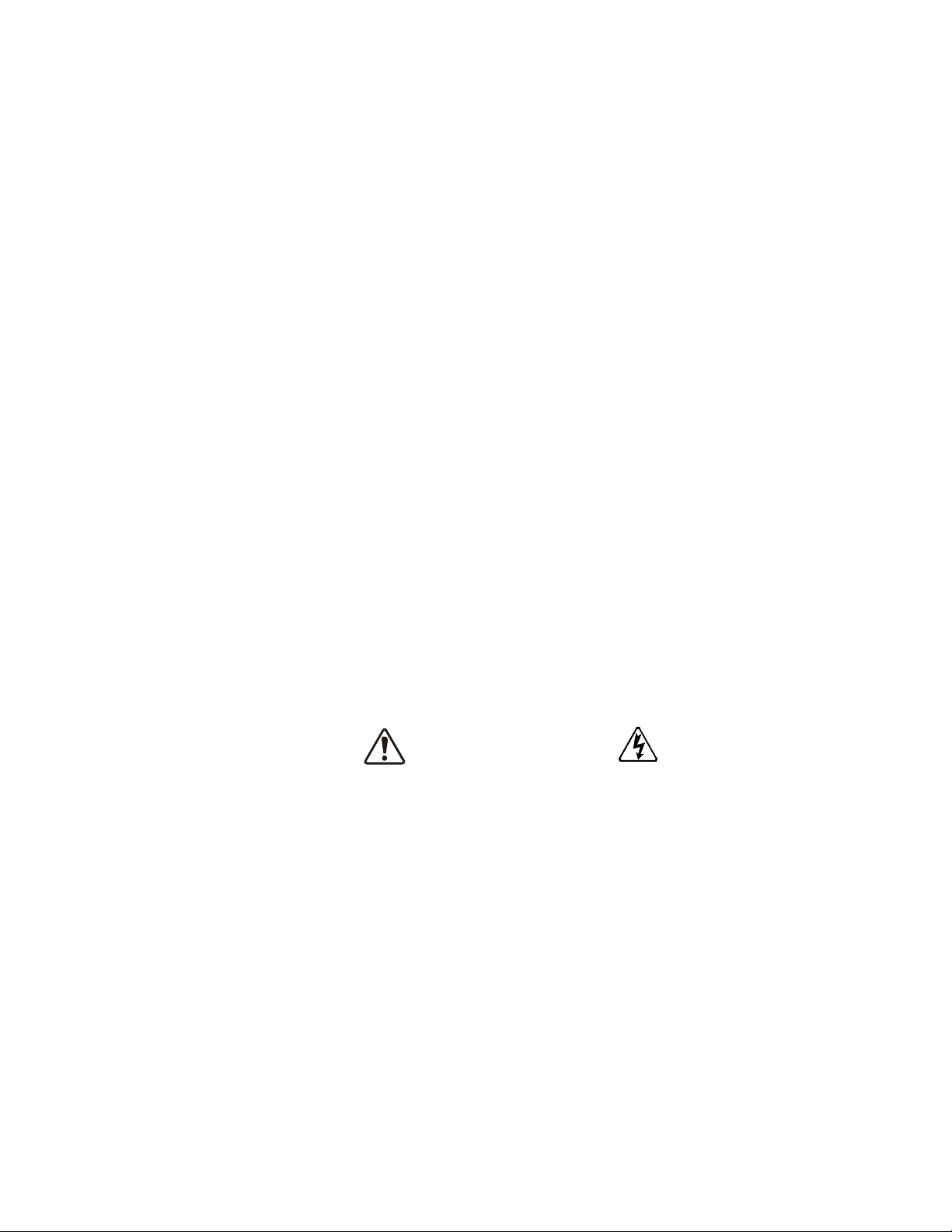
The ST-to-CC connection is further enhanced by the operation of the MS1 AUX relay circuit. The MS1
AUX relay circuit is normally open and closes the ST-to-CC connection (via ST1) only after normal
system power is available. The MS1 AUX relay circuit prohibits the ST-to-CC connection in the event
that the MS1 contactor fails to close during start up or if MS1 opens while the ASD is running.
GX9 ASD Installation and Operation Manual 15
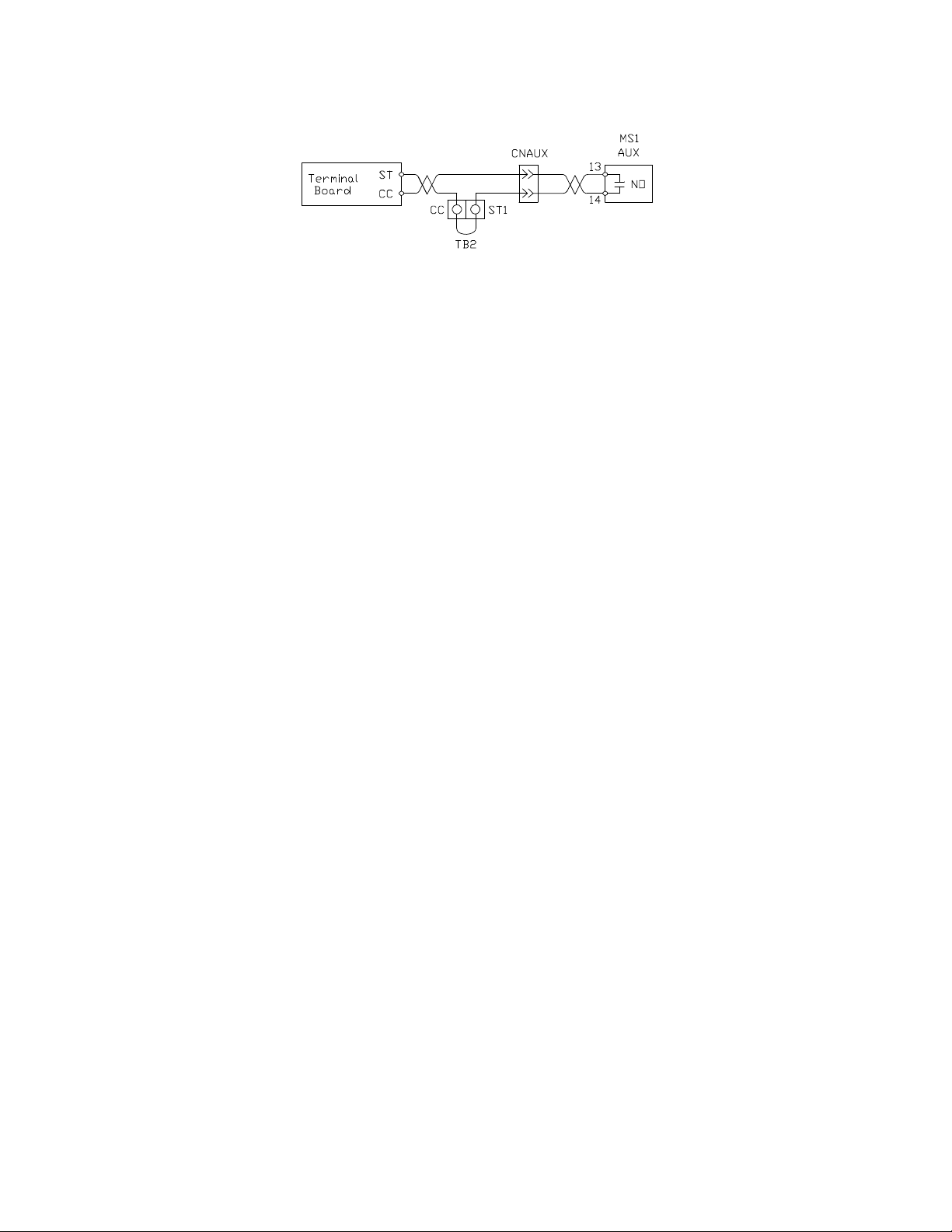
Figure 2. ST activation using the MS1 AUX circuit configuration.
CAUTION
The ASD input voltage should remain within 10% of the specified input voltage range. Input voltages
approaching the upper or lower limit settings may require that the over-voltage and under-voltage stall
protection level parameters, F626 and F629, be adjusted. Voltages outside of the permissible tolerance
should be avoided.
The freque ncy of the input power should be ±2 Hz of the specified input frequency.
Do not use an ASD with a motor that h as a po wer r ating that is greater than the rated output of the ASD.
The ASD is designed to operate NEMA B motors. Consult with the Toshiba Customer Support Center
before using the ASD for special applications such as with an explosion-proof motor or applica tions
with a piston load.
Interface problems may occur when an ASD is used in conjunction with some types of process
controllers. Signal isolation may be required to prevent controller and/or ASD malfunction (contact the
Toshiba Customer Support Center or the process controller manufacturer for additional information
about compatibility and signal isolation).
Use caution when setting the output frequency. Over speeding a motor decreases its ability to deliver
torque and may result in damage to the motor and/or the driven equipment.
Mounting the ASD
Install the unit securely to the floor or a wall in a well ventilated area that is out of direct sunlight.
The ambient temperature rating for the GX9 ASD is from 14° to 104° F (-10° to 40° C).
The process of converting AC to DC, and then back to AC produces heat. During normal ASD
operation, up to 5% of the input ener gy to th e ASD may b e dissipated as heat. I f inst alling the ASD in a
cabinet, ensure that there is adequate ventilation.
During system setup, calibration, testing, or troubleshooting it may be required to access live circuits.
DO NOT leave the system unattended and powered with the door(s) and/or covers removed.
When perfor ming maintenance DO NOT insert fingers into the holes of the enclosure.
Note: Ensure that the ventilation openings are not obstructed.
ASDs produce high-frequency noise — steps must be taken during installation to avoid the negative
effects of noise. Listed below are some examples of measures that will help to combat noise problems.
• Separate the input and output power conductors of the main circuit. Do not install the input and
output wires in the same duct or in parallel with each other, and do not bind them together.
• Do not install the input or output power conductors of the main circuit and the wires of the control
circuit in the same duct or in parallel with each other, and do not bind them together.
• Use shielded wires or twisted wires for the control circuits.
• Ensure that the grounding terminals (G/E) of the ASD are securely connected to ground.
• Connect a surge suppressor to electromagnetic contactors and relays installed near the ASD.
• Install noise filters as required.
16 GX9 ASD Installation and Operation Manual
Connecting the ASD
DANGER
Charge LED
Contact With 3-Phase Input/Outp ut Terminals May Cause An Electrical Shock
Resulting In Injury Or Loss Of Life.
Refer to the section titled Installation Precautions on pg. 4 and the section titled Lead Length
Specificati ons on pg. 19 before attempting to connect the ASD and the motor to electrical power.
Power Connections
See Figure 19 on pg 30 for a system I/O connectivity schematic.
R/L1, S/L2, and T/L3 are the 3-phase input supply terminals for the ASD.
U/T1, V/T2, and W/T3 are the output terminals of the ASD that connect to the motor.
Connect the input and output power lines of the ASD as shown in Figure 4 on pg 18.
An inductor (DCL) may be connected across the PO and PA/+ terminals to provide additional filtering.
When not used, a jumper must be connected across these terminals.
PA/+ and PB are used for the DBR connection if using a braking resistor.
PC/- is the negative terminal of the DC bus.
The Charge Indicator LED provides an indication that there is a harmful voltage level present. The
location of the Charge Indicator LED is shown in Figure 3.
Ensure that the Charge Indicator LED is off before coming into contact with any circuits or attempting
to perform any maintenance on the ASD.
Note: The GX9610K is shown in figure 3 below. See the drawings of the system received for
the actual location of the Charge LED.
Figure 3. Typical GX9 ASD Charge Indicator LED.
GX9 ASD Installation and Operation Manual 17
Power Connection Requirements
CAUTION
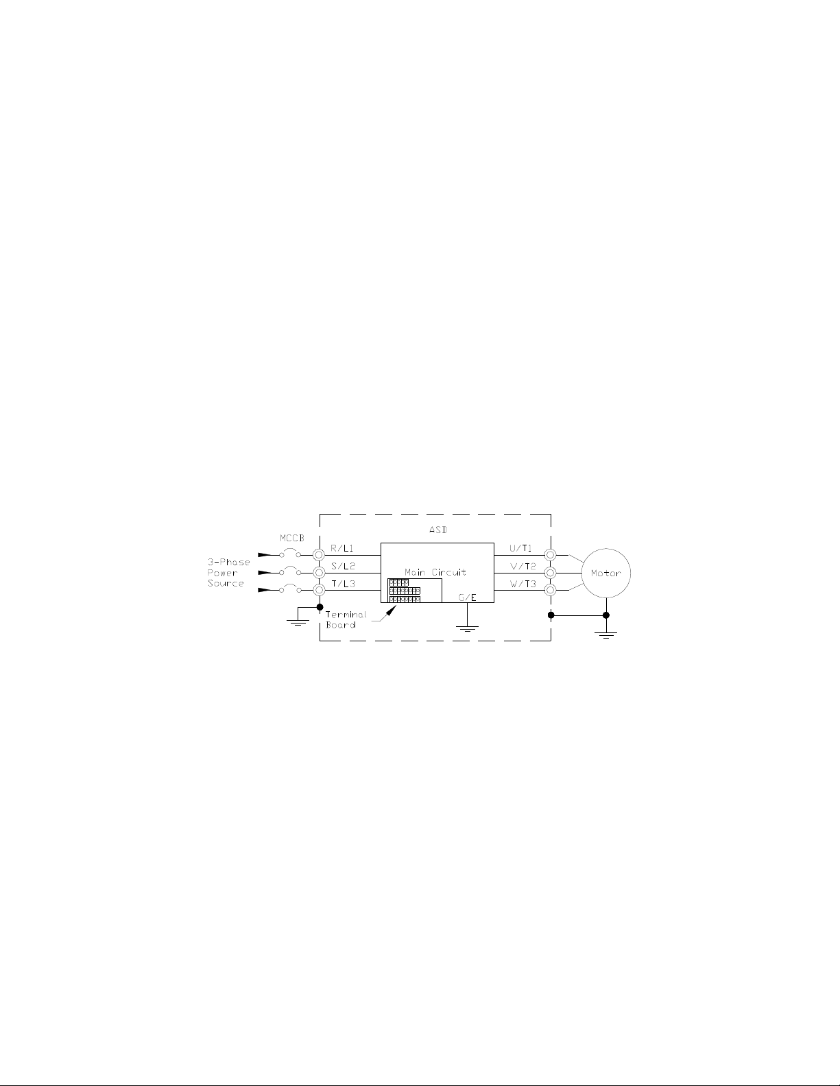
Connect the 3-phase in put power o f the co rrect voltage to t he input terminal s of the AS D at R/L1, S/L2,
and T/L3 (see Figure 4 for the typical electrical connection scheme and on pg 19 for the terminal
locations).
Connect the output of the ASD to the m otor fr om the ASD terminals U/T1, V/T2, and W/T3. The input
and output conductors and terminal lugs used shall be in accordance with the requirements listed in the
section titled Voltage/Current Specifications on pg. 237.
Install a molded case circuit breaker (MCCB) or fuse between the 3-phase power source and the ASD in
accordance with the fault current setting of the ASD and the NEC Article 430.
The ASD is designed and tested to comply with UL Standard 508C. Modifications to the ASD system
may disqualify the UL rating.
As a minimum, the installation of the ASD shall conform to the NEC Article 110, the Occupational
Safety and Health Administration requirements, and to any other local and regional industry codes
and standards.
Note: In the event that the motor rotates in the wrong direction when powered up, reverse
any two of the three AS D output power leads (U, V, or W) connected to the motor.
Figure 4. The GX9 ASD/Motor Typical Connection Diagram.
18 GX9 ASD Installation and Operation Manual
 Loading...