

Toshiba GRZ100-500, GRZ100-200, GRZ100-211B, GRZ100-214B, GRZ100-216B User Manual
...

GRZ100
2
FEATURES
Fully numerical distance protection relay
High speed operation typically 20ms
Time-stepped distance protection with four forward
zones, two reverse zones, and one non-directional
zone
Zone 1 extension protection
Command protection distance schemes (PUP, POP,
BOP and UOP with week infeed and current reversal
logic)
Command protection DEF schemes (POP, BOP and
UOP)
Single- and/or three-phase trip
High-resistance earth fault protection
Overcurrent backup protection
Thermal overload protection
Overvoltage and undervoltage protection
Switch-on-to-fault (SOTF) and stub protection
Broken conductor detection
Breaker failure protection
Out-of-step trip protection
Power swing blocking
VT failure detection
Single-shot (single/three/single+three phase) or
multi-shot (three phase) autoreclose
Fault location
Configurable binary inputs and outputs
Programmable logic for I/O configuration, alarms,
indications, recording, etc.
Automatic supervision
Metering and recording functions
Menu-driven user interfaces
Front-mounted RS232C port for communication to a
local PC and rear-mounted RS485, Fibre optic or
Ethernet LAN serial ports for communication to a
remote PC
IRIG-B port for external clock
The IEC60870-5-103 protocol is provided for
communication with substation control and
automation systems.
GRZ100 can be provided with integral digital communication channels for teleprotection signalling. Either one or
two communication channels are provided, suitable for
relay-to-relay connection via fibre-optic links, or via
electrical interfaces to a digital communication network.
GRZ100 can be configured using the integral communication channels to support the following functions:
Phase-segregated command protection distance
schemes (PUP, POP, BOP and UOP with week
infeed and current reversal logic).
Phase-segregated command protection DEF
schemes (POP, BOP and UOP).
Command protection signalling for tripping during a
power swing.
Command protection for 2- or 3-terminal applications.
Phase-segregated transfer trip (intertripping).
Transmission of binary signals for user-configurable
applications.
Transmission of measured values to be displayed at
the remote terminals.
Synchronisation of the clocks at the various terminals.
Enhanced fault-location accuracy by use of remote- end
data in the case of 3-terminal applications.
Continuous monitoring of the communication channels,
with capability to provide dual-redundant channels in
the case of a 2-ended system, and automatic
re-routing of signals in the event of a communication channel failure in a 3-ended system.
APPLICATION
GRZ100 is a full-scheme high-speed numerical distance
relay for application to transmission lines in solidly earthed
networks.
GRZ100 provides the following protection schemes.
Time-stepped distance protection
Zone 1 extension protection
Command protection (distance protection using
telecommunication)
Overcurrent protection for SOTF and stub fault
Out-of-step trip protection
Breaker failure protection
As a backup protection for high-resistance earth faults,
GRZ100 provides the following four functions.
Directional earth fault protection
Directional earth fault protection using
telecommunication
Directional or non-directional inverse time overcurrent
and earth fault protection
Definite time overcurrent and earth fault protection
GRZ100 can initiate high-speed single-shot autoreclose or
multi-shot autoreclose.
GRZ100 provides the following metering and recording
functions.
Metering
Fault recording
Event recording
Disturbance recording
GRZ100 provides the following user interfaces for relay
setting or viewing of stored data.
Relay front panel; LCD, LED display and operation keys
Local PC
Remote PC
GRZ100
3
A local PC can be connected to the relay via the RS232C
port on the front fascia of the relay. Either one or two rear
ports (RS485 or fibre optic) are provided for connection to a
remote PC and for IEC60870-5-103 communication with a
substation control and automation system. Further, an
Ethernet LAN port (TCP/IP) can be provided.
GRZ100 has four models which differ depending on
whether or not the autoreclose or fault detector
provided
with independent MPU and trip contact for fail-safe
function
have been included.
Model 200
series
- With autoreclose for single
breaker scheme
Model 300
series
- With autoreclose for one-and-ahalf breaker scheme
Model 400
series
- With autoreclose for single
breaker scheme
- With fault detector
Model 500
series
- With autoreclose for one-and-ahalf breaker scheme
-With fault detector
The following GRZ100 models provide integral digital
communication channels for protection signalling. These
models can also be applied using standard, external
teleprotection equipment.
Model
211B,
214B,
216B
- 2-terminal line application
(one communication channel)
- With autoreclose for single breaker
scheme
Model
311B
- 2-terminal line application
(one communication channel)
- With autoreclose for
one-and-a-half breaker scheme
Model
221B,
224B,
226B
- 2- / 3-terminal line application
(two communication channels)
- With autoreclose for single breaker
scheme
Model
321B,
323B
- 2- / 3-terminal line application
(two communication channels)
- With autoreclose for
one-and-a-half breaker scheme
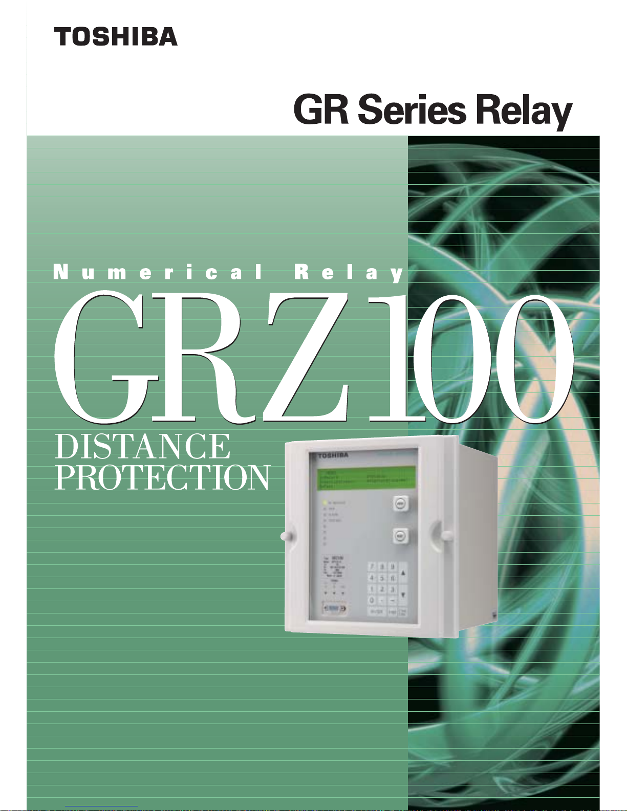
In the GRZ100 models provided with an integral digital
communication channel for protection signaling, four
communication topologies are available depending on the
model. Models 211/214/216/311B support configuration (a)
only in Figure 1. Models 221/224/226/321/323B can support
all configurations. Configuration (b) and (d) offer security
against failure of a communication link.
RELAY B RELA Y A
Ch1 Ch1
(a) Two-ended system, single channel
RELAY B RELAY A
Ch1 Ch1
Ch2 Ch2
(b) Two-ended system, dual redundant channels
RELAY A
RELAY B RELAY C
Ch1
Ch1
Ch1
Ch2
Ch2
Ch2
(c) Three-ended system, chain topology
RELA Y A
RELAY B RELA Y C
Ch1
Ch1
Ch1
Ch2
Ch2
Ch2
(d) Three-ended system, ring topology
Figure 1 Communication System Topologies
RELAY FUNCTIONS
Time-Stepped Distance Protection
GRZ100 provides maximum four-zone distance protection
(Z1, Z2, Z3, ZF) for forward faults, two-zone distance
protection (ZR1, ZR2) for reverse faults and one nondirectional distance protection (ZND) for both forward and
reverse faults.
GRZ100 provides individual phase-fault measuring elements
and earth-fault measuring elements for all types of fault.
Direction measurement in GRZ100 is based on cross
polarization with voltage memory to ensure dependable
fault detection. GRZ100 uses an advanced distance
measurement algorithm which achieves accurate fault
impedance measurement over a wide range of frequencies.
This superior algorithm also minimizes the effect of CT
saturation and gives stable performance with CVT
transients.
The GRZ100 provides measuring zones with mho-based
characteristics or quadrilateral characteristics, as shown in
Figures 2 and 3.
As shown in Figure 2, mho-based characteristics are
composed of mho element, offset mho element, reactance
element, and blinder element for phase fault protection and
earth fault protection.

GRZ100
4
(a) Phase fault measuring element
(b) Earth fault measuring element
Figure 2 Mho-based Characteristics
As shown in Figure 3, quadrilateral characteristics are
composed of reactance element, directional element and
blinder element. Reverse zones for phase fault use the
offset directional element to ensure reverse close-up fault
detection.
Z1 is applied to Zone 1 protection. The reactance line of Z1
can be configured to take a negative gradient when the
terminal is sending power, which prevents Z1 from
overreaching for remote end faults.
To ensure that GRZ100 can provide reliable time-delayed
tripping for close-up three-phase faults, the phase fault
elements are reverse offset following Z1 operation.
Z2 is applied to Zone 2 which provides protection for the
rest of the protected line not covered by Zone1 and backup
protection for the remote end busbar.
Z3 is applied to Zone 3 which provides remote back-up
protection for adjacent lines. Z3 is also used for detection of
forward faults in command protection. If Z3 is dedicated to
command protection, then ZF can be used for Zone 3
instead of Z3 in time-stepped distance protection.
(a) Phase fault measuring element
(b) Earth fault measuring element
Figure 3 Quadrilateral Characteristics
ZR1 and ZR2 are reverse looking elements applied to
Reverse Zone 1 and Zone 2, and used for local back-up
protection for busbar faults or transformer faults.
Z4 is used for detection of reverse faults in command
protection.
Z4S has an offset characteristic in order to assure detection
of close-up phase faults.
Zone 1 Extension
When telecommunications cannot be applied, a Zone 1
extension (Z1X) protection is provided for high-speed
protection of any fault along the whole length of the
protected line.
The reactance line of Zone 1 extension can take a negative
gradient when the terminal is sending loads, which prevents
Zone 1 extension from overreaching.
Command protection
The following four schemes are available for distance
protection using telecommunication.

GRZ100
5
- Permissive Underreach Protection (PUP)
- Permissive Overreach Protection (POP)
- Unblocking Overreach Protection (UOP)
- Blocking Overreach Protection (BOP)
POP and UOP are equipped with echo logic and weak
infeed tripping functions and can be used in the protection of
lines with weak infeed or no infeed terminals. An
undervoltage element is incorporated for the weak infeed
tripping function.
Earth Return and Mutual Coupling
Compensation
Z1G, Z2G, Z1XG and ZR1G for earth fault protection adopt
vectorial zero sequence current compensation to eliminate
distance measuring errors due to the earth return of zero
sequence current. When the GRZ100 is applied to a double
circuit line, in order to eliminate the influences of zero
sequence mutual coupling, the zero sequence current for
the parallel line can be introduced. ZR1G is not provided
with zero sequence mutual coupling compensation for the
parallel line.
Application to long and short lines
The large capacitance of a long transmission line can
adversely affect the measurement of fault impedance. GRZ100
employs an advanced charging current compensation technique
which gives significant improvement in impedance
measurement for long transmission lines.
The suitability of a distance relay for application to short
lines is not determined by its minimum setting but rather by
its measuring accuracy for high SIR conditions. GRZ100
provides highly accurate measuring elements suitable to be
applied to short lines.
Fault Phase Selection
GRZ100 provides single- and/or three-phase tripping
functions.
In order to perform extremely reliable single-phase tripping, an
undervoltage element with current compensation is used for
fault phase selection.
The undervoltage element with current compensation can
operate correctly even for a fault with a strong power source
and small voltage drop at the relay installation point.
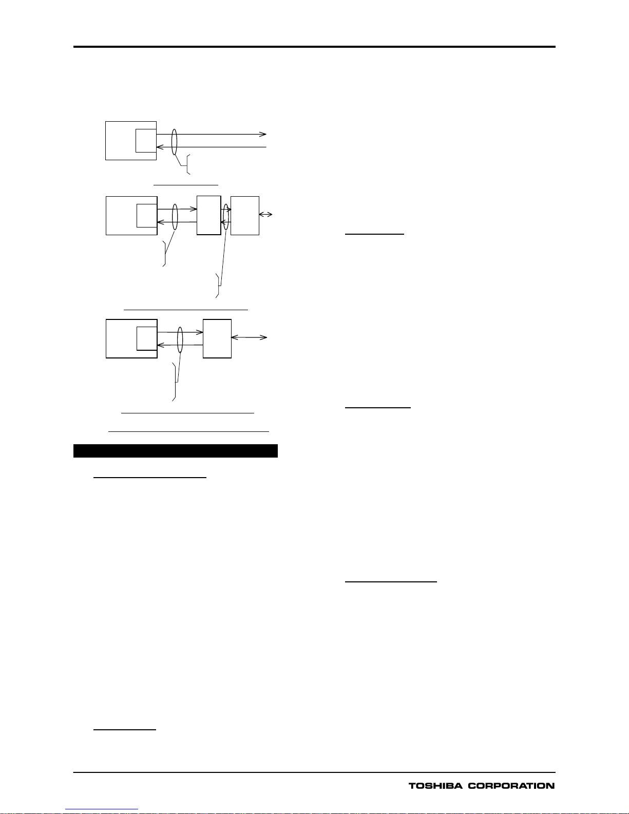
The characteristics of the phase selection element are as
shown in Figure 4.
V
IZc
I
Vk
I: Fault current
Vk: Undervoltage setting
Zc: Im
p
edance setting
V: Fault volta
g
e
Figure 4 Phase selection element
Switch-on-to-fault Protection and Stub
Protection
Switch-on-to-fault (SOTF) protection is provided in order to
detect faults that are present when a line or busbar is
energized.
For 500 ms following circuit breaker closure, this function is
effective to protect against any switch-on-to-fault. A
non-directional overcurrent element or distance measuring
elements perform the SOTF protection.
Stub protection operates for a fault in a stub zone using an
overcurrent element.
Voltage Transformer Failure Supervision
Failure in the voltage transformer (VT) secondary circuit
may cause false tripping by voltage dependent measuring
elements. Therefore, the following voltage dependent
protections are blocked instantaneously when VT failure is
detected.
- Distance protection
- Directional earth fault protection
- Protection using telecommunications
- Out of step protection
VT failure is detected in any of the following cases.
- If residual voltage is detected when residual current is not
detected.
- If undervoltage is detected when a current change is not
detected.
Power Swing Blocking
The relay provides a power swing blocking (PSB) function to
prevent false tripping by distance measuring elements
during a power swing.
When a power swing is detected, all distance protection
zones and protection using telecommunications can be
blocked independently. The non-directional zone, ZND, is
not blocked.
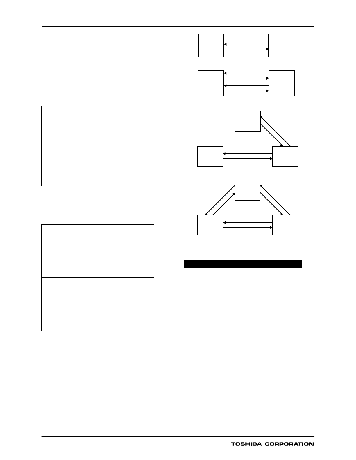
A power swing condition is detected using two PSB
elements with quadrilateral characteristics shown in Figure 5.
The outer PSB element PSBOUT encloses the inner
element PSBIN, the two elements being separated by a
width of PSBZ. Further, GRZ100 provides PSBSZ and
PSBGZ for phase fault measuring elements and earth fault
measuring elements respectively. Their functions and
characteristics are identical. PSBGZ provides
phase-segregated characteristics.
If the impedance locus enters the PSBZ zone for more than
a predetermined time (20 to 60ms), the PSB function will
block the selected zones. The PSB function is reset after
500 ms when the impedance locus has moved outside the
PSB elements.
GRZ100 can provide high speed tripping for faults which
occur during a power swing condition, by utilising a
well-proven, dedicated negative sequence directional
element and any of the PUP, POP, UOP and BOP
command schemes.
GRZ100
6
PSBZ
PSBZ PSBZ
0
PSBZ
PSBIN
PSBOUT
R
X
PSBZ: Impedance setting of PSB element
Figure 5 Characteristics of power swing blocking element
Out-of-step Trip Protection
The out-of-step tripping function is used to execute power
system separation at the optimum point when an out-of-step
occurs.
An out-of-step is detected by using two distance measuring
elements with quadrilateral characteristics as shown in
Figure 5. The element operates when the out-of-step locus
passes from Zone A Æ Zone B Æ Zone C (or Zone C Æ
Zone B Æ Zone A) and remains in Zones A and C for the
detection time (TOST).
X
Impedance
locus
OSTX
F
Zone A
OSTR
2
OSTR1
OSTXB
Zone B
Zone C
R
Figure 6 Characteristics of out of step trip element
Breaker Failure Protection
When an overcurrent element remains in operation longer
than a pre-determined length of time following the output of
a trip signal the associated circuit breaker is judged to have
failed and adjacent circuit breakers can be tripped as a
back-up measure.
Two independent timers are available, one of which can be
used to control the RETRIP of the original circuit breaker(s). The
second timer is used to control the backtripping of adjacent
circuit breakers.
For high-speed protection, an overcurrent element with
high-speed reset time is used to prevent a spurious re-trip
or backtrip following a successful trip or re-trip action.
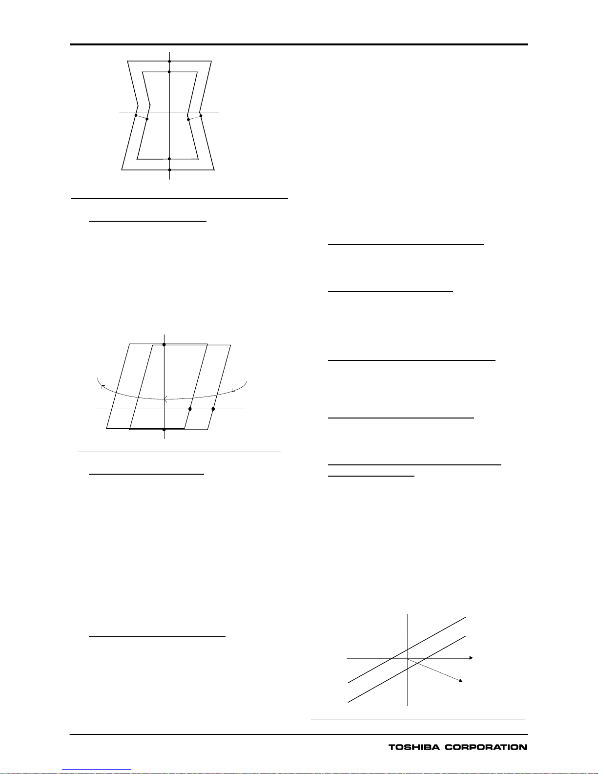
Overcurrent Backup Protection
The IDMT(inverse definite minimum time) overcurrent
element is provided for non-directional inverse time
overcurrent protection. The IDMT element is available in
conformity with either of three IEC Standard characteristics
(Standard inverse, Very inverse, Extremely inverse) or a
Long-time inverse.
The characteristics of each IDMT are shown in Figure 8.
The IDMT element has a reset feature with definite time reset.
If the reset time is set to instantaneous, then no intentional
delay is added. As soon as the energising current falls
below the reset threshold, the element returns to its reset
condition.
If the reset time is set to some value in seconds, then an
intentional delay is added to the reset period. If the
energising current exceeds the setting for a transient period
without causing tripping, then resetting is delayed for a
user-definable period. When the energising current falls
below the reset threshold, the integral state (the point
towards operation that it has travelled) of the timing function
(IDMT) is held for that period.
This does not apply following a trip operation, in which case
resetting is always instantaneous.
Definite time overcurrent protection
Definite time overcurrent protection is enabled by the
instantaneous overcurrent element and pick-up delay timer.
Broken Conductor Detection
The unbalance condition caused by an open circuited
conductor is detected by the broken conductor
detection function. An unbalance threshold with
programmable definite time delay is provided.
High-resistance Earth Fault Protection
This protection provides high-resistance earth fault protection
using the directional earth fault (DEF) element and the earth
fault overcurrent element as follows.
Directional Earth Fault Protection
DEF element is used for time-delayed backup protection for
high-resistance faults.
Directional Earth Fault Protection using
Telecommunication
High-speed DEF protection using telecommunications is
provided by using a forward looking DEF element and a
reverse looking DEF element. POP, UOP, and BOP
schemes can be selected with DEF protection using
telecommunications.
To enable single phase tripping for a high impedance earth
fault, GRZ100, when equipped with the optional integral
communication channels, is provided with phase selection
logic to obtain phase segregated trip permission signals.
The characteristics of the forward and reverse looking DEF
elements are as shown in Figure 7.
-3V
0
Backward DEF
Forward DEF
3I
0
Figure 7 Characteristics of directional earth fault element
GRZ100
7
Inverse Time Overcurrent Earth Fault
Protection
Directional or non-directional inverse time overcurrent earth
fault protection is provided using a combination of the IDMT
(inverse definite minimum time) overcurrent earth fault
element and DEF element. The IDMT element is available
in conformity with either of three IEC Standard
characteristics (Standard inverse, Very inverse, and
Extremely inverse) or a Long-time inverse.
The characteristics of each IDMT are shown in Figure 8.
The IDMT element for earth fault also has a reset feature
with definite time reset.
Figure 8 IDMT operating time characteristics
Definite Time Overcurrent Earth Fault
Protection
Definite time overcurrent earth fault protection is provided
using the instantaneous overcurrent element and pickupdelay timer.
The definite time earth fault (EF) can be configured to issue
either an alarm and/or trip signal.
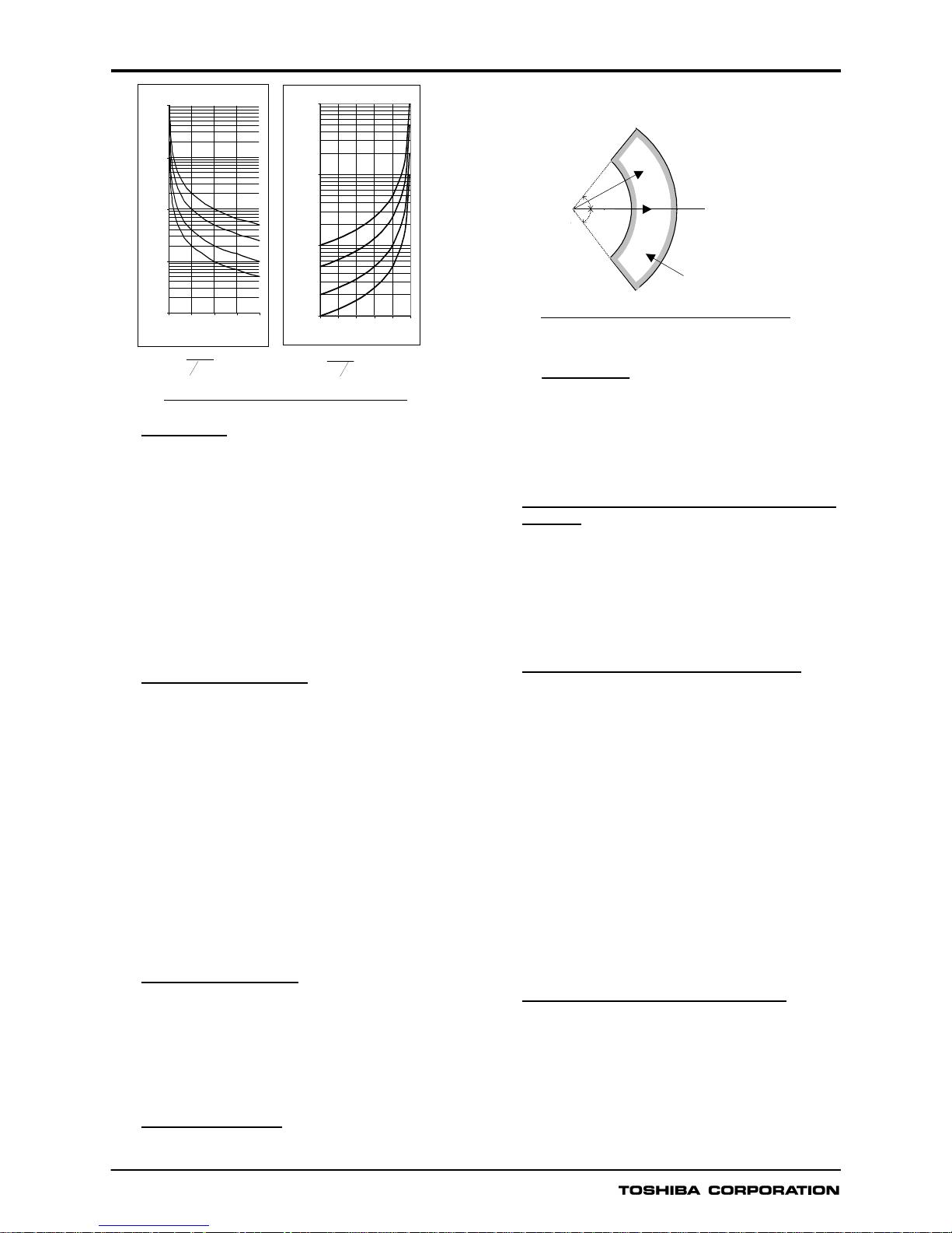
Thermal Overload Protection
The thermal overload feature provides protection for cables
and other plant against the effects of prolonged operation
under excess load conditions. A thermal replica algorithm is
applied to create a model for the thermal characteristics of
the protected plant. Tripping times depend not only on the
level of overload current, but also on the level of prior load
current, the thermal replica providing ‘memory’ of previous
conditions.
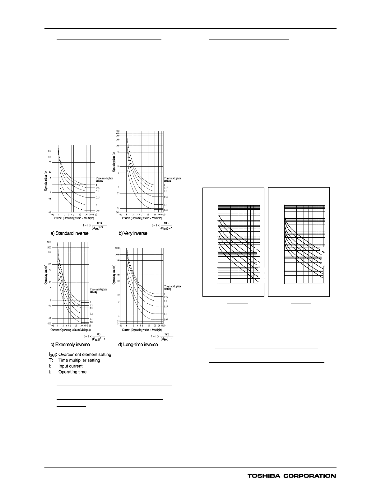
The thermal characteristics of the system are defined by
entering settings for full load current and thermal time
constant. The GRZ100 issues a trip according to the ‘cold’ and
‘hot’ curves specified in IEC60255-8 (see Figure 9), to
prevent the protected system from exceeding its thermal
capacity. The cold curve tripping times are applicable when
the system is first energised, while the hot curves are
relevant when the system has already been carrying some
prior load for a period of time. An alarm output is also
available to give early warning of high load current, set as a
percentage of thermal capacity.
IEC60255-8 Thermal Characteristics
Therm al Curves (Cold Cur ve - no
prior load)
0.01
0.1
1
10
100
1000
110
Overload Current (Multiple of k.I
FLC
)
Operate Time (minutes)
τ
=1
τ
=2
τ
=5
τ
=10
τ
=20
τ
=50
τ
=100
Thermal Curves (Hot Curve - 90%
prior lo ad)
0.001
0.01
0.1
1
10
100
1000
110
Overload Current (Multiple of k.I
FLC
)
Operate Time (minutes)
τ
=100
τ
=50
τ
=20
τ
=10
τ
=5
τ
=2
τ
=1
()
−
=
2
2
2
.
.
FLC
IkI
I
Lnt
τ
;
()
−
−
=
2
2
22
.
.
FLC
P
IkI
II
Lnt
τ
IEC60255-8 ‘Cold’ Curve
IEC60255-8 ‘Hot’ Curve
t = time to trip for constant overload current I (seconds)
I = overload current (largest phase current) (pu)
I
P
= previous load current (pu)
k.I
FLC
(or Iθ) = thermal overload current setting (pu)
τ
= thermal time constant (seconds)
Ln = natural logarithm
Figure 9 IEC60255-8 thermal characteristics
Overvoltage and Undervoltage Protection
GRZ100 provides two-stage overvoltage protections for
both phase-to-phase voltage input and phase-to-neutral
voltage input. The first stage can be set for inverse time or
definite time operation, and the second stage set for definite
time operation. In total, therefore, GRZ100 provides four
independent overvoltage thresholds.
GRZ100 also provides four independent undervoltage
thresholds with two-stage undervoltage protection for
phase-to-phase voltage input and two-stage undervoltage
protection for phase-to-neutral voltage input. The
undervoltage protection is provided with an
undervoltage
blocking function to prevent undervoltage tripping in the
case of a dead line.
GRZ100
8
Overvoltage Inverse Time Curve
s
0.100
1.000
10.00 0
100.000
1000.000
11.5 22.53
Applied Volta ge ( x Vs)
Operating Time (se cs)
TMS = 1
TMS = 2
TMS = 5
TMS = 10
Undervol tage Inver se Time Curv es
1.000
10.000
100.000
1000.000
00.20.40.60.81
Applied Voltage (x Vs)
Operating Time (secs)
TMS = 10
TMS = 5
TMS = 2
TMS = 1
()
xTMS
Vs
V
t
11−
=
()
xTMS
Vs
V
t−=
1
1
Figure 10 Inverse time characteristics
Autoreclose
Most faults on HV and EHV overhead transmission lines are
transient faults, which are removed following line
de-energization. After a short time, the hot gases disperse
and the air de-ionizes. After clearing the fault and deionizing
the fault arc, reclosing can be performed. GRZ100 provides
two autoreclose schemes, single-shot autoreclose and
multi-shot autoreclose.
The GRZ100 autoreclose function can be initiated by any of
the following high-speed protections.
- Protection using telecommunication
- Zone1 extension protection
Single-shot autoreclose
Single-shot reclosing can provide any of three autoreclose modes; single-phase autoreclose, three-phase
autoreclose, and single-and three-phase autoreclose.
In the single-phase autoreclose mode, only a faulted
phase is tripped, and then reclosed if a single-phase
earth fault occurs.
In the three-phase autoreclose mode, all three phases
are tripped, and then reclosed regardless of the fault
mode, whether a single-phase fault or a multi-phase
fault has occurred.
In the single- and three-phase autoreclose mode, the
single-phase is reclosed if a single-phase is tripped and
the three phases are reclosed if three phases are
tripped.
Multi-shot autoreclose
In a multi-shot autoreclose, two- to four-shot reclosing
can be selected. The first shot is selected from any of
the four autoreclose modes available in the single-shot
autoreclose scheme.
If reclosing by the first shot fails, three-phase tripping
and reclosing is applied for the second to fourth shots.
Synchronism Check
For the correct operation of three-phase autoreclose, voltage
and synchronism check are necessary. Characteristics of
the synchronism check element are shown in Figure 11.
VL: Line voltage
V
B
: Busbar voltage
θ: Synchronism
check angle
θ
θ
0 deg
Operating zone
VL
V
B
OV
θ
θ
Figure 11 Synchronism check element
A detected slip cycle is determined by the following equation:
where,
f: slip cycle
θ: synchronism check angle setting
TSYN: synchronism check timer setting
One-and-a-half Breaker Scheme (Models 300
and 500)
GRZ100 performs two-breaker autoreclose in a one-anda-half breaker scheme.
Only single-shot autoreclose is available in Models 300 and
500. Single-phase autoreclose, three-phase autoreclose or
single and three-phase autoreclose can be applied to the
two circuit breakers.
Fault Detector (Models 400 through 500)
For ultra-critical applications, where security is the overriding concern and a two-out-of-two tripping philosophy is
specified, GRZ100 can be provided with an independent
fault detector. This fault detector contains its own main
processing unit (MPU) and trip contacts. The trip contacts
of the main protection are connected in series with the fault
detector trip contacts to ensure completely fail-safe operation.
The fault detector incorporates the following six fault
detection elements.
- Multi-level overcurrent element
- Current change detection element
- Earth fault overcurrent element
- Undervoltage element for earth fault detection
- Undervoltage element for phase fault detection
- Undervoltage change detection element
Interfaces for Integral Communication
GRZ100 can be provided with the following interface(s) and
linked to a dedicated optical fibre communication circuit or
multiplexed communication circuit (multiplexer) shown in
Figure 12.
The electrical interface supports CCITT G703-1.2.1, -1.2.2,
-1.2.3, X.21(RS530) and RS422. Twisted pair cable is used
for connecting the relay and multiplexer. In the case of an
f =
180°ХTSYN
θ
GRZ100
9
optical link via a multiplexer, the optical interface unit G1IF1
(optical to electrical converter) is required for connecting to
the multiplexer. The electrical interface between the
converter and the multiplexer supports CCITT G703 -1.2.1,
-1.2.2, -1.2.3, and X.21(RS530).
b) Optical interface using multiplexer
Multiplexer
Optical
I/F
Unit
G1IF1
GRZ100
Opt.
I/F
CCITT-G703.
ITUT-X.21
Bit rate: 64kbps
GI Opt. Fibre
< 2km
SWL, 64kbps
GRZ100
Elec.
I/F
c) Electrical interface using multiplexer
Multiplexer
Twisted pair wire
CCITT-G703.
ITUT-X.21
RS422
Bit rate: 64kb
p
s
a) Optical interface
GRZ100
Opt.
I/F
Optical Fibre
64kbps
(Option)
Figure 12 Telecommunication system
METERING AND RECORDING
Metering and Monitoring
The following power system data is measured continuously
and can be displayed on the LCD on the relay fascia, at the
local PC, and the remote PC when connected.
- Voltages (phase, phase to phase, symmetrical
components)
- Currents (phase, phase to phase, symmetrical
components)
- Active power and reactive power
- Frequency
Currents and voltages can be indicated as primary or
secondary values. Active power and reactive power are
indicated as primary values.
The user can monitor the following output and status on the
LCD and at local/remote PCs.
- Relay element output
- Binary input/output
- CB status
Event Record
The most recent 480 time-tagged events are stored with
1ms resolution.
The event recorder can be triggered by a Trip signal, by
Overcurrent trigger elements (OC) and by Undervoltage
trigger elements (UV). In case of 'Trip', the trigger is
performed whenever tripping occurs. In case of OC/UV,
On(used) or Off(not used) is selectable.
Event trigger is freely selectable by using PLC.
Events recorded are as follows.
- Tripping and reclosing
- Alarms
- Change of binary input signal
- Change of relay setting
- Relay failure
Fault Record
A relay trip initiates fault recording. Time-tagged fault
data can be stored for the 8 most recent faults. Fault
record items are as follows.
- Date and time
- Faulted phase
- Phases tripped
- Tripping mode
- Fault location
- Pre-fault and post-fault current and voltage data (phase,
phase to phase, symmetrical components)
- Autoreclose operation
Fault Location
Fault location is initiated by relay tripping signals excluding
breaker failure, overcurrent backup and out-of-step tipping. It
can also be started on receipt of a start signal from external
relays.
Fault location is indicated in km and % for the whole length of
the protected line. The fault location is highly accurate for
parallel lines due to the implementation of zero-sequence
mutual impedance compensation.
The result of the fault location is stored as fault record data.
In GRZ100 with integral communication, improved fault
location accuracy is achieved for 3-ended applications by
use of data received from the remote terminals.
Disturbance Record
The relay can record 8 analog and 32 binary signals. The
disturbance recorder is initiated by operation of the overcurrent
element, undervoltage element and/or relay tripping.
In respect to analog data, phase voltage and current,
residual voltage and current, and the residual current of the
parallel line are recorded. The data can be transformed into
the COMTRADE format.
Pre-fault recording time is fixed at 300ms, post-fault
recording time can be set from 100 ms to 3 s. The maximum
number of stored records depends on the post-fault
recording time. In the case of a post-fault recording time of
500ms, up to 20 disturbance records can be stored. The
record number of the recorded data is displayed on the
LCD.
GRZ100
10
Calendar and Time
The calendar and time are provided for the time-tagging of
recorded data. Synchronisation with GPS (Global
Positioning System) is achieved via the IRIG-B port.
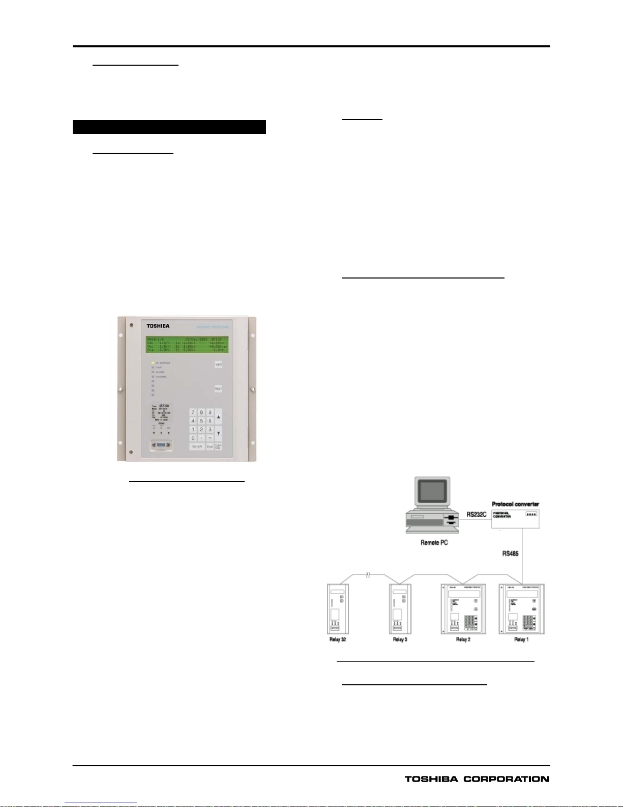
USER INTERFACE
Relay Front Panel
The relay front panel incorporates the following user
interfaces. Setting the relay and viewing stored data are
possible using the Liquid Crystal Display (LCD) and
operation keys.
- 40 character, four line LCD with back light
- Eight Light Emitting Diodes (LED) including four that are
configurable
- Operation keys
- RS232C port
- Monitoring jacks
Figure 13 shows the relay front panel.
Figure 13 Relay front panel
The following items can be displayed on the LCD.
- Setting
- Metering
- Event records
- Fault records
- The number of disturbance records
- Fault location
- Any failure code detected by the automatic supervision
Password protection can be provided from the setting menu
on the LCD to provide security for relay setting changes.
After the password has been set, the password must be
entered to access the setting menu from a local or remote PC
as well as on the LCD.
The contents of metering, fault records, and relay failures
can be monitored by pressing the VIEW key. The VIEW key
can be pressed without removing the relay front cover.
Arbitrary signals can be assigned to the four user
configurable LEDs.
Two monitoring jacks are operable when the test mode is
selected in the LCD window. An oscilloscope can be
connected to the relay through these jacks. Selection of
output signals on the monitoring jacks can be set from the
menu.
Local PC
The user can communicate with the GRZ100 from a local
PC via the RS232C port on the relay fascia. The following data
can be viewed or analysed on the local PC with RSM100
software.
- Setting
- Metering
- Event records
- Fault records
- Disturbance records
- Fault location
Relay Setting and Monitoring (RSM)
GRZ100 can be connected to the RSM system via the
RS485 interface at the rear of the relay. The user can
operate the relay from a remote PC in the same way as
from a local PC.
Figure 14 shows the configuration of the RSM system via
the protocol converter G1PR2 (option). The G1PR2 can be
provided with maximum 8 ports and each port supports 32
relays addressing.
A maximum of 32 x 8 relays can be connected to the
remote PC in multi-drop mode, via the protocol converter.
The RSM100 software is also used to communicate with the
relay and to view or analyze disturbance records on the
remote PC.
The data transmission rate between relays and the protocol
converter is 64kbps.
G1PR2
Figure 14 Relay setting and monitoring system
IEC60870-5-103 Communication
The relay can support the IEC60870-5-103 communication
protocol. This protocol is mainly used when the relay
communicates with a control system and is used to transfer
the measurand data, status data and general command
from the relay to the control system.
GRZ100
11
Relay Setting
The user can input or change settings using the operation
keys on the relay fascia or via a local or remote PC with the
RSM system.
Password protection is provided to change settings.
Eight active setting groups are provided. This allows the
user to set one group for normal operating conditions while
other groups may be set to cover alternative operating
conditions.
Configurable Binary Output Contacts
GRZ100 is provided with 13 to 41 user configurable
normally open output contacts used for indication and alarm.
The number of outputs varies according to the relay model.
Configurable Binary Inputs
GRZ100 is provided with 18 to 28 user configurable binary
inputs.
The number of inputs varies according to the relay model.
PLC Function
GRZ100 is provided with a PLC (Programmable Logic
Control) function allowing user-configurable sequence logics
on binary signals. Configurable binary inputs, binary outputs
and LEDs are programmed by the PLC function.
AUTOMATIC SUPERVISION
Automatic Monitoring Function
The automatic monitoring function will detect failures,
should they occur, that might cause unwanted operation.
The items monitored include the following:
- Analog input circuits
- Analog-to-digital converter
- Watchdog Timer
- Binary output circuits
- DC power supply circuits
- CPU
- Telecommunication circuit
- Relay address monitoring
Automatic Test Function for External
Communication
In the BOP scheme, a signal check-back test function is
provided to check the integrity of the signalling channels.
Alarms
In the unlikely event that a relay failure should occur, this
is detected by automatic monitoring and the LED
ALARM on the relay fascia is illuminated. A binary
“RELAY FAILURE” output is simultaneously operated
and the date/time of any such failure would be stored in
the event record.
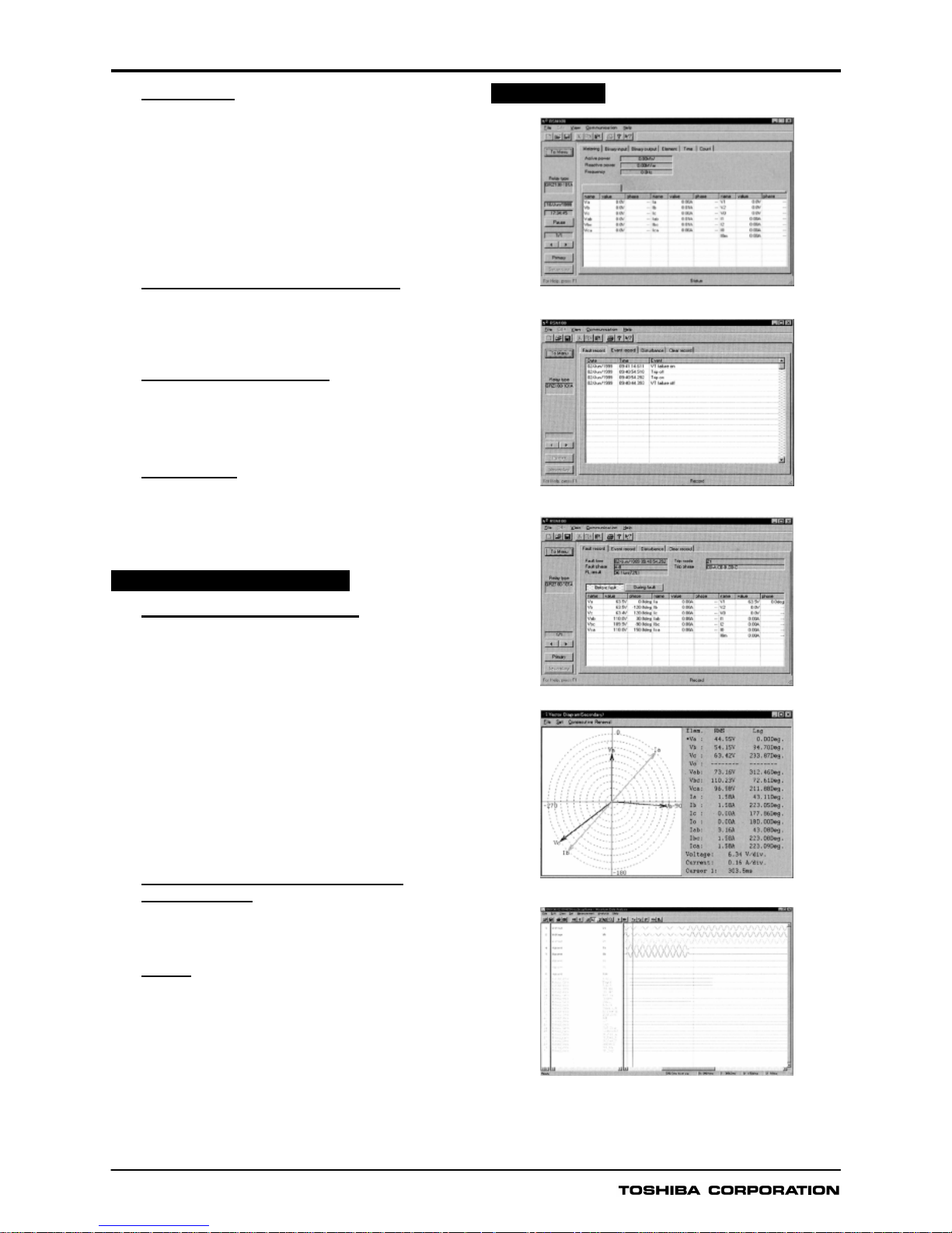
PC DISPLAY
Metering
Event record
Fault record
Vector record
Data analysis

GRZ100
12
TECHNICAL DATA
Ratings
AC current In: 1A or 5A
AC voltage Vn: 100V, 110V, 115V, 120V
Frequency: 50Hz or 60Hz
DC power supply: 110Vdc/125Vdc (Operative range: 88 - 150Vdc)
220Vdc/250Vdc (Operative range: 176 - 300Vdc)
48Vdc/54Vdc/60Vdc (Operative range: 38.4 - 72Vdc)
24Vdc/30Vdc (Operative range: 19.2 – 36Vdc)
AC ripple on DC supply IEC60255-11 maximum 12%
DC supply interruption IEC60255-11
Permissive duration of DC supply voltage
interruption to maintain normal operation:
Restart time:
less than 50ms at 110V
less than 10s
Binary input circuit DC voltage 110Vdc/125Vdc
220Vdc/250Vdc
48Vdc/54Vdc/60Vdc
24Vdc/30Vdc
Overload Ratings
AC current input
AC voltage input
4 times rated continuous
100 times rated for 1s
2 times rated continuous
2.5 times rated for 1s
Burden
AC current input 0.2VA per phase (at rated 5A)
0.4 VA at zero-sequence circuit (at rated 5A)
0.1VA per phase (at rated 1A)
0.3 VA at zero-sequence circuit (at rated 1A)
AC voltage input 0.1VA (at rated voltage)
DC power supply: less than15W (quiescent)
less than 25W (operation)
Binary input circuit: ≤ 0.5W/input at 110Vdc
CT Ratio Setting
CT ratio 1 to 20000 in 1 steps
Full Scale of Current for Measurement
Current 65 times rated current
Phase Fault Distance Measuring Element
Z1S, Z2S and Z1XS
Z1S
θ1
Z1S θ2
ZFS, ZR1S and ZR2S
Z3S and Z4S
Characteristic angle
Z1S and Z4S offset
ZNDS
Blinder (BFRS1, BFRS2, BFRS3, BRRS, BNDS)
BRLS: Linked with BRRS
Characteristic angle: (BFRS1, BFRS2, BFRS3, BRRS, BNDS)
Characteristic angle (BFLS)
0.10 to 250.00Ω in 0.01Ω steps (1A relay)
0.01 to 50.00Ω in 0.01Ω steps (5A relay)
0° to 45° in 1° steps
45° to 90° in 1° steps
0.1 to 250.0Ω in 0.1Ω steps (1A relay)
0.01 to 50.00 in 0.01Ω steps (5A relay)
0.1 to 250.0Ω in 0.1Ω steps (1A relay)
0.01 to 50.00 in 0.01Ω steps (5A relay)
45° to 90° in 1° steps
7.5Ω fixed (1A relay)
1.5Ω fixed (5A relay)
0.1 to 250.0Ω in 0.1Ω steps (1A relay)
0.01 to 50.00 in 0.01Ω steps (5A relay)
0.5 to 100.0Ω in 0.1Ω steps (1A relay)
0.10 to 20.00Ω in 0.01Ω steps (5A relay)
75° fixed
90° to 135°
 Loading...