

Toshiba GRT100 Series Instruction Manual
( Ver. 3.1)
6 F 2 S 0 7 8 9
INSTRUCTION MANUAL
TRANSFORMER PROTECTION RELAY
GRT100 - B
© Toshiba Energy Systems & Solutions Corporation 2017
All Rights Reserved.
6 F 2 S 0 7 8 9
DANGER
WARNING
Safety Precautions
Before using this product, be sure to read this chapter carefully.
This chapter describes safety precautions when using the GRT100. Before installing and using
the equipment, read and understand this chapter thoroughly.
Explanation of symbols used
Signal words such as DANGER, WARNING, and two kinds of CAUTION, will be followed by
important safety information that must be carefully reviewed.
Indicates an imminently hazardous situation which will result in death or
serious injury if you do not follow instructions.
Indicates a potentially hazardous situation which could result in death or
serious injury if you do not follow instructions.
CAUTION Indicates a potentially hazardous situation which if not avoided, may result in
minor injury or moderate injury.
CAUTION Indicates a potentially hazardous situation which if not avoided, may result in
property damage.
1

6 F 2 S 0 7 8 9
DANGER
WARNING
Current transformer circuit
Never allow the current transformer (CT) secondary circuit connected to this equipment to be
opened while the primary system is live. Opening the CT circuit will produce a dangerous high
voltage.
Exposed terminals
Do not touch the terminals of this equipment while the power is on, as the high voltage generated
is dangerous.
Residual voltage
Hazardous voltage can be present in the DC circuit just after switching off the DC power supply.
It takes about 30 seconds for the voltage to discharge.
CAUTION
Earth
Earth the earthing terminal of the equipment securely.
CAUTION
Operation conditions
Use the equipment within the range of ambient temperature, humidity and dust as detailed in the
specification and in an environment free of abnormal vibration.
Ratings
Before applying AC voltage and current or DC power supply to the equipment, check that they
conform to the equipment ratings.
Printed circuit board
Do not attach and remove the printed circuit board while the DC power to the equipment is on, as
this may cause the equipment to malfunction.
Battery
Avoid placing the back side of the printed circuit board with a battery (SPM board) directly on
top of a metal conductor or wrapping it with metal foil, as this may short-circuit the battery power
supply. However, the board may be placed on an antistatic conductive mat.
External circuit
When connecting the output contacts of the equipment to an external circuit, carefully check the
supply voltage used and prevent the connected circuit from overheating.
Connection cable
Carefully handle the connection cable without applying excessive force.
Modification
Do not modify this equipment, as this may cause the equipment to malfunction, and any such
modifications will invalidate the warranty.
2

6 F 2 S 0 7 8 9
Disposal
When disposing of this product, do so in a safe manner according to local regulations.
This product contains a lithium-ion battery, which should be removed at the end-of-life of the
product. The nominal backup time of a lithium-ion battery is one year after the shipment from the
factory. The battery must be recycled or disposed of in accordance with local regulations. The
battery can be removed by withdrawing the Signal Processing module (SPM) from the relay case,
and cutting the connecting leads and plastic strap which hold the battery.
3

6 F 2 S 0 7 8 9
Contents
Safety Precautions 1
1. Introduction 8
2. Application Notes 9
2.1 Application 9
2.2 Protection Scheme 10
2.3 Current Differential Protection 12
2.4 Restricted Earth Fault Protection 22
2.5 Overcurrent Protection 26
2.6 Thermal Overload Protection 31
2.7 Frequency Protection 32
2.8 Overexcitation Protection 34
2.9 Trip by External Devices 36
2.10 Tripping Output 37
2.11 Characteristics of Measuring Elements 38
2.3.1 Differential Scheme 12
2.3.2 Matching of CT Secondary Currents 14
2.3.3 Connection between CT Secondary Circuit and the GRT100 15
2.3.4 Setting 16
2.11.1 Percentage Current Differential Element DIF 38
2.11.2 High-set Overcurrent Element HOC 39
2.11.3 Restricted Earth Fault Element REF 39
2.11.4 Inverse Time Overcurrent Element OCI and EFI 40
2.11.5 Definite Time Overcurrent element OC and EF 41
2.11.6 Thermal Overload Element THR 42
2.11.7 Frequency Element FRQ 44
2.11.8 Overexcitation Element V/F 44
3. Technical Description 45
3.1 Hardware Description 45
3.2 Input and Output Signals 55
3.3 Automatic Supervision 58
3.1.1 Outline of Hardware Modules 45
3.1.2 Transformer Module 48
3.1.3 Signal Processing Module 49
3.1.4 Binary Input and Output Module 50
3.1.5 Human Machine Interface (HMI) Module 53
3.2.1 Input Signals 55
3.2.2 Binary Output Signals 56
3.2.3 PLC (Programmable Logic Controller) Function 57
3.3.1 Basic Concept of Supervision 58
3.3.2 Relay Monitoring and Testing 58
4

6 F 2 S 0 7 8 9
3.3.3 Failure Alarms 59
3.3.4 Trip Blocking 59
3.3.5 Setting 60
3.4 Recording Function 61
3.4.1 Fault Recording 61
3.4.2 Event Recording 62
3.4.3 Disturbance Recording 63
3.5 Metering Function 65
4. User Interface 66
4.1 Outline of User Interface 66
4.1.1 Front Panel 66
4.1.2 Communication Ports 68
4.2 Operation of the User Interface 69
4.2.1 LCD and LED Displays 69
4.2.2 Relay Menu 71
4.2.3 Displaying Records 74
4.2.4 Displaying the Status 77
4.2.5 Viewing the Settings 82
4.2.6 Changing the Settings 82
4.2.7 Testing 98
4.3 Personal Computer Interface 102
4.4 Relay Setting and Monitoring System 102
4.5 IEC 60870-5-103 Interface 103
4.6 Modbus Interface 103
4.7 Clock Function 103
5. Installation 105
5.1 Receipt of Relays 105
5.2 Relay Mounting 105
5.3 Electrostatic Discharge 105
5.4 Handling Precautions 105
5.5 External Connections 106
6. Commissioning and Maintenance 107
6.1 Outline of Commissioning Tests 107
6.2 Cautions 108
6.2.1 Safety Precautions 108
6.2.2 Cautions on Tests 108
6.3 Preparations 109
6.4 Hardware Tests 110
6.4.1 User Interfaces 110
6.4.2 Binary Input Circuit 111
6.4.3 Binary Output Circuit 112
6.4.4 AC Input Circuits 113
6.5 Function Test 114
5

6 F 2 S 0 7 8 9
6.5.1 Measuring Element 114
6.5.2 Timer Test 130
6.5.3 Protection Scheme 132
6.5.4 Metering and Recording 132
6.6 Conjunctive Tests 133
6.6.1 On Load Test 133
6.6.2 Tripping Circuit Test 133
6.7 Maintenance 135
6.7.1 Regular Testing 135
6.7.2 Failure Tracing and Repair 135
6.7.3 Replacing Failed Modules 137
6.7.4 Resumption of Service 139
6.7.5 Storage 139
7. Putting Relay into Service 140
6

6 F 2 S 0 7 8 9
Appendix A Block Diagram 141
Appendix B Signal List 143
Appendix C Variable Timer List 159
Appendix D Binary Output Default Setting List 161
Appendix E Details of Relay Menu and LCD & Button Operation 165
Appendix F Case Outline 173
Appendix G External Connections 179
Appendix H Relay Setting Sheet 185
Appendix I Commissioning Test Sheet (sample) 194
Appendix J Return Repair Form 200
Appendix K Technical Data 206
Appendix L Setting of REF Element 212
Appendix M Symbols Used in Scheme Logic 220
Appendix N Implementation of Thermal Model to IEC60255-8 224
Appendix O IEC60870-5-103: Interoperability and Troubleshooting 228
Appendix P Modbus: Interoperability and Troubleshooting 240
Appendix Q Inverse Time Characteristics 255
Appendix R Failed Module Tracing and Replacement 259
Appendix S Ordering 265
The data given in this manual are subject to change without notice. (Ver. 3.1)
7
6 F 2 S 0 7 8 9
Relay Type:
- Type GRT100; Numerical transformer protection relay
Relay Model:
- Model 100 series; 2 three-phase current inputs, applied to two-winding transformers
Model 101; 13 N/O programmable output contacts
Model 102; 23 N/O programmable output contacts
- Model 200 series; 3 three-phase current inputs, applied to two- and three-winding transformers
Model 201; 13 N/O programmable output contacts
Model 202; 23 N/O programmable output contacts
1. Introduction
The GRT100 provides transformer protection for two- or three- winding power transformers
connected to single, double or a one-and-a-half busbar system.
The GRT100 is member of the G-series numerical relays which are built on common hardware
modules and featured with the following functions:
Human interfaces on the relay front panel, and local and remote PCs
4 40 character LCD and keypad
RS232C and RS485 communication ports
Meeting and recording of event, fault and disturbance
IRIG-B time synchronization
Automatic supervision
User configurable binary output
GRT100 has two model series which differ according to the number of three-phase current inputs
for differential protection as follows:
Relay Type and Model
Model 100 series have 2 three-phase current inputs and can be applied to two-winding
transformers. Model 200 series have 3 three-phase current inputs and can be applied to two- and
three-winding transformers.
8

6 F 2 S 0 7 8 9
2. Application Notes
2.1 Application
The GRT100 provides high-speed transformer and reactor protection, and realises high
dependability and security for diverse faults such as single-phase faults, multi-phase faults,
overload and over-excitation.
The GRT100 is used as a main protection and backup protection of the following transformers
and reactors.
Two-winding or three-winding power transformers
Auto-transformers
Generator-transformer units
Shunt reactors
The GRT100 provides the stabilization for magnetizing inrush and overexcitation.
GRT100 provides the following metering and recording functions.
Metering
Fault records
Event records
Disturbance records
GRT100 provides the following human interfaces for relay setting or viewing of stored data.
Relay front panel: LCD, LED display and operation keys
Local PC
Remote PC
The relay can be integrated with a local PC or a remote PC through a communication port.
A local PC can be connected via the RS232C port on the front panel of the relay. A remote PC
can also be connected through the RS485 port on the rear panel of the relay.
9
6 F 2 S 0 7 8 9
Calculate 3I0
Calculate 3I0
GRT100
1CT
1nCT
2nCT
VT
HV
LV
2CT
1OC/1OCI
THR
FRQ
V/F
1EF/1EFI
DIFT
2OC/2OCI
2EF/2EFI
1REF
2REF
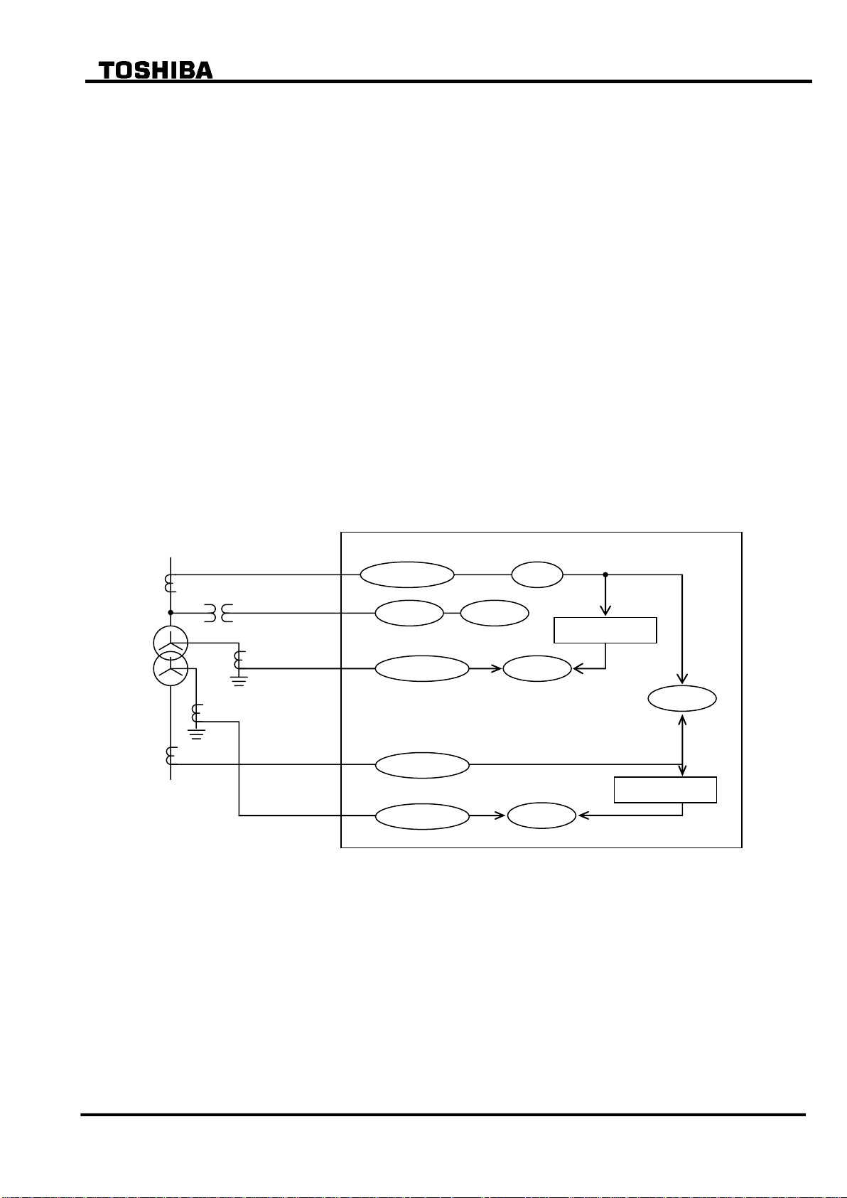
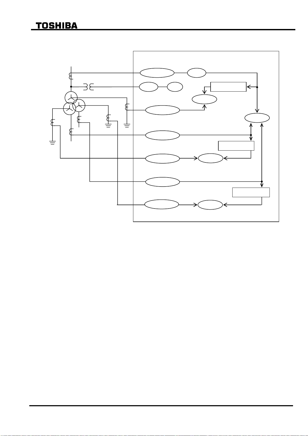
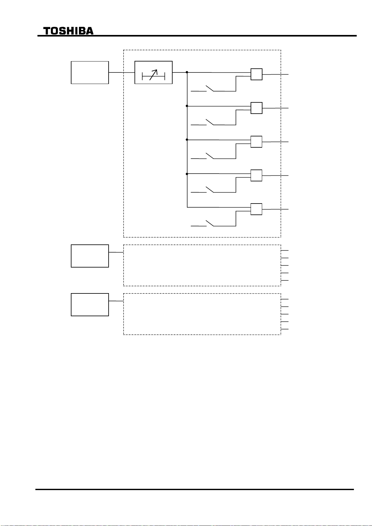
2.2 Protection Scheme
GRT100 provides the following protection schemes with measuring elements in parentheses.
Appendix A shows block diagrams of the GRT100 series.
Current differential protection (DIFT)
Restricted earth fault protection (1REF-3REF)
Time-overcurrent protection (1OC-3OC, 1OCI-3OCI, 1EF-3EF and 1EFI-3EFI)
Thermal overload protection (THR)
Frequency protection (FRQ)
Overexcitation protection (V/F)
Trip and/or indication of external devices (Buchholtz relay, pressure or temperature sensing
devices etc.)
The number of measuring elements for the restricted earth fault protection and time-overcurrent
protection is dependent on the relay models.
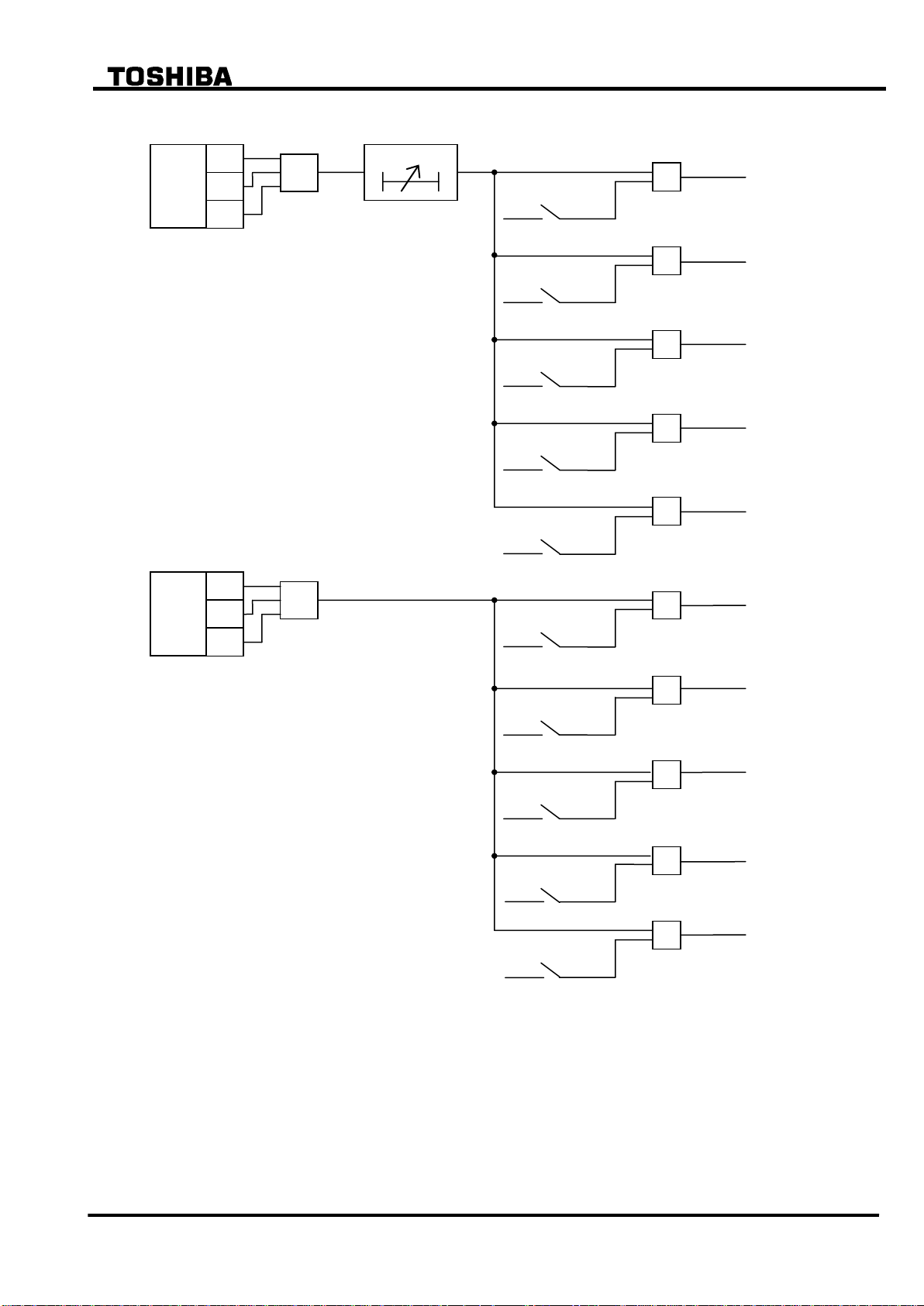
Figure 2.2.1 and 2.2.2 show the relationship between AC inputs and the measuring elements
applied in each model.
Figure 2.2.1 Measuring Elements of Model 100s
10
6 F 2 S 0 7 8 9
Calculate 3I0
Calculate 3I0
GRT100
1CT
VT
2nCT
3nCT
HV
LV
MV
3CT
2CT
1OC/1OCI
THR
FRQ
V/F
DIFT
2OC/2OCI
2EF/2EFI
1REF
Calculate 3I0
3OC/3OCI
2REF
1EF/1EFI
3REF
3EF/3EFI
1nCT
Figure 2.2.2 Measuring Elements of Model 200s
11
6 F 2 S 0 7 8 9
DIFT
I1
I2
i1
i2
id=i1+i2
Differential current
detection
Transformer
Primary
Secondary
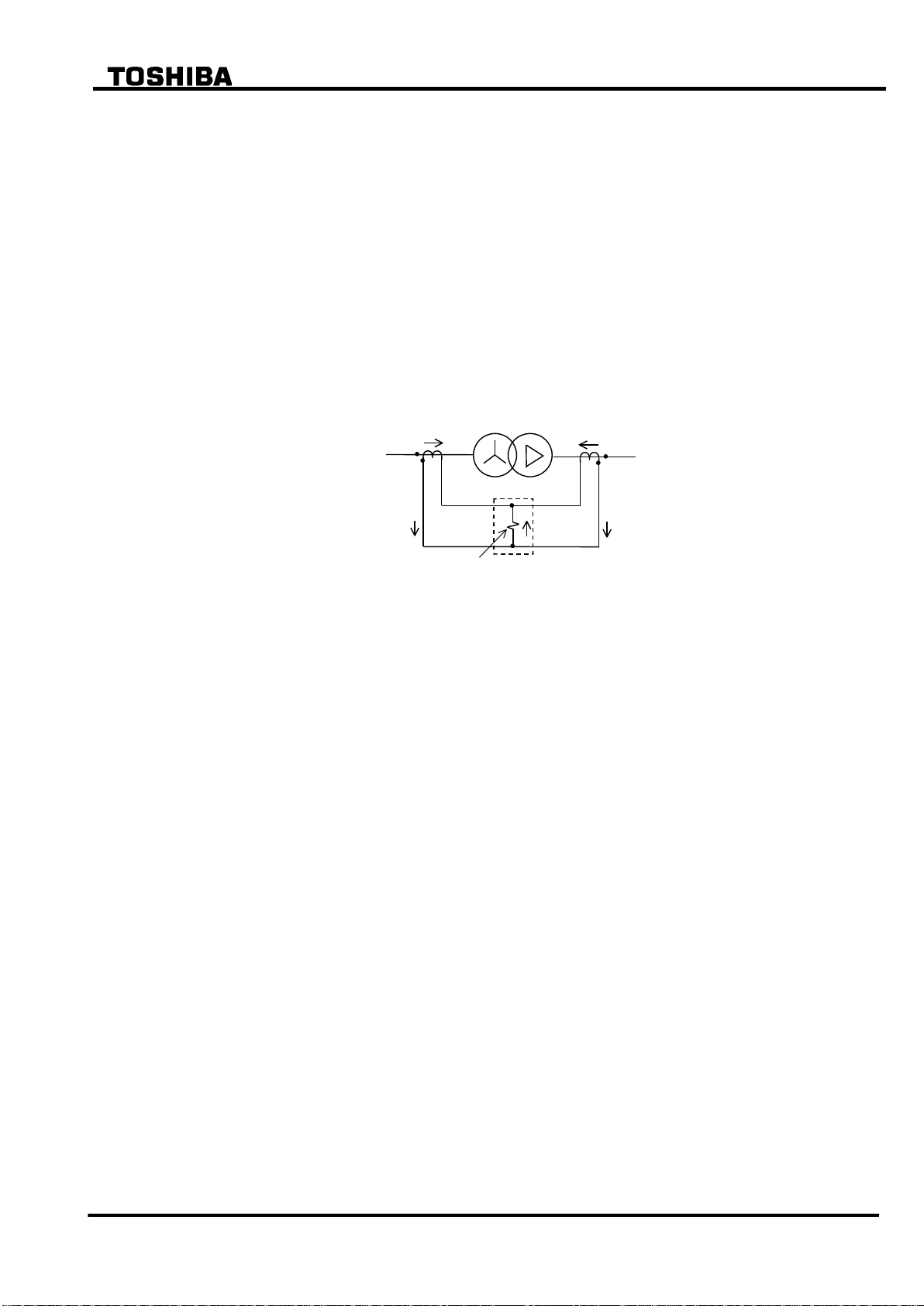
2.3 Current Differential Protection
2.3.1 Differential Scheme
Current differential protection DIFT provides an overall transformer protection deriving phase
current from each transformer winding, calculating the differential current on a per phase basis
and detecting phase-to-phase and phase-to-earth faults.
The current differential protection is based on Kirchhoff’s first law that the vector summation of
all currents flowing into a protected zone must be zero. Figure 2.3.1 shows the principle of
current differential protection. Differential current (id) is the vector summation of all terminal
current of the transformer. The differential current (id=i1+i2) is zero because the current (i1)
equals current (i2) during a load condition or an external fault. During an internal fault, the
differential current (id) is not zero because the current (i1) does not equal to the current (i2), and
the DIFT operates.
Figure 2.3.1 Current Differential Protection
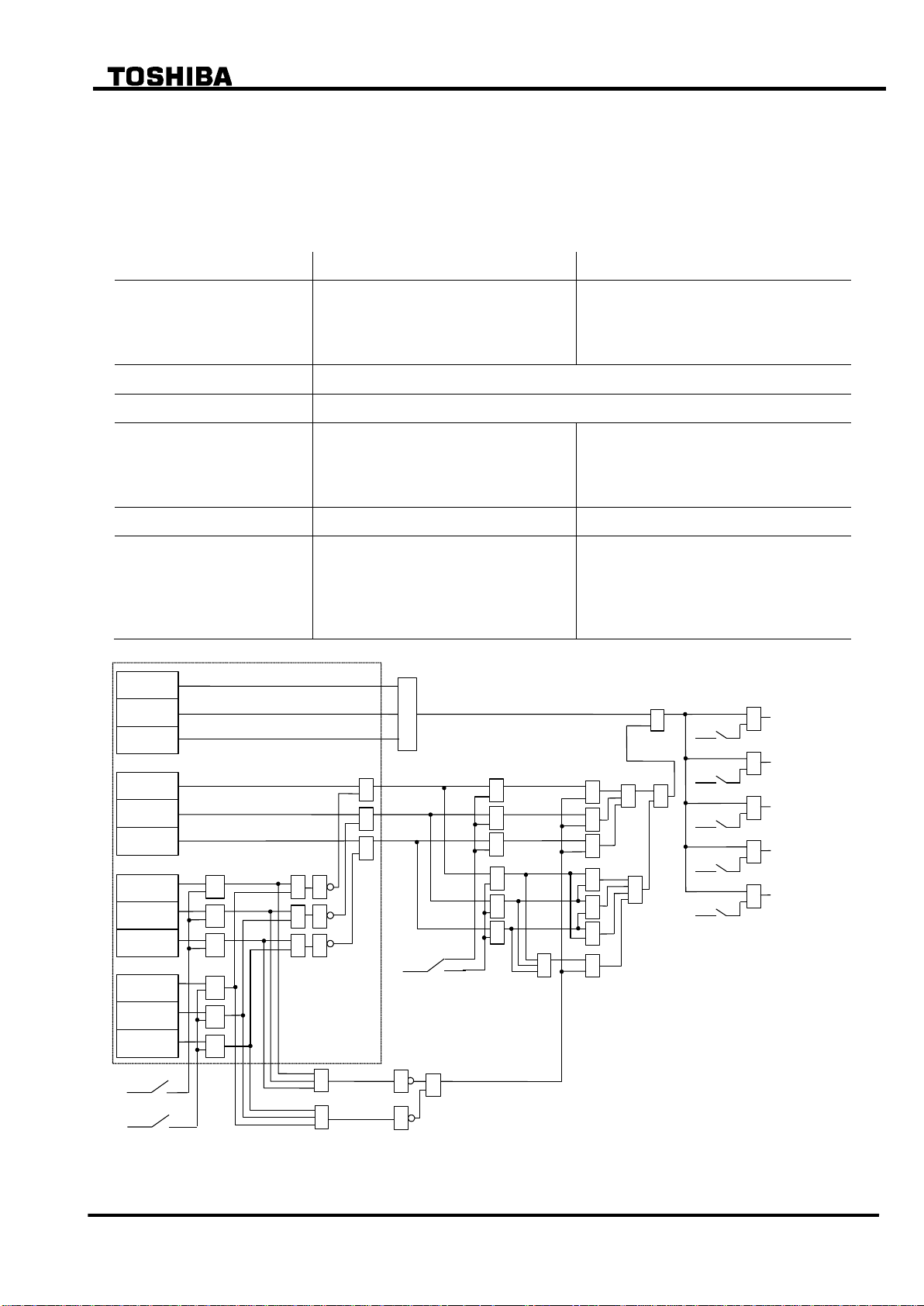
Scheme logic
Figure 2.3.2 shows the scheme logic of current differential protection. Current differential
element DIFT comprises sub-elements HOC, DIF, 2F and 5F which operate for the differential
current on a per phase basis.
Note: For the symbols used in the scheme logic, see Appendix M.
HOC is a high-set overcurrent element operating for the differential current. It provides
high-speed protection for heavy internal faults.
DIF is a percentage restraining element and has dual restraining characteristics, a weak restraint
in the small current region and a strong restraint in the large current region, to cope with
erroneous differential current which may be caused due to output imbalance of CTs in case of an
external fault. (For the characteristics, see Section 2.11.)
DIF output signal can be blocked when 2F or 5F element detects second harmonic inrush current
during transformer energization or fifth harmonic components during transformer
over-excitation. The blocking is enabled by setting the scheme switch [2F-LOCK] or [5F-LOCK]
to “ON”. The following two blocking scheme is selectable by the scheme switch [DIFTPMD].
(For details, see Table 2.3.1.)
“3POR”: When any one phase of 2F or 5F element operates, the trip by DIF element is
blocked in all three phases. The “3POR” is recommended for the transformers
whose second harmonic component may be low because its block function is
stronger than that of the “2PAND” below.
“2PAND”: Even if 2F or 5F element operates, the trip by DIF element is allowed when any
two phases or more of DIF element operate. The “2PAND” is recommended for
the transformers whose second harmonic component is higher. The relay does
not operate due to inruch current so long as second harmonic is detected by two
12
6 F 2 S 0 7 8 9
Setting
2PAND
3POR
Scheme
Even if 2F or 5F element operates during
manetising inrush, the trip by DIF element is
allowed when any two phases or more of DIF
element operate.
When any one phase of 2F or 5F element
operates during manetising inrush, the trip by
DIF element is blocked.
Sensitivity of 2F and 5F element
I2f/I1f 10 to 50% or I5f/I1f 10 to 50%
Scheme logic
Refer to Figure 2.3.2
Response against magnetizing
inrush
No problem:
When second or fifth hartmonic component
of any two phases is lower than their
sensitivity setting, the DIF may operate.
No problem:
When second or fifth hartmonic component of
any one phase is higher than their sensitivity
setting, the DIF is surely blocked.
Detection at internal fault
No problem
No problem
Application
The “2PAND” is recommended for a
transformer with small or midium capacity
whose second harmonic component in
inrush current is genarally higher than that of
transformer with large capacity.
The “3POR” is recommended for a transformer
with large capacity whose second harmonic
component in inrush current is generally lower.
This block function is stronger than that of the
“2PAND”.
HOC-A
HOC-B
HOC-C
2f-Lock
+
1
DIF-A
DIF-B
DIF-C
2f-A
2f-B
2f-C
5f-A
5f-B
5f-C
&
&
&
&
5f-Lock
+
DIFT
&
&
&
&
&
1
1
1
1
1
1
1
1
1
1
&
1
1
TRIP
DIFT-1
DIF1
+
&
DIFT-2
DIF2
+
&
DIFT-3
DIF3
+
&
& & & & &
& & & & &
&
&
DIFTPMD
+
2PAND
3POR
1
&
1
1
DIFT-4
DIF4
+
&
DIFT-5
DIF5
+
&
“ON”
“ON”
“ON”
“ON”
“ON”
“ON”
“ON”
phases of 2F element.
Protection by DIF and HOC can perform instantaneous three-phase tripping of up to five
breakers. Any of the five breaker tripping signals DIFT-1 to DIFT-5 are enabled or disabled by
the scheme switch [DIF1] to [DIF5] settings.
Table 2.3.1 Blocking Scheme during Magnetising inrush
Figure 2.3.2 Scheme Logic of Current Differential Protection
13

6 F 2 S 0 7 8 9
2.3.2 Matching of CT Secondary Currents
In order to restrain erroneous differential currents, the currents supplied to the differential
elements must be matched in phase and amplitude under through-load and through-fault
conditions.
In GRT100, the matching is performed through the settings.
2.3.2.1 Matching of Phase Angle
It is necessary to compensate for phase angle difference among line currents on each side of the
transformer when the transformer windings have both star- and delta-connections.
GRT100 can compensate for the phase angle difference by the setting and does not require CT
secondary circuit arrangement such as delta-connection on the star-connected side of the power
transformer which was common for the former transformer protection.
The phase angle matching is performed by inputting the phase angle of each winding according
to the hands of a clock. For details of the setting, refer to 2.3.4.
2.3.2.2 Matching of CT Ratio
When I1 to I3 relevant to 1CT to 3CT secondary currents are supplied, the differential current Id is
calculated employing the following equation,
Id = kct1I1 + kct2I2 + kct3I3
where kct1 to kct3 are settings corresponding to 1CT to 3CT.
The setting kct1 is obtained by using the following equation.
kct1 = In/I
= In/( 3 I
base1
) if the 1CT is delta-connected.
base1
where
In = rated secondary current of the 1CT.
I
= secondary current of the 1CT based on the kVA rating of the power transformer.
base1
= transformer capacity(kVA)/( 3 rated voltage(kV) /CT ratio of 1CT
If the 1CT secondary circuit is delta-connected, 3 I
is used instead of I
base1
in the equation
base1
above.
The settings kct2 and kct3 are obtained in the same way.
The differential current Id is zero under through-load and through-fault conditions.
kct1 I1 to kct3 I3 are equal to the rated secondary current of each CT when the rated line
currents based on the kVA rating of the power transformer flow.
14
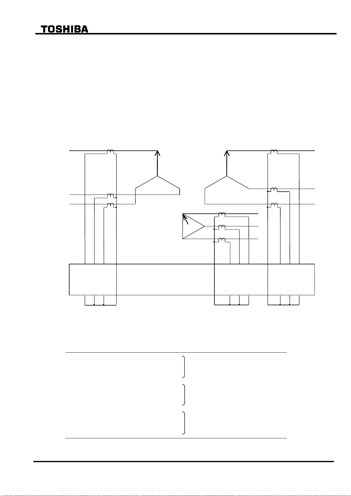
6 F 2 S 0 7 8 9
GRT100
Secondary
Primary
3
2 4 6
1
5
9
13
18
10
12
14
20
22
11
17
19
21
Tertiary
Model
Terminal block
Terminal number
Input current
100 series / 200 series
TB1
1-2 3-4
Current of primary winding
5-6 9-10 11-12
Current of secondary winding
13-14
17-18
19-20
Current of tertiary winding
21-22
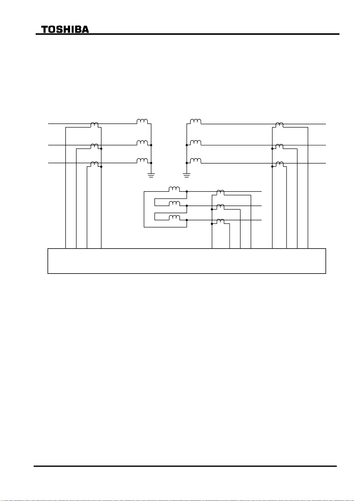
2.3.3 Connection between CT Secondary Circuit and the GRT100
The GRT100 is provided with 2 or 3 three-phase current input terminals depending on the relay
models.
To validate the phase angle matching mentioned above and input in-phase current of each
winding to the relay, connect the CT secondary circuits to the current input terminal of the relay
as follows;
As shown below, the phases used in the phase angle setting (indicated with arrowhead) must be
connected to the AC input terminals with the least number in the terminal group such as 1, 9, 17,
then other two phases should be connected to the terminals with larger number clockwise from
the setting phase, such as 3 and 5, 11 and 13, or 19 and 21.
Figure 2.3.3 Connection of CT Secondary Circuit and the GRT100
Terminal numbers and corresponding input currents are shown in the following table.
15

6 F 2 S 0 7 8 9
Element
Range
Step
Default
Remarks
DIFT
DIF
ik
0.10 1.00
()
0.01
0.30
Minimum operating current
p1
10 100%
1%
100%
% slope of small current region
p2
10 200%
1%
200%
% slope of large current region
kp
1.00 20.00(*)
0.01
1.00
Break point of dual characteristics
k2f
10 50%
1%
15%
Second harmonic detection
k5f
10 100%
1%
30%
Fifth harmonic detection
HOC
kh
2.00 20.00(*)
0.01
2.00
High-set overcurrent protection
CT matching
kct1
0.05 50.00
0.01
1.00
Primary winding
CT ratio
kct2
0.05 50.00
0.01
1.00
Secondary winding
kct3
0.05 50.00
0.01
1.00
Tertiary winding
d1
0 11
1 0 Primary winding
Phase angle
d2
0 11
1 0 Secondary winding
d3
0 11
1 0 Tertiary winding
Scheme switch
Enable or disable to
[DIFTPMD]
3POR / 2PAND
3POR
Trip mode
[2F – LOCK]
Off / On
On
block by second harmonic
[5F - LOCK]
Off / On
On
block by fifth harmonic
[DIF1] to [DIF5]
Off / On
(**)
output tripping signal
2.3.4 Setting
The following shows the setting elements necessary for the current differential protection and
their setting ranges. The setting can be performed on the LCD screen or PC screen.
(): Multiplier of CT secondary rated current including CT ratio sorrection.
(**): Default settings are dependent on the models. See Appendix H.
Setting of ik
ik determines minimum operation sensitivity of DIF element. ik is set as a ratio to the CT
secondary rated current.
Minimum setting of ik is determined from the maximum erroneous differential current under
normal operating conditions.
Setting of p1, p2 and kp
Percentage restraining factor (% slope)
= (Differential current) / (Through current)
= (Differential current) / [{(Incoming current) + (Outgoing current)} /2]
p1 is the percentage restraining factor which defines the DIF restraining characteristic in the
small current region. The setting is determined by the sum of:
16

6 F 2 S 0 7 8 9
Calculation steps
Primary
Secondary
Tertiary
(1) Transformer capacity (kVA)
40 103
(2) Voltage(kV)
154
66
11
(3) Rated line current(A)
150
350
2100
=(1)/( 3 (2))
(4) CT ratio
60
120
240
(5) Secondary rated line current(A) =(3)/(4)
2.50
2.92
8.75
(6) CT secondary rating(A)
5 5 5
(7) Setting =(6)/(5)
Kct1=2.00
Kct2=1.71
Kct3=0.57
CT accuracy error (generally considered as 5%)
Tap error: Error between maximum/minimum tap and the middle tap when taking the middle
tap of the tap changer as a reference.
Matching error: The error due to CT mismatch may be small enough to be neglected in the
setting.
Relay calculation error, and others (5%)
The recommended setting is “Sum of above” 1.5 (margin).
p2 is the percentage restraining factor which defines the restraining characteristic in the large
current region. The setting is determined from the maximum erroneous differential current which
is generated when a large through fault current flows.
kp is the break point of the dual percentage restraining characteristics. It is set above the
maximum operating current level of the transformer between the maximum forced-cooled rated
current and the maximum emergency overload current level, as a ratio to the CT secondary rated
current.
Setting of k2f
k2f is set to detect the second harmonic content in the inrush current during transformer
energization and blocks GRT100 to prevent incorrect operation due to the inrush current. A
setting of 15% is suggested if there is no data on the minimum second harmonic content.
Setting of k5f
k5f is set to detect the fifth harmonic content during transformer over-excitation and blocks
GRT100 to prevent incorrect operation due to transient over-excitation conditions.
A setting of 30% is suggested if there is no data on the minimum fifth harmonic content.
Setting of kh
Set above the estimated maximum inrush current.
Setting for CT ratio matching
Taking the transformer shown in Figure 2.3.4 as an example, the CT ratio matching settings kct1
to kct3 can be calculated as follows. For transformer capacity, take the maximum one from the
rated capacity of the three windings.
Note: Using the ratio of “CT rated-current (IN)” to “Transformer rated-current (IT)”, the user can
obtain a kct value (=IN/IT). We recommend the user chooses the CT whose rated-current is not
higher than the transformer rated-current multiplied by 2 so that the DIFT function can obtain the
17
6 F 2 S 0 7 8 9
Secondary
40MVA
66kV
Primary
40MVA
154kV
CT1
300/5
CT2
600/5
CT3
1200/5
GRT100
A B C
kct1
kct3
kct2
Tertiary
12MVA
11kV
current accurately. The kct range (from 2.00 to 8.00) is enough to operate the protection relay
correctly. When the value of the kct is set larger than 8 (that is, the kct value is set form 8.00 to
50.00), the protection relay can operate depending on the actual input of analog current and the
DIFT settings.
Figure 2.3.4 CT Ratio Matching
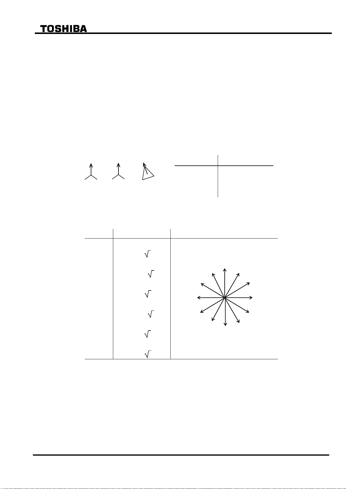
Setting for phase angle matching
The phase angle differences between line currents on each side of the power transformer are
corrected by setting according to the hands of a clock as follows:
Rule 1:
If all the windings are star-connected, then take one of the windings as a reference winding and
set 1 (= one o’clock) for it. For other winding(s), set the phase angle difference from the
reference winding by the expression of the leading angle. One hour corresponds to leading by
thirty degrees.
Example 1 If the setting winding leads the reference winding by 60, set 3 (= three o’clock).
Example 2 If the setting winding is in phase with the reference winding, set 1 (= one
o’clock).
Example 3 If the setting winding lags the reference winding by 60 (that is leading by 300),
set 11 (= eleven o’clock).
Rule 2:
If any of the windings are delta-connected, take one of the delta-connected winding(s) as a
18
6 F 2 S 0 7 8 9
Setting (d1 / d2 / d3)
Primary (d1)
11
Secondary (d2)
11
Tertiary (d3)
0
Setting
Calculation
Remarks
0
Ia = Ia
1
Ia = (Ia – Ic)/ 3
2
Ia = Ic
3
Ia = (Ic + Ib)/ 3
4
Ia = Ib
5
Ia = (Ib – Ia)/ 3
6
Ia = Ia
7
Ia = (Ia + Ic)/ 3
8
Ia = Ic
9
Ia = (Ic – Ib)/ 3
10
Ia = Ib
11
Ia = (Ia – Ib)/ 3
Tertiary
Secondary
Primary
0 1 2
3
4
5 6 7
8
9
10
11
Ia
Setting value
reference winding and set 0 (= noon) for it. For other star- or delta-connected winding(s), set
according to the Rule 1 mentioned above.
Example 1 If the setting winding leads the reference winding by 60, set 2 (= two o’clock).
Example 2 If the setting winding is in phase with the reference winding, set 0 (= noon).
Example 3 If the setting winding lags the reference winding by 60 (that is leading by 300),
set 10 (ten o’clock).
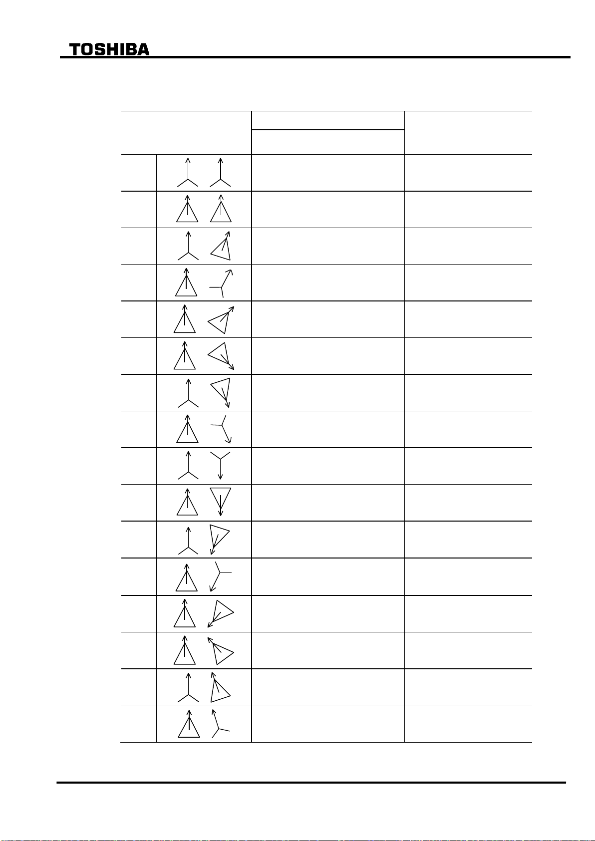
The settings for the two-winding transformer connections described in IEC60076-1 are listed in
Table 2.3.2.
Three-winding transformers are also set according to the above mentioned rules.
Example 4 Setting for star/star/delta transformer.
(Note) The following calculation is performed in the relay for phase angle correction.
19
6 F 2 S 0 7 8 9
Transformer connections
described in IEC60076-1
Settings for phase angle correction
Remarks
Primary , Secondary
(d1) , (d2)
Yy0
1 , 1
Dd0
0 , 0
Yd1
1 , 0
Dy1
0 , 11
Dd2
0 , 10
or 2 , 0
Based on primary winding.
Based on secondary winding.
Dd4
0 , 8
or 4 , 0
Based on primary winding.
Based on secondary winding.
Yd5
5 , 0
Dy5
0 , 7
Yy6
1 , 7
or 7 , 1
Based on primary winding.
Based on secondary winding.
Dd6
0 , 6
or 6 , 0
Yd7
7 , 0
Dy7
0 , 5
Dd8
0 , 4
or 8 , 0
Based on primary winding.
Based on secondary winding.
Dd10
0 , 2
or 10 , 0
Based on primary winding.
Based on secondary winding.
Yd11
11 , 0
Dy11
0 , 1
Table 2.3.2 Setting for Phase Angle Matching
(a) Settings for typical connections of 2-windings transformer
Note: A 2-windings transformer covers a 3-windings transformer with a stabilizing-winding circuit for
2-windings transformer protection relay can be applied.
20
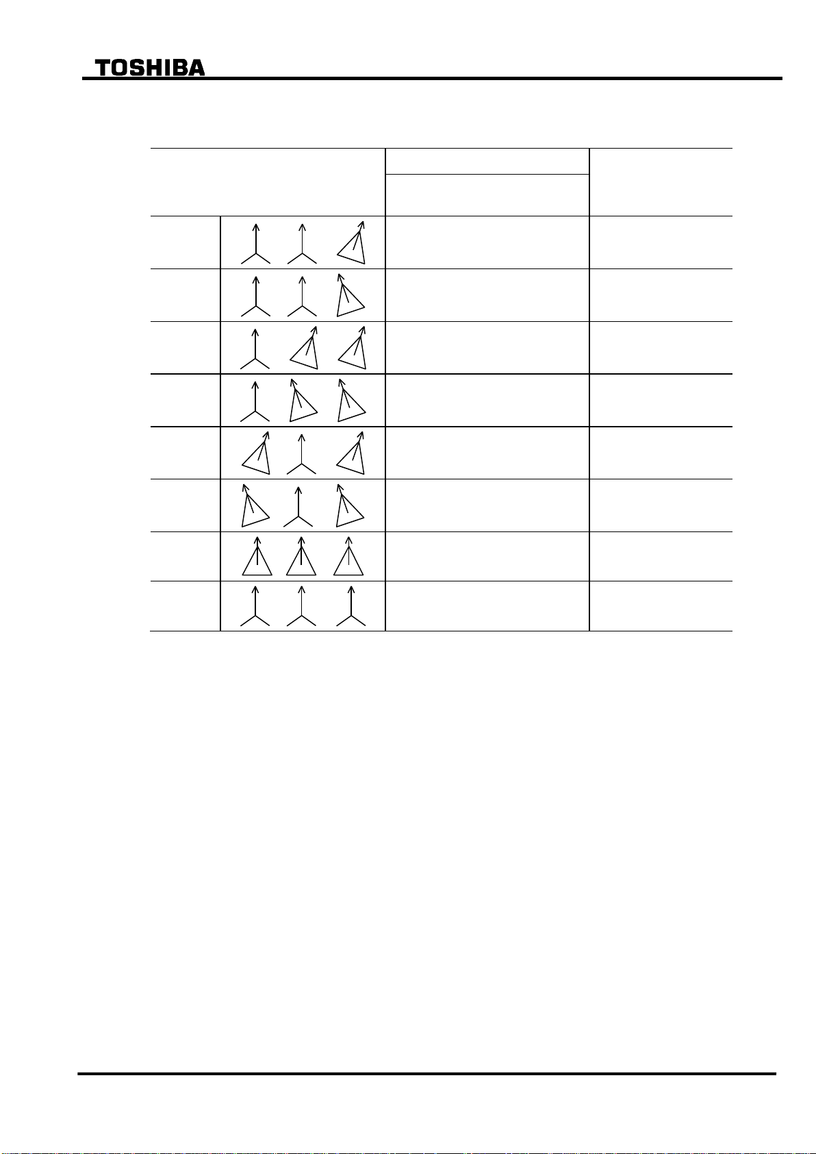
6 F 2 S 0 7 8 9
Transformer connections described in
IEC60076-1
Settings for phase angle correction
Remarks
Primary, Secondary, Tertiary
(d1) (d2) (d3)
Yy0d1
1 , 1 , 0
Yy0d11
11 , 11 , 0
Yd1d1
1 , 0 , 0
Yd11d11
11 , 0 , 0
Dy11d0
0 , 1 , 0
Dy1d0
0 , 11 , 0
Dd0d0
0 , 0 , 0
Yy0y0
1 , 1 , 1
(b) Settings for typical connections of 3-windings transformer
Note :
1. If all the windings are star-connected, then take one of the windings as a reference winding
and set 1 (= one hour) for it.
2. If any of the windings are delta-connected, take one of the delta-connected winding(s) as a
reference winding and set 0 for it.
21
6 F 2 S 0 7 8 9
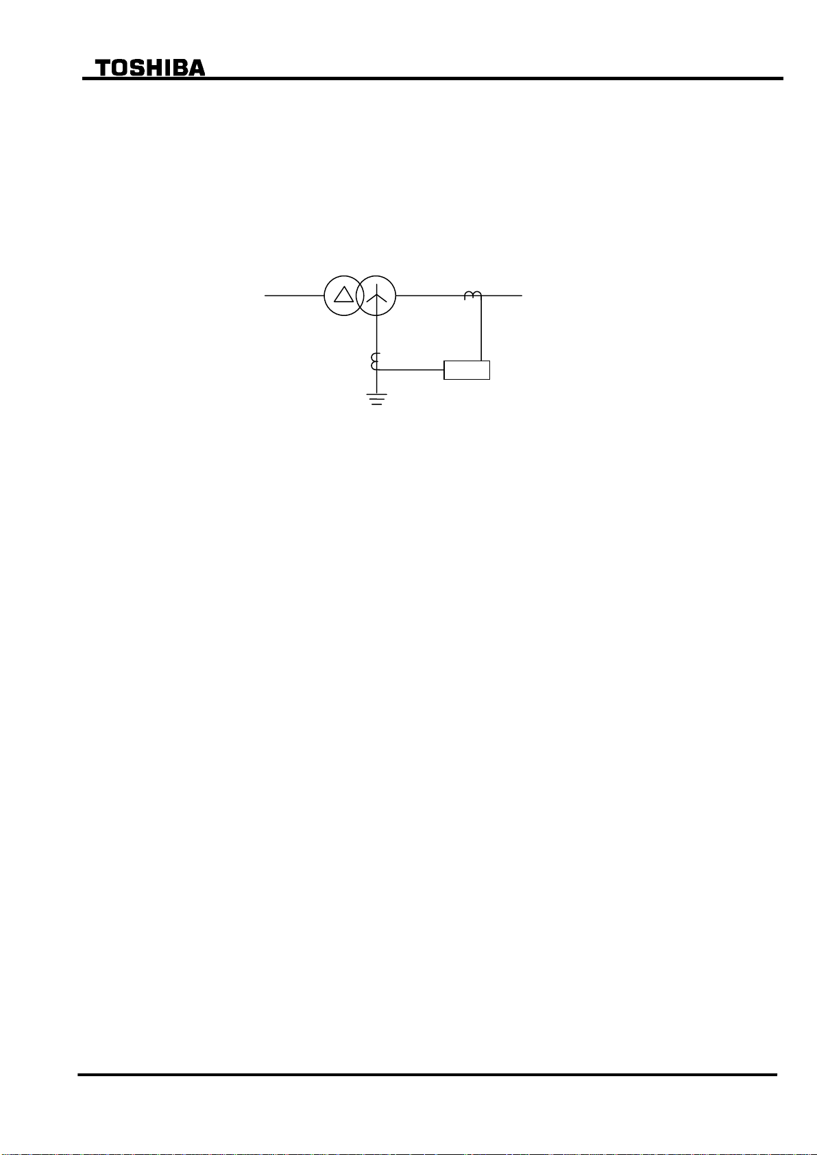
REF
2.4 Restricted Earth Fault Protection
Restricted earth fault protection (REF) is a zero-phase current differential scheme and applied for
a star-connected winding whose neutral is earthed directly or through a low impedance. It gives
highly sensitive protection for internal earth faults.
REF employs a low impedance current differential scheme which detects the differential current
between the residual current derived from the three-phase line currents and the neutral current in
the neutral conductor as shown in Figure 2.4.1
Figure 2.4.1 Restricted Earth Fault Protection
REF and the overall differential protection DIFT use the three-phase line currents in common.
GRT100 has two or three REF elements depending on the models to provide separate protection
for all star-connected and neutral-earthed windings. The elements have the same percentage
restraining characteristics and are stable for all faults outside the protected zone.
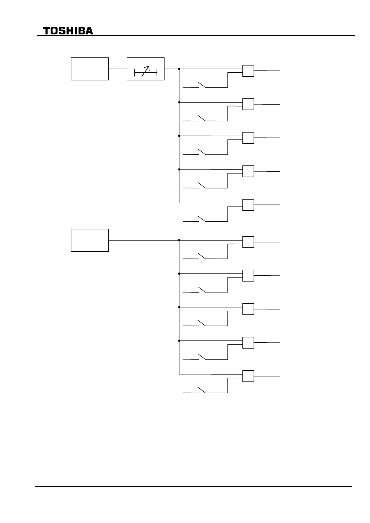
Figure 2.4.2 shows the scheme logic of restricted earth fault protection when three REF elements
are applied. Each REF element can perform instantaneous or time-delayed tripping of up to five
breakers. Any of the five breaker tripping signals 1REF-1 to 3REF-5 are enabled or disabled by
the scheme switch [1REF1] to [3REF5] settings.
22
6 F 2 S 0 7 8 9
3REF-1
3REF-2
3REF-3
3REF-4
3REF-5
1REF
T1REF
1REF-1
[1REF1]
&
1REF-2
1REF-3
1REF-4
1REF-5
0.00 - 10.00s
2REF
2REF-1
2REF-2
2REF-3
2REF-4
2REF-5
Same as above
3REF
Same as above
[1REF2]
[1REF3]
&
&
[1REF4]
&
[1REF5]
&
0
t
“ON”
“ON”
“ON”
“ON”
“ON”
Figure 2.4.2 Scheme Logic of Restricted Earth Fault Protection
Appendix L shows applications of the three REF elements to various types of transformers.
When protecting a two- or three-winding transformer, 1REF, 2REF and 3REF elements should
be applied to the primary (or high-voltage) winding, secondary (or medium-voltage) winding and
tertiary (or low-voltage) winding respectively. This is valid for an auto-transformer protection
but the application must refer to Appendix L.
In the application to auto-transformers, one REF element may introduce two or three line
currents and one neutral current as shown in the Appendix L. 1REF to 3REF elements recognize
the number of the line currents according to the scheme switch setting of [1REF] to [3REF].
23

6 F 2 S 0 7 8 9
Element
Range
Step
Default
Remarks
1REF
1ik
0.05 0.50(*)
0.01
0.50
Minimum operating current
1kct1
1.00 50.00
0.01
1.00
1kct2
1.00 50.00
0.01
1.00
CT ratio matching
1kct3
1.00 50.00
0.01
1.00
1p2
50 100%
1%
100%
% slope of DF2
1kp
0.50 2.00(*)
0.01
1.00
DF2 sensitivity
2REF
2ik
0.05 0.50(*)
0.01
0.50
Minimum operating current
2kct1
1.00 50.00
0.01
1.00
2kct2
1.00 50.00
0.01
1.00
CT ratio matching
2kct3
1.00 50.00
0.01
1.00
2p2
50 100%
1%
100%
% slope of DF2
2kp
0.50 2.00(*)
0.01
1.00
DF2 sensitivity
3REF
3ik
0.05 0.50(*)
0.01
0.50
Minimum operating current
3kct1
1.00 50.00
0.01
1.00
3kct2
1.00 50.00
0.01
1.00
CT ratio matching
3kct3
1.00 50.00
0.01
1.00
3p2
50 100%
1%
100%
% slope of DF2
3kp
0.50 2.00(*)
0.01
1.00
DF2 sensitivity
T1REF
0.00 10.00s
0.01s
0.00s
T2REF
0.00 10.00s
0.01s
0.00s
Delayed tripping
T3REF
0.00 10.00s
0.01s
0.00s
Scheme switch
[1REF1] to [1REF5]
[2REF1] to [2REF5]
[3REF1] to [3REF5]
[1REF] to [3REF]
Off/On
Off/On
Off/On
1Io/2Io/3Io
(**)
(**)
(**)
1Io
Enable or disable to output
tripping signal
Number of line currents input to
1REF, 2REF and 3REF elements
Setting
The following shows the setting elements for the restricted earth fault protection and their setting
ranges.
Setting of ik (1ik, 2ik and 3ik)
1ik, 2ik and 3ik of minimum operating current settings are set as a ratio to the line CT secondary
rated current. The minimum setting for ik is set to more than the maximum erroneous zero
sequence differential current under normal operating conditions, caused maily by CT errors. A
typical setting would be between 10% and 50%.
(*): Multiplier of secondary rated current
(**): Default settings are dependent on the models. See Appendix H.
24

6 F 2 S 0 7 8 9
Setting of kct (1kct1-1kct3, 2kct1-2kct3 and 3kct1-3kct3)
CT ratio matching is performed between the line CT(s) and the neutral CT by setting 1kct1-1kct3
for 1REF element, 2kct1-2kct3 for 2REF element and 3kct1-3kct3 for 3REF element. The
settings are obtained as a ratio of the line CTs ratio to the neutral CT ratio and the line CTs have
the notations shown in the Appendix L according to 1REF to 3REF applications.
For example, the settings of 1kct1, 1kct2, 2kct1 and 2kct2 are calculated;
1kct1 = (CT ratio of line CT 1ct-1)/(CT ratio of neutral CT 1nCT)
1kct2 = (CT ratio of line CT 1ct-2)/(CT ratio of neutral CT 1nCT)
2kct1 = (CT ratio of line CT 2ct-1)/(CT ratio of neutral CT 2nCT)
2kct2 = (CT ratio of line CT 2ct-2)/(CT ratio of neutral CT 2nCT)
where,
CT ratio = (primary rated current)/(secondary rated current).
Setting of scheme switch [1REF] to [3REF]
[1REF] to [3REF] are set to "1I0", "2I0" or "3I0" when they introduce one, two or three line
currents respectively.
25

6 F 2 S 0 7 8 9
2.5 Overcurrent Protection
GRT100 provides definite time and inverse time overcurrent elements for both phase faults and
earth faults, separately for each transformer winding. Three phase currents from each set of line
CTs are used for the phase fault protection elements, while the earth fault protection is based on
the neutral CT input. These elements can be used selectively depending on the requirements of
the particular application, but the following points should be noted:
In the case of large power transformers, overcurrent protection is usually employed only as
back-up protection for terminal faults, and for uncleared LV system faults. In such cases, the
overcurrent elements can be applied either on one or both sides of the transformers as
required.
Coverage of internal transformer faults is generally limited.
It is common practice to apply IDMTL phase and earth fault overcurrent protection as
back-up for the LV system. Current and time settings must be arranged to grade with
downstream relays and fuses. The phase fault current setting must also be set to exceed the
maximum overload current.
High-set instantaneous overcurrent protection can be applied on the primary side to provide
back-up protection for terminal faults. The current setting must be higher than the maximum
through-fault current to ensure that the element does not operate for faults on the LV side.
One of the following IEC-standard-compliant inverse time characteristics or one long time
inverse characteristic is available for the inverse current protection.
・standard inverse IEC 60255-3
・very inverse IEC 60255-3
・extremely inverse IEC 60255-3
Up to three definite time elements (1OC to 3OC) and inverse time elements (1OCI to 3OCI) input
three phase currents from line CTs in the transformer windings.
Up to three definite time elements (1EF to 3EF) and inverse time elements (1EFI to 3EFI) input
neutral currents from CTs in the neutral circuit.
Figure 2.5.1 and Figure 2.5.2 show the scheme logic of overcurrent protection. Each element can
perform time-delayed tripping of up to five breakers. The breaker tripping signals are blocked by
the scheme switch settings.
The number of overcurrent elements applied depends on the relay models.
26
6 F 2 S 0 7 8 9
1OC-1
1
1
[1OC1]
&
T1OC
1OC
1OC-2
1OC-3
1OC-4
0.00 - 10.00s
1OC-5
C B A
1OCI
1OCI-1
1OCI-2
1OCI-3
1OCI-4
1OCI-5
C
B
A
[1OC2]
&
[1OC3]
&
[1OC4]
&
[1OC5]
&
[1OCI1]
&
[1OCI2]
&
[1OCI3]
&
[1OCI4]
&
[1OCI5]
&
t
0
“ON”
“ON”
“ON”
“ON”
“ON”
“ON”
“ON”
“ON”
“ON”
“ON”
Note: 2OC and 3OC provides the same logic as 1OC. 2OCI and 3OCI provides the same logic as
1OCI.
Figure 2.5.1 Scheme Logic of the Overcurrent Protection
27
6 F 2 S 0 7 8 9
1EF-1
T1EF
1EF-2
1EF-3
1EF-4
0.00 - 10.00s
1EF-5
1EFI-1
1EFI-2
1EFI-3
1EFI-4
1EFI-5
1EFI
1EF
[1EF1]
& & & & & & & & &
&
[1EF2]
[1EF3]
[1EF4]
[1EF5]
[1EFI1]
[1EFI2]
[1EFI3]
[1EFI4]
[1EFI5]
0
t
“ON”
“ON”
“ON”
“ON”
“ON”
“ON”
“ON”
“ON”
“ON”
“ON”
Note: 2EF and 3EF provides the same logic as 1EF. 2EFI and 3EFI provides the same logic as 1EFI.
Figure 2.5.2 Scheme Logic of the Overcurrent Protection for Earth Faults
28

6 F 2 S 0 7 8 9
Element
Range
Step
Default
Remarks
1OC
0.10 20.0(*)
0.01
2.00
Definite time overcurrent (line)
2OC
0.10 20.0(*)
0.01
2.00
Definite time overcurrent (line)
3OC
0.10 20.0(*)
0.01
2.00
Definite time overcurrent (line)
T1OC
0.00 10.00s
0.01s
1.00s
Delayed tripping for 1OC
T2OC
0.00 10.00s
0.01s
1.00s
Delayed tripping for 2OC
T3OC
0.00 10.00s
0.01s
1.00s
Delayed tripping for 3OC
1OCI
0.10 5.00(*)
0.01
1.00
Inverse time overcurrent (line)
2OCI
0.10 5.00(*)
0.01
1.00
Inverse time overcurrent (line)
3OCI
0.10 5.00(*)
0.01
1.00
Inverse time overcurrent (line)
T1OCI
0.05 1.00
0.01
1.00
Time multiplier setting for 1OCI
T2OCI
0.05 1.00
0.01
1.00
Time multiplier setting for 2OCI
T3OCI
0.05 1.00
0.01
1.00
Time multiplier setting for 3OCI
1EF
0.10 20.00(*)
0.01
2.00
Definite time overcurrent (neutral)
2EF
0.10 20.00(*)
0.01
2.00
Definite time overcurrent (neutral)
3EF
0.10 20.00(*)
0.01
2.00
Definite time overcurrent (neutral)
T1EF
0.00 10.00s
0.01s
1.00s
Delayed tripping for 1EF
T2EF
0.00 10.00s
0.01s
1.00s
Delayed tripping for 2EF
T3EF
0.00 10.00s
0.01s
1.00s
Delayed tripping for 3EF
1EFI
0.10 5.00(*)
0.01
1.00
Inverse time overcurrent (neutral)
2EFI
0.10 5.00(*)
0.01
1.00
Inverse time overcurrent (neutral)
3EFI
0.10 5.00(*)
0.01
1.00
Inverse time overcurrent (neutral)
T1EFI
0.05 1.00
0.01
1.00
Time multiplier setting for 1EFI
T2EFI
0.05 1.00
0.01
1.00
Time multiplier setting for 2EFI
T3EFI
0.05 1.00
0.01
1.00
Time multiplier setting for 3EFI
Scheme switch
M1OCI to M3OCI
M1EFI to M3EFI
Long-Std-Very-Ext
Long-Std-Very-Ext
Std
Std
Inverse time characteristic selection of
OCI elements
EFI elements
Scheme switch
[1OC1] to [3OC5]
[1OCI1] to [3OCI5]
[1EF1] to [3EF5]
[1EFI1] to [3EFI5]
Off/On
(**)
Enable or disable tripping by
OC elements
OCI elements
EF elements
EFI elements
Setting
The following shows the setting elements for the overcurrent protection and their setting ranges.
(*) : Multiplier of CT secondary rated current
(**) : Default settings are dependent on the models. See Appendix H.
29
 Loading...