

Toshiba GRL100-501B, GRL100-101B, GRL100-311B, GRL100-411B, GRL100-511B Instruction Manual
...
6 F 2 S 0 8 3 5
INSTRUCTION MANUAL
LINE DIFFERENTIAL RELAY
GRL100 - ∗∗∗B
© TOSHIBA Corporation 2005
All Rights Reserved.
( Ver. 2.4 )
R
Safety Precautions
Before using this product, please read this chapter carefully.
This chapter describes the safety precautions recommended when using the GRL100. Before
installing and using the equipment, this chapter must be thoroughly read and understood.
Explanation of symbols used
Signal words such as DANGER, WARNING, and two kinds of CAUTION, will be followed by
important safety information that must be carefully reviewed.
Indicates an imminently hazardous situation which will result in death or
DANGE
Indicates a potentially hazardous situation which could result in death or
WARNING
CAUTION Indicates a potentially hazardous situation which if not avoided, may result
serious injury if you do not follow the instructions.
serious injury if you do not follow the instructions.
in minor injury or moderate injury.
6 F 2 S 0 8 3 5
CAUTION Indicates a potentially hazardous situation which if not avoided, may result
in property damage.
⎯ 1 ⎯

R
DANGE
• Current transformer circuit
Never allow the current transformer (CT) secondary circuit connected to this equipment to be
opened while the primary system is live. Opening the CT circuit will produce a dangerously high
voltage.
WARNING
• Exposed terminals
Do not touch the terminals of this equipment while the power is on, as the high voltage generated
is dangerous.
• Residual voltage
Hazardous voltage can be present in the DC circuit just after switching off the DC power supply.
It takes approximately 30 seconds for the voltage to discharge.
• Fiber optic
6 F 2 S 0 8 3 5
Invisible laser radiation
Do not view directly with optical instruments.
Class 1M laser product (Transmission distance: 30km class)
- the maximum output of laser radiation: 0.2 mW
- the pulse duration: 79.2 ns
- the emitted wavelength(s): 1310 nm
CAUTION
• Earth
The earthing terminal of the equipment must be securely earthed.
CAUTION
• Operating environment
The equipment must only used within the range of ambient temperature, humidity and dust
detailed in the specification and in an environment free of abnormal vibration.
• Ratings
Before applying AC voltage and current or the DC power supply to the equipment, check that
they conform to the equipment ratings.
• Printed circuit board
Do not attach and remove printed circuit boards when the DC power to the equipment is on, as
this may cause the equipment to malfunction.
• External circuit
When connecting the output contacts of the equipment to an external circuit, carefully check the
supply voltage used in order to prevent the connected circuit from overheating.
• Connection cable
Carefully handle the connection cable without applying excessive force.
⎯ 2 ⎯

6 F 2 S 0 8 3 5
• Modification
Do not modify this equipment, as this may cause the equipment to malfunction.
• Short-bar
Do not remove a short-bar which is mounted at the terminal block on the rear of the relay before
shipment, as this may cause the performance of this equipment such as withstand voltage, etc., to
reduce.
• Tripping circuit connections
Must connect the FD (Fault Detector) output contact with A- to C-phase tripping output contacts
in series in case of the model 400 and 500 series.
• Disposal
When disposing of this equipment, do so in a safe manner according to local regulations.
This product contains a battery, which should be removed at the end-of-life of the product. The
battery must be recycled or disposed of in accordance with local regulations. The battery can be
removed by withdrawing the Signal Processing module (SPM) from the relay case, and cutting
the connecting leads and plastic strap which hold the battery.
⎯ 3 ⎯

Contents
Safety Precautions 1
1. Introduction 9
2. Application Notes 12
2.1 Protection Schemes 13
2.2 Current Differential Protection 14
2.3 Overcurrent Backup Protection 41
2.4 Transfer Trip Function 45
2.5 Out-of-step Protection 47
2.6 Thermal Overload Protection 49
2.7 Breaker Failure Protection 52
2.8 Tripping Output 55
2.9 Fault Detector 58
2.10 Autoreclose 61
2.11 Characteristics of Measuring Elements 81
6 F 2 S 0 8 3 5
2.2.1 Operation of Current Differential Protection 14
2.2.2 Segregated-phase Current Differential Protection 14
2.2.3 Zero-phase Current Differential Protection 15
2.2.4 Fail-safe Function 16
2.2.5 Remote Differential Trip 17
2.2.6 Transmission Data 19
2.2.7 Synchronized Sampling 19
2.2.8 Charging Current Compensation 25
2.2.9 Blind Zone Protection 27
2.2.10 Application to Three-terminal Lines 28
2.2.11 Dual Communication Mode 30
2.2.12 Application to One-and-a-half Breaker Busbar System 30
2.2.13 Setting 32
2.10.1 Application 61
2.10.2 Scheme Logic 63
2.10.3 Autoreclose Output Signals 80
2.11.1 Segregated-phase Current Differential Element DIF and DIFSV 81
2.11.2 Zero-phase Current Differential Element DIFG 82
2.11.3 Inverse Definite Minimum Time (IDMT) Overcurrent Element OCI and
EFI 83
2.11.4 Thermal Overload Element 84
2.11.5 Out-of-Step Element OST 84
2.11.6 Voltage and Synchronism Check Elements OVL, UVL, OVB, UVB and
SYN 85
2.11.7 Current change detection element OCD 86
2.11.8 Level Detectors 86
2.11.9 Fault Detector Elements 86
⎯ 4 ⎯

6 F 2 S 0 8 3 5
2.12 Communication System 89
2.12.1 Signaling Channel 89
2.12.2 Linking to Communication Circuit 90
2.12.3 Setup of Communication Circuit 91
2.12.4 Telecommunication Channel Monitoring 94
2.13 Fault Locator 95
2.13.1 Application 95
2.13.2 Calculation of Distance to Fault 96
2.13.3 Starting Calculation 98
2.13.4 Fault Location Display 98
2.13.5 Setting 98
3. Technical Description 102
3.1 Hardware Description 102
3.1.1 Outline of Hardware Modules 102
3.1.2 Transformer Module 109
3.1.3 Signal Processing and Communication Module 110
3.1.4 Binary Input and Output Module 111
3.1.5 Human Machine Interface (HMI) Module 116
3.1.6 Fault Detector Module 118
3.2 Input and Output Signals 119
3.2.1 Input Signals 119
3.2.2 Binary Output Signals 122
3.2.3 PLC (Programmable Logic Controller) Function 122
3.3 Automatic Supervision 123
3.3.1 Basic Concept of Supervision 123
3.3.2 Relay Monitoring 123
3.3.3 CT Circuit Current Monitoring 124
3.3.4 CT Circuit Failure Detection 125
3.3.5 Differential Current (Id) Monitoring 126
3.3.6 Telecommunication Channel Monitoring 126
3.3.7 GPS Signal Reception Monitoring (For GPS-mode only) 126
3.3.8 Relay Address Monitoring 126
3.3.9 Disconnector Monitoring 126
3.3.10 Failure Alarms 127
3.3.11 Trip Blocking 128
3.3.12 Setting 128
3.4 Recording Function 129
3.4.1 Fault Recording 129
3.4.2 Event Recording 130
3.4.3 Disturbance Recording 131
3.5 Metering Function 133
4. User Interface 134
4.1 Outline of User Interface 134
4.1.1 Front Panel 134
⎯ 5 ⎯

6 F 2 S 0 8 3 5
4.1.2 Communication Ports 136
4.2 Operation of the User Interface 138
4.2.1 LCD and LED Displays 138
4.2.2 Relay Menu 141
4.2.3 Displaying Records 143
4.2.4 Displaying the Status 147
4.2.5 Viewing the Settings 151
4.2.6 Changing the Settings 152
4.2.7 Testing 174
4.3 Personal Computer Interface 180
4.4 Relay Setting and Monitoring System 180
4.5 IEC 60870-5-103 Interface 181
4.6 Clock Function 181
5. Installation 182
5.1 Receipt of Relays 182
5.2 Relay Mounting 182
5.3 Electrostatic Discharge 182
5.4 Handling Precautions 182
5.5 External Connections 183
6. Commissioning and Maintenance 185
6.1 Outline of Commissioning Tests 185
6.2 Cautions 186
6.2.1 Safety Precautions 186
6.2.2 Cautions on Tests 186
6.3 Preparations 187
6.4 Hardware Tests 188
6.4.1 User Interfaces 188
6.4.2 Binary Input Circuit 189
6.4.3 Binary Output Circuit 190
6.4.4 AC Input Circuits 191
6.5 Function Test 192
6.5.1 Measuring Element 192
6.5.2 Timer 209
6.5.3 Protection Scheme 211
6.5.4 Metering and Recording 212
6.5.5 Fault Locator 212
6.6 Conjunctive Tests 213
6.6.1 On Load Test 213
6.6.2 Signaling Circuit Test 213
6.6.3 Tripping and Reclosing Circuit Test 213
6.7 Maintenance 216
6.7.1 Regular Testing 216
6.7.2 Failure Tracing and Repair 216
6.7.3 Replacing Failed Modules 218
⎯ 6 ⎯

6 F 2 S 0 8 3 5
6.7.4 Resumption of Service 220
6.7.5 Storage 220
7. Putting Relay into Service 221
⎯ 7 ⎯

6 F 2 S 0 8 3 5
Appendix A Block Diagram 223
Appendix B Signal List 227
Appendix C Variable Timer List 255
Appendix D Binary Output Default Setting List 257
Appendix E Details of Relay Menu 269
Appendix F Case Outline 279
Appendix G Typical External Connection 287
Appendix H Relay Setting Sheet 299
Appendix I Commissioning Test Sheet (sample) 321
Appendix J Return Repair Form 325
Appendix K Technical Data 331
Appendix L Symbols Used in Scheme Logic 343
Appendix M Multi-phase Autoreclose 347
Appendix N Data Transmission Format 351
Appendix O Example of DIF and DIFG Setting 357
Appendix P Programmable Reset Characteristics and Implementation of Thermal
Model to IEC60255-8 359
Appendix Q IEC60870-5-103: interoperability 363
Appendix R Failed Module Tracing and Replacement 377
Appendix S PLC Setting Sample 383
Appendix T Ordering 385
The data given in this manual are subject to change without notice. (Ver.2.4)
⎯ 8 ⎯

1. Introduction
The GRL100 provides high-speed phase-segregated current differential protection for use with
telecommunication systems, and ensures high reliability and security for diverse faults including
single-phase and multi-phase faults and double-faults on double-circuit lines, evolving faults
and high-impedance earth faults.
The GRL100 is used as a main protection for the following two- or three-terminal lines in EHV
or HV networks:
• Overhead lines or underground cables
Lines with weak infeed or non-infeed terminals
•
• Single or parallel lines
• Lines with heavy load current
• Short- or long-distance lines
The GRL100 can be used for lines associated with one-and-a-half busbar arrangement as well as
single or double busbar arrangement.
6 F 2 S 0 8 3 5
Furthermore, in addition to current differential protection, the GRL100 provides overcurrent backup,
thermal overload, out-of-step and breaker failure protection.
The GRL100 actuates high-speed single-shot autoreclose or multi-shot autoreclose.
For telecommunications, dedicated optical fibres or 64 kbits/s multiplexed comm unication links can
be employed.
The GRL100 is a member of the G-series family of numerical relays which utilise common
hardware modules with the common features:
The GRL100 provides the following metering and recording functions.
- Metering
- Fault record
- Event record
- Fault location
- Disturbance record
The GRL100 provides the following menu-driven human interfaces for relay setting or viewing
of stored data.
- Relay front panel; 4 × 40 character LCD, LED display and operation keys
- Local PC
- Remote PC
Password protection is provided to change settings. Eight active setting groups are provided.
This allows the user to set one group for normal operating conditions while other groups may be
set to cover alternative operating conditions.
GRL100 provides either two or three serial ports, and an IRIG-B port for an external clock
connection. A local PC can be connected via the RS232C port on the front panel of the relay.
Either one or two rear ports (RS485 or fibre optic) are provided for connection to a remote PC
and for IEC60870-5-103 communication with a substation control and automation system.
Further, Ethernet LAN port (TCP/IP protocol) can be provided as option.
Further, the GRL100 provides the following functions.
- Configurable binary inputs and outputs
⎯ 9 ⎯

6 F 2 S 0 8 3 5
- Programmable logic for I/O configuration, alarms, indications, recording, etc.
- Automatic supervision
The GRL100 has the following models:
Relay Type and Model
Relay Type:
- Type GRL100; Numerical current differential relay
Relay Model:
- For two terminal line, With No autoreclose
• Model 101; 18 binary inputs, 13 binary outputs, 6 binary outputs for tripping
• Model 102; 18 binary inputs, 23 binary outputs, 6 binary outputs for tripping
- For two terminal line, With autoreclose for single breaker scheme
• Model 201; 25 binary inputs, 19 binary outputs, 6 binary outputs for tripping
• Model 202; 28 binary inputs, 37 binary outputs, 6 binary outputs for tripping
• Model 204; 22 binary inputs (12-independent), 19 binary outputs, 3 binary outputs for tripping
• Model 206; 25 binary inputs (12-independent), 37 binary outputs, 3 binary outputs for tripping
- For two terminal line, With autoreclose for one-and-a-half breaker scheme
• Model 301; 25 binary inputs, 19 binary outputs, 6 binary outputs for tripping
• Model 302; 28 binary inputs, 37 binary outputs, 6 binary outputs for tripping
- For two terminal line, With autoreclose for single breaker scheme / With fault detector
• Model 401; 28 binary inputs, 31 binary outputs, 6 binary outputs for tripping
- For two terminal line, With autoreclose for one-and-a-half breaker scheme / With fault detector
• Model 501; 28 binary inputs, 31 binary outputs, 6 binary outputs for tripping
• Model 503; 28 binary inputs, 31 binary outputs, 6 binary outputs for tripping, TFC function
- For three terminal line, With No autoreclose
• Model 111; 18 binary inputs, 13 binary outputs, 6 binary outputs for tripping
• Model 112; 18 binary inputs, 23 binary outputs, 6 binary outputs for tripping
- For three terminal line, With autoreclose for single breaker scheme
• Model 211; 25 binary inputs, 19 binary outputs, 6 binary outputs for tripping
• Model 212; 28 binary inputs, 37 binary outputs, 6 binary outputs for tripping
• Model 214; 22 binary inputs (12-independent), 19 binary outputs, 3 binary outputs for tripping
• Model 216; 25 binary inputs (12-independent), 37 binary outputs, 3 binary outputs for tripping
- For three terminal line, With autoreclose for one-and-a-half breaker scheme
• Model 311; 25 binary inputs, 19 binary outputs, 6 binary outputs for tripping
• Model 312; 28 binary inputs, 37 binary outputs, 6 binary outputs for tripping
- For three terminal line, With autoreclose for single breaker scheme / With fault detector
• Model 411; 28 binary inputs, 31 binary outputs, 6 binary outputs for tripping
- For three terminal line, With autoreclose for one-and-a-half breaker scheme / With fault detector
• Model 511; 28 binary inputs, 31 binary outputs, 6 binary outputs for tripping
• Model 513; 28 binary inputs, 31 binary outputs, 6 binary outputs for tripping, TFC function
Model 100 has the minimum configuration, having only the segregated phase current differential
protection, overcurrent backup protection scheme and thermal overload protection.
Models 200 through 500 have a full protection scheme including additional high-sensitivity differential
protection for high-impedance earth faults, breaker failure protection, out-of-step protection,
fault locator and autoreclose function. Models 200 and 400 have a single- and multi-shot
autoreclose function and are used for single breaker autoreclose schemes. Models 300 and 500
have only a single-shot autoreclose function and are used for one-and-a-half breaker
(two-breaker) autoreclose schemes. Models 400 and 500 have an independent fault detector in
the form of a check relay, and provide the highest security. Models 503 and 513 have a CT
saturation countermeasure against the external through fault current in one-and-a-half breaker
schemes.
⎯ 10 ⎯
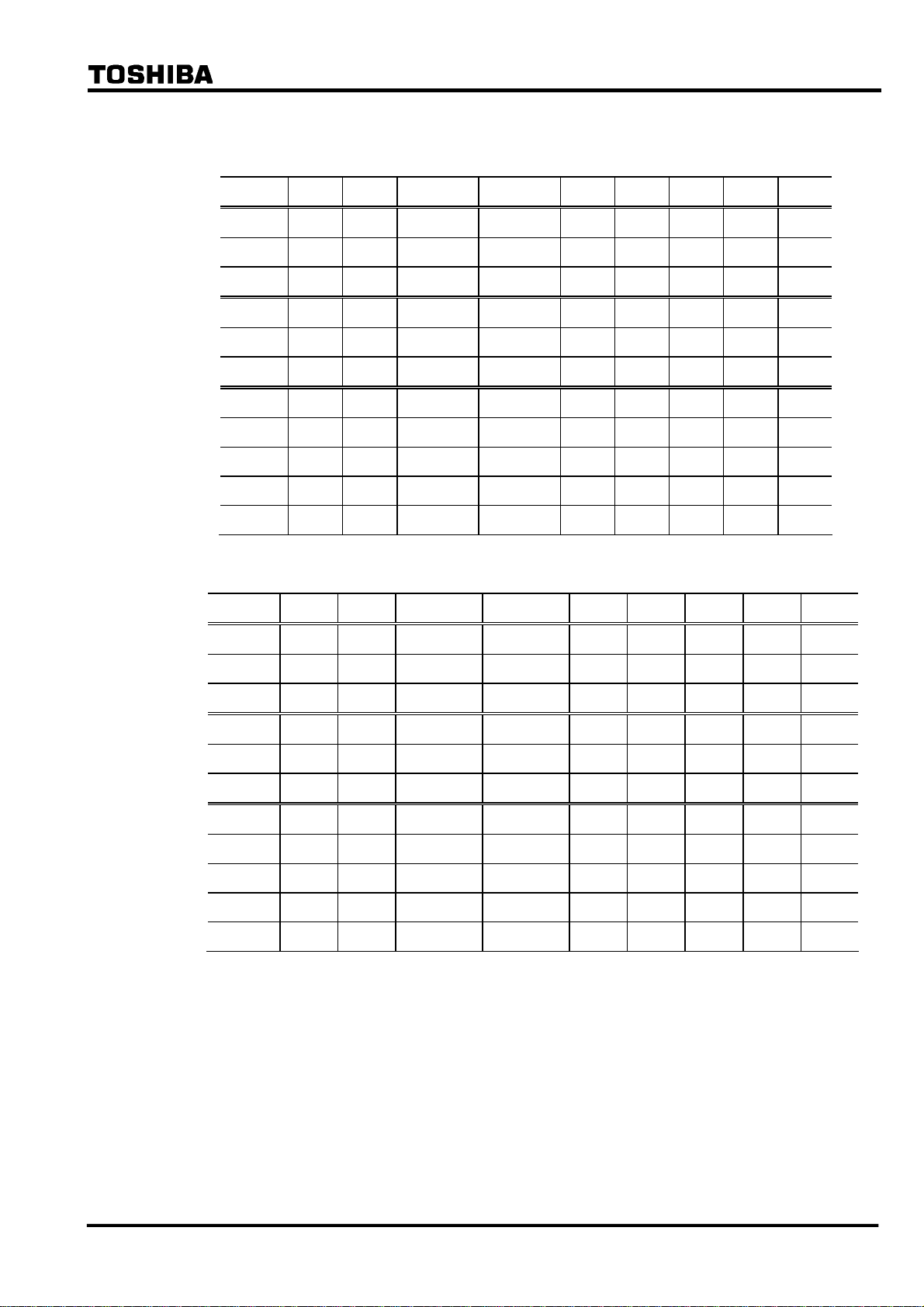
Table 1.1 GRL100 Models
6 F 2 S 0 8 3 5
(a) Two-terminal line application
Model 101B 102B 201B, 204B 202B, 206B 301B 302B 401B 501B 503B
DIF x x x x x x x x x
BU x x x x x x x x x
THM x x x x x x
ARC 1CB 1CB 2CB 2CB 1CB 2CB 2CB
FD x x x
TFC x
DIFG x x x x x x x
CCC x x x x x x x
BF x x x x x x x
OST x x x x x x x
FL x x x x x x x
(b) Three-terminal line application / Dual communication for two-terminal line application
Model 111B 112B 211B, 214B 212B, 216B 311B 312B 411B 511B 513B
DIF x x x x x x x x x
BU x x x x x x x x x
THM x x x x x x
ARC 1CB 1CB 2CB 2CB 1CB 2CB 2CB
FD x x x
TFC x
DIFG x x x x x x x
CCC x x x x x x x
BF x x x x x x x
OST x x x x x x x
FL x x x x x x x
Legend DIF: Segregated-phase current differential protection
BU: Overcurrent backup protection
THM: Thermal overload protection
ARC: Autoreclose
FD: Fault detector
TFC: Through fault current countermeasure
DIFG: Zero-phase current differential protection
CCC: Charging current compensation
BF: Breaker failure protection
OST: Out-of-step protection
FL: Fault locator
⎯ 11 ⎯
2. Application Notes
GRL100 is applicable to telecommunication system s which employ dedicated optical fibre, 64 kbit/s
multiplexed communication channels or microwave links
communication mode settings:
• A-MODE: applied when the remote terminal relay(s) is an old version of GRL100,
namely the following models.
GRL100-101A/102A/201A/202A/301A/302A/ 401A/501A/503A
GRL100-111A/112A/211A/212A/311A/312A/411A/511A/513A
GRL100-201N
• B-MODE: standard operating model which provides relay address monitoring function
and customisation of transmission data. (default)
• GPS-MODE: performs synchronised sampling using GPS. (This mode is suited to
applications where the differential relays communicate over modern switched
telecommunication networks such as Synchronous Digital Hierarchy (SDH), etc.)
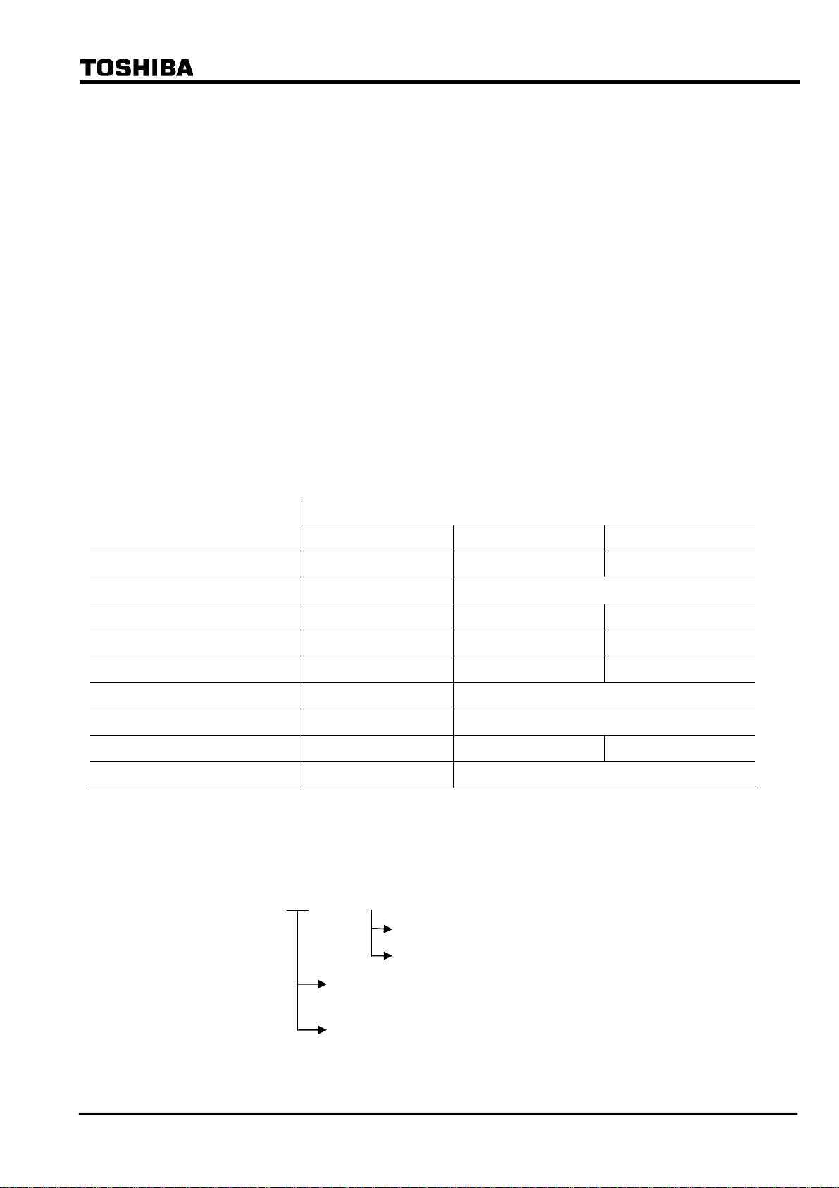
Table 2.1 shows available functions of each mode. The details of functions are described later.
6 F 2 S 0 8 3 5
and provided with the following three
Table 2.1 Communication Mode and Available Function
Function
GPS-based synchronisation
Relay address monitoring (RYIDSV)
Dual communication
Remote differential trip (RDIF)
Through fault current measure (TFC)
Open terminal detection (OTD)
Multi-phase autoreclosing (MPAR)
Simultaneous fault signal (FG)
Transfer signal 2 bit (set by PLC function) 2 bit (set by PLC function.)
× ×
× (for model 503B, 513B)
× × (set RYIDSV to Off if applied.)
× × (The alternative of RYIDSV or MPAR)
× × ×
A-MODE B-MODE GPS-MODE
Communication Mode [COMMODE]
× (The alternative of RYIDSV or MPAR)
× ×
GPS-MODE can be applied if the relay is provided with a GPS interface.
One of these modes can be selected by the scheme switch [COMMODE]. The default setting is
“B-MODE”.
(Relay Type and Model)
×
(eg.) GRL100 - ∗∗∗B - 13 - 1∗
0: without GPS I/F
1: with GPS I/F (Model 503/513 are not available)
503/513: with through fault current measure
(available for A-MODE only)
others: without through fault current measure
For details of relay models and their functions, see Table 1.1 and Appendix S.
⎯ 12 ⎯

2.1 Protection Schemes
The GRL100 provides the following protection schemes (Appendix A shows block diagrams of the
GRL100 series):
• Segregated-phase current differential protection
• Zero-phase current differential protection
• Remote differential trip function
• Stub protection
• Overcurrent backup protection
• Thermal overload protection
• Out-of-step protection
• Breaker failure protection
• Transfer trip protection
Zero-phase current differential protection enables sensitive protection for high-impedance earth
faults.
6 F 2 S 0 8 3 5
Overcurrent backup protection provides both inverse time overcurrent and definite time overcurrent
protection for phase faults and earth faults.
Out-of-step protection performs phase comparison of the local and remote voltages and operates
only when the out-of-step loci cross the protected line.
Furthermore, the GRL100 incorporates autoreclose functions for one or two breaker systems,
through-current fault countermeasures for two breaker systems, charging current compensation for
cable or long-distance lines and fault location. The autoreclose mode can be selected from
single-phase, three-phase, single- and three-phase and multi-phase modes.
The GRL100 can enhance security by attaching fault detectors such as check relays with circuits that
are independent from other circuits.
The GRL100 utilises with the microwave or fibre optic digital telecommunication systems to
transmit instantaneous current values sampled synchronously at each terminal.
⎯ 13 ⎯
(
2.2 Current Differential Protection
2.2.1 Operation of Current Differential Protection
Current differential protection compares the currents flowing into and out of the protected line.
The difference of the currents, that is, the differential current, is almost zero when a fault is
external or there is no fault, and is equal to the fault current when the fault is internal. The
differential protection operates when the difference of the currents exceeds a set value.
The GRL100 relay installed at each line terminal samples the local currents every 7.5 electrical
degrees and transmits the current data to other terminals every four samples via the
telecommunication system. The GRL100 performs master/master type current differential
protection using the current data from all terminals.
As synchronized sampling of all terminals is performed in the GRL100, the current data are the
instantaneous values sampled simultaneously at each terminal. Therefore, the differential current
can be easily calculated by summing the local and remote current data with the identical
sampling address. Thus, compensation of transmission delay time is not required.
The GRL100 utilises the individual three phase currents and residual current to perform
segregated-phase and zero-phase current differential protection.
6 F 2 S 0 8 3 5
2.2.2 Segregated-phase Current Differential Protection
The segregated-phase differential protection transmits the three phase currents to the remote
terminal, calculates the individual differential currents and detects both phase-to-phase and
phase-to-earth faults on a per phase basis.
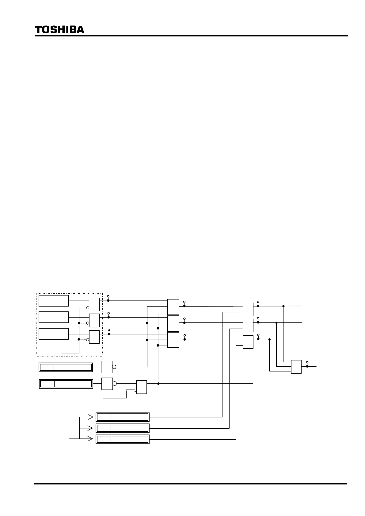
Figure 2.2.2.1 shows the scheme logic of the segregated-phase current differential protection.
Output signals of differential elements DIF-A, -B and -C can perform instantaneous tripping of
the breaker on a per phase basis and start the incorporated autoreclose function.
Note: For the symbols used in the scheme logic, see Appendix L.
DIF-A
DIF-B
DIF-C
Communication
failure
DIF_BLOCK
1585
CRT_BLOCK
1544
TELEPROTEC TION OFF
from IEC103 command)
&
&
&
1
1
41
42
43
&
82: DIF-A_TRIP
&
83: DIF-B_TRIP
&
84: DIF-C_TRIP
&
401
&
402
&
403
&
43C ON
DIF.FS-A_TP
DIF.FS-B_TP
DIF.FS-C_TP
400
≥1
DIF.FS_TRIP
DIF-A_FS
1616
DIF-B_FS
1617
DIF.FS_OP
1618
DIF-C_FS
Figure 2.2.2.1 Scheme Logic of Segregated-phase Current Differential Protection
⎯ 14 ⎯

6 F 2 S 0 8 3 5
Tripping output signals can be blocked by the PLC command DIF_BLOCK and CRT_BLOCK.
The output signals of DIF-A, DIF-B and DIF-C are also blocked when a communication circuit
failure is detected by the data error check, sampling synchronism check or interruption of the
receive signals. For DIF-A_FS, DIF-B_FS and DIF-C_FS signals, see Section 2.2.4.
The differential elements DIF have a percentage restraining characteristic with weak restraint in
the small current region and strong restraint in the large current region, to cope with CT
saturation. (For details of the characteristic, see Section 2.11.)
Erroneous current data may be transmitted from the remote terminal when the remote relay is
out-of-service for testing or other purposes. To prevent false operation in this case, the relay sets
the receiving current data to zero in the differential current calculation upon detecting that the
remote terminal is out-of-service.
If the relay is applied to a three-terminal line, the zero setting is performed only for the current
data received from an out-of-service terminal.
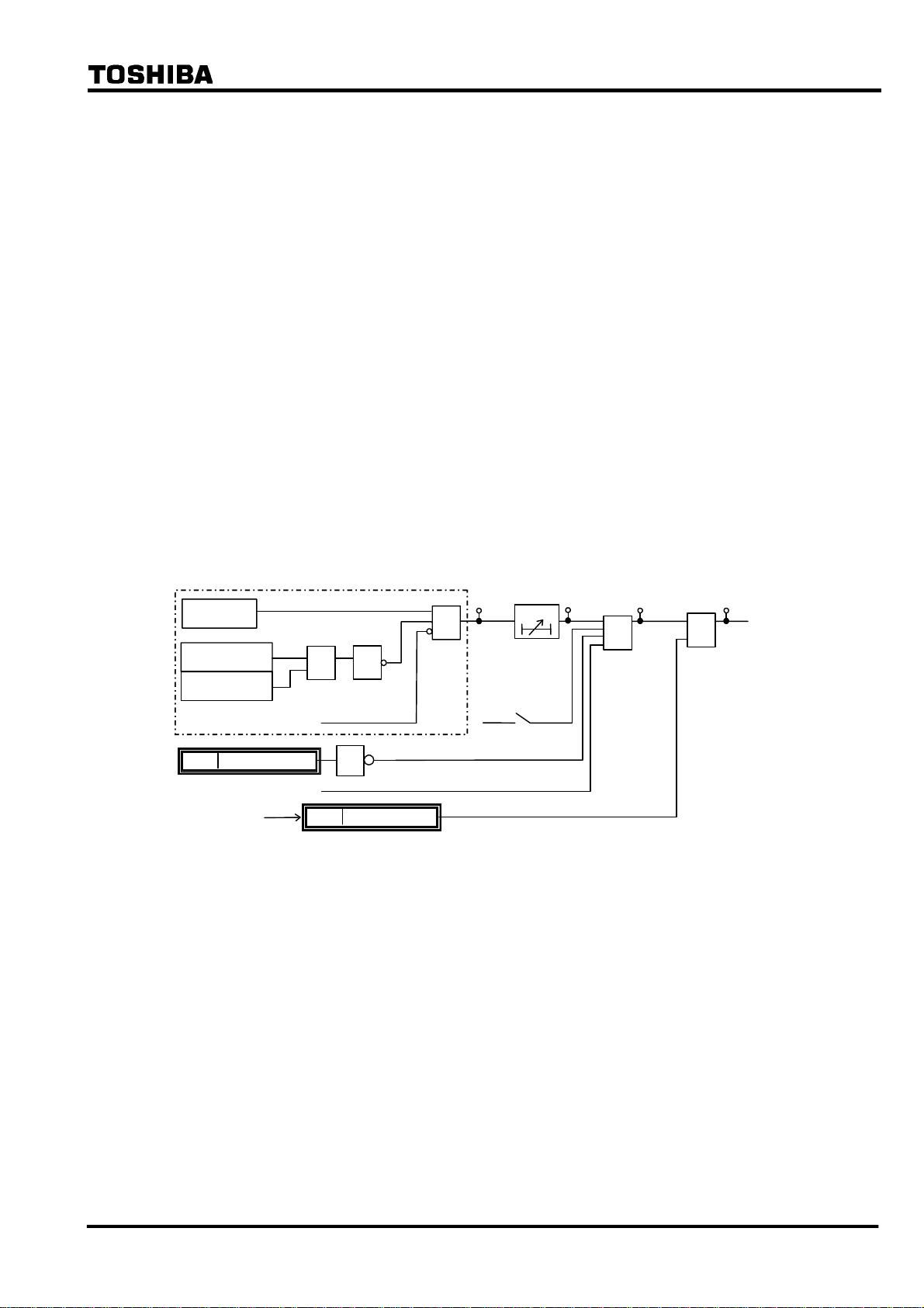
Figure 2.2.2.2 shows the remote terminal out-of-service detection logic. The local terminal
detects that the remote terminal is out-of-service by receiving a signal LOCAL TEST which is
transmitted when the scheme switch [L. TEST] is set to "ON" at the terminal under test. As an
alternative means, the local terminal can detect it by using the circuit breaker and disconnector
status signal CBDS-A, B and C transmitted from the remote out-of-service terminal. The signal
CBDS-A is "1" when both the circuit breaker and disconnector are closed. Thus, out-of-service
is detected when either the circuit breaker or disconnector is open in all three phases.
Zero setting of the receive current data is also performed at the terminal under test. If the scheme
switch [L. TEST] is set to "ON" or the signal R.DATA_ZERO is input by PLC, all the receive
current data transmitted from the in-service terminal is set to zero and this facilitates the local
testing. The zero setting of the receive current data is not performed by the alternative way as
mentioned above.
The out-of-service detection logic can be blocked by the scheme switch [OTD].
Receiving
signal from
Remote
Terminal 1
(∗) Out-of-service detection logic for the remote 2 is same as above.
R.DATA_ZERO
1623
LOCAL_TEST1
CBDS-A
CBDS-B
CBDS-C
[OTD]
(+)
"ON"
≥1
≥1
1
1
(+)
&
[Open1]
"ON"
≥1
≥1
REM1_IN_SRV: Remote 1 i n-servic e
REM1_OFF_SRV: Remote 1 out-of-service
REM1_NON_USE: Rem ote 1 not used
Figure 2.2.2.2 Out-of-Service Detection Logic
Note: When a communication circuit is disconnected or communication circuit failure occurs, do
not close the circuit breaker. When closing it, make sure that the DIF element is blocked.
(Otherwise, it may cause malfunction.)
207
REM1_IN_SRV
208
REM1_OFF_SRV
209
1
REM1_NON_USE
2.2.3 Zero-phase Current Differential Protection
The GRL100 provides sensitive protection for high-impedance earth faults by employing
zero-phase current differential protection. For more sensitive protection, residual current is
introduced through an auxiliary CT in the residual circuit instead of deriving the zero-phase
current from the three phase currents.
⎯ 15 ⎯
6 F 2 S 0 8 3 5
The zero-phase current differential element has a percentage restraining characteristic with weak
restraint. For details of the characteristic, see Section 2.11.
The scheme logic is shown in Figure 2.2.3.1. The output signal of the differential element DIFG
performs time-delayed three-phase tripping of the circuit breaker with the tripping output signal
DIFG.FS_TRIP. DIFG.FS_TRIP can start the incorporated autoreclose function when the
scheme switch [ARC-DIFG] is set to "ON".
Tripping output signal can be blocked by the PLC command DIFG_BLOCK and CRT_BLOCK.
The output signal is also blocked when a communication circuit failure is detected by data error
check, sampling synchronism check or interruption of the receive signals. For DIFG_FS signal,
see Section 2.2.4.
Since the DIFG is used for high-impedance earth fault protection, the DIFG output signal is
blocked when zero-phase current is large as shown in the following equation:
Σ ⎜I
01⎜ ≥ 2 pu or Σ ⎜I02⎜ ≥ 2 pu
where,
Σ ⎜I
Σ ⎜I
01⎜: Scalar summation of zero-phase current at local terminal relay
02⎜: Scalar summation of zero-phase current at remote terminal relay
pu: per unit value
In GPS-mode setting and backup mode (refer to 2.2.7.2), DIFG is blocked.
DIFG
Σ⏐I01⏐≥2PU
Σ⏐I02⏐≥2PU
Communication failure
DIFG_BLOCK
1586
43C ON
DIFG.FS_OP
Figure 2.2.3.1 Scheme Logic of Zero-phase Current Differential Protection
≥1
1619
1
1
DIFG_FS
TDIFG
44
+
t 0
0.00-10.00s
[DIFG]
"ON"
&
85
DIFG_TRIP
86
&
404
&
DIFG.FS_TRIP
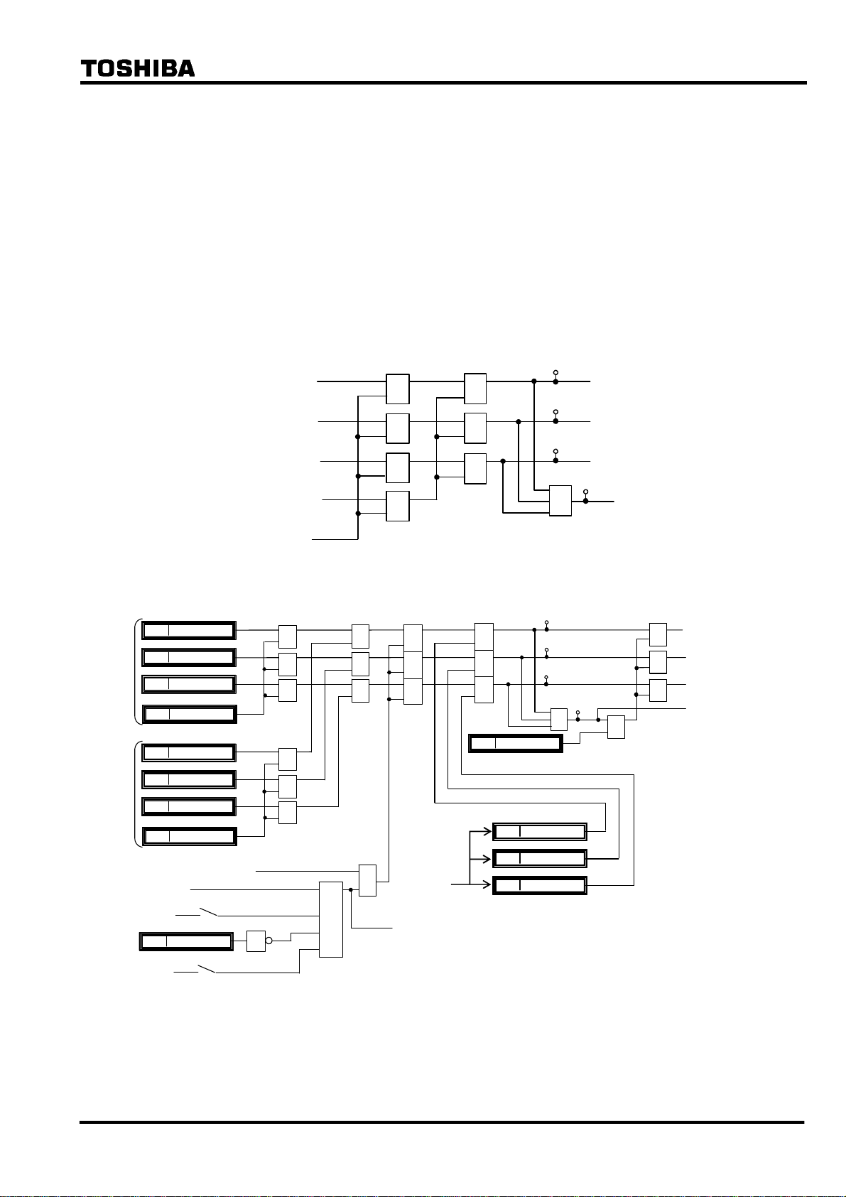
2.2.4 Fail-safe Function
GRL100 provides OC1, OCD and EFD elements. These are used for fail-safe to prevent
unnecessary operation caused by error data in communication failure. OC1 is phase overcurrent
element and its sensitivity can be set. OCD is phase current change detection element, and EFD
is zero-sequence current change detection element. Both of the OCD and EFD sensitivities are
fixed. The scheme logic is shown in Figure 2.2.4.1.
The outputs of DIF.FS_OP and DIFG.FS_OP signals are connected to DIF-A_FS, DIF-B_FS,
DIF-C_FS and DIFG_FS respectively by PLC function. These are connected at the default
setting.
The fail-safe functions are disabled by [DIF-FS] and [DIFG-FS] switches. In the [DIF-FS], OC1
or OCD or both elements can be selected. If these switches are set to “OFF”, the signals of
DIF.FS_OP and DIFG.FS_OP are “1” and the fail-safe is disabled.
⎯ 16 ⎯
6 F 2 S 0 8 3 5
+
+
OC1-A
OC1-B
OC1-C
OCD-A
OCD-B
OCD-C
[DIF-FS]
EFD
[DIFG-FS]
"OC"
OCD"
"
BOTH"
"
OFF"
"
"ON"
409
≥
1
&
&
&
&
&
&
≥1
≥
1
&
DIF.FS-A_OP
410
≥
1
DIF.FS-B_OP
411
≥
1
DIF.FS-C_OP
≥
1
DIFG.FS_OP
412
408
≥
1
DIF.FS_OP
DIFG_FS
(see Fig. 2.2.3.1.)
DIF-A_FS
DIF-B_FS
DIF-C_FS
(see Fig. 2.2.2.1.)
OFF"
"
Figure 2.2.4.1 Fail-safe Logic
2.2.5 Remote Differential Trip
Note: This function is available only when the three-terminal protection is applied by
setting the scheme switch [TERM] to “3-TERM”. In the case of A-MODE setting,
this function is not available.
When one of the telecommunication channels fails, the terminal using the failed channel is
disabled from performing current differential protection, as a result of the failure being detected
through by the telecommunication channel monitoring.
GRL100
GRL100
GRL100
Figure 2.2.5.1 Protection Disabled Terminal with Channel Failure
The remote differential trip (RDIF) function enables the disabled terminal to trip by receiving a
trip command from the sound terminal, which continues to perform current differential
protection.
⎯ 17 ⎯
6 F 2 S 0 8 3 5
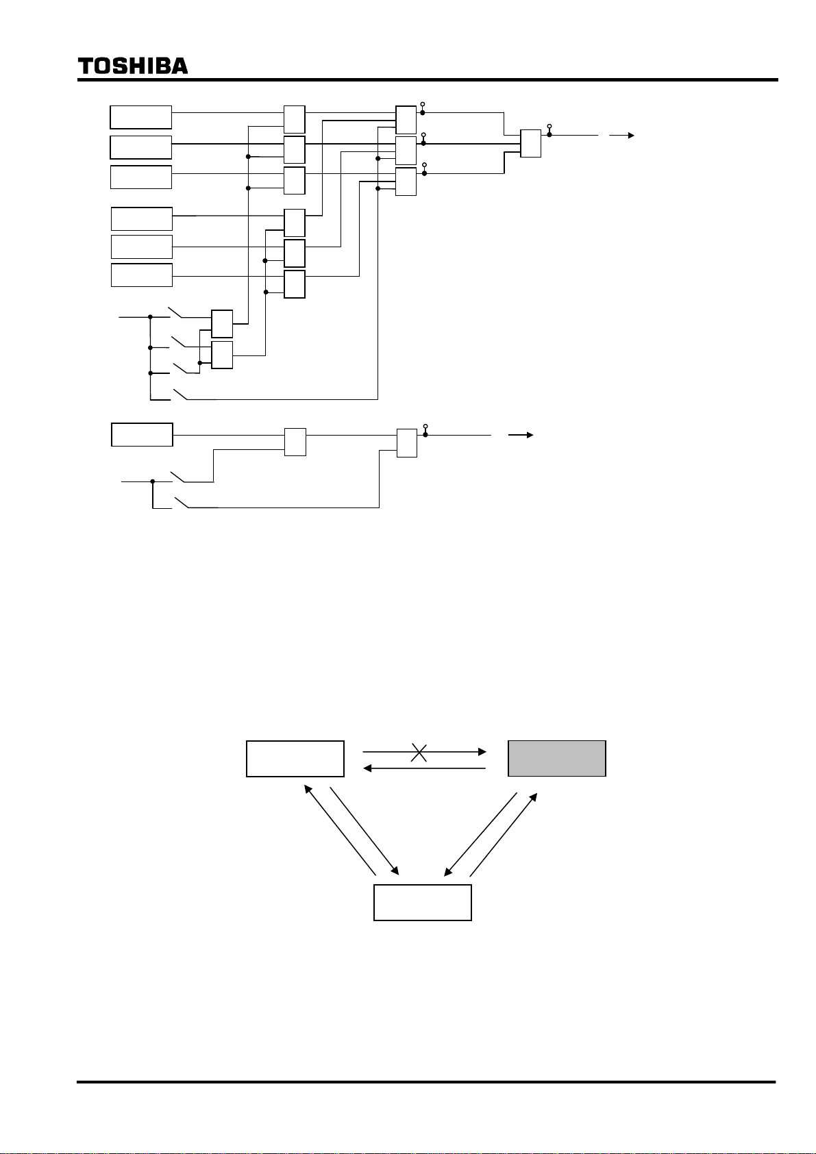
Figure 2.2.5.2(a) and (b) show the RDIF scheme logic at RDIF command sending terminal (=
sound terminal) and command receiving terminal (= disabled terminal). The sound terminal
sends the command when the tripping signals RDIF-A-S, RDIF-B-S, RDIF-C-S or RDIF-S are
output locally and the scheme switches [RDIF] and [TERM] are set to “ON” and “3-TERM”
respectively. The RDIF command is sent to the remote terminal via the 64kb/s digital link
together with other data and signals.
The receiving terminal outputs a local three-phase trip signal RDIF-TRIP under the conditions
that when the command RDIF1 or RDIF2 is received from either of the remote terminals, local
differential protection does not operate, the scheme switches [RDIF] and [TERM] are set to
“ON” and “3-TERM” respectively and no communication channel failure exists in the channel
which received the RDIF command.
When the RDIF function is applied, the command sending signals and receiving signals must be
assigned by PLC function.
DIF-A_TRIP
DIF-B_TRIP
DIF-C_TRIP
DIF-G_TRIP
&
&
&
≥1
≥1
≥1
&
451
452
453
≥1
RDIF-A-S
RDIF-B-S
RDIF-C-S
454
RDIF-S
Receiving
signal from
Remote
Terminal 1
Receiving
signal from
Remote
Terminal 2
RDIF-A-R1
1684
RDIF-B-R1
1685
RDIF-C-R1
1686
RDIF-R1
1687
RDIF-A-R2
1716
RDIF-B-R2
1717
RDIF-C-R2
1718
RDIF-R2
1719
DIF elements not operated
43C ON
1598
[TERM]
+
“3-TERM” &
RDIF_BLOCK
[RDIF]
+
“ON”
RDIF_ON
≥1
≥1
≥1
≥1
≥1
≥1
1
(a) Sending terminal
≥1
≥1
≥1
&
&
&
&
1649
DIF.FS_OP
RDIF_ON
(b) Receiving Terminal
&
&
&
RDIF_3PTP
1624
1625
1626
456
457
458
≥1
RDIF-A_FS
RDIF-B_FS
RDIF-C_FS
RD.FS-A_ TRIP
RD.FS-B_ TRIP
RD.FS-C_ TRIP
455
&
≥1
≥1
≥1
RD.FS-A TP
RD.FS-B TP
RD.FS-C TP
RD.FS_TRIP
Figure 2.2.5.2 Remote Differential Trip
⎯ 18 ⎯

6 F 2 S 0 8 3 5
2.2.6 Transmission Data
The following data are transmitted to the remote terminal via the 64kb/s digital link. The data
depends on the communication mode and whether a function is used or not. The details are
shown in Appendix N.
A-phase current
B-phase current
C-phase current
Residual current
Positive sequence voltage
A-phase differential element output signal
B-phase differential element output signal
C-phase differential element output signal
A-phase breaker and disconnector status
B-phase breaker and disconnector status
C-phase breaker and disconnector status
Scheme switch [LOCAL TEST] status
Scheme switch [TFC] status
Reclose block command
Sampling synchronization control signal
Synchronized test trigger signal
User configurable data
Current and voltage data are instantaneous values which are sampled every 30 electrical degrees
(12 times per cycle) and consist of eleven data bits and one sign bit. This data is transmitted
every sample to the remote terminal.
Three differential element outputs and the transfer trip command are related to remote terminal
tripping and are transmitted every sampling interval.
Other data is transmitted once every power cycle.
The data transmission format and user configurable data are also shown in Appendix N.
A synchronized test trigger signal is used to test the differential protection simultaneously at all
terminals. For details, see Section 6.5.3.
In addition to the above data, cyclic redundancy check bits and fixed check bits are transmitted to
monitor the communication channel. If a channel failure is detected at the local terminal, all the
local and remote current and voltage data at that instant are set to zero and outputs of the
differential protection and out-of-step protection are blocked, and these protections of remote
terminal are also blocked because the channel failure is also detected at the remote terminal.
2.2.7 Synchronized Sampling
The GRL100 performs synchronized simultaneous sampling at all terminals of the protected
line. Two methods are applied for the sampling synchronization; intra-system synchronization
and GPS-based synchronization. The former is applied to communication modes A-MODE and
⎯ 19 ⎯
6 F 2 S 0 8 3 5
B-MODE, and the latter is applied to GPS-MODE.
The intra-system synchronization keeps the sampling timing error between the terminals within
±10μs or ±20μs and the GPS-based system keeps it within ±5μs or ±10μs for two- or
three-terminal applications.
In both methods, the sampling synchronization is realized through timing synchronization
control and sampling address synchronization control. These controls are performed once every
two power cycles.
2.2.7.1 Intra-system Synchronized Sampling for A-MODE and B-MODE
The synchronized sampling is realized using sampling synchronization control signals
transmitted to other terminals together with the power system data. This synchronized sampling
requires neither an external reference clock nor synchronization of the internal clocks of the
relays at different terminals. The transmission delay of the channel is corrected automatically.
Timing synchronization
One of the terminals is selected as the time reference terminal and set as the master terminal. The
other terminal is set as the slave terminal. The scheme switch [SP.SYN] is used for the settings.
Note: The master and slave terminals are set only for the convenience of the sampling timing
synchronization. The GRL100s at all terminals perform identical protection functions and
operate simultaneously.
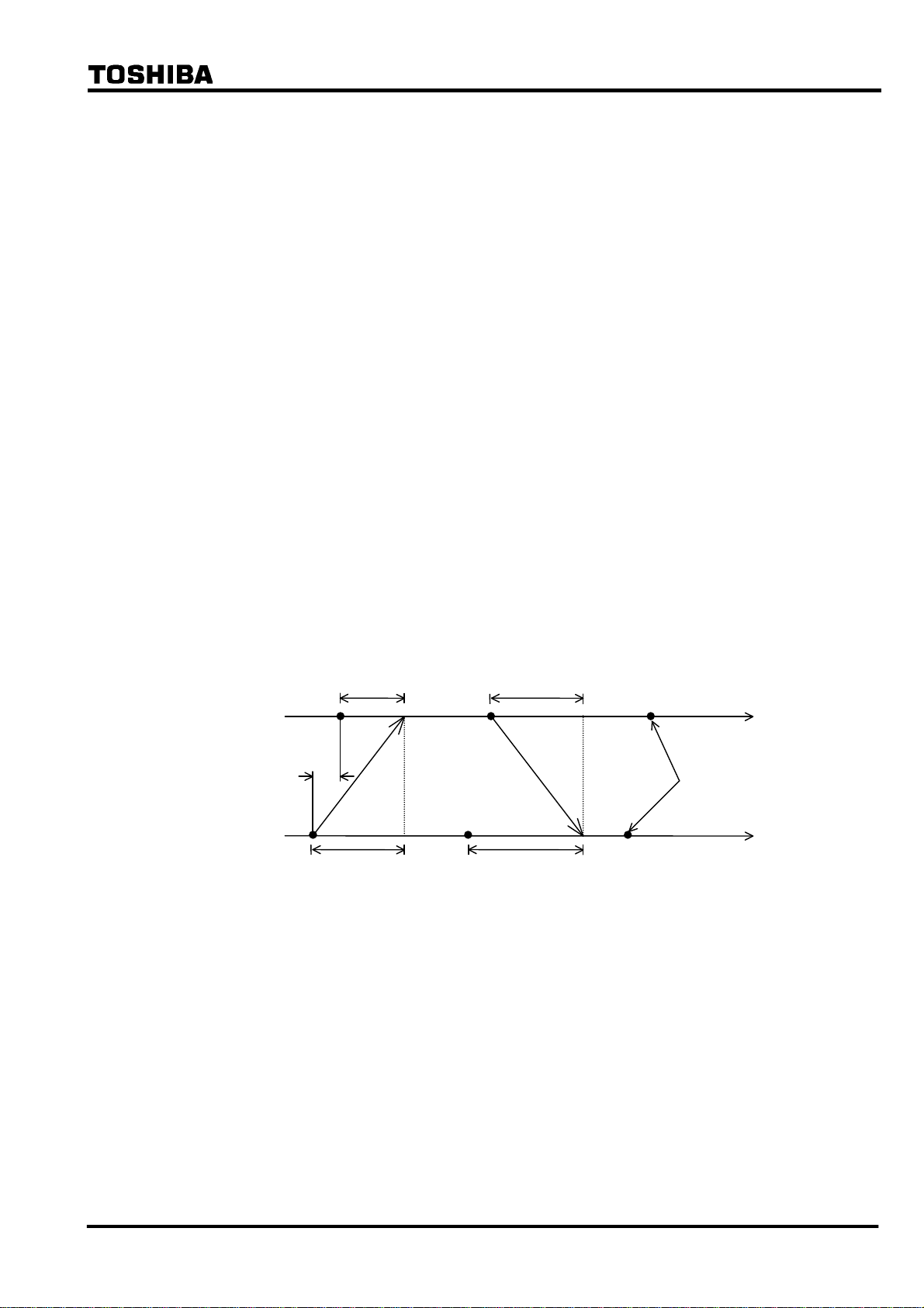
To perform timing synchronization for the slave terminal, the sampling time difference between
master and slave terminals is measured. The measurement principle of the sampling time
difference ΔT is indicated in Figure 2.2.7.1. The master terminal and slave terminal perform
their own sampling and send a signal that becomes the timing reference for the other terminal.
Master
terminal
Slave
terminal
TM
ΔT
Td1
Figure 2.2.7.1 Timing Synchronization
T
d2
t
Sampling
timing
t
T
F
Each terminal measures the time TM and TF from its own sampling instant to the arrival of the
signal from the other terminal. As is evident from the figure, the times TM and TF can be
obtained by equation (1) and (2) where Td1 and Td2 are the transmission delay of the channel in
each direction. The sampling time difference ΔT can be obtained from the resulting equation (3).
TM = Td1 − ΔT (1)
TF = Td2 + ΔT (2)
ΔT = {(TF − TM) + (Td1 − Td2)}/2 (3)
The slave terminal advances or retards its sampling timing based on the time ΔT calculated from
equation (3), thereby reducing the sampling time difference with the master terminal to zero.
This adjustment is performed by varying the interval of the sampling pulse generated by an
⎯ 20 ⎯
6 F 2 S 0 8 3 5
oscillator in the slave terminal.
The difference of the transmission delay time Tdd (= Td1 − Td2) is set to zero when sending and
receiving take the same route and exhibit equal delays. When the route is separate and the
sending and receiving delays are different, Tdd must be set at each terminal to be equal to the
sending delay time minus the receiving delay time. The maximum Tdd that can be set is 10ms.
(For setting, see Section 4.2.6.7. The setting elements of transmission delay time difference are
TCDT1 and TCDT2.)
The time TM measured at the master terminal is sent to the slave terminal together with the
current data and is used to calculate the ΔT.
The permissible maximum transmission delay time of the channel is 10ms.
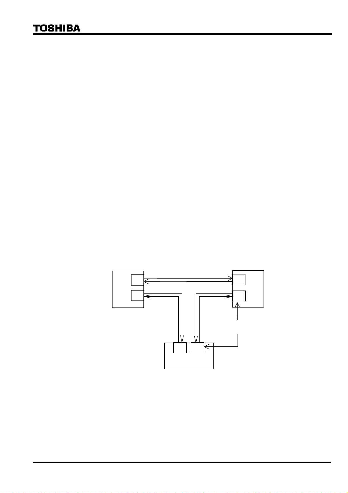
In case of the three-terminal line application, the communication ports of the GRL100 are
interlinked with each other as shown in Figure 2.2.7.2, that is, port CH1 of one terminal and port
CH2 of the other terminal are interlinked. For the setup of the communication system, see
Section 2.12.3.
When terminal A is set as the master terminal by the scheme switch [SP.SYN], the
synchronization control is performed between terminals A and B, and terminals B and C. The
terminal B follows the terminal A and the terminal C follows the terminal B. The slave terminals
perform the follow-up control at their communication port CH2.
When the master terminal is out-of-service in A-MODE, the slave terminal that is interlinked
with port 1 of the master terminal takes the master terminal function. In the case shown in Figure
2.2.7.2, terminal B takes the master terminal function when the master terminal A is
out-of-service. In B-MODE and GPS-MODE, even if the master terminal is out-of-service, the
master terminal is not changed. If DC power supply of the out-of-service terminal is “OFF”,
differential elements at all terminals are blocked. Therefore, the [TERM] setting change from
“3TERM” to “2TERM” is required.
Terminal A
GRL100
CH1
CH2
Master
CH1 CH2
GRL100
Terminal C
Slave
Terminal B
CH2
GRL100
CH1
Slave
Communication
port
Figure 2.2.7.2 Communication Link in Three-terminal Line
Sampling address synchronization
The principle of sampling address synchronization control is indicated in Figure 2.2.7.3. After
time synchronization has been established, the slave terminal measures the time from sending its
own timing reference signal until it returns from the master terminal. The transmission delay
time Td1 from slave to master terminal can be calculated from equation (4).
⎯ 21 ⎯

6 F 2 S 0 8 3 5
Td = ({To − (T − TM)}/2 + Tdd)/2 (4)
The calculated transmission delay time Td1 is divided by the sampling interval T. The mantissa
is truncated and the quotient is expressed as an integer. If the integer is set to P, the reception at
the slave terminal of the signal sent from the master terminal occurs at P sampling intervals from
the transmission. Accordingly, by performing control so that the sampling address of the slave
terminal equals integer P when the sampling address = 0 signal is received from the master
terminal, the sampling address of the slave terminal can be made the same as the master term inal.
T
t
Master
terminal
T
M
Slave
terminal
T
F
T
d1
T
O
T
d2
t
Figure 2.2.7.3 Sampling Address Synchronization
2.2.7.2 GPS-based Synchronized Sampling for GPS-MODE
The relays at all terminals simultaneously receive the GPS clock signal once every second.
Figure 2.2.7.4 shows the GPS-based synchronized sampling circuit at one terminal. The GPS
clock signal is received by the GPS receiver HHGP1 and input to a time difference measurement
circuit in the GRL100. The circuit measures the time difference ΔT between the GPS clock and
the internal clock generated from the crystal oscillator. The oscillator is controlled to
synchronize with the GPS clock using the measured ΔT and outputs 2,400 Hz (50Hz rating)
sampling signals to the current sampling circuit (analog to digital converter).
GPS
Line
GRL100
GPS receiver
HHGP1
Time
difference
measurement
ΔT
Crystal
oscillator
Lead/lag control
Analog/digital
converter
Synchronous control
Figure 2.2.7.4 GPS Clock-based Sampling
Timing synchronization
When the GPS signal is received normally at every line terminal, the GRL100 performs
synchronized sampling based on the received clock signal. The GRL100 can provide a backup
synchronization system if the GPS signal is interrupted at one or more terminals, and perform
synchronized sampling without any external reference clock. The backup system becomes valid
by setting the scheme switch [GPSBAK] to "ON".
⎯ 22 ⎯

6 F 2 S 0 8 3 5
In the backup modes, the percentage restraint in the small current region can be increased from
the normal 16.7% ((1/6)Ir in Figure 2.9.10.1) in accordance with the PDTD setting which is the
probable transmission delay time difference between send and receive channels.
Backup modes, Mode 1, 2A and 2B are initialised when the backup system is set valid.
If the GPS signal interruption occurs when the backup is set invalid, the sampling runs based on
the local clock. When the arrival time of the remote signal measured from local sampling instant
deviates from a nominal time, the protection is blocked.
Mode 0: When the GPS signal is received normally, the sampling is performed synchronizing
with the received clock signal thus realizing synchronized sampling at all terminals. Difference
of the transmission delay time for the channel in each direction and fluctuation of the delay time
can be permitted.
The GRL100 performs the protection based on the nominal current differential characteristics.
When the GPS signal has interrupted for more than ten seconds at any of the terminals, the mode
changes to Mode 1 at all terminals.
Mode 1: The terminal which loses its GPS signal first functions as the slave terminal. If all
terminals lose their signals simultaneously, then the scheme switch [SP.SYN] setting determines
which terminal functions as the slave or master. The slave terminal adjusts the local sampling
timing to synchronize the sampling with other terminal which is receiving the GPS signal
regularly or with the master terminal.
Note: When two terminals are receiving the GPS signal regularly, the slave terminal
synchronizes with the terminal that is interlinked with port 2 of the slave terminal.
When the GPS signal has been restored, the mode shifts from Mode 1 back to Mode 0.
If, during Mode 1 operation, a failure occurs in the communication system, the sampling timing
adjustment is disabled and each terminal runs free. If the free running continues over the time
determined by the PDTD setting or the apparent phase difference exceeds the value determined
by the PDTD setting, the mode shifts from Mode 1 to Mode 2A at all terminals.
Mode 2A: In this mode, the intra-system synchronization described in 2.2.7.1 is applied
assuming that the transmission delay time for the channel in each direction is identical.
Fluctuation of the delay time can be permitted.
The current differential protection is blocked in this mode.
When the GPS signal has been restored, the mode shifts from Mode 2A to Mode 0.
If the GPS signal interruption occurs a set period following energisation of the relay power
supply or the mode returned to Mode 0 from Mode 1, 2A or 2B, then the transmission delay time
measurement will not be completed in Mode 0, and the mode changes to Mode 2A.
When the apparent current phase difference has stayed within the value determined by the PDTD
setting, the scheme switch [AUTO2B] for automatic mode change is set to "ON" and [TERM] is
set to "2TERM", the mode changes from Mode 2A to Mode 2B at both terminals.
The mode can be changed to Mode 2B manually through a binary input signal "Mode 2B
initiation" or user interface. Before this operation, it must be checked that the transmission delay
time difference between send and receive terminals is less than the PDTD setting and the SYNC
ALARM LED is off. If these conditions are not satisfied, the operation may cause a false
tripping.
Note: The mode change with the binary input signal is performed by either way:
• If the binary input contact is such as to be open when the relay is in service, set
the BI to "Inv" (inverted). The mode changes when the contact is closed more
⎯ 23 ⎯
θ
6 F 2 S 0 8 3 5
than 2 seconds and then open.
• If the binary input contact is such as to be closed when the relay is in service, set
the BI to "Norm" (normal). The mode changes when the contact is open more
than 2 seconds and then closed.
For the BISW4, see Section 3.2.1.
In the three-terminal application, the mode change to Mode 2B is available even
when one of the three communication routes is failed.
Mode 2B: The same intra-system synchronization as in Mode 2A is applied.
When the GPS signal has been restored, the mode shifts from Mode 2B to Mode 0.
If a failure occurs in the communication system, the sampling timing adjustment is disabled and
each terminal runs free.
The mode shifts from Mode 2B to Mode 2A, when the apparent load current phase difference
exceeds the value determined by the PDTD setting for pre-determined time.
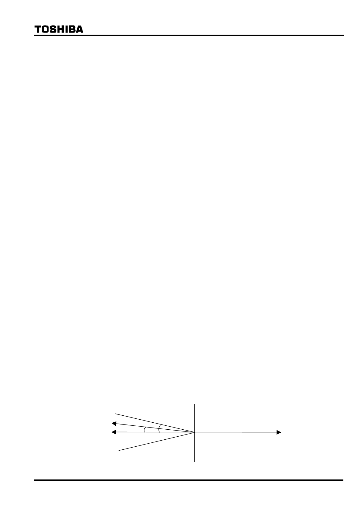
Checking the current phase difference (For two-terminal application setting only)
The current phase difference is checked using the following equations:
I
1A ⋅ cos θ < 0
1A ⋅ I1B sin θ < I1A ⋅ I1B sin θs
I
I
1A > OCCHK
I
1B > OCCHK
Where,
I
1A = Positive sequence component of load current at local terminal
1B = Positive sequence component of load current at remote terminal
I
θ = Phase difference of I
1B from - I1A
θs = Critical phase difference
= CHKθ‐HYSθ
CHKθ =
PDTD(μs)
2
360°
×
20000(μs)
+ 8.5°
HYSθ = Margin of phase difference checking
OCCHK = Minimum current for phase difference check
If the magnitude of I
1A and I1B exceed the setting and the conditions for both equations above are
established, then the sampling is regarded to be synchronized.
If the current phase difference exceeds a set value, the "SYNC ALARM" LED on the front panel
is lit.
Checking the current phase difference is enabled by setting the scheme switches [TERM] to
"2TERM" and [SRCθ] to "I".
I1B
-I1A
s
θ
I1A
Figure 2.2.7.5 Current Phase Difference Check
⎯ 24 ⎯
6 F 2 S 0 8 3 5
Sampling address synchronization
The same method as described in section 2.2.7.1 is employed in Mode 0 and Mode 2A where the
sampling synchronization must be established. It is not employed in Mode 1 and 2B because the
sampling address synchronization has already been established in the previous mode.
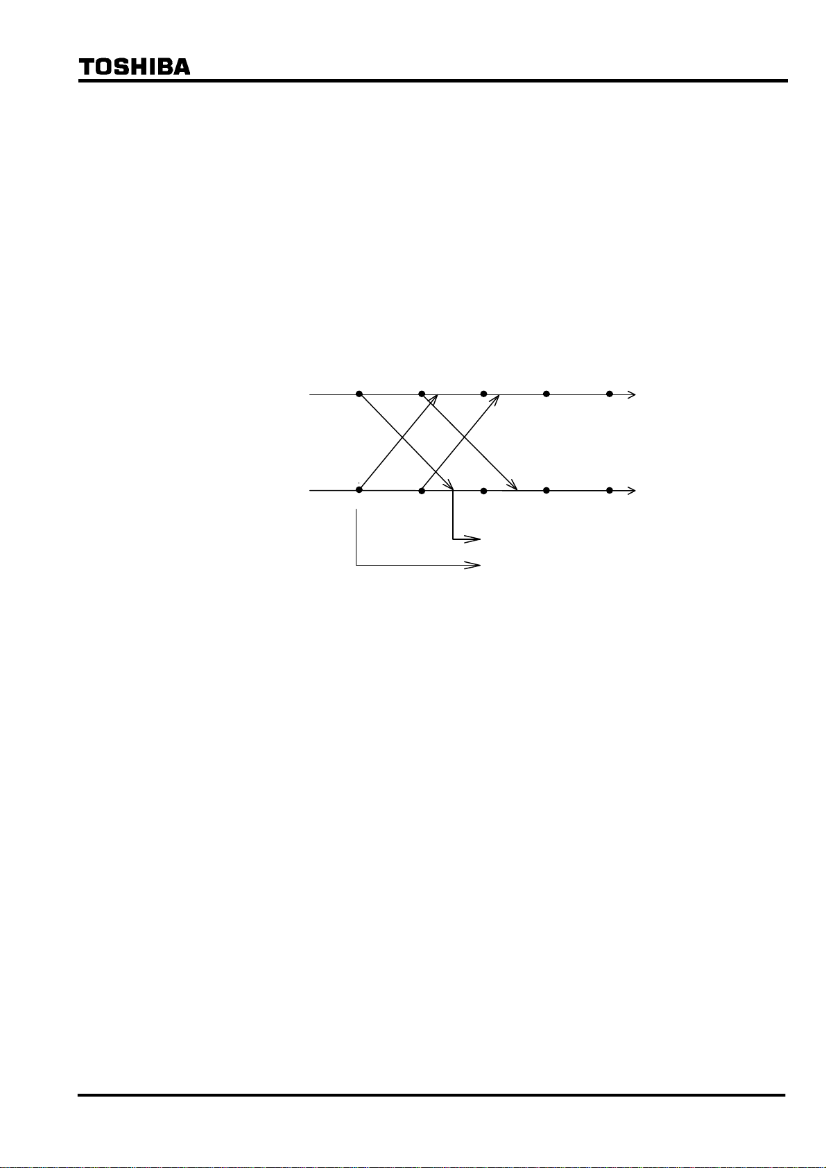
2.2.7.3 Differential Current Calculation
Synchronized sampling allows correct calculation of differential current even in the presence of
a transmission time delay. This processing is indicated in Figure 2.2.7.6. As indicated in the
figure, sampling synchronization is established between terminals A and B, and both the
sampling timing and sampling address match. The instantaneous current data and sampling
address are both sent to the other terminal. The GRL100 refers to the sampling address affixed to
the received data and uses local data with the same sampling address to calculate the differential
current. This allows both terminals to use data sampled at the same instant to perform the
differential current calculation, no matter how large the transmission time delay is.
Terminal A
4 3210
t
i
A(0)
i
B(0)
Terminal B
Figure 2.2.7.6 Calculation of Differential Current with Transmission Delay Time
i
B(1)
i
A(1)
i
A(0)
Differential current calculation
i
B(0)
Sampling address number
t
4 3210
Protection in anomalous power system operation
Even when any of the terminals is out-of-service, the GRL100 in-service terminal can still
provide the differential protection using the out-of-service detection logic. For details of the
out-of-service detection logic, see Section 2.2.2.
When one terminal is out-of-service in a two-terminal line, the other terminal continues the
current differential protection using the local current irrespective of whether it is a master
terminal or a slave terminal.
When one terminal is out-of-service in a three-terminal line, synchronized sampling is
established between the remaining two terminals as follows and the differential protection is
maintained.
• If the master terminal is out-of-service, one of the slave terminals takes over the master
terminal synchronized sampling function and enables current differential protection
between the remaining terminals to be performed.
• If the slave terminal is out-of-service, the master and another slave terminal maintain the
differential protection.
When two terminals are out-of-service in a three-terminal line, the remaining terminal continues
the current differential protection using the local current irrespective of whether it is a master
terminal or a slave terminal.
2.2.8 Charging Current Compensation
When differential protection is applied to underground cables or long overhead transmission
⎯ 25 ⎯
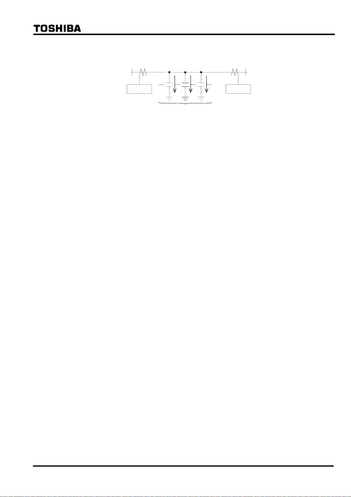
6 F 2 S 0 8 3 5
lines, the charging current which flows as a result of the capacitance of the line (see Figure
2.2.8.1) appears to the protection relay as an erroneous differential current.
Terminal A Terminal B
GRL100 GRL100
Ic
Figure 2.2.8.1 Charging Current
The charging current can be compensated for in the setting of the relay’s differential protection
sensitivity but only at the expense of reduced sensitivity to internal faults. In addition, the actual
charging current varies with the running voltage of the line and this must be taken into account in
the setting.
In order to suppress the effect of the charging current while maintaining the sensitivity of the
differential protection, GRL100 is equipped with a charging current compensation function,
which continuously re-calculates the charging current according to the running line voltage and
compensates for it in its differential current calculation. The running line voltage is measured by
VT inputs to GRL100.
The user enters values for line charging current and for the line voltage at which that charging
current was determined in the settings [DIFIC] and [Vn], and these values are used by the relay
to calculate the capacitance of the line. The relays at each line end share the line capacitance
between them, that is they divide by two for a two-terminal line, and by three for a three-terminal
line. In the case of a three-terminal line, if the relay at one terminal is out-of-service for testing
(see out-of-service terminal detection), the other two terminals are automatically re-configured
to divide the line capacitance by two.
Each terminal continuously calculates its share of the charging current at the running line voltage
on a sample by sample basis as follows:
Ic = C
dV
/ dt
where,
Ic = line charging current
C = line capacitance calculated from settings [DIFIC] and [Vn]
V = measured line voltage
The relay then calculates the line current compensated for the charging current on a sample by
sample basis as follows:
I = I’ - Ic
where,
I = compensated current
I’ = actual measured current
Note that since GRL100 calculates both the charging current and compensated line current on a
sample by sample basis, all necessary phase information is inherently taken into account.
⎯ 26 ⎯

6 F 2 S 0 8 3 5
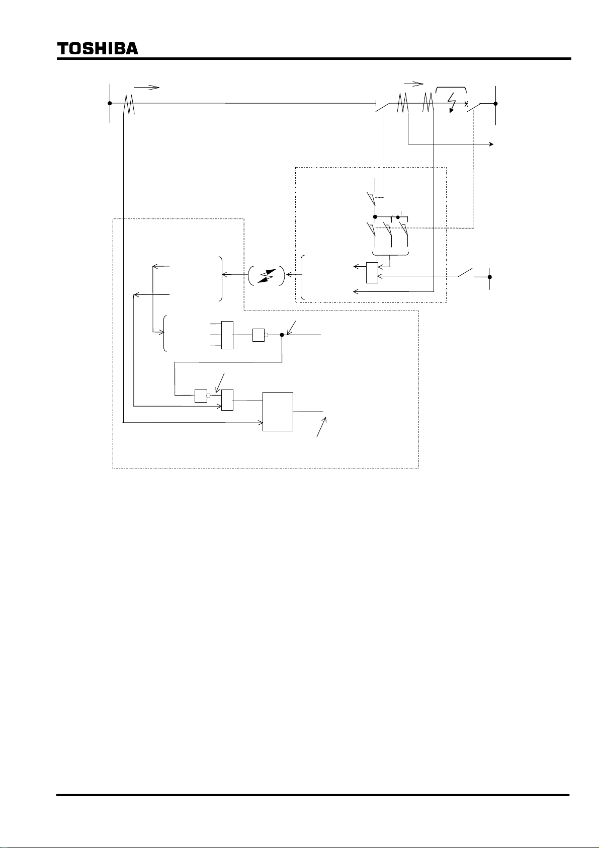
2.2.9 Blind Zone Protection
The GRL100 relay has “Out-of-Service Detection Logic” as described in Section 2.2.2. This
logic functions automatically to detect the remote CB or DS (line disconnecting switch) opened
condition as shown in Figure 2.2.9.1. If the remote CB or DS is opened, the received remote
current data is set to “zero” Ampere at the local terminal, and the local relay can be operated with
only local current like a simple over current relay. Therefore, this logic function is used for blind
zone protection.
The zone between CB and CT at the remote terminal is the blind zone in Figure 2.2.9.1. If a fault
occurs within this zone, the busbar protection should operate first and trip the CB at the remote
terminal, but the fault remains and the fault current (IF) is fed continuously from the local
terminal. Since this phenomenon is an external fault for the current differential protection
scheme, the blind zone fault cannot be cleared. The fault may be cleared by remote backup
protection following a time delay, but there is a danger of damage being caused to power system
plant. Fast tripping for this type of fault is highly desirable. The Out-of-Service Detection Logic
is effective for a fault where a blind zone between CT and CB on the line exists as shown in
Figure 2.2.9.1.
If the CB and DS condition are introduced at the remote terminal as shown in Figure 2.2.9.1, the
GRL100 relay at the local terminal can operate with only local current and the fault can be
cleared, because the remote current data is automatically cancelled as explained above.
Please note the “CB Close Command” signal must be connected to the GRL100 relay to prevent
unwanted operation for a CB close operation (manual close and/or autoreclose). Unwanted
operation may be caused if the close timing of the CB auxiliary contact is delayed relative to the
CB main contact. Therefore, the CB close command signal resets forcibly the Out-of-Service
Detection Logic before the CB main contact is closed.
CB and DS status signals are input by PLC. If the out-of-service detection is not used, its logic
can be blocked by the scheme switch [OTD].
⎯ 27 ⎯
6 F 2 S 0 8 3 5
LOCAL
IL (=IF)
DIFF RELAY GRL100
(LOCAL)
CBDS-A,B,C
IR(Current)
CBDS-A
CBDS-B
CBDS-C
≧1
LINE
DIFF RELAY GRL100
(REMOTE)
52A 52C 52B
Comm. Link
1
(Cancel circuit of rem ot e t e rminal current IR)
CBDS-A,B,C
IR(Current)
(Remote terminal closed: “0” logic)
Remote terminal “OPEN”
≧
IR (=IF)
DS
89L1
1
Blind Zone
CB
FAULT
CB CLOSE COMMAND
REMOTE
BUSBAR
PROT.
1
&
IR
IL
If DS or CB signals (CBDS -A, B, C) changes to “ 0” , r emo te cu rrent d ata
(IR) is cancelled to zer o (0). Therefor e, differential curr ent (Id ) eq uals to
local current (IL).
Σ
Differential Current (Id)
Figure 2.2.9.1 Blind Zone Protection
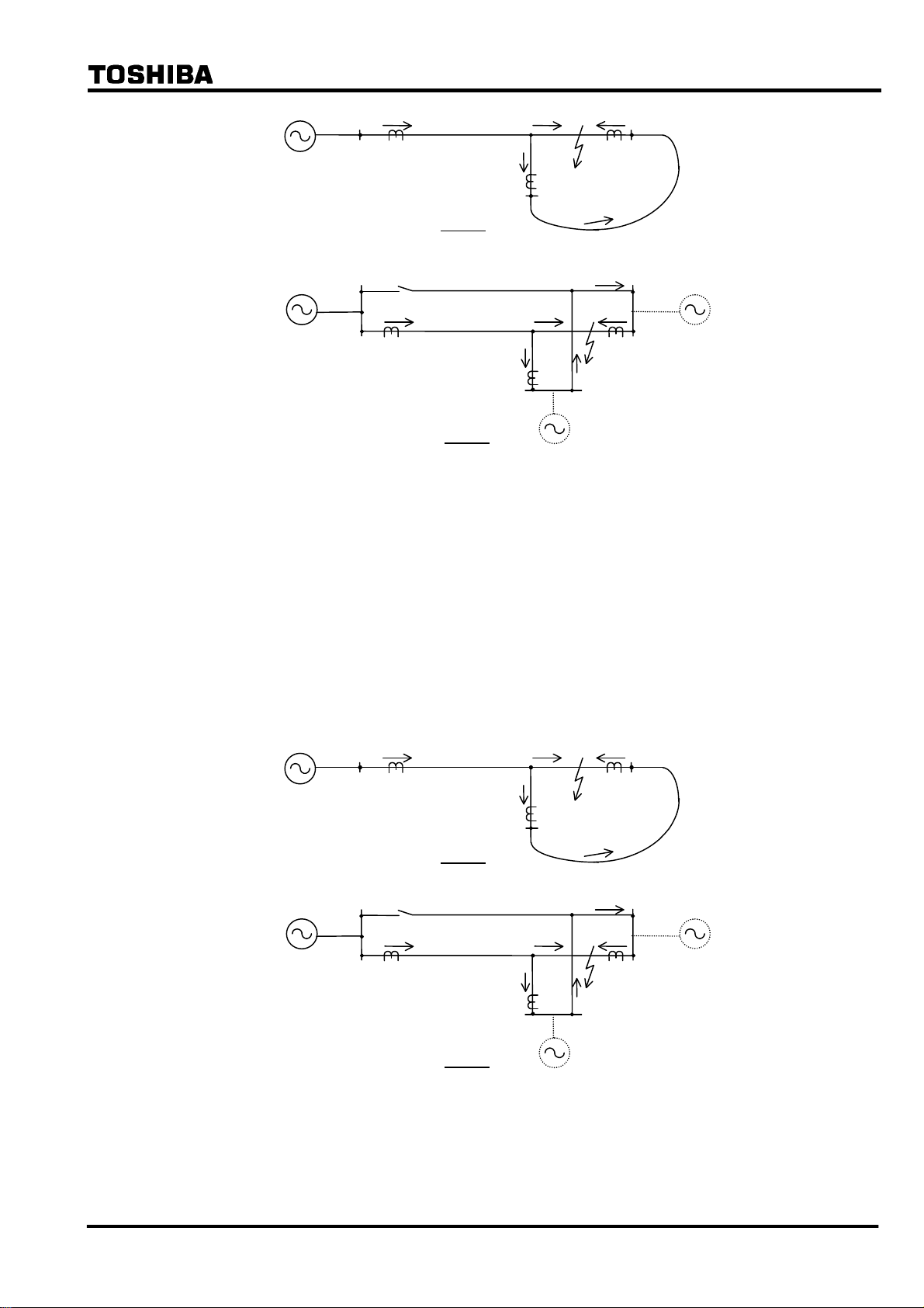
2.2.10 Application to Three-terminal Lines
When current differential protection is applied to a three-terminal line, special attention must be
paid to the fault current flowing out of the line in the case of an internal fault and CT saturation at
the outflowing terminal in case of an external fault.
Fault current outflow in case of internal fault
In case of a two-terminal line, fault current never flows out from the terminals for an internal
fault. But in case of a three-terminal line with an outer loop circuit, a partial fault current can
flow out of one terminal and flow into another terminal depending on the fault location and
magnitude of the power source behind each terminal.
Case 1 in Figure 2.2.10.1 shows a fault current outflow in a single circuit three-terminal line with
outer loop circuit. J and F in the figure indicate the junction point and fault point. A part of the
fault current flowing in from terminal A flows out once from terminal C and flows in again from
terminal B through the outer loop.
Case 2 shows the outflow in a double-circuit three-terminal line. The outer loop is generated
when one terminal is open in the parallel line. A part of the fault current flowing in from terminal
A flows out from the fault line to the parallel line at terminal C and flows in again at terminal B
through the parallel line.
⎯ 28 ⎯
A
A
A
A
6 F 2 S 0 8 3 5
J
C
Case 1
B F
Open
Case 2
C
J
F
B
Figure 2.2.10.1 Fault Current Outflow in Internal Fault
The larger current outflows from terminal C when the fault location is closer to terminal B and
the power source behind terminal C is weaker. In case of a double-circuit three-terminal line,
50% of the fault current flowing in from terminal A can flow out from terminal C if terminal C is
very close to the junction and has no power source behind it.
These outflows must be considered when setting the differential element.
CT saturation for an external fault condition
In case of a two-terminal line, the magnitude of infeeding and outflowing currents to the external
fault is almost the same. If the CTs have the same characteristics at the two terminals, the CT
errors are offset in the differential current calculation.
B
J
C
Case 1
Open
J
C
Case 2
F
B
F
Figure 2.2.10.2 Fault Current Distribution
But in case of a three-terminal line, the magnitude of the current varies between the terminals
and the terminal closest to the external fault has the largest magnitude of outflowing fault
current. Thus, the CT errors are not offset in the differential current calculation. Thus, it is
⎯ 29 ⎯
 Loading...