

Toshiba GRE110 Instruction Manual

6 F 2 T 0 1 7 2
( Ver. 5.3)
INSTRUCTION MANUAL
OVERCURRENT PROTECTION RELAY
GRE110
© TOSHIBA Corporation 2013
All Ri ghts Reserved.
DANGER
WARNING
Safety Precautions
Before u sing this produc t, p lease read this c hapter carefully.
This chapter describes the safety precautions recommended when using the GRE110. Before
installing a nd using the equi pment, thi s chap ter mus t be thoroughly r ead and u nderstood.
Explanation of symbols used
Signal words such as DANGER, WARNING, and t wo kinds of C AUTION , will b e followed by
important safety information that mus t be ca refully reviewed.
Indicates an imminently hazardous situation which will result in death or serious
injur y i f you do not follow the instruct i ons.
Indicates a potentially hazardous situation which could result in death or serious
injur y i f you do not follow the instruct i ons.
CAUTION Indica tes a pot entia lly ha za rdou s s itu at ion which if not a voided, ma y resu lt i n
minor injury or moder ate inju ry.
6 F 2 T 0 1 7 2
CAUTION Indica tes a pot entia lly ha za rdou s s itu at ion which if not a voided, ma y resu lt i n
property damage.
1

DANGER
WARNING
• Current transformer circuit
Never allow the current transformer (CT) secondary circuit connected to this equipment to be
opened while the pr imar y sys tem is li ve. Op ening the C T c irc uit will pr oduce a da ngerou sly high
voltage.
• Exposed terminals
Do not touch the terminals of this equipment while the power is on, as the high voltage generated is
dangerous.
• Residual voltage
Haz ar dous volta ge can be pres ent in the cir cuit jus t a ft er s witchi ng off t he power s up ply. It t a kes
approx imately 30 seconds for the voltage to dischar ge.
6 F 2 T 0 1 7 2
CAUTION
• Earth
The earthing terminal of the equipment must be sec urely earthed.
CAUTION
• Operating environment
The equipment must only used within the range of ambient temperature, humidity and dust detailed
in the sp ec if i c ation and in an environment free of abnor mal vibr ation.
• Ratings
Before a pplying AC vol tage a nd cur rent or t he power sup ply to the equip ment, check t hat they
confor m t o the equipment rati ngs.
• Printed circuit board
Do not attach and remove printed circuit boards when the DC power to the equipment is on, as this
may ca use the equipment to malf unction.
• External circuit
When connecting t he outp ut cont act s of t he equipment to a n exter nal cir cuit , c ar efully c heck the
sup ply voltage used in or der to prevent the connec ted circuit from overheating.
• Connection cable
Ca refully handle the connect ion cable without app lyi ng ex c essive for c e.
• Power supply
If power supply has not been supplied to the relay for two days or more, then all fault records, event
recor ds a nd dis tu r b a nce r ecor ds and int er na l cloc k may be clear ed soon a ft er r est oring t he power .
This is because the bac k -u p RAM ma y have discharged a nd may contain uncer tain data .
• Modification
Do not modify this equip ment, as this ma y c aus e the equipment to malfunction.
• Disposal
When disposing of this equipment, do so in a safe manner acc ording to loc al regulations.
2

Contents
Safety Precautions 1
1. Introduction 6
2. Application Notes 8
2.1 Phase Overcurrent and Residual Overcurrent Protection 8
2.2 Instantaneous and Staged Definite Time Overcurrent Protection 16
2.3 Sensitive Earth Fault Protection 23
2.4 Phase Undercurrent Protection 34
2.5 Thermal Overload Protection 36
2.6 Negative Sequence Overcurrent Protection 38
2.7 Broken Conductor Protection 40
2.8 Breaker Failure Protection 43
6 F 2 T 0 1 7 2
2.9 Countermeasures for Magnetising Inrush 46
2.10 Trip Signal Output 49
2.11 Application of Protection Inhibits 51
2.12 CT Requirements 53
2.13 Autoreclose 55
3. Technical Description 62
3.1 Hardware Description 62
3.2 Input and Output Signals 64
3.3 Automatic Supervision 69
3.4 Recording Function 75
3.5 Metering Function 78
3.6 Control Function 78
4. User Interface 79
4.1 Outline of User Interface 79
4.2 Operation of the User Interface 82
4.3 Personal Computer Interface 150
4.4 MODBUS Interface 150
4.5 IEC 60870-5-103 Interface 150
4.6 IEC 61850 Communication 150
4.7 Clock Function 151
4.8 Special Mode 152
5. Installation 153
5.1 Receipt of Relays 153
5.2 Relay Mounting 153
3

6 F 2 T 0 1 7 2
5.3 Electrostatic Discharge 157
5.4 Handling Precautions 157
5.5 External Connections 157
5.6 Optinal case model S1-GRE110, S3-GRE110 157
6. Commissioning and Maintenance 158
6.1 Outline of Commissioning Tests 158
6.2 Cautions 158
6.3 Preparations 159
6.4 Hardware Tests 160
6.5 Function Test 162
6.6 Conjunctive Tests 172
6.7 Maintenance 174
7. Putting Relay into Service 177
Appendix A 178
Programmable Reset Characteristics and Implementation of Thermal
Model to IEC60255-149 178
Appendix B 184
Signal List 184
Appendix C 192
Event Record Items 192
Appendix D 197
Binary Output Default Setting List 197
Appendix E 200
Relay Menu Tree 200
Appendix F 211
Case Outline 211
Appendix G 214
Typical External Connection 214
Appendix H 224
Relay Setting Sheet 224
Appendix I 242
Commissioning Test Sheet (sample) 242
Appendix J 246
Return Repair Form 246
Appendix K 251
Technical Data 251
4

6 F 2 T 0 1 7 2
Appendix L 257
Symbols Used in Scheme Logic 257
Appendix M 260
Modbus: Interoperability 260
Appendix N 290
IEC60870-5-103: Interoperability 290
Appendix O 297
PLC Default setting 297
Appendix P 299
Inverse Time Characteristics 299
Appendix Q 305
IEC61850: Interoperability 305
Appendix R 347
Ordering 347
The da ta given in t hi s manual are subj ect to change without notice. ( Ver.5.3)
5

1. Introduction
GRE110 series relays provide non-directional overcurrent protection for radial distribution
Medium Voltage class networks, and back-up p rotection for di str ibution networks.
Note: GRE110 series relays are non-directional, and are applicable to systems where fault current
flows in a fixed direction, or flows in both directions but there is a significant difference in
magnitude. In systems where a fault c urrent flow s in b oth directio ns and there is not a significant
diff erence in the magnitude of the fault current, the directional overcurrent prot ectio n provided
by GRE140 facilitates fault selectivity.
The GRE110 series provides the following p rotection schemes in a l l models.
• Overcurrent protection for phase and earth faults with definite time or inverse time
characteristics
• Ins tant aneous overcurrent prot ection for phase and ear th faults
6 F 2 T 0 1 7 2
The GRE110 seri es provides the sensitive ear th faul t protection scheme depending on the models.
The GRE1 10 series provides the fol lowing f unctions for all models.
• Two settings groups
• Configur able binary inputs and outputs
• Circuit breaker control and condition monit oring
• T rip cir c u it supervision
• Autoreclos i ng f unction
• Automa tic self-supervision
• Menu-based HMI system
• Configur able LE D indication
• Met ering and recording functi ons
• F ront mount ed USB port for loca l PC communications
• Rear mounted RS485 serial ports for communications
Table 1.1.1 shows the members of the GRE110 series and identifies the functions to be provided by
eac h memb er.
6

Model 400 provides three phase and earth fault overcurrent protection.
6 F 2 T 0 1 7 2
Table 1.1.1 Series Members and Functions
Model Number GRE110 -
400 401 402 420 421 422 820 821
Current input 3P + E 3P + E
(*)
+ SE 2P + Vo + SE
Binary Input port 2 6 6 2 6 6 2 6
Binary Output port 4 4 8 4 4 8 4 4
IDMT O/C (OC1, OC2)
DT O/C (OC1 – 4)
Instantaneous O/C (OC1 – 4)
IDMT Earth Fault O / C (EF1, E F2)
DT Earth Faiult O / C (EF1 – 4)
SEF protection (SEF1 – 4)
Phase U/C
Thermal O/L
NPS O/C
Broken conductor protection
CBF protection
Inrush current detector
Cold load protection
Auto-reclose
Trip circuit supervision
Self supervision
CB state monitoring
Trip counter alarm
∑Iy alarm
CB operate time alarm
Fault records
Event records
Disturbance records
Modbus Communication
IEC60850-5-103 Communication
IEC 61850 communicat i on (option) () ()
Case width (mm) 149 149 223 149 149 223 149 149
E: current from residual circuit or CT SE: cu rrent from core bala nce CT 3P: three-phase current
(*)
E
: current (Io) calculated from three-phase current in relay internal DT: definite time
IDMT: inverse definite minimum time O/C: overcurrent protection U/C: undercurrent protection
OC∗: phase overcu rrent elem ent O/L: overload protection NPS: nega t ive phas e s eq u ence
EF∗: earth fault element SEF: sensitive earth fault CBF: circuit breaker failure
Model 420 provides three phase, earth fault and sensitive earth fault protection.
7
TC
TC
A
B
C
Operate time
2. Application Notes
2.1 Phase Overcurrent and Residual Overcurrent Protection
GRE110 provides protection for radial distribution networks with phase fault and earth fault
over curr ent element s OC1 to OC4 and EF1 to EF4 *. T he protection of local and downstr eam
terminals is coordinated with the current setting, time setting, or both.
*at model 400, 401 and 402, the ear th fa u lt cur r ent inp ut ma y be c onnected ei t her i n t he resi du a l
circ uit of the p has e CT s, or alt erna ti vely a dedica ted ea rt h fa ult CT may be used. In the ca se of
connection in the residual circuit of the phase CTs, the settings of the phase CT ratio OCCT and the
earth fault CT ratio EFCT should be equal. On the other hand, where a dedicated earth fault CT is
applied, then the settings of OCCT and EFCT should NOT be equal, and in this case the measuring
range of ear th fault cu rrent i s limited to 2 0A maximum (s ee s ection 2. 2.5) .
** On GRE110-820 and 821 models, cu r r ent inpu t s a r e A pha s e a nd C phase only. The B pha s e
element is currucur ate fr om A phase and C phase cur rent for metering function. But B phase
cullcurated current is not for protection and recording function. So the B phase cur rent is not
operate at the some sc heme logic.
6 F 2 T 0 1 7 2
2.1.1 Inverse T i me Overcurrent Protection
In a system for which the fault current is practically determined by the fault location, without being
substantially affected by changes in the power source impedance, it is advanta geou s to use inverse
definite minimum time (ID MT) overcur rent prot ection. This prot ection p rovides reas onably fast
tripping, even at a terminal close t o the power s ource where th e most sever e faults ca n o ccur.
Where ZS (the impedance between the relay and the power s ource) is small compared with that of
the protected section ZL, there is an appreciable difference between the current for a fault at the far
end of the section (ES /(ZS +ZL ), ES : sourc e voltage), and the cu rr ent for a fa ult a t t he near end
(ES/ZS). When operating time is inversely proportional to the current, the relay operates faster for
a fault at t he end of the section nearer the power s ource, and the op erating time ratio for a fault at
the near end to the far end is ZS/(ZS + ZL).
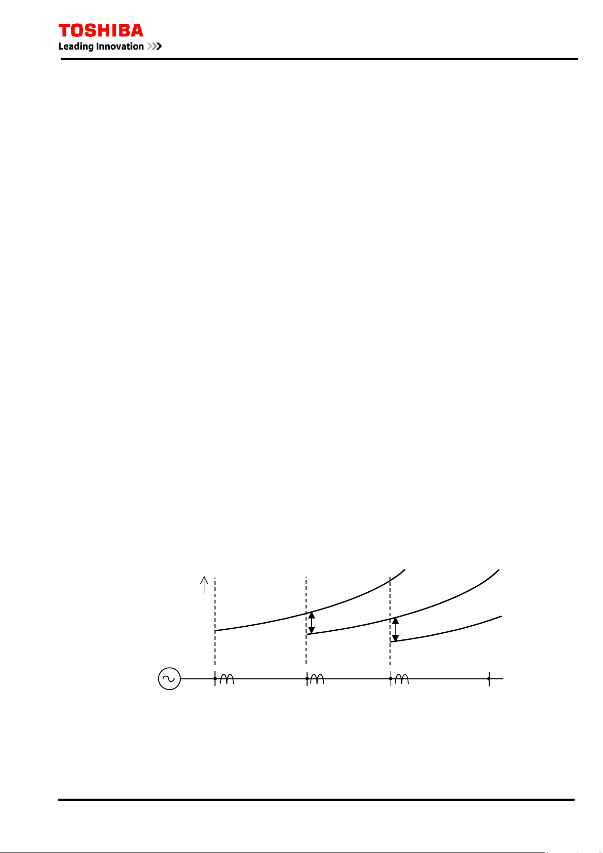
The r esultant time-distance characteristics are shown in Figure 2.1. 1 for radial networks with
sever al f eeder s ec t io ns . With t he sa me selective ti me coordina tion ma rgin T C as the downstream
section, the operat i ng time can be furt her reduc ed by using a more inverse characteristic.
Figure 2.1.1 Time-distance Characteristics of In verse Time Prot ect ion
The OC 1 and EF 1 element s for s tage-1 have IDMT characteristics defined by equation (1) in
accordanc e with IEC 6025 5-151:
8

( )
+
−
×=
c
Is
I
k
TMS
t
1
α
0.1
1
10
100
1000
1 10 100
Operating Time (s)
Curr ent (M ultipl e of S etting )
IEC/UK Inverse Curves
(T ime Mu lt iplie r = 1 )
LTI
NI
VI
EI
0.1
1
10
100
1 10 100
Operating Time (s)
Current (Multiple of Setting)
IEEE/US Inverse Cu rv es
(Time Multiplier = 1)
MI
VI
CO2
CO8
EI
(1)
6 F 2 T 0 1 7 2
where:
t = o perating time for c onsta nt current I (seconds ) ,
I = en ergising c urrent (a mps),
Is = overcurrent setting ( amps),
TMS = time multiplier s et ting,
k, α, c = c onsta nts defining c urve.
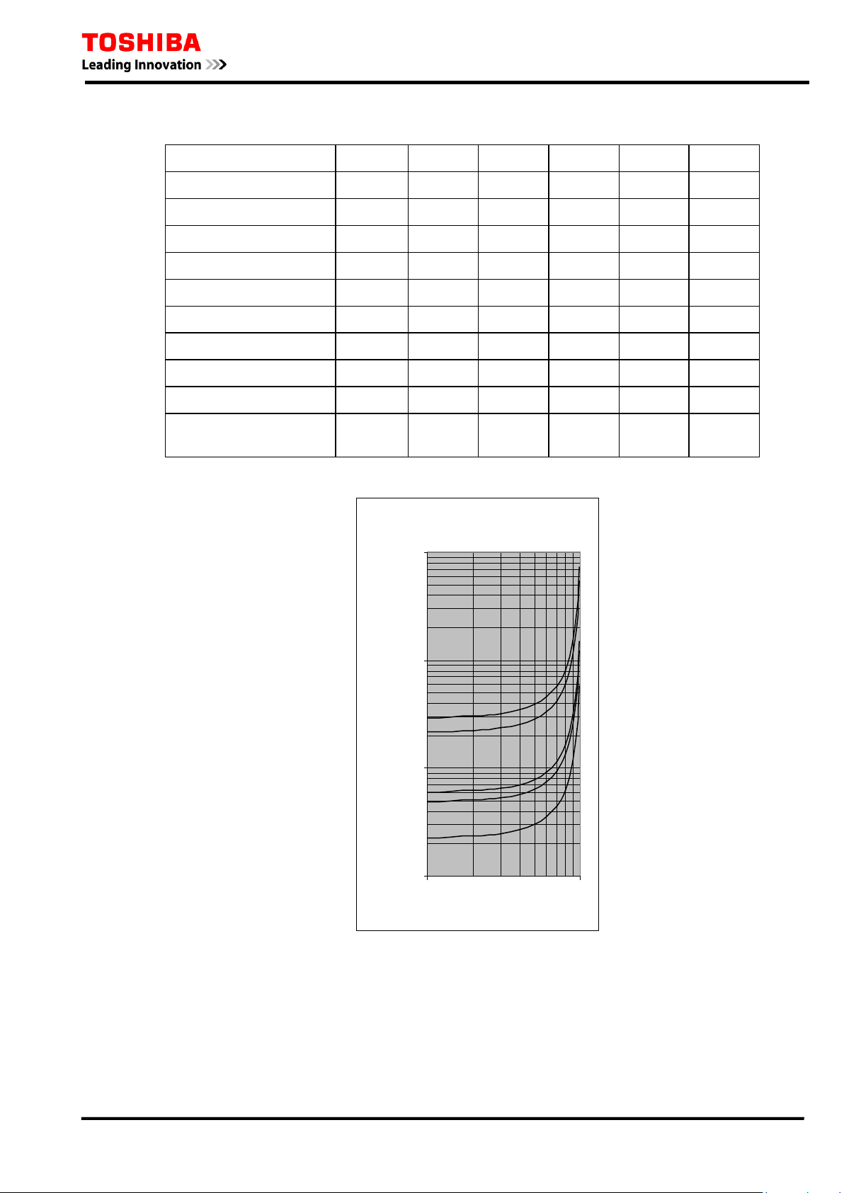
Nine cu rve types are ava ilable as defined in Table 2.1.1. Th ey ar e illustr ated in Figure 2.1.2.
In addit ion to the ab ove nine cur ve types, OC 1 and EF 1 can pr ovide user configurable IDMT
curves. If required, set the scheme switch [M∗∗∗] to “C” and set the curve defining consta nts k, α
and c. The following table shows the setti ng ranges of the cur ve defini ng c onsta nts. OC2 and EF 2
for sta ge-2 also p rovide the same inverse t ime protect i on as OC1 a nd E F1.
Figure 2.1.2 IDMT Characteristics
Programmable Reset Characteristics
OC1 and EF1 have a programmable reset feature: instantaneous, definite time delayed, or
dependen t ti me delayed reset. (R efer to Appendix A for a more detailed descr iption. )
Instantaneous resetting is normally applied in multi-shot auto-reclosing schemes, to ensure corr ect
9

−
×=
β
S
I
I
kr
RTMSt
1
6 F 2 T 0 1 7 2
gra di ng between rela ys at various points in the s c heme.
The inverse reset c hara cteris tic is par ticula rly us eful for providing cor rect coordinat ion with an
ups trea m indu c tion disc type overc urr ent rela y.
The definite time delayed reset characteristic may be used to provide faster clearance of intermittent
(‘pecki ng’ or ‘flashing’) fault conditions.
Definite time reset
The definite time reset ting charac teris tic is applied to the IEC/IE EE/US operating character i stics .
If defin ite tim e resetting is selected, and the delay period is set to instantaneous, then no intentional
delay is added. As soon as the energising current falls below the reset threshold, the element returns
to its reset condition.
If the delay per iod is set t o some va lue in seconds , then a n intenti onal dela y is a dded to t he res et
period. If the energising current exceeds the setting for a transient period without causing tripping,
then res etti ng is dela yed for a u ser -definable p eriod. When the ener gising cu r rent fa lls b elow th e
reset threshold, the integra l sta te (the point towa rds op erat ion tha t it ha s t ravelled) of the timing
function (IDMT) i s held for that period.
This does not apply following a trip operat ion, in which case resetting is alwa ys inst anta neous.
Dependent time reset
The dependent time resetting characteristic is applied only to the IEEE/US operate characteristics,
and is defi ned b y the following equa tion:
(2)
where:
t = time r eq uir ed for the element to reset fu l ly after compl ete operation (seconds),
I = en ergising c urrent (a mps),
Is = overcurrent setting ( amps),
k
= time req uir ed t o res et full y a ft er comp let e oper a t ion wh en th e ener gising cu rr ent i s zer o
r
(see Table 2.1.1),
RTMS = reset time multiplier setting.
k, β, c = cons tant s defining curve.
Fig ure 2.1.3 illust ra tes the depen d en t ti me reset characteristi cs.
The dependent time reset characteristic also can provide user configurable IDMT curve. If
required, set the scheme switch [M∗∗∗] to “C” and set the curve defining constants kr and β. Table
2.1.1 shows the s etting r anges of t he c urve defining consta nts.
10
I EEE R eset C urves
(Time Multiplier = 1)
1.00
10.00
100.00
1000.00
0.1 1
Current (Multiple of Setting)
Time (s)
MI
VI
EI
CO2
6 F 2 T 0 1 7 2
Table 2.1.1 Specification of IDMT Curves
Curve Description IEC ref. k
α
c k
r
IEC Normal Inverse A 0.14 0.02 0 - IEC Very Inverse B 13.5 1 0 - IEC Extremel y Inverse C 80 2 0 - UK Long Time Inverse - 120 1 0 - IEEE Moderately I nverse D 0.0515 0.02 0.114 4.85 2
IEEE Very Inverse E 19.61 2 0.491 21.6 2
IEEE Extremel y Inverse F 28.2 2 0.1217 29.1 2
US CO8 Inverse - 5.95 2 0.18 5.95 2
US CO2 Short Tim e I nverse - 0.02394 0.02 0.01694 2.261 2
User configurable curve - 0.00 –
300.00
0.00 –
5.00
0.000 –
5.000
0.00 –
300.00
Note: kr and β are used to define the r es et characterist ic. Refer t o equation (2).
β
0.00 –
5.00
2.1.2 Definite T i me Overcurrent Protection
Figure 2.1.3 Dependent Time Reset Characteristics
In a syst em in which the fault c ur rent does not var y a gr ea t dea l in rela t ion to t he posit ion of t he
fault, that is, the impedance between the relay and the power source is large, the a dvantages of the
11
Operate time
TC
TC
A
B
C
6 F 2 T 0 1 7 2
IDMT char acteris tics ar e not fully utilised. In t his case, definite time overcu rrent pr otection i s
applied. The operating ti me can be constant irrespect ive of the magnitu de of the fau lt current.
The definite time overcurrent protection consists of instantaneous overcu rrent measuring elements
OC1 and EF1 and delayed pick-up time rs started by th e elements, and provides selective protection
with gra ded sett ing of the dela yed pick-up timers. Thu s, t he consta nt t ime coordinat ion with t he
downstream section can be maintained as shown in Figure 2.1.4 As is clear in the figure, the nearer
to the power sou rce a sect ion is, the gr eater the delay i n the tr ipping t ime of the sect ion. T his is
undesirabl e p articularly wher e there are many sections in t he series.
2.1.3 Scheme Logic
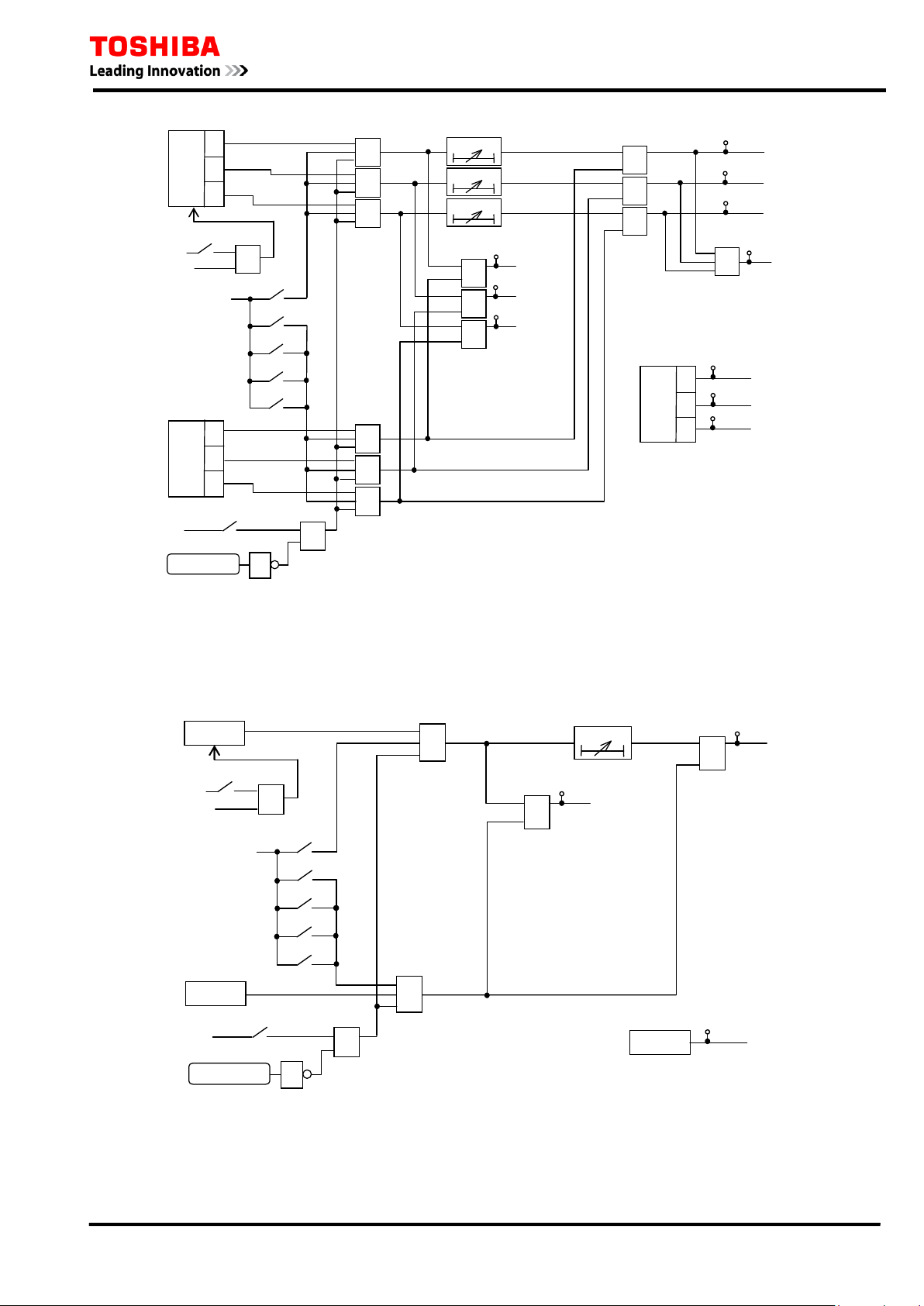
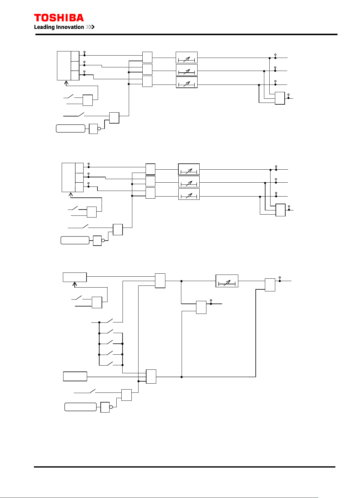
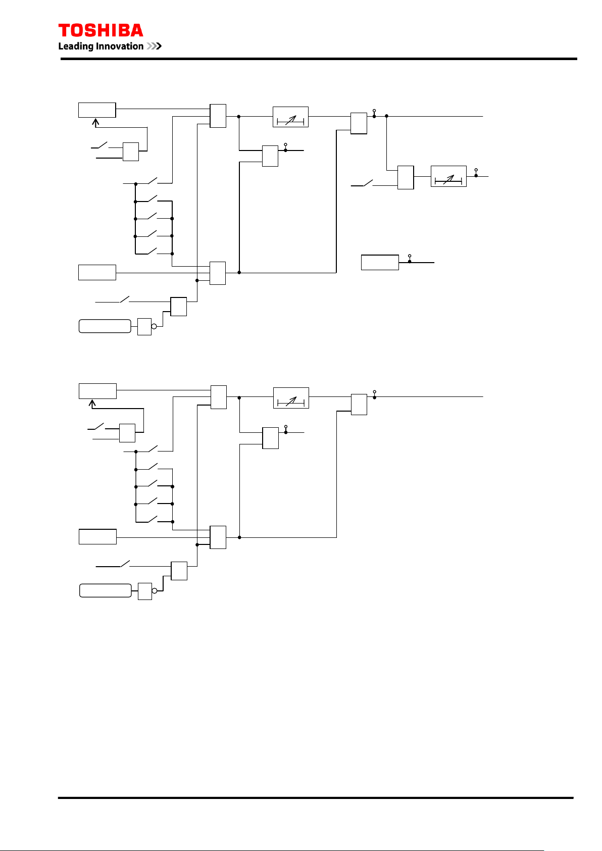
Figure 2.1.5 and Figure 2.1.6 show the scheme logic of the phase fault and earth fault overcurrent
protection with selective definite time or inverse time char acteristic.
The definite time pr otection is selected by setting [MOC1] and [MEF1] to “D”. Definite t ime
over cur rent el ements OC1 -D and EF 1-D are enab led for pha se fault and eart h fault p rotection
respectively, and trip signal OC1 TRIP and EF1 TRIP are given through the delayed pick-up timer
TOC1 a nd TEF1.
The inverse time protection is selected by setting [MOC1] and [MEF1] to either “IEC”, “IEEE” or
“US” ac cordi ng to t he IDMT cha r ac ter ist ic t o employ. Inver se t ime overcur r ent elements O C1 -I
and EF1-I are enabled for p hase fault and earth f ault protection respectively, and trip signal OC1
TR IP a nd EF1 TRIP are given.
ICD is the inrush current detector ICD, which detects second harmonic inrush current during
transformer energisa tion etc. , and c an block t he OC 1 -D el ement b y t h e s cheme s wi t c h [ OC1-2F]
respectively . See Section 2 .9.
The signals OC1 HS and EF 1 HS are used for blocked over c urrent protection and blocked b usbar
protection (refer to Sect ion 2.1 2).
These protections can be disabled by the scheme switc hes [OC1 EN] a nd [ EF1EN] or binary input
signals OC1 BLOCK and EF1 BLOCK.
Figure 2.1.4 Defini t e Time Overcurrent Protection
OC2 and EF 2 are provided wit h the same logic of OC1 and EF 1.
12
≥1
OC1 TRIP
OC1 BLOCK
1
0.00 - 300.00s
&
TOC1
t
0
"IEC
"
"IEEE"
+
"ON"
[OC1EN
+
C
B
A
OC1
-D
&
t
0
≥1
&
t
0
≥1
&
C
B
A
&
&
"US"
"C"
≥1
≥1
≥1
&
≥1
102
OC1-A
TRIP
103
104
101
OC1-B TRIP
OC1-C TRIP
51
OC1-A
52
53
OC1-B
OC1-C
"D"
OC1
-I
&
[MOC
1]
+
[OC1-2F]
ICD
“Block”
C
B
A
OC1
HS
OC1-A HS
88
OC1-B HS
89
OC1-C HS
90
EF1-D
≥1
EF1 TRIP
&
0.00 - 300.00s
TEF1
t
0
EF1-I
EF1 BLOCK
1
"ON"
[EF1EN]
+
&
"D"
[MEF1]
"
IEC"
"IEEE"
+
"
US"
"C"
&
≥1
117
63
EF1
&
ICD
“Block”
+
[EF1-2F]
EF1HS
EF1 HS
91
6 F 2 T 0 1 7 2
Figure 2.1.5 Phase Fau lt Overcurrent Protection OC1
Figure 2.1.6 Earth Fault Overcu rrent Protectio n EF1
13

6 F 2 T 0 1 7 2
2.1.4 Settings
The ta b le shows t he sett ing elements neces sa ry f or t he pha se a nd res idua l overc ur rent pr ot ection
and t heir setting ranges.
Element Range Step Default Remarks
OCCT 1 - 20000 1 400 CT ratio for 3-phase current
EFCT 1 - 20000 1 200 CT ratio f or earth-fault curret
OC1 0.10 – 25.00 A 0.01 A 1.00 A OC1 threshold setting
TOC1 0.010 – 1.500 0.001 1.000 OC1 time multiplier setting. Requi red i f [MOC1] =
IEC, IEEE, US or C.
0.00 – 300.00 s 0.01 s 1.00 s OC1 definite t ime setting. Required if [MOC1] =
DT.
TOC1R 0.0 – 300.0 s 0.1 s 0.0 s OC1 defi ni t e time delayed reset. Requi red if
[MOC1] = IEC or if [OC1R] = DEF.
TOC1RM 0.010 – 1.500 0.001 1.000 OC1 dependent time delayed reset time multiplier.
Required if [OC 1R ] = D EP .
EF1 0.05 – 25.00 A 0.01 A 0.30 A EF1 threshold setting
TEF1 0.010 – 1.500 0.001 1.000 EF1 ti m e m ul tiplier setting. Required if [MEF1] =
IEC, IEEE, US or C.
0.00 – 300.00 s 0.01 s 1.00 s EF1 definite time setting. Required if [MEF1] =DT.
TEF1R 0.0 – 300. 0 s 0.1 s 0.0 s EF1 defini t e time delayed reset. R equi red i f
[MEF1] = IEC or if [EF1R] = DEF.
TEF1RM 0.010 – 1.500 0.001 1.000 EF1 dependent time delayed reset time multiplier.
Required if [EF1R ] = D EP .
[OC1EN] Off / On On OC1 Enable
[MOC1] D / IEC / IEEE / US / C D OC1 characteristic
[MOC1C]
MOC1C-IEC
MOC1C-IEEE
MOC1C-US
[OC1R] DEF / DEP DEF OC1 reset characteristic. R equi red i f [ MOC1] =
[OC1-2F] NA / Block NA OC1 2f block Enable
[EF1EN] Off / On On EF1 Enabl e
[MEF1] D / IEC / IEEE / US / C D EF1 characterist i c
NI / VI / EI / LTI
MI / VI / EI
CO2 / CO8
NI
MI
CO2
OC1 inverse curve type.
Required if [MO C 1] = IEC.
Required if [MO C 1] = IEEE.
Required if [MO C 1] = U S .
IEEE or US.
[MEF1C]
MEF1C-IEC
MEF1C-IEEE
MEF1C-US
[EF1R] DEF / DEP DEF EF1 reset characteristic. Required i f [MEF1] =
[EF1-2F] NA / Block NA EF1 2f block Enable
NI / VI / EI / LTI
MI / VI / EI
CO2 / CO8
NI
MI
CO2
EF1 inverse curve type.
Required if [ME F1] = IEC.
Required if [ME F1] = IEEE.
Required if [ME F1] = US.
IEEE or US.
14
F3
F2
F1
C B A
6 F 2 T 0 1 7 2
Settings for Inverse Time Overcurrent protection
Current setting
In Figure 2.1.7, the current setting at terminal A is set lower than the minimum fault current in the
event of a fault at remote end F1. Furthermore, when also considering backup protection for a fault
on the next f eeder s ect ion, it is s et lower t ha n t he minimum fau lt cu r r ent in t he event of a f a ult a t
remote end F 3.
To calculate the minimum fault current, phase-to-phase faults are assumed for the phase
overcurrent element, and phase to earth faults for residual overcurr ent element, assuming the
probable maximum source impedance. When considering the fault at F3, the remote end of the next
section i s as sumed to be open.
The higher the current setting, t he mor e eff ec tive the inverse charact erist i c . On the ot her hand, the
lower the sett i ng, the more dependable the op eration. The setti ng is normal ly 1 to 1.5 times or less
of the minimum fa ult cu rrent .
For grading of the current settings, the terminal f urt hest from the power s ource is set t o the lowest
valu e and the terminals c loser to the power s ource are set to a hi gher valu e.
The minimum sett ing of the pha se overcur rent element is restr icted so a s not t o operat e for the
maximum load current, and that of the residual overcurrent element is restricted so as to not operate
on fa lse z ero-s equence cur rent c aus ed by an u nbala nce in the loa d cur rent, err ors in t he cur rent
transformer circuits, or zero-sequence mutual coup ling of p ara llel lines.
Figure 2.1.7 Current Settings in Radial Feeder
Time setting
Time setting is performed to provide selectivity in relation to the relays on adjacent feeders.
Consider a minimum source impedance when the current flowing through the rela y reaches a
maximum. In Figure 2.1.7, in the event of a fault at F2, the operating time is set so that terminal A
may operate by time grading Tc behind terminal B. The current flowing in the relays may
sometimes be greater when the remote end of the adjacent line is open. At this time, time
coordination must al so be kept.
The reason why the oper ating t i me is set when the fault c urrent reaches a maximum is t hat if time
coordination is obtained for a large fault current, then time coordination can also be obtained for the
small fault current as long as relays with the same operating char acteristic a re used for ea ch
terminal.
The grading margin Tc of terminal A and terminal B is given by the following expression for a fault
at point F2 in Figu re 2. 1.7.
T
T
T
= T1 + T2 + Tm
c
where, T
1
: cir cuit breaker cl ear ance time a t B
: relay reset ti me at A
2
: time margin
m
15

Settings of Definite Time Overcurrent protection
Current setting
The current setting is set lower than the minimum fault current in the event of a fault at the remote
end of the pr otect ed f eeder s ect ion. Fu rt hermor e, when also consider ing bac kup pr otect ion for a
fault in a next feeder section, it is set lower than the minimum fault current, in the event of a fault at
the remote end of the next feeder sect i o n .
Identical current values can be set for terminals, but graded settings are better than identical
settings, in order to provide a margin for current sensitivity. The farther from the power source the
terminal is located, the higher the sensitivity (i.e. t he lower sett ing) that is requir ed.
The minimum sett ing of the pha se overcur rent element is restr icted so a s not t o operat e for the
maximum load current, and that of the residual overcurrent element is restricted so as to not operate
on fa lse z ero-s equence cur rent c aus ed by an u nbala nce in the loa d cur rent, er rors in t he cur rent
transformer circuits, or zero-sequence mutua l coupli ng of par allel lines. Taking t he selection of
instantaneous operation into consideration, the settings must be high enough not to operate for large
motor s tarting curr ents or transformer inrush currents.
Time setting
6 F 2 T 0 1 7 2
When setting the delayed pick-up time rs, the time grading margin Tc is obtained in the same way as
explained in “S ettings f or Inverse Time Over c urrent Protect ion”.
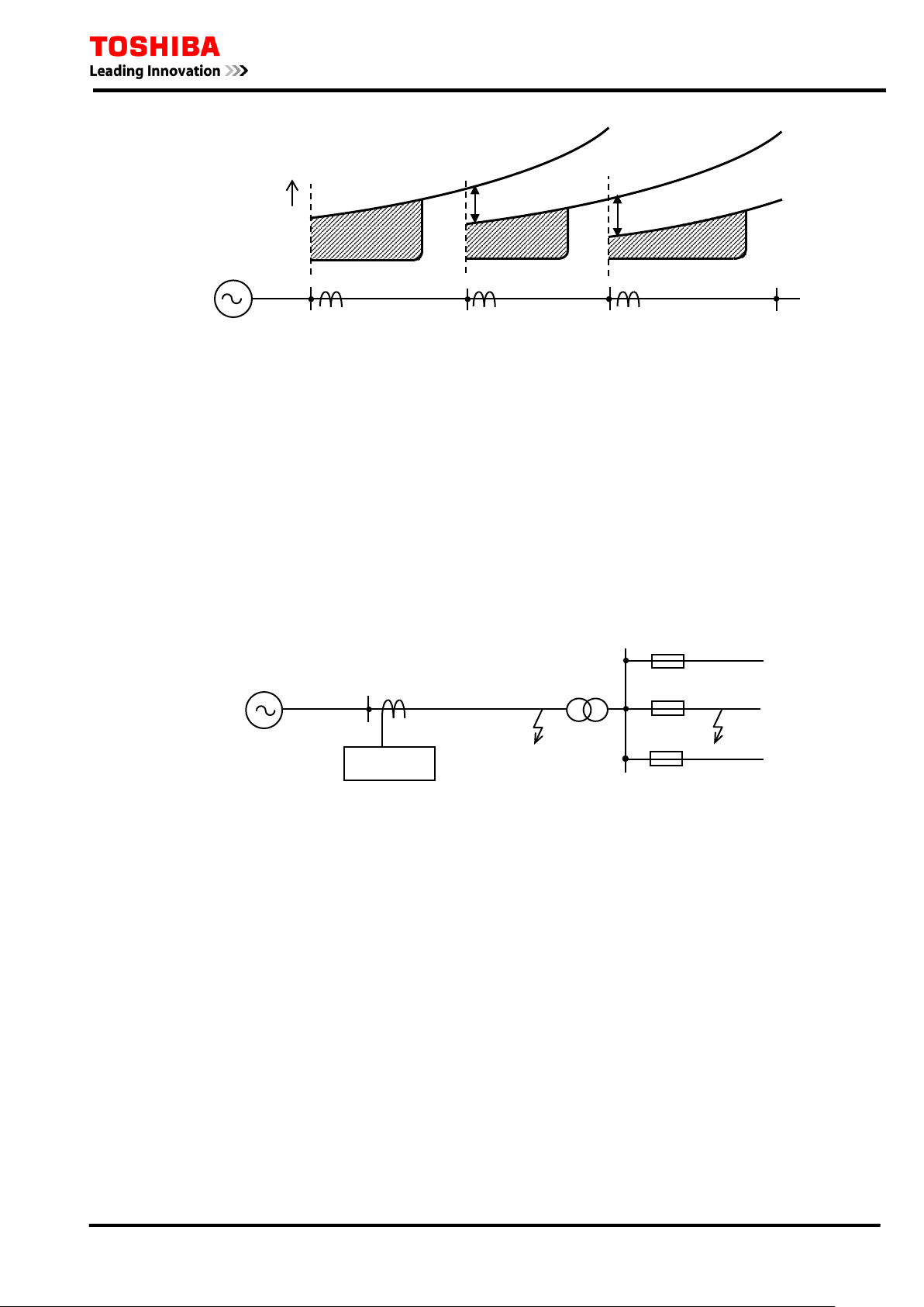
2.2 Instantaneous and Staged Definite Time Overcurrent Protection
In conjunction with inverse time overcurrent protection, definite time overcurrent elements OC2 to
OC4 and EF2 to EF4 provide instantaneous overcurrent protection. OC2 and EF2 also provide the
same inver se ti me protection as OC1 a nd EF1.
OC2 to OC4 and EF2 to EF4 are phase fault and earth fault protection elements, respectively. Each
element is pr ogrammable f or insta ntaneous or definite time delayed operati on. The p hase fa ult
elements opera te on a phase s eg regated basis, a l though t ripp i ng is for thr ee phase only.
2.2.1 Selective Instantaneous Overcurrent P r otecti o n
When they are applied to radial networks with several feeder sections where ZL (impedance of the
protected line) is large enough compared with ZS (the impedance between the rela y and the power
source), and t he magnitu de of the fa ul t cu rr ent in the loca l end fault is much gr eat er (3 t imes or
more, or (ZL+ZS)/ZS≧3 , for ex a mple) t ha n t ha t in the r emote end fa u lt under t he condit ion t ha t
ZS is maximum, t he p ic k-u p c ur r ent ca n b e s et s uf fi cient ly high s o that t he oper a t ing zone of the
elements do not reach the remote end of the feeder, and thus instantaneous and s elective protection
can be applied.
This high setting overcurrent protection is applicable and effective particularly for feeders near the
power source where the setting is feasible, but the longest tripping times would otherwise have to be
accepted.
As long as the associated inverse time overcurrent protection is correctly coordinated, the
instantaneous protection does not requir e s etting coordinat i on with the downstream section.
Figure 2.2.1 s hows operating t imes for instantaneous overcurrent protection in conju nct ion wit h
inverse t ime overcu rrent pr otection. The shaded a rea shows t he reduction in operat ing time by
applying the instantaneous overcurrent protection. The instantaneous protection zo n e d ecreases as
ZS increases.
16
TC
TC
A
B
C
Operate time
Fuse
GRE110
6 F 2 T 0 1 7 2
Figure 2.2.1 Conjunction of Inverse and Instantaneous Overcurrent Protection
The cur r ent sett ing is set 1 .3 to 1 .5 times higher tha n t he prob a ble max imum fau lt c ur rent in the
event of a fault at the remote end. The maximum fault current for elements OC2 to OC4 is obtained
in case of three-phase faults, w hile the m aximum fault current for elements EF2 to EF4 is obtained
in th e even t of s i ngle p hase earth fault s.
2.2.2 Staged Defin ite Time Overcu rr ent P r otecti o n
When app lying i nvers e t ime overcu r r ent protect ion f or a feeder s ys t em as s hown in F i gur e 2.2.2,
well coordinated protection with the fuses in branch circuit faults and high-speed protection for the
feeder faults can be provided by adding staged definite time overcurrent protection with
time-gra ded OC2 and OC3 or EF2 and EF3 elements.
Figure 2.2.2 Feeder Protection Coordinated with Fuses
Configuring the inverse time element O C1 (and EF1 ) and ti me gr aded elements OC 2 and OC3 (or
EF2 and EF3) as shown in Figure 2.2.3, the characteristic of overcurrent protection can be
improved t o c oordinate with the fuse characteristic.
17
Current (amps)
Time (s)
OC2
OC3
Fuse
OC1
≥1
OC2 TRIP
OC2
BLOCK
1
0.00 - 300.00s
&
TOC2
t
0
"IEC"
"IEEE"
+
"ON"
[OC2EN
+
C
B
A
OC2
-D
&
t
0
≥1
&
t
0
≥1
&
C
B
A
&
&
"US"
"C"
≥1
≥1
≥1
&
≥1
106
OC2-A TRIP
107
108
105
OC2-B TRIP
OC2-C TRIP
54
OC2-A
55
56
OC2-B
OC2-C
"D"
OC2
-I
&
[MOC2]
+
[OC2-2F]
ICD
“Block”
6 F 2 T 0 1 7 2
Figure 2.2.3 Staged Def inite T ime Protectio n
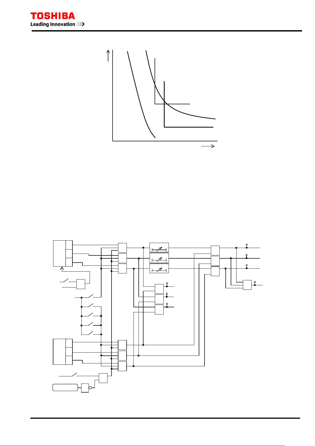
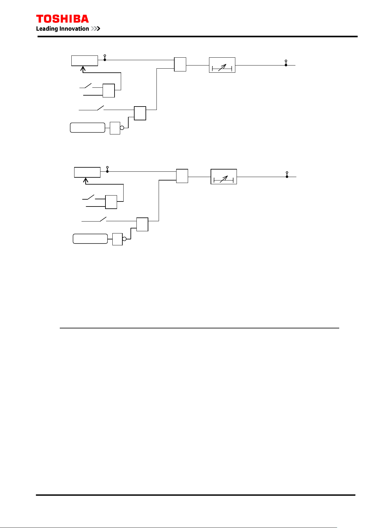
2.2.3 Scheme Logic
As shown in Figure 2. 2.4 to Figu re 2.2.9 , OC2 to OC 4 and EF2 t o EF4 have independent sc heme
logics. OC2 and EF2 provide the same logic of OC1 and EF1. OC3 and EF3 give trip signals OC3
TR IP a nd EF3 TRIP through delayed p i c k-up timers TOC3 and TEF3. OC4 and EF4 are used to
outp ut ala rm signals OC4 ALARM a nd EF4 ALARM. Each t rip a nd alar m can be blocked b y
incorporated scheme switches [OC2EN] to [EF4EN] and binary input signals OC2 BLOCK to EF4
BLOCK. OC*-D and E F*-D elements ca n be also blocked by the s c heme s witches [ OC*-2F] a nd
[EF*-2F]. See Sec tion 2.9.
Figure 2.2.4 Phase Overcurren t P rotection OC2
18
C
B
A
OC3
0.00 - 300.00s
&
&
TOC3
t
0
t
0
t
0
&
OC3 TRIP
OC3-A TRIP
OC3-B TRIP
OC3-C TRIP
≥1
OC3 BLOCK
1
"ON"
[OC3EN]
+
&
110
111
112
57 58
59
109
+
&
[OC3-2F]
ICD
“Block”
C
B
A
OC4
0.00 - 300.00s
&
&
TOC
4
t
0
t
0
t
0
&
OC4
ALARM
OC4-A
ALARM
OC4-B
ALARM
OC4-C
ALARM
≥1
OC4 BLOCK
1
"ON"
[OC4EN]
+
&
114
115
116
60
61
62
113
+
&
[OC4-2F]
ICD
“Block”
EF2-D
≥1
EF2
TRIP
&
0.00 - 300.00s
TEF2
t
0
EF2-I
EF2 BLOCK
1
"ON"
[EF2EN]
+
&
"D"
[MEF2]
"IEC"
"IEEE"
+
"US
"
"C"
&
≥1
118
64
EF1
&
ICD
“Block”
+
[EF2-2F]
6 F 2 T 0 1 7 2
Figure 2.2.5 Phase Overcurren t P rotection OC3
Figure 2.2.6 Phase Overcurren t P rotection OC4
Figure 2.2.7 Earth fault Protection EF2
19
EF3
EF3 TRIP
0.00 - 300.00
s
&
TEF3
t
0
EF3 BLOCK
1
"ON
"
[EF3EN]
+
&
119
65
+
&
[EF3-2F]
ICD
“Block”
EF4
EF4 ALARM
0.00 -
300.00s
&
TEF4
t
0
EF4 BLOCK
1
"ON"
[EF4EN]
+
&
120
66
+
&
[EF4-2F]
ICD
“Block”
6 F 2 T 0 1 7 2
Figure 2.2.8 Earth fault Protection EF3
Figure 2.2.9 Earth fault Protection EF4
2.2.4 Setting
The table shows the setting elements necessary for the instantaneous a nd def ini te time overcu rrent
protection and their setting ranges.
Element Range Step Default Remarks
OC2 0.10 – 25.00 A 0.01 A 5.00 A OC2 threshold setting
TOC2 0.010 – 1.500 0.001 1.000 OC2 ti m e multiplier setting. Required if
[MOC2] = IEC, IEEE, US or C.
0.00 – 300.00 s 0.01 s 0.00 s OC2 definite t ime setting.
TOC2R 0.0 – 300.0 s 0.1 s 0.0 s OC2 definite time delayed reset. Required if
[MOC2] = IEC or if [OC2R] = DEF.
TOC2RM 0.010 – 1.500 0.001 1.000 OC2 dependent time del ayed reset t i m e
multipli er. R equi red i f [ O C 2R ] = D EP .
OC3 0.10 – 150.0 A 0.01 A 10.00 A OC3 threshol d set t ing
TOC3 0.00 – 300.00 s 0.01 s 0.00 s OC3 definite t i me setting.
OC4 0.10 – 150.0 A 0.01 A 10.00 A OC4 threshold setti ng
TOC4 0.00 – 300.00 s 0.01 s 0.00 s OC4definite t i me setting.
EF2 0.05 – 25.00 A 0.01 A 3.00 A EF2 threshold sett i ng
20

Element Range Step Default Remarks
TEF2 0.010 – 1.500 0.001 1.000 EF2 time multipli er setting. Required if
[MEF2] = IEC, IEEE, US or C.
0.00 – 300.00 s 0.01 s 0.00 s EF2 definite time setting.
TEF2R 0.0 – 300. 0 s 0.1 s 0.0 s EF2 defini t e time delayed reset. Requi red if
[MEF2] = IEC or if [EF2R] = DEF.
TEF2RM 0.010 – 1.500 0.001 1.000 EF2 dependent time del ayed reset time
multipli er. R equi red i f [ E F2R ] = D E P.
EF3 0.05 – 100.00 A 0.01 A 5.00 A EF3 t hreshold setting
TEF3 0.00 – 300.00 s 0.01 s 0.00 s EF3 definite time setting.
EF4 0.05 – 100.00 A 0.01 A 5.00 A EF4 threshold setting
TEF4 0.00 – 300.00 s 0.01 s 0.00 s EF4 definite time setting.
[OC2EN] Off / On Off OC2 Enable
[MOC2] D / IEC / IEEE / US / C D OC2 characteristic
6 F 2 T 0 1 7 2
[MOC2C]
MOC2C-IEC
MOC2C-IEEE
MOC2C-US
[OC2R] DEF / DEP DEF OC2 reset characteristic. R equi red i f
[OC2-2F] NA / Block NA OC2 2f block Enable
[OC3EN] Off / On Off OC3 Enable
[OC3-2F] NA / Block NA OC3 2f block Enable
[OC4EN] Off / On Off OC4 Enable
[OC4-2F] NA / Block NA OC4 2f block Enable
[EF2EN] Off / On Off EF2 Enable
[MEF2] D / IEC / IEEE / US / C D EF2 characterist i c
[MEF2C]
MEF2C-IEC
MEF2C-IEEE
MEF2C-US
[EF2R] DEF / DEP DEF OC2 reset characteristic. Required if [MEF2]
NI / VI / EI / LTI
MI / VI / EI
CO2 / CO8
NI / VI / EI / LTI
MI / VI / EI
CO2 / CO8
NI
MI
CO2
NI
MI
CO2
OC2 inverse curve type.
Required if [MO C 2] = IEC.
Required if [MO C 2] = IEEE.
Required if [MO C 2] = U S .
[MOC2] = IEEE or US.
EF2 inverse curve type.
Required if [ME F2] = IEC.
Required if [ME F2] = IEEE.
Required if [ME F2] = US.
= IEEE or US.
[EF2-2F] NA / Block NA EF2 2f block Enable
[EF3EN] Off / On Off EF3 Enable
[EF3-2F] NA / Block NA EF3 2f block Enable
[EF4EN] Off / On Off EF4 Enable
[EF4-2F] NA / Block NA EF4 2f block Enable
21
Ia
Ib
Ic
Ie
TB1
1
2
3
4
5
6
7
8
Ia
Ib
Ic
Residual
current
Ia
Ib
Ic
Ie
TB1
1
2
3
4
5
6
7
8
Ia
Ib
Ic
from
Zero
-phase
current
transformer
Ie
Ie
(
a)
for Residual current
detection wiring
(
b)for Zero-phase current
transformer wiring
Ia
Ib
Ic
Ie
TB1
1
2
3
4
5
6
7
8
from
Zero-
phase
current
transformer
Ie
(
c
)for only Zero
-phase
current transformer wiring
Ia
Ib
Ic
Ie
TB
1
1
2
3
4
5
6
7
8
Ia
Ic
from
Zero-phase
current
transformer
Ie
Ia
Ic
Ia+Ic
Ib=-(Ia+Ic)
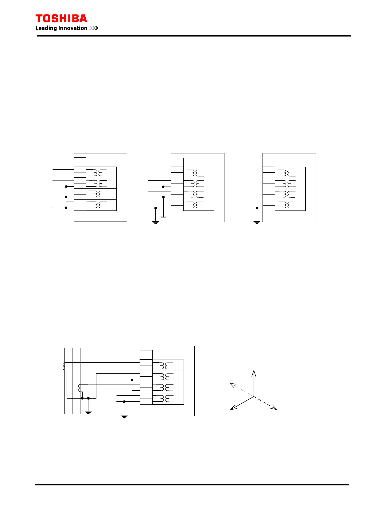
2.2.5 CT Wiring and Setting of earth fault detection
On the models 400, 401 and 402, the earth fault cu rrent i nput ma y be connected either in the
residual circuit of the p hase CTs, or alternatively a dedicated earth fault CT may b e u sed. In t he
case of connection in the residual circuit of the phase CTs, the settings of the phase CT ratio OCCT
and the earth fault CT ratio EFCT should be equal. On the other hand, where a dedicated earth fault
CT or only earth fault CT (no 3 phase CT) are applied, then the settings of OCCT and EFCT may
NOT be equal. The connec tion methods a re illus trated in figu re 2. 2.10.
The maximum setti ng value of t he eart h f ault prot ection is 2 0.00A in c ase of elements EF1 and
EF2, and 100.00A for EF3 and EF4. However, it should be noted that, in the case that a dedicated
ear th fault CT connect ion i s used, the measu ring r ange of earth fault c urrent is limit ed to 20A
maximum.
6 F 2 T 0 1 7 2
Figure 2.2.10 Earth fault current detection wiring
2.2.6 CT Wiring of 2 phase CT
When ap plying 2 phase CT’s for the main circuit, the relay inpu t wiring is as shown in Figure
2.2.11. This wiring derives phase B vector current from phase A and pha se C vector current as
shown in Figure 2.2.12. If zero phase cur rent occur or 3 phase current i s unbalanced, the phase B
current measurement value will not be correct.
When ap plying 2 phase CT’s, the earth fault c urrent inpu t cannot be connect ed to the residual
circ uit of the phas e CT’s. This wiring is N OT for models 820 and 821.
Figure 2.2.11 2 phase CT wiring Figure 2. 2.12 Phase B compo sition of vect ors
22

2.3 Sensitive Earth Fault Protection
The sensitive earth fault (SEF) protection is applied for distribution systems earthed through high
impeda nce, wher e very l ow levels of f au lt cu rr ent ar e exp ected in ear th fau lt s. Fur ther more, the
SEF elements of GRE110 are also appli c able to the “standby ear th fault protection” and t he “high
impedance restricted ea rth fault prot ection of transformers”.
The SEF elements provide more sensit ive s ett ing r a nges (1 mA t o 250mA) tha n the r egula r ear th
fault protection.
Since ver y l ow levels of c urrent set ting may be a pplied, there is a danger of mal-oper a ti on due t o
harmonics of the power system frequency, which can appear as residual current. Therefore the SEF
elements oper ate only on the f undamenta l c omponent, r ejecting all hi gher harmonics.
The SEF protection is provided in Models 420, 421, 422, 820 and 821 which have a dedicated earth
fault input c ircuit.
The element SEF1 provides inverse time or definite time selective two-st age ear th fault protection.
Sta ge 2 of t he t wo-st a ge earth fault protect ion is u sed only f or t he st a ndb y ea r t h fa u lt p r ot ect ion.
SEF2 provides inverse time or definite time selective earth fault protection. SEF3 and SEF4
provi de definite time ear th fault protection.
6 F 2 T 0 1 7 2
When SEF employs IEEE , US or C (C onfigu ra bl e) invers e time cha ra ct eris tics , two r es et modes
are available: definit e time or dependen t ti me res etting. If the IE C invers e time chara cteris tic is
employed, definit e time resetting is provided. For ot her characteris tics, refer to Section 2. 1.1.
In app lications of S EF pr otection, it must be ensu red that any er roneous zero-p hase cu rren t is
suf f iciently low compared to the fau l t current , so that a highly sensitive setting is a vailable.
The err oneous cu rrent may be cau sed with load c urr ent due to unb alanced conf igura tion of t he
distribution lines, or mutual coupling from adjacent lines. The value of the erroneous current during
normal conditions can be ac quired on the metering screen of the relay fr ont pa nel.
The earth fault current for SEF may be fed from a c ore ba lance CT, b ut if it is der ived f rom thr ee
phas e CT s, t he err oneous c ur rent may be ca us ed als o by t he CT er ror in pha s e fa ult s. Transient
false funct i oning may be pr event ed b y a relatively long t i me delay.
Standby earth fault protection
The SE F is energised fr om a C T connec ted in t he power t r a ns for mer low volt a ge neut r a l, a nd t he
standby earth fault protection trips the transformer to backup the low voltage feeder protection, and
ensures that the neutral earthing resistor is not loaded beyond its rating. Stage 1 trips the
transformer low voltage circuit breaker, then stage 2 trips the high voltage circuit breaker(s) with a
time del ay after s tag e 1 operates.
The time graded tripping is valid for transformers connected to a ring bus, banked transformers and
feeder tran sformers.
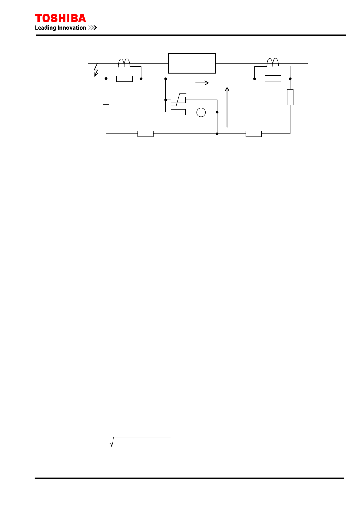
Restricted earth fault protection
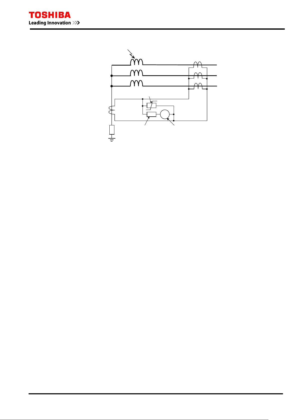
The SEF elements c an be ap plied in a high impeda nce rest ricted ea rth fa ult sc heme (REF), f or
prot ection of a star-connected tr ansfor mer winding whose neut ral is eart hed directly or throu gh
impedance.
As shown in F igur e 2.3. 1, the differ ential c urr ent bet ween the res idual cur rent derived fr om the
three-pha s e f eeder cu rr ents and the neutr a l cur rent in the neutr a l conduc tor is int r oduced int o the
SE F element s. T wo externa l components, a st abilising r esistor and a varis tor, are c onnected as
shown in the fi gure. T he for mer incr ea s es the overa l l impeda nce of t he r ela y circuit and st a bilis es
23
F
Power
Transformer
GRE110
SEF input
Varistor
Stabilising
Resistor
6 F 2 T 0 1 7 2
the differentia l voltage, and the latter sup presses any overvoltage in the differential circuit.
Figure 2.3.1 High Impedance REF
Scheme Logic
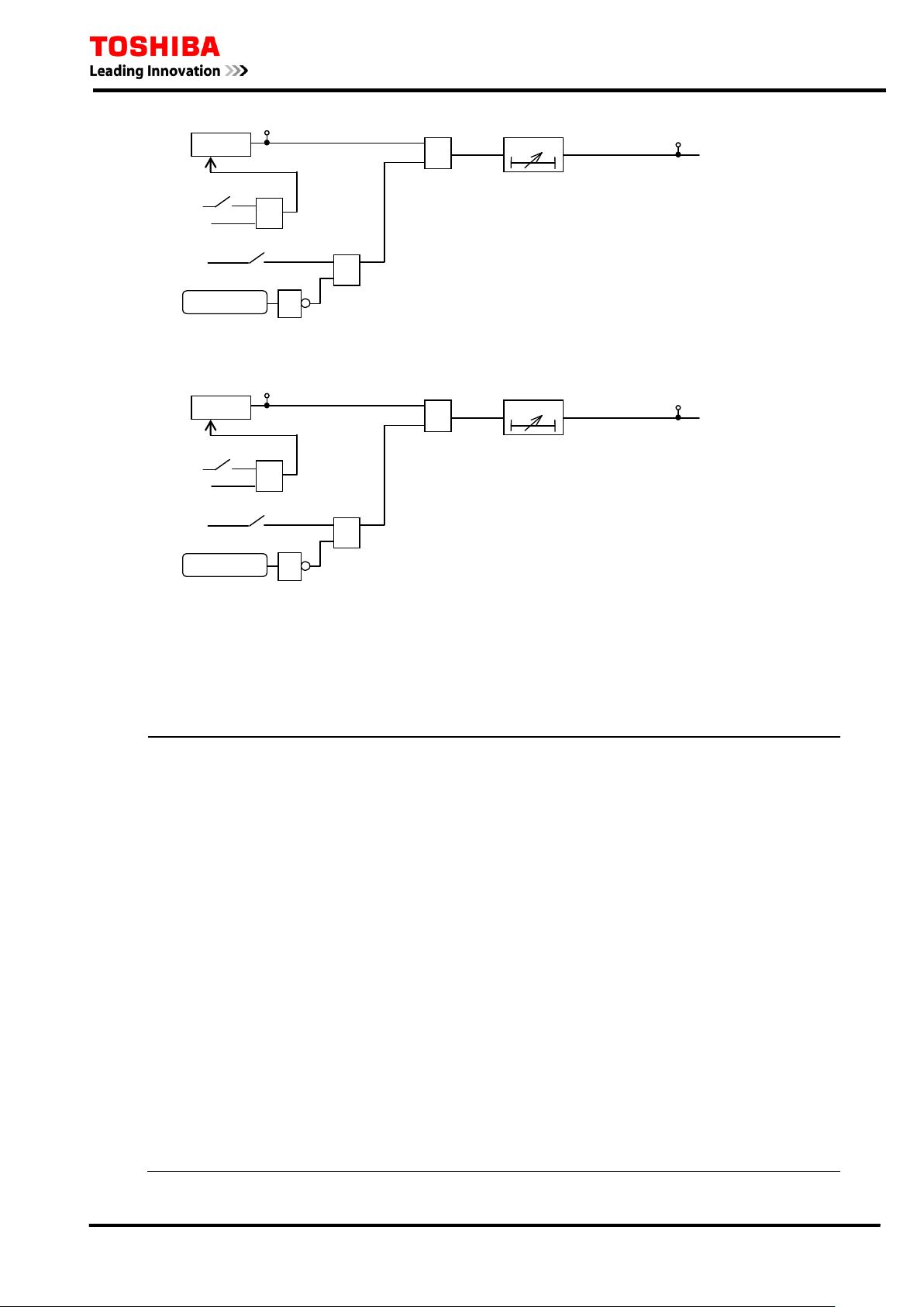
Figure 2. 3.2 to Figu re 2.3.5 show the s c heme logic of inver se time or def in it e t i me sel ec t ive ear t h
fault protect i on and definite t i me earth fault prot ection on model 420, 421 and -422.
In Figures 2.3.2 and 2.3.3, the definite time protection is selected by setting [MSE1] and [MSE2] to
“D”. The element SEF1 is enabled for sensitive earth fault protection and stage 1 trip signal
SEF1-S1 TRIP is given through the delayed pick-up timer TSE1. The element SEF2 is enabled and
tr ip signa l SEF2 TRIP is gi ven through the delayed pick-up timer TSE2.
The in ver se t ime p ro tec ti on is sel ected b y sett ing [M SE 1] a nd [M SE 2] t o either “IEC”, “IEEE”,
“US” or “C” accor ding to the inverse time characteris tic to employ. The element SEF1 is enabled
and stage 1 trip signal SEF1-S1 TRIP is given. The element SEF2 is enabled and trip signal SEF2
TRIP is given.
The S EF 1 protect ion p r ovide s ta ge 2 t r ip signa l S EF 1 -S2 t hr ou gh a dela yed pic k-up timer TSE1
S2.
When the standby earth fault protection is applied by introducing earth current from the
tr ansf ormer low volt age neutr al c ircu it, s ta ge 1 tr ip signa ls a re us ed to tr ip t he tr ansf ormer low
volta ge circu it b rea ker. If SEF 1-D or SEF1-I continu es oper a ting a ft er st a ge 1 has oper at ed, t he
stage 2 trip s ignal ca n be used to trip the tr ansformer high voltage cir c uit breaker ( s).
The signa l SEF1 HS is us ed for b locked overcur rent prot ection and bl ocked busba r prot ection
(r efer to S ection 2.9)
SEF protection can be disabled by the scheme switch [SE1EN] and [SE2EN] or binary input signal
SEF1 BLOCK and SEF2 BLOCK. Stage 2 trip of standby earth fault protection can be disabled by
the scheme sw i tch [ SE1S2].
ICD is the inrush current detector ICD, which detects second harmonic inrush current during
transformer energisation, and can block the SEF*-D element by sheme switch [SE*-2F]. See
Sect ion 2.9
In Figures 2.3.4 and 2.3 .5, S EF3 and S EF4 p rotect ions ar e progr ammable for insta ntaneous or
definite ti me delayed oper a t ions wit h set t ing of dela yed pic k-up timer s T SE 3 a nd T SE4 a nd give
trip signals SEF3 TRIP and SEF4 ALARM.
24
SEF1-D
≥1
SEF1 TRIP
&
0.00 - 300.00s
TSE1
t
0
SEF1HS
SEF1 HS
SEF1-I
SEF1 BLOCK
1
"ON"
[SE1EN]
+
&
"D"
[MSE1]
"IEC"
"IEEE"
+
"US"
"C"
&
≥1
121
67
92
SEF1
SEF1-S2 TRIP
0.00 - 300.00s
&
TS1S2
t
0
+
"ON"
[SE1S2]
122
+
&
SE1-2F]
ICD
“Block”
SEF2-D
≥1
SEF2 TRIP
&
0.00 - 300.00s
TSE2
t
0
SEF2-I
SEF2 BLOCK
1
"ON"
[SE2EN]
+
&
"D"
[MSE2]
"IEC"
"IEEE
"
+
"US"
"C"
&
≥1
123
68
SEF2
+
&
SE2-2F]
ICD
“Block”
6 F 2 T 0 1 7 2
Figure 2.3.2 Inverse T ime or Definite Time SEF Protection SEF1
Figure 2.3.3 Inverse Time or Defin ite Time S E F Protection SEF2
25
SEF3
SEF3 TRIP
0.00 - 300.00s
&
TSE3
t
0
SEF3 BLOCK
1
"ON"
[SE3EN]
+
&
124
69
&
[SE3-2F]
“Block”
+
ICD
SEF4
SEF4
ALARM
0.00 - 300.00s
&
TSE4
t
0
SEF4 BLOCK
1
"ON"
[SE4EN]
+
&
125
70
&
[SE4-2F]
“Block
”
+
ICD
6 F 2 T 0 1 7 2
Figure 2.3.4 Definite Time SEF Protection SEF3
Figure 2.3.5 Definite Time SEF Scheme L ogic
Setting
The ta b le below shows the set ting elements nec essa r y for the sens itive ea rt h fa ul t p r otect ion a nd
their setting ranges .
Element Range Step Default Remarks
SECT 1 - 20000 1 150 CT rati on for sensitive earth fault current
SE1 0.001 – 0.250 A 0.001 A 0.010 A SEF1 threshold sett i ng
TSE1 0.010 – 1.500 0.001 1.000 SEF1 inverse time multiplier setting
0.00 – 300.00 s (*1) 0.01 s 1.00 s SEF1 definite time setting. R equi red if
[MSE1] =DT.
TSE1R 0.0 – 300.0 s 0.1 s 0.0 s SEF1 definite time delayed reset. Required if
[MSE1] =IEC or if [SE1R] = DEF.
TSE1RM 0.010 – 1.500 0.001 1.000 SEF1 dependent time delayed reset ti m e
multipli er. R equi red i f [ S E1R ] = DEP.
TS1S2 0.00 – 300.00 s (*1) 0.01 s 0.00 s SEF1 stage 2 definite tim e set ting
SE2 0.001 – 0.250 A 0.001 A 0.020 A SEF2 threshold sett i ng
TSE2 0.010 – 1.500 0.001 1.000 SEF2 inverse time multiplier setting
0.00 – 300.00 s (*2) 0.01 s 0.00 s SEF2 definite time set ting.
TSE2R 0.0 – 300.0 s 0.1 s 0.0 s SEF2 definite time delayed reset. Required if
[MSE2] =IEC or if [SE2R] = DEF.
TSE2RM 0.010 – 1.500 0.001 1.000 SEF2 dependent time delayed reset ti m e
multipli er. R equi red i f [ S E2R ] = DEP.
26

SE3 0.001 – 0.250 A 0.001 A 0.100 A SEF3 threshold sett i ng
TSE3 0.00 – 300.00 s (*1) 0.01 s 0.00 s SEF3 definite time setting.
SE4 0.001 – 0.250 A 0.001 A 0.250 A SEF4 threshold sett i ng
TSE4 0.00 – 300.00 s (*1) 0.01 s 0.00 s SEF4 definite time setting.
[SE1EN] Off / On On SEF1 Enable
[MSE1] DT / IEC / IEEE / US / C D SEF1 characteristic
6 F 2 T 0 1 7 2
[MSE1C]
MSE1C-IEC
MSE1C-IEEE
MSE1C-US
[SE1R] DEF / DEP DEF SEF1 reset characterist i c. R equi red i f
[SE1S2] Off / On Off SEF1 stage 2 ti m er enable
[SE2EN] Off / On Off SEF2 Enable
[MSE2] DT / IEC / IEEE / US / C D SEF2 characteristic
[MSE2C]
MSE2C-IEC
MSE2C-IEEE
MSE2C-US
[SE2R] DEF / DEP DEF SEF2 reset characterist i c. R equi red i f
[SE3EN] Off / On Off SEF3 Enable
[SE4EN] Off / On Off SEF4 Enable
(*1) Time setting of TSE1 – TSE4 should be set in consideration of the SEF drop-off time
NI / VI / EI / LTI
MI / VI / EI
CO2 / CO8
NI / VI / EI / LTI
MI / VI / EI
CO2 / CO8
80-100ms.
NI
MI
CO2
NI
MI
CO2
SEF1 inverse curve type.
Required if [MS E1] = IEC.
Required if [MS E1] = IEEE.
Required if [MS E1] = US.
[MSE1] = IEEE or US.
SEF2 inverse curve type.
Required if [MS E2] = IEC.
Required if [MS E2] = IEEE.
Required if [MS E2] = US.
[MSE2] = IEEE or US.
SEF
SEF is s et s ma ller t ha n the a va il a ble ea r t h fa u lt cu r r ent a nd la r ger tha n t he er r oneou s zer o-phase
cur r ent . T he er ro neou s zer o-ph as e cur r ent ex ist s under normal c onditions du e to the unb ala nced
feeder configuration. The zero-phase current is normally fed from a core balance CT on the feeder,
but if it is derived from three phase CTs, the erroneous current may be caused also by the CT error
in pha se faults.
The erroneous stead y state zero-p hase cu rrent can b e acquired on the meter ing screen of t he relay
front panel.
High impedance REF protection
CT sa t urat ion under thr ou gh fa ul t condit ions res u lts in vol ta ge a p pea r i ng a cr os s the r ela y c ir cu it .
The volt a ge set ti ng of the rela y cir cu it must be arra nged s u ch t ha t it is great er than the max imum
voltage that c an occu r under thr ough f au lt condit ions. T he wors t ca s e is cons idered wher eby one
CT of the balancing group becomes completely saturated, while the others maintain linear
operation. The excitation impedance of the saturated CT is considered to approximate a
short-circuit.
27
VS
IF
Saturated CT
Healthy CT
RCT
RL
ZM?0
RS
GRE110
Varistor
Transformer
Circuit
Stabilising
Resistor
( )
2 × × −V I R V
k F S k
ZM≈0
6 F 2 T 0 1 7 2
Figure 2.3.4 Maximum Voltage under Through Fault Condition
The volt age across the rela y c i rcuit under these conditions is given by the equat i on:
V
= IF×(RCT + RL)
S
where:
= critical setting voltage (rms)
V
S
I
= maximum prospective s ec ondary through fault current (rms)
F
R
= C T secondary winding resistance
CT
R
= Lead resistance (total resistance of the loop from the saturated CT to the relaying point)
L
A series stabilising resistor is used to rai se the voltage setti ng of the rela y c ircuit to Vs. No s a f ety
margin is needed since the extr eme ass umption of unb alanced CT satu ration does not occur in
pract ice. The ser i es resis tor v alu e, Rs, is selected a s follows:
= VS / IS
R
S
Is is the current setting (in secondary amps) applied to the GRE110 relay. Howe v e r, the actual faul t
sett i ng of the scheme includes the total current flowing in all p ara llel p aths. That is to sa y that the
actual primary current for operation, after being referred to the secondary circuit, is the sum of the
rela y operat ing curr ent, t he curr ent flowing in the va rist or, a nd the excita tion cur rent of all the
par all el connected CTs at the setting voltage. In pra ctice, the varistor cur rent is nor mally small
enough that it c an be neglected. Hence:
≦ IP / N – 4I
I
S
mag
where:
= setting a pplied to G RE110 rela y ( secondary amps )
I
S
I
= minimum primary c urrent for operation (eart h f ault sensitivi ty)
P
N = CT ratio
I
= CT magnetising (exci tat ion) cur rent a t voltage VS
mag
Mor e s ens i tive sett i ngs for I s allow for greater cover age of the t rans former winding, but they also
require larger values of Rs to ensure stability, and the increased impedance of the differential circuit
can result in high voltages being developed during internal faults. The peak voltage, Vpk, developed
may be a pproximated b y the equation:
V
= 2×
pk
where:
28

6 F 2 T 0 1 7 2
Vk = C T knee point voltage
I
= maximum prospective s ec ondary current for an int ernal fault
F
When a Metrosil is used for the varist or, it should be selected with the following characteristics:
V = CI
β
where:
V = instantaneous vol tage
I = ins tant aneous c urrent
β = c onsta nt, nor mally in the r ange 0. 20 - 0.25
C = c onsta nt.
The C value defines the cha ract eristics of the metrosi l, and shou ld be chosen according to the
following r equ irements:
1. The current through the metrosil at the relay voltage setting should be as low as possible,
preferably less than 30mA for a 1Amp CT and less than 100mA for a 5Amp CT.
2. The voltage at the maximum secondary c urrent shoul d be limited, preferably to 1500Vrms.
Restricted earth fault schemes should be applied with high accuracy CTs whose knee point voltage
V
is chosen according to t he equ ation:
k
V
where V
≧ 2×VS
k
is t he dif f erentia l sta bility volt age setting for the scheme.
S
Diretctional Sensitive Earth fault protection (at model 820 and 821)
The models 82 0 and 8 21 a r e espet ia ly models for the directional sensit ive eart h fault prot ection
using eart h f ault current a nd z ero pha se volta ge at t he non- grounding system,.
Figure 2.3.5 illu str at es the dir ectional char act erist ic, wit h the for war d opera te zone sha ded. T he
revers e zone is s imply a mirr or image of t he forwa r d zone. The forwa rd op erat e zone or reverse
operate zone is selectable by the scheme switch [SE-DIR] As shown in Figure 2.3.6, the directional
characteristic is composed of a forward directional characteristic, reverse directional characteristic
and over c urrent thresholds.
Polarising signals for dir ect ional elements ar e shown in F igur e 2. 3.7. Polarisation for dir ectional
sensiti v e ear th fault element SEF is der i ved from a residual volta ge.
Figures 2.3.8 to 2.3.11 show t he scheme logic for the dir ectiona l sens itive ea rt h fa ult pr otect ion.
The directiona l contr ol cha r ac ter ist ic ca n b e select ed t o “FWD” or “REV” or “Non” by s cheme
switc h setting [ SE∗-DIR].
At the model 820 and 821, the directional sensitive earth fault elements ca n be configured for
direct ional op erat ion in the sa me way as the st andar d earth fa ult pole, by pola rising a gainst the
residu al volta ge. An a dditiona l r est ra int on opera t ion ca n be pr ovided by a Z ero p has e sequ ence
Power elemen t ZP, for u se in pr otection of power s ystems which u tilise r esona nt (Pet ersen coil )
ear thing methods.
29
 Loading...