

Toshiba GRD150, GRD150-10 Series, GRD150-20 Series, GRD150-30 Series, GRD150-40 Series User Manual
GRD150
2
FEATURES
Protection functions
Non-directional and directional overcurrent and
earth-fault protection and sensitive earth fault
protection (option)
Overvoltage and undervoltage protection
Thermal overload protection
Underfrequency or overfrequency protection
Negative phase sequence overcurrent
protection
Undercurrent protection
Circuit breaker failure protection
Autoreclose function (option)
Control functions
Indication of the status of switching devices, i.e.
circuit breakers and disconnectors
Open and close commands for switching
devices
Synchronism check function (option)
MIMIC configuration display
Monitoring and Metering
Circuit breaker condition monitoring
Trip circuit supervision
Metering: three-phase currents and voltages,
residual current and voltage, frequency, active
and reactive power, power factor, and max.
demand values.
Recording
Event record: 480 most recent events
Alarm record: 32 most recent alarms
Fault record: 8 most recent faults
Disturbance record: 9 analog and 32 binary
signals
User Interface
Menu-based HMI system
Graphical LCD display
PLC function
Configurable binary inputs and outputs
Configurable LED indications
Communication Interface: RS485, Fibre optic
or Ethernet LAN (option)
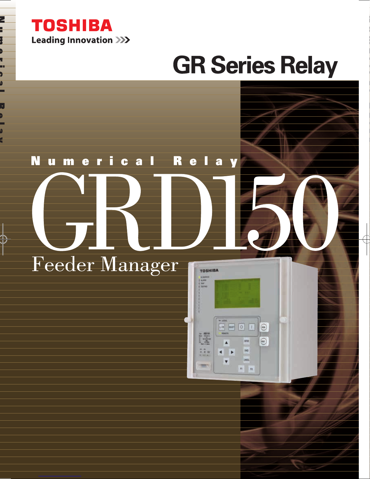
APPLICATION
GRD150 feeder manager is designed for protection,
control, metering and supervision of medium voltage
networks.
GRD150 includes multiple, high accuracy, overcurrent
protection elements (for phase and/or earth fault) with
inverse time (IDMTL) and definite time delay (DTL)
functions. All phase, earth and sensitive earth fault
overcurrent elements can be independently subject to
directional control. The directional elements provide
user-settable characteristic angles.
Other protection functions are also available, including
thermal protection to IEC60255-8, negative sequence
overcurrent protection, under/overvoltage and under/
over frequency protections.
GRD150 provides continuous monitoring of internal
circuits and of software. External circuits are also
monitored, by trip circuit supervision, CT and VT
supervision, and CB condition monitoring features.
A user-friendly HMI is provided through a backlit LCD,
programmable LEDs, keypad and menu-based
operating system. PC access is also provided, either
for local connection via a front-mounted RS232 port,
or for remote connection via a rear-mounted RS485
or fibre optic port. The communication system allows
the user to read and modify the relay settings, and to
access data gathered by the relay’s metering and
recording functions.
Data available either via the relay HMI or communications
ports includes the following functions.
Metering
Fault recording
Event recording
Alarm recording
Disturbance recording (available via
communications ports)
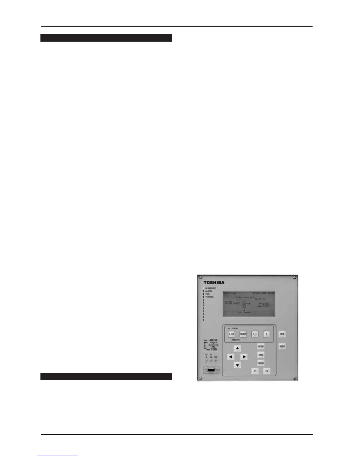
Figure 1 - Front View

GRD150
3
Table 1 GRD150 models and Functions
GRD150- Models
Function
10∗ series 20∗ series 30∗ series 40∗ series
Non-directional overcurrent OC (IDMTL, DTL, INST)
Non-directional earth fault EF (IDMTL, DTL, INST)
Non-directional sensitive earth fault SEF (IDMTL, DTL, INST)
Directional overcurrent DOC (IDMTL, DTL, INST)
Directional earth fault DEF (IDMTL, DTL, INST)
Directional sensitive earth fault DSEF (IDMTL, DTL, INST)
Undercurrent UC
Thermal over load THM
Non-directional negative phase overcurrent NOC (IDMTL, DTL, INST)
Directional negative phase overcurrent DNOC (IDMTL, DTL, INST)
Broken conductor detection BCD
Circuit breaker failure protection CBF
Cold load pick-up feature
Overvoltage OV (IDMTL, DTL, INST)
Undervoltage UV (IDMTL, DTL, INST)
Zero phase sequence overvoltage ZOV (IDMTL, DTL, INST)
Negative phase sequence overvoltage NOV (IDMTL, DTL, INST)
Under/over frequency FRQ
Autoreclose function
Fault locator
Indication of the status of switching devices
Open and close commands for switching devices
Synchronism check function
MIMIC configuration picture (*)
PLC function (*)
CT supervision
VT supervision
Trip circuit supervision
Self supervision
CB state monitoring
Trip counter alarm
∑Iy alarm
CB operate time alarm
Multiple settings groups
Metering
Fault records
Alarm records
Event records
Disturbance records
Communication
IDMTL: inverse definite minimum time
DTL: definite time
INST: instantaneous
(*): PC tools (MIMIC editor and PLC editor) are option.

GRD150
4
FUNCTIONS
Protection
- 4-stage non-directional and directional overcurrent
and earth-fault protection and sensitive earth fault
protection (option)
1
st
and 2nd stage: Instantaneous, IDMTL or DTL
3
rd
and 4th stage: Instantaneous or DTL
- 2-stage non-directional and directional negative
phase sequence overcurrent protection
1
st
stage: Instantaneous, IDMTL or DTL
2
nd
stage: Instantaneous or DTL
- 2-stage overvoltage and undervoltage protection
1
st
stage: Instantaneous, IDMTL or DTL
2
nd
stage: Instantaneous or DTL
- 6-stage underfrequency or overfrequency protection
- Thermal overload protection
- Cold load protection function or Inrush current (2
nd
harmonic) detector provided for energising the
system
- Undercurrent protection
- Broken conductor detection
- Circuit breaker failure protection
- Autoreclose function: 5-shots, 3-phase autoreclose
(option)
Control
Two-stepped operation (select-control) is used for the
control procedure of circuit breakers, disconnectors,
earthing disconnector switches and transformers to
ensure highly reliable operation.
- Control of circuit breakers, disconnectors and
earthing disconnector switches
- Interlock check
- Synchronism check for circuit breaker closing
(option)
- MIMIC configuration picture displayed on LCD
- Double command blocking
- Switchgear operation counter
- Control blocking
Password protection is provided to operate above
functions.
Monitoring and Metering
- Status monitoring of switchgear devices and failure
monitoring of power apparatus, control equipment,
protection relays and ancillary equipment
- Metering: current, voltage, frequency, active power,
reactive power and max. demand values
An energy calculation (Watt-hour, var-hour) is also
available.
- Limit value checking of metering
- Opening and closing time monitoring
These data are available on the HMI and at a local or
remote PC.
Recording
- Event records: The most recent 480 time-tagged
events with 1ms resolution are stored.
- Alarm records: The most recent 32 time-tagged
alarms with 1ms resolution are stored.
- Fault records: The most recent 8 time-tagged faults
with 1ms resolution are stored.
- Disturbance records: GRD150 can record 9 analog
and 32 binary signals, initiated by relay tripping. Pretrigger and post-trigger recording times can be set,
and the maximum number of records which can be
stored is dependent on the recording times chosen.
These records are available on the HMI and at a local
or remote PC.
GRD150
5
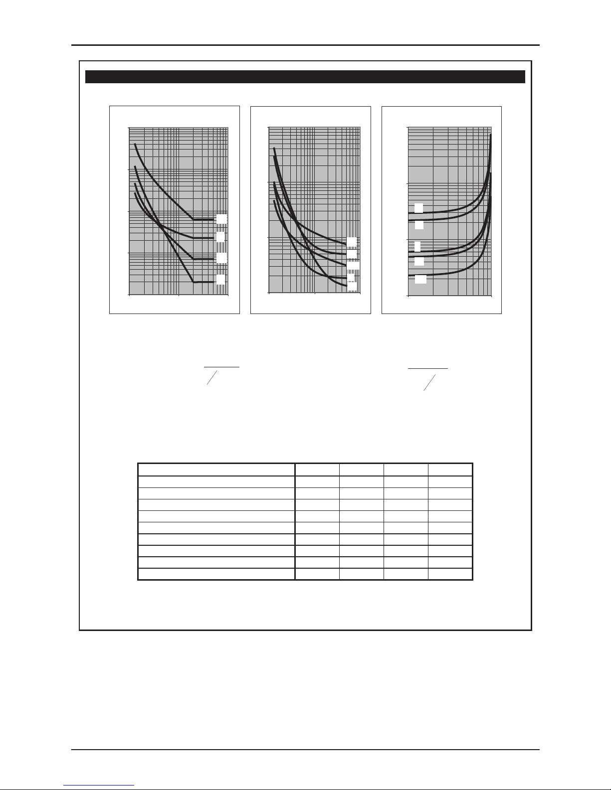
Figure 2 - Operate and Reset Characteristics of IDMTL
Inverse Time Operate and Reset Curves
IEC/UK Inverse Curves
(Time Muliplier TMS = 1)
0.1
1
10
100
1000
1 10 100
Current (Multiple of Setting)
Operating Time (s)
LTI
NI
VI
EI
IEEE/US Inverse Curves
(Time Multiplier TMS = 1)
0.1
1
10
100
1 10 100
Current (Multiple of S etting)
Operating Time (s)
MI
VI
STI
I
EI
IEEE/US Reset Curves
(Time Multiplier T MS = 1)
1.00
10.00
100.00
1000.00
0.1 1
Current (Multiple of S etting)
Time (s)
MI
VI
EI
STI
I
()
⎪
⎭
⎪
⎬
⎫
⎪
⎩
⎪
⎨
⎧
+
⎥
⎥
⎥
⎦
⎤
⎢
⎢
⎢
⎣
⎡
−
×= c
Is
I
k
TMSt
1
α
⎥
⎥
⎥
⎥
⎦
⎤
⎢
⎢
⎢
⎢
⎣
⎡
⎟
⎠
⎞
⎜
⎝
⎛
−
×=
2
1
S
r
I
I
t
RTMSt
Inverse time operate function Dependent time reset function
Constants for dependent time curves
Curve Description k
α
C t
r
IEC Normal Inverse (NI)
0.14 0.02 0 -
IEC Very Inverse (VI)
13.5 1 0 -
IEC Extremely Inverse (EI)
80 2 0 -
UK Long Time Inverse (LTI)
120 1 0 -
IEEE Moderately Inverse (MI)
0.0515 0.02 0.114 4.85
IEEE Very Inverse (VI)
19.61 2 0.491 21.6
IEEE Extremely Inverse (EI)
28.2 2 0.1217 29.1
US CO8 Inverse (I)
5.95 2 0.18 5.95
US CO2 Short Time Inverse (STI)
0.02394 0.02 0.01694 2.261
GRD150
6
USER INTERFACE
Relay Front Panel
A user friendly interface is provided on the relay front
panel. A menu-based system provides for easy
programming of relay functions and access to realtime and stored data. The front panel includes the
following features.
Graphical LCD
display with backlight.
12 LEDs including 8
user programmable
LEDs.
Keypad.
RS232C serial port for connection of local PC.
Local PC Connection
The user can communicate with the GRD150 from a
local PC via the RS232C port on the front panel. Using
RSM100 software, the user can view and modify
settings, monitor real-time metering and analyse
recorded data.
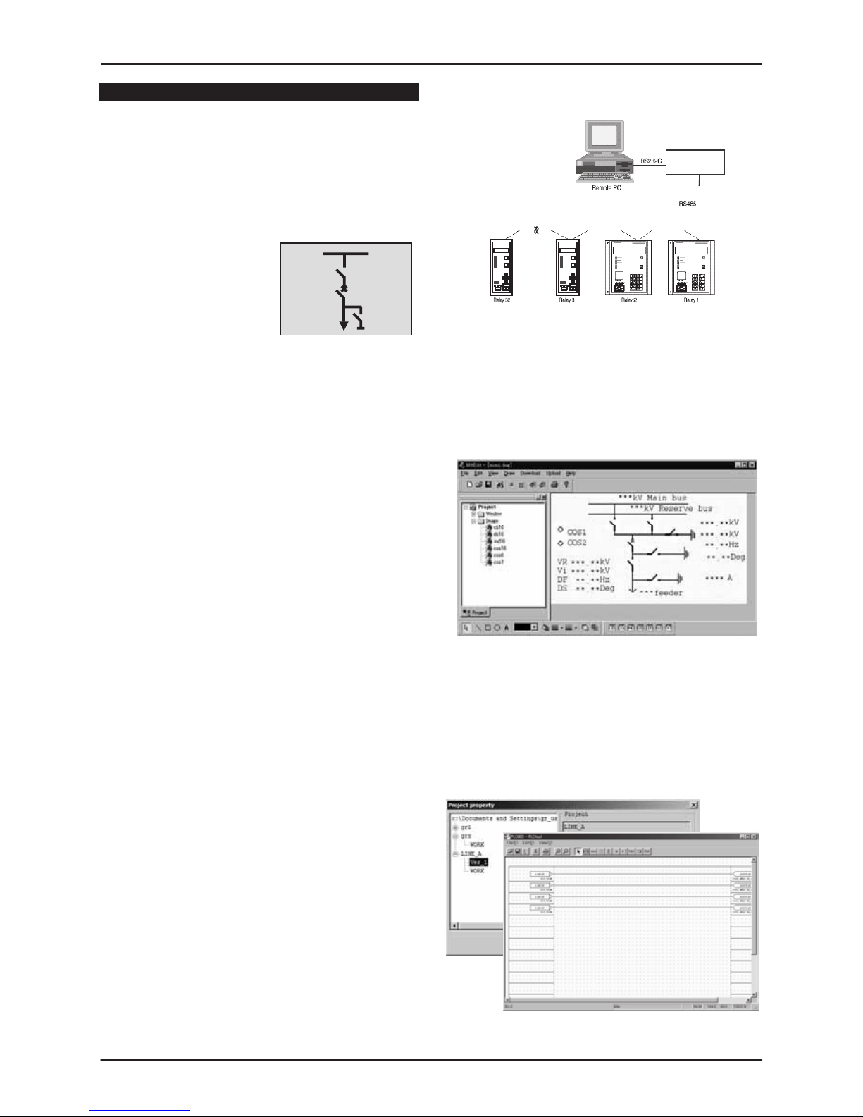
Relay Setting and Monitoring (RSM)
and Remote Control System
GRD150 can be connected to the RSM system via
the rear mounted serial communications port, using
RS485 or other connections such as fibre optic,
Ethernet LAN, etc., (specified at time of order). Using
RSM100 software, the user can view and modify
settings, monitor real-time metering and analyse
recorded data.
A maximum of 32 relays can be connected to the
remote PC in multi-drop mode, by connection via a
protocol converter, with data transmission rate of
64kbps using RSM-X protocol. Modbus®(RTU) protocol
can be also available.
The figures below show the configuration of the RSM
system and typical displays from the RSM100 software.
Using an additional port (option), GRD150 can be
connected to a Substation Control System. In this
case, GRD150 supports IEC60870-5-103 or DNP3.0
transmission protocols.
Figure 3 - Relay Setting and Monitoring System
Mimic Editor (MMEdit)
Yhe user can configure and customize the MIMIC
data displayed on the LCD of GRD150 using
MMEdit software. The MIMIC data produced by the
MMEdit software can be uploaded to GRD150 via the
PC communication port (RS232C).
Figure 4 - PC Display of MMEdit
PLC Editor (PLCEdit)
The user can customize logic functions on GRD150
such as trip and interlock sequence, etc., using
PLCEdit software. The PLC data produced by the
PLCEdit software can be uploaded to GRD150 via PC
communication port (RS232C).
Figure 5 - PC Display of PLCEdit
Converter
G1PR2

GRD150
7
Figure 6 - Relay Setting and Monitoring System - PC Displays
PC DISPLAY
Status (Metering) Record (Alarm record)
Setting Record (disturbance record: data analysis)
Status: display measurement values of power system quantities and status of relay element, etc.
Setting: change settings of protection relay and control function, etc.
Record: display fault record, event record, alarm record and disturbance record.

GRD150
8
TECHNICAL DATA
Ratings
AC current In 1A or 5A
AC voltage Vn: 100V to 120V
Frequency: 50Hz or 60Hz
DC auxiliary supply: 110/125Vdc (Operative range: 88 – 150Vdc),
220/250Vdc (Operative range: 176 – 300Vdc),
48/54/60Vdc, (Operative range: 38.4 – 72Vdc)
Superimposed AC ripple on DC supply: ≤ 12%
DC supply interruption: ≤ 50ms at 110V
Binary input circuit DC voltage: 110/125Vdc,
220/250Vdc,
48/54/60Vdc
Overload Ratings
AC current inputs: 3 times rated current continuous
100 times rated current for 1 second
AC voltage inputs: 2 times rated voltage continuous
Burden
AC phase current inputs: ≤ 0.1VA (1A rating)
≤ 0.3VA (5A rating)
AC earth current inputs: ≤ 0.3VA (1A rating)
≤ 0.4VA (5A rating)
AC sensitive earth inputs: ≤ 0.3VA (1A rating)
≤ 0.4VA (5A rating)
AC voltage inputs: ≤ 0.1VA (at rated voltage)
DC power supply: ≤ 15W (quiescent)
≤ 20W (maximum)
Binary input circuit: ≤ 0.5W per input at 110Vdc
Protection Functions
Current Transformer Requirements
Phase Inputs Typically 5P20 with rated burden according to load, (refer to
manual for detailed instructions).
Standard Earth Inputs: Core balance CT or residual connection of phase CTs.
Sensitive Earth Inputs: Core balance CT.
Non-directional Phase Overcurrent Protection
OC 1st Overcurrent threshold: OFF, 0.04 – 5.00A in 0.01A steps (1A rating)
OFF, 0.2 – 25.0A in 0.1A steps (5A rating)
OC 2nd Overcurrent threshold: OFF, 0.10 – 50.00A in 0.01A steps (1A rating)
OFF, 0.5 – 250.0A in 0.1A steps (5A rating)
Delay type: DTL, IEC NI, IEC VI, IEC EI, UK LTI, IEEE MI,
IEEE VI, IEEE EI, US CO8 I, US CO2 STI, User SI
IDMTL Time Multiplier Setting TMS: 0.010 – 1.500 in 0.001 steps
DTL delay: Inst, 0.01 – 300.00s in 0.01s steps
Reset Type: Definite Time or Dependent Time.
Reset Definite Delay: Instantaneous, 0.1 – 300.0s in 0.1s steps
Reset Time Multiplier Setting RTMS: 0.010 – 1.500 in 0.001 steps
OC 3rd, 4th Overcurrent thresholds: OFF, 0.10 – 50.00A in 0.01A steps (1A rating)
OFF, 0.5 – 250.0A in 0.1A steps (5A rating)
DTL delay: Inst, 0.01 – 300.00s in 0.01s steps

GRD150
9
Non-directional Earth Fault Protection
EF 1st Overcurrent threshold: OFF, 0.01 – 5.00A in 0.01A steps (1A rating)
OFF, 0.05 – 25.00A in 0.01A steps (5A rating)
EF 2nd Overcurrent threshold: OFF, 0.04 – 50.00A in 0.01A steps (1A rating)
OFF, 0.2 – 250.0A in 0.1A steps (5A rating)
Delay type: DTL, IEC NI, IEC VI, IEC EI, UK LTI, IEEE MI,
IEEE VI, IEEE EI, US CO8 I, US CO2 STI, User SI
IDMTL Time Multiplier Setting TMS: 0.010 – 1.500 in 0.001 steps
DTL delay: Inst, 0.01 – 300.00s in 0.01s steps
Reset Type: Definite Time or Dependent Time.
Reset Definite Delay: Instantaneous, 0.1 – 300.0s in 0.1s steps
Reset Time Multiplier Setting RTMS: 0.010 – 1.500 in 0.001 steps
EF 3rd, 4th thresholds: OFF, 0.04 – 50.00A in 0.01A steps (1A rating)
OFF, 0.2 – 250.0A in 0.1A steps (5A rating)
DTL delay: Inst, 0.01 – 300.00s in 0.01s steps
Non-directional Sensitive Earth Fault Protection (Option)
SEF 1st, 2nd Overcurrent threshold: OFF, 0.005 – 0.025A in 0.001A steps (1A rating)
OFF, 0.025 – 0.125A in 0.001A steps (5A rating)
Delay Type: DTL, IEC NI, IEC VI, IEC EI, UK LTI, IEEE MI,
IEEE VI, IEEE EI, US CO8 I, US CO2 STI, User SI
IDMTL Time Multiplier Setting TMS: 0.010 – 1.500 in 0.001 steps
DTL delay: Inst, 0.01 – 300.00s in 0.01s steps
Reset Type: Definite Time or Dependent Time.
Reset Definite Delay: Instantaneous, 0.1 – 300.0s in 0.1s steps
Reset Time Multiplier Setting RTMS: 0.010 – 1.500 in 0.001 steps
SEF 3rd, 4th thresholds: OFF, 0.005 – 0.025A in 0.001A steps (1A rating)
OFF, 0.025 – 0.125A in 0.001A steps (5A rating)
DTL delay: Inst, 0.01 – 300.00s in 0.01s steps
Non-directional Negative Phase Sequence Overcurrent Protection
NOC 1st overcurrent threshold: OFF, 0.10 – 2.00A in 0.01A steps (1A rating)
OFF, 0.5 – 10.0A in 0.1A steps (5A rating)
Delay type (1st threshold only): DTL, IEC NI, IEC VI, IEC EI, UK LTI, IEEE MI,
IEEE VI, IEEE EI, US CO8 I, US CO2 STI, User SI
IDMTL Time Multiplier Setting TMS: 0.010 – 1.500 in 0.001steps
DTL delay: Inst, 0.01 – 300.00s in 0.01s steps
Reset Type: Definite Time or Dependent Time.
Reset Definite Delay: Instantaneous, 0.1 – 300.0s in 0.1s steps
Reset Time Multiplier Setting RTMS: 0.010 − 1.500 in 0.001 steps
DTL delay: Inst, 0.01 – 300.00s in 0.01s steps

GRD150
10
Directional Phase Overcurrent Protection
DOC 1st Overcurrent threshold: OFF, 0.04 – 5.00A in 0.01A steps (1A rating)
OFF, 0.2 – 25.0A in 0.1A steps (5A rating)
DOC 2nd Overcurrent threshold: OFF, 0.10 – 50.00A in 0.01A steps (1A rating)
OFF, 0.5 – 250.0A in 0.1A steps (5A rating)
Delay type: DTL, IEC NI, IEC VI, IEC EI, UK LTI, IEEE MI,
IEEE VI, IEEE EI, US CO8 I, US CO2 STI, User SI
IDMTL Time Multiplier Setting TMS: 0.010 – 1.500 in 0.001 steps
DTL delay: Inst, 0.01 – 300.00s in 0.01s steps
Reset Type: Definite Time or Dependent Time.
Reset Definite Delay: Instantaneous, 0.1 – 300.0s in 0.1s steps
Reset Time Multiplier Setting RTMS: 0.010 – 1.500 in 0.001 steps
DOC 3rd, 4th Overcurrent thresholds: OFF, 0.10 – 50.00A in 0.01A steps (1A rating)
OFF, 0.5 – 250.0A in 0.1A steps (5A rating)
DTL delay: Inst, 0.01 – 300.00s in 0.01s steps
DOC Characteristic Angle: −95° to +95° in 1° steps
Directional Earth Fault Protection
DEF 1st Overcurrent threshold: OFF, 0.01 – 5.00A in 0.01A steps (1A rating)
OFF, 0.05 – 25.00A in 0.01A steps (5A rating)
DEF 2nd Overcurrent threshold: OFF, 0.04 – 50.00A in 0.01A steps (1A rating)
OFF, 0.2 – 250.0A in 0.1A steps (5A rating)
Delay type: DTL, IEC NI, IEC VI, IEC EI, UK LTI, IEEE MI,
IEEE VI, IEEE EI, US CO8 I, US CO2 STI, User SI
IDMTL Time Multiplier Setting TMS: 0.010 – 1.500 in 0.001 steps
DTL delay: Inst, 0.01 – 300.00s in 0.01s steps
Reset Type: Definite Time or Dependent Time.
Reset Definite Delay: Instantaneous, 0.1 – 300.0s in 0.1s steps
Reset Time Multiplier Setting RTMS: 0.010 – 1.500 in 0.001 steps
DEF 3rd, 4th thresholds: OFF, 0.04 – 50.00A in 0.01A steps (1A rating)
OFF, 0.2 – 250.0A in 0.1A steps (5A rating)
DTL delay: Inst, 0.01 – 300.00s in 0.01s steps
DEF Characteristic angle: −95° to +95° in 1° steps
DEF Voltage threshold: 0.5 – 100.0V in 0.1V steps
Directional Sensitive Earth Fault Protection (Option)
DSEF 1st, 2nd Overcurrent threshold: OFF, 0.005 – 0.025A in 0.001A steps (1A rating)
OFF, 0.025 – 0.125A in 0.001A steps (5A rating)
Delay Type: DTL, IEC NI, IEC VI, IEC EI, UK LTI, IEEE MI,
IEEE VI, IEEE EI, US CO8 I, US CO2 STI, User SI
IDMTL Time Multiplier Setting TMS: 0.010 – 1.500 in 0.001 steps
DTL delay: Inst, 0.01 – 300.00s in 0.01s steps
Reset Type: Definite Time or Dependent Time
Reset Definite Delay: Instantaneous, 0.1 – 300.0s in 0.1s steps
Reset Time Multiplier Setting RTMS: 0.010 – 1.500 in 0.001 steps
DSEF 3rd, 4th thresholds: OFF, 0.005 – 0.025A in 0.001A steps (1A rating)
OFF, 0.025 – 0.125A in 0.001A steps (5A rating)
DTL delay: Inst, 0.01 – 300.00s in 0.01s steps
DSEF Characteristic angle: −95° to +95° in 1° steps
DSEF Boundary of operation: ±87.5°
DSEF Voltage threshold: 0.5 – 100.0V in 0.1V steps
Residual power threshold: OFF, 0.00 – 20.00W in 0.05W (1A rating)
OFF, 0.00 – 100.00W in 0.25W (5A rating)

GRD150
11
Directional Negative Phase Sequence Overcurrent Protection
DNOC 1st overcurrent threshold: OFF, 0.10 – 2.00A in 0.01A steps (1A rating)
OFF, 0.5 – 10.0A in 0.1A steps (5A rating)
Delay type (1st threshold only): DTL, IEC NI, IEC VI, IEC EI, UK LTI, IEEE MI,
IEEE VI, IEEE EI, US CO8 I, US CO2 STI, User SI
IDMTL Time Multiplier Setting TMS: 0.010 – 1.500 in 0.001steps
DTL delay: Inst, 0.01 – 300.00s in 0.01s steps
Reset Type: Definite Time or Dependent Time
Reset Definite Delay: Instantaneous, 0.1 – 300.0s in 0.1s steps
Reset Time Multiplier Setting RTMS: 0.010 – 1.500 in 0.001 steps
DNOC 2nd overcurrent threshold: OFF, 0.10 – 2.00A in 0.01A steps (1A rating)
OFF, 0.5 – 10.0A in 0.1A steps (5A rating)
DTL delay: Inst, 0.01 – 300.00s in 0.01s steps
DNOC Characteristic angle: −95° to +95° in 1° steps
DNOC Dir. Voltage threshold 0.5 – 25.0V in 0.1V steps
Overvoltage Protection
1st, 2nd Overvoltage thresholds: OFF, 10.0 – 200.0V in 0.1V steps
Delay type (1st threshold only): DTL, IDMTL
IDMTL Time Multiplier Setting TMS: 0.05 – 100.00 in 0.01 steps
DTL delay: Inst, 0.01 − 300.00s in 0.01s steps
DO/PU ratio 10 − 98% in 1% steps
Reset Delay (1st threshold only): Instantaneous, 0.1 – 300.0s in 0.1s steps
Undervoltage Protection
1st, 2nd Undervoltage thresholds: OFF, 5.0 – 130.0V in 0.1V steps
Delay type (1st threshold only): DTL, IDMTL
IDMTL Time Multiplier Setting TMS: 0.05 – 100.00 in 0.01 steps
DTL delay: Inst, 0.01 – 300.00s in 0.01s steps
Reset Delay (1st threshold only): Instantaneous, 0.1 – 300.0s in 0.1s steps
Zero Sequence Overvoltage Protection
ZOV 1st, 2nd Overvoltage thresholds: OFF, 5.0 – 130.0V in 0.1V steps
Delay type (1st threshold only): DTL, IDMTL
IDMTL Time Multiplier Setting TMS: 0.05 – 100.00 in 0.01 steps
DTL delay: Inst, 0.01 – 300.00s in 0.01s steps
Reset Delay (1st threshold only): Instantaneous, 0.1 – 300.0s in 0.1s steps
Negative Sequence Overvoltage Protection
NOV 1st, 2nd Overvoltage thresholds: OFF, 5.0 – 130.0V in 0.1V steps
Delay type (1st threshold only): DTL, IDMTL
IDMTL Time Multiplier Setting TMS: 0.05 – 100.00 in 0.01 steps
DTL delay: Inst, 0.01 – 300.00s in 0.01s steps
Reset Delay (1st threshold only): Instantaneous, 0.1 – 300.0s in 0.1s steps
Under/Over Frequency Protection
1st - 6th under/overfrequency threshold: 25.00 – 75.00Hz in 0.01Hz steps
DTL delay: Inst, 0.01 – 300.00s in 0.01s steps
Undervoltage block: 40.0 – 100.0V in 0.1V steps
Thermal Overload Protection
Iθ = k.I
FLC
(Thermal setting): OFF, 0.40 – 2.00A in 0.01A steps (1A rating)
OFF, 2.0 – 10.0A in 0.1A steps (5A rating)
Pre-load current setting: 0.00 – 1.00A in 0.01A steps (1A rating)
0.0 – 5.0A in 0.1A steps (5A rating)
Time constant (τ): 0.5 - 100.0 mins in 0.1min steps
Thermal alarm: OFF, 50% to 99% in 1% steps

GRD150
12
Phase Undercurrent Protection
Undercurrent 1st, 2nd threshold: OFF, 0.10 – 2.00A in 0.01A steps (1A rating)
OFF, 0.5 – 10.0A in 0.1A steps (5A rating)
DTL Delay: Inst, 0.01 – 300.00s in 0.01s steps
Broken Conductor Protection
Broken conductor threshold (I2/I1): OFF, 0.10 – 1.00 in 0.01 steps
DTL delay: Inst, 0.01 – 300.00s in 0.01s steps
CBF Protection
CBF threshold: OFF, 0.10 – 2.00A in 0.01A steps (1A rating)
OFF, 0.5 – 10.0A in 0.1A steps (5A rating)
CBF back trip DTL: Inst, 0.01 – 300.00s in 0.01s steps
CBF Retrip DTL: Inst, 0.01 – 300.00s in 0.01s steps
Accuracy
IDMTL Overcurrent Pick-up: Setting value ± 5%
All Other Overcurrent Pick-ups: Setting value ± 5%
Overcurrent PU/DO ratio: ≥95%
Undercurrent Pick-up: Setting value ± 5%
Undercurrent PU/DO ratio: ≤105%
IDMTL Overvoltage Pick-up: Setting value ± 2%
All Other Overvoltage Pick-ups: Setting value ± 2%
Inverse Time Delays: ± 5% or 30ms (1.5 to 30 times setting)
Definite Time Delays: ± 1% (for more than 1s setting) or 10ms
Transient Overreach for instant. elements: < −5% for X/R = 100.
Synchronism Check Function (option)
Synchronism check angle: 5 – 75° in 1° steps
Frequency difference check: 0.02 – 0.50Hz in 0.01Hz steps
Voltage difference check: 5.0 – 150.0V in 0.1V steps
Voltage dead check: 5.0 – 150.0V in 0.1V steps
Voltage live check: 5.0 – 150.0V in 0.1V steps
Auto-Reclose (option)
ARC Reclaim Time 0.0 – 600.0s in 0.1s steps
Close Pulse Width 0.01 – 10.00s in 0.01s steps
Lock-out Recovery Time OFF, 0.1 – 600.0s in 0.1s steps
Sequences 1 – 5 Shots to Lock-out, each trip programmable for Inst or
Delayed operation.
Dead Times
(programmable for each shot)
0.01 – 300.00s in 0.01s steps
Metering Function
Current IL1, IL2, IL3, 3Io. Accuracy ± 0.5% (at rated frequency)
Voltage V12, V23, V31, 3Vo. Accuracy ± 0.5% (at rated frequency)
Power P, Q, cosφ, Wh, varh. Accuracy ± 1% (at rated frequency)
Frequency Accuracy ± 0.05Hz
Control and Monitoring Function
Control devices
Circuit breaker × 1,
Disconnector × 5,
Earthing disconnector switch × 2
Control input
Interlock setting
Interlock bypass setting
Operate time counter
Breaker travel time
Double command blocking
Control blocking

GRD150
13
Disturbance record
Analogue input Max. 9
Binary input Max. 32
Number of recordings 6 at recording length 3s
Trigger Rising or falling edge of binary input
OC, EF, SEF, NOC, OV, UV, NOV, ZOV
Data format COMTRADE format
Communication port - local PC (RS232)
Connection: Point to point
Cable type: Multi-core (straight)
Cable length: 15m (max.)
Connector: RS232C 9-way D-type female
Communication port (RS485)
Connection: Multidrop (max. 32 relays)
Cable type: Twisted pair
Cable length: 1200m (max.)
Connector: Screw terminals
Isolation: 1kVac for 1 min.
Transmission rate: 64kpbs for RSM-X protocol. 9.6, 19.2kbps for others
Communication port (Fibre Optic): Option
Connection: Multidrop (max. number depending on protocol)
or Star by using Opt. Hub
Cable type: 50/125µm or 62.5/125µm fibre
Cable length: 1000m (max.)
Connector: ST
Transmission rate: 9.6, 19.2kbps
IRIG-B
Connection: Screw terminals
Binary Inputs
Operating voltage Typical 74Vdc(min.70Vdc) for 110V/125Vdc rating
Typical 138Vdc(min.125Vdc) for 220V/250Vdc rating
Typical 31Vdc(min.28Vdc) for 48V/54V/60Vdc rating
Typical 15Vdc(min.14Vdc) for 24Vdc rating
Binary Outputs
Number 8 - 32
Ratings for tripping auxiliary relay Make and carry: 4A continuously
Make and carry: 20A, 290Vdc for 0.5s (L/R≥5ms)
Break: 0.1A, 290Vdc (L/R=40ms)
Mechanical design
Weight
Case color
Installation
Connection terminals
TB1:
TB2 – TB10:
8.9 kg (Standard model)
Munsell No. 10YR8/0.5
Flush mounting
M3.5 Ring terminal
Phoenix Contact, UK MSTB
Direct cable connection: AWG24 to AWG12 recommended,
stripping length is 10mm.
Cable ferrule: AI 2,5-10BU from Phoenix Contact is
recommended for AWG14 (cross-section 2mm
2
).
AI 1,5-10BK from Phoenix Contact is
recommended for AWG14 (cross-section 1.25mm2).

GRD150
14
ENVIRONMENTAL PERFORMANCE
Test Standards Details
Atmospheric Environment
Temperature IEC60068-2-1/2 Operating range: −10°C to +55°C.
Storage / Transit: −25°C to +70°C.
Humidity IEC60068-2-3 56 days at 40°C and 93% relative humidity.
Enclosure Protection IEC60529 Front: IP51 or IP52 with cover
Rear: IP20
Mechanical Environment
Vibration IEC60255-21-1 Response - Class 1
Endurance - Class 1
Shock and Bump IEC60255-21-2 Shock Response Class 1
Shock Withstand Class 1
Bump Class 1
Seismic IEC60255-21-3 Class 1
High Voltage Environment
Dielectric Withstand IEC60255-5 2kVrms for 1 minute between all terminals and earth.
2kVrms for 1 minute between independent circuits.
1kVrms for 1 minute across normally open contacts.
High Voltage Impulse IEC60255-5 Three positive and three negative impulses of
5kV(peak), 1.2/50µs, 0.5J between all terminals and
between all terminals and earth.
Electromagnetic Environment
High Frequency
Disturbance /
Damped Oscillatory
Wave
IEC60255-22-1 Class 3,
IEC61000-4-12
1MHz 2.5kV applied to all ports in common mode.
1MHz 1.0kV applied to all ports in differential mode.
Electrostatic
Discharge
IEC60255-22-2 Class 3,
IEC61000-4-2
6kV contact discharge.
8kV air discharge.
Radiated RF
Electromagnetic
Disturbance
IEC60255-22-3 Class 3(*),
IEC61000-4-3
Note (∗): Class 4 with cover
Field strength 10V/m for frequency sweeps of 80MHz to
1GHz and 1.7GHz to 2.2GHz. Additional spot tests at
80, 160, 450, 900 and 1890MHz.
Fast Transient
Disturbance
IEC60255-22-4,
IEC61000-4-4
4kV, 2.5kHz, 5/50ns applied to all inputs.
Conducted RF
Electromagnetic
Disturbance
IEC60255-22-6,
IEC61000-4-6
10Vrms applied over frequency range 150kHz to
100MHz. Additional spot tests at 27 and 68MHz.
Conducted
Disturbance over freq.
Range 15Hz to
150kHz
IEC61000-4-16 Class 3 Varying voltages applied in common mode as follows:
15Hz to 150Hz: 10V → 1Vrms (20dB/decade)
150Hz to 1.5kHz: 1Vrms
1.5kHz to 15kHz: 1 → 10Vrms (20dB/decade)
15kHz to 150kHz: 10Vrms
Power Frequency
Disturbance
IEC60255-22-7 300V 50Hz for 10s applied to ports in common mode.
100V 50Hz for 10s applied to ports in differential mode.
Not applicable to AC inputs.

GRD150
15
Test Standards Details
Surge Immunity IEC60255-22-5
1.2/50µs surge in common/differential modes:
Auxiliary power supply: 2kV/1kV (peak)
Input/Output: 2kV/1kV (peak)
RS485 port: 1kV (peak)
Conducted and
Radiated Emissions
IEC60255-25
EN55022 Class A
Conducted emissions:
0.15 to 0.50MHz: <79dB (peak) or <66dB (mean)
0.50 to 30MHz: <73dB (peak) or <60dB (mean)
Radiated emissions:
30 to 230MHz: <30dB
230 to 1000MHz: <37dB
Power Frequency
Magnetic Field
IEC61000-4-8 Class 4 Field applied at 50Hz with strengths of:
30A/m continuously,
300A/m for 1 second.
PRPTOCOL CONVERTER G1PR2 (OPTION)
Ratings
Power supply:
110Vdc/100Vac Operative range: 88 - 150Vdc of 110Vdc rated voltage
80 - 120Vac of 100Vac rated voltage
220Vdc/200Vac Operative range: 170 - 300Vdc of 220Vdc rated voltage
200 - 240Vac of 200Vac rated voltage
48Vdc Operative range: 38.4 - 72Vdc
Burden: less than 20W
Communication port
RS232C interface
Connector type
Cable type
RS232C 9-pin D-subminiature connector female
Multi-core (straight)
RS485 interface
Connector
Cable type
Screw terminals (Phoenix Contact, FRONT type)
Twisted pair cable
Optical interface
Operative Range:
Wavelength:
Connector type:
Fibre type:
less than 1.2km with 62.5/125µm GI fibre (3dB/km)
850nm
ST
62.5/125µm glass fibre
IRIG-B
Connector
Screw terminals (Phoenix Contact, FRONT-MSTB type)
Mechanical design
Enclosure Protection
Weight
Installation
IEC60529, IP20 (excluding terminal parts)
5 kg
Flush mounting
Atmospheric Environment
Temperature
Humidity
IEC60068-2-1/2
IEC60068-2-3
Operating range: -10°C to +55°C.
Storage / Transit: -25°C to +70°C.
56 days at 40°C and 93% relative humidity.

GRD150
16
ORDERING INFORMATION
1 2 3 4 5 6 7 8 9 10 11 12 13 14 15
G R D 1 5 0
−
0
Configurations
Basic Standard model
with integral Sensitive Earth Fault function (SEF)
with integral Synchronism check, Auto Reclose function
with integral SEF & Synchronism check, Auto Reclose function
1
2
3
4
MIMIC panel
fixed on the front
0
BI/BO Module
BI ≤ 10, BO ≤ 8
BI ≤ 21, BO ≤ 16
BI ≤ 32, BO ≤ 24
BI ≤ 43, BO ≤ 32
1
2
3
4
Model version/ Language
A,B,C… A
VT, CT, Frequency rating
100 – 120Vac, 1A, 50Hz, 110/125Vdc
100 – 120Vac, 1A, 60Hz, 110/125Vdc
100 – 120Vac, 5A, 50Hz, 110/125Vdc
100 – 120Vac, 5A, 60Hz, 110/125Vdc
100 – 120Vac, 1A, 50Hz, 220/250Vdc
100 – 120Vac, 1A, 60Hz, 220/250Vdc
100 – 120Vac, 5A, 50Hz, 220/250Vdc
100 – 120Vac, 5A, 60Hz, 220/250Vdc
100 – 120Vac, 1A, 50Hz, 48/54/60Vdc
100 – 120Vac, 1A, 60Hz, 48/54/60Vdc
100 – 120Vac, 5A, 50Hz, 48/54/60Vdc
100 – 120Vac, 5A, 60Hz, 48/54/60Vdc
100 – 120Vac, 1A, 50Hz, 24Vdc
100 – 120Vac, 1A, 60Hz, 24Vdc
100 – 120Vac, 5A, 50Hz, 24Vdc
100 – 120Vac, 5A, 60Hz, 24Vdc
1
2
3
4
5
6
7
8
A
B
C
D
E
F
G
H
Hardware options
Communication RS485
Fibre optic.
dual RS485
dual Fibre optic.
RS485 + fibre optic
RS485 + 10BASE-FL
RS485 + 100BASE-FX
RS485 + 10BASE-T
Fibre opt. + 10BASE-FL
Fibre opt. + 100BASE-FX
RS485 + dual 10BASE-FL
RS485 + dual 100BASE-FX
RS485 + dual 10BASE-T
Fibre opt. + dual 10BASE-FL
Fibre opt. + dual 100BASE-FX
1
2
3
4
9
A
B
C
D
E
F
G
H
J
K
Miscellaneous
None 0

GRD150
17
ORDERING INFORMATION (cont’d)
PC TOOLS
1 2 34567891011 12 13 1415
R S M100
−
0 −0 0
−
00
Tool software
RSM100 software (Standard)
RSM100 + PLCEdit software
RSM100 + MMEdit software
RSM100 + PLCEdit + MMEdit software
1
2
3
4
Protocol Converter (Option)
Type:
Protocol converter G1PR2
Model:
1 port, Electrical signal (RS485)
4 ports, Electrical signal (RS485)
8 ports, Electrical signal (RS485)
8 ports, Electrical signal (RS485): Max. 8, Optical signal: Max. 1
8 ports, Electrical signal (RS485): Max. 8, Optical signal: Max. 4
8 ports, Electrical signal (RS485): Max. 4, Optical signal: Max. 8
1 port, Electrical signal (RS485) or Optical signal
1 port, Optical signal
4 ports, Optical signal
8 ports, Optical signal
101
104
108
118
148
184
111
110
140
180
AC power supply rating:
AC 100/DC 110V
AC 200/DC 220V
DC 48V
10
50
A0
External time synchronisation:
None.
Provided. (IRIG-B)
00
10
G1PR2 − A − −

GRD150
18
TYPICAL APPLICATIONS / CONNECTIONS
Figure 7 - GRD150 Typical Appliation Diagram
[Pr otrction]
&
[C ontorol]
RS232- 1
DC/DC
Converter
Binar y Out puts
Binary Inputs
Prog rammabl e
Logi c
P
N
E
50P
51P
37P
51E
50E
46
68 BC
50BF
49
A
B C
Line
Bus
NOTE:
The application s hown
is typical only, In other
schemes, direct residual
v oltage measurem ent
may be required .
Front panel
RS232- 2
for Local PC I/F
<Opti on> for Printer I/F
for Con trol s ystem
COM-0V
COM-A
COM-B
RS485- 1
COM-0V
COM-A
COM-B
RS485- 2 (o ptio n)
for Remot e PC
[RSM I /F]
GI fi ber O ptic al I/ Fmod ule <O pti on>
Ether net 1 0BA SE-T/F Lmo dule < Opti on>
Time s ynch. si gnal
<Opti on>
Time s ynch.
12LED s
・・・・・
User Prog rammabl e 8 LEDs
Oscill.jacks A
B
V,I,f,P,Q ,Wh,v arh
[M eas urements ]
Distur bance
records
Event records
Fault rec ord
[Recor di ng]
[Communic ation I/F ]
CB,DS, LS monitor
Rela y st atus
Super vision
[Moni toring ]
Communi cat ion pr otoc ol
-IEC 60870- 5- 103
-M odbus
Rear case
LCD Display(240×128d ot)
Fee der #1
67P
67N
59 59E
27
67E
51V 47
81O 81U
25 79
0V
IA
I
B
I
C
I
E
TB1- 1
TB1- 2
TB1- 3
TB1- 4
TB1- 5
TB1- 6
TB1- 7
TB1- 8
VA
V
B
V
C
TB1-11
TB1- 12
TB1-13
TB1- 14
TB1-15
TB1-16
V
SYN
TB1-17
TB1-18
TB3- 1
TB3- 2
TB3- 3
TB3- 4
TB3- 5
TB3- 6
TB3- 7
TB3- 8
BI1
BI2
BI3
BI4
TB3- 9
BI5
BI6
BI7
TB3- 10
TB3- 11
TB3- 12
TB3-13
BI8
BI9
BI10
TB3- 14
TB3- 15
TB3- 16
Relay
Failure
Trip 1
Trip 2
TB2-6
TB2-4
TB2-5
TB4-18
TB4-19
TB4- 20
IO1
IO1
IO2 is pr ovided with Model **2, ** 3 and **4. IO3 is provided with Model **3 and ** 4.
IRIG-B
TB2-7
TB2-8
TRP1
TB3-20
TB4- 17
TB4- 16
TB4- 15
TB4- 14
TB4- 13
TB4- 12
TB4- 11
TB4-10
TB4- 9
TB4- 8
TB4- 7
TB4- 6
TB4- 5
TB4- 2
TB4- 1
TB3- 19
TRP2
BO1
BO2
BO3
BO4
BO5
BO6
TCS
TCS
TB5- 1
TB5- 2
TB5- 3
TB5- 4
TB5- 5
TB5- 6
TB5- 7
TB5- 8
BI1
BI2
BI3
BI4
TB5- 9
BI5
BI6
BI7
TB5- 10
TB5- 11
TB5- 12
TB5-13
BI8
BI9
BI10
TB5- 14
TB5- 15
TB5- 16
IO2
TB6-18
TB6-19
BI11
TRP1
TB5- 20
TB6- 17
TB6- 16
TB6- 15
TB6- 14
TB6- 13
TB6- 12
TB6- 11
TB6- 10
TB6- 9
TB6- 8
TB6- 7
TB6- 6
TB6- 5
TB6- 2
TB6- 1
TB5- 19
TRP2
BO1
BO2
BO3
BO4
BO5
BO6
TCS
TCS
TB7- 1
TB7- 2
TB7- 3
TB7- 4
TB7- 5
TB7- 6
TB7- 7
TB7- 8
BI1
BI2
BI3
BI4
TB7- 9
BI5
BI6
BI7
TB7- 10
TB7- 11
TB7- 12
TB7- 13
BI8
BI9
BI10
TB7- 14
TB7- 15
TB7- 16
IO3
TB8- 18
TB8- 19
BI11
TRP1
TB7- 20
TB8- 17
TB8- 16
TB8- 15
TB8- 14
TB8- 13
TB8- 12
TB8- 11
TB8- 10
TB8- 9
TB8- 8
TB8- 7
TB8- 6
TB8- 5
TB8- 2
TB8- 1
TB7- 19
TRP2
BO1
BO2
BO3
BO4
BO5
BO6
TCS
TCS
TB9- 1
TB9- 2
TB9- 3
TB9- 4
TB9- 5
TB9- 6
TB9- 7
TB9- 8
BI1
BI2
BI3
BI4
TB9- 9
BI5
BI6
BI7
TB9- 10
TB9- 11
TB9- 12
TB9- 13
BI8
BI9
BI10
TB9- 14
TB9- 15
TB9- 16
IO4
TB10- 18
TB10- 19
BI11
IO4 is prov ided with Model **4.
TRP1
TB9- 20
TB10- 17
TB10- 16
TB10- 15
TB10- 14
TB10- 13
TB10- 12
TB10- 11
TB10- 10
TB10- 9
TB10- 8
TB10- 7
TB10- 6
TB10- 5
TB10- 2
TB10- 1
TB9- 19
TRP2
BO1
BO2
BO3
BO4
BO5
BO6
TCS
TCS
TCS: Trip Circuit Superv ision

GRD150
19
OUTLINE
LOCAL
REMOTE
L/R
SELECT
I
O
IN SERVICE
A
LARM
TRIP
TESTING
ENTER
END
CANSEL
F1
F2
VIEW
RESET
A
B
0
31
195
33
Cover
Front View Side view
Panel cut-out
Figure 8 - Outline and Panel Cut-out Dimension
34.75
190.5
260
6.2
235.4
223
4-
φ
5.5
266
254
Rear View
17
18
TB1
VCT
1
2
E
TB 3
20
1
19
2
TB 4
20
1
19
2
TB 2
1
8
7
2
TB 5
20
19
2
TB 6
20
1
19
2
TB 7
20
1
19
2
TB 8
20
1
19
2
TB 9
20
1
1 9
2
TB 10
20
1
19
2
SPMM
IO1
IO2
IO3
IO4
Model ∗∗1: I O1 only Model ∗∗2: IO1, IO2
Model ∗∗3: IO1, IO2, IO3 Model ∗∗4: IO1, IO2, IO3, IO4
1

6636-1 0803T1
Thedatagiveninthiscatalogaresubjecttochangewithoutnotice.
Power Systems Company
1-1,SHIBAURA 1-CHOME,MINATO-KU, TOKYO 105-8001,JAPAN
PHONE;+81-3-3457-3644 FAX;+81-3-5444-9168
http://www.toshiba-relays.com
 Loading...