

Page 1

MULTIFUNCTIONAL DIGITAL COLOR SYSTEMS
Operator's Manual
for Wireless LAN Adapter
GN-1010
Page 2
HANDLING PRECAUTIONS
Caution
Do not attempt to modify this device. The manufacturer will bear no responsibility, whatsoever for the
•
device if it has been modified.
Do not store this device in high temperature or low temperature surroundings or expose it to rapid tem-
•
perature changes.
(Operating temperature range: 0 to 50°C)
Do not use or store this device where it is exposed to direct sunlight or near stoves or other sources of
•
heat.
Do not use or store this device where it is exposed to dust or high humidity.
•
(Operating humidity range: 10 to 90%RH, without condensation)
This product contains precision electronic elements and must not be used in locations subject to phys-
•
ical shock or strong vibration.
Do not use or store this device near strong magnetic fields or devices emitting electromagnetic radia-
•
tion.
If abnormal smells or heat are noticed, disconnect the power supply immediately.
•
In case of abnormal operation or failure, contact TOSHIBA authorized dealer or service engineer.
•
Take the following precautions when handling this product.
PRECAUTIONS FOR USE
This product is classified as "wireless equipment for stations of low-power data transmissions systems" under the Wireless Telegraphy Act, and does not require a radio
transmission license. The law prohibits modification of the interior of this product.
ABOUT TOSHIBA WIRELESS SOLUTION
Wireless LAN Adapter Types
The Wireless LAN Adapter is a wireless network adapter that complies with the IEEE
802.11 standard on wireless LANs (Revision B). The Wireless LAN Adapter supports
data rates up to 11 Mbit/s.
Wi-Fi (Wireless Fidelity) certified by the Wi-Fi Alliance. This means that your Wire-
•
less hardware will communnicate with other vendors’ IEEE 802.11 compliant wireless LAN product.
Fully compatible with any of other wireless LAN system based on Direct Sequence
•
Spread Spectrum (DSSS) radio technology that complies with the IEEE 802.11
standard on wireless LANs (Revision B).
GN-1010 User’s Manual — Handling Precautions 1
Page 3

Wireless LAN Adapters
The Wireless LAN Adapter supports the following wireless LAN features:
Automatic Transmit Rate Select mechanism in the transmit range of 11, 5.5, 2 and 1
•
Mbit/s.
Frequent Channel Selection (2.4 GHz).
•
Roaming over multiple channels.
•
Wireless Interoperability
The TOSHIBA Wireless LAN Adapter products are designed to be interoperable with
any Wireless LAN products that is based on Direct Sequence Spread Spectrum (DSSS)
radio technology, and is compliant to:
The IEEE 802.11 Standard on Wireless LANs (Revision B), as defined and
•
approved by the Institute of Electrical and Electronics Engineers.
The Wireless Fidelity (Wi-Fi) certification as defined by the Wi-Fi Alliance.
•
Wireless LAN and your Health
Wireless LAN products, like other radio devices, emit radio frequency electromagnetic
energy. The level of energy emitted by Wireless LAN devices however is far much less
than the electromagnetic energy emitted by wireless devices like for example mobile
phones.
Because Wireless LAN products operate within the guidelines found in radio frequency
safety standards and recommendations, TOSHIBA believes Wireless LAN is safe for
use by consumers. These standards and recommendations reflect the consensus of
the scientific community and result from deliberations of panels and committees of scientists who continually review and interpret the extensive research literature.
In some situations or environments, the use of Wireless LAN may be restricted by the
proprietor of the building or responsible representatives of the organisation. These situations may for example include:
Using the Wireless LAN equipment on board of aeroplanes, or
•
In any other environment where the risk of interference to other devices or services
•
is perceived or identified as harmful.
If you are uncertain of the policy that applies on the use of wireless devices in a specific
organisation or environment (e.g. airports), you are encouraged to ask for authorisation
to use the Wireless LAN device prior to turning on the equipment.
Safety Instruction for Wireless Products
If your computer has wireless function, all safety instructions must be read carefully and
must be fully understood, before attempting to use our Wireless Products.
This manual contains the safety instructions that must be observed in order to avoid
potential hazards that could result in personal injuries or could damage your Wireless
Products.
2 GN-1010 User’s Manual — ABOUT TOSHIBA WIRELESS SOLUTION
Page 4

Limitation of Liability
For damage occurring due to an earthquake or thunder, fire beyond our responsibility,
action by third party, other accident, intentional or accidental mistakes by a user, misuse, use under abnormal conditions, we do not take any responsibility.
For incidental damage (loss of business profit, business interruption, etc.) occurring due
to use or disability of the product, we do not take any responsibility.
For damage occurring due to non observance of the contents described in the instruction manual, we do not take any responsibility.
For damage occurring due to erroneous operation or hang up caused by use in combination with products not related to our company, we do not take any responsibility.
Usage Restrictions
Do not use the Wireless Products for controlling equipment:
Equipment directly linked with human life corresponds to the following.
•
Medical equipment such as life support systems, equipment used in operation,
•
etc.
Exhaust systems for gases such as poisonous gas etc. and exhaust systems for
•
smoke.
Equipment that must be set up in compliance with various laws such as the Fire
•
Services Act, the Construction Standard Act, etc.
Equipment corresponding to that mentioned above.
•
Equipment linked with human safety or having a serious influence on the safe main-
•
tenance of public function, etc., because it is not designed or manufactured for this
type of use.
Traffic control equipment for air, railroad, road, marine transport, etc.
•
Equipment used in atomic power plants etc.
•
Equipment corresponding to that mentioned above.
•
GN-1010 User’s Manual — ABOUT TOSHIBA WIRELESS SOLUTION 3
Page 5

WARNING
Keep this product away from a cardiac pacemaker at least 22 cm.
Radio waves can potentially affect cardiac pacemaker operation, thereby causing respi-
ratory troubles.
Do not use the product inside a medical facility or near medical electric equipment.
Radio waves can potentially affect medical electric equipment, thereby causing an acci-
dent due to malfunction.
Do not use the product near an automatic door, fire alarm or other automatic control
equipment.
Radio waves can potentially affect automatic control equipment, thereby causing an
accident due to malfunction.
Monitor possible radio interference or other troubles to other equipment while the prod-
uct is used. If any effect is caused, do not use the product.
Otherwise, radio waves can potentially affect other equipment, thereby causing an acci-
dent due to malfunction.
NOTE
Do not use the product in the following places:
Places near a microwave oven where a magnetic field generates and places where
static electricity or radio interference generates.
Depending on environment, radio waves can not reach to the product.
4 GN-1010 User’s Manual — ABOUT TOSHIBA WIRELESS SOLUTION
Page 6

Regulatory Information
The TOSHIBA Wireless LAN Adapter must be installed and used in strict accordance
with the manufacturer’s instructions as described in the user documentation that comes
with the product. This device complies with the following radio frequency and safety
standards.
Canada - Industry Canada (IC)
This device complies with RSS 210 of Industry Canada.
Operation is subject to the following two conditions: (1) this device may not cause inter-
ference, and (2) this device must accept any interference, including interference that
may cause undesired operation of this device.
L’utilisation de ce dispositif est autorisée seulement aux conditions suivantes: (1) il ne
doit pas produire de brouillage et (2) l’utilisateur du dispositif doit étre prét à accepter
tout brouillage radioélectrique reçu, même si ce brouillage est susceptible de compromettre le fonctionnement du dispositif.
Europe - EU Declaration of Conformity
This device complies with the essential requirements of the R&TTE Directive 1999/5/
EC with essential test suites as per standards:
EN 60950 Safety of Information Technology equipment
•
ETS 300 328 Technical requirements for radio equipment
•
ETS 300 826 General EMC requirements for radio equipment
•
Hereby, TOSHIBA TEC, declares that this FX-DS110-APL (GN-1010) is in compliance with the essential requirements and other relevant provisions of Directive 1999/
5/EC.
TOSHIBA TEC vakuuttaa täten että FX-DS110-APL (GN-1010) tyyppinen laite on
direktiivin 1999/5/EY oleellisten vaatimusten ja sitä koskevien direktiivin muiden
ehtojen mukainen.
Hierbij verklaart TOSHIBA TEC dat het toestel FX-DS110-APL (GN-1010) in
overeenstemming is met de essentiële eisen en de andere relevante bepalingen van
richtlijn 1999/5/EG
Bij deze verklaart TOSHIBA TEC dat deze FX-DS110-APL (GN-1010) voldoet aan de
essentiële eisen en aan de overige relevante bepalingen van Richtlijn 1999/5/EC.
Par la présente TOSHIBA TEC déclare que l'appareil FX-DS110-APL (GN-1010) est
conforme aux exigences essentielles et aux autres dispositions pertinentes de la
directive 1999/5/CE
Par la présente, TOSHIBA TEC déclare que ce FX-DS110-APL (GN-1010) est conforme aux exigences essentielles et aux autres dispositions de la directive 1999/5/CE
qui lui sont applicables
Härmed intygar TOSHIBA TEC att denna FX-DS110-APL (GN-1010) står I överensstämmelse med de väsentliga egenskapskrav och övriga relevanta bestämmelser
som framgår av direktiv 1999/5/EG.
Undertegnede TOSHIBA TEC erklarer herved, at følgende udstyr FX-DS110-APL
(GN-1010) overholder de væsentlige krav og øvrige relevante krav i direktiv 1999/5/
EF
GN-1010 User’s Manual — ABOUT TOSHIBA WIRELESS SOLUTION 5
Page 7
Hiermit erklärt TOSHIBA TEC, dass sich dieser/diese/dieses FX-DS110-APL (GN-
1010) in Übereinstimmung mit den grundlegenden Anforderungen und den anderen
relevanten Vorschriften der Richtlinie 1999/5/EG befindet". (BMWi)
Hiermit erklärt TOSHIBA TEC die Übereinstimmung des Gerätes FX-DS110-APL
(GN-1010) mit den grundlegenden Anforderungen und den anderen relevanten Festlegungen der Richtlinie 1999/5/EG. (Wien)
ΜΕ ΤΗΝ ΠΑΡΟΥΣΑ TOSHIBA TEC ∆ΗΛΩΝΕΙ ΟΤΙ FX-DS110-APL (GN-1010)
ΣΥΜΜΟΡΦΩΝΕΤΑΙ ΠΡΟΣ ΤΙΣ ΟΥΣΙΩ∆ΕΙΣ ΑΠΑΙΤΗΣΕΙΣ ΚΑΙ ΤΙΣ ΛΟΙΠΕΣ
ΣΧΕΤΙΚΕΣ ∆ΙΑΤΑΞΕΙΣ ΤΗΣ Ο∆ΗΓΙΑΣ 1999/5/ΕΚ
Con la presente TOSHIBA TEC dichiara che questo FX-DS110-APL (GN-1010) è
conforme ai requisiti essenziali ed alle altre disposizioni pertinenti stabilite dalla direttiva 1999/5/CE.
Por medio de la presente TOSHIBA TEC declara que el FX-DS110-APL (GN-1010)
cumple con los requisitos esenciales y cualesquiera otras disposiciones aplicables o
exigibles de la Directiva 1999/5/CE
TOSHIBA TEC declara que este FX-DS110-APL (GN-1010) está conforme com os
requisitos essenciais e outras disposicões da Directiva 1999/5/CE.
USA-Federal Communications Commission (FCC)
This device complies with Part 15 of the FCC Rules. Operation is subject to the following two conditions : (1) this device may not cause harmful interference, and (2) this
device must accept any interference received, including interference that may cause
undesired operation.
This equipment complies with part 15 of the FCC rules. Any changes or modifications
not expressly approved by the manufacturer could void the user's authority to operate
the equipment.
CAUTION: To comply with FCC RF exposure compliance requirements, a separation
distance of at least 5 cm must be maintained between this device and all persons.
6 GN-1010 User’s Manual — ABOUT TOSHIBA WIRELESS SOLUTION
Page 8

PRECAUTIONS RELATED TO SERVICE
Clean the GN-1010 by wiping lightly with a soft cloth moistened with water or a cleaning
solution.
Take care to avoid the use of benzene, thinners or other volatile solutions which may
cause deformation or discoloration.
NOTES!
The unauthorized reproduction of this document, in whole or in part, is prohibited.
•
The specifications, designs, and other contents of this document are subject to
•
change without notice.
The contents of this document are believed to be accurate, however if any discrep-
•
ancies noted should be brought to the attention of TOSHIBA authorized dealer or
service engineer.
Notwithstanding the foregoing, the manufacturer is unable to accept any claims for
•
losses or lost profits, etc. Resulting from the use of this product.
TOSHIBA TEC will not guarantee the machine performance if you perform any set-
•
ting other than specified in this manual.
MS, Microsoft, Windows, Windows NT, and MS-DOS are registered trademarks or
•
trademarks of Microsoft Corporation in the U.S.A. and other countries.
Other names of companie and products used in this document trademarks or regis-
tered trademarks of the related companies.
This document does not use the symbols “™”, “®”, “©” etc.
GN-1010 User’s Manual — Precautions Related to Service 7
Page 9
BEFORE USING PRODUCT
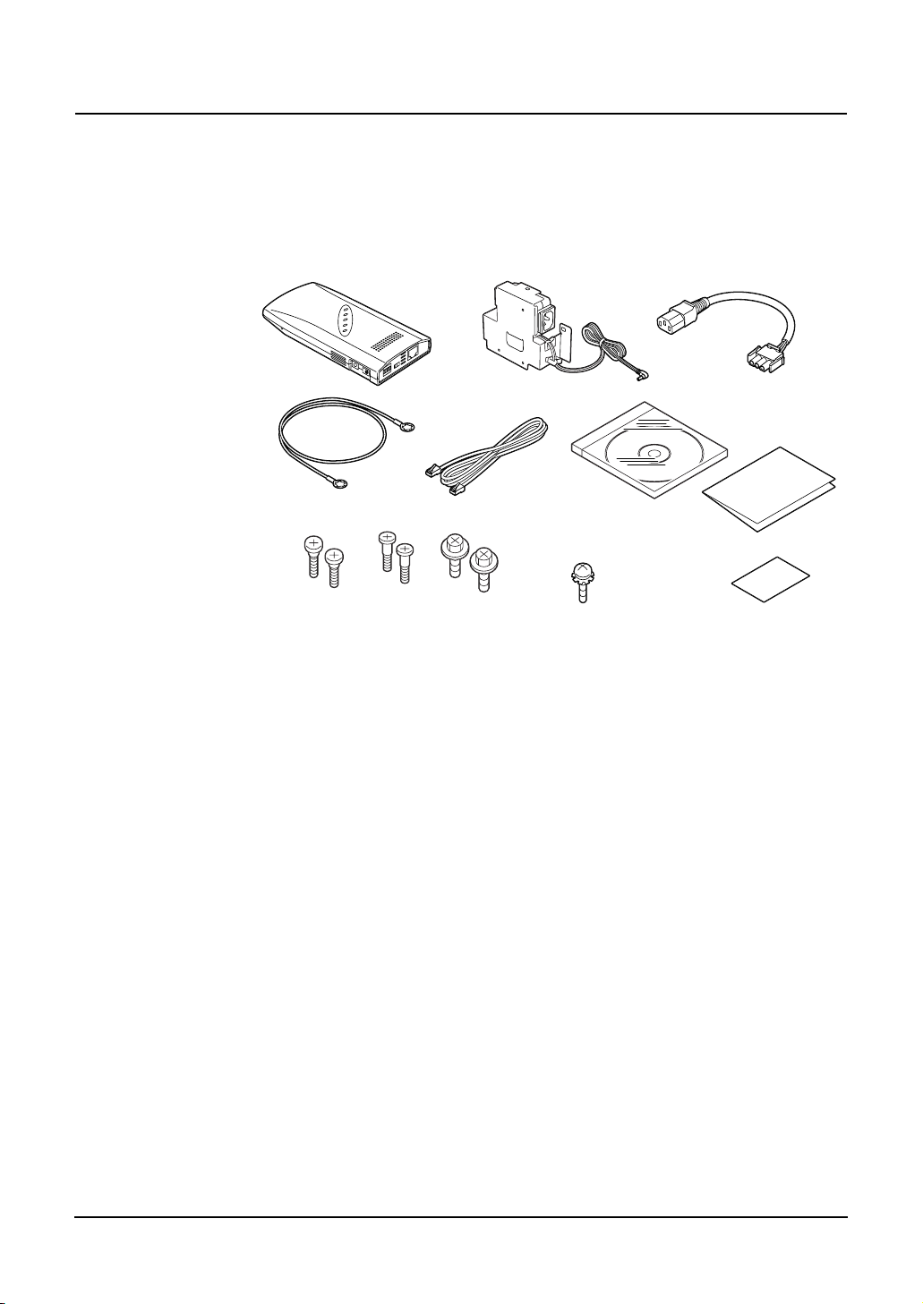
Product Configuration
The configuration of this product is shown below.
Check the contents to make sure that you have everything listed below. If you do not
have all the items, contact your TOSHIBA authorized dealer or service engineer.
• GN-1010 • AC Adapter
• Earth Cable
• Securing Screw
• LAN Cross Cable
Configuration List
GN-1010.................................... 1 pc.
•
AC Adapter (1.8m) ....................1 pc.
•
Power Cable (0.3m) ..................1 pc.
•
LAN Cross Cable (0.75m)......... 1 pc.
•
Earth Cable (0.44m).................. 1 pc.
•
Securing Screw.........................2 pcs. / 2 pcs. / 2 pcs.
•
(Used to secure the GN-1010 on the Multifunctional Digital System. / Used to secure the recommended hub on the Multifunctional Digital
System.
/ Used to secure the AC adapter bracket.)
Earth Cable Securing Screw..... 1 pc.
•
(Used to secure the earth cable on the GN-
1010.)
CD-ROM ...................................1 pc.
•
(Contains the utility software and the .pdf version of this manual.)
Installation Manual ....................1 pc.
•
(Explains the unpacking and installation procedures.)
Approval Label ..........................1 pc.
•
(Affixes the approval label to the body, which is
applied to each country.)
• Power Cable
• CD-ROM
• Earth Cable Securing
Screw
• Installation Manual
• Approval Label
8 GN-1010 User’s Manual — Before Using Product
Page 10

Adobe Acrobat Reader is required to view or print the manual contained in this CD-
•
ROM.
Adobe Acrobat Reader may be downloaded as free software from the home page of
Adobe Systems Incorporated. (www.adobe.com)
INTRODUCTION
Thank you for purchasing the GN-1010 Wireless LAN Adapter.
This product is a wireless LAN adapter using the 2.4 GHz spectrum diffusion system,
and is compatible with IEEE Standard 802.11b for wireless LAN.
The GN-1010 is designed for use as an access point, as well as a station (Ethernet ↔
wireless converter).
It is independent from operating systems or protocols, meaning it can be connected by
LAN cable to any Ethernet-compatible Multifunctional Digital System for immediate
wireless LAN use.
* This manual explains how to use the GN-1010.
* Be sure to read it carefully, so you can use the product correctly.
Features
It can be installed on the Multifunctional Digital System for space saving.
•
Operates as an access point or a LAN station.
•
Uses compact, lightweight AC adapter.
•
Full range of functions (roaming, 11-channel support).
•
Automatic transmission speed (wireless) switching.
•
Automatically switches transmission speeds from 11Mbps to 5.5Mbps, 2Mbps,
1Mbps according to conditions.
The following terms and abbreviations are used in this manual for convenience.
•
GN-1010 ..........................................................Adapter
GN-1010 or a device containing the above .....Wireless terminal, User unit
Personal computer...........................................PC
Access point ....................................................AP
Station..............................................................ST
GN-1010 User’s Manual — Introduction 9
Page 11

TABLE OF CONTENTS
HANDLING PRECAUTIONS ....................................................................................1
PRECAUTIONS FOR USE.......................................................................................1
ABOUT TOSHIBA WIRELESS SOLUTION .............................................................1
Wireless LAN Adapter Types ............................................................................ 1
Wireless LAN Adapters ..................................................................................... 2
Wireless Interoperability ....................................................................................2
Wireless LAN and your Health .......................................................................... 2
Safety Instruction for Wireless Products............................................................2
Limitation of Liability ...................................................................................3
Usage Restrictions ..................................................................................... 3
WARNING .................................................................................................. 4
NOTE.......................................................................................................... 4
Regulatory Information ......................................................................................5
Canada - Industry Canada (IC) .........................................................................5
Europe - EU Declaration of Conformity ............................................................. 5
USA-Federal Communications Commission (FCC)...........................................6
PRECAUTIONS RELATED TO SERVICE ...............................................................7
NOTES! ....................................................................................................................7
BEFORE USING PRODUCT ...................................................................................8
Product Configuration........................................................................................8
Configuration List........................................................................................8
INTRODUCTION ...................................................................................................... 9
Features ............................................................................................................9
TABLE OF CONTENTS.......................................................................................... 10
OVERVIEW ............................................................................................................12
Component Locations...................................................................................... 12
LED Indicators.......................................................................................... 13
DIP Switches ............................................................................................14
Multi-channel Operations................................................................................. 15
OPERATING MODE............................................................................................... 16
Infrastructure (Wi-Fi Mode)..............................................................................16
Station (ST) ..............................................................................................16
Access Point (AP).....................................................................................16
USING THE UTILITY SOFTWARE ........................................................................ 18
Connecting between the GN-1010 and PC .....................................................18
Connection with Cross Cable ................................................................... 18
Connection with Hub ................................................................................18
Preparing the Utility Software .......................................................................... 19
Node Registration............................................................................................20
Configuration ...................................................................................................22
10 GN-1010 User’s Manual — Table of Contents
Page 12

FUNCTIONS OF THE UTILITY SOFTWARE .........................................................24
Main Menu Screen ..........................................................................................24
Node Registration............................................................................................25
Configuration ...................................................................................................26
Configuration Screen................................................................................ 26
Base ......................................................................................................... 27
Wireless....................................................................................................29
Filter.......................................................................................................... 33
SNMP ....................................................................................................... 42
Spanning Tree..........................................................................................42
File Management.............................................................................................43
Status .............................................................................................................. 44
Common Items .........................................................................................44
Environment .............................................................................................45
Interfaces..................................................................................................46
Wireless Node ..........................................................................................48
Bridge ....................................................................................................... 49
Spanning Tree..........................................................................................50
Wireless Counter......................................................................................51
TROUBLESHOOTING............................................................................................52
When Communications Fails........................................................................... 52
Check Software ........................................................................................52
Check Peripheral Environment or Installation Location............................ 52
When Device Cannot Be Detected Automatically By Node Registration ........ 53
When Device Does Not Start........................................................................... 53
Check Power LED ....................................................................................53
APPENDIX..............................................................................................................54
Product Specifications .....................................................................................54
External Dimensions.................................................................................54
Physical Specifications.............................................................................54
Software Specification .............................................................................. 55
Installation Environment Conditions (Environment Specifications) ..........55
Input/Output Interface...............................................................................55
Glossary .......................................................................................................... 56
GN-1010 User’s Manual — Table of Contents 11
Page 13
OVERVIEW
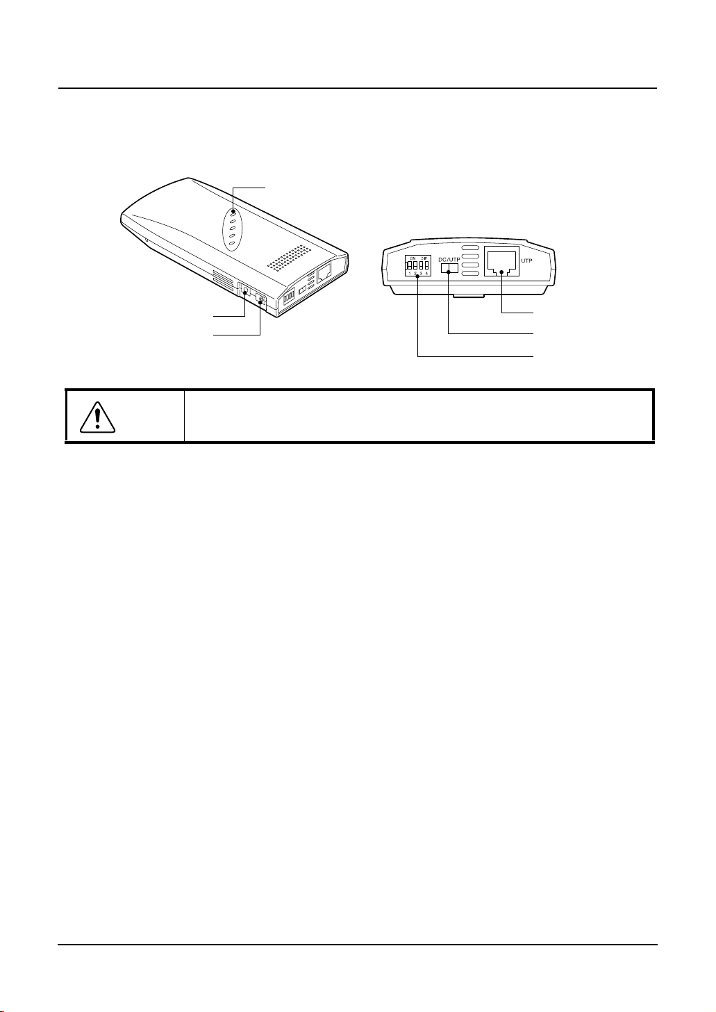
Component Locations
LED
Ground Terminal
Power Supply Plug
Do not obstruct the ventilation slots.
Caution
This can cause heat buildup, which can lead to damage or failure.
•
•
•
•
UTP Connector
Power Supply Switch
DIP Switches
LED
The five LED indicators indicate the sending /receiving status of the wireless or
wired LAN, power supply, LAN connection status, etc.
DIP Switches
The DIP switches are used for initialization and operating mode selection.
Power Supply Switch
Always select power supply from the AC adapter (“DC” side).
UTP Connector
The UTP connector is used to connect the LAN cable.
12 GN-1010 User’s Manual — Overview
Page 14

LED Indicators
The five LED indicators indicate the sending /receiving status of the wireless or wired
LAN, power supply, LAN connection status, etc. as follows.
Name Status Description
POWER Flashing Startup, or startup error
Illuminates Operating
Flashing 2 times Initializing error
Flashing 3 times Firmware writing error
WLINK Illuminates Wireless LAN is connected normally.
WRX Flashing Receiving wireless LAN data
LINK Illuminates Wired LAN is connected normally.
RX Flashing Receiving wired LAN data
POWER
WLINK
WRX
All flashing simultaneously
Firmware writing in progress
GN-1010 User’s Manual — Overview 13
Page 15
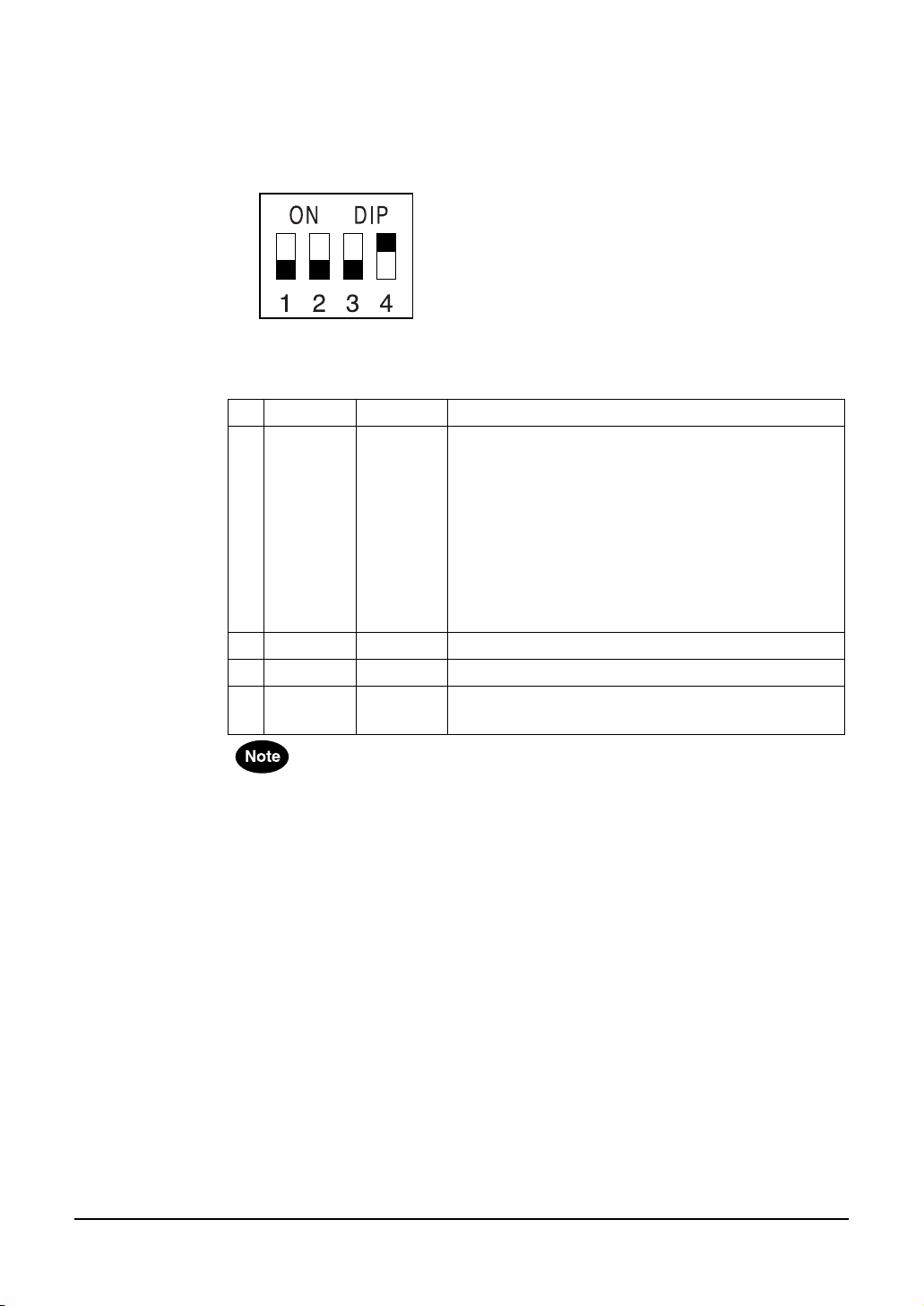
DIP Switches
The DIP switches are used to make device settings.
— DIP Switch Default Setting (Factory Setting)
* Default Setting: 1to 3=OFF / 4=ON
— Function of DIP Switch
No. ON OFF Description
1 INIT < - > Used to initialize the GN-1010.
2 - - This switch is always at “OFF”.
3 - - This switch is not used.
4 <INFRA> - This switch is always at “ON”.
The default setting for this device gives priority to the utility software.
•
The GN-1010 operates as a station in default.
•
When the device connection is completed, the GN-1010 can operate as a station.
Launch the utility software, then set the same ESS ID as that of the access point.
When the WEP function is used, the WEP key setting is also required.
1. Turn the power of the GN-1010 ON.
2. LED indicators (POWER, WLNK, WRX) begin to
flash.
3. While they are flashing (approx. 3 seconds), turn
the DIP switch 1 OFF.
Before restarting or turning the power off, wait until
•
the LED indicators (POWER, WLNK, WRX) stop
flashing and the GN-1010 returns to the status prior
to initializing.
Used in the infrastructure (Wi-Fi mode).
•
14 GN-1010 User’s Manual — Overview
Page 16
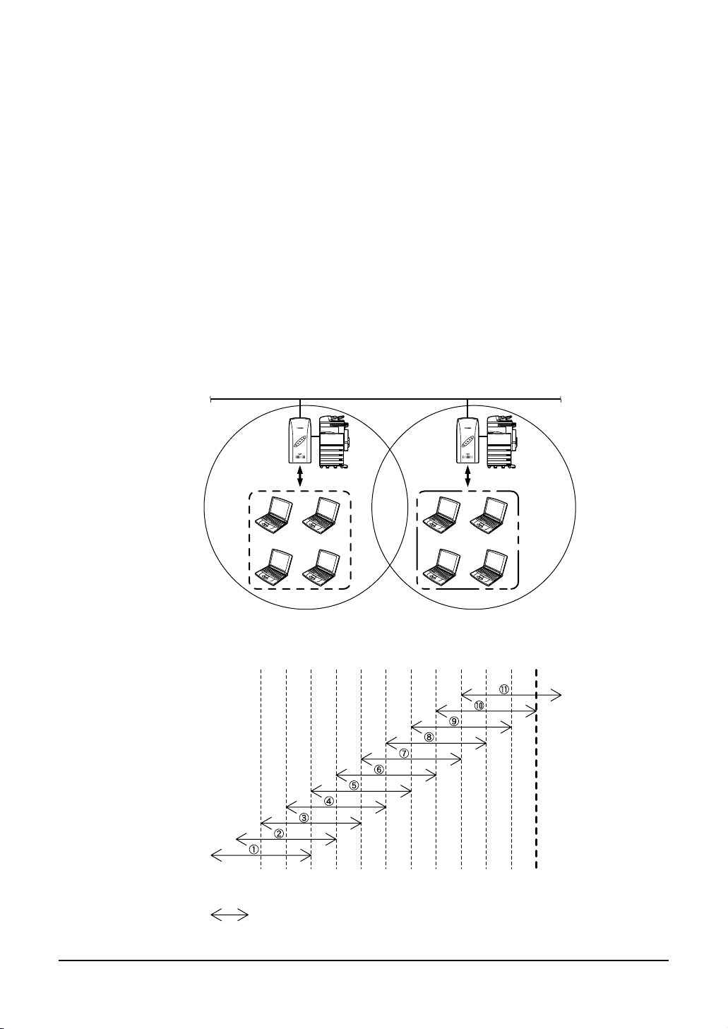
Multi-channel Operation
By changing channels on adjacent access points, it is possible to obtain higher throughput per wireless terminal, than when channels are not changed, even when the number
of wireless terminals are increased.
The 2.4G ISM band (2400 to 2472 MHz) in which this product operates is subdivided
into 11 channels, numbered 1 to 11, by IEEE standard 802.11, because each frequency
has sidebands around its central frequency, sidebands on adjacent channels overlap.
Overlapping frequencies can adversely affect communications by interference with
each other's transmissions.
Refer to the figure below when selecting channels, to ensure the frequency bands
•
do not overlap.
The maximum number of channels which can be used simultaneously without inter-
•
ference is three. By using a combination of channels 1, 6, 11. Channel numbers
can be set from 1 to 11 using utility software.
Channel numbers can be set from 1 to 11 using the utility software.
•
Even on the same network, the wireless terminals which have different channels
cannot communicate with each other.
Network
AP1
Channel 1
2412 2417 2422 2427 2432 2437 2442 2447 2452 2457 2462 2467 2472
1234567891011
AP2
Channel 6
Center Frequency
(MHz)
Channel
: Sideband frequency range for each channel
GN-1010 User’s Manual — Overview 15
Page 17
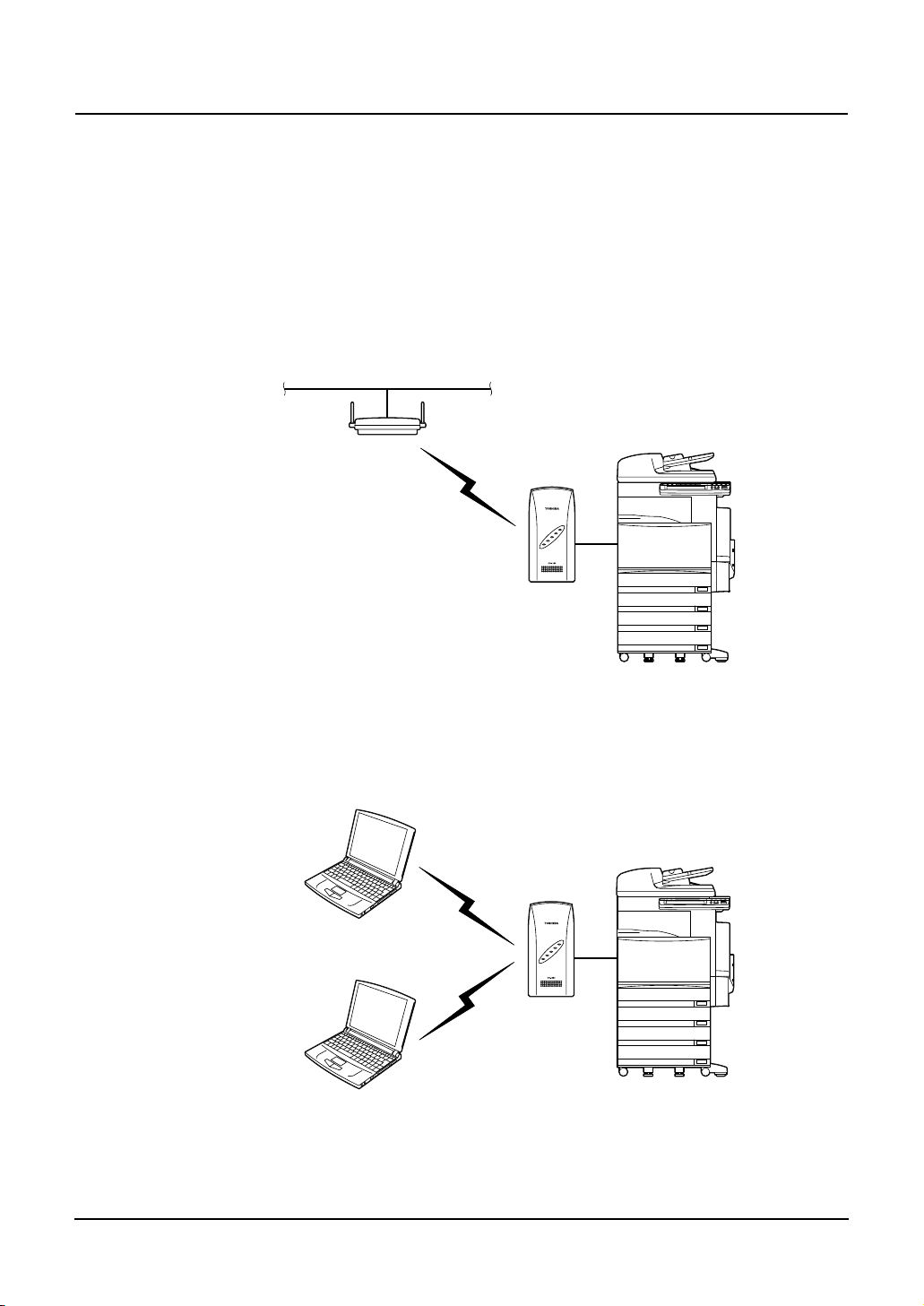
OPERATING MODE
Infrastructure (Wi-Fi Mode)
Station (ST)
When connecting to another access point, the GN-1010 can communicate with as a
station.
The GN-1010 can be connected to the network via the access point.
Access Point (AP)
The GN-1010 operates as an access point, and can receive communication from
another wireless terminal.
16 GN-1010 User’s Manual — Operating Mode
Page 18
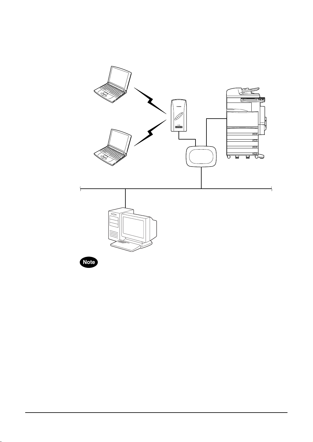
— Using the GN-1010 as an access point on the existing
LAN environment
The wireless LAN environment can be newly added to the existing LAN environment.
The GN-1010 can communicate with a wireless client and a wired client.
Hub
Purchase the hub (recommended model) separately.
•
Use a straight cable which connects between the hub and the GN-1010.
•
The straight cable is not included with this product.
The recommended hub can be directly attached to the Multifunctional Digital Sys-
•
tem.
For details, contact your TOSHIBA authorized dealer or service engineer.
In the infrastructure (Wi-Fi mode), all the wireless terminals perform communica-
•
tions via the access point.
Since the roaming function is supported, log-in to any access point where the radio
waves are accessible.
GN-1010 User’s Manual — Operating Mode 17
Page 19
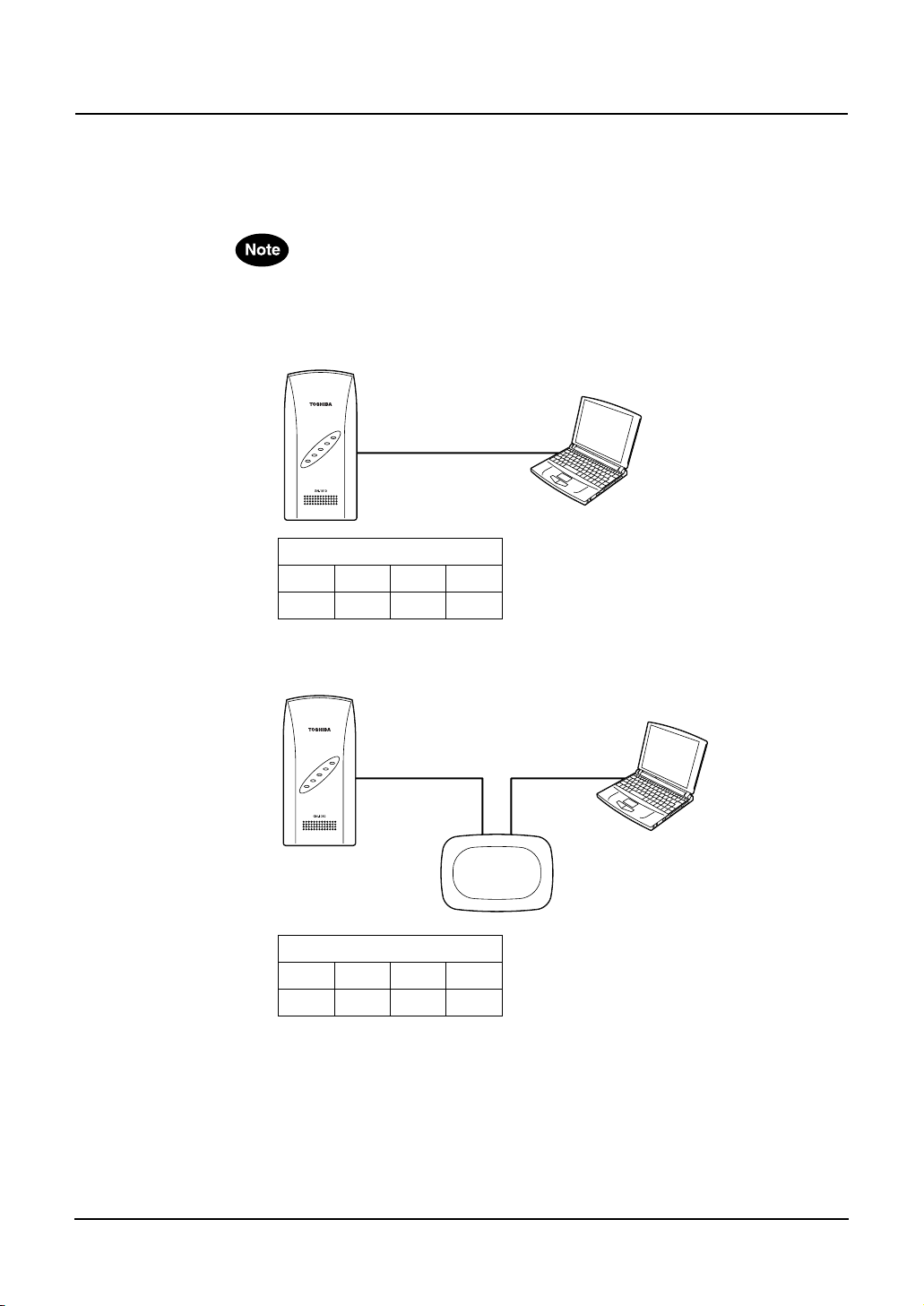
USING THE UTILITY SOFTWARE
Connecting between the GN-1010 and PC
To set the GN-1010 using the utility software, one Windows PC is required.
Ensure that the DIP switch 2 is “OFF”.
•
Connection with Cross Cable
Attached Cross Cable
DIP Switch
1234
OFF OFF OFF ON
Connection with Hub
Straight Cable
Hub
DIP Switch
1234
OFF OFF OFF ON
18 GN-1010 User’s Manual — Using the Utility Software
Page 20

Preparing the Utility Software
1.
Insert the CD-ROM in the CD-ROM drive of the computer.
2. Use Windows Explorer to copy the file "APUTIL.EXE"
in the "Utility" holder from the CD-ROM to the appropriate directory.
• Example: C:
3.
Double click the APUTIL.EXE file to open the Access
Point Maintenance Utility.
4.
You will see the following main menu.
\
WLANUTIL\
GN-1010 User’s Manual — Using the Utility Software 19
Page 21

Node Registration
The first time you use the GN-1010, you must perform the “Node Registration”, which
automatically detects and registers the GN-1010.
Once the “Node Registration” detects the GN-1010 installed on the network, its information will be stored in a file. Therefore, it is not required to perform “Node Registration”
each time you start the utility.
1. Launch the utility software.
2.
Click [Node Registration] from the main menu.
3. Click [Search] to detect an access point.
MAC address and IP address for each access point detected are dis-
•
played in the Access Point List.
4. From the list, double-click an access point of which
the name is registered.
When an access point cannot be detected, close the utility software. Then, launch it
•
again to detect it.
Furthermore, if the access point cannot be detected after repeating the steps above,
see the section "Troubleshooting" (P.52).
20 GN-1010 User’s Manual — Using the Utility Software
Page 22

5.
Enter the access point name and click [OK].
Up to 32 characters are allowed. Also, a maximum of 1024 devices
•
can be registered.
6.
Click [Exit] to complete the detection.
• Program returns to the main menu.
GN-1010 User’s Manual — Using the Utility Software 21
Page 23

Configuration
The utility software allows you to set the GN-1010. This section explains the basic
operation flow for configuration.
For the detailed information on setting parameters, see the section "Functions of the
Utility Software" (P.24).
Parameters in the configuration dialog box displayed when you click [Configuration] in
step 2 are those for the utility software default setting. Therefore, you must register
an appropriate name for this device to the "Name" field as described in the preceding
section "Node Registration" and click [Read] to load the current setting before performing the setting operation.
1.
2. Click [Configuration] from the main menu.
Launch the utility software.
3. Click the Access Point drop-down list and select the
access point you want to set or edit.
22 GN-1010 User’s Manual — Using the Utility Software
Page 24

4.
Click [Read] to load the setting of the device.
5. Click [OK].
When the password has been set for the selected device, enter it and
•
click [OK].
6. Click the appropriate tab and edit the parameters.
For detailed information of the configuration menu, refer to the section
•
"Configuration" (P.26).
7. After the setting is completed, click [Write].
8. Click [Reboot] to restart the GN-1010.
After restarting the GN-1010, the setting becomes effective.
•
Click [Read] to check whether the setting becomes effective.
•
GN-1010 User’s Manual — Using the Utility Software 23
Page 25

FUNCTIONS OF THE UTILITY SOFTWARE
This section explains each function of the utility software.
Main Menu Screen
Button Description
Node
Registration
Configuration Configures a device selected in the Access Point drop-down list.
File
Management
Status Displays information of the selected device.
Exit Exits the program.
Registers data for the devices on the network.
This function can detect a device on the network, and add or edit the
device information. To maintain a device, its information must be
registered.
This funciton can read and write the configuration information of the
selected device. Also, it can save the current configuration information as a text-format file, and load the saved file.
Manages configuration file and firmware.
This function can update the firmware version for the selected
device. Also, it can read and write the configuration information.
The information is treated as a text-format file.
This function diplays information such as device operating environment and sending/receiving counters.
24 GN-1010 User’s Manual — Functions of the Utility Software
Page 26

Node Registration
This function registers information of which devices exist on the network.
Since the maintenance operation such as parameter setting and firmware upgrading is
performed on the basis of information entered here, you must register the appropriate
information.
Button Description
Search This function automatically detects and registers all devices con-
nected to the same network group.
If you want to manage devices located on the far side of an IP router,
click [New] to register each device directly.
Clear Deletes all registered data.
New Registers data for a new device to be managed.
Delete Deletes data of the device selected in the Access Point List.
Exit Returns to the main menu.
Assigning names to the devices found by the automatic search makes it easier to
•
identify the devices on the network.
Up to 32 characters are allowed for each name. A maximum of 1024 devices can
be registered.
To modify the data displayed in the Access Point List, double-click the access point
•
you want to modify to open the edit window.
You can also use the "File Management" menu to save the current Access Point List
•
data on the hard disk or load a previously saved file.
GN-1010 User’s Manual — Functions of the Utility Software 25
Page 27

Configuration
This function sets the basic parameters such as the operating mode as well as the wireless parameters.
Configuration Screen
1
2
3
1. Access Point....................Selects the desired access point.
2. Configuration Tab ............Configuration menus are organized into each tab.
3. [Password].......................Changes the password for the selected device.
4. [Read]..............................Reads the configuration for the selected device.
5. [Write] ..............................Writes the currently displayed configuration to the selected
6. [Default] ...........................Restores the factory default setting.
7. [Reboot]...........................Reboots the selected device.
8. [Exit] ................................Returns to the main menu.
45
• “SNMP” and “Spanning Tree” tabs are not used.
• Up to 6 alphanumerics can be entered and is case-sensitive.
• To change the password, enter the current password
and new one.
• To make the new password effective, the reboot operation is required.
device.
• To make the configuration effective, the reboot operation
is required.
• To apply the setting, write the configuration to the device
and reboot it.
6
7
8
Password enrty is required for [Password], [Read], [Write], [Reboot] commands.
•
The factory default setting has no password. In this case, you need not enter anything.
Executing the command “[File] - [Save]” can save the currently displayed configura-
•
tion on the hard disk and “[File] - [Open]” can load a previously saved file.
26 GN-1010 User’s Manual — Functions of the Utility Software
Page 28

<Entry Item>
Classifi-
cation
IP
Parame-
ters
Wireless
Parame-
ters
Base
This tab sets the IP parameters, wireless parameters and other basic operating settings
for the device.
Parameter Default
Value
IP Address
(*2)
Subnet
Mask
(*2)
Default
Gateway
(*2)
Enable DIP
Switch
Network
Mode
Unit Type Station Determines the unit type.
10.xxx.xxx.x
xx
(*1)
255.0.0.0 Enters the subnet mask assigned by the network adminis-
0.0.0.0 Enters the IP address of the default gateway.
Disabled Determines whether or not the DIP switch is used.
Infrastruc-
ture
(Wi-Fi
Mode)
Enters the IP address assigned by the network administrator.
trator.
Enabled/Disabled
•
Selects the wireless operating mode.
ADHOC (Simple Mode)
•
Infrastructure (Standard Mode)
•
Infrastructure (Wi-Fi Mode)
•
Infrastructure (Advanced Mode)
•
The GN-1010 supports "Infrastructure (Wi-Fi Mode)" only.
*
Effective only when "Infrastructure" is selected in "Net-
*
work Mode".
Station : Operates as a station (wireless
•
Access Point : Operates as an access point.
•
Description
terminal).
GN-1010 User’s Manual — Functions of the Utility Software 27
Page 29

Classifi-
cation
Wireless
Parame-
ters
Parameter Default
Val ue
Channel Setting is
not allowed.
(10)
ESS ID LocalGroup Enters the name of wireless LAN network on which the
ANY ID
Blocking
Transmit
Rate
Age Time 5 min. Selects time (minutes) to keep the wireless device informa-
Static Node
Address
Disabled Determines whether or not the log-in from a station which
Auto (All) Selects transmit speed of the wireless transmission side.
Setting is
not allowed.
Selects the number of wireless channels. The channels of
12 to 14 cannot be used even if selected.
1 to 11
•
Setting method differs depending on "Extented Roaming"
*
setting.
Extended
Roaming
Disabled Auto One channel only
Enabled Multi-channel
device belongs.
Up to 32 alphanumerics (case-sensitive)
•
Communication between the wireless devices with
*
different names is not possible.
Network can be split by changing the name.
has no ESS ID is refused.
Enabled/Disabled
•
When "Enable" is set, the log-in from a device which has
*
no ESS ID will be refused.
1Mb/s
•
2Mb/s
•
Auto (1Mb/s, 2Mb/s)
•
5.5Mb/s
•
11M b/s
•
Auto (All)
•
tion (for AP only) and the MAC address information of the
bridge, which are internally managed.
3 to 65535
•
If no communication occurs within the time set here, the
*
information will be deleted.
Sets the MAC address of PC connected to Ethernet side.
(For a station of “Infrastructure (Wi-Fi Mode)“)
Without MAC Address Designation
•
With MAC Address Designation
•
If the MAC address is not designated, it will be automati-
*
cally obtained from the communication data on Ethernet.
Description
Station Access Point
One channel only
is allowed.
(*1) : Factory default setting for IP address
Unique value is set by using the lower 3 bytes in 6 bytes of Ethernet address.
Ex.: Ethernet Address IP Address
00-80-4C-01-02-03
00-80-4C-0D-0E-0F
The first portion “10” is the same.
(*2) : When you use only the GN-1010 as a wireless device, the setting is not
required. However, when using the GN-1010 together with other wireless
devices or using it on the far side of an IP router, you must set these items.
→ 10.1.2.3
→ 10.13.14.15
28 GN-1010 User’s Manual — Functions of the Utility Software
Page 30

<Entry Item>
Classifi-
cation
WSL
(Original)
WEP
Exten-
sion
Control
Wireless
This tab sets the wireless parameters for the device.
Parameter Default
Value
WSL Scram-
ble
WSL Scram-
ble Key
WEP Disabled Determines whether or not the WEP funciton is used.
Default Tx
Key
Key 1 Setting is
Key 2 to 4 Disabled
Extended
Roaming
(*1)
Roaming
Threshold
(*2)
RSSI Sam-
pling
Time (*2)
Disabled
0 to all
Setting is
not allowed.
(1)
not allowed.
(A1B2C3D4
E5
40 bits)
Disabled Sets the AP roaming method.
Setting is
not allowed.
(80)
Setting is
not allowed.
(3 sec.)
This function is not supported.
Selects the WEP key number to use for data transmission.
1 to 4
•
Sets the WEP key for WEP encryption.
Hexadecimal value (0 to 9, A to F)
•
To perform communications using the WEP function, the
*
key placed in the default send key number used for transmission must be the same as that placed in the same
location on the receiver.
Enabled/Disabled
•
When enabled, "AP Login Priority" setting is allowed.
*
Selects the threshold value to initiate roaming.
50 to 150
•
Roaming is performed when the average RSSI value dur-
*
ing the RSSI sampling time is less than this value.
Selects the sampling time (sec.) to obtain the RSSI value to
initiate roaming.
1 to 10
•
Description
GN-1010 User’s Manual — Functions of the Utility Software 29
Page 31

Classifi-
cation
Exten-
sion
Control
Parameter Default
Value
Extension
Speed
Control
Border of
11M and
5.5M
Border of
5.5M and
2M
Border of
2M and 1M
AP Login
Priority
(*2)
Login Other
AP
(*2)
Disabled When “Extended Roaming“ is enabled, the setting is
Setting is
not allowed.
(90)
Setting is
not allowed.
(80)
Setting is
not allowed.
(70)
Setting is
not allowed.
(no registra-
tion)
Setting is
not allowed.
(Login)
Description
allowed.
Enabled/Disabled
•
Sets the RSSI value as the threshold value, which is applied
when the extension speed is changed from 11 Mbps to 5.5
Mbps, or vice versa in “Extension Speed Control”.
When “Extension Speed Control” is enabled, the setting is
allowed.
Sets the RSSI value as the threshold value, which is applied
when the extension speed is changed from 5.5 Mbps to 2
Mbps, or vice versa in “Extension Speed Control”.
When “Extension Speed Control” is enabled, the setting is
allowed.
Sets the RSSI value as the threshold value, which is applied
when the extension speed is changed from 2 Mbps to 1
Mbps, or vice versa in “Extension Speed Control”.
When “Extension Speed Control” is enabled, the setting is
allowed.
Sets the preferred APs to login.
Up to 5 APs can be registered. APs in smaller numbered
*
positions have higher priority.
Determines whether or not the log-in operation is permitted
to non-registered APs.
(*1) : Applied only to “station”.
(*2) : Allowed when “Extended Roaming” is enabled.
30 GN-1010 User’s Manual — Functions of the Utility Software
Page 32

— Extended Roaming
When using the GN-1010 as a station, you can use “Extended Roaming“ function.
Extended roaming is the function which enhances the normal roaming. This allows
you to specify the roaming threshold and the preferred APs to login.
RSSI 80 Border of AP1
AP1
1
ST ST
Transit
2
AP2
Transit
3
4
Transit
ST
RSSI 80 Border of AP2
ST
When Extented Roaming is enabled and Roaming Threshold is set to 80
• When ST transfers from 1 to 2, ST can connect with AP1 using the connection of
AP1 and RSSI 80.
• When ST transfers from 2 to 3, the connection of AP1 and RSSI 80 cannot be
used. Therefore, log-out is performed from AP1, then the roaming is performed
to AP2 to login.
• When ST transfers from 3 to 4, the connection of AP2 and RSSI 80 cannot be
used. Therefore, log-out is performed from AP2, however in this case, the wireless connection is disconnected because of lack of AP which is allowed to login.
Roaming is performed after the transfer, the following occurs if there are two or
more APs which are allowed to login.
• When “AP Login Priority“ is not specified, log-in will be performed to the AP
which has a higher RSSI value.
• When “AP Login Priority“ is specified, log-in will be performed to the AP which
has a higher priority.
Also, when “Login Other AP“ is disabled, log-in will be allowed to only the preferred
APs registered, even when there are other APs which are allowed to login.
GN-1010 User’s Manual — Functions of the Utility Software 31
Page 33

— Extension Speed Control
“Extension Speed Control” is the function which automatically changes the transmission speed according to the RSSI value.
This lowers the speed when the RSSI value becomes low, and heighten the speed
when the RSSI value becomes high.
When using the GN-1010 as a station, you can use this function.
RSSI 70
RSSI 80
RSSI 90
11Mbps 5.5Mbps 2Mbps 1Mbps
ST
Transit
Transit
AP
1 2 3 4
• There is a station logged in to AP at 1, with the transmission speed 11Mbps.
RSSI value is retained at 90 or more.
• When the station transfers to 2 (RSSI 90 or below and RSSI 80 or more),
“Extension Speed Control“ function will be activated and the transmission speed
will be changed to 5.5Mbps.
• When it transfers to 3 or 4, the speed will be changed to 2Mbps or 1Mbps
respectively.
Transit
32 GN-1010 User’s Manual — Functions of the Utility Software
Page 34

<Display Item>
Classifi-
cation
MAC
Address
Filter
Protocol
Filter
Parameter Default
Enable MAC
Address Fil-
Address List
Enable Pro-
Protocol List - Displays the permitted protocol list when “Protocol Filter“ is
Filter
This tab performs the filter setting regarding MAC address and protocol.
Operation
Button
<Operation Button>
[New].................. Creates new list.
[Delete]............... Deletes the list previously set.
[Open] ................ Opens the saved list file.
[Save]................. Saves created list.
Description
Value
Disabled Determines whether or not the MAC address filter is used.
Enabled/Disabled
•
ter (*1)
MAC
(*1)
tocol
Filter
- Displays the permitted MAC address list when “MAC
Disabled Determines whether or not the protocol filter is used.
When enabled, connection to another AP other than the
*
clients which has the permitted MAC address is refused.
Address Filter“ is enabled. You can register or delete MAC
address, one by one, by [New] or [Delete] command. You
can also load the batch list from the list file, and save a list
as the list file. Up to 1024 addresses can be registered.
Enabled/Disabled
•
When enabled, transmission of the packet other than pro-
*
tocol is refused.
enabled. You can register or delete protocol, one by one, by
[New] or [Delete] command. You can also load the batch list
from the list file, and save a list as the list file. Up to 256
protocols can be registered.
(*1) : Applied only to “access point”.
GN-1010 User’s Manual — Functions of the Utility Software 33
Page 35

— MAC Address Filter
"MAC Address Filter" is the function to permit only user units which have MAC
addresses registered in APs to login. This can refuse log-in to APs to unknown user
units which have not registered.
When MAC addresses of UU1 and UU2 are registered in the MAC address filter list
and the address of UU3 is not, UU1 and UU2 can login to AP, however UU3 cannot
login. To permit UU3 to login to AP, the AP administrator must add MAC address of
UU3 to the MAC address filter list.
MAC Filter List
UU1
UU2
AP
UU1
UU2
UU3
34 GN-1010 User’s Manual — Functions of the Utility Software
Page 36

— MAC Address Filter List File
Reading the list file previously prepared allows you to register MAC addresses in
“MAC Address List“ in one operation.
<Regarding MAC Address Filter List File>
File Name
•
LOGFLIST
Size Specification
•
512byte or below/Line (including space, comment, code regarding line feed)
•
65,536byte (64Kbyte) or below/File (Approx. 1200 lines when each line con-
•
tains 51byte)
Restriction
•
You must enter the line feed command at the end of each line.
•
Addresses registered after the number reaches 1024 are all ignored.
•
Comment
•
Characters following the "#" are considered as comment.
•
When entering comment after the setting contents, you must enter one or
•
more spaces between the contents and "#".
Line Format to specify MAC Address
•
Specified by range
•
NodeAddress=(Start MAC Address),(End MAC Address)
Specified individually
•
NodeAddress=(MAC Address)
<Example of LOGFLIST>
[AP Login Filter Tables] # First Line Not omissible
APLoginFilter=Enabled # Not omissible
(Enabled/Disabled)
NodeAddress=00-80-4C-00-00-00,00-80-4C-FF-FF-FF
#T Company (Specified by range)
NodeAddress=00-80-11-00-00-03 #A Person (Specified individually)
NodeAddress=00-80-21-00-00-04 #B Person (Specified individually)
For entry number, 1 is assinged to the first line of the MAC address specifying lines,
then the next lines 2, 3,... are successively assigned. Note, the entry order of MAC
addresses has no relationship with function.
For the value of "NodeAddress", delimit MAC address with “-” (hyphen) every
2bytes. You can specify multiple MAC addresses by range as well as specify individually. In this case, delimit between the start address and the end address with “,”
(comma). In the example above, all the MAC addresses in 00-80-4C-00-00-00 to
00-80-4C-FF-FF-FF are specified.
GN-1010 User’s Manual — Functions of the Utility Software 35
Page 37

— Protocol Filter
"Protocol Filter" is the function to pass (bridge) only packets of the protocols registered in AP.
This can interrupt traffic of a protocol which is not usually used, and reduce unnecessary use of the wireless bands.
When protocol A is registered in the protocol filter list owned by AP and other protocols such as B are not, packet of protocol A can pass (bridge) through AP, however
packet of protocol B is discarded when passing through AP.
AP
Protocol Filter List
Protocol A
Discard
Protocol A
Protocol B and others
UU
36 GN-1010 User’s Manual — Functions of the Utility Software
Page 38

— Protocol Filter List File
Reading the list file previously prepared allows you to register protocols in “Protocol
List” in one operation.
<Regarding Protocol Filter List File>
File Name
•
PRTFLIST
Size Specification
•
512byte or below/Line (including space, comment, code regarding line feed)
•
65,536byte (64Kbyte) or below/File (Approx. 1200 lines when each line con-
•
tains 51byte)
Restriction
•
You must enter the line feed command at the end of each line.
•
Protocols registered after the number reaches 256 are all ignored.
•
Comment
•
Characters following the "#" are considered as comment.
•
When entering comment after the setting contents, you must enter one or
•
more spaces between the contents and "#".
Line Format to specify Protocol
•
Specified by range
•
ProtocolType=(Ethernet Type),(IP Protocol),
(Start Pot Number),(End Port Number)
Specified individually
•
ProtocolType=(Ethernet Type),(IP Protocol),(Port Number)
Special Format
•
ProtocolType=IP,, ← Permits all the IP protocols
ProtocolType=IP,TCP, ← Permits all the TCP (Port 0 to 65535)
ProtocolType=IP,UDP, ← Permits all the UDP (Port 0 to 65535)
<Example of PRTFLIST>
[Protocol Filter Table] # First Line Not omissible
ProtocolFilter=Enabled # Not omissible (Enabled/Disabled)
ProtocolType=ARP,, Permits #ARP
ProtocolType=IP,ICMP, Permits #ICMP
ProtocolType=IP,UDP,53 Permits #DNS (UDP, Port 53)
ProtocolType=IP,TCP,80 Permits #HTTP (TCP, Port 80)
ProtocolType=IP,TCP,20 Permits #FTP-DATA (TCP, Port 20)
ProtocolType=IP,TCP,21 Permits #FTP (TCP, Port 21)
ProtocolType=IP,TCP,25 Permits #SMTP (TCP, Port 25)
ProtocolType=IP,TCP,110 Permits #POP3 (TCP, Port 110)
ProtocolType=IP,TCP,1352 Permits #Notes (TCP, Port 1352)
For entry number, 1 is assinged to the first line of the protocol specifying lines, then
the next lines 2, 3,... are successively assigned.
GN-1010 User’s Manual — Functions of the Utility Software 37
Page 39

— Registering the MAC Address Filter
1. Check [Enable MAC Address Filter] box.
2. Click [New].
3. Enter address to [Wireless MAC Address 1].
4. When specified by range, check [Range] box and
enter address to [Wireless MAC Address 2].
5.
Click [OK].
38 GN-1010 User’s Manual — Functions of the Utility Software
Page 40

6.
Registered information is displayed on the MAC
Address List.
GN-1010 User’s Manual — Functions of the Utility Software 39
Page 41

— Registering the Protocol Filter
1. Check [Enable Protocol Filter] box.
2. Click [New].
3. Select Ethernet from [Ethernet Type] drop-down list.
4. Set [IP Protocol] and [IP Port Protocol] as required.
5. Click [OK].
40 GN-1010 User’s Manual — Functions of the Utility Software
Page 42

6.
Registered information is displayed on the Protocol
List.
GN-1010 User’s Manual — Functions of the Utility Software 41
Page 43

SNMP
This function is excluded from support.
Spanning Tree
This function is excluded from support.
42 GN-1010 User’s Manual — Functions of the Utility Software
Page 44

File Management
This function is used to obtain the version numbers of the devices connected to the network and to upgrade the firmware or read/write the settings file for the device selected
on the "Access Point List".
If upgrading the firmware is attempted using the files other than specified, performance
will not be guaranteed. Ensure that you use only the specified file.
1
2
3
4
5
6
7
8
1. [Type]...............................Selects setting file.
Firmware/Configuration File/Firmware (Wireless Card)/
MAC Address Filter File/Protocol Filter File
2. [Directory Name] .............Selects file name or directory name.
3. [Get Version]....................Obtains the version information.
• This obtains the verison information from all the devices
connctected to the same network group, or from only the
designated device.
• To obtain data from a device which exists beyond the IP
router, always select the device first. In this case, the IP
parameter must be set correctly.
4. [Read] (*1) ....................... Reads the firmware and setting file, then saves them on
the hard disk.
5. [Write] (*1) ....................... Writes the firmware and setting file saved on the hard disk
to the selected device.
6. [Reboot]...........................Reboots the selected device.
7. [Exit] ................................Returns to the main menu.
8. [Browse] ..........................Browses file name or directory name.
(*1): The file name contains the lower 3 bytes of MAC address of the selected device.
(Ex.) [00-80-4C-4D-20-5E] → [4D205E.TXT]
GN-1010 User’s Manual — Functions of the Utility Software 43
Page 45

Status
This function periodically reads operational data including send and receive counters
from the device specified in "Access Point" and displays it on the screen.
Common Items
1
2
3
1. Access Point....................Selects access point to obtain the status information.
2. Interval............................. Sets the refresh interval to read information. (0 to 120 sec.)
3. Information Tab................Status information items are organized into each tab.
4. [Exit] ................................Returns to the main menu.
5. [Scan Start]......................Periodically reads and diplays information (the refresh
interval is specified in “Interval”).
* When “Interval” is “0”, information is read only once.
6. [Stop] ...............................Stops reading information. (Scan Stop)
7. [Clear]..............................Clears the displayed information.
* You can operate this when scanning is stopped.
* For the items without displaying [Clear], you cannot clear
information corresponding to them.
4
5
6
7
44 GN-1010 User’s Manual — Functions of the Utility Software
Page 46

Environment
This tab displays device information including operating mode, version number, and IP
address.
<Display Item>
Parameter Description
Loader Version Version number of program to execute firmware
Firmware Version Version number of firmware
Firmware Version
(Wireless Card)
Hardware Version Version number of hardware
Ethernet Address Ethernet address assigned to this device
Wireless MAC Address Wireless MAC address assigned to this device
IP Address Current IP address of this device
Subnet Mask Current subnet mask
Default Gateway Current default gateway IP address
Network Mode Current operating mode
Unit Type Current unit type
Channel Number Current wireless channel number
Card Type Wireless card type
Version number of wireless card firmware
GN-1010 User’s Manual — Functions of the Utility Software 45
Page 47

Interfaces
This tab displays data such as send and receive counters for the device's Ethernet and
wireless interfaces.
Interface information can be cleared when scanning is stopped.
•
<Display Item>
Parameter Description
MTU Maximum data size transmitable
Speed Transmission speed of data to be sent
MAC Address MAC address assigned to this interface
Interface State Interface operating state
State Description
up Operating
down Not operating or not linked
Receive Octets Number of bytes received
Receive Packets Number of packets received
Receive Discards Number of packets discarded due to insufficient memory
Receive Errors Number of packets with receive errors
Receive Errors (CRC) Number of packets received with CRC error
If this error occurs frequently on the wireless interface, this
*
may indicate that communication is performed with a device
which has a different encryption setting.
Transmit Octets Number of bytes transmitted
Transmit Packets Number of packets transmitted
46 GN-1010 User’s Manual — Functions of the Utility Software
Page 48

Parameter Description
Transmit Waits Number of packets waiting to be transmitted
Transmit Errors Number of packets with transmit errors
Resets Number of times for which this interface has been reset
GN-1010 User’s Manual — Functions of the Utility Software 47
Page 49

Wireless Node
This tab displays a list of logged-in wireless devices and associated data such as link
quality.
“Wireless Node List” can be cleared when scanning is stopped.
•
<Display Item>
Parameter Description
Login AP (*1) MAC address of currently logged-in AP
Quality (*1) Link quality between this device and logged-in AP
Noise Level (*1) Noise level on station side
Wireless Node List
Wireless MAC
Address
State Login state; applicable when infrastructure mode is set.
Age Time Time to retain device information (sec.)
RSSI Reception level for device (Max. 150)
(*1) Applicable when a device operates as a station.
Unit type: station: Information of logged-in AP
•
Unit type: AP: Infromation of wireless device
•
MAC address of wireless device
It is retained while the device is communicating. When the
*
time reaches "0", it will be deleted.
Higher values indicate higher reception sensitivity.
*
48 GN-1010 User’s Manual — Functions of the Utility Software
Page 50

Bridge
This tab displays the MAC address information managed by this device.
“MAC Address List” can be cleared when scanning is stopped.
•
<Display Item>
Parameter Description
MAC Address MAC addresses of devices connected to the network
Interface Displays the device is on either Ethernet side or wireless
side.
Ethernet/Wireless
•
Age Time Time for which this device information is retained. (minute)
Retained while this device is communicating. When the
*
time reaches "0", it will be deleted.
Wireless MAC
Address
MAC addresses of logged-in wireless devices
Displayed when device is on wireless side.
*
GN-1010 User’s Manual — Functions of the Utility Software 49
Page 51

Spanning Tree
Information of this tab is excluded from support.
50 GN-1010 User’s Manual — Functions of the Utility Software
Page 52

Wireless Counter
This tab displays the number of packets, errors received or transmitted on
wireless communication.
Wireless counter information can be cleared when scanning is stopped.
•
<Display Item>
Parameter Descripiton
TX Unicast Frames Number of packets transmitted by another station using unicast
TX Multicast Frames Number of packets transmitted by another station using multicast
TX Unicast Octets Number of data bytes transmitted by another station using unicast
TX Multicast Octets Number of data bytes transmitted by another station using multi-
TX Deferred Transmissions Number of packets for which the transmission is delayed
TX Single Retry Frames Number of packets retransmitted only once
TX Multiple Retry Frames Number of packets retransmitted multiple times
TX Discards Number of packets discarded
RX Unicast Frames Number of packets received by another station using unicast
RX Multicast Frames Number of packets received by another station using multicast
RX Unicast Octets Number of data bytes received by another station using unicast
RX Multicast Octets Number of data bytes received by another station using multicast
RX FCS Errors Number of packets with FCS (Frame Check Sequence) errors
Rx Discard No Buffer Number of packets with buffer errors
adderss
adderss
adderss
cast adderss
adderss
adderss
adderss
adderss
GN-1010 User’s Manual — Functions of the Utility Software 51
Page 53

TROUBLESHOOTING
This chapter describes common problems which may occur with this product and how
to handle them.
If any problems other than described here occur, check to confirm the re-occurrence.
Then, contact TOSHIBA authorized dealer or service engineer.
When Communication Fails
Check Software
Check if the LAN cables are connected correctly.
•
Check if the DIP switch is set correctly.
•
Check if the terminals which cannot communicate with each other have the
•
same ESS ID. Two terminals with different ESS ID cannot communicate with
each other.
Check if the IP address and subnet settings have been entered.
•
Check if the operating mode setting has been correctly entered.
•
Check whether or not communication is restricted by security functions.
•
Check whether or not the WEP key setting is the same as that of the recipient
•
device.
If the key placed in the default send key number used for transmission is different from that placed in the same location on the recipient device, communication will not be performed.
Check if the channel setting has been correctly entered.
•
Check if the communication speed setting has been correctly entered.
•
Check Peripheral Environment or Installation Location
A nearby source of electromagnetic interference can prevent communication. In
•
general locations (excluding factories) the following may be sources of electromagnetic emissions.
2.4GHz band wireless networks not compatible with IEEE 802.11b.
•
Microwave ovens
•
Security gates
•
Elevator motors
•
Sometimes communication is hindered by attenuation of electric waves. Attenu-
•
ation occurs naturally as distance from the source of transmission increases, but
may also be caused by objects in the path of the transmission. The objects primarily responsible for attenuation are the following.
Concrete walls
•
Metallic surfaces around antennas
•
Most electromagnetic sources other than wireless networks are local and not contin-
•
uous, and therefore by moving the location of the unit and waiting briefly, communication may be possible.
Also, do not place wireless devices too close together. A distance of at least 1m
should be allowed.
Stable transmission at 11Mbps requires an RSSI value of at least 80.
•
The RSSI value can be verified on the Wireless Device Information tab on the Status screen using the utility software.
52 GN-1010 User’s Manual — Troubleshooting
Page 54

When Device Cannnot Be Detected Automatically By Node Registration
When the utility software cannot automatically detect the device, check the following.
Check the connection between the device and PC which executes the utility soft-
•
ware, referring to the section "Connecting between the GN-1010 and PC" (P.18).
Check the DIP switch setting.
•
When the PC which executes the utility software is the DHCP client, exit the soft-
•
ware. When approx. 1 minute has passed, open the software again.
When Device Does Not Start
Check Power LED
Check that the power LED is on.
•
<When extinguished>
Check if the AC adapter is correctly plugged into the power supply con-
•
nector and an outlet.
Check if the power supply switch is in “DC” side.
•
Check whether or not the power LED is flashing.
•
<When flashing>
If the power LED is still flashing more than 10 minutes after the power is
turned on, the problem may be a device firmware failure. Use the utility software to upgrade the firmware version.
GN-1010 User’s Manual — Troubleshooting 53
Page 55

APPENDIX
Product Specifications
External Dimensions
81
17526.5
Physical Specifications
Item Description
Wired LAN
Unit
Wireless LAN
Unit
External Dimensions (mm) 81 (W) x 26.5 (D) x 175 (H)
Ethernet Standard IEEE 802.3
Data Transmission
Speed
Access Method CSMA/CD
Transmission For-
mat
Data Transmission
Speed
Access Method CSMA/CA + ACK (RTS/CTS)
Transmission
Packet
Wireless Category Low-power data transmission system (2400 to
Aerial Power 10mW/MHz or below
Security WEP
Operating Mode Infrastructure/access point settings available
Weight 0.2kg
10Mbps
IEEE 1802.11b standard DS spectrum diffusion
11, 5.5, 2, 1Mbps (fixed/automatic)
IEEE 802.11b frame
2472MHz)
[Unit: mm]
54 GN-1010 User’s Manual — Appendix
Page 56

Software Specification
Item Description
Protocols IP (RFC 791), ICMP (RFC 792), UDP (RFC 768),
ARP (RFC 826), SNMP (RFC 1157), MIB II (RFC 1213)
Installation Environment Conditions (Environment Specifications)
Item Description
Supply Voltage 5.5 to 7.0 VDC (using AC adapter)
Consumption
Current
Operating
Temperature
Operating
Humidity
Airborne dust Not extreme
Corrosive Gas None
Other Do not obstruct ventilation slits.
0.6A (Max.)
0 to 50°C (main unit), 0 to 40°C (AC adapter)
10 to 90% (without condensation)
Leave 5 cm open space in all directions.
Input/Output Interface
UTP Port Pin Assignments
•
Pin No. Signal
1TD+
2TD3RD+
4 Unused (VCC) *1
5 Unused (GND) *1
6RD7 Unused (VCC) *1
8 Unused (GND) *1
*1: When power is supplied from 10BASE-T
12345678
GN-1010 User’s Manual — Appendix 55
Page 57

Glossary
AP (Access Point)
Access points serve as the bridge between wired networks and wireless networks, as
well as providing bridge functions between segments and IP tunnel functions indispensable to the building of versatile, large-scale networks.
CSMA/CA (Carrier Sense Multiple Access with Collision
Avoidance)
CSMA is a method of avoiding collision by which wireless terminals listen before transmitting and do not transmit if they can hear transmissions from other wireless terminals.
CSMA/CA is CSMA plus additional collision avoidance functions.
DS (Direct Sequence)
A type of spectrum diffusion signal using narrow band modulation with phase modulation, in which the diffusion is by means of phase modulation using a broad band diffusion signal (pseudo random strings).
ESS ID (Extended Service Set ID)
In the GN-1010 series, the ESS ID is similar to a name assigned to the wireless LAN
network to which a unit belongs. Communication between wireless terminals which
have different names cannot be performed.
Wireless network can be partitioned by using different ESS ID names.
IEEE (Institute of Electrical Electronics Engineers)
"I-triple-E," involved in a wide range of fields from communications and computer to
medicine and biology, with primary activities related to publishing articles and sponsoring conferences, but also recommending and setting of standards.
The organization sponsoring Committee 802 which is responsible for LAN related matters.
IEEE 802.11/IEEE 802.11b
The wireless LAN standard established by the IEEE.
LAN (Local Area Network)
A network configured from mutual connections between computers within a limited
area.
Also called an "intranet" or "business or regional data communications network."
RSSI (Receive Signal Strength Indication)
A numeric indicator of incoming signal strength.
RTS (Reqest To Send)
In communication via AP, transmission is controlled by CSMA/CA plus RTS. In RTS, a
wireless terminal asks the AP if it is able to transmit, and only transmits after an OK-tosend acknowledgement signal is returned. This serves to avoid unnecessary collisions
when hidden terminals exist because hidden terminals cannot transmit.
Infrastructure
System to integrate wireless LAN with wired LAN
56 GN-1010 User’s Manual — Appendix
Page 58

Spectrum Diffusion Transmission
A method of transmission in which signals that are normally transmitted over a given
limited frequency band undergo narrow band modulation (primary modulation), then
again diffuse modulation (secondary modulation) to intentionally diffuse the signal over
a broad frequency spectrum.
Channel
This term has the same meaning as a television or radio channel. In the 2.400 to
2.472GHz ISM band used by this product, the IEEE 802.11 standard provides for divi-
sion into 11 channels numbered 1 to 11. Even on the same network, wireless devices
operating on different channels cannot communicate with each other.
Bridge
A device for relaying between LAN's. The bridge determines whether to relay data
based on the address of the computer to which the data is being sent. It can be used to
connect networks having different protocols, or when data for broadcast to all computers is received, can send this to all connected networks.
Router
A device for relaying between LAN's. The router determines data addresses by the
combination of a network address assigned to the network and an individual computer
address. Used particularly in medium-scale and larter LAN systems with very large
number of clients, to reduce traffic (congestion) on communication lines.
Roaming
This term has the same meaning as roaming for a portable phone or PHS. The AP is in
the role commonly called the “antenna/base station” for the phone or PHS, and the user
unit is in the role of the phone itself.
GN-1010 User’s Manual — Appendix 57
Page 59

Page 60

Page 61

Page 62

MULTIFUNCTIONAL DIGITAL COLOR SYSTEMS
Operator's Manual for Wireless LAN Adapter
GN-1010
1-1, KANDA NISHIKI-CHO, CHIYODA-KU, TOKYO, 101-8442, JAPAN
2003 TOSHIBA TEC CORPORATION All rights reserved
R03072038200-TTEC
2003-09
 Loading...