

Page 1
SERVICE MANUAL
FACSIMILE
GD-1210/1250/1270/1160/1260
File No. SME060009D0
R060121A4400-TTEC
Ver04_2011-12
Page 2

Trademarks
• The official name of Windows XP is Microsoft Windows XP Operating System.
• The official name of Windows 7 is Microsoft Windows 7 Operating System.
• Microsoft, Windows, Windows NT, Windows Vista and the brand names and product names of other
Microsoft products are trademarks or registered trademarks of Microsoft Corporation in the U.S.
and/or other countries.
• Apple, AppleTalk, Macintosh, and Mac are trademarks of Apple Computer, Inc. in the U.S. and other
countries.
• PostScript is a trademark of Adobe Systems Incorporated.
• NOVELL, NetWare, and NDS are trademarks or registered trademarks of Novell, Inc.
• Molykote is a registered trademark of Dow Corning Corporation.
• Other company names and product names in this manual are the trademarks of their respective
companies.
© 2006 - 2011 TOSHIBA TEC CORPORATION All rights reserved
Under the copyright laws, this manual cannot be reproduced in any form without prior written permission
of TOSHIBA TEC CORPORATION.
11/04
Page 3
GENERAL PRECAUTIONS REGARDING THE SERVICE FOR
GD-1210/1250/1270/1160/1260
The installation and service shall be done by a qualified service
technician.
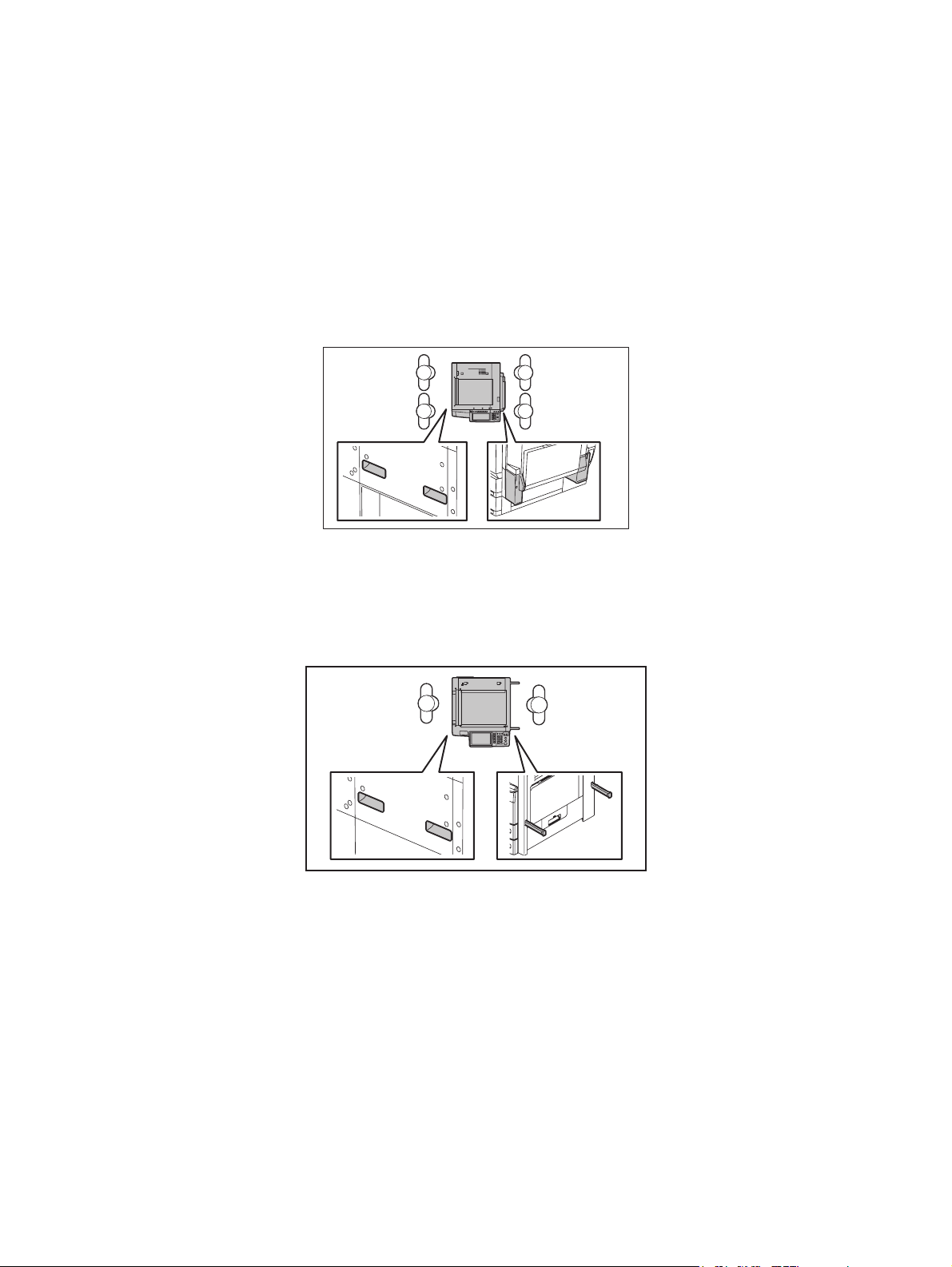
1) Transportation/Installation
- When transporting/installing the equipment, employ four persons and be sure to hold the posi-
tions as shown in the figure.
The equipment is quite heavy and weighs approximately 120 kg (264.55 lb.), therefore pay full
attention when handling it. (e-STUDIO2500c/3500c/3510c, e-STUDIO2330C/2820C/2830C/
3520C/3530C/4520C, e-STUDIO2040C/2540C/3040C/3540C/4540C)
- When transporting/installing the equipment, employ two persons and be sure to hold the posi-
tions as shown in the figure. The equipment is quite heavy, and e-STUDIO205L/255/305 weighs
approximately 57 kg (125.66lb.), and e-STUDIO355/455 weighs approximately 60 kg (132.28
lb.), therefore pay full attention when handling it. The equipment is quite heavy, and eSTUDIO206L/256/306 weighs approximately 58 kg (127.87 lb.), and e-STUDIO356/456 weighs
approximately 61 kg (134.48 lb.), therefore pay full attention when handling it.
- When transporting/installing the equipment, employ four persons and be sure to move it by the
casters while lifting the stoppers. The equipment is quite heavy and weighs approximately 245 kg
(540.12 lb), therefore pay full attention when handling it. (e-STUDIO5520C/6520C/6530C, eSTUDIO5540C/6540C/6550C)
- When transporting/installing the equipment, employ four persons and be sure to move it by the
casters while lifting the stoppers. The equipment is quite heavy and weighs approximately 202 kg
(445.33 lb), therefore pay full attention when handling it. (e-STUDIO555/655/755/855, eSTUDIO556/656/756/856)
- Be sure not to hold the movable parts or units (e.g. the control panel, ADU or RADF) when trans-
porting the equipment.
- Be sure to use a dedicated outlet with AC 110 V / 13.2 A, 115 V or 127 V / 12 A, 220-240 V / 8 A
for its power source.
- The equipment must be grounded for safety.
11/12
Page 4

- Select a suitable place for installation. Avoid excessive heat, high humidity, dust, vibration and
direct sunlight.
- Provide proper ventilation since the equipment emits a slight amount of ozone.
- To insure adequate working space for the copying operation, keep a minimum clearance of 80
cm (32”) on the left, 80 cm (32”) on the right and 10 cm (4”) on the rear.
- The equipment shall be installed near the socket outlet and shall be accessible.
- Be sure to fix and plug in the power cable securely after the installation so that no one trips over
it.
2) General Precautions at Service
- Be sure to turn the power OFF and unplug the power cable during service (except for the service
should be done with the power turned ON).
- Unplug the power cable and clean the area around the prongs of the plug and socket outlet once
a year or more. A fire may occur when dust lies on this area.
- When the parts are disassembled, reassembly is the reverse of disassembly unless otherwise
noted in this manual or other related documents. Be careful not to install small parts such as
screws, washers, pins, E-rings, star washers in the wrong places.
- Basically, the equipment should not be operated with any parts removed or disassembled.
- The PC board must be stored in an anti-electrostatic bag and handled carefully using a wristband
since the ICs on it may be damaged due to static electricity.
Caution: Before using the wristband, unplug the power cable of the equipment and
make sure that there are no charged objects which are not insulated in the
vicinity.
- Avoid expose to laser beam during service. This equipment uses a laser diode. Be sure not to
expose your eyes to the laser beam. Do not insert reflecting parts or tools such as a screwdriver
on the laser beam path. Remove all reflecting metals such as watches, rings, etc. before starting
service.
- Be sure not to touch high-temperature sections such as the exposure lamp, fuser unit, damp
heater and areas around them.
- Be sure not to touch high-voltage sections such as the chargers, transfer belt, 2nd transfer roller,
developer, high-voltage transformer, exposure lamp control inverter, inverter for the LCD backlight and power supply unit. Especially, the board of these components should not be touched
since the electric charge may remain in the capacitors, etc. on them even after the power is
turned OFF.
- Make sure that the equipment will not operate before touching potentially dangerous places (e.g.
rotating/operating sections such as gears, belts pulleys, fans and laser beam exit of the laser
optical unit).
- Be careful when removing the covers since there might be the parts with very sharp edges
underneath.
- When servicing the equipment with the power turned ON, be sure not to touch live sections and
rotating/operating sections. Avoid exposing your eyes to laser beam.
- Use designated jigs and tools.
- Use recommended measuring instruments or equivalents.
- Return the equipment to the original state and check the operation when the service is finished.
- Be very careful to treat the touch panel gently and never hit it. Breaking the surface could cause
malfunctions.
3) Important Service Parts for Safety
- The breaker, door switch, fuse, thermostat, thermofuse, thermistor, IC-RAMs including lithium
batteries, etc. are particularly important for safety. Be sure to handle/install them properly. If
these parts are short-circuited and their functions become ineffective, they may result in fatal
accidents such as burnout. Do not allow a short-circuit or do not use the parts not recommended
by Toshiba TEC Corporation.
4) Cautionary Labels
Page 5

- During servicing, be sure to check the rating plate and cautionary labels such as “Unplug the
power cable during service”, “CAUTION. HOT”, “CAUTION. HIGH VOLTAGE”, “CAUTION.
LASER BEAM”, etc. to see if there is any dirt on their surface and if they are properly stuck to the
equipment.
5) Disposal of the Equipment, Supplies, Packing Materials, Used Batteries and IC-RAMs
- Regarding the recovery and disposal of the equipment, supplies, packing materials, used batter-
ies and IC-RAMs including lithium batteries, follow the relevant local regulations or rules.
6) When the option has been installed:
When the EFI printer board has been installed, be sure to unplug the power cable before performing
maintenance and inspection, otherwise troubles such as a communication error may occur.
Caution:
Dispose of used batteries and IC-RAMs including lithium batteries according to this manual.
Attention:
Se débarrasser de batteries et IC-RAMs usés y compris les batteries en lithium selon ce manuel.
Vorsicht:
Entsorgung der gebrauchten Batterien und IC-RAMs (inclusive der Lithium-Batterie) nach diesem Handbuch.
Page 6

Page 7

CONTENTS
GD-1210/1250/1270/116 0/1260
1. SPECIFICATIONS AND OUTLINE OF SYSTEM ......................................................... 1-1
1.1 FAX Options ........................................................................................................................ 1-1
1.2 Specifications....................................................................................................................... 1-2
1.3 Features .............................................................................................................................. 1-5
1.4 Accessories and Parts......................................................................................................... 1-7
1.5 Options ................................................................................................................................ 1-8
1.6 System List ........................................................................................................................ 1-10
1.6.1 e-STUDIO2500c/3500c/3510c ............................................................................... 1-10
1.6.2 e-STUDIO2330C/2820C/2830C/3520C/3530C/4520C .......................................... 1-11
1.6.3 e-STUDIO5520C/6520C/6530C ............................................................................. 1-12
1.6.4 e-STUDIO205L/255/305/355/455........................................................................... 1-13
1.6.5 e-STUDIO555/655/755/855.................................................................................... 1-14
1.6.6 e-STUDIO2040C/2540C/3040C/3540C/4540C...................................................... 1-15
1.6.7 e-STUDIO5540C/6540C/6550C ............................................................................. 1-16
1.6.8 e-STUDIO556/656/756/856.................................................................................... 1-17
1.6.9 e-STUDIO206L/256/306/356/456........................................................................... 1-18
1.7 Overview............................................................................................................................ 1-19
1.7.1 e-STUDIO2500c/3500c/3510c ............................................................................... 1-19
1.7.2 e-STUDIO2330C/2820C/2830C/3520C/3530C/4520C,
e-STUDIO2040C/2540C/3040C/3540C/4540C...................................................... 1-20
1.7.3 e-STUDIO5520C/6520C/6530C, e-STUDIO5540C/6540C/6550C ........................ 1-21
1.7.4 e-STUDIO205L/255/305/355/455, e-STUDIO206L/256/306/356/456 .................... 1-22
1.7.5 e-STUDIO555/655/755/855, e-STUDIO556/656/756/856 ...................................... 1-23
1.8 Layout of PC Boards..........................................................................................................1-24
2. LSU-RELATED FUNCTIONS .......................................................................................2-1
2.1 Recording Mode .................................................................................................................. 2-1
2.2 Recording Paper Selection Algorithm and Printing Algorithm ............................................. 2-2
2.2.1 Recording paper selection algorithm ........................................................................ 2-2
2.2.2 Printing algorithm ..................................................................................................... 2-2
2.2.3 Setting for the split recording.................................................................................... 2-6
2.3 Recording Paper and Function ............................................................................................ 2-7
2.3.1 Table of the recording paper selection modes ......................................................... 2-8
2.3.2 Others....................................................................................................................... 2-8
2.4 Energy Saver Mode............................................................................................................. 2-9
2.5 Memory Reception.............................................................................................................2-10
3. DIALING/COMMUNICATION CONTROL..................................................................... 3-1
3.1 Circuit Connection and Procedure to Change Mode ........................................................... 3-1
3.1.1 Dial call-up transmission to a telephone circuit ........................................................ 3-1
3.1.2 Selection of the communication mode ..................................................................... 3-2
3.1.3 Procedure to select the transmission mode ............................................................. 3-2
3.2 Signaling System Diagram and Signal Forms ..................................................................... 3-3
3.2.1 Circuit control signals ............................................................................................... 3-3
3.2.2 Communication with the binary signals .................................................................... 3-4
3.2.3 V.8/V.34 communication sequence ........................................................................ 3-13
3.3 FAX Automatic Switching .................................................................................................. 3-26
3.3.1 General functions ................................................................................................... 3-26
3.3.2 TEL mode ............................................................................................................... 3-26
3.3.3 FAX mode .............................................................................................................. 3-26
4. ELECTRICAL CIRCUITS ..............................................................................................4-1
4.1 Configuration ....................................................................................................................... 4-1
© 2006 - 2011 TOSHIBA TEC CORPORATION All rights reserved GD-1210/1250/1270/1160/1260
1
11/12
CONTENTS
Page 8

4.2 Description of Circuits.......................................................................................................... 4-3
4.2.1 Configuration ............................................................................................................ 4-3
4.2.2 Line path switching control circuit............................................................................. 4-5
4.2.3 Dial pulse generation circuit ..................................................................................... 4-7
4.2.4 Line current detection circuit .................................................................................... 4-9
4.2.5 CI detection circuit .................................................................................................. 4-11
4.2.6 Line monitor circuit ................................................................................................. 4-13
4.3 PC Boards ......................................................................................................................... 4-16
5. INSTALLATION ............................................................................................................ 5-1
5.1 Explanation to the Users...................................................................................................... 5-1
GD-1210/1250/1270/1160/1260 © 2006 - 2011 TOSHIBA TEC CORPORATION All rights reserved
CONTENTS
2
Page 9

1. SPECIFICATIONS AND OUTLINE OF SYSTEM
1.1 FAX Options
Equipments can be used as a FAX by installing the FAX unit.
Some options can be added when the FAX unit is installed or to extend the FAX functions ( P. 1-8
"1.5 Options").
Be sure to use the FAX unit and the 2nd line for the FAX unit only in the following combinations.
Models FAX unit 2nd line for FAX unit
e-STUDIO2500c/3500c/3510c GD-1210 GD-1160
e-STUDIO2330C/2820C/2830C/3520C/3530C/4520C,
e-STUDIO2040C/2540C/3040C/3540C/4540C
e-STUDIO5520C/6520C/6530C,
e-STUDIO5540C/6540C/6550C
e-STUDIO205L/255/305/355/455
e-STUDIO206L/256/306/356/456
e-STUDIO555/655/755/855
e-STUDIO556/656/756/856
GD-1250 GD-1260
GD-1270 GD-1260
GD-1250 GD-1260
GD-1250 GD-1260
1
© 2006 - 2011 TOSHIBA TEC CORPORATION All rights reserved GD-1210/1250/1270/1160/1260
1 - 1
11/12
SPECIFICATIONS AND OUTLINE OF SYSTEM
Page 10
1.2 Specifications
1) Main system
- Type
Desktop type transceiver
-Operation
Transmission Manual/Automatic
Reception Manual/Automatic
2) Scanner
<Scanning density> [ ]: at rotation transmission
- Horizontal direction
16 lines/mm, 8 lines/mm
[15.4 lines/mm, 7.7 lines/mm, 3.85 lines/mm]
- Vertical direction
15.4 lines/mm, 7.7 lines/mm, 3.85 lines/mm
[16 lines/mm, 8 lines/mm]
- Combination
U-Fine: 16 x 15.4 lines/mm [15.4 x 16 lines/mm]
Semi-U-Fine:8 x 15.4 lines/mm [15.4 x 8 lines/mm]
Note: Note:
Operation from the panel is automatically converted at the receiving capability of “U-Fine” combination.
Fine: 8 x 7.7 lines/mm [7.7 x 8 lines/mm]
Normal: 8 x 3.85 lines/mm [3.85 x 8 lines/mm]
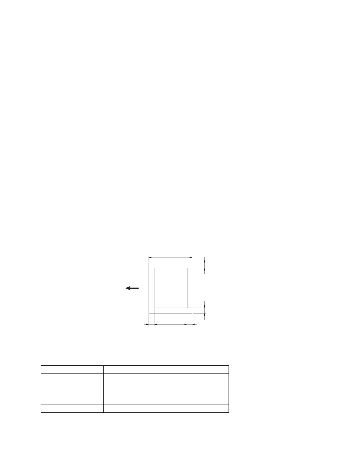
- Effective scanning area
A
Scanning
direction
B
(
Mechanical system error ±2 mm included
Fig. 1-1
Original size A B
A4 210 204.5
B4 364 358.5
A3 420 414.5
FOLIO 330 324.5
LT 216 210.5
2
3
2.53
)
(mm)
GD-1210/1250/1270/1160/1260 © 2006 - 2011 TOSHIBA TEC CORPORATION All rights reserved
SPECIFICATIONS AND OUTLINE OF SYSTEM
1 - 2
Page 11
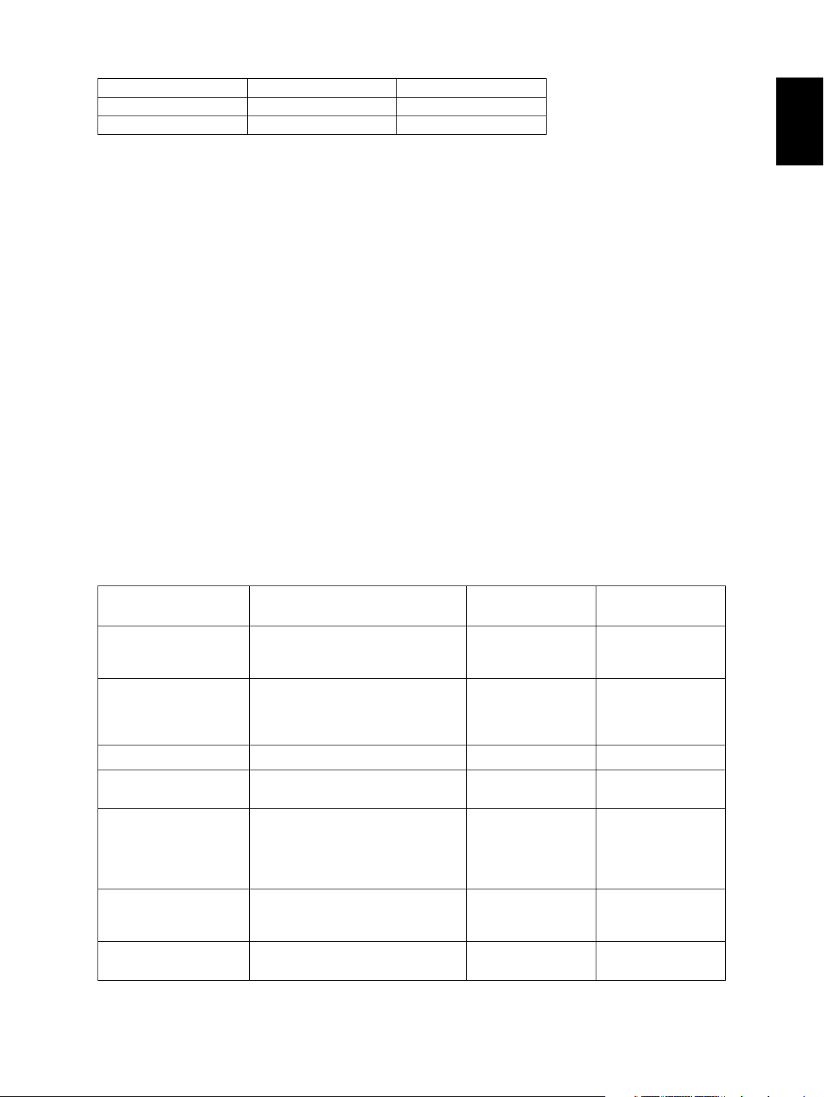
Original size A B
LG 355.6 350.1
LD 431.8 426.3
3) Transmission system
Circuits to be used: Subscriber line/FAX communication network (G3)
- Calling automatic transmission (including the sequential multi-address transmission)
- Calling automatic reception (polling reception)
- Called automatic transmission (polling transmission)
- Called automatic reception
- Calling manual transmission
- Calling manual reception
- Called manual transmission
- Called manual reception
Communication mode
High-speed mode (Toshiba original procedure mode)
G3 mode
ECM (Error Correction Mode)
Circuit carrier link equalization function
Embedded
Output level
–16 dBm to –8 dBm (The setting can be changed by “1 dB”.)
1
Input level
–43 dBm to 0 dBm
(Level –55 dBm or lower cannot be detected)
Specifications of the communication mode
High-speed mode
(Toshiba original procedure mode)
Horizontal scanning density
Vertical scanning density 3.85 lines/mm
Encoding system MH/MR/MMR/JBIG MH/MR MH/MR/MMR/JBIG
Minimum transmission
time for 1 line
Transmission speed
(image signal) and modulation method
Control signal 300 bps
Conformance to V.17/V.29/V.27 ter
8 dots/mm
300 dpi (Reception only)
16 dots/mm
7.7 lines/mm
300 dpi (Reception only)
15.4 lines/mm
2.5 ms Same as on the left Same as on the left
14.4 k/12 k/9600
7200/4800/2400 bps
V.21
G3 mode ECM
Same as on the left Same as on the left
Same as on the left Same as on the left
Same as on the left 33.6 k/31.2 k/28.8 k/
26.4 k/24 k/21.6 k/
19.2 k/16.8 k/14.4 k/
12 k/9600/7200/
4800/2400 bps
Same as on the left 2400/1200/600/
300 bps
V.34/V.8/V.21
Procedure to control the
transmission
© 2006 - 2011 TOSHIBA TEC CORPORATION All rights reserved GD-1210/1250/1270/1160/1260
Toshiba original procedure T.30 conformance Same as on the left
SPECIFICATIONS AND OUTLINE OF SYSTEM
1 - 3
Page 12

4) Recording paper
- Recording method
Electrophotographic recording method by LSU (Laser Scanning Unit)
- Horizontal printing density
24 lines/mm (96 lines/mm with the smoothing processing)
[23.1 lines/mm (92.4 lines/mm with the smoothing processing)]
- Vertical printing density
23.1 lines/mm (24 lines/mm with the smoothing processing)
- Recording paper size and the effective printing area
Unit: mm (inch)
Paper size Dimension (width x length) Printing area
A5-R 148 x 210 143 x 204.5
B5-R 182 x 257 177 x 251.5
B5 257 x 182 252 x 176.5
A4-R 210 x 297 205 x 291.5
A4 297 x 210 292 x 204.5
B4 257 x 364 252 x 358.5
A3 297 x 420 292 x 414.5
FOLIO 210 x 330 205 x 324.5
ST-R 139.7 x 216 (5.5 x 8.5) 134.7 x 210.5
LT-R 216 x 279.4 (8.5 x 11) 211 x 273.9
LT 279.4 x 216 (11 x 8.5) 274.4 x 210.5
LG 216 x 355.6 (8.5 x 14) 211 x 350.1
LD 279.4 x 431.8 (11 x 17) 274.4 x 426.3
COMP 257 x 356 (10.125 x 14) 252 x 350.5
GD-1210/1250/1270/1160/1260 © 2006 - 2011 TOSHIBA TEC CORPORATION All rights reserved
SPECIFICATIONS AND OUTLINE OF SYSTEM
1 - 4
Page 13

1.3 Features
• A3/LD scanning
Scans data across A3/LD width and transmits in A3/LD actual size.
• High-speed scanning
Inputs an A4/LT-size transmitted document in about 0.7 seconds (A4/LT document transmitted
widthwise).
• High-speed transmission
33.6 Kbps high speed modem
Toshiba original high-speed communication modes EX and HS
JBIG encoding system
• Dual Access
- FAX transmission
There are two types of FAX transmission: Page-by-page direct transmission and memory transmission that all pages are stored in the memory before being transmitted.
- FAX reception
Basically, all pages are input in the memory before being output. This reduces the time that the
FAX communication occupies the machine, making Dual Access between the copying/faxing and
printing operation possible.
Namely, the followings are possible:
- Memory input during the memory transmission
- Memory input during the memory reception
- Copying during the memory transmission
- Reception during the copying
- Reception during the memory output
- Reception during the list output
1
• Laser printing on plain paper
Printing is made on the standard size paper (A3/LD, B4/COMP, A4/LT/LG, A4-R/LT-R, B5, B5-R,
FOLIO, and A5-R/ST-R) with the laser system.
•Gradation
256 tones, error diffusion method
• Memory communication function
Image data can be stored in the HDD. In the delayed transmission, image data read from an original
are stored in the memory, then sent when the specified time comes.
Other memory functions: multi transmission, memory reception, ECM communication, etc.
• Smoothing
The smoothing process is applied to the received images so that they are changed from 8 × 3.85,
8 × 7.7, 8 × 15.4 or 16 × 15.4 to 24 × 92.4 (equivalent to 600 × 2400dpi), then printed out.
• Editing function
Duplex transmission and duplex printing are possible.
• FAX data file storage capacity
1 GB (for transmission and reception)
Note: Note:
For hard drivers, GB means 1 billion bytes.
© 2006 - 2011 TOSHIBA TEC CORPORATION All rights reserved GD-1210/1250/1270/1160/1260
1 - 5
11/04
SPECIFICATIONS AND OUTLINE OF SYSTEM
Page 14

• Phone Book (3,000 addresses)
Up to 3,000 addresses can be registered in the Phone Book using the large LCD control panel.
• Multi-address transmission function
Data are sent to multiple addresses (400 destinations) in sequence in a single operation.
There are three ways to choose/enter the address
- Choose from the Phone Book (up to 400 destinations)
- Direct dialing (up to 400 destinations)
- Mix operation (Phone Book, Direct dialing, Group destinations: up to 400 destinations)
• Memory reception function
When the recording paper has run out or a paper jam has occurred, the memory receives and stores
the data.
• Auto-dialing function
- Delayed dialing
Documents are transmitted automatically to the preset number at the preset time.
- Redialing
When the receiving side is busy during the automatic dialing, the machine keeps dialing at a
fixed interval for a specified number of times.
• Receiving tone/completion tone
Sound notifies that the reception of a FAX document or printing of a received document has been
completed.
• List output
The following data stored in the RAM can be printed out
- Phone book information
- Function list
- Transmission journal
- Reception journal
- Memory transmission report
- Power failure list etc.
• Power saver mode
During hours in which the reception amount is small, the weekly timer works to shut off the main
power and the heater power to save power consumption.
• Drawer selection
It is possible to choose a drawer on to whose paper the received images are to be printed.
[Options]
• 2nd line
One extra line can be added by installing the 2nd line unit (option).
GD-1210/1250/1270/1160/1260 © 2006 - 2011 TOSHIBA TEC CORPORATION All rights reserved
SPECIFICATIONS AND OUTLINE OF SYSTEM
1 - 6
11/04
Page 15

1.4 Accessories and Parts
The following accessories and parts come with the FAX unit:
Accessory GD-1210 GD-1250 GD-1270
1
Operator’s manual (for facsimile function) 1 pc.
Modular cord (2 m) 1 pc.
Unpacking instruction 1 set
Parts GD-1210 GD-1250 GD-1270
Fax unit 1 pc.
SG3 label 1 pc.
FCC Part 68 label (U.S.A.) / IC label (Canada): NA only 1 pc.
DTS label (EU): EU only 1 pc.
Teleprompt label (New Zealand): AU only 1 pc.
Notice to users label (New Zealand): AU only
Screw 5 pc.
Ground plate 1 pc.
Gasket 1 pc. 1 pc. -
Ferrite core
Bracket -
1 pc. 1 pc. 1 pc.
-1 pc.-
1 pc. 1 pc.
1 pc. 1 pc.
1 set 1 set
1 pc. 1 pc.
1 pc. 1 pc.
1 pc. 1 pc.
1 pc. 1 pc.
1 pc. 1 pc.
5 pc.
1 pc. -
-2 pc.
4 pc.
Harness clamp
Cover
- - 1 pc.
- - 3 pc.
* Apply the each label to the specified positions following the Unpacking/Setup Instruction.
© 2006 - 2011 TOSHIBA TEC CORPORATION All rights reserved GD-1210/1250/1270/1160/1260
1 - 7
09/05
SPECIFICATIONS AND OUTLINE OF SYSTEM
Page 16

1.5 Options
Extends the FAX functions when the FAX unit is installed.
Option Function
e-STUDIO2500c/
3500c/3510c
e-STUDIO2330C/
2820C/2830C/
3520C/3530C/
4520C
e-STUDIO5520C/
6520C/6530C
Reversing Automatic
Feeds originals MR-3018 MR-3018 Document Feeder
(RADF)
Finisher Sorts out docu-
ments to be output
for the FAX/copy-
ing operation
2nd line for FAX unit Adds one extra
communication line
Option Function
Reversing Automatic
Feeds originals MR-3021/3022 Document Feeder
(RADF)
Finisher Sorts out docu-
ments to be output
for the FAX/copy-
ing operation
2nd line for FAX unit Adds one extra
communication line
MJ-1101
MJ-1030
MJ-1101
MJ-1030
MJ-1031
GD-1160 GD-1260 GD-1260
e-STUDIO205L/255/305/355/
455
MJ-1101
MJ-1031
MJ-1024
e-STUDIO555/655/755/855
MJ-1027
MJ-1028
MJ-1029
MJ-1025
MJ-5004
MJ-5005
MJ-5006
GD-1260 GD-1260
MJ-1103
MJ-1104
Option Function
Reversing Automatic
Document Feeder
e-STUDIO2040C/
2540C/3040C/
3540C/4540C
Feeds originals MR-3021
MR-3022
e-STUDIO5540C/
6540C/6550C
-
e-STUDIO556/656/
756/856
-
(RADF)
Finisher Sorts out docu-
ments to be output
for the FAX/copy-
MJ-1101
MJ-1031
MJ-1106
MJ-1103
MJ-1104
MJ-1027
MJ-1028
MJ-1029
ing operation
2nd line for FAX unit Adds one extra
GD-1260 GD-1260
GD-1260
communication line
GD-1210/1250/1270/1160/1260 © 2006 - 2011 TOSHIBA TEC CORPORATION All rights reserved
SPECIFICATIONS AND OUTLINE OF SYSTEM
1 - 8
11/12
Page 17

Option Function
e-STUDIO206L/256/306/356/
456
1
Reversing Automatic
Feeds originals MR-3021/3022
Document Feeder
(RADF)
Finisher Sorts out docu-
ments to be output
for the FAX/copy-
ing operation
2nd line for FAX unit Adds one extra
communication line
MJ-1101
MJ-1106
MJ-1032
MJ-1033
MJ-5004
MJ-5005
MJ-5006
GD-1260
© 2006 - 2011 TOSHIBA TEC CORPORATION All rights reserved GD-1210/1250/1270/1160/1260
1 - 9
11/12
SPECIFICATIONS AND OUTLINE OF SYSTEM
Page 18
1.6 System List
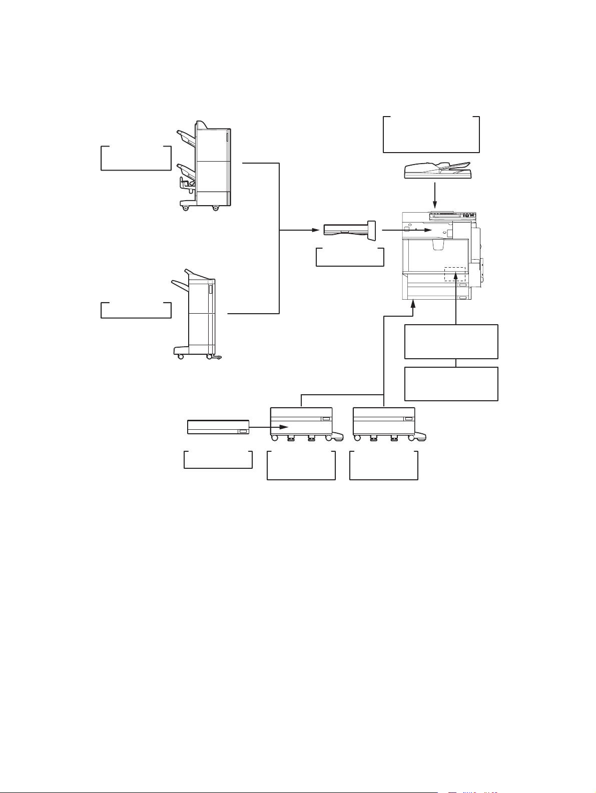
1.6.1 e-STUDIO2500c/3500c/3510c
Saddle stitch
finisher
MJ-1030
Finisher
MJ-1101
Bridge Kit
KN-3500
Reversing Automatic
Document Feeder
(
)
RADF
MR-3018
FAX
GD-1210NA/AU/AS/
unit
EU/C/TW/KR
Drawer Module
MY-1031/C
Paper Feed
Pedestal (PFP
KD-1018/C
Fig. 1-2
)
KD-1019 A4/LT/C
Large Capacity
Feeder (LCF
2nd Line for FAX
GD-1160
NA/EU-N/C/TW
)
unit
GD-1210/1250/1270/1160/1260 © 2006 - 2011 TOSHIBA TEC CORPORATION All rights reserved
SPECIFICATIONS AND OUTLINE OF SYSTEM
1 - 10
08/04
Page 19
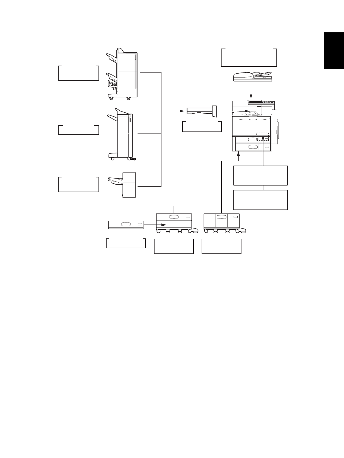
1.6.2 e-STUDIO2330C/2820C/2830C/3520C/3530C/4520C
Saddle stitch
finisher
MJ-1030
Finisher
MJ-1101
Hanging
finisher
MJ-1031
Bridge Kit
KN-4520
Reversing Automatic
Document Feeder
(
)
RADF
MR-3018
FAX
GD-1250NA/AU/AS/
2nd Line for FAX
NA/AU/EU/C/TW
unit
EU/C/TW
GD-1260
1
unit
Drawer Module
MY-1032/C
Paper Feed
Pedestal (PFP
KD-1023/C
Fig. 1-3
)
KD-1024 A4/LT/C
Large Capacity
Feeder (LCF
)
© 2006 - 2011 TOSHIBA TEC CORPORATION All rights reserved GD-1210/1250/1270/1160/1260
1 - 11
08/04
SPECIFICATIONS AND OUTLINE OF SYSTEM
Page 20
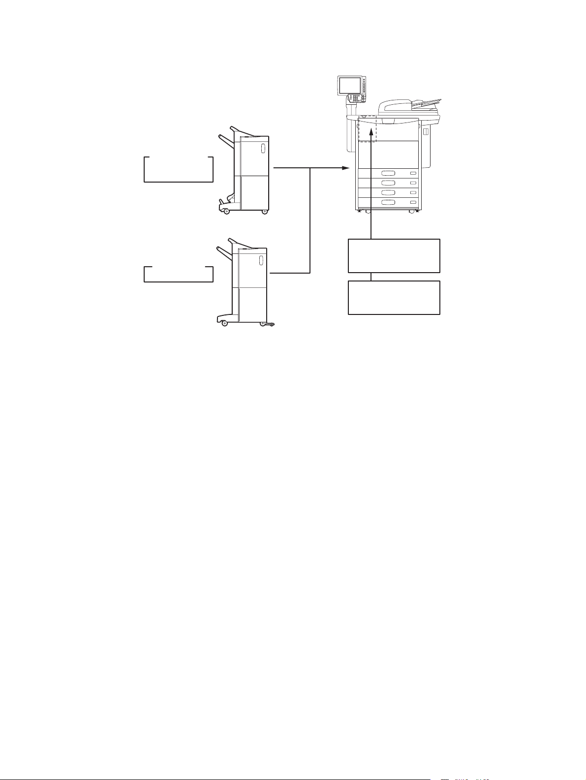
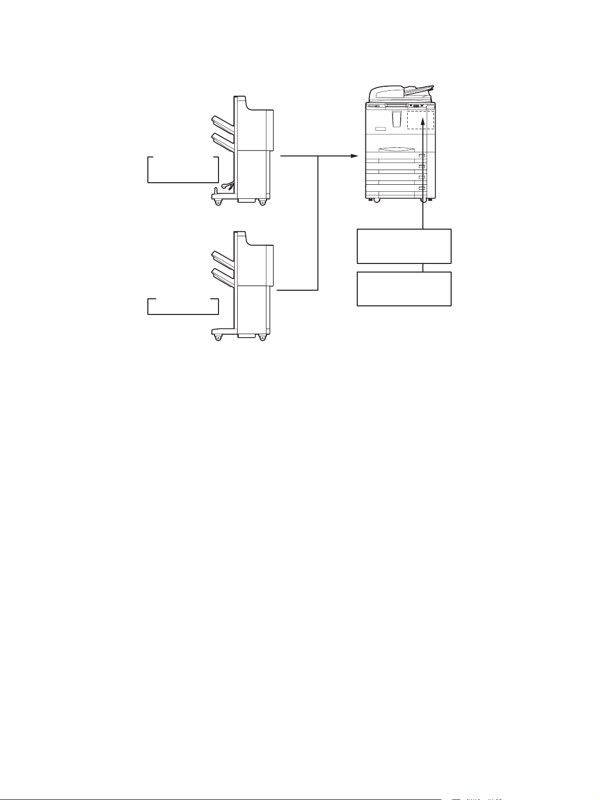
1.6.3 e-STUDIO5520C/6520C/6530C
Saddle stitch
finisher
MJ-1104
Finisher
MJ-1103
Fig. 1-4
FAX
GD-1270NA/AU/AS/
2nd Line for FAX
NA/AU/EU/C/TW
unit
EU/C/TW
GD-1260
unit
GD-1210/1250/1270/1160/1260 © 2006 - 2011 TOSHIBA TEC CORPORATION All rights reserved
SPECIFICATIONS AND OUTLINE OF SYSTEM
1 - 12
09/05
Page 21
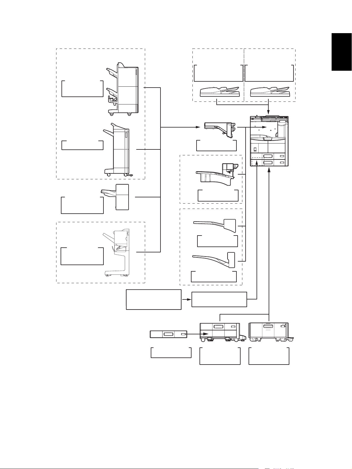
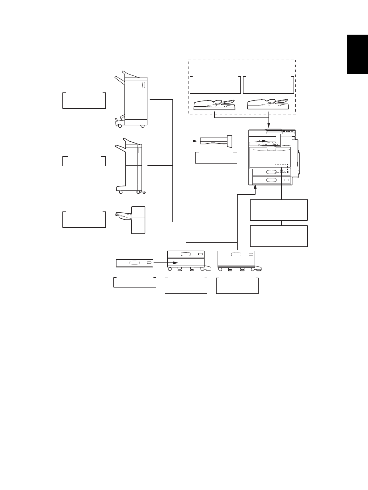
1.6.4 e-STUDIO205L/255/305/355/455
e-STUDIO355/455
Saddle stitch
Finisher
MJ-1024
Finisher
MJ-1101
Finisher
(
Hanging type
MJ-1031
e-STUDIO355/455
Reversing Automatic
Document Feeder (RADF
MR-3022
Bridge Kit
KN-2520
e-STUDIO355/455
Job Separator
)
e-STUDIO205L/255/355
MJ-5006
e-STUDIO205L/255/355
Reversing Automatic
)
Document Feeder (RADF
MR-3021
)
1
e-STUDIO205L/255/305
Saddle stitch
Finisher
MJ-1025
2nd Line for
FAX Unit
GD-1260
Drawer Module
MY-1033
Fig. 1-5
Job Separator
MJ-5004
Offset Tray
MJ-5005
FAX Unit
GD-1250
Paper Feed
Pedestal (PFP)
KD-1025
Large Capacity
Feeder (LCF)
KD-1026
© 2006 - 2011 TOSHIBA TEC CORPORATION All rights reserved GD-1210/1250/1270/1160/1260
1 - 13
11/12
SPECIFICATIONS AND OUTLINE OF SYSTEM
Page 22
1.6.5 e-STUDIO555/655/755/855
Saddle stitch
finisher
MJ-1028/1029
FAX
GD-1250NA/EU/AU/AS/C
unit
Finisher
MJ-1027
Fig. 1-6
2nd Line for FAX
GD-1260
NA/EU-N/AU/C
unit
GD-1210/1250/1270/1160/1260 © 2006 - 2011 TOSHIBA TEC CORPORATION All rights reserved
SPECIFICATIONS AND OUTLINE OF SYSTEM
1 - 14
09/05
Page 23
1.6.6 e-STUDIO2040C/2540C/3040C/3540C/4540C
e-STUDIO3540C/4540C
Reversing Automatic
Document Feeder (RADF
Saddle stitch
finisher
MJ-1106
MR-3022
e-STUDIO2040C/2540C
/3040C
Reversing Automatic
)
Document Feeder (RADF
MR-3021
1
)
Finisher
MJ-1101
Hanging
finisher
MJ-1031
Drawer Module
MY-1035/C
Paper Feed
Pedestal (PFP
KD-1027/C
Fig. 1-7
Bridge Kit
KN-4530
)
KD-1028 A4/LT/C
Large Capacity
Feeder (LCF
FAX
GD-1250NA/AU/AS/
2nd Line for FAX
NA/AU/EU/C/TW
)
unit
EU/C/TW
GD-1260
unit
© 2006 - 2011 TOSHIBA TEC CORPORATION All rights reserved GD-1210/1250/1270/1160/1260
1 - 15
11/04
SPECIFICATIONS AND OUTLINE OF SYSTEM
Page 24

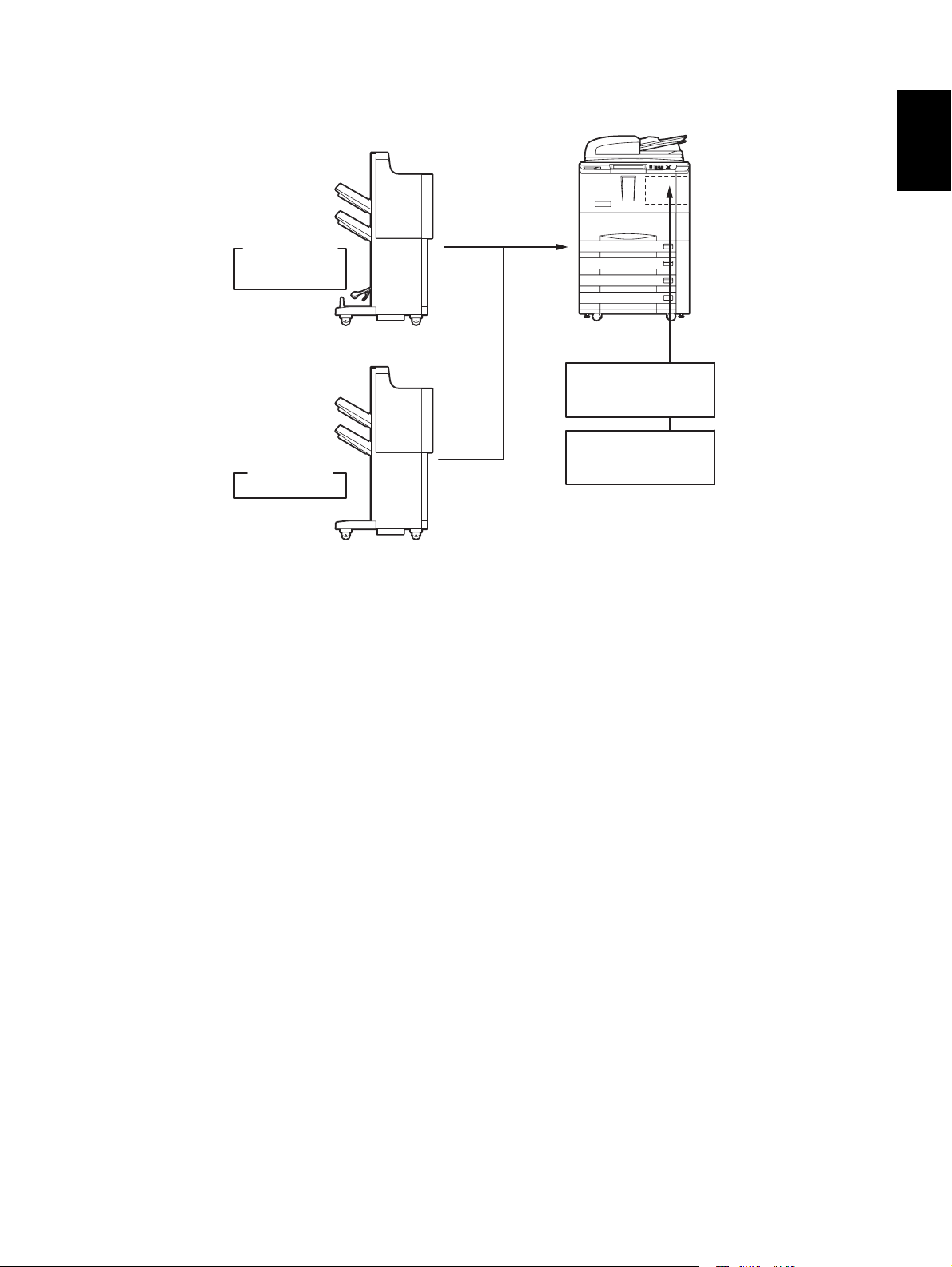
1.6.7 e-STUDIO5540C/6540C/6550C
Saddle stitch
finisher
MJ-1104
Finisher
MJ-1103
Fig. 1-8
FAX
GD-1270NA/AU/AS/
2nd Line for FAX
NA/AU/EU/C/TW
unit
EU/C/TW
unit
GD-1260
GD-1210/1250/1270/1160/1260 © 2006 - 2011 TOSHIBA TEC CORPORATION All rights reserved
SPECIFICATIONS AND OUTLINE OF SYSTEM
1 - 16
11/04
Page 25
1.6.8 e-STUDIO556/656/756/856
Saddle stitch
finisher
MJ-1028/1029
FAX
GD-1250NA/EU/AU/AS/C
unit
1
Finisher
MJ-1027
Fig. 1-9
2nd Line for FAX
GD-1260
NA/EU-N/AU/C
unit
© 2006 - 2011 TOSHIBA TEC CORPORATION All rights reserved GD-1210/1250/1270/1160/1260
1 - 17
11/12
SPECIFICATIONS AND OUTLINE OF SYSTEM
Page 26
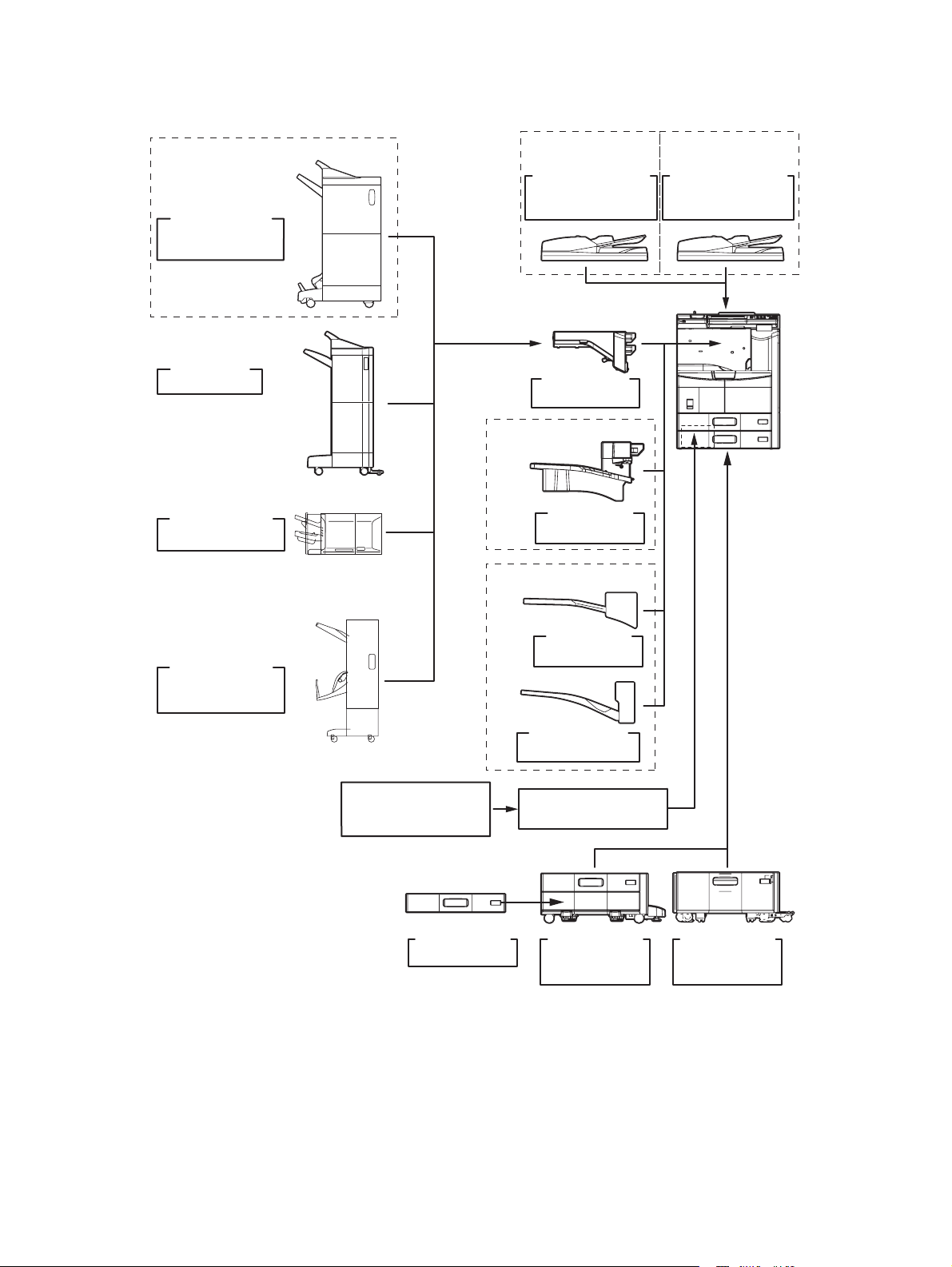
1.6.9 e-STUDIO206L/256/306/356/456
e-STUDIO356/456
Saddle stitch
Finisher
MJ-1106/C
Finisher
MJ-1101
Inner Finisher
MJ-1032
e-STUDIO356/456
Reversing Automatic
Document Feeder (RADF
MR-3022
Bridge Kit
KN-2520
e-STUDIO356/456
Job Separator
MJ-5006
e-STUDIO206L/256/356
e-STUDIO206L/256/356
Reversing Automatic
)
Document Feeder (RADF
MR-3021
)
Saddle stitch
Finisher
MJ-1033
2nd Line for
FAX Unit
GD-1260
Drawer Module
MY-1033
Fig. 1-10
Job Separator
MJ-5004
Offset Tray
MJ-5005
FAX Unit
GD-1250
Paper Feed
Pedestal (PFP)
KD-1025
Large Capacity
Feeder (LCF)
KD-1026
GD-1210/1250/1270/1160/1260 © 2006 - 2011 TOSHIBA TEC CORPORATION All rights reserved
SPECIFICATIONS AND OUTLINE OF SYSTEM
1 - 18
11/12
Page 27
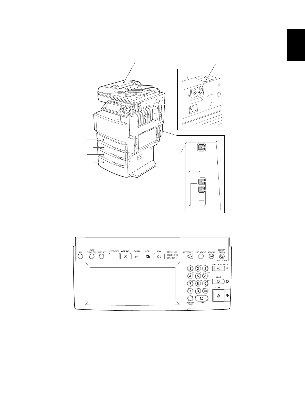
1.7 Overview
r
1.7.1 e-STUDIO2500c/3500c/3510c
Reversing automatic document feeder
Drawers
Paper feed pedestal
or
Large capacity feeder
1
Power switch
LINE2 connecto
LINE connector
TEL connector
Fig. 1-11
Fig. 1-12
© 2006 - 2011 TOSHIBA TEC CORPORATION All rights reserved GD-1210/1250/1270/1160/1260
1 - 19
09/05
SPECIFICATIONS AND OUTLINE OF SYSTEM
Page 28
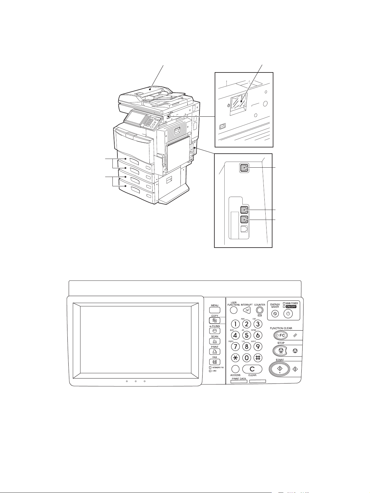
1.7.2 e-STUDIO2330C/2820C/2830C/3520C/3530C/4520C, e-
r
STUDIO2040C/2540C/3040C/3540C/4540C
Drawers
Paper feed pedestal
or
Large capacity feeder
Reversing automatic document feeder
Power switch
LINE2 connecto
LINE connector
TEL connector
Fig. 1-13
Fig. 1-14
GD-1210/1250/1270/1160/1260 © 2006 - 2011 TOSHIBA TEC CORPORATION All rights reserved
SPECIFICATIONS AND OUTLINE OF SYSTEM
1 - 20
11/04
Page 29
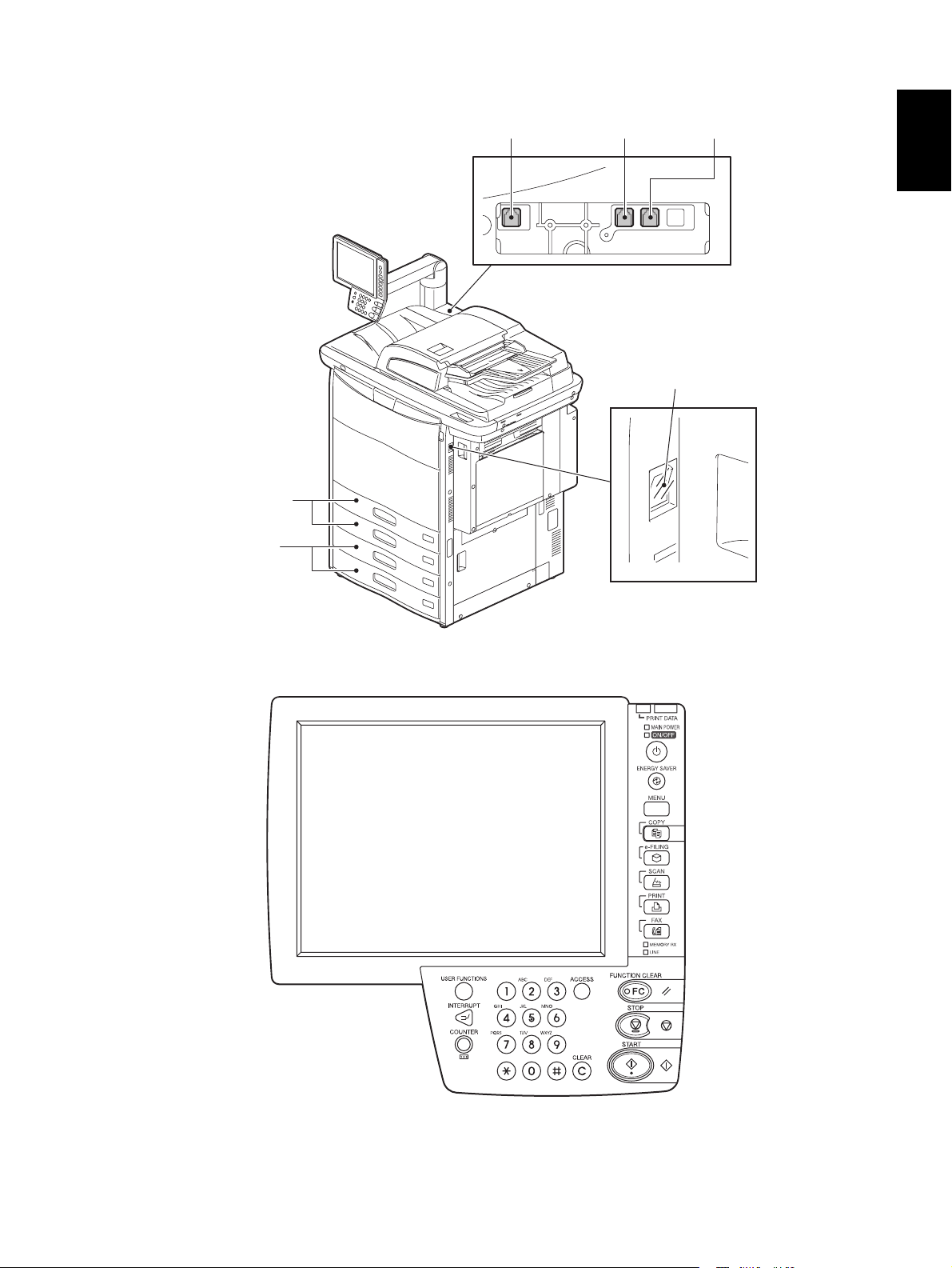
1.7.3 e-STUDIO5520C/6520C/6530C, e-STUDIO5540C/6540C/6550C
r
Drawers
Drawers
or
Large capacity feeder
LINE2 connector
LINE connector TEL connecto
Power switch
1
Fig. 1-15
Fig. 1-16
© 2006 - 2011 TOSHIBA TEC CORPORATION All rights reserved GD-1210/1250/1270/1160/1260
1 - 21
11/04
SPECIFICATIONS AND OUTLINE OF SYSTEM
Page 30

1.7.4 e-STUDIO205L/255/305/355/455, e-STUDIO206L/256/306/356/456
Power switch
TEL connector
LINE connector
LINE2 connector
Fig. 1-17
Fig. 1-18
GD-1210/1250/1270/1160/1260 © 2006 - 2011 TOSHIBA TEC CORPORATION All rights reserved
SPECIFICATIONS AND OUTLINE OF SYSTEM
1 - 22
11/12
Page 31

1.7.5 e-STUDIO555/655/755/855, e-STUDIO556/656/756/856
Power switch
1
LINE2 connector
LINE connector
TEL connector
Fig. 1-19
Fig. 1-20
© 2006 - 2011 TOSHIBA TEC CORPORATION All rights reserved GD-1210/1250/1270/1160/1260
1 - 23
11/12
SPECIFICATIONS AND OUTLINE OF SYSTEM
Page 32

1.8 Layout of PC Boards
e-STUDIO2500c/3500c/3510c
e-STUDIO2330C/2820C/2830C/3520C/3530C/4520C
e-STUDIO2040C/2540C/3040C/3540C/4540C
FAX
NCU
FAX PWR
MDM
e-STUDIO205L/255/305/355/455
e-STUDIO206L/256/306/356/456
e-STUDIO5520C/6520C/6530C
e-STUDIO5540C/6540C/6550C
NCU
FAX
MDM
FAX PWR
e-STUDIO555/655/755/855
e-STUDIO556/656/756/856
MDM
FAX
MDM
FAX
FAX PWR
NCU
NCU
Fig. 1-21 Rear side of the equipment
Symbol Name Function
FAX FAX board Controls the FAX function
MDM MDM board Control the MODEM function (for 2nd line)
NCU1 NCU1 board Control the line of telephone (for 1st line)
NCU2 NCU2 board Control the line of telephone (for 2nd line)
FAX PWR FAX power board Supplies the power (-12V, +24V) of FAX
FAX PWR
GD-1210/1250/1270/1160/1260 © 2006 - 2011 TOSHIBA TEC CORPORATION All rights reserved
SPECIFICATIONS AND OUTLINE OF SYSTEM
1 - 24
11/12
Page 33

2. LSU-RELATED FUNCTIONS
2.1 Recording Mode
This machine offers various printing modes such as the selection of the applicable recording paper and
the recording method, etc. to meet users’ needs. To take full advantage of these features, it is important
to understand the concepts of the recording paper selection algorithm and printing algorithm as
described in 2. 2.
2
© 2006 - 2011 TOSHIBA TEC CORPORATION All rights reserved GD-1210/1250/1270/1160/1260
2 - 1
LSU-RELATED FUNCTIONS
Page 34

2.2 Recording Paper Selection Algorithm and Printing Algorithm
Before printing the received image, the preset settings are evaluated in the order of the following 1) and
2), and the printing is performed based on the result.
1) Recording paper selection algorithm
- Basically, the received image is printed on a sheet of paper of the same size as the original.
However, if this size is not available, this algorithm determines on which size of recording paper
the output should be made. (Actual Size Mode/Free Mode)
2) Printing algorithm
- Determines how the received image is to be printed. (Discard printing/Vertical reduction printing/
Regular size reduction printing/Split printing)
2.2.1 Recording paper selection algorithm
It is possible to distinguish the size of each received image (A3(LD)/B4(LG)/A4(LT)/B5/A5). Basically,
recording paper of the same size as the original is used for printing. If recording paper of the size is not
available, this algorithm selects paper of another size according to the setting in the Setting Mode.
1) Actual Size Mode (13-517: 0)
- Printing is performed when regular size reduction is not applied to the received image. In this
mode, an A4/LT received image is printed on a B4 recording paper.
2) Free Mode (13-517: 1)
- Printing is performed on any available recording paper.
2.2.2 Printing algorithm
Recording paper has its effective printing area. Even if the size of the original paper and the recording
paper are the same, the length of the original is normally longer.
This means that the received image would be divided onto two sheets. To prevent this, the printing
algorithm works as described in the following pages.
GD-1210/1250/1270/1160/1260 © 2006 - 2011 TOSHIBA TEC CORPORATION All rights reserved
LSU-RELATED FUNCTIONS
2 - 2
Page 35

Discard / Vertical reduction / Regular size reduction / Split printing flow chart
START
Recording
paper of the same
size as the original's
available?
Yes
No
1
Smaller size paper
available?
Yes
No
Larger size paper
available?
No
Recording
paper run out
Yes
1
2
Received image fitsin
the effective printing area of the
recording paper?
Use the short
length paper?
(
See the note below.
No
Discard
printing function
Blank
space *within the
discard parameter?
Vertical reduction
function ON?
ON?
No
No
Yes
No
Regular size
reduction function
ON?
Normal (actual size
Yes
Yes
)
Yes
No
printing
Discard printing
(
actual size
)
)
No
Image not
output
Regular
size reduction
function ON?
Yes
Regular size
reduction printing
Regular size
reduction function
ON?
Yes
No
No
Regular size
reduction printing
Image not
output
Image not
output
Yes Yes
Reduction ratio "R"
calculated from the
actual image data.
"R" within the max.
reduction ratio?
Yes
Vertical reduction
printing
No
Note: Short length paper are the recording paper of A4/B5/A5/LT/
ST against A3/B4/A4/LD/LT size originals respectively.
© 2006 - 2011 TOSHIBA TEC CORPORATION All rights reserved GD-1210/1250/1270/1160/1260
Regular size
reduction
printing
LSU-RELATED FUNCTIONS
2 - 3
Page 36

1) Discard printing
- Since the trailing edge area of the original is normally blank, this blank area is cut off to allow the
image fit in one sheet in this mode. Image reduction is not performed.
- Maximum discarding amount:
0 mm: Discard not performed
10 mm: Corresponding to the inside the TTI
18 mm: Corresponding to the outside the TTI 1
22 mm: Corresponding to the outside the TTI 2
34 mm: A4 → LT conversion
(TTI: Transmission Terminal Identifier)
When the discard function is ON (13–378:1):
Actual size recording is performed with no vertical reduction nor division. The original image is
recorded as it is. Namely, the data exceeding the effective printing area are discarded.
A
B
Area B is discarded.
A : Effective printing length
B : Recording data length outside the
effective printing area
(
A + B = Recording data length
Fig. 2-1
A
)
Discard parameter (13-375: 0 to 4)
The following parameters are available:
Discard function Length of B (Discard parameter) Set value
OFF 0 mm 0
ON 10 mm 1
18 mm 2
22 mm 3
34 mm 4
Reference: These parameters should be set by the service technician (in the FAX Function Mode).
2) Vertical reduction printing (13–377: 0)
- The recording data length is reduced so that the image fits in the recording paper.
The data can be reduced up to 90/75%, and the machine automatically selects the appropriate
ratio.
GD-1210/1250/1270/1160/1260 © 2006 - 2011 TOSHIBA TEC CORPORATION All rights reserved
LSU-RELATED FUNCTIONS
2 - 4
Page 37

3) Regular size reduction printing (13–517: 1)
- When the discard and vertical reduction printing cannot be applied to the received image, and
any of the combinations A3 → B4, A3 → A4, B4 → A4, B4 → B5, B4 → A5, A4 → B5, A4 → A5,
COMP → LT, COMP → ST, LD → COMP, LD → LG/LT, LD → ST, LT → ST, FOLIO → B5, FOLIO
→ A5 is satisfied, the regular size reduction printing is performed.
In case that the recording data length is within the effective printing length A, but the recording
paper of the same size as the original’s or larger size is not available;
2
A
B
A × reduction
ratio
B × reduction
ratio
A3 B4, A3
A4
B4 A4, B4 B5, B4 A5, A4 B5,
A4 A5 , COMP
LD COMP, LD
LT ST, FOLIO
Fig. 2-2
LT, COMP ST,
LG/LT, LD
B5, FOLIO
ST,
A5
In case that the recording data length exceeds the effective printing length A, the vertical reduction printing is not applicable and larger size recording paper is not available;
(In the following example, A4/LT original was sent but the recording length exceeds A4 size and
the data do not fit in A4/LT even if the vertical reduction is performed. The reduction B4 → A4 or
A3 → A4 is applied in this case.)
A
C
B
A × reduction
ratio
C × reduction
ratio
D
B × reduction
ratio
D × reduction
ratio
Fig. 2-3
© 2006 - 2011 TOSHIBA TEC CORPORATION All rights reserved GD-1210/1250/1270/1160/1260
2 - 5
LSU-RELATED FUNCTIONS
Page 38

4) Split printing
When the recording data do not fit in a recording paper even if vertical reduction is performed for the
recording data length (the recording data length is exceeding the effective printing length of the largest recording paper in the drawer installed in the machine), the recording data are divided onto two
sheets while vertical reduction is performed.
A
B
Fig. 2-4
A× vertical reduction ratio
B × vertical reduction ratio
2.2.3 Setting for the split recording
1) Split recording onto A4/B5/A5/ST
Set as to whether split recording onto the short length paper (A4/B5/A5/ST) is to be performed or
not.
When this function is disabled, split recording for A3/B4/A4 data onto A3/B4/A4/LG/LT recording
paper is not performed.
GD-1210/1250/1270/1160/1260 © 2006 - 2011 TOSHIBA TEC CORPORATION All rights reserved
LSU-RELATED FUNCTIONS
2 - 6
Page 39

2.3 Recording Paper and Function
The size of the recording paper on which the received image data are printed is determined according
to the presence/absence of the recording paper and the above-mentioned function settings. Relation
between the recording paper size and the function settings is described in this section.
2
© 2006 - 2011 TOSHIBA TEC CORPORATION All rights reserved GD-1210/1250/1270/1160/1260
2 - 7
LSU-RELATED FUNCTIONS
Page 40

2.3.1 Table of the recording paper selection modes
<Selection of recording paper: in case the recording data length do not exceed the effective recording
length of the recording paper>
Recording data size
A4-R B4 A3 LG LD
A4-R
1
A4
2
FOLIO
3
B4
4
B4
A3
A4-R
A4 A4 A4
*2
A3
*1
A4 B5
A4
A4-R A4-RB5-R
A3
*1 *2 *1 *1
FOLIO
*1 *1 *1 *1 *1 *1 *1
B5
B4
Priority
A3
5
*2 *2
FOLIOFOLIO
*1 *1
A4-R
B4
*1 *1 *1 *1
A5 LT ST
LT-R
A5
A4
FOLIO
B5
LT-R
LT
LG
COMP
LD
LT
LT-R
LD
LG
*2*1
COMP COMP
*2
LG
LD
LT-R
LT LT
COMP
COMP
LD
LT-RA4-R
LT
LG
LD ST
COMPCOMP
*1*2 *1
LG
LT-R
*1 *1 *2
LT-R
LT
LG
FOLIO
FOLIO
B4B4
*2
A3
*2
A4-R
A4
*1
*2
B4
*2
A3
*2*1 *1 *1
ST-R ST-R
*1*1 *1
*2
B5B5 B5 B5
6
*1 *1
B5-R B5-R B5-RB5-RB5-R
7
*1 *1 *1 *1
A5-R A5-R A5-R
8
A3 LD
*2
FOLIO
*1: Can be used when the regular size reduction function is ON (when it is OFF, the data are stored
in the memory.)
*2: When the data are output in the primary scanning direction, it is printed in the center of the
recording paper.
2.3.2 Others
1) For the users with the TTI outside setting, it is recommended to set the discard parameter to 18 mm.
GD-1210/1250/1270/1160/1260 © 2006 - 2011 TOSHIBA TEC CORPORATION All rights reserved
LSU-RELATED FUNCTIONS
2 - 8
*1
*1
Page 41

2.4 Energy Saver Mode
The fuser unit, main power and power supply for the control panel can be shut off during a specified
period of time such as night time that the machine is in the ready mode, using a weekly timer function of
the equipment. When a FAX is received in the Energy Saver Mode, the fuser unit, main power and
power supply for the control panel are automatically turned ON. Printing is then started when the
machine reaches the specified temperature. The Energy Saver Mode is useful for hours in which the
amount of communication is small and immediate printing is not necessary.
The setting of the Energy Saver Mode and time (start time, end time) are made on the USER FUNCTIONS screen. (Default setting is made by the weekly-timer function of the equipment.)
2
Energy Saver Mode
Auto Power
Save Mode
Sleep Mode Automatically or by
Super Sleep Mode Automatically or by
How to enter the
mode
Automatically Can be set in the
pressing the
[ENERGY SAVER]
button
pressing the [ON/OFF]
button for 2 seconds
Timer setting How to cancel the mode
Returns to the default screen by
USER FUNCTIONS
Screen.
Can be set in the
USER FUNCTIONS
Screen.
Can be set in the
USER FUNCTIONS
Screen.
receiving FAX document, or by
pressing the [START] button
Returns to the FAX screen by press-
ing the [FAX] button/
Returns to the default screen by
receiving FAX document, or by
pressing the [START] button
Returns to the FAX screen by press-
ing the [FAX] button.
Returns to the default screen by
receiving FAX document, or by
pressing the [ON/OFF] button.
© 2006 - 2011 TOSHIBA TEC CORPORATION All rights reserved GD-1210/1250/1270/1160/1260
2 - 9
11/04
LSU-RELATED FUNCTIONS
Page 42

2.5 Memory Reception
Basically, the receiving FAX data are once stored in the HDD, then the data are printed out after the
reception process is finished.
The memory reception is performed until the 1 GB HDD (for transmission and reception) becomes full.
GD-1210/1250/1270/1160/1260 © 2006 - 2011 TOSHIBA TEC CORPORATION All rights reserved
LSU-RELATED FUNCTIONS
2 - 10
11/04
Page 43

3. DIALING/COMMUNICATION CONTROL
3.1 Circuit Connection and Procedure to Change Mode
3.1.1 Dial call-up transmission to a telephone circuit
START
Detecting a calling signal?
NO
Detecting an off-hook signal?
NO
DC circuit closed
After detecting the dial tone,
or 3.3 seconds elapsed
Selection signal sent out
YES
YES
3
END
© 2006 - 2011 TOSHIBA TEC CORPORATION All rights reserved GD-1210/1250/1270/1160/1260
3 - 1
Standby state
DIALING/COMMUNICATION CONTROL
Page 44

3.1.2 Selection of the communication mode
This machine has three types of communication mode. The mode to be used is determined according
to the combination of the types of the circuits and communication and available function of the other
side’s machine.
Communication mode
Toshiba original procedure ECM G3
Telephone circuit {{{
3.1.3 Procedure to select the transmission mode
START
*1
Other side machine has the
Toshiba original
procedure mode?
YES
Communication using the
Toshiba original procedure
NO
Other side machine has
ECM mode?
NO
Other side machine has G3 mode?
YES
YES
ECM communication
G3 communication
*1: This step is only checked when the other side machine has CRP2 (+ CRP1) or when the trans-
mission is started by the CRP calling. (The first transmission to the other side with CRP1 only
is performed in the ECM mode.)
GD-1210/1250/1270/1160/1260 © 2006 - 2011 TOSHIBA TEC CORPORATION All rights reserved
DIALING/COMMUNICATION CONTROL
3 - 2
Page 45

3.2 Signaling System Diagram and Signal Forms
3.2.1 Circuit control signals
The following circuit control signals are used in the binary and tonal procedures.
• Circuit control signals
CED Called station identification
Indicates that the sender is a FAX machine in the automatic called
mode. (*1)
CNG Calling tone
Indicates that the sender is a FAX machine in the automatic calling
mode. (*1)
*1: This signal can be sent manually.
• Signal form
Signal name Signal form Signal form
3
CED f: 2100 ±15 Hz
CNG f: 1100 ±38 Hz
f
t
f
t
f
L
t
t: 2.6 - 4.0 sec
t: 0.5 sec ±15%
(L: 3 sec)
© 2006 - 2011 TOSHIBA TEC CORPORATION All rights reserved GD-1210/1250/1270/1160/1260
3 - 3
DIALING/COMMUNICATION CONTROL
Page 46

3.2.2 Communication with the binary signals
In the Toshiba original procedure/G3 modes, communication is performed with the binary procedure as
follows.
GD-1210/1250/1270/1160/1260 © 2006 - 2011 TOSHIBA TEC CORPORATION All rights reserved
DIALING/COMMUNICATION CONTROL
3 - 4
Page 47

(1) Binary procedure
• Transmission and reception in the Toshiba original procedure/G3 modes
Transmtter Receiver
CED
NSF•CSI•DIS
NSS•TSI•DCS
Training
TCF
CFR
Image signal
3
Mode ch a n ge pos s ible*
Informing that there is
the next page
EOM
MCF
NSF•CSI•DIS
NSS•TSI•DCS
Training
TCF
CFR
Image signal
MPS
MCF
Image signal
MCF
DCN
Fig. 3-1
* Mode change is possible only for the original set manually.
© 2006 - 2011 TOSHIBA TEC CORPORATION All rights reserved GD-1210/1250/1270/1160/1260
3 - 5
DIALING/COMMUNICATION CONTROL
Page 48

• Transmission and reception in the ECM mode
ECM (Error Correction Mode) conforms to T.30.
When an error has occurred to the received image data, the receiving station informs the
sending station of the occurrence of the error, and the sending station sends the image data
again.
Transmtter Receiver
CED
NSF•CSI•DIS
NSS•TSI•DCS
Training
TCF
CFR
Only error frame retransmitted
Page 1 completed
Page 2 completed
Image s
Image s
ignal
PPS NULL
MCF
Image signal
PPS MPS
PPR
ignal retransmitted
PPS MPS
MCF
Image signal
PPS EOP
MCF
DCN
256 frames received
Error occurred
Fig. 3-2
GD-1210/1250/1270/1160/1260 © 2006 - 2011 TOSHIBA TEC CORPORATION All rights reserved
DIALING/COMMUNICATION CONTROL
3 - 6
Page 49

• Cancellation during the transmission
If the [STOP] button is pressed during the direct transmission or memory input, the display to
confirm the cancellation appears. The communication is finished normally regardless of the
presence/absence of the next page or mode changes by pressing the [STOP] button.
If the [STOP] button is pressed anytime except during the transmission of the image data,
DCN is forcibly sent to terminate the communication.
Press the [JOB STATUS] button, and select the transmission job to cancel, then press the
[CANCEL] button on the LCD display to cancel the memory transmission or polling transmission.
Transmtter
[
JOB STATUS] button
[
CANCEL] button
CED
NSF•CSI•DIS
NSS•TSI•DCS
Training
TCF
CFR
Image signal
EOP
MCF
DCN
Receiver
3
Fig. 3-3
© 2006 - 2011 TOSHIBA TEC CORPORATION All rights reserved GD-1210/1250/1270/1160/1260
3 - 7
DIALING/COMMUNICATION CONTROL
Page 50

(2) Binary signals
NSF Non-Standard Facility
Informs that the receiving station (machine) has a non-standard facility.
NSC Non-Standard Facility Command
Command to transmit using the non-standard facility which is selected corresponding to
NSF (i.e., Polling etc.).
NSS Non-Standard Facility Setup
Command to transmit using the non-standard facility which is selected corresponding to
NSF or NSC.
CSI Called Subscriber Identification
Provides the telephone number of the called station. Used to check the identity of the called
station.
CIG Calling Subscriber Identification
Provides the telephone number of the calling station. Used to check the identity of the calling station (Polling, etc.).
TSI Transmitting Station Identification
Provides the telephone number of transmitting station. Used to check the identity of the
transmitting station.
DIS Digital Identification Signal
Informs that the receiving station (machine) has a standard facility (G3/G2).
DTC Digital Transmit Command
Command to transmit using the standard facility which is selected corresponding to DIS
(i.e., Polling, etc.).
DCS Digital Command Signal
Commands to transmit using the standard facility which is selected corresponding to DIS or
DTC.
SUB Sub-address
Indicates that the FIF information is a sub-address in the domain on the call-in side.
SEP Select Polling
Indicates that the FIF information is a sub-address for the polling mode.
PWD Password
Indicates that the FIF information is a password for the polling mode in a reception.
Indicates that the FIF information is a password for transmission in a transmission.
CFR Confirmation of Reception
Informs that the FAX is ready to receive data.
FTT Failure to Train
Informs that the TCF signal has not received correctly and requests the re-training.
EOM End of Message
Informs that the the 1st page has been transmitted and there is the next page; command to
return to the beginning of the phase B.
MPS Multi-page Signal
Informs that the 1st page has been transmitted and there is the next page; command to
return to the beginning of the phase C.
EOP End of Procedure
Informs that a document has been transmitted and there is no more pages.
MCF Message Confirmation
A reply to MPS, EOM or EOP; informing that image signals have been received correctly
and the FAX is ready to receive data.
RTN Retrain Negative
Informs that a document has not been received correctly; requests for the retraining or
phase synchronization to receive the next page.
GD-1210/1250/1270/1160/1260 © 2006 - 2011 TOSHIBA TEC CORPORATION All rights reserved
DIALING/COMMUNICATION CONTROL
3 - 8
Page 51

PIP Procedure Interrupt Positive
Informs that the image signals have been received correctly and requests the operator’s
reply by telephone or to return to the beginning of the phase B to continue the communication (i.e., CALL Request, etc.).
PIN Procedure Interrupt Negative
Informs that the image signals have not been received correctly and requests for operator’s
reply by telephone or to return to the beginning of the phase B to continue the communication.
PRI-EOM Procedure Interrupt EOM
Command similar to EOM. Operation by operator is necessary.
PRI-MPS Procedure Interrupt MPS
Command similar to MPS. Operation by operator is necessary.
PRI-EOP Procedure Interrupt EOP
Command similar to EOP. Operation by operator is necessary.
DCN Disconnect
Command to disconnect the FAX line and to connect the telephone line. Reply from the
other side is not necessary.
RR Receive Ready
Informs that the FAX is ready to receive documents and requests for data to set the reception mode. (ECM mode)
RNR Receive Not Ready
Informs that the FAX is not in the receivable state. (ECM mode)
PPR Partial Page Request
Informs that a part of page (ECM block) has not been received correctly. The number of the
frame needs to be corrected is informed by the FIF. (EC mode)
PPS Partial Page Signal
Informs that a part of page (ECM block) or one page has been transmitted. (EC mode)
CTC Continue to Correct
Replies to the 4th PPR which requests to correct the image signal; informs that the transmitting station will continue to correct the frame data. (ECM mode)
CTR Response for Continue to Correct
Replies to CTC and informs that the receiving station has received and accepted the CTC.
(EC mode)
EOR End of Retransmission
Informs that the transmitting station has completed the correction of the error frame data
(binary signal) of the previous ECM block. (ECM mode)
3
ERR Response for End Retransmission
Replies to EOR and requests to transmit the image signal of the next ECM block. (ECM
mode)
RTP Retrain Positive
Informs that the message has been received completely and that the subsequent message
can be continued after receiving the synchronization signal and CFR signal.
CRP Command Repeat
Requests to resend all the commands including optional frames because the preceding
command has been received incorrectly.
© 2006 - 2011 TOSHIBA TEC CORPORATION All rights reserved GD-1210/1250/1270/1160/1260
3 - 9
DIALING/COMMUNICATION CONTROL
Page 52

(3) Frame structure of binary signals
Each binary signal frame is comprised of the following sequence and fields. However, some
binary signals do not have the FIF field inserted.
FFACFCFFIFFCSF
Preample
F : Flag sequence
Indicates the start or end of a frame. Also establishes the frame synchronization.
A : Address field
Informs the address.
C : Control field
Informs if this frame is the last one in this procedure.
FCF: FAX control field
Informs the type of the binary signal.
FIF: FAX information field
Informs FAX information such as the functions.
FCS: Frame check sequence
Checks if there was any error in the transmission from A to FIF.
• Format of F, A and C
Format
b
1
b
2
b
3
b
4
b
5
b
6
b
7
b
8
F 01111110
A 11111111
C 1100x000
* When this frame is the last frame, X = 1.
GD-1210/1250/1270/1160/1260 © 2006 - 2011 TOSHIBA TEC CORPORATION All rights reserved
DIALING/COMMUNICATION CONTROL
3 - 10
Page 53

• FCF format of each binary signal
Binary signal
b
1
b
2
b
3
NSF 00000100
NSC 10000100
NSS x1000100
CSI 00000010
CIG 10000010
TSI x1000010
DIS 00000001
DTC 10000001
DCS x1000001
SUB x1000011
SEP 10000101
PWD(Rx)10000011
PWD(Tx)x1000101
CFR x0100001
FTT x0100010
EOM x1110001
MPS x1110010
EOP x1110100
MCF x0110001
RTN x0110010
PIP x0110101
PIN x0110100
PRI-EOMx1111001
PRI-MPSx1111010
PRI-EOPx1111100
DCN x1011111
RR x1110110
RNR x0110111
PPR x0111101
PPS x1111101
CTC x1001000
CTR x0100011
EOR x1110011
ERR x0111000
RTP x0110011
CRP x1011100
b
4
Format
b
5
b
6
b
7
b
8
3
• X = 1 for the station which received DIS.
• X = 0 for the station which received a response signal to DIS.
© 2006 - 2011 TOSHIBA TEC CORPORATION All rights reserved GD-1210/1250/1270/1160/1260
3 - 11
DIALING/COMMUNICATION CONTROL
Page 54

(4) Training
The training is performed in the binary procedure to surely transmit the image signals.
• Training signal
The training signal is transmitted following the DCS signal at the modem speed specified by
the DCS signal. Responding to this training signal, the receiving side adjusts the auto-equalizer.
• Format of the training signal
- 14.4 Kbps, 12 Kbps
Segment 1 Segment 2 Segment 3 Segment 4
Alternation
of ABAB
106 msec 1240 msec 27 msec 20 msec
Equalizer
adjustment
pattern
Chain-store
information
sequence
1393 msec
Scrambled binary data “1”
Fig. 3-4
- 9600 bps, 7200 bps
Segment 1 Segment 2 / Segment 3 Segment 4
V.29
No signal
20 msec 53 msec+160 msec 20 msec
Repeating 2-state
signal
(
Binary
253 msec
Fig. 3-5
)(
- 4800 bps, 2400 bps
Segment 1Segment 2 Segment 3 Segment 4
Continuous
180° phase
inversion
(
Binary
0° to 180°
2-phase pattern
)
V.27ter
Non-
modulated
carrier
No signal
Scrambled data “1”
Hexa or octal
Segment 5
Scrambled data “1”
(
Binary
(
)
TCF
TCF
)
TCF
Hexa or octal)
4,800 bps: 923 msec,
2,400 bps: 1158 msec
Fig. 3-6
• TCF signal
An error may occur in the image data if the training is not performed correctly. The transmitting side sends a TCF signal and checks if any error occurs in image data before the image
data communication to follow. When the receiving side detects an error in the TCF signal, it
transmits an FTT signal to the transmitting side to request the retraining. When there is no
error, the receiving side transmits a CFR signal.
The TCF signal transmits all zeros for 1.5 seconds at the same modem speed as that for the
training signal.
GD-1210/1250/1270/1160/1260 © 2006 - 2011 TOSHIBA TEC CORPORATION All rights reserved
DIALING/COMMUNICATION CONTROL
3 - 12
Page 55

3.2.3 V.8/V.34 communication sequence
1) Outline
- V.8 is performed as a startup procedure to switch to V.34. V.8 can connect an existing facsimile
machine to the equipment using a data modem or other V-series modems. The V.34 modem has
a modem circuit previously recommended, allowing it to be also connected to the existing
modems while they are upper compatible.
- New technologies such as the pre-emphasis technology *1 and the probing technology *2 are
fully used. The pre-emphasis technology *1 not only speeds up the modulation, but also gains
the S/N ratio. The probing technology examines the line characteristics and optimizes the
modem for the line condition. Therefore, not only do these technologies speed up the transmission momentarily, but also the average speed of the process during the data transmission is
increased.
- For V.8 and the pre/post-FAX transmission for V.34, the procedure is speeded up by the full
duplex communication.
- Following 14 types of the image transmission speed are available: *3
33.6 kbps/31.2 kbps/28.8 kbps/26.4 kbps/24.0 kbps/21.6 kbps/19.2 kbps/16.8 kbps/14.4 kbps/
12.0 kbps/9.6 kbps/7.2 kbps/4.8 kbps/2.4 kbps
- The modulating speed (baud rate) *4 can be selected from 2,400, 3,000, 3,200 symbol/sec (mandatory), or 2,743, 2,800, 3,429 symbol/sec (option). The data rate can be set more accurately
than the conventional modem.
3
*1: A signal is sent while raising the output level in the high-frequency band in which the noise
is relatively loud.
*2: Tone signal called “Probing Tone” is sent for the receiver to examine the line characteris-
tics of the line.
*3: In the ITU-T Recommendation, it is described as “data rate”. “Image transmission speed”
is the same as “data rate”.
*4: In the ITU-T Recommendation, it is described as “symbol speed”. The “Symbol rate”,
“Modulating speed”, and “Baud rate” are the same thing. This machine cannot realize the
speed of 2,743 symbol/sec.
Notes:
1. ECM is used in the V.34 procedure. If the setting for the ECM transmission/reception of the
user data is set to “Not performed”, the V.8 procedure is not performed and the procedure is
not switched to V.34. V.17 or lower is selected in this case.
2. When the transmission/reception speed is set to 14.4 kbps or slower, the V.8 procedure is not
performed, and V.17 or lower is selected.
3. See “Late start (P3-20)” to move to the V. 8/V.34 procedure after starting with the V.21 proce-
dure.
4. After the V.34 procedure is started, the fallback for the V.34 procedure is performed.
However, the fallback for the V.17 mode or lower mode is not performed.
© 2006 - 2011 TOSHIBA TEC CORPORATION All rights reserved GD-1210/1250/1270/1160/1260
3 - 13
DIALING/COMMUNICATION CONTROL
Page 56

2) Standard procedure
Transmitter Receiver
Network interaction
(
Phase 1
)
( P3-15)
Probing/Ranging
(
Phase 2
)
( P3-16)
Equalizer/Echo
canceller training
(
Phase 3
)
( P3-17)
Final training
(
Phase 4
)
( P3-17)
Control channel
( P3-18)
Line closed
The available modulation mode is in formed.
Each declares that it has V.34 capability. The
procedure moves to V.34 in the phase 2.
After the information about the modem capability is exchanged, the receiver determines
the modulation speed based on the result of
reception of the probing signal which was sent
by the transmitter.
To determine the image transmission speed,
the transmitter sends a training signal.
The optimum image transmission speed is
determined according to the training signal
received.
The pre-FAX transmission which is the same
as that for the normal T.30 is performed at
1,200 bps.
The training signal is sent with the determined
Primary channel
parameter, then the image data are sent.
( P3-19)
Image data
( P3-19)
The post-FAX transmission which is the same
as that for the normal T.30 is performed at
Communication
1,200 bps.
end procedure
( P3-20)
Line opened
GD-1210/1250/1270/1160/1260 © 2006 - 2011 TOSHIBA TEC CORPORATION All rights reserved
DIALING/COMMUNICATION CONTROL
Line opened
Fig. 3-7
3 - 14
Page 57

- Network interaction (Phase 1)
The V.8 procedure is performed as the startup procedure for the V.34 high-speed modem.
In the V.8 procedure, mainly the optimum modulation method (V series modem mode) that can
be operated between the transmitter and receiver is determined.
Transmitter
Signal name Abbreviation Function Remarks
Calling tone CNG 1100 Hz tone signal specified
by T.30 indicating the sender
is a FAX machine in the automatic calling mode.
Call Menu signal CM Mainly indicates an available
modulation method such as
V.21, V.27ter, V.29, V.17,
V.34, etc.
CM terminator CJ Indicates the detection of the
JM signal or the termination of
CM signal.
Call Indicator signal CI Indicates the general commu-
nication functions. It is sent
when the V.8 procedure is
restarted.
Modulated by V.21 (L) *1.
Transmission rate: 300 bps
Modulated by V.21 (L) *1.
Transmission rate: 300 bps
For the late start only.
(P3-20)
Modulated by V.21 (L) *1.
Transmission rate: 300 bps
Receiver
Signal name Abbreviation Function Remarks
Answer amplitude tone ANSam 2100 Hz tone signal ampli-
tude-modulated to 15 Hz.
Joint Menu signal JM Indicates the terminal type
such as a FAX machine.
Response to a CM sent from
the transmitter and informs
available modulation method.
Tone equivalent to CED of the
conventional machine.
Modulated by V.21 (H) *1.
Transmission rate: 300 bps
-
3
*1 V.21 (L) ..........Low frequency channel defined by the V.21 recommendation 1,080±100 Hz
(980 Hz: 1, 1,180 Hz: 0)
V.21 (H) ..........High frequency channel defined by the V.21 recommendation 1,750±100 Hz
(1,650 Hz: 1, 1,850 Hz: 0)
© 2006 - 2011 TOSHIBA TEC CORPORATION All rights reserved GD-1210/1250/1270/1160/1260
3 - 15
DIALING/COMMUNICATION CONTROL
Page 58

- Probing/Ranging (Phase 2)
Examines the line characteristics and sets the parameters for the modulation related items such
as the modulating speed.
Transmitter
Signal name Abbreviation Function Remarks
INFO sequence INFO0c Informs the modem capability
Transmission rate: 600 bps
such as modulating speed
and frequency transmission
capability (two frequency
bands (high and low) used to
examine the line characteristics), and requests for adjusting.
Tone B B Synchronization between the
modems by 1200 Hz tone sig-
To ne
B B
nal
Line probing signal L1 L1 Tone signal to analyze the line
characteristics by probing
Line probing signal L2 L2
is a signal that shifts the
B
phase B 180°.
Probing is to examine the line
characteristics.
Tone signal between 150
Hz and 3,750 Hz in units of
150 Hz
Receiver
Signal name Abbreviation Function Remarks
INFO sequence INFO0a Informs the modem capability
such as the modulating speed
and frequency transmission
capability.
Tone A A Synchronization between the
modems by 2,400 Hz tone
Tone
A A
signal
Transmission rate: 600 bps
is a signal that shifts the
A
phase A 180°.
INFO sequence INFO0h Based on the analysis of the
Transmission rate: 600 bps
line probing signal sent from
the transmitter, it informs the
pre-emphasis filter and modulating speed to be used for the
data transmission.
GD-1210/1250/1270/1160/1260 © 2006 - 2011 TOSHIBA TEC CORPORATION All rights reserved
DIALING/COMMUNICATION CONTROL
3 - 16
Page 59

- Equalizer and echo canceller training (Phase 3)
Training (adjustment) is performed according to the parameters set in the phase 2 to optimize the
filters such as an equalizer.
Transmitter
Signal name Abbreviation Function Remarks
S signal S Short training
signal
S S
PP signal PP Used by the modem of the
receiver to train the equalizer.
TRN signal TRN Used by the receiver to deter-
mine the transmission rate.
is a signal made as the
S
result of phase transition of S.
- Final training (Phase 4)
The settings such as the maximum value for the data rate, selection of the trellis encoder, and
data rate which can be supported are made in this phase.
Transmitter/receiver
Signal name Abbreviation Function Remarks
PPh signal PPh Used by the modem of the
other side to train the equalizer.
ALT signal ALT -
Modulation parameter MPh Informs the parameters used
for the image transmission
such as maximum data signal
rate and type of the trellis coding/pre-coding.
3
E sequence E - 20 bit sequence of “1”s in
binary
© 2006 - 2011 TOSHIBA TEC CORPORATION All rights reserved GD-1210/1250/1270/1160/1260
3 - 17
DIALING/COMMUNICATION CONTROL
Page 60

- Control channel
The conventional T.30 procedure is performed. The transmission rate is 1200 bps.
Transmitter
Signal name Abbreviation Function Remarks
Flag flags Maintains the synchroniza-
tion.
Non-standard facilities
setting
Transmitting Subscriber
ID
Digital Command Signal DCS Specifies the mode that can
- 1 Declares to switch to the high-
NSS Receives an NSF sent from
the receiver. It selects the
available mode from the
received NSF, and specifies
the mode for the reception.
TSI Informs the telephone number
of the transmitter.
be used for the communication.
speed procedure.
7E (H)
“1” is sent continuously.
Receiver
Signal name Abbreviation Function Remarks
Non-Standard Facilities NSF Informs the presence of the
Called Subscriber ID CSI Informs the telephone number
facilities other than those recommended by ITU-T, abbreviated user names, and
manufacturer codes, etc.
of the receiver.
Digital Identification Signal DIS Informs the standard facilities
recommended by ITU-T.
Flag flags Maintains the synchroniza-
Confirmation for Recep-
tion
tion.
CFR Informs that the training of the
modem is completed, and the
receiver is ready to receive
the image signal.
7E (H)
Reference: In the control channel, the frequency of the signals to be sent is different
between the transmission and reception. The signal echoed back has never
been misidentified as a signal sent from the other side. Therefore, this channel is
not influenced by signals echoed back.
GD-1210/1250/1270/1160/1260 © 2006 - 2011 TOSHIBA TEC CORPORATION All rights reserved
DIALING/COMMUNICATION CONTROL
3 - 18
Page 61

- Primary channel
The training is performed according to the parameters set in the phase 4. The transmission rate
is 1,200 bps.
Transmitter
Signal name Abbreviation Function Remarks
S signal S Short training
signal
S S
PP signal PP Used by the modem of the
receiver to train the equalizer.
B1 sequence B1 Scrambled data frame to be
sent when the startup process
is completed
is a signal that makes a
S
transition from phase S.
- Image data
Image data are sent.
Transmitter
Signal name Abbreviation Function Remarks
Image data Image data Encoded image data
- Turn off - Scrambled 1 is sent for 35
ms.
3
© 2006 - 2011 TOSHIBA TEC CORPORATION All rights reserved GD-1210/1250/1270/1160/1260
3 - 19
DIALING/COMMUNICATION CONTROL
Page 62

- Communication end procedure
This procedure is to terminate the communication. The transmission rate is 1,200 bps.
Transmitter
Signal name Abbreviation Function Remarks
Sh signal Sh Short training
signal
Sh
ALT signal ALT -
E sequence E -
End of procedure signal PPS-EOP The transmission of one page
Sh
is completed.
Flag flags Maintains the synchroniza-
7E (H)
tion.
Disconnection signal DCN Informs to disconnect the line.
Receiver
Signal name Abbreviation Function Remarks
Sh signal Sh Short training
signal
Sh Sh
ALT signal ALT -
E sequence E -
Flag flags Maintains the synchroniza-
tion.
Message confirmation MCF Indicates that the image sig-
nal is received normally, and
the receiver is ready to
receive the next page.
7E (H)
GD-1210/1250/1270/1160/1260 © 2006 - 2011 TOSHIBA TEC CORPORATION All rights reserved
DIALING/COMMUNICATION CONTROL
3 - 20
Page 63

3) Example of protocol
The signals shaded in the following figure are the most important signals in the procedure.
- Late start
The receiver cannot detect CM signal while it is sending the ANSam signal. Therefore, it sends a
DIS signal to inform the availability of V.8 support. The transmitter sends a CI signal that causes
the receiver to send another ANSam signal which makes the receiver move to the V.8 procedure.
Transmitter Receiver
Line closed
(
DIS cannot
be recognized
)
3
Fig. 3-8
© 2006 - 2011 TOSHIBA TEC CORPORATION All rights reserved GD-1210/1250/1270/1160/1260
3 - 21
DIALING/COMMUNICATION CONTROL
Page 64

- Multi-page sequence
In the same manner as the T.30 procedure, the transmitter sends a PPS-MPS signal after sending the image data. The receiver sends an MCF signal and moves to the next page transmission.
Transmitter Receiver
Fig. 3-9
GD-1210/1250/1270/1160/1260 © 2006 - 2011 TOSHIBA TEC CORPORATION All rights reserved
DIALING/COMMUNICATION CONTROL
3 - 22
Page 65

- Mode change
The transmitter and receiver send a PPS-EOM signal and an MCF signal respectively. Then the
receiver and transmitter send a DIS signal and a DCS signal respectively to change the mode.
Transmitter Receiver
3
Fig. 3-10
© 2006 - 2011 TOSHIBA TEC CORPORATION All rights reserved GD-1210/1250/1270/1160/1260
3 - 23
DIALING/COMMUNICATION CONTROL
Page 66

- Change of the image transmission speed by the receiver
The receiver sends a PPh signal responding to an Sh signal sent from the transmitter. Then, the
image transmission speed is determined according to the MPh sequence sent from the both
modems.
Transmitter Receiver
Fig. 3-11
GD-1210/1250/1270/1160/1260 © 2006 - 2011 TOSHIBA TEC CORPORATION All rights reserved
DIALING/COMMUNICATION CONTROL
3 - 24
Page 67

- Change of the image transmission speed by the transmitter
The transmitter sends a PPh signal after sending the image data. The receiver returns a PPh signal. Then, the image transmission speed is determined according to the MPh sequence sent
from the both modems.
Transmitter Receiver
3
Fig. 3-12
© 2006 - 2011 TOSHIBA TEC CORPORATION All rights reserved GD-1210/1250/1270/1160/1260
3 - 25
DIALING/COMMUNICATION CONTROL
Page 68

3.3 FAX Automatic Switching
3.3.1 General functions
There are two types of setting for the FAX Auto-Switching Mode Selection: TEL Mode and FAX Mode.
3.3.2 TEL mode
This mode is selected to prioritize telephone communication when the frequency of the fax reception is
low. When the TEL mode is selected, the automatic FAX reception function does not work. Therefore,
when a calling signal comes from the exchange, the telephone ringer continues ringing until the operator picks up the handset. When the operator has learned that the caller is sending a FAX, he has to perform the manual reception operation.
3.3.3 FAX mode
This mode is selected when the telephone circuit is used only for FAX communication. When the FAX
mode is selected and a calling signal comes from the exchange, the FAX reception operation starts
automatically without ringing the telephone ringer.
In the FAX mode, a calling number can be set up to 15 calls in the self-diagnosis setting “CI detection
counter” (13–372).
<Method of judging CNG detection>
0.5s 3s
CNG
CNG-on detection T1
CNG-off
detection T2
Fig. 3-13
CNG-determined
• As shown above, after CNG-on detection time T1 (175 ms) and CNG-off detection time T2 (350 ms)
have elapsed, and the T1 period has been turned on and then the T2 period off, CNG is determined
to have occurred once.
GD-1210/1250/1270/1160/1260 © 2006 - 2011 TOSHIBA TEC CORPORATION All rights reserved
DIALING/COMMUNICATION CONTROL
3 - 26
Page 69

4. ELECTRICAL CIRCUITS
4.1 Configuration
e-STUDIO2500c/3500c/3510c
GD-1210
95C265
FAX ASIC
TENNESEE
SYS - FAX
I/F harness
CPU
Memory
1Mbit x 6
V.34 modem
FM336PLUS
NCU
1
Speaker
Flash ROM
4Mbit x 1
FAX PWR
board
CODEC
MN86064
NCU
GD-1160
MDM boardFAX board
Memory
1Mbit x 4
CODEC
MN86064
V.34 modem
FM336PLUS
2
4
Fig. 4-1
© 2006 - 2011 TOSHIBA TEC CORPORATION All rights reserved GD-1210/1250/1270/1160/1260
ELECTRICAL CIRCUITS
4 - 1
08/04
Page 70

e-STUDIO2330C/2820C/2830C/3520C/3530C/4520C
e-STUDIO2040C/2540C/3040C/3540C/4540C
e-STUDIO5520C/6520C/6530C
e-STUDIO5540C/6540C/6550C
e-STUDIO205L/255/305/355/455
e-STUDIO555/655/755/855
e-STUDIO206L/256/306/356/456
e-STUDIO556/656/756/856
GD-1250 / GD-1270
CPU
95C265
FAX ASIC
TENNESEE
SYS - FAX
I/F harness
Memory
4Mbit x 2
V.34 modem
FM336PLUS
NCU 1 NCU 2
Flash ROM
4Mbit x 1
Speaker
CODEC
MN86064
GD-1260
MDM boardFAX board
Memory
4Mbit x 1
CODEC
MN86064
V.34 modem
FM336PLUS
Fig. 4-2
GD-1210/1250/1270/1160/1260 © 2006 - 2011 TOSHIBA TEC CORPORATION All rights reserved
ELECTRICAL CIRCUITS
4 - 2
11/12
Page 71

4.2 Description of Circuits
4.2.1 Configuration
This section describes the function of each circuit.
The NCU board consists of the transformer, relay, analog switch and other peripheral devices. It controls switching of the line path, generates the dial pulses, detects the line current and ring signal, and
monitors the line.
The NCU board is connected to CN501 on the FAX board. It can be also connected optionally to
CN502.
The description in this section is based on the NCU board for Line 1.
NA/TW models
Line
External
telephone
NCU board
Lb
CN10CN11
La
a2
b2
Line current
detection
circuit
-
consumption
circuit
RLY2
CML relay
REVA
REVB
T1
IC51
IC53
AG
~
DB1
+
~
Dial pulse
generation
circuit
DC
1
0
1
0
Ring signal
detection
circuit
Analog
switch
IC52
IC53
IC52
CNG signal
detection
circuit
TXOUT
RXIN
ANSDET
ATT3DB
CML
LD
FAX board
CN9
CI
4
Fig. 4-3
© 2006 - 2011 TOSHIBA TEC CORPORATION All rights reserved GD-1210/1250/1270/1160/1260
ELECTRICAL CIRCUITS
4 - 3
Page 72

EU/AU/AS/C models
Line
External
telephone
NCU board
Lb
La
CN3
a2
b2
RLY3
CML relay
Line current
detection
1
0
1
0
circuit
generation
-
Ring signal
Dial pulse
circuit
~
~
detection
circuit
DB1
+
RLY4
Relay
consumption
DC
circuit
T1
AG
Fig. 4-4
IC5
Analog
switch
REVA
REVB
CML
LD
IC6
IC3
IC6
Analog
switch
IC4
IC4
CNG signal
detection
circuit
TXOUT
ATT3DB
RXIN
ANSDET
RLADJ1
RLADJ2
CI
FAX board
CN4
GD-1210/1250/1270/1160/1260 © 2006 - 2011 TOSHIBA TEC CORPORATION All rights reserved
ELECTRICAL CIRCUITS
4 - 4
Page 73

4.2.2 Line path switching control circuit
NA/TW models
Line
External
telephone
NCU board
4
Lb
CN10CN11
3
La
3
a2
4
b2
+12V
C5 R4
CML relay
9
4
RLY2
Q51
R67
R71
9,11
IC51
10
Analog
switch
1
3
4
0
R59
1
7
1
15
2
0
1
13
14
0
T1
AG
AG
Ring signal
detection
circuit
5
6
IC53
R66
R68
121
1
8
0
10
1
0
3
3
6
IC53
112
IC52
672
CN9
FAX board
CML1
3
ATT3DB1
6
CN501
TXOUT1
1
RXIN1
2
28,29
21
IC29
[
]
IC26
22
ASIC
IC12
[
]
IC9
32
MODEM
Fig. 4-5
The line path switching control circuit consists of the CML relay (RLY2) and analog switch (IC51) on the
NCU board, the ASIC (IC29 [IC26]) on the FAX board and the other peripheral devices.
4
The CML relay is switched according to the CML1 signal output from the ASIC on the FAX board. When
the CML1 signal goes HIGH, Q51 comes on to turn ON the CML relay.
The analog switch is switched according to the CML1 signal and ATT3DB1 signal. When the CML1 signal or ATT3DB1 signal goes HIGH, the analog switch is turned ON.
Turning ON the CML relay and analog switch allow the MODEM to be connected to the line.
Signal Name Type Active Description Destination
CML1 O H Line 1 CML Relay Control Signal RLY2, IC51
ATT3DB1 O H Line 1 Attenuator Control Signal IC51
* Values in [ ] are for GD-1250/1270 in case that the descriptions vary between GD-1210 and GD-
1250/1270.
© 2006 - 2011 TOSHIBA TEC CORPORATION All rights reserved GD-1210/1250/1270/1160/1260
ELECTRICAL CIRCUITS
4 - 5
08/04
Page 74

EU/AU/AS/C models
Line
External
telephone
NCU board
Lb
4
3
La
CN3
2
a2
5
b2
Line current
detection
circuit
2
4
C7
RLY4
Relay
Ring signal
detection
circuit
Q4
547
IC7
Analog switch
13
14
15
16
IC6
1
2
IC5
0
1
2
3
11310
IC6
12
IC3
Analog
switch
R11
1
1
0
2
1
13
0
12
AG
3
1
R28
T1
AG
Q9
AG
R29
C13
R31
R36
C12
R30
R32
C14
RLY3
+12V
CML relay
121
R26
5
4
013
8
9
0110
+12V
11
10
15
14
IC4
67
3
6
7
8
1
2
FAX board
CML1
3
6
7
8
CN4
CN501
1
2
ATT3DB1
RLADJ11
RLADJ21
TXOUT1
RXIN1
28,29
21
IC29
22
[
]
IC26
24
ASIC
25
IC12
[
]
IC9
MODEM
32
Fig. 4-6
The line path switching control circuit consists of the CML relay (RLY3) and analog switch (IC3, IC5) on
the NCU board, the ASIC (IC29 [IC26]) on the FAX board, and the other peripheral devices. It changes
the path for the FAX send/receive signals and connects it to each control circuit.
The CML relay is switched according to the CML1 signal output from the ASIC on the FAX board. When
the CML1 signal goes HIGH, Q4 comes on to turn ON the CML relay.
The analog switch (IC3) is switched according to the CML1 signal and ATT3DB1 signal. When the
CML1 signal or ATT3DB1 signal goes HIGH, the analog switch is turned ON.
The analog switch (IC5) is switched according to the RLADJ11 and RLADJ12 signals.
The analog switch is switched according to the states of the RLADJ11 and RLADJ21 signals.
Turning ON the CML relay and analog switch allow the MODEM to be connected to the line.
Signal Name Type Active Description Destination
CML1 O H Line 1 CML Relay Control Signal RLY3, IC3
ATT3DB1 O H Line 1 Attenuator Control Signal IC3
RLADJ11, 21 O H Line 1 Return Loss Adjustment Signal IC5
* Values in [ ] are for GD-1250/1270 in case that the descriptions vary between GD-1210 and GD-
1250/1270.
GD-1210/1250/1270/1160/1260 © 2006 - 2011 TOSHIBA TEC CORPORATION All rights reserved
ELECTRICAL CIRCUITS
4 - 6
08/04
Page 75

4.2.3 Dial pulse generation circuit
NA/TW models
Line
External
telephone
NCU board
4
Lb
CN10
3
La
3
a2
CN11
4
b2
+12V
C5 R4
CML relay
1
9
4
RLY2
FAX board
12
1
8
0
10
1
0
3
~
DB1
-
~
Ring signal
detection
circuit
Q51
AG
+
+5V
4
1
PC1
3
2
Q53
SG
3
CN9
4
3
CN501
4
CML1
LD1
21
IC29
[
]
IC26
ASIC
20
4
Fig. 4-7
The dial pulse generation circuit consists of the diode bridge (DB1), photocoupler (PC1), the ASIC
(IC29 [IC26]) on the FAX board and the other peripheral devices. It generates the dial pulses in the FAX
transmission and dialing to the outside.
The ASIC makes the CML1 signal become HIGH to connect the line to the MODEM side. To generate
the dial pulse, the ASIC makes the LD1 signal become HIGH to turn ON Q53. This allows the photocoupler to come on and the current flows through the DB1 to send the dial pulses to the line.
Signal Name Type Active Description Destination
LD1 O H Line 1 Dial Pulse Generation Signal Q53
* Values in [ ] are for GD-1250/1270 in case that the descriptions vary between GD-1210 and GD-
1250/1270.
© 2006 - 2011 TOSHIBA TEC CORPORATION All rights reserved GD-1210/1250/1270/1160/1260
ELECTRICAL CIRCUITS
4 - 7
08/04
Page 76

EU/AU/AS/C models
FAX board
CML1
3
CN501
LD1
4
21
IC29
[
]
IC26
ASIC
20
Line
External
telephone
NCU board
Lb
4
La
3
CN3
a2b22
5
+12V
CML relay
1
4
9
RLY3
12
1
5
0
3
1
8
0
10
6
4
+5V
IC1
Q6
SG
Ring signal
detection
1
2
T1
circuit
Q4
AG
Line path
switching
circuit
AG
3
CN4
4
Fig. 4-8
The dial pulse generation circuit consists of the photocoupler (IC1), the ASIC (IC29 [IC26]) on the FAX
board and the other peripheral devices. It generates the dial pulses in the FAX transmission and dialing
to the outside.
The ASIC makes the CML1 signal become HIGH to connect the line to the MODEM side. To generate
the dial pulses, the ASIC makes the LD1 signal become HIGH to turn ON Q6. This allows the photocoupler to come on and the current flows through the line for sending a dial attempt.
Signal Name Type Active Description Destination
LD1 O H Line 1 Dial Pulse Generation Signal Q6
* Values in [ ] are for GD-1250/1270 in case that the descriptions vary between GD-1210 and GD-
1250/1270.
GD-1210/1250/1270/1160/1260 © 2006 - 2011 TOSHIBA TEC CORPORATION All rights reserved
ELECTRICAL CIRCUITS
4 - 8
08/04
Page 77

4.2.4 Line current detection circuit
NA/TW models
NCU board FAX board
Line
4
CN10
R87
1
8
PC3
2
C7
Lb
R86
7
3
6
PC3
4
5
SG
19
CN9
20
19
CN501
20
REVA1
REVB1
2
IC29
[
]
IC26
ASIC
3
Fig. 4-9
The line current detection circuit consists of the photocoupler (PC3), ASIC (IC29 [IC26]) on the FAX
board and the other peripheral devices. It detects a dial tone and the hook status of the external telephone from the current flowing through the line.
When a dial tone is input from the telephone line, current flows through the line and the photocoupler is
repeatedly turned ON/OFF. This allows the REVA1 and REVB1 to be the pulse signals and input to the
ASIC, then the dial tone is detected.
When the handset is lifted from the external telephone, current also flows through the line and the photocoupler is turned ON/OFF, then the off-hook state is detected.
4
Signal Name Type Active Description Destination
REVA1 I - Line 1 Current Detection Signal IC29 [IC26]
REVB1 I - Line 1 Reverse Current Detection Signal IC29 [IC26]
* Values in [ ] are for GD-1250/1270 in case that the descriptions vary between GD-1210 and GD-
1250/1270.
© 2006 - 2011 TOSHIBA TEC CORPORATION All rights reserved GD-1210/1250/1270/1160/1260
4 - 9
08/04
ELECTRICAL CIRCUITS
Page 78

EU/AU/AS/C models
NCU board FAX board
19
CN501
20
REVA1
REVB1
2
IC29
[
]
IC26
ASIC
3
Line
CN3
1
Line current
Lb
4
R26
detection
2
IC2
8
IC
7
19
CN4
20
Fig. 4-10
The line current detection circuit consists of the line current detection IC (IC2), ASIC (IC29 [IC26]) on
the FAX board, and the other peripheral devices. It detects a dial tone and the hook status of the external telephone from the current flowing through the line.
When a dial tone is input from the telephone line, current flows through the line. The line current detection IC sends REVA1 and REVB1 to the ASIC as pulse signals. This allows a dial tone to be detected.
Signal Name Type Active Description Destination
REVA1 I - Line 1 Current Detection Signal IC29 [IC26]
REVB1 I - Current Reverse Line 1 Current Detection
IC29 [IC26]
Signal
* Values in [ ] are for GD-1250/1270 in case that the descriptions vary between GD-1210 and GD-
1250/1270.
GD-1210/1250/1270/1160/1260 © 2006 - 2011 TOSHIBA TEC CORPORATION All rights reserved
ELECTRICAL CIRCUITS
4 - 10
08/04
Page 79

4.2.5 CI detection circuit
NA/TW models
Line
NCU board
4
Lb
CN10
3
La
+12V
1
9
4
RLY2
CML relay
5VPS
R79
3
CN9
17
12
1
0
10
1
0
3
ZD3ZD1
R2
C1
D52
Q51
AG
124
PC2
3
SG
FAX board
3
CML1
CN501
CI1
21
IC29
[
]
IC26
ASIC
417
Fig. 4-11
The CI detection circuit consists of the photocoupler (PC2), ASIC (IC29 [IC26]) on the FAX board and
the other peripheral devices to detect a ring signal input from the telephone line.
The ASIC makes the CML1 signal become LOW to connect the CI detection circuit to the telephone
line.
When a ring signal is input from the telephone line, the photocoupler is repeatedly turned ON/OFF. This
allows the CI1 signal to become a pulse signal and input to the ASIC on the FAX board, thereby detecting the ring signal.
4
Signal Name Type Active Description Destination
CI1 I - Line 1 CI Detect Signal IC29 [IC26]
* Values in [ ] are for GD-1250/1270 in case that the descriptions vary between GD-1210 and GD-
1250/1270.
© 2006 - 2011 TOSHIBA TEC CORPORATION All rights reserved GD-1210/1250/1270/1160/1260
ELECTRICAL CIRCUITS
4 - 11
08/04
Page 80

EU/AU/AS/C models
NCU board FAX board
RLY3
+12V
Line
CN3
CML relay
4
3
4
Lb
9
La
1
0103
1
0
121
ZD3ZD2C8 R4
Q4
AG
1
D2
4
PC1
2
3
R35
3
5VPS
CN4
R34
17
Q5
SG
CN501
CML1
3
CI1
21
IC29
[
]
IC26
ASIC
417
Fig. 4-12
The CI detection circuit consists of the photocoupler (PC1), ASIC (IC29 [IC26]) on the FAX board and
other peripheral devices to detect a ring signal input from the telephone line.
The ASIC makes the CML1 signal become LOW to connect the CI detection circuit to the line. When a
ring signal is input from the telephone line, the photocoupler is repeatedly turned ON/OFF. This allows
Q5 to be turned ON/OFF and the CI1 signal to become a pulse signal and input to the ASIC on the FAX
board, thereby detecting the ring signal.
Signal Name Type Active Description Destination
CI1 I - Line 1 CI Detection Signal IC29 [IC26]
* Values in [ ] are for GD-1250/1270 in case that the descriptions vary between GD-1210 and GD-
1250/1270.
GD-1210/1250/1270/1160/1260 © 2006 - 2011 TOSHIBA TEC CORPORATION All rights reserved
ELECTRICAL CIRCUITS
4 - 12
08/04
Page 81

4.2.6 Line monitor circuit
NA/TW models
Line
NCU board (Line1
Lb
4
9
CN10
La
3
4
+12V
RLY2
CML relay
)
IC51
R71R67
Analog
T1
8
0
1
0
121
IC53
5
7
6
AG
R66
R68
Q51
AG
switch
3
1
0
R59
1
1
2
0
13
1
0
9,11 10
IC53
4
IC52
15
14
NCU board (Line2
Speaker
FAX board
1
112
267
6
3
TXOUT1
2
RXIN1
CN9
CN501
6
3
13
14
15
2 RXIN2
)
CN502CN503
]
IC10[IC1
1
SP+
2
SP-
SG
12
1
IC9
[
]
IC2
Analog
5
switch
2
4
353
11
10
9
2
1
IC3
Analog
switch
14
R273
R272
R271
R270
R268
R267
R266
AG
9
10
28,29[25,26
RING
MF-SEL
SP-SEL615
MON 2611
ATT3DB1 22
CML1 21
VOLSEL0
VOLSEL1
VOLSEL2
]
IC12
[
]
IC9
]
32[9
MODEM
IC45
[
]
IC12
4312
CPU
IC29
[
]
IC26
ASIC
16
17
18
4
Fig. 4-13
© 2006 - 2011 TOSHIBA TEC CORPORATION All rights reserved GD-1210/1250/1270/1160/1260
ELECTRICAL CIRCUITS
4 - 13
08/04
Page 82

EU/AU/AS/C models
Line
CN3
NCU board (Line1
CML relay
Lb
4
4
3
9
La
+12V
1
RLY3
)
T1
1
5
0
1
8
0
AG
12
IC6
21
IC3
Analog
IC6
Q4
AG
switch
R11
1
1
75
2
0
13
1
0
11 10
IC4
15
14
NCU board (Line2
Speaker
FAX board
1
1
276
6
3
TXOUT1
2
RXIN1
CN4
CN501
6
3
13
14
15
IC9
[
IC2
Analog
switch
12
1
]
5
2
4
11
10
9
2RXIN2
)
CN502CN503
]
IC10[IC1
53
SP+
1
SP-
2
SG
2
12
1
IC3
Analog
switch
9
14
R273
R272
R271
R270
R268
R267
R266
AG
9
10
10
11
28,29[25,26
RING
MF-SEL
SP-SEL615
MON
ATT3DB12122
CML1
VOLSEL0
VOLSEL1
VOLSEL2
32[9
]
IC12
[
]
IC9
]
MODEM
IC45
[
]
IC12
4312
CPU
2611
IC29
[
]
IC26
ASIC
16
17
18
Fig. 4-14
The line monitor circuit consists of the CML relay (NA/TW: RLY2, EU/AU/AS/C: RLY3), analog switch
(NA/TW: IC51, EU/AU/AS/C: IC3), the ASIC (IC29 [IC26]) and analog switches (IC3, IC9 [IC3, IC2]) on
the FAX board, and other peripheral devices. It switches the telephone line path using the analog
switch and monitors the line status and ringer signal in the FAX transmission and reception using the
speaker connected to CN503 on the FAX board. It also switches the analog switch to output a buzzer
tone from the speaker.
The signal to be monitored is selected by switching the analog switch (IC3) according to SP-SEL signal
and MON signal which are output from the ASIC.
To monitor the line during the transmission and reception, the ASIC makes the CML1 signal become
HIGH to switch the analog switch and connect the line to the MODEM side.
For the line path switching control, refer to P. 4-5 "4.2.2 Line path switching control circuit".
The relation between the signal levels and monitoring signals is as follows.
Monitoring signal SP-SEL MON
LINE Monitor Line 1 LOW HIGH
Line 2 HIGH HIGH
Ringer/Alarm - LOW
The monitoring signal selected by IC3 is input to the analog switch (IC9 [IC2]) to select the output
sound volume. The sound volume is selected by switching IC8 according to the VOLSEL0-2 signals
output from the ASIC and selecting an input resistance for the monitoring signal.
GD-1210/1250/1270/1160/1260 © 2006 - 2011 TOSHIBA TEC CORPORATION All rights reserved
ELECTRICAL CIRCUITS
4 - 14
08/04
Page 83

The relation between the signals and sound volume is as follows.
Sound volume VOLSEL2 VOLSEL1 VOLSEL0
Max. (7) LOW LOW LOW
(6) LOW LOW HIGH
(5) LOW HIGH LOW
(4) LOW HIGH HIGH
(3) HIGH LOW LOW
(2) HIGH LOW HIGH
Min. (1) HIGH HIGH LOW
Silent (0) HIGH HIGH HIGH
The monitoring signal whose volume is controlled by IC9 [IC2] is amplified by the OP amplifier (IC10
[IC1]), then output to the speaker.
Signal Name Type Active Description Destination
SP-SEL O H Line/Tone Selection Signal IC3
MON O H Ring/Tone Selection Signal IC3
VOLSEL0-2 O H Speaker Volume Control Signals 0-2 IC9 [IC2]
4
* Values in [ ] are for GD-1250/1270 in case that the descriptions vary between GD-1210 and GD-
1250/1270.
© 2006 - 2011 TOSHIBA TEC CORPORATION All rights reserved GD-1210/1250/1270/1160/1260
4 - 15
08/04
ELECTRICAL CIRCUITS
Page 84

4.3 PC Boards
1) PWA-F-FAX-631 (GD-1210)
Fig. 4-15
GD-1210/1250/1270/1160/1260 © 2006 - 2011 TOSHIBA TEC CORPORATION All rights reserved
ELECTRICAL CIRCUITS
4 - 16
08/04
Page 85

2) PWA-F-FAX-670 (GD-1250/1270)
4
Fig. 4-16
© 2006 - 2011 TOSHIBA TEC CORPORATION All rights reserved GD-1210/1250/1270/1160/1260
4 - 17
08/04
ELECTRICAL CIRCUITS
Page 86

3) PWA-F-NCU-631 (NAD, TWD, SAD) (GD-1210/GD-1250/GD-1270)
Fig. 4-17
4) PWA-F-NCU-631 (MJD, AUD, ASD, CND, KRD) (GD-1210/GD-1250/GD-1270)
Fig. 4-18
GD-1210/1250/1270/1160/1260 © 2006 - 2011 TOSHIBA TEC CORPORATION All rights reserved
ELECTRICAL CIRCUITS
4 - 18
08/04
Page 87

5) PWA-F-NCU-562 (NAD, TWD, SAD) (GD-1160)/PWA-F-NCU-631 (NAD, TWD, SAD) (GD-1260)
Fig. 4-19
4
6) PWA-F-NCU-562 (MJD, AUD, ASD, CND, KRD) (GD-1160)/
PWA-F-NCU-631 (MJD, AUD, ASD, CND, KRD) (GD-1260)
Fig. 4-20
© 2006 - 2011 TOSHIBA TEC CORPORATION All rights reserved GD-1210/1250/1270/1160/1260
4 - 19
08/04
ELECTRICAL CIRCUITS
Page 88

7) PWA-F-MDM-563 (GD-1160)
8) PWA-F-MDM-671 (GD-1260)
Fig. 4-21
Fig. 4-22
GD-1210/1250/1270/1160/1260 © 2006 - 2011 TOSHIBA TEC CORPORATION All rights reserved
ELECTRICAL CIRCUITS
4 - 20
08/04
Page 89

9) PWA-F-FAX-POWER-631 (GD-1210)
Fig. 4-23
4
© 2006 - 2011 TOSHIBA TEC CORPORATION All rights reserved GD-1210/1250/1270/1160/1260
4 - 21
08/04
ELECTRICAL CIRCUITS
Page 90

GD-1210/1250/1270/1160/1260 © 2006 - 2011 TOSHIBA TEC CORPORATION All rights reserved
ELECTRICAL CIRCUITS
4 - 22
Page 91

5. INSTALLATION
5.1 Explanation to the Users
After installing the FAX unit, explain the following items to the user using the Operator’s Manual.
With the underlined items, actually demonstrate the operation.
Items to be explained
• Switches and control panel
- Summary of the control panel (FAX functions)
- After power is turned OFF, image data are kept in HDD.
• How to set originals
- Acceptable original size and scanning width
- How to insert originals:
Multiple originals placed on the RADF are scanned from the first page.
- Unacceptable originals
- How to set the mode (image quality) and density (contrast)
• Transmission method
- Manual transmission
- Monitor dialing
- Direct dialing (with the digital keys)
- Phone book dialing
- Delayed transmission
- Multi transmission
- Redialing
5
• Recording paper size
- Recording paper size
- How to change the recording paper size
• Automatic/manual reception
- How to switch the automatic and manual reception
- How the machine works and how to operate it when a FAX is received in these modes
• Other functions
- Memory reception (with the power kept ON)
- How to set the power saving mode
• Polling
- Polling operation
- How to operate the polling reception and transmission
- How the multi-polling reception works and how to operate it
• How to register addresses
- How to register new addresses in the Phone Book
- How to correct or erase the contents of the Phone Book
- Group registration in the phone book for the multi-transmission or multi-polling
• How to output lists
- How to output the TRANSMISSION JOURNAL and RECEPTION JOURNAL
© 2006 - 2011 TOSHIBA TEC CORPORATION All rights reserved GD-1210/1250/1270/1160/1260
5 - 1
INSTALLATION
Page 92

GD-1210/1250/1270/1160/1260 © 2006 - 2011 TOSHIBA TEC CORPORATION All rights reserved
INSTALLATION
5 - 2
Page 93

Page 94

 Loading...