

Page 1
SERVICE HANDBOOK
FACSIMILE
GD-1210/1250/1270/1160/1260
File No. SHE060003G0
R060121A4600-TTEC
Ver07_2011-12
Page 2

Trademarks
• The official name of Windows XP is Microsoft Windows XP Operating System.
• The official name of Windows 7 is Microsoft Windows 7 Operating System.
• Microsoft, Windows, Windows NT, Windows Vista and the brand names and product names of other
Microsoft products are trademarks or registered trademarks of Microsoft Corporation in the U.S.
and/or other countries.
• Apple, AppleTalk, Macintosh, and Mac are trademarks of Apple Computer, Inc. in the U.S. and other
countries.
• PostScript is a trademark of Adobe Systems Incorporated.
• NOVELL, NetWare, and NDS are trademarks or registered trademarks of Novell, Inc.
• Molykote is a registered trademark of Dow Corning Corporation.
• Other company names and product names in this manual are the trademarks of their respective
companies.
© 2006 - 2011 TOSHIBA TEC CORPORATION All rights reserved
Under the copyright laws, this manual cannot be reproduced in any form without prior written permission
of TOSHIBA TEC CORPORATION.
11/10
Page 3
GENERAL PRECAUTIONS REGARDING THE SERVICE FOR
GD-1210/1250/1270/1160/1260
The installation and service shall be done by a qualified service
technician.
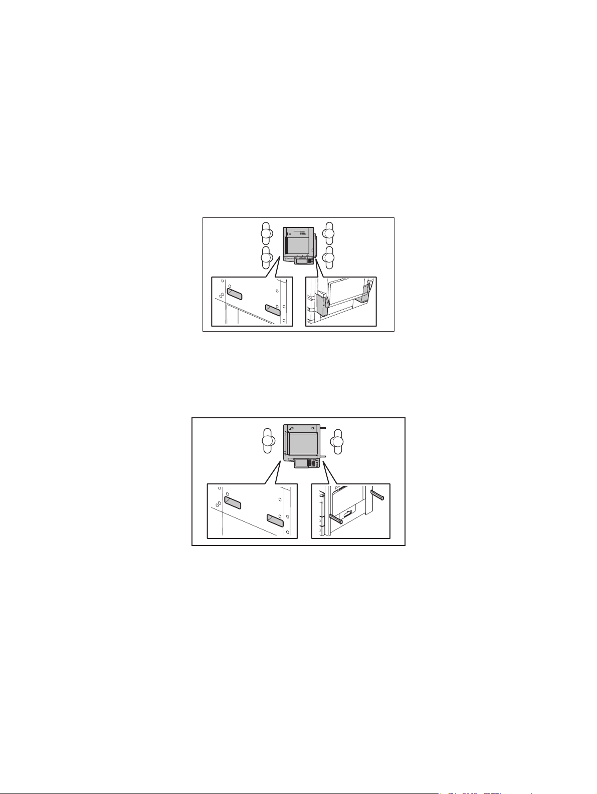
1) Transportation/Installation
- When transporting/installing the equipment, employ four persons and be sure to hold the posi-
tions as shown in the figure.
The equipment is quite heavy and weighs approximately 120 kg (264.55 lb.), therefore pay full
attention when handling it. (e-STUDIO2500c/3500c/3510c, e-STUDIO2330C/2820C/2830C/
3520C/3530C/4520C, e-STUDIO2040C/2540C/3040C/3540C/4540C)
- When transporting/installing the equipment, employ two persons and be sure to hold the posi-
tions as shown in the figure. The equipment is quite heavy, and e-STUDIO205L/255/305 weighs
approximately 57 kg (125.66lb.), and e-STUDIO355/455 weighs approximately 60 kg (132.28
lb.), therefore pay full attention when handling it. The equipment is quite heavy, and eSTUDIO206L/256/306 weighs approximately 58 kg (127.87 lb.), and e-STUDIO356/456 weighs
approximately 61 kg (134.48 lb.), therefore pay full attention when handling it.
- When transporting/installing the equipment, employ four persons and be sure to move it by the
casters while lifting the stoppers. The equipment is quite heavy and weighs approximately 245 kg
(540.12 lb), therefore pay full attention when handling it. (e-STUDIO5520C/6520C/6530C, eSTUDIO5540C/6540C/6550C)
- When transporting/installing the equipment, employ four persons and be sure to move it by the
casters while lifting the stoppers. The equipment is quite heavy and weighs approximately 202 kg
(445.33 lb), therefore pay full attention when handling it. (e-STUDIO555/655/755/855,eSTUDIO556/656/756/856 )
- Be sure not to hold the movable parts or units (e.g. the control panel, ADU or RADF) when trans-
porting the equipment.
- Be sure to use a dedicated outlet with AC 110 V / 13.2 A, 115 V or 127 V / 12 A, 220-240 V / 8 A
for its power source.
- The equipment must be grounded for safety.
11/12
Page 4

- Select a suitable place for installation. Avoid excessive heat, high humidity, dust, vibration and
direct sunlight.
- Provide proper ventilation since the equipment emits a slight amount of ozone.
- To insure adequate working space for the copying operation, keep a minimum clearance of 80
cm (32”) on the left, 80 cm (32”) on the right and 10 cm (4”) on the rear.
- The equipment shall be installed near the socket outlet and shall be accessible.
- Be sure to fix and plug in the power cable securely after the installation so that no one trips over
it.
2) General Precautions at Service
- Be sure to turn the power OFF and unplug the power cable during service (except for the service
should be done with the power turned ON).
- Unplug the power cable and clean the area around the prongs of the plug and socket outlet once
a year or more. A fire may occur when dust lies on this area.
- When the parts are disassembled, reassembly is the reverse of disassembly unless otherwise
noted in this manual or other related documents. Be careful not to install small parts such as
screws, washers, pins, E-rings, star washers, harnesses in the wrong places.
- Basically, the equipment should not be operated with any parts removed or disassembled.
- The PC board must be stored in an anti-electrostatic bag and handled carefully using a wristband
since the ICs on it may be damaged due to static electricity.
Caution: Before using the wristband, unplug the power cable of the equipment and
make sure that there are no charged objects which are not insulated in the
vicinity.
- Avoid expose to laser beam during service. This equipment uses a laser diode. Be sure not to
expose your eyes to the laser beam. Do not insert reflecting parts or tools such as a screwdriver
on the laser beam path. Remove all reflecting metals such as watches, rings, etc. before starting
service.
- Be sure not to touch high-temperature sections such as the exposure lamp, fuser unit, damp
heater and areas around them.
- Be sure not to touch high-voltage sections such as the chargers, transfer belt, 2nd transfer roller,
developer, high-voltage transformer, exposure lamp control inverter, inverter for the LCD backlight and power supply unit. Especially, the board of these components should not be touched
since the electric charge may remain in the capacitors, etc. on them even after the power is
turned OFF.
- Make sure that the equipment will not operate before touching potentially dangerous places (e.g.
rotating/operating sections such as gears, belts pulleys, fans and laser beam exit of the laser
optical unit).
- Be careful when removing the covers since there might be the parts with very sharp edges
underneath.
- When servicing the equipment with the power turned ON, be sure not to touch live sections and
rotating/operating sections. Avoid exposing your eyes to laser beam.
- Use designated jigs and tools.
- Use recommended measuring instruments or equivalents.
- Return the equipment to the original state and check the operation when the service is finished.
- Be very careful to treat the touch panel gently and never hit it. Breaking the surface could cause
malfunctions.
3) Important Service Parts for Safety
- The breaker, door switch, fuse, thermostat, thermofuse, thermistor, batteries, IC-RAMs including
lithium batteries, etc. are particularly important for safety. Be sure to handle/install them properly.
If these parts are short-circuited and their functions become ineffective, they may result in fatal
accidents such as burnout. Do not allow a short-circuit and do not use the parts not recommended by Toshiba TEC Corporation.
4) Cautionary Labels
Page 5

- During servicing, be sure to check the rating plate and cautionary labels such as “Unplug the
power cable during service”, “CAUTION. HOT”, “CAUTION. HIGH VOLTAGE”, “CAUTION.
LASER BEAM”, etc. to see if there is any dirt on their surface and if they are properly stuck to the
equipment.
5) Disposal of the Equipment, Supplies, Packing Materials, Used Batteries and IC-RAMs
- Regarding the recovery and disposal of the equipment, supplies, packing materials, used batter-
ies and IC-RAMs including lithium batteries, follow the relevant local regulations or rules.
6) When the option has been installed:
When the EFI printer board has been installed, be sure to unplug the power cable before performing
maintenance and inspection, otherwise troubles such as a communication error may occur.
Caution:
Dispose of used batteries and IC-RAMs including lithium batteries according to this manual.
Attention:
Se débarrasser de batteries et IC-RAMs usés y compris les batteries en lithium selon ce manuel.
Vorsicht:
Entsorgung der gebrauchten Batterien und IC-RAMs (inclusive der Lithium-Batterie) nach diesem Handbuch.
Page 6

Page 7

CONTENTS
GD-1210/1250/1270/116 0/1260
1. ERROR CODES ............................................................................................................1-1
1.1 Transmission/Reception Journal and Error Code List ......................................................... 1-1
1.2 Error Messages ................................................................................................................... 1-4
2. SELF-DIAGNOSIS MODE ............................................................................................ 2-1
2.1 Test Mode (03) .................................................................................................................... 2-2
2.2 Adjustment Mode (05) .........................................................................................................2-4
2.3 Setting Mode (08) ................................................................................................................ 2-6
2.4 Function Mode (13).............................................................................................................. 2-7
2.5 FAX Clearing Mode (1*)..................................................................................................... 2-61
3. TROUBLESHOOTING .................................................................................................. 3-1
3.1 Diagnosis Over Telephone .................................................................................................. 3-1
3.2 Recommend Flow Chart for Field Service ........................................................................... 3-2
3.3 Flow Chart for Recommended Telephone Screening.......................................................... 3-3
3.4 Error Analysis Flow.............................................................................................................. 3-6
3.4.1 Self-Diagnosis function............................................................................................. 3-6
3.4.2 Precautions for diagnosis ......................................................................................... 3-6
3.5 Fault Analysis ...................................................................................................................... 3-7
3.5.1 Power-ON is not possible ......................................................................................... 3-7
3.5.2 Original transport error for RADF ............................................................................. 3-7
3.5.3 Recording paper transport error ............................................................................... 3-7
3.5.4 Image trouble ........................................................................................................... 3-7
3.5.5 Communication error ................................................................................................ 3-8
3.6 Lists Required at Problem in the Field................................................................................. 3-9
3.6.1 List printing procedure .............................................................................................. 3-9
3.6.2 List printing procedure in the equipment with service UI ........................................ 3-15
3.7 Other Information Required for Error Analysis................................................................... 3-17
4. PRECAUTIONS FOR INSTALLATION OF FAX UNIT ................................................. 4-1
4.1 Installation of FAX Unit ........................................................................................................ 4-1
4.2 Country/Region Code ..........................................................................................................4-2
5. FIRMWARE UPDATING ............................................................................................... 5-1
© 2006 - 2011 TOSHIBA TEC CORPORATION All rights reserved GD-1210/1250/1270/1160/1260
1
CONTENTS
Page 8

GD-1210/1250/1270/1160/1260 © 2006 - 2011 TOSHIBA TEC CORPORATION All rights reserved
CONTENTS
2
Page 9

1. ERROR CODES
2. SELF-DIAGNOSIS MODE
3. TROUBLESHOOTING
4. PRECAUTIONS FOR INSTALLATION OF FAX
UNIT
5. FIRMWARE UPDATING
1
2
3
4
5
Page 10

Page 11
1. ERROR CODES
1.1 Transmission/Reception Journal and Error Code List
The transmission journal is shown below. The error code list and status code list are available in the following pages. The reception journal is output in the same form.
TRANSMISSION JOURNAL TIME :MM-DD-YY TIME
TEL NO.1 : XXXXXXXXX
TEL NO.2 : XXXXXXXXX
NAME : X X X X X X X
NO. FILE NO. DATE TIMED DURATION PGS TO DEPT MODE STATUS
001 001 12.01 09:00 00:55 2 ABCDG 3 xxx OK xxxx
Status code
Error code
1
Fig. 1-1
© 2006 - 2011 TOSHIBA TEC CORPORATION All rights reserved GD-1210/1250/1270/1160/1260
1 - 1
ERROR CODES
Page 12

1) Error code list
If an error has occurred during communication, an error code is indicated below “STATUS” on the
transmission/reception journal.
Take the appropriate action referring to the following list.
Error code Content Situation and corrective action
0000 Normal
0012 Original jam Remove the jamming document and retransmit it.
0013 Door is open Close the doors securely and retransmit the document.
0020 Power failure A power failure occurred during transmission or reception, and
the transmission/reception data were lost. Attempt the transmission/reception again.
0030 Stop by paper jam during the
direct transmission
0033 Polling error Polling was not performed because the polling document was
0042 Memory full The memory became full a memory abnormality occurred dur-
0050 Line is busy Transmission is not made because the line is busy. Attempt
0053 Security mismatch in relay or mail
box transmission
00B0 Initial signal not detected NSF/DIS cannot be detected. Check the receiver and attempt
00B1 Terminal constants not compati-
ble
00B2 Reception of DCN (Phase B) DCN was received in the phase B.
00B3 DCS/DTC not detected DCS/DTC cannot be detected.
00B4 Training error The sender performed fall-back but the transmission was not
00B5 CFR not detected A training signal was sent out but CFR cannot be detected.
00C0 Image signal carrier not detected A carrier was not detected on the receiving side. Adjust the
00C1 High speed signal not detected A high-speed signal was not detected on the receiving side.
00C2 Image signal carrier disconnected Carrier disconnection was detected after the image signal was
00C3 1st EOL not detected 1st EOL was not detected after the high-speed signal was
00C4 EOL not detected EOL cannot be detected on the receiving side. Or decoding is
Remove the jamming paper and transmit it.
not found or the security codes were mismatched. Check the
polling document or security code on the other side and
attempt the polling again.
ing reception. (The pages normally received are printed out.)
Check the remaining memory space or memory status, and
attempt the reception again.
the transmission again. As the number of the redialings is
increased, the possibility for successful transmission is
increased.
Check your security code and system password of the other
side as well as your own.
the transmission again.
DIS/NSF that cannot be handled by the sender was received.
The receiver received NSS/DCS other than those declared by
DIS/NSF. Check the transmission/reception functions, and
attempt the communication again.
made. After the reception of FTT, the receiver received a timeout or DCN. Adjust the transmitter attenuator, link equalizer,
etc. and retry the communication.
Adjust the transmitter attenuator, link equalizer, etc. and retry
the transmission.
transmitter attenuator, link equalizer, etc. and retry the transmission.
Adjust the transmitter attenuator, link equalizer, etc. and retry
the transmission.
detected.
detected.
not possible with MMR.
GD-1210/1250/1270/1160/1260 © 2006 - 2011 TOSHIBA TEC CORPORATION All rights reserved
ERROR CODES
1 - 2
Page 13
Error code Content Situation and corrective action
00D0 Post message not detected A post message cannot be detected. Retry the communica-
tion. MCF, RTP, RTN, PIN and PIP cannot be detected on the
sending side. MPS, EOM and EOP cannot be detected on the
receiving side.
00D1 Reception of DCN DCN was received.
00D2 Poor image quality Quality of the received image is poor. Retry the transmission.
00E8 HDD error Hardware is defective.
00F0 Software trouble Software is defective.
00F1 Hardware noise Hardware is defective.
2) Status code list
Mode Transmission speed Resolution Encoding system
0 2400 8 x 3.85 MH
1 4800 8 x 7.7 MR
2 7200 8 x 15.4 MMR
3 9600 JBIG
4 12000 16 x 15.4
5 14400
6V.34
7
8 300 x 300
9
A
B
C
D
E
F
1
[Example of the indication of a status code]
522
MMR (encoding system
8 x 15.4 (resolution
14400 (transmission speed
)
)
)
For the combination of 14400 bps, 8x15.4 and MMR, as shown above, a status of “522” is indicate.
© 2006 - 2011 TOSHIBA TEC CORPORATION All rights reserved GD-1210/1250/1270/1160/1260
1 - 3
ERROR CODES
Page 14

1.2 Error Messages
Error messages are not displayed for the background jobs (memory transmission and memory reception). See the reception/transmission report for the details of the errors.
If an original jam during the direct transmission or recording paper jam during printing occurred, error
messages are displayed like when original jam occurred in the equipment.
Error messages and corrective actions
Error Symptom Message Remarks
Memory full Communication was interrupted
Line is busy Redialing was attempted for the
Initial signal not
detected
Terminal constants
not compatible
Training error Fall-back is not made success-
CFR not detected CFR (FTT) is not detected. Communication
Image signal carrier not detected
Image signal not
detected
because the memory became full.
specified number of times but the
line is still busy.
DIS is not detected. Communication
Received DIS unable to be handled.
Received DCS which is beyond
the capability of the receiver.
fully.
Became time-out after FTT was
sent out.
Image signal carrier cannot be
detected.
High-speed signal cannot be
received by the receiver.
Memory
overflow
error
Communication
error
error
Message displayed only during
the memory input.
It is not displayed during the
memory reception.
Job information is stored in the
memory when the final retry is
finished.
EOL time-out EOL timer exceeded by 13 sec-
Post message not
detected
Poor image quality TX: Received RTN/PIN/ERR
Software overdrive WDT communication terminated
Hardware noise Communication terminated due to
GD-1210/1250/1270/1160/1260 © 2006 - 2011 TOSHIBA TEC CORPORATION All rights reserved
ERROR CODES
onds
Post message is not detected. Communication
error
Communication
RX: Transmitted RTN/PIN/ERR
due to software overdrive
software overdrive caused by
hardware noise
error
Communication
error
Communication
error
1 - 4
Page 15

2. SELF-DIAGNOSIS MODE
There are two types of the self-diagnosis mode for the FAX operation.
• Test mode (03), adjustment mode (05) and setting mode (08): Some items are added to the test
mode (03), adjustment mode (05) and setting mode (08) of the self-diagnosis function when the
optional FAX unit is installed.
• FAX function mode (13) and FAX clearing mode (1*): These two modes are newly added to the
machine when the FAX unit is installed. Started up by turning ON the power while pressing the specified keys are being pressed.
The followings are the modes which are added to (or extend) the PPC self-diagnosis function.
Mode For start Function Display
Test Mode [0]+[3]+[POWER] Output check (modem test, dialing
Adjustment Mode [0]+[5]+[POWER] Adjustment of the various items 100% A Test Mode
Setting Mode [0]+[8]+[POWER] Setting the destination 100% D Test Mode
FAX Function Mode [1]+[3]+[POWER] Setting functions of the various
FAX Clearing Mode [1]+[*]+[POWER] Initialization of the various memory
Trace List Output
Mode
Trace List Output
Mode
Digital keys on the list output
screen (without entering the
self-diagnostic mode)
Operating from the screen for
Service UI (without entering
the self-diagnostic mode)
test, CML test)
items
areas
(user registration area, system setting area, image data area)
Outputs the protocol trace list,
dump list and function setting list
Outputs the protocol trace list,
dump list and function setting list
100% C Test Mode
100% F Test Mode
100% CL Test Mode
USER FUNCTIONS
-
2
To enter the desired mode, turn the power ON while pressing two digital keys designated to each mode
(e.g. [0] and [5]) simultaneously.
Notes:
• To finish the self-diagnosis mode, make sure to turn the power OFF and then back ON.
When the equipment is started in one of the self-diagnosis modes, the equipment is occupied
by the mode until the power is turned OFF. In this case, the recovery processing for the FAX
operation is not performed.
• Faxes received automatically during the self-diagnosis mode may not be printed out. Be sure
to disconnect the modular code from the line connectors (LINE1, LINE2) of the equipment
before starting the self-diagnosis mode. Also, be sure to finish the self-diagnosis mode by
turning the power OFF and back ON before connecting the modular code.
• The trace list output mode can be used by operating from the Service UI screen for models in
which Service UI is embedded. For details of Service UI, refer to the Service Manual of the
MFP.
© 2006 - 2011 TOSHIBA TEC CORPORATION All rights reserved GD-1210/1250/1270/1160/1260
2 - 1
11/10
SELF-DIAGNOSIS MODE
Page 16
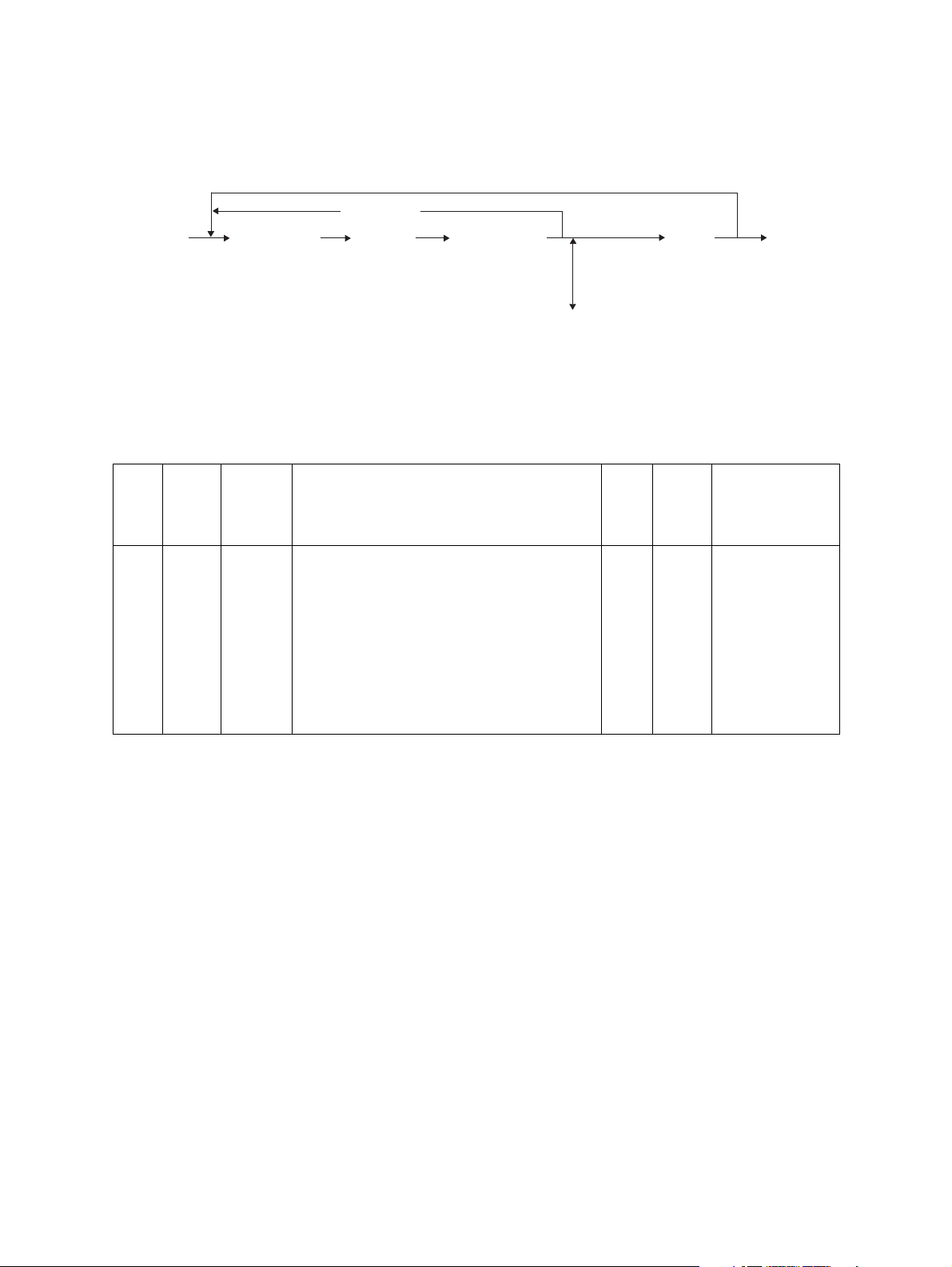
2.1 Test Mode (03)
The modem test output, dialing test output and CML test output are performed in the Test Mode (03).
1) Modem test / CML test
[Operation procedure]
[0] [3][
[
POWER
FAX
](
Switch line 1 and 2
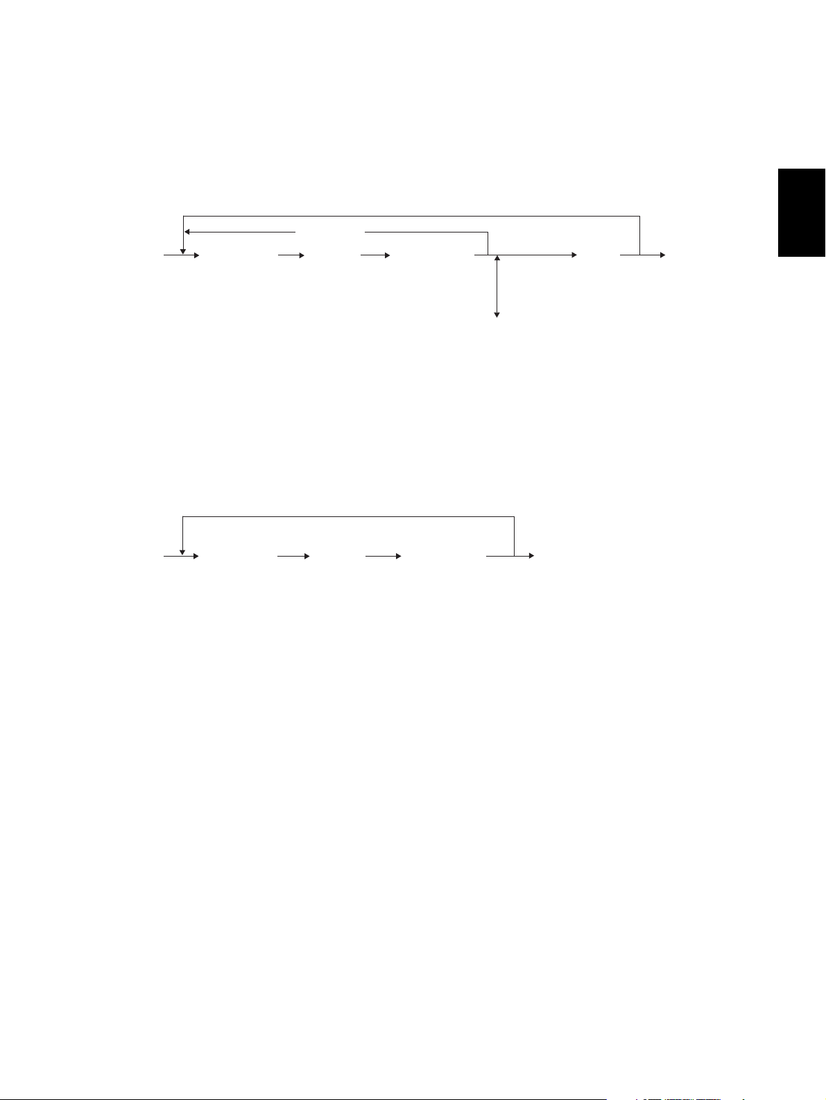
2) Dialing test
[Operation procedure]
[0] [3]
[
POWER
]
[
Digital key
(
]([
FAX
[
]
FAX
(
Switch line 1 and 2
]
)
Code
[
CLEAR
]) [
Digital key
][
START]Operation started
)(
Fig. 2-1
([
])
FAX
]
)(
Code
)
[
CLEAR
[
START
]
]
[
Digital key
[
START
Fig. 2-2
][
]
START
[
POWER] OFF
End
][
POWER] OFF
(
End
)
)
GD-1210/1250/1270/1160/1260 © 2006 - 2011 TOSHIBA TEC CORPORATION All rights reserved
SELF-DIAGNOSIS MODE
2 - 2
Page 17

Test code list
Code Element Test
03-301 FAX Modem test 2100 Hz
03-302 FAX Modem test 14.4 kbps (V.17)
03-303 FAX Modem test 9.6 kbps (V.29)
03-304 FAX Modem test 4.8 kbps (V.27)
03-305 FAX Modem test 300 BPS
03-306 FAX Modem test 1850 Hz
03-307 FAX Modem test 1650 Hz
03-308 FAX Modem test 1100 Hz
03-309 FAX Modem test 462 Hz
03-310 FAX Modem test 1300 Hz
03-311 FAX Modem test 33.6 kbps (V.34)
03-312 FAX Modem test 28.8 kbps (V.34)
03-313 FAX Modem test 24.0 kbps (V.34)
03-314 FAX Modem test 16.8 kbps (V.34)
03-315 FAX Dialing test 10 PPS (Tested with the digital keys)
(The dial number corresponding to the key which was pressed is kept outputting on the
circuit. The pressed key is displayed on the control panel.)
03-317 FAX Dialing test PB (Tested with the digital keys)
(The dial number corresponding to the key which was pressed is kept outputting on the
circuit. The pressed key is displayed on the control panel.)
03-318 FAX Modem test 12.0 kbps (V.17)
2
03-319 FAX Modem test 7.2 kbps (V.29)
03-320 FAX Modem test 2.4 kbps (V.27ter)
03-321 FAX Performs Read/Write test to all the image memories mounted on the FAX board and
displays the test result (status) on the control panel. Also, detects automatically whether
the extended memory is mounted or not.
03-322 FAX CML test: Turning ON the CML relay
© 2006 - 2011 TOSHIBA TEC CORPORATION All rights reserved GD-1210/1250/1270/1160/1260
2 - 3
11/10
SELF-DIAGNOSIS MODE
Page 18
2.2 Adjustment Mode (05)
Parameter setting for the FAX image processing is performed in the Adjustment Mode (05).
1) Setting parameters for the FAX image processing
[Operation procedure]
[0] [5][
[POWER]
Digital key
(
)
Code
][
START
][
Digital key
*[FC
(
Key in the adjustment value
[
CANCEL
][
]
[
]
)
CLEAR
(
In case the value is corrected
Fig. 2-3
INTERRUPT
(
Save the value in the RAM
]
[
ENTER
[OK] *1
or
]
[
POWER] OFF
]
)
* “-” can be entered with the [FC] button.
*1: For e-STUDIO2040C/2540C/3040C/3540C/4540C, e-STUDIO5540C/6540C/6550C, eSTUDIO206L/256/306/356/456 and e-STUDIO556/656/756/856.
)
GD-1210/1250/1270/1160/1260 © 2006 - 2011 TOSHIBA TEC CORPORATION All rights reserved
SELF-DIAGNOSIS MODE
2 - 4
11/12
Page 19

Adjustment codes for the image processing parameters
05-
05-
Code
*1
057534
Element Adjustment item Mode
Density Adjustment of the threshold value for the
binarization
Center value
Density Adjustment of the threshold value for the
binarization
Lighter step value
Code
700
701
Image
quality
mode
Default
Accept-
able
value
FAX Text 125 0 to 255
FAX Text 20 0 to 255
2
05-
702
Density Adjustment of the threshold value for the
binarization
FAX Text 20 0 to 255
Darker step value
05-
710
05-
714
05-
715
05-
719
05-
720
05-
724
05-
725
05-
729
057535
057533
057543
057542
Density Manual-density fine adjustment
Error diffusion, Center value
Density Manual-density fine adjustment
Error diffusion, Center value
Density Manual-density fine adjustment
Error diffusion, Lighter step value
Density Manual-density fine adjustment
Error diffusion, Lighter step value
Density Manual-density fine adjustment
Error diffusion, Darker step value
Density Manual-density fine adjustment
Error diffusion, Darker step value
Density Auto-density fine adjustment
Error diffusion
Density Auto-density fine adjustment
Error diffusion
FAX Photo 128 0 to 255
FAX Text /
128 0 to 255
Photo
FAX Photo 20 0 to 255
FAX Text /
20 0 to 255
Photo
FAX Photo 20 0 to 255
FAX Text /
20 0 to 255
Photo
FAX Photo 128 0 to 255
FAX Text /
128 0 to 255
Photo
*1: For e-STUDIO2040C/2540C/3040C/3540C/4540C, e-STUDIO5540C/6540C/6550C, eSTUDIO206L/256/306/356/456 and e-STUDIO556/656/756/856.
© 2006 - 2011 TOSHIBA TEC CORPORATION All rights reserved GD-1210/1250/1270/1160/1260
2 - 5
11/12
SELF-DIAGNOSIS MODE
Page 20
2.3 Setting Mode (08)
The destination is set in the Setting Mode (08).
[Operation procedure]
[0] [8]
[
POWER
]
Digital key
(
)
Code
[
CANCEL
][
START
]
][
Digital key
(
Key in a value
(
In case the value is corrected
Fig. 2-4
]
)
[
CLEAR
[
ENTER
]
or
[
INTERRUPT
]
[OK] *1
(
Save the value in the RAM
]
)
*1: For e-STUDIO2040C/2540C/3040C/3540C/4540C, e-STUDIO5540C/6540C/6550C, eSTUDIO206L/256/306/356/456 and e-STUDIO556/656/756/856.
Default value at
Code
08-
701
Code
*1
08-
9001
Element Adjustment item Mode
Destination
1: Asia 2: Australia 3: Hong Kong
4: U.S.A/Canada 5: Germany
6: Great Britain 7: Italy 8: Belgium
9: Holland 10: Finland 11: Spain
FAX
12: Austria 13: Switzerland
14: Sweden 15: Denmark
16: Norway 17: Portugal 18: France
19: Greece 20: Poland 21: Hungary
22: Czech Rep. 23: Turkey
24: South Africa 25: Taiwan
Image
mode
FAX -
product ship-
NA: 4
TW: 25
EU: 5
AU: 2
AS: 1
C: 1
[
POWER
OFF
)
the
ment
][
*1: For e-STUDIO2040C/2540C/3040C/3540C/4540C, e-STUDIO5540C/6540C/6550C, eSTUDIO206L/256/306/356/456 and e-STUDIO556/656/756/856.
GD-1210/1250/1270/1160/1260 © 2006 - 2011 TOSHIBA TEC CORPORATION All rights reserved
SELF-DIAGNOSIS MODE
2 - 6
11/12
Page 21
2.4 Function Mode (13)
Various functions are set in the Function Mode (13).
1) Procedure to set the functions
Key in a code and change the set value.
[Operation procedure]
[
CANCEL
[1] [3]
[
POWER
]
[
Digital key
(
Code
][
)
START
*1: For e-STUDIO2040C/2540C/3040C/3540C/4540C, e-STUDIO5540C/6540C/6550C, eSTUDIO206L/256/306/356/456 and e-STUDIO556/656/756/856.
2) Procedure to confirm the set value
]
][
Digital key
(
Key in a value
(
In case the value is corrected
Fig. 2-5
]
)
[
CLEAR
[
ENTER
or
[
INTERRUPT
[OK] *1
(
Save the value in the RAM
]
)
2
]
]
[
POWER
)
]
OFF
[Operation procedure]
[1] [3]
[
POWER
]
[
Digital key
(
Code
][
)
[
ENTER
[
INTERRUPT
START
]
[OK] *1
(
Set value cannot be changed
Fig. 2-6
]
[
POWER] OFFor
]
)
*1: For e-STUDIO2040C/2540C/3040C/3540C/4540C, e-STUDIO5540C/6540C/6550C, eSTUDIO206L/256/306/356/456 and e-STUDIO556/656/756/856.
© 2006 - 2011 TOSHIBA TEC CORPORATION All rights reserved GD-1210/1250/1270/1160/1260
2 - 7
11/12
SELF-DIAGNOSIS MODE
Page 22

Function code list (100-999)
100-299 Adjustment within the dialing standards
13-
13-
13-
13-
13-
13-
13-
13-
Adjust-
ment
DTC frequency
(PSTN)
(Line 1)
DTC
time
(PSTN)
(Line 1)
LCC
allowed
gaps
(PSTN)
(Line 1)
DTC
allowed
gaps
(PSTN)
(Line 1)
DTC/
LCC for
PSTN
(Line 1)
DTC
time out
(PSTN)
(Line 1)
DTC frequency
(PABX)
(Line 1)
DTC
time
(PABX)
(Line 1)
Function Setting
Sets the dial
tone frequency
to be detected
for the PSTN.
0: 300-600 Hz
1: 300-650 Hz
2: 390-550 Hz
3: 400-450 Hz
4: 350-480 Hz
5: 300-500 Hz
Sets the time
for a tone
sounds to be
determined as
dial tone for the
PSTN.
0: 2 sec
1: 800 ms
2: 400 ms
3: 1 sec
4: 1.3 sec
5: 1.8 sec
6: 2.5 sec
7: 500 ms
Sets the interruption time for
the PSTN to be
ignored during
0: OFF
1: 50 ms
2: 100 ms
3: 200 ms
LCC.
Sets the interruption time for
PSTN to be
ignored during
0: OFF
1: 320 ms
2: 160 ms
3: 240 ms
DTC.
Selects which is
0: BZT
to be used for
the PSTN, DTC
or LCC.
1: LCC 5 sec
2: DTC only
3: FRN
4: DTC (JPN)
5: NO
Sets how long
the dial tone
detection is performed.
0: 20 sec
1: 10 sec
2: 8 sec
3: 15 sec
4: 3.3 sec
Sets the dial
tone frequency
to be detected
for PABX.
0: 300-600 Hz
1: 300-650 Hz
2: 390-550 Hz
3: 400-450 Hz
4: 350-480 Hz
5: 300-500 Hz
Sets the time
for a tone
sounds to be
determined as
dial tone for the
PAB X.
0: 2 sec
1: 800 ms
2: 400 ms
3: 1 sec
4: 1.3 sec
5: 1.8 sec
6: 2.5 sec
7: 150 ms
(DTC/LCC)
(DTC/LCC)
DTC&LCC
Code
100
101
102
103
104
105
106
107
Default
ASM AUS HKG USA DEU GBR ITA BEL NDL
000011111
000322222
000322222
111111111
222222222
000111111
000011111
000622222
GD-1210/1250/1270/1160/1260 © 2006 - 2011 TOSHIBA TEC CORPORATION All rights reserved
SELF-DIAGNOSIS MODE
2 - 8
11/10
Page 23

Default
FIN ESP AUT CHE SWE DNK NOR PRT FRA GRC POL HUN CZE TUR ZAF TWN
Code
11111 1111111100113-
100
22222 2222222200213-
101
22222 2222222200213-
102
2
11111 1111111111113-
103
22222 2222222222213-
104
11111 1111111100113-
105
11111 1111111100113-
106
22222 2222222200213-
107
© 2006 - 2011 TOSHIBA TEC CORPORATION All rights reserved GD-1210/1250/1270/1160/1260
2 - 9
11/10
SELF-DIAGNOSIS MODE
Page 24

Code
13-
108
13-
109
13-
110
13-
111
13-
112
13-
116
13-
117
13-
122
Adjust-
ment
LCC
allowed
gaps
(PABX)
(Line 1)
DTC
allowed
gaps
(PABX)
(Line 1)
DTC/
LCC for
PABX
(Line 1)
DTC
time out
(PABX)
(Line 1)
BTC frequency
(Line 1)
Dial T1
timer
(Line 1)
Dial stop
after T1
CML
make
time
before
dialing
Function Setting
Sets the interruption time for
the PABX to be
ignored during
0: OFF
1: 50 ms
2: 100 ms
3: 200 ms
LCC.
Sets the interruption time for
the PABX to be
ignored during
0: OFF
1: 320 ms
2: 160 ms
3: 240 ms
DTC.
Selects which is
0: BZT
to be used for
the PABX, DTC
or LCC.
1: LCC 5 sec
2: DTC only
3: FRN
4: DTC (JPN)
5: NO
Sets how long
the dial tone
detection is performed.
0: 20 sec
1: 10 sec
2: 8 sec
3: 15 sec
4: 3.3 sec
Sets the busy
0: Not
tone frequency
to be detected
for the PSTN
and PABX.
1: 300-600 Hz
2: 350-550 Hz
3: 300-500 Hz
4: 300-700 Hz
Sets the time to
wait for a
response from
the receiver
after dialing is
0: 60 sec
1: 35 sec
2: 90 sec
3: 55 sec
4: 115 sec
completed.
In case of T1
time-out (no
0: OFF
1: ON
response from
the receiver)
during the automatic dialing,
redialing is not
performed and
it is determined
that the transmission is terminated due to
error.
Pause before
dialing
0: 0 ms
1: 10 ms
¦
255:2550 ms
Default
ASM AUS HKG USA DEU GBR ITA BEL NDL
000033333
111111111
555555555
(DTC/LCC)
(DTC/LCC)
DTC&LCC
000111111
000111111
detected
030322222
000100000
222222222
GD-1210/1250/1270/1160/1260 © 2006 - 2011 TOSHIBA TEC CORPORATION All rights reserved
SELF-DIAGNOSIS MODE
2 - 10
11/10
Page 25

Default
FIN ESP AUT CHE SWE DNK NOR PRT FRA GRC POL HUN CZE TUR ZAF TWN
Code
33333 3333333300213-
108
11111 1111111111113-
109
55555 5555555555513-
110
11111 1111111100113-
111
11111 1111111100113-
112
22222 2222222200313-
116
2
00000 0000000000013-
117
22222 2222222222213-
122
© 2006 - 2011 TOSHIBA TEC CORPORATION All rights reserved GD-1210/1250/1270/1160/1260
2 - 11
11/10
SELF-DIAGNOSIS MODE
Page 26

Code
13-
123
13-
125
13-
127
13-
128
13-
129
13-
132
13-
135
Adjust-
ment
CML
hold
time
after
dialing
Dial
information
(Line 1)
Internal
retry
Redialing
counter
Time for
a pause
(Line 1)
Interdigit
pause
(Line 1)
Redialing interval
(Line 1)
Function Setting
Pause after
dialing
0: 0 ms
1: 10 ms
¦
255:2550 ms
Sets the definition of the DP
dial.
0: Normal
1: Shift
2: Reverse
Normal: n
Shift: n+1
Reverse: 10-n
n=Dial No.
When dialing is
interrupted
0: OFF
1: ON
because any of
the settings for
DTC/LCC is not
satisfied during
redialing, that
redialing is
ignored since it
is considered
as an internal
retry.
Sets the number of redialings.
0: No retry
1: 1 redialing
¦
14: 14 redial-
Sets the time
for a pause
when it is
inserted
between the
dial numbers.
Sets the interval
between digits
for DP dialing.
0: 0 sec
1: 1 sec
2: 2 sec
3: 4 sec
4: 3.3 sec
5: 10 sec
0: 900 ms
1: 550 ms
2: 700 ms
3: 800 ms
Sets the interval
0: Default
between redialings.
1: 1 min
¦
15: 15 min
Default
ASM AUS HKG USA DEU GBR ITA BEL NDL
100 100 100 100 100 100 100 100 100
000000000
000011000
524534335
ings
422422320
002303322
313100322
(3 min)
GD-1210/1250/1270/1160/1260 © 2006 - 2011 TOSHIBA TEC CORPORATION All rights reserved
SELF-DIAGNOSIS MODE
2 - 12
11/10
Page 27

Default
FIN ESP AUT CHE SWE DNK NOR PRT FRA GRC POL HUN CZE TUR ZAF TWN
Code
100 100 100 100 100 100 100 100 100 100 100 100 100 100 100 100 13-
123
00001 0200000000013-
125
00100 1100000000013-
127
33145 4935433355213-
128
22202 2212444444413-
129
2
01332 2220330000013-
132
02221 0013333333213-
135
© 2006 - 2011 TOSHIBA TEC CORPORATION All rights reserved GD-1210/1250/1270/1160/1260
2 - 13
11/10
SELF-DIAGNOSIS MODE
Page 28

Code
13-
137
13-
138
13-
139
13-
140
13-
141
Adjust-
ment
DP
make/
break
ratio
(Line 1)
MF timing
(Line 1)
DTC RX
ATT
(PSTN)
(Line 1)
DTC RX
ATT
(PABX)
(Line 1)
MF TXATT
(Line 1)
Function Setting
Sets the make/
0: 60/40
break ratio for
DP dialing.
1: 67/33
2: 63/37
3: 50/50
4: 67/33
5: 70/30
(20 PPS, TWN
only)
Sets the ON/
OFF timing of
MF signals. Do
not set the
value “4” for the
function code
138 and 268 to
0: 80/80 ms
1: 70/70 ms
2: 70/150 ms
3: 60/60 ms
4: 80/100 ms
5: 150/50 ms
6: 150/240 ms
ensure minimum time of the
MF signal duration ruled in
TBR21
(Requirement
4.8.2.4, 4.8.2.5)
Sets the reception level when
the dial tone is
detected for the
PSTN.
0: -24 dBm
1: -27 dBm
2: -30 dBm
3: -33 dBm
4: -36 dBm
5: -39 dBm
6: -42 dBm
7: -45 dBm
Sets the reception level when
the dial tone is
detected for the
PABX.
0: -24 dBm
1: -27 dBm
2: -30 dBm
3: -33 dBm
4: -36 dBm
5: -39 dBm
6: -42 dBm
7: -45 dBm
Sets the attenuator value for
the MF signal.
0: 0 dB
1: -1 dB
¦
15: -15 dB
(Value
decreased one
by one)
Default
ASM AUS HKG USA DEU GBR ITA BEL NDL
111001010
(10 PPS)
(10 PPS)
(10 PPS)
(10 PPS)
(20 PPS)
202440011
666666666
666666666
385355555
GD-1210/1250/1270/1160/1260 © 2006 - 2011 TOSHIBA TEC CORPORATION All rights reserved
SELF-DIAGNOSIS MODE
2 - 14
11/10
Page 29

Default
FIN ESP AUT CHE SWE DNK NOR PRT FRA GRC POL HUN CZE TUR ZAF TWN
Code
01000 1011010011513-
137
2
02001 2000403122413-
138
66666 6666666666613-
139
66666 6666666666613-
140
55555 5555555533313-
141
© 2006 - 2011 TOSHIBA TEC CORPORATION All rights reserved GD-1210/1250/1270/1160/1260
2 - 15
11/10
SELF-DIAGNOSIS MODE
Page 30

Code
13-
142
13-
143
13-
149
13-
150
13-
151
Adjust-
ment
International
DTC frequency
International
dial
access
code
(Line 1)
ATT
control
(Line 1)
BTC ON
time
(Line 1)
BTC
OFF
time
(Line 1)
Function Setting
Selects the fre-
00: No detecquency range
for the dial
tone of the first
pause to be
detected.
01: 300-600 Hz
02: 300-650 Hz
03: 390-550 Hz
04: 400-450 Hz
05: 350-480 Hz
06: 300-500 Hz
07: France
Selects the fre-
10: No detecquency range
for the dial
tone to be
detected after
dialing the second international dial
access code.
Sets the international
access code.
11: 300-600 Hz
12: 30-650 Hz
13: 390-550 Hz
14: 400-450 Hz
15: 350-480 Hz
16: 300-500 Hz
17: France
Numeric value
of 3 digits
(Default set-
ting: 4 digits)
Sets the
receiver atten-
0: OFF
1: -3 dB
uator.
Sets time that
a busy-tone
0: 80-650 ms
1: 450-550
signal is output to be deter-
2: 200-650
mined it is ON.
3: 400-600
4: 120-550
5: 420-610
Sets time that
a busy-tone
0: 80-650 ms
1: 450-550
signal is not
output to be
2: 200-650
determined it is
OFF.
3: 400-600
4: 160-600
5: 170-700
6: 380-630
7: 150-470
Default
ASM AUS HKG USA DEU GBR ITA BEL NDL
000000000
tion
Dual Tone
(not used)
tion
Dual Tone
(not used)
1000 1000 1000 1000 1000 1000 1000 1000 1000
000000000
222222222
ms
ms
ms
ms
ms
222222222
ms
ms
ms
ms
ms
ms
ms
GD-1210/1250/1270/1160/1260 © 2006 - 2011 TOSHIBA TEC CORPORATION All rights reserved
SELF-DIAGNOSIS MODE
2 - 16
11/10
Page 31

Default
FIN ESP AUT CHE SWE DNK NOR PRT FRA GRC POL HUN CZE TUR ZAF TWN
Code
000000000000000213-
142
1000 1000 1000 1000 1000 1000 1000 1000 1000 1000 1000 1000 1000 1000 1000 1000 13-
143
2
000000000000000013-
149
222222222222222213-
150
222222222222222213-
151
© 2006 - 2011 TOSHIBA TEC CORPORATION All rights reserved GD-1210/1250/1270/1160/1260
2 - 17
11/10
SELF-DIAGNOSIS MODE
Page 32

Code
13-
152
13-
153
13-
200
13-
201
13-
203
13-
206
13-
210
13-
211
13-
213
Adjust-
ment
MF dial
level
balance
(Line 1)
Italian
Intermittent
DTC
function
(Line 1)
Exchang
e type
(Line 1)
Dial
selection
(Line 1)
Dialer
type
(Line 1)
Local/
distant
dial
(Line 1)
Exchang
e type
(Line 2)
Dial
selection
(Line 2)
Dialer
type
(Line 2)
Function Setting
Sets the difference between
the high output
and low output
of the MF signal.
0: 0 dB
1: -1 dB
¦
4: -4 dB
(Value
decreased
one by one)
Sets Italian
intermittent
0: OFF
1: ON
DTC function.
Selects the
exchange type.
Selects the
0: PSTN
1: PABX
0: Not
access type for
the PABX.
1: Local/Dis-
2: Access
Selects the dial
type.
Key in an
access code
designated for
the access type
0: DP
1: MF
Numeric value
of 3 digits (4
digits for the
default setting)
selected for the
function code
201.
Local: 2 digits
Distant: 2 digits
Access Digit: 3
digits
Selects the
exchange type.
Selects the
0: PSTN
1: PABX
0: Not
access type for
the PABX.
1: Local/Dis-
2: Access
Selects the dial
type.
0: DP
1: MF
Default
ASM AUS HKG USA DEU GBR ITA BEL NDL
222222222
000000100
000000000
111111111
defined
tant
Digit
111111111
1000 1000 1000 1000 1000 1000 1000 100 1000
000000000
111111111
defined
tant
Digit
111111111
GD-1210/1250/1270/1160/1260 © 2006 - 2011 TOSHIBA TEC CORPORATION All rights reserved
SELF-DIAGNOSIS MODE
2 - 18
11/10
Page 33

Default
FIN ESP AUT CHE SWE DNK NOR PRT FRA GRC POL HUN CZE TUR ZAF TWN
Cod
e
222222222222222213-
152
2
000000000000000013-
153
000000000000000013-
200
111111111111111113-
201
111111111111111113-
203
1000 1000 1000 1000 1000 1000 1000 1000 1000 1000 1000 1000 1000 1000 1000 1000 13-
206
000000000000000013-
210
111111111111111113-
211
111111111111111113-
213
© 2006 - 2011 TOSHIBA TEC CORPORATION All rights reserved GD-1210/1250/1270/1160/1260
2 - 19
11/10
SELF-DIAGNOSIS MODE
Page 34

Code
13-
216
13-
220
13-
221
13-
222
13-
223
13-
224
13-
225
Adjust-
ment
Local/
distant
dial
(Line 2)
DTC frequency
(PSTN)
(Line 2)
DTC
time
(PSTN)
(Line 2)
LCC
allowed
gaps
(PSTN)
(Line 2)
DTC
allowed
gaps
(PSTN)
(Line 2)
DTC/
LCC for
PSTN
(Line 2)
DTC
time out
(PSTN)
(Line 2)
Function Setting
Key in an
access code
designated for
the access type
Numeric value
of 3 digits (4
digits for the
default setting)
selected for the
function code
211.
Local: 2 digits
Distant: 2 digits
Access Digit: 3
digits
Sets the dial
tone frequency
to be detected
for the PSTN.
0: 300-600 Hz
1: 300-650 Hz
2: 390-550 Hz
3: 400-450 Hz
4: 350-480 Hz
5: 300-500 Hz
Sets the time
for a tone
sounds to be
determined as
dial tone for the
PSTN.
0: 2 sec
1: 800 ms
2: 400 ms
3: 1 sec
4: 1.3 sec
5: 1.8 sec
6: 2.5 sec
7: 500 ms
Sets the interruption time for
the PSTN to be
ignored during
0: OFF
1: 50 ms
2: 100 ms
3: 200 ms
LCC.
Sets the interruption time for
the PSTN to be
ignored during
0: OFF
1: 320 ms
2: 160 ms
3: 240 ms
DTC.
Selects which is
0: BZT (DTC/
to be used for
the PSTN, DTC
or LCC.
1: LCC 5 sec
2: DTC only
3: FRN (LCC/
4: DTC (JPN&
5: NO
Sets how long
the dial tone
detection is performed.
0: 20 sec
1: 10 sec
2: 8 sec
3: 15 sec
4: 3.3 sec
Default
ASM AUS HKG USA DEU GBR ITA BEL NDL
1000 1000 1000 1000 1000 1000 1000 1000 1000
000011111
000322222
000322222
111111111
222222222
LCC)
DTC)
USA)
DTC&LCC
000111111
GD-1210/1250/1270/1160/1260 © 2006 - 2011 TOSHIBA TEC CORPORATION All rights reserved
SELF-DIAGNOSIS MODE
2 - 20
11/10
Page 35

Default
FIN ESP AUT CHE SWE DNK NOR PRT FRA GRC POL HUN CZE TUR ZAF TWN
Code
1000 1000 1000 1000 1000 1000 1000 1000 1000 1000 1000 1000 1000 1000 1000 1000 13-
216
111111111111100113-
220
2
222222222222200213-
221
222222222222200213-
222
111111111111111113-
223
222222222222222213-
224
111111111111100113-
225
© 2006 - 2011 TOSHIBA TEC CORPORATION All rights reserved GD-1210/1250/1270/1160/1260
2 - 21
11/10
SELF-DIAGNOSIS MODE
Page 36

Code
13-
226
13-
227
13-
228
13-
229
13-
230
13-
231
13-
232
13-
236
Adjust-
ment
DTC frequency
(PABX)
(Line 2)
DTC
time
(PABX)
(Line 2)
LCC
allowed
gaps
(PABX)
(Line 2)
DTC
allowed
gaps
(PABX)
(Line 2)
DTC/
LCC for
PABX
(Line 2)
DTC
time out
(PABX)
(Line 2)
BTC frequency
(Line 2)
Dial T1
timer
(Line 2)
Function Setting
Sets the dial
tone frequency
to be detected
for the PABX.
0: 300-600 Hz
1: 300-650 Hz
2: 390-550 Hz
3: 400-450 Hz
4: 350-480 Hz
5: 300-500 Hz
Sets the time
for a tone
sounds to be
determined as
dial tone for the
PABX.
0: 2 sec
1: 800 ms
2: 400 ms
3: 1 sec
4: 1.3 sec
5: 1.8 sec
6: 2.5 sec
7: 150 ms
Sets the interruption time for
the PABX to be
ignored during
0: OFF
1: 50 ms
2: 100 ms
3: 200 ms
LCC.
Sets the interruption time for
the PABX to be
ignored during
0: OFF
1: 320 ms
2: 160 ms
3: 240 ms
DTC.
Selects which is
0: BZT (DTC/
to be used for
the PABX, DTC
or LCC.
1: LCC 5 sec
2: DTC only
3: FRN (LCC/
4: DTC (JPN&
5: NO
Sets how long
the dial tone
detection is performed.
0: 20 sec
1: 10 sec
2: 8 sec
3: 15 sec
4: 3.3 sec
Sets the busy
0: Not
tone frequency
to be detected
for the PSTN
and PABX.
1: 300-600 Hz
2: 350-550 Hz
3: 300-500 Hz
4: 300-700 Hz
Sets the time to
wait for a
response from
the receiver
after dialing is
0: 60 sec
1: 35 sec
2: 90 sec
3: 55 sec
4: 115 sec
completed.
Default
ASM AUS HKG USA DEU GBR ITA BEL NDL
000011111
000622222
000033333
111111111
555555555
LCC)
DTC)
USA)
DTC&LCC
000111111
000111111
detected
030322222
GD-1210/1250/1270/1160/1260 © 2006 - 2011 TOSHIBA TEC CORPORATION All rights reserved
SELF-DIAGNOSIS MODE
2 - 22
11/10
Page 37

Default
FIN ESP AUT CHE SWE DNK NOR PRT FRA GRC POL HUN CZE TUR ZAF TWN
Cod
e
11111 1111111100113-
226
22222 2222222200213-
227
2
33333 3333333300213-
228
11111 1111111111113-
229
55555 5555555555513-
230
11111 1111111100113-
231
11111 1111111100113-
232
22222 2222222200313-
236
© 2006 - 2011 TOSHIBA TEC CORPORATION All rights reserved GD-1210/1250/1270/1160/1260
2 - 23
11/10
SELF-DIAGNOSIS MODE
Page 38

Code
13-
245
13-
247
13-
249
13-
262
13-
267
13-
268
Adjust-
ment
Dial
information
(Line 2)
Internal
retry
(Line 2)
Time for
a pause
(Line 2)
Interdigit
pause
(Line 2)
DP
make/
break
ratio
(Line 2)
MF timing
(Line 2)
Function Setting
Sets the definition of the DP
dial.
0: Normal
1: Shift
2: Reverse
Normal: n
Shift: n+1
Reverse: 10-n
n=Dial No.
When dialing is
interrupted
0: OFF
1: ON
because any of
the settings for
DTC/LCC is not
satisfied during
redialing, that
redialing is
ignored since it
is considered
as an internal
retry.
Sets the time
for a pause
when it is
inserted
between the
dial numbers.
Sets the interval
between digits
for DP dialing.
0: 0 sec
1: 1 sec
2: 2 sec
3: 4 sec
4: 3.3 sec
5: 10 sec
0: 900 ms
1: 550 ms
2: 700 ms
3: 800 ms
Sets the make/
0: 60/40(10
break ratio for
DP dialing.
1: 67/33(10
2: 63/37(10
3: 50/50(10
4: 67/33(20
5: 70/30
(10 PPS, TWN
only)
Sets the ON/
OFF timing of
MF signals. Do
not set the
value “4” for the
function code
138 and 268 to
0: 80/80 ms
1: 70/70 ms
2: 70/150 ms
3: 60/60 ms
4: 80/100 ms
5: 150/50 ms
6: 150/240 ms
ensure minimum time of the
MF signal duration ruled in
TBR21.
(Requirement
4.8.2.4, 4.8.2.5)
Default
ASM AUS HKG USA DEU GBR ITA BEL NDL
000000000
000011000
422422320
002303322
111001010
PPS)
PPS)
PPS)
PPS)
PPS)
202440011
GD-1210/1250/1270/1160/1260 © 2006 - 2011 TOSHIBA TEC CORPORATION All rights reserved
SELF-DIAGNOSIS MODE
2 - 24
11/10
Page 39

Default
FIN ESP AUT CHE SWE DNK NOR PRT FRA GRC POL HUN CZE TUR ZAF TWN
Code
00001 0200000000013-
245
2
00100 1100000000013-
247
22202 2212444444413-
249
01332 2220330000013-
262
01000 1011010011513-
267
02001 2000403122413-
268
© 2006 - 2011 TOSHIBA TEC CORPORATION All rights reserved GD-1210/1250/1270/1160/1260
2 - 25
11/10
SELF-DIAGNOSIS MODE
Page 40

Code
13-
269
13-
270
13-
271
13-
272
13-
273
13-
279
Adjust-
ment
DTC RX
ATT
(PSTN)
(Line 2)
DTC RX
ATT
(PABX)
(Line 2)
MF TXATT
(Line 2)
International
DTC frequency
(Line 2)
International
dial
access
code
(Line 2)
ATT
control
(Line 2)
Function Setting
Sets the
reception
level when
the dial tone
is detected
for the
PSTN.
0: -24 dB
1: -27 dB
2: -30 dB
3: -33 dB
4: -36 dB
5: -39 dB
6: -42 dB
7: -45 dB
Sets the
reception
level when
the dial tone
is detected
for the
PABX.
0: -24 dB
1: -27 dB
2: -30 dB
3: -33 dB
4: -36 dB
5: -39 dB
6: -42 dB
7: -45 dB
Sets the
attenuator
value for the
MF signal.
0: 0 dB
1: -1 dB
¦
15: -15 dB
(Value
decreased one
by one)
Selects the
frequency
range for
the dial tone
of the first
pause to be
detected.
00: No detec-
tion
01: 300-600 Hz
02: 300-650 Hz
03: 390-550 Hz
04: 400-450 Hz
05: 350-480 Hz
06: 300-500 Hz
07: France
Dual Tone
(not used)
Selects the
frequency
range for
the dial tone
to be
detected
after dialing
the second
international dial
access
10: No detec-
tion
11: 300-600 Hz
12: 300-650 Hz
13: 390-550 Hz
14: 400-450 Hz
15: 350-480 Hz
16: 300-500 Hz
17: France
Dual Tone
(not used)
code.
Sets the
international
access
Numeric value
of 3 digits
(Default setting: 4 digits)
code.
Sets for the
receiver
0: OFF
1: -3 dB
attenuator.
Default
ASM AUS HKG USA DEU GBR ITA BEL NDL
666666666
666666666
385355555
000000000
1000 1000 1000 1000 1000 1000 1000 1000 1000
000000000
GD-1210/1250/1270/1160/1260 © 2006 - 2011 TOSHIBA TEC CORPORATION All rights reserved
SELF-DIAGNOSIS MODE
2 - 26
11/10
Page 41

Default
FIN ESP AUT CHE SWE DNK NOR PRT FRA GRC POL HUN CZE TUR ZAF TWN
Co
de
666 666666666666613-
269
666 666666666666613-
270
555 555555555533313-
271
000 000000000000213-
272
2
1000 1000 1000 1000 1000 1000 1000 1000 1000 1000 1000 1000 1000 1000 1000 1000 13-
273
000 000000000000013-
279
© 2006 - 2011 TOSHIBA TEC CORPORATION All rights reserved GD-1210/1250/1270/1160/1260
2 - 27
11/10
SELF-DIAGNOSIS MODE
Page 42

Code
13-
280
13-
281
13-
282
13-
283
Adjust-
ment
BTC ON
time
(Line 2)
BTC
OFF
time
(Line 2)
MF dial
level
balance
(Line 2)
Italian
intermittent
DTC
function
(Line 2)
Function Setting
Sets the time
range for the
0: 80-650 ms
1: 450-550
busy tone ontime.
2: 200-650
3: 400-600
4: 120-550
5: 420-610
Sets the time
range for the
0: 80-650 ms
1: 450-550
busy tone offtime.
2: 200-650
3: 400-600
4: 160-600
5: 170-700
6: 380-630
7: 150-470
Sets the difference between
the high output
and low output
of the MF signal.
0: 0 dB
1: -1 dB
¦
4: -4 dB
(Value
decreased one
by one)
Sets Italian
intermittent
0: OFF
1: ON
DTC function.
Default
ASM AUS HKG USA DEU GBR ITA BEL NDL
222222222
ms
ms
ms
ms
ms
222222222
ms
ms
ms
ms
ms
ms
ms
222222222
000000100
GD-1210/1250/1270/1160/1260 © 2006 - 2011 TOSHIBA TEC CORPORATION All rights reserved
SELF-DIAGNOSIS MODE
2 - 28
11/10
Page 43

Default
FIN ESP AUT CHE SWE DNK NOR PRT FRA GRC POL HUN CZE TUR ZAF TWN
Code
22222 2222222222213-
280
22222 2222222222213-
281
2
22222 2222222222213-
282
00000 0000000000013-
283
© 2006 - 2011 TOSHIBA TEC CORPORATION All rights reserved GD-1210/1250/1270/1160/1260
2 - 29
11/10
SELF-DIAGNOSIS MODE
Page 44

300-699 Adjustments for switching function specifications
13-
13-
13-
13-
13-
Adjust-
ment
CI history hold
time
(Line 1)
CI
detection frequency
range
(Line 1)
Handling of
negative
answer
TX
attenuation
value
(V.17)
(Line 1)
Cable
equalizer
(V.17)
(Line 1)
Function Setting
Sets the time
for the CI history to remain.
Sets the frequency range
for CI detection.
0: 5 sec
1: 8 sec
2: 14 sec
0: 12-80 Hz
1: 16-55 Hz
2: 20-55 Hz
3: 22-55 Hz
4: 5-200 Hz
Sets whether
the RTN
0: Abnormal
1: Normal
received is handled as abnormal (NG) or
normal when
the data are
slightly abnormal.
Abnormal: DCN
is transmitted to
stop the communication.
Normal:
Next page is
transmitted normally.
Sets the
modem transmission level for
communication
other than V.34.
0: 0 dB
1: -1 dB
¦
15: -15 dB
(Value
The smaller the
value is, the
higher the
transmission
level becomes.
If errors occur
frequently or
training is not
sent, the transmission level
should be
changed.
Sets the equalizer value which
has frequency
characteristics.
0: 0 dB
1: -4 dB
2: -8 dB
3: -12 dB
For the longdistance communication, it is
recommended
to set a large
value.
ASM AUS HKG USA DEU GBR ITA BEL NDL
111222222
000011111
111000000
10 10 10 10 12 12 12 12 12
decreased
one by
one)
000000000
Code
312
313
317
325
328
Default
GD-1210/1250/1270/1160/1260 © 2006 - 2011 TOSHIBA TEC CORPORATION All rights reserved
SELF-DIAGNOSIS MODE
2 - 30
11/10
Page 45

Default
FIN ESP AUT CHE SWE DNK NOR PRT FRA GRC POL HUN CZE TUR ZAF TWN
Code
22222 2 222222211213-
312
11111 1 111111100013-
313
00000 0 000000011013-
317
12 12 12 12 12 12 12 12 12 12 12 12 12 10 10 13 13-
325
2
00000 0 000000000013-
328
© 2006 - 2011 TOSHIBA TEC CORPORATION All rights reserved GD-1210/1250/1270/1160/1260
2 - 31
11/10
SELF-DIAGNOSIS MODE
Page 46

Code
13-
331
13-
335
13-
338
13-
339
13-
340
13-
346
13-
350
Adjust-
ment
Echo
protection
delay
(high
speed)
(V.21)
Modem
speed
initial
value
Forcible
line
monitoring
CI-ON
determine
time
(Line 1)
CI-OFF
determine
time
(Line 1)
Recording width
capacity
declaration
High
speed
carrierOFF
detection
timer
Function Setting
Sets if a delay
(500 ms) is
0: OFF
1: ON (500
inserted before
sending the
V.21 signal and
timing is shifted
to avoid the line
echo.
Sets the initial
modem speed
0: 2,400 bps
1: 14.4 kbps
to be declared
by DIS/DCS.
4: 4,800 bps
5: 12 kbps
8: 9,600 bps
9: 9,600 bps
12: 7,200 bps
13: 7,200 bps
Selects the line
to monitor.
0: OFF
1: Line 1
2: Line 2
CI ON-satiable
time.
0: 175 ms
1: 125 ms
2: 800 ms
3: 145 ms
CI OFF-satiable time.
0: 650 ms
1: 350 ms
2: 175 ms
3: 90 ms
Selects either
one of the fol-
0: Paper
1: Drawer
lowings to
declare the
maximum
recording width
to the other
party when the
specified paper
size is not available; the largest
paper in the
other drawer or
the drawer for
the largest
paper.
Sets the time to
determine the
0: 1.5 sec
1: 6 sec (FTZ)
carrier signal is
stopped completely.
Default
ASM AUS HKG USA DEU GBR ITA BEL NDL
101111111
ms)
111111111
(V.17)
(V.17)
(V.17)
(V.17)
000000000
000000000
222222222
000000000
111111111
GD-1210/1250/1270/1160/1260 © 2006 - 2011 TOSHIBA TEC CORPORATION All rights reserved
SELF-DIAGNOSIS MODE
2 - 32
11/10
Page 47

Default
FIN ESP AUT CHE SWE DNK NOR PRT FRA GRC POL HUN CZE TUR ZAF TWN
Code
11111 1111111111113-
331
11111 1111111111113-
335
2
00000 0000000000013-
338
00000 0000000000013-
339
22222 2222222222213-
340
00000 0000000000013-
346
11111 1111111111113-
350
© 2006 - 2011 TOSHIBA TEC CORPORATION All rights reserved GD-1210/1250/1270/1160/1260
2 - 33
11/10
SELF-DIAGNOSIS MODE
Page 48

Code
13-
351
13-
355
13-
356
13-
357
13-
359
13-
361
Adjust-
ment
Off-hook
alarm
Memory
transmission
report
Multi
address
transmission
report
Direct
document
transmission
report
Multi
polling
report
ITU-T
Relay
transmission
(originator)
report
Function Setting
Sets the volume
of the alarm
0: No alarm
1: Level 1
sounded when
the handset has
been left off the
¦
7: Level 7
cradle even
though the
communication
is finished.
Sets whether
the memory
0: OFF
1: On Error
transmission
report is output
or not. Also,
selects the out-
2: ALWAYS
3: On Error
5: On Error
put conditions.
6: Always (W)
7: On Error
Sets whether
the multiaddress transmission report
is printed or not.
0: OFF
1: Always
2: On error
3: Always (W)
4: On error
Also, selects
the output condition.
Sets whether
the direct transmission report
0: OFF
1: Always
2: On error
is printed or not.
Also, selects
the output condition.
Sets whether
the multi-polling transmis-
0: OFF
1: Always
2: On error
sion report is
printed or not.
Also, selects
the output condition.
Sets whether
the report is
printed or not.
Also, selects
the output con-
0: OFF
1: Always
2: On error
3: Always (W)
4 On error
dition.
Default
ASM AUS HKG USA DEU GBR ITA BEL NDL
000033333
(Min.)
(Max.)
777766666
(BZT)
(BZT/W)
(W)
444433333
(W)
111111111
222211111
333333333
(W)
GD-1210/1250/1270/1160/1260 © 2006 - 2011 TOSHIBA TEC CORPORATION All rights reserved
SELF-DIAGNOSIS MODE
2 - 34
11/10
Page 49

Default
FIN ESP AUT CHE SWE DNK NOR PRT FRA GRC POL HUN CZE TUR ZAF TWN
Code
33333 3333333300013-
351
66666 6666666677713-
355
33333 3333333344413-
356
2
11111 1111111111113-
357
11111 1111111122213-
359
33333 3333333333313-
361
© 2006 - 2011 TOSHIBA TEC CORPORATION All rights reserved GD-1210/1250/1270/1160/1260
2 - 35
11/10
SELF-DIAGNOSIS MODE
Page 50

Code
13-
362
13-
363
13-
365
13-
367
13-
368
13-
370
Adjust-
ment
Result
report
printout
for relay
hub station
ITU-T
Relay
transmission
(end station)
report
Printing
function
for relay
station
(reception
report)
F-code
acceptance list
Journal
autooutput
Communication
result on
journal
(OK/NG)
Function Setting
Sets whether
the relay multiaddress transmission report
is printed or not.
0: OFF
1: Always
2: On error
3: Always (W)
4: On error
Also, selects
the output condition.
Sets whether
the report is
transported or
not. Also,
selects the
0: OFF
1: Always
2: On error
3: Always (W)
4: On error
transport condition.
Sets whether
the relay multi-
0: OFF
1: ON
address reception report is
printed or not.
Sets whether
the acceptance
0: OFF
1: Remote
list is printed
when the data
are sent into the
2: Remote
confidential box
or bulletin board
or not. Also,
3: ON
selects the output condition.
Sets whether
the journal is
0: OFF
1: ON
output automatically or not.
Selects whether
0: Not
the communication result (OK/
1: Reported
NG) is reported
on the journal or
not.
Default
ASM AUS HKG USA DEU GBR ITA BEL NDL
444433333
(W)
222222222
(W)
000011111
000011111
ON, local
OFF
OFF, local
ON
111111111
111111111
reported
13-
371
13-
372
Communication
result on
journal
(error
code)
CI
detection
counter
setting
for autoRX
Selects whether
the communication error code
is reported on
the journal or
not.
Sets the CI
counter value
for the machine
to enter the
automatic
reception mode.
0: Not
reported
1: Reported
0: Once
1: Once
¦
15: 15 times
(Value
increased one
by one)
111111111
141222222
(Line 1)
GD-1210/1250/1270/1160/1260 © 2006 - 2011 TOSHIBA TEC CORPORATION All rights reserved
SELF-DIAGNOSIS MODE
2 - 36
11/10
Page 51

Default
FIN ESP AUT CHE SWE DNK NOR PRT FRA GRC POL HUN CZE TUR ZAF TWN
Code
33333 3333333344413-
362
22222 2222222222213-
363
11111 1111111100013-
365
11111 1111111100013-
367
2
11111 1111111111113-
368
11111 1111111111113-
370
11111 1111111111113-
371
22222 2222222211213-
372
© 2006 - 2011 TOSHIBA TEC CORPORATION All rights reserved GD-1210/1250/1270/1160/1260
2 - 37
11/10
SELF-DIAGNOSIS MODE
Page 52

Code
13-
373
13-
375
13-
377
13-
378
13-
379
13-
382
13-
389
13-
391
13-
394
13-
398
Adjust-
ment
Speaker
volume
(monitor
tone)
Discard
parameter on
printing
Printing
mode
(Reduction in
vertical
direction)
Discard
printing
Maximum
reduction rate
in vertical
direction
Reception
information on
received
document
RX
mode
(PSTN)
ECM
function
Recovery
transmission
retaining time
Line
default
Function Setting
Sets the
0: Level 0
speaker volume for onhook status or
¦
7: Level 7
protocol monitor.
Sets the data
0: 0 mm (No
length to be discarded when
the received
data exceed the
effective record-
1: 10 mm
2: 18 mm
3: 22 mm
4: 34 mm
ing length.
Sets if the
0: Autoreceived document is reduced
1: No reducautomatically in
the vertical
direction to
appropriate
recording size.
Selects if the
discard printing
0: OFF
1: ON
is performed.
Sets the maximum reduction
0: 90%
1: 75%
rate in the vertical direction.
Sets if the
receiver infor-
0: OFF
1: ON
mation is
printed on
received document.
Selects the
receiving mode.
0: TEL
1: FAX
2: TEL/FAX
Sets if the ECM
communication
0: OFF
1: ON
is performed.
Sets the time
for the HDD to
retain data
1: 1 hour
¦
24: 24 hours
when the transmission was
terminated due
to an error.
Sets the line
default Line 1 or
0: Line 1
1: Line 2
Line 2
Default
ASM AUS HKG USA DEU GBR ITA BEL NDL
444333333
(Min.)
(Max.)
111111111
elimination)
000000000
reduction
tion
111111111
010111111
000000000
111111111
111111111
666666666
000000000
GD-1210/1250/1270/1160/1260 © 2006 - 2011 TOSHIBA TEC CORPORATION All rights reserved
SELF-DIAGNOSIS MODE
2 - 38
11/10
Page 53

Default
FIN ESP AUT CHE SWE DNK NOR PRT FRA GRC POL HUN CZE TUR ZAF TWN
Code
33333 3333333344313-
373
11111 1111111111113-
375
00000 0000000000013-
377
2
11111 1111111111113-
378
11111 1111111100113-
379
00000 0000000000013-
382
11111 1111111111113-
389
11111 1111111111113-
391
66666 6666666666613-
394
00000 0000000000013-
398
© 2006 - 2011 TOSHIBA TEC CORPORATION All rights reserved GD-1210/1250/1270/1160/1260
2 - 39
11/10
SELF-DIAGNOSIS MODE
Page 54

Code
13-
430
13-
433
13-
501
13-
509
13-
510
Adjust-
ment
TX
attenuation
value
(V.17)
(Line 2)
Cable
equalizer
(V.17)
(Line 2)
Communication
control
in case
PPR is
received
four
times
Modem
speed
for overseas
communication
(except
V.34)
Position
of
header
for
transmission
information
Function Setting
This value is to
set the modem
transmission
level for communication
other than V.34.
The smaller the
0: 0 dB
1: -1 dB
¦
15: -15 dB
(Value
decreased one
by one)
value is, the
higher the
transmission
level becomes.
If errors occur
frequently or
training is not
sent, the transmission level
should be
changed.
Sets the equalizer value which
has frequency
characteristics.
0: 0 dB
1: -4 dB
2: -8 dB
3: -12 dB
For the longdistance communication, it is
recommended
to set a large
value.
Sets how the
0: EOR transcommunication
is controlled
1: CTC (comwhen the 4th
PPR is received
during the ECM
transmission.
2: CTC (EOR
Sets the initial
modem speed
for overseas
0: 9,600 bps
1: 7,200 bps
2: 4,800 bps
communication.
Selects the
position where
2: Inside
3: Outside
the header is
inserted.
Default
ASM AUS HKG USA DEU GBR ITA BEL NDL
10 10 10 10 12 12 12 12 12
000000000
222222222
mitted
munication
terminated
after the
4th 2400
bps PPR)
transmitted
after the
reception of
the 4th
2,400 bps
PPR)
000000000
222222222
GD-1210/1250/1270/1160/1260 © 2006 - 2011 TOSHIBA TEC CORPORATION All rights reserved
SELF-DIAGNOSIS MODE
2 - 40
11/10
Page 55

Default
FIN ESP AUT CHE SWE DNK NOR PRT FRA GRC POL HUN CZE TUR ZAF TWN
Code
12 12 12 12 12 12 12 12 12 12 12 12 12 10 10 13 13-
430
00000 0000000000013-
433
2
22222 2222222222213-
501
00000 0000000000013-
509
22222 2222222222213-
510
© 2006 - 2011 TOSHIBA TEC CORPORATION All rights reserved GD-1210/1250/1270/1160/1260
2 - 41
11/10
SELF-DIAGNOSIS MODE
Page 56

Code
13-
511
13-
512
13-
517
13-
518
13-
519
13-
564
13-
565
Adjust-
ment
Transmission
information at
header
Threshold for
error
image
(G3
mode
only)
Regular
reduction
Duplex
printing
Paper
selection for
received
FAX
document
Control
channel
speed
(Line 1)
Fallback
condition for
transmitter (No.
of PPR
reception)
(V.34
Line 1)
Function Setting
Sets the header
0: Not
insertion.
1: Inserted
After receiving a
document with
more error lines
than this thresh-
0: 5%
1: 10%
2: 15%
3: 25%
old level, the
machine transmits the RTN
signal to the
sender.
Sets if the regular reduction
0: OFF
1: ON
printing
(A3ÆB4 or A4,
B4ÆA4 or B5)
is performed.
Sets if duplex
printing for
0: OFF
1: ON
received documents is performed.
Selects which
one has priority
0: A4 series
1: LT series
over the other,
A4 series or LT
series, to print
the received
document when
these two
series are
mixed in a
drawer.
Selects the control channel
0: 1,200 bps
1: 2,400 bps
speed for the
V.34 communication.
Sets the number of the PPR
reception for
fall-back condi-
0: Once
1: Twice
¦
10: 11 times
tion in the V.34
transmission.
Default
ASM AUS HKG USA DEU GBR ITA BEL NDL
111111111
inserted
111111111
000000000
000000000
000100000
000000000
555555555
GD-1210/1250/1270/1160/1260 © 2006 - 2011 TOSHIBA TEC CORPORATION All rights reserved
SELF-DIAGNOSIS MODE
2 - 42
11/10
Page 57

Default
FIN ESP AUT CHE SWE DNK NOR PRT FRA GRC POL HUN CZE TUR ZAF TWN
Code
11111 1111111111113-
511
11111 1111111111113-
512
00000 0000000000013-
517
00000 0000000000013-
518
00000 0000000000013-
519
2
00000 0000000000013-
564
55555 5555555555513-
565
© 2006 - 2011 TOSHIBA TEC CORPORATION All rights reserved GD-1210/1250/1270/1160/1260
2 - 43
11/10
SELF-DIAGNOSIS MODE
Page 58

Code
13-
566
13-
567
13-
569
13-
571
13-
574
13-
575
Adjust-
ment
Fallback
condition for
receiver
(No. of
PPR
transmission)
(V.34
Line 1)
TX
attenuation
value
(V.34)
(Line 1)
Initial
modem
speed
for V.34
communication
SUB/
SEP/
PWD
functions
Coding
capability (communicati
on capability)
Reception end
tone timing
Function Setting
Sets the number of the PPR
transmission for
fall-back condi-
0: Once
1: Twice
¦
10: 11 times
tion in V.34
reception.
Sets the
modem transmission attenuation level for
the V.34 communication. The
smaller the set
0: 0 dB
1: -1 dB
¦
15: -15 dB
(Value
decreased one
by one)
value is, the
higher the
transmission
level becomes.
If errors occur
frequently or
training is not
sent, the transmission level
should be
changed.
Sets the initial
0: V.34 not
modem speed
for V.34 com-
6: 14.4 kbps
munication.
9: 21.6 kbps
12: 28.8 kbps
14: 33.6 kbps
Sets SUB/SEP/
PWB communi-
0: OFF
1: ON
cation at data
reception.
Sets the coding
capability to be
declared to the
0: MH
1: MH/MR
2: MH/MR/
other side during communica-
3: MH/MR/
tion.
Sets the timing
to sound the
0: OFF
1: When printreception end
tone.
2: When
Default
ASM AUS HKG USA DEU GBR ITA BEL NDL
555555555
10 10 10 10 12 12 12 12 12
14 14 14 14 14 14 14 14 14
installed
(V.34)
(V.34)
(V.34)
(V.34)
111111111
333333333
MMR
MMR/JBIG
111111111
ing is completed
reception is
completed
GD-1210/1250/1270/1160/1260 © 2006 - 2011 TOSHIBA TEC CORPORATION All rights reserved
SELF-DIAGNOSIS MODE
2 - 44
11/10
Page 59

Default
FIN ESP AUT CHE SWE DNK NOR PRT FRA GRC POL HUN CZE TUR ZAF TWN
Code
55555 5555555555513-
566
12 12 12 12 12 12 12 12 12 12 12 12 12 10 10 13 13-
567
2
14 14 14 14 14 14 14 14 14 14 14 14 14 14 14 14 13-
569
11111 1111111111113-
571
33333 3333333333313-
574
11111 1111111111113-
575
© 2006 - 2011 TOSHIBA TEC CORPORATION All rights reserved GD-1210/1250/1270/1160/1260
2 - 45
11/10
SELF-DIAGNOSIS MODE
Page 60

Code
13-
576
13-
577
13-
578
13-
580
13-
581
13-
584
13-
585
13-
586
Adjust-
ment
V.34
symbol
rate
(Line 1)
V.34 fa l l back
method
(Line 1)
Recovery
transmission
Protocol
type
Batch
transmission
Alternation output
Search
function
for
receiver
name on
transmission
journal
Communication
end tone
volume
Function Setting
Sets the initial
value for the
symbol rate for
V.34 communication. Maxi-
0: 2,400
1: 2,800
2: 3,000
3: 3,200
4: 3,429
mum modem
speed for each
setting are as
follows.
2,400: 21,600
bps,
2,800: 26,400
bps,
3,000: 28,800
bps,
3,200: 31,200
bps,
3,492: 33,600
bps
Sets the number of steps in
which the
0: 1 step
1: 2 step
2: 3 step
modem speed
is fall-backed.
Sets whether
the recovery
0: OFF
1: ON
transmission is
performed or
not.
Selects the type
of the T.30 pro-
0: ITU-T
1: DTS
cedure. DTS is
only for Europe.
Batch transmission is per-
0: OFF
1: ON
formed or not.
Sets the alternation output.
Sets if the
search function
0: OFF
1: ON
0: OFF
1: ON
for the receiver
name on the
transmission
journal is used.
(Relay reception report is not
supported.)
Sets the volume
0: Level 0
of the communication end tone.
¦
7: Level 7
Default
ASM AUS HKG USA DEU GBR ITA BEL NDL
444444444
000000000
000000000
000010000
111111111
000000000
000000000
444444444
(Min)
(Max)
GD-1210/1250/1270/1160/1260 © 2006 - 2011 TOSHIBA TEC CORPORATION All rights reserved
SELF-DIAGNOSIS MODE
2 - 46
11/10
Page 61

Default
FIN ESP AUT CHE SWE DNK NOR PRT FRA GRC POL HUN CZE TUR ZAF TWN
Code
44444 4444444444413-
576
2
00000 0000000000013-
577
00000 0000000000013-
578
00000 0000000000013-
580
11111 11111111111581
00000 0000000000013-
584
00000 0000000000013-
585
44444 4444444444413-
586
© 2006 - 2011 TOSHIBA TEC CORPORATION All rights reserved GD-1210/1250/1270/1160/1260
2 - 47
11/10
SELF-DIAGNOSIS MODE
Page 62

Code
13-
587
13-
601
13-
602
13-
605
13-
606
13-
607
13-
610
13-
611
Adjust-
ment
Communication
end tone
sounding time
CI history hold
time
(Line 2)
CI
detection frequency
range
(Line 2)
CI-ON
determine
time
(Line 2)
CI-OFF
determine
time
(Line 2)
CI
detection
counter
setting
for autoRX
(Line 2)
Control
channel
speed
(Line 2)
Fallback
condition for
transmitter (No.
of PPR
reception)
(V.34
Line 2)
Function Setting
Sets how long
the communication end tone
sounds.
0: OFF
1: 0.5 sec
2: 1.0 sec
3: 1.5 sec
4: 2.0 sec
5: 2.5 sec
6: 3.0 sec
7: 3.5 sec
8: 4.0 sec
9: 4.5 sec
10: 5.0 sec
Sets the time to
keep the CI history.
Sets the frequency range
for CI detection.
0: 5 sec
1: 8 sec
2: 14 sec
0: 12-80 Hz
1: 16-55 Hz
2: 20-55 Hz
3: 22-55 Hz
4: 5-200 Hz
CI ON-satiable
time.
0: 175 ms
1: 125 ms
2: 800 ms
3: 145 ms
CI OFF-satiable time.
0: 650 ms
1: 350 ms
2: 175 ms
3: 90 ms
Sets the CI
counter value
for the machine
to enter the
auto-reception
mode.
0: Once
1: Once
¦
15: 15 times
(Value
increased one
by one)
Selects the control channel
0: 1,200 bps
1: 2,400 bps
speed for the
V.34 communication.
Sets the number of the PPR
reception for
fall-back condi-
0: Once
1: Twice
¦
10: 11 times
tion in the V.34
transmission.
Default
ASM AUS HKG USA DEU GBR ITA BEL NDL
222222222
111222222
000011111
000000000
222222222
141222222
000000000
555555555
GD-1210/1250/1270/1160/1260 © 2006 - 2011 TOSHIBA TEC CORPORATION All rights reserved
SELF-DIAGNOSIS MODE
2 - 48
11/10
Page 63

Default
FIN ESP AUT CHE SWE DNK NOR PRT FRA GRC POL HUN CZE TUR ZAF TWN
Code
22222 2222222222213-
587
22222 2222222211213-
601
11111 1111111100013-
602
2
00000 0000000000013-
605
22222 2222222222213-
606
22222 2222222211213-
607
00000 0000000000013-
610
55555 5555555555513-
611
© 2006 - 2011 TOSHIBA TEC CORPORATION All rights reserved GD-1210/1250/1270/1160/1260
2 - 49
11/10
SELF-DIAGNOSIS MODE
Page 64

Code
13-
612
13-
614
13-
615
13-
616
Adjust-
ment
Fallback
condition for
receiver
(No. of
PPR
transmission)
(V.34
Line 2)
V.34
symbol
rate
(Line 2)
V.34 fa l l back
method
(Line 2)
TX
attenuation
value
(V.34)
(Line 2)
Function Setting
Sets the number of the PPR
transmission for
fall-back condi-
0: Once
1: Twice
¦
10: 11 times
tion in the V.34
reception.
Sets the initial
value for the
symbol rate in
the V.34 communication.
0: 2,400
1: 2,800
2: 3,000
3: 3,200
4: 3,429
Maximum
modem speeds
for each setting
are as follows.
2,400: 21,600
bps,
2,800: 26,400
bps,
3,000: 28,800
bps,
3,200: 31,200
bps,
3,492: 33,600
bps
Sets the number of steps in
which the
0: 1 step
1: 2 step
2: 3 step
modem speed
is fall-backed.
Sets the
modem transmission attenuation level for
the V.34 communication. The
smaller the set
0: 0 dB
1: -1 dB
¦
15: -15 dB
(Value
decreased one
by one)
value is, the
higher the
transmission
level becomes.
If errors occur
frequently or
training is not
sent, the transmission level
should be
changed.
Default
ASM AUS HKG USA DEU GBR ITA BEL NDL
555555555
444444444
000000000
10 10 10 10 12 12 12 12 12
GD-1210/1250/1270/1160/1260 © 2006 - 2011 TOSHIBA TEC CORPORATION All rights reserved
SELF-DIAGNOSIS MODE
2 - 50
11/10
Page 65

Default
FIN ESP AUT CHE SWE DNK NOR PRT FRA GRC POL HUN CZE TUR ZAF TWN
Code
55555 5555555555513-
612
44444 4444444444413-
614
2
00000 0000000000013-
615
12 12 12 12 12 12 12 12 12 12 12 12 12 10 10 13 13-
616
© 2006 - 2011 TOSHIBA TEC CORPORATION All rights reserved GD-1210/1250/1270/1160/1260
2 - 51
11/10
SELF-DIAGNOSIS MODE
Page 66

900-999 Adjustment of system setting
13-
13-
13-
13-
Adjust-
ment
Format
of Fax
destination display
after
phase B
Retrieva
l method
of
sender's
address
name by
TSI signal and
the
address
book
Duplex
printing
for
received
fax documents
at forwarding
destination
Image
attachment on
result
report at
Mailbox
(F-code)
data
transmission
Function Setting
Sets either "the
0: Phone
phone number
transmitted by
CSI signal" or
1: Name of
"the name of
destination in
the address
book or the
dialed phone
number" for the
destination display after phase
B in the transmission control.
Sets either the
0: Partial
partial or perfect
match retrieval
of the phone
number transmitted by TSI
signal and the
registered
phone number
in the address
book to search
1: Perfect
for sender's
address name.
(For save file
name at the
time of the
transfer. But
SaveAsFile or
e-filing setting
only. E-mail
transmission is
not supported.)
Sets whether
duplex printing
0: OFF
1: ON
is performed or
not to output the
received fax
documents at
the forwarding
destination,
when ON is
selected at
"Duplex printing for received
documents"
(code: 518).
Sets whether an
0: Depend on
image is not
attached on the
result report
only when Mail-
1: Not
box (F-code)
data is transmitted in the confidential box or
bulletin board.
Code
922
923
924
925
Default
ASM AUS HKG USA DEU GBR ITA BEL NDL
000000000
number by
CSI signal
destination
in the
address
book or the
dialed
phone
number
000000000
match
retrieval of
the phone
number by
TSI signal
and the
registered
phone
number
match
retrieval of
the phone
number by
TSI signal
and the
registered
phone
number
000000000
000100000
result
report setting
attached
the image
GD-1210/1250/1270/1160/1260 © 2006 - 2011 TOSHIBA TEC CORPORATION All rights reserved
SELF-DIAGNOSIS MODE
2 - 52
11/10
Page 67

Default
FIN ESP AUT CHE SWE DNK NOR PRT FRA GRC POL HUN CZE TUR ZAF TWN
Code
00000 0000000000013-
922
00000 0000000000013-
923
2
00000 0000000000013-
924
00000 0000000000013-
925
© 2006 - 2011 TOSHIBA TEC CORPORATION All rights reserved GD-1210/1250/1270/1160/1260
2 - 53
11/10
SELF-DIAGNOSIS MODE
Page 68

Code
13-
926
13-
927
13-
930
Adjust-
ment
Paper
width
declaration in
paper
empty
state
B4 declaration
on B5
recording
paper at
data
reception
FAX
document
output
tray
Function Setting
Selects either
size, A4 or B4,
0: A4
1: B4
to declare the
paper size
when “0:
Paper” has
been selected
for the code 346
and paper in
every drawer is
run out.
Sets whether
0: Not printed
B4-size data is
printed out on
1: Printed on
B5 recording
paper or not.
(The data size
is not reduced.
The later half of
the original B4size data is cut
off.)
Selects the bin/
0: Inner
tray onto which
the received
document is
1: Finisher 1st
output.
Note:
Note:
2: Finisher
This
code
* When the
does not
work for
the following
models.
The
equivalent
function
can be
set by
08-8920.
Default
ASM AUS HKG USA DEU GBR ITA BEL NDL
000000000
000000000
on B5
B5
000000000
receiving
tray
bin
2nd bin
Job Separator is
installed,
the setting
is as follows.
0: Job Separator tray /
1: Exit tray /
2: Job Separator tray
*e-
STUDIO454
0C Series
*e-
STUDIO655
0C Series
*e-
STUDIO456
Series
*e-
STUDIO856
Series
GD-1210/1250/1270/1160/1260 © 2006 - 2011 TOSHIBA TEC CORPORATION All rights reserved
SELF-DIAGNOSIS MODE
2 - 54
11/12
Page 69

Default
FIN ESP AUT CHE SWE DNK NOR PRT FRA GRC POL HUN CZE TUR ZAF TWN
Code
00000 0000000000013-
926
00000 0000000000013-
927
00000 0000000000013-
930
2
© 2006 - 2011 TOSHIBA TEC CORPORATION All rights reserved GD-1210/1250/1270/1160/1260
2 - 55
11/10
SELF-DIAGNOSIS MODE
Page 70

Code
13-
931
Adjust-
ment
Night
time
memory
printing
Function Setting
Selects if the
0: Printed
document
received in the
night-time
1: Printed
reception mode
should be
printed immediately or after the
night-time
reception mode
is cancelled.
Note:
Note:
This
code
does not
work for
the following
models.
*e-
STUDIO454
0C Series
*e-
STUDIO655
0C Series
*e-
STUDIO456
Series
*e-
STUDIO856
Series
Default
ASM AUS HKG USA DEU GBR ITA BEL NDL
000000000
immediately
after canceling
GD-1210/1250/1270/1160/1260 © 2006 - 2011 TOSHIBA TEC CORPORATION All rights reserved
SELF-DIAGNOSIS MODE
2 - 56
11/12
Page 71

13-
940
UI display for
[Tx ATT]
Sets whether
the [Tx ATT]
button is displayed in the
Phone Book
registration
screen or not.
When "16" is
set for the TX
attenuation, the
transmission
level of the
equipment is
determined by
the setting values of the following items.
13-325: TX
attenuation
value (V.17)
(Line 1)
13-430: TX
attenuation
value (V.17)
(Line 2)
13-567: TX
attenuation
value (V.34)
(Line 1)
13-616: TX
attenuation
value (V.34)
(Line 2)
0: OFF
1: ON
000000000
2
Default
FIN ESP AUT CHE SWE DNK NOR PRT FRA GRC POL HUN CZE TUR ZAF TWN
Code
00000 0000000000013-
931
© 2006 - 2011 TOSHIBA TEC CORPORATION All rights reserved GD-1210/1250/1270/1160/1260
2 - 57
11/10
SELF-DIAGNOSIS MODE
Page 72

00000 0000000000013-
940
Code
13-
941
13-
944
13-
955
13-
961
Adjust-
ment
UI display for
TTI ON/
OFF
Error
code
reservation for
protocol
trace list
(Line 1)
Return
loss setting
Protocol
trace
reservation
error
code
(Line 2)
Function Setting
Sets whether
the button is
0: OFF
1: ON
displayed in the
TTI setting
screen.
Key in an error
0-255:Error
code decimally
to print out the
protocol trace
list not for each
communication
but only for that
specific error.
Selects the
NCU termination circuit.
0: ASIA
1: AUS
2: Others
3: EUR
Key in an error
0-255:Error
decimal code of
the error which
needs to be
reported on the
protocol trace
list.
Default
ASM AUS HKG USA DEU GBR ITA BEL NDL
111000000
000000000
code
010033333
000000000
code
GD-1210/1250/1270/1160/1260 © 2006 - 2011 TOSHIBA TEC CORPORATION All rights reserved
SELF-DIAGNOSIS MODE
2 - 58
11/10
Page 73

13-
962
13-
970
13-
971
FCC
type for
TTI format
Format
of
address
for
transmission/
reception journal
Short
protocol
Sets whether
FCC type for
TTI format.
Sets whether
the format of
address for
transmission/
reception journal.
Sets the short
protocol.
0: OFF
1: ON
Priority of
recording
items in journal
0: Name of
addressbook, or
Direct dialing number
1: Receiver
inform
(CSI), or
Name of
addressbook or
Direct dialing number
2: Dialing num-
ber (direct
or addressbook)
0: OFF
1: ON
111111111
000211111
2
111111111
Default
FIN ESP AUT CHE SWE DNK NOR PRT FRA GRC POL HUN CZE TUR ZAF TWN
Code
00000 0000000011013-
941
00000 0000000000013-
944
33333 3333333300013-
955
00000 0000000000013-
961
© 2006 - 2011 TOSHIBA TEC CORPORATION All rights reserved GD-1210/1250/1270/1160/1260
2 - 59
11/10
SELF-DIAGNOSIS MODE
Page 74

11111 1111111111113-
962
11111 1111111100013-
970
11111 1111111111113-
971
GD-1210/1250/1270/1160/1260 © 2006 - 2011 TOSHIBA TEC CORPORATION All rights reserved
SELF-DIAGNOSIS MODE
2 - 60
Page 75

2.5 FAX Clearing Mode (1*)
Various FAX memories are initialized in the FAX clearing mode (1*).
1) Memory Areas
- User registration area (SRAM)
ID registration area
Home position
- Image data area (HDD, SRAM)
Transmission file
Reception file
Image data file management area
F-code box information
- System setting area (NVRAM)
Settings in the Function Mode (13) Areas 100 - 999
2) Types of Initialization
- FAX Set Up
User registration area (SRAM)
Initialized so that there are no data stored.
System setting area (NVRAM)
Values are reset to the default settings.
2
- Clearing the image data
Image data area (HDD, SRAM)
Initialized so that there are no data stored.
Job clear
- Clearing the system setting area
System setting area (NVRAM)
Values are reset to the default settings.
© 2006 - 2011 TOSHIBA TEC CORPORATION All rights reserved GD-1210/1250/1270/1160/1260
2 - 61
11/10
SELF-DIAGNOSIS MODE
Page 76

[Operation procedure]
[1] [*]
[
POWER
]
[
Digital key
(
Code
[
CANCEL
[
]
[
START
]
)
]
SET
[OK] *1
]
Fig. 2-7
Initialization
proceeded
After
approx. 10 sec.
“CL”
displayed
[
POWER] OFF
* When “CL” is displayed instead of the set number, that indicates that the machine is in the standby
mode.
*1: For e-STUDIO2040C/2540C/3040C/3540C/4540C, e-STUDIO5540C/6540C/6550C, eSTUDIO206L/256/306/356/456 and e-STUDIO556/656/756/856.
Initialization codes for the FAX
Code Element Contents Mode
1*-100 MAINT FAX Set Up FAX - -
1*-102 MAINT Clearing the image data FAX - -
1*-103 MAINT Clearing the system setting area FAX - -
Image quality
mode
Default
Note: Note:
It takes about 20 seconds until the digital keys become operable after the power has been turned
ON while [1] and [*] are pressed simultaneously.
Note: Note:
Before performing the initialization, confirm that the destination value is correct in the Setting
Mode (08) described in the P. 2-6 "2.3 Setting Mode (08)".
If the initialization is performed with the wrong destination setting, the default value of the Function Mode is changed to that for the wrong destination.
GD-1210/1250/1270/1160/1260 © 2006 - 2011 TOSHIBA TEC CORPORATION All rights reserved
SELF-DIAGNOSIS MODE
2 - 62
11/12
Page 77

3. TROUBLESHOOTING
3.1 Diagnosis Over Telephone
Most problems end users inquire are the results of the following. Therefore, ask the nature of the trouble (in detail) first to seek the cause. These questions can lead to a speedy resolution of the trouble
without the need for a service technician.
• Simple mis-operation
A trouble caused by a simple mis-operation can be solved by the user alone with an appropriate
instruction through the telephone.
• A failure with the telephone line
The machine’s condition can be checked by the user’s operating sending/receiving documents to/
from another FAX unit.
• A failure with the other party’s machine
The other party’s machine’s condition can be checked by the user’s operating sending/receiving
documents from/to the user’s machine.
Also, by verifying the error message in the LCD display or the error code on the Journal with the user,
the nature of the trouble can be confirmed. This information is important in finding the cause of trouble.
Whenever it can be obtained from the user, respond on the telephone by tracing the “ P. 3-3 "3.3
Flow Chart for Recommended Telephone Screening"”. This will help the service technician to be prepared for the necessary service requirements.
3
© 2006 - 2011 TOSHIBA TEC CORPORATION All rights reserved GD-1210/1250/1270/1160/1260
3 - 1
TROUBLESHOOTING
Page 78

3.2 Recommend Flow Chart for Field Service
Call from customer
Telephone screening
Not solved
Dispatch a service technician
(
Field service
)
Not solved
Assistance by phone for the field
service technician from the remote
diagnosis center
Trouble solved
Service technician does not
need to be dispatched
Field service
GD-1210/1250/1270/1160/1260 © 2006 - 2011 TOSHIBA TEC CORPORATION All rights reserved
TROUBLESHOOTING
3 - 2
Page 79

3.3 Flow Chart for Recommended Telephone Screening
START
Turn ON the power with
no recording paper or
document
Is “ADD PAPER” dis-
played on the LCD?
YES
Set the recording paper
Is a communication
journal printed out?
YES
Set a document
NO NO
NO NO
Is the AC
power cable properly
plugged in?
YES
Dispatch a service
technician
Is the
recording paper set
correctly?
YES
Dispatch a service
technician
3
Plug it in properly
Set it correctly
Is original copied
correctly by
pressing [START]?
YES
1
© 2006 - 2011 TOSHIBA TEC CORPORATION All rights reserved GD-1210/1250/1270/1160/1260
NO NO
Is the document set
correctly?
YES
Dispatch a service
technician
3 - 3
Set it correctly
TROUBLESHOOTING
Page 80

1
Any problem with
the copied image?
NO
Any problem with the
auto-dialing function?
YES
Is
“COMMUNICATION
ERROR” displayed on
the LCD?
YES
Is the dial type
correct?
YES NO
Using specified
recording paper?
YES
Dispatch a service
technician
NO
NO
2
Dispatch a service
technician
NO
Select the correct dial
type (DP/PB) in the
Function Mode
Use the specified
recording paper
YES
Is inapplicable
RJ11C connector
connected to the circuit
(
TEL/LINE)?
NO
Is the phone number
correct?
YES
Dispatch a service
technician
YES
NO
Connect the applicable
connector
Correct the phone
number
GD-1210/1250/1270/1160/1260 © 2006 - 2011 TOSHIBA TEC CORPORATION All rights reserved
TROUBLESHOOTING
3 - 4
Page 81

2
Any problem with
the transmission?
YES
Is
the receiving side using a
G3 machine?
YES
Check the error
code and dispatch a
service technician
3
Any problem with
the reception?
YES
NO
NO
possible if the receiving side
3
Transmission is not
is using
G2 or MF machine
3
Is the automatic
reception possible in the
Auto-Reception Mode?
YES
Is the
manual reception
possible in the Manual
Reception Mode?
YES
Is the received
document normal?
YES
END
NO
Dispatch a service technician
NO
Dispatch a service technician
Check noise on the telephone
NO
circuit or any defect of the
other equipment. Perform
the communication
interference test
Dispatch a service
technician
© 2006 - 2011 TOSHIBA TEC CORPORATION All rights reserved GD-1210/1250/1270/1160/1260
3 - 5
TROUBLESHOOTING
Page 82

3.4 Error Analysis Flow
3.4.1 Self-Diagnosis function
Service technicians can figure out the contents of the error with the following information:
1) Display on the LCD panel
2) Error code on the transmission/reception journal
3.4.2 Precautions for diagnosis
Service technicians should output the Address Book / Group Number Information and Function List for
Maintenance. Confirm that no received document data are stored in the memory by checking the
“Memory RX” LED and Reservation List.
Turn OFF the power and check the following items before starting the diagnosis.:
• Check if the power cable is properly plugged in.
• Check if the connectors are securely connected.
• Pay full attention to an electric shock at the power section and a short circuit of the conductor pattern
on the board when servicing with the power cable connected to the outlet while the cover is taken
off.
• Make sure that there is not any connector remains disconnected or loosened screw after the error
analysis.
• Make sure that the machine operates properly with a communication test every time the error analy-
sis has been performed.
Notes:
• Before replacing the parts, confirm that there is no data to be transmitted or no received document in the memory. Turn OFF the power and unplug the power cable.
• Do not touch the terminal of the connectors. Otherwise, a poor connection may be caused.
GD-1210/1250/1270/1160/1260 © 2006 - 2011 TOSHIBA TEC CORPORATION All rights reserved
TROUBLESHOOTING
3 - 6
Page 83

3.5 Fault Analysis
3.5.1 Power-ON is not possible
1) Check if the power cable is plugged into an appropriate outlet (of the correct voltage).
2) Check if the rated voltages are being output from the switching power supply. When the measured
voltage is not the rated value, replace the switching power supply.
3) Check if each connector between the DSP board and the SYS board is disconnected.
4) Check if each connector between the SYS board and the switching power supply is disconnected.
5) Check if each connector pin is removed or the harness is broken.
6) Check if any conductor pattern on the switching power supply, and SYS board is open- or short-circuited.
7) Replace the DSP board.
8) Replace the SYS board.
3.5.2 Original transport error for RADF
Check the error code and refer to the TROUBLESHOOTING of Service Handbook for the equipment.
3.5.3 Recording paper transport error
Check the error code and refer to the TROUBLESHOOTING of Service Handbook for the equipment.
3.5.4 Image trouble
Check the image and refer to the TROUBLESHOOTING of Service Handbook for the equipment.
3
© 2006 - 2011 TOSHIBA TEC CORPORATION All rights reserved GD-1210/1250/1270/1160/1260
3 - 7
08/04
TROUBLESHOOTING
Page 84

3.5.5 Communication error
Communication errors may occur when the condition of a particular phone circuit happens to be bad at
the time of attempting the communication job. Therefore, do the communication over again. If communication errors occur too many times, prepare another (operational) FAX unit and check the communication condition among the three FAX units, thus analyzing the troubles.
A communication error occurs between A and B.
This FAX Remote FAX unit
Operational FAX
Fig. 3-1
1) If normal communications are possible between A and C, and the communication trouble occurs B
and C, it can be assumed that FAX B is malfunctioning.
2) If normal communications are possible between B and C, and the communication trouble occurs A
and C, it can be assumed that FAX A is malfunctioning. Therefore, adjust the transmission attenuator value (13-325, 13-430, 13-567, 13-616) and the cable equalizer value (13-328, 13-433).
3) If normal communications are possible between A and C and between B and C, it can be assumed
that there is a problem in the line between A and B.
GD-1210/1250/1270/1160/1260 © 2006 - 2011 TOSHIBA TEC CORPORATION All rights reserved
TROUBLESHOOTING
3 - 8
11/10
Page 85

3.6 Lists Required at Problem in the Field
Output the following lists when problem occurs in the field. They are described in the order of the priority the most important one come first in this section. It is not necessary to output these lists immediately
after the trouble has occurred, but they must be prepared for any kind of trouble regarding the FAX
operation.
[Precaution]
Disconnect the telephone line to stop the communication when trouble occurs. Since the only
last communication is reported on the protocol trace list, if the telephone line is not disconnected immediately after the trouble has occurred, next communication might come in before
the line is disconnected and be printed out instead of the communication in question.
Do not turn OFF the power
Otherwise, the information will be lost.
Note: Note:
The list printing procedure in the equipment with service UI differs from the one noted below.
For the following models, see the procedure in P. 3-15 "3.6.2 List printing procedure in the
equipment with service UI"
* e-STUDIO6550C Series
* e-STUDIO4540C Series
* e-STUDIO456 Series
* e-STUDIO856 Series
3.6.1 List printing procedure
[Outputting a trace list] (in the Trace List Output Mode)
In the list output screen ([USER FUNCTIONS] Æ [USER] Æ [LISTS]) with no list selected
digital keys designated for each list referring to the table in the next page, then press the [START] button.
before printing the protocol trace list and memory dump list.
, press the
3
Fig. 3-2
© 2006 - 2011 TOSHIBA TEC CORPORATION All rights reserved GD-1210/1250/1270/1160/1260
3 - 9
11/12
TROUBLESHOOTING
Page 86

Item
No.
List Digital keys to be pressed
1 Protocol trace list (Line1) [∗] [#] [∗] [∗] [3] [1] [1] Æ [START]
2 Protocol trace list (Line2) [∗] [#] [∗] [∗] [3] [1] [2] Æ [START]
3 Error count list (transmission/reception)
[∗] [#] [∗] [∗] [3] [2] [1] Æ [START]
(Line 1)
4 Error count list (transmission/reception)
[∗] [#] [∗] [∗] [3] [2] [2] Æ [START]
(Line 2)
5 Function List for Maintenance [∗] [#] [∗] [∗] [3] [3] Æ [START]
6 Memory dump list (system) [∗] [#] [∗] [∗] [3] [4] Æ
[∗] [1] [∗] [5] [8] [0] [1] [4] [∗] [4] [0]
Æ [2] [0] [0] [0] Æ [START]
6 Memory dump list (system) Operating from the Service UI screen
Start address: BF80D280
Size: 1F74
* When Service UI is available
7 Memory dump list (FAX)
(Values to be entered for address and size
[∗] [#] [∗] [∗] [3] [5] Æ [Address (8 digits)]
Æ [Size (4 digits)] Æ [START]
vary depend on the type of trouble)
Note: Note:
Enter the HEX address and the size referring to the following table.
Character to be entered Key to press
00
11
22
.
.
.
.
.
.
99
A*0
B*1
C*2
D*3
E*4
F*5
GD-1210/1250/1270/1160/1260 © 2006 - 2011 TOSHIBA TEC CORPORATION All rights reserved
TROUBLESHOOTING
3 - 10
11/04
Page 87

1) Protocol trace list
FAX protocols for one communication to which an error has occurred are reported.
PROTOCOL TRACE LIST (LINE 1
TIME S/R FCF DATA FIF DATA ASCII
0035 R NSF 00000912096d303030FF m0000
0035 R CSI 38312020202020202020 81
0035 R DIS 00000000 01110011 10010111 00100000
List of abbreviations
PIX: Phase C message
RTR: Responding to retrain
V8: V.8 signal
EOR-PEOM: EOR-PRI-EOM
EOR-PEOP: EOR-PRI-EOP
EOR-PMPS: EOR-PRI-MPS
PPS-PEOM: PPS-PRI-EOM
PPS-PEOP: PPS-PRI-EOP
PPS-PMPS: PPS-PRI-MPS
)
Fig. 3-3
ROM VER
TIME
TEL NO.1
TEL NO.2
NAME : XXXXXXX
: MM-DD-YY HH:MM
: XXXXXXXXX
: XXXXXXXXX
3
© 2006 - 2011 TOSHIBA TEC CORPORATION All rights reserved GD-1210/1250/1270/1160/1260
3 - 11
11/04
TROUBLESHOOTING
Page 88

2) Error count list
The FAX communication error history: Frequency of the occurrence of a particular error can be
checked.
ERROR COUNT LIST (LINE 1
TRANSMISSION STATUS HISTORY ACTUAL
0000 0980/1000 0029/0134
0009 0000/1000 0100/0134
0010 0005/1000 0000/0134
ERROR COUNT LIST (LINE 1
RECEPTION STATUS HISTORY ACTUAL
0000 0980/1000 0029/0134
0009 0000/1000 0100/0134
0010 0005/1000 0000/0134
) TxxxSUxxx Fxxx-xxx
TIME
TEL NO.1
TEL NO.2
NAME : XXXXXXX
MM-DD-YY 12:00- MM-DD-YY 12:15 MM-DD-YY 12:16
Fig. 3-4
) TxxxSUxxx Fxxx-xxx
TIME
TEL NO.1
TEL NO.2
NAME : XXXXXXX
MM-DD-YY 12:00- MM-DD-YY 12:15 MM-DD-YY 12:16
: MM-DD-YY HH:MM
: XXXXXXXXX
: XXXXXXXXX
: MM-DD-YY HH:MM
: XXXXXXXXX
: XXXXXXXXX
Fig. 3-5
GD-1210/1250/1270/1160/1260 © 2006 - 2011 TOSHIBA TEC CORPORATION All rights reserved
TROUBLESHOOTING
3 - 12
11/04
Page 89

3) Function List for Maintenance
Settings for the Self Diagnosis Mode (13) for the FAX operation are output.
FUNCTION LIST FOR MAINTENANCE ROM VER
TIME
TEL NO.1
TEL NO.2
NAME : XXXXXXX
CODE NO DATA CODE NO DATA CODE NO DATA CODE NO DATA
116 1 505 1 707 2 909 3
303 15
Fig. 3-6
: MM-DD-YY HH:MM
: XXXXXXXXX
: XXXXXXXXX
4) Memory dump list (System)
Command/status information between the CPU controlled by the FAX board and the CPU of the
equipment is reported.
5) Memory dump list (FAX)
Command/status information between the CPU controlled by the FAX board and the CPU of the
equipment is reported.
3
FUNCTION LIST FOR MAINTENANCE ROM VER
TIME
TEL NO.1
TEL NO.2
NAME : XXXXXXX
ADDRESSH EX DATA ASCII
0xB0080000 0001020304050607 08090A0B0C0D0E0F
0xB0080010 3031323334353637 38393A3B3C3D3E3F 0123456789ABCDEF
Fig. 3-7
: MM-DD-YY HH:MM
: XXXXXXXXX
: XXXXXXXXX
6) Transmission journal
Transmission records for 40 communications are listed. Occurrence conditions of the communication errors can be checked with information such as the time when the communication took place,
error codes, etc. Error code “50” indicates that the other party’s line of the other side is busy (talking). If this error occurs frequently, it can be decreased somewhat by increasing the number of redialing attempts. Also, it can be checked if the communication fails with a particular address.
7) Reception journal
Reception records for 40/120 communications are listed. Occurrence conditions of the communication errors can be checked with the information such as the time when the communication took
place, error codes, etc. Also, it can be checked if the communication fails with a particular address.
© 2006 - 2011 TOSHIBA TEC CORPORATION All rights reserved GD-1210/1250/1270/1160/1260
3 - 13
TROUBLESHOOTING
Page 90

8) Function List
FAX Function List in the List Output Menu in the screen for the FAX operation is output. The default
settings of the resolution during the data transmission can be checked.
Symptoms (describe as specific as possible)
GD-1210/1250/1270/1160/1260 © 2006 - 2011 TOSHIBA TEC CORPORATION All rights reserved
TROUBLESHOOTING
3 - 14
Page 91

3.6.2 List printing procedure in the equipment with service UI
1) Enter the Service Mode.
- Turn the power of the equipment ON.
- Press the [USER FUNCTIONS] button.
- With the [USER FUNCTIONS] menu displayed, enter the Service Mode password provided dur-
ing product training
- The SERVICE TECHNICIAN PASSWORD menu appears. Press [OK].
(Enter a password if one is set. Then press [OK].)
- The SERVICE MODE menu appears.
2) Select "FAX LIST PRINT MODE" and then press [NEXT].
3
Fig. 3-8
© 2006 - 2011 TOSHIBA TEC CORPORATION All rights reserved GD-1210/1250/1270/1160/1260
3 - 15
11/10
TROUBLESHOOTING
Page 92

3) Select the desired list and then press [PRINT].
Fig. 3-9
The FAX LIST PRINT MODE menu contains the following lists to select:
- Protocol trace list (Line 1)
- Protocol trace list (Line 2)
- Error count list (transmis./recept.) (Line 1)
- Error count list (transmis./recept.) (Line 2)
- ERROR COUNT LIST (Internet FAX)
- ERROR COUNT LIST (SCAN)
- Function list for Maintenance
- Memory dump list (System)
- Memory dump list (FAX)
- SUPPLY ORDER LIST
GD-1210/1250/1270/1160/1260 © 2006 - 2011 TOSHIBA TEC CORPORATION All rights reserved
TROUBLESHOOTING
3 - 16
11/10
Page 93

3.7 Other Information Required for Error Analysis
The following information is also needed to analyze the malfunction (especially a communication error).
Check the circles below if they are applicable.
1) If the error is cleared or not.
- Cleared by turning ON/OFF the power.
- Cleared by performing “Clearing the image data area (1*–102)”.
Note: Note:
The image data (including printer data other than FAX data) and the job being performed are
erased by this operation.
- Cleared by replacing the board.
- Not cleared.
2) Frequency of occurrence
- Frequently (occurring daily or always)
- Sometimes (about once a week)
- Only once
3) When a communication error is occurring, turn ON the circuit monitor for the line 1 or 2 (13–338),
and check the condition of the FAX communication with the tone from the speaker.
Note: Note:
Turn OFF the circuit monitoring function after the checking is finished (13–338: 0).
3
- Signals from the transmitter and that from the receiver clash.
Æ Check the model name of the other party’s machine.
- Noise occurring on the circuit.
Æ Ask the telephone (or telecommunications) company if the line condition is normal.
- Busy tone is heard from the other party during the communication.
Æ Ask by phone if the other party’s machine has any problem. If it does not, check its model
name.
- Others (describe condition):______________________________________________________
4) Condition of the machine when the problem occurred
-Display
Control panel:
Copying operation screen FAX operation screen Printing operation screen
Energy saver screen “Auto Power Off” screen
Describe the items displayed on the control panel in detail:_____________________________
Status of LEDs:
“MEMORY RX” ON “Communicating” ON
Power ON
- State of the machine
Availability of the recording paper:
1st drawer (size = ) No paper Paper present
2nd drawer (size = ) No paper Paper present
3rd drawer (size = ) Not installed No paper Paper present LCF
4th drawer (size = ) Not installed No paper Paper present LCF
© 2006 - 2011 TOSHIBA TEC CORPORATION All rights reserved GD-1210/1250/1270/1160/1260
3 - 17
11/04
TROUBLESHOOTING
Page 94

- Conditions of RADF (this information is needed for transmission error)
Originals have been all exited
Abnormal (original jam, etc.)
Others (be as specific as possible):
- Condition/State of the communication
Transmission error
Reception error
ECM mode
G3 mode
Image errors such as stream image or interrupted image occur in the G3 mode when the noise
occurs on the line. These are liable to occur since the line condition differs depending on each
communication.
If the same errors occur to the image which was resent, they can be decreased by reducing the
transmission speed of the sending side.
Communication cannot be made with a particular number.
(Information of the other side’s machine: _______________________________)
If the communication is impossible with a particular number, it is considered that the other party’s
machine has broken down or has been busy (there is no response) because the recording paper
has run out and the memory is full. Check the condition of the terminal of the other side.
If there is no problem with the terminal, check the model name since there is a possibility that
particular type of the machine has caused the problem.
Original size = A3 B4 A4 B5 A5
Size of the received document =A3 B4 A4 B5 A5
Resolution = NORMAL (8*3.85) FINE (8*7.7) U-FINE (16 or 8*15.4)
Error occurred to the _________st/nd/rd/th sheet out of ________sheets.
- Condition of the circuit connection
Connected directly with the public telephone circuit.
Connected via a local exchange device or the main equipment.
Æ Is any other equipment connected besides this unit?
Æ Does the ring tone sound normally (rings for 1 second and stops for 2 seconds)
(If it is not normal, the reception may not be started.)
Circuit switching device
Æ Are the circuit settings (DP, PB) of the circuit switching device the same as those for this unit?
Connection via an ISDN circuit terminal adaptor
Æ Is the circuit number of the terminal adaptor correct? Is it the same number as that for the FAX
assigned to the other device (ex. data modem)?
Æ Does the noise from the terminal adaptor affect the line? (Connect the TA with your machine
and ground it to check.)
GD-1210/1250/1270/1160/1260 © 2006 - 2011 TOSHIBA TEC CORPORATION All rights reserved
TROUBLESHOOTING
3 - 18
Page 95

Configuration of the units
(Illustrate the units connected to your machine such as the telephone lines, exchange system, telephones,
modems, etc.)
- Settings of the Auto Power Save and Auto Shut Off
Auto-clear timer (08–204 / 08-9110 *1) =
Auto Power Save (08–205 / 08-9111 *1) =
Auto Shut OFF (08–206 / 08-9112 *1) =
*1: For e-STUDIO2040C/2540C/3040C/3540C/4540C, e-STUDIO5540C/6540C/6550C, eSTUDIO206L/256/306/356/456 and e-STUDIO556/656/756/856.
GD-1210/1250/1270/1160/1260 © 2006 - 2011 TOSHIBA TEC CORPORATION All rights reserved
TROUBLESHOOTING
3 - 19
11/12
Page 96

GD-1210/1250/1270/1160/1260 © 2006 - 2011 TOSHIBA TEC CORPORATION All rights reserved
TROUBLESHOOTING
3 - 20
Page 97

4. PRECAUTIONS FOR INSTALLATION OF FAX UNIT
4.1 Installation of FAX Unit
After unpacking and installing the FAX unit following the unpacking/setup instructions, be sure to perform “FAX Clearing Mode / FAX Set Up” described with the same instructions. The unit is not turned ON
without this operation.
[Operation procedure]
Perform the following operation after setting the country/region in 08-201 / 08-9000 *1 and 08-701 / 089001 *1.
*1: For e-STUDIO2040C/2540C/3040C/3540C/4540C, e-STUDIO5540C/6540C/6550C, eSTUDIO206L/256/306/356/456 and e-STUDIO556/656/756/856.
[1] [∗] [POWER] Æ [100] Æ [START] (It takes about 20 seconds for the digital keys to be operable after
the power is turned ON.) (It takes about 10 seconds until the display changes from ‘100’ to ‘CL’.)
[About FAX Clearing Mode / FAX Set Up]
When “FAX Set Up” is performed, the following operations are performed:
Data in the ID registration, home position stored in the NVRAM and SRAM on the SYS board are
erased. The system setting area is initialized (the settings are reset to the default values.)
4
© 2006 - 2011 TOSHIBA TEC CORPORATION All rights reserved GD-1210/1250/1270/1160/1260
4 - 1
11/12
PRECAUTIONS FOR INSTALLATION OF FAX UNIT
Page 98

4.2 Country/Region Code
Set the country/region code after the installation of the FAX unit is finished.
Note: Note:
All data stored in the SRAM are erased when the country/region code is set/changed.
Setting the country/region code
1) Turn ON the power while pressing [0] and [8] simultaneously.
2) Key in “701”, and press [START] button.
3) Key in a code, and they press the [ENTER].
(2.3 Setting Mode (08))
Country/Region Code
ASM 1
AUS 2
HKG 3
USA/CAN 4
DEU 5
GBR 6
ITA 7
BEL 8
NLD 9
FIN 10
ESP 11
AUT 12
CHE 13
SWE 14
DNK 15
NOR 16
PRT 17
FRA 18
GRC 19
POL 20
HUN 21
CZE 22
TUR 23
ZAF 24
TWN 25
GD-1210/1250/1270/1160/1260 © 2006 - 2011 TOSHIBA TEC CORPORATION All rights reserved
PRECAUTIONS FOR INSTALLATION OF FAX UNIT
4 - 2
Page 99

• Country/region setting using the FG harness on the NCU board
These country/region require code setting on the NCU using the FG harness.
All other countries/regions have only W1 connection on the board.
DEU GBR NLD ITA AUT BEL CHE SWE DNK NOR FIN PRT FRA ESP GRC IRL
W2 W2 W2 W1 W2 W2 W2 W2 W1 W2 W1 W2 W2 W2 W2 W2
ZAF SGP HKG AUS NZL RUS POL HUN CZE TUR CHN
W2 W2 W2 W2 W2 W2 W2 W2 W2 W2 W2
FG harness
W2
W1
4
Fig. 4-1
© 2006 - 2011 TOSHIBA TEC CORPORATION All rights reserved GD-1210/1250/1270/1160/1260
4 - 3
PRECAUTIONS FOR INSTALLATION OF FAX UNIT
Page 100

GD-1210/1250/1270/1160/1260 © 2006 - 2011 TOSHIBA TEC CORPORATION All rights reserved
PRECAUTIONS FOR INSTALLATION OF FAX UNIT
4 - 4
 Loading...