

Page 1

SERVICE MANUAL
FACSIMILE
GD-1220/1221
File No. SME060017B0
R060121B2200-TTEC
Ver02_2008-08
Page 2

© 2006 - 2008 TOSHIBA TEC CORPORATION All rights reserved
Under the copyright laws, this manual cannot be reproduced in any form without prior written permission
of TOSHIBA TEC CORPORATION. No patent liability is assumed, however, with respect to the use of the
information contained herein.
Page 3

GENERAL PRECAUTIONS REGARDING THE SERVICE FOR
e-STUDIO165/167/205/207/237 AND GD-1220/1221
The installation and service should be done by a qualified service
technician.
1) Transportation/Installation
- When transporting/installing the equipment, remove the drawer, employ two persons and be sure
to hold the positions as shown in the figure.
The equipment is quite heavy and weighs approximately 32.5 kg (71.65 lb), therefore pay full
attention when handling it.
- Be sure not to hold the movable parts or units when transporting the equipment.
- Be sure to use a dedicated outlet with AC 110 V / 13.2 A, 115 V or 127 V / 12 A, 220-240 V or 240
V / 8 A for its power source.
- The equipment must be grounded for safety.
- Select a suitable place for installation. Avoid excessive heat, high humidity, dust, vibration and
direct sunlight.
- Provide proper ventilation since the equipment emits a slight amount of ozone.
- To insure adequate working space for the copying operation, keep a minimum clearance of 80
cm (32”) on the left, 80 cm (32”) on the right and 10 cm (4”) on the rear.
- The equipment shall be installed near the socket outlet and shall be easily accessible.
- Be sure to fix and plug in the power cable securely after the installation so that no one trips over
it.
2) General Precautions at Service
- Be sure to turn the power OFF and unplug the power cable during service (except for the service
should be done with the power turned ON).
- Unplug the power cable and clean the area around the prongs of the plug and socket outlet once
a year or more. A fire may occur when dust lies on this area.
- When the parts are disassembled, reassembly is the reverse of disassembly unless otherwise
noted in this manual or other related documents. Be careful not to install small parts such as
screws, washers, pins, E-rings, star washers in the wrong places.
- Basically, the equipment should not be operated with any parts removed or disassembled.
- The PC board must be stored in an anti-electrostatic bag and handled carefully using a wristband
since the ICs on it may be damaged due to static electricity.
Caution: Before using the wristband, unplug the power cable of the equipment and
make sure that there are no charged objects which are not insulated in the
vicinity.
Page 4

- Avoid expose to laser beam during service. This equipment uses a laser diode. Be sure not to
expose your eyes to the laser beam. Do not insert reflecting parts or tools such as a screwdriver
on the laser beam path. Remove all reflecting metals such as watches, rings, etc. before starting
service.
- Be sure not to touch high-temperature sections such as the exposure lamp, fuser unit, damp
heater and areas around them.
- Be sure not to touch high-voltage sections such as the chargers, developer, high-voltage transformer and power supply unit. Especially, the board of these components should not be touched
since the electric charge may remain in the capacitors, etc. on them even after the power is
turned OFF.
- Make sure that the equipment will not operate before touching potentially dangerous places (e.g.
rotating/operating sections such as gears, belts pulleys, fans and laser beam exit of the laser
optical unit).
- Be careful when removing the covers since there might be the parts with very sharp edges
underneath.
- When servicing the equipment with the power turned ON, be sure not to touch live sections and
rotating/operating sections. Avoid exposing your eyes to laser beam.
- Use designated jigs and tools.
- Use recommended measuring instruments or equivalents.
- Return the equipment to the original state and check the operation when the service is finished.
3) Important Service Parts for Safety
- The breaker, door switch, fuse, thermostat, thermofuse, thermistor, batteries, IC-RAMs including
lithium batteries, etc. are particularly important for safety. Be sure to handle/install them properly.
If these parts are short-circuited and their functions become ineffective, they may result in fatal
accidents such as burnout. Do not allow a short-circuit or do not use the parts not recommended
by Toshiba TEC Corporation.
4) Cautionary Labels
- During servicing, be sure to check the rating plate and cautionary labels such as “Unplug the
power cable during service”, “CAUTION. HOT”, “CAUTION. HIGH VOLTAGE”, “CAUTION.
LASER BEAM”, etc. to see if there is any dirt on their surface and if they are properly stuck to the
equipment.
5) Disposal of the Equipment, Supplies, Packing Materials, Used Batteries and IC-RAMs
- Regarding the recovery and disposal of the equipment, supplies, packing materials, used batteries and IC-RAMs including lithium batteries, follow the relevant local regulations or rules.
Caution:
Dispose of used batteries and IC-RAMs including lithium batteries according to this manual.
Attention:
Se débarrasser de batteries et IC-RAMs usés y compris les batteries en lithium selon ce manuel.
Vorsicht:
Entsorgung der gebrauchten Batterien und IC-RAMs (inclusive der Lithium-Batterie) nach diesem Handbuch.
Page 5

CONTENTS
GD-1220/1221
1. SPECIFICATIONS AND OUTLINE OF SYSTEM ......................................................... 1-1
1.1 FAX Options ........................................................................................................................ 1-1
1.2 Specifications....................................................................................................................... 1-2
1.3 Features .............................................................................................................................. 1-5
1.4 Accessories and Parts......................................................................................................... 1-8
1.5 Options ................................................................................................................................ 1-9
1.6 System List ........................................................................................................................ 1-10
1.7 Units and Components ...................................................................................................... 1-11
1.8 Layout of PC Boards..........................................................................................................1-12
2. LSU-RELATED FUNCTIONS ....................................................................................... 2-1
2.1 Recording paper size........................................................................................................... 2-1
2.2 Effective recording area....................................................................................................... 2-2
2.3 Print mode ........................................................................................................................... 2-4
2.4 Recording paper selection algorithm and print algorithm .................................................... 2-5
2.4.1 Recording paper selection algorithm ........................................................................ 2-5
2.4.2 Print algorithm .......................................................................................................... 2-5
2.5 Error processing ................................................................................................................ 2-14
2.6 Limitations on reception print............................................................................................. 2-15
3. DIALING/COMMUNICATION CONTROL..................................................................... 3-1
3.1 Circuit Connection and Procedure to Change Mode ........................................................... 3-1
3.1.1 Dial call-up transmission to a telephone circuit ........................................................ 3-1
3.1.2 Selection of the communication mode ..................................................................... 3-2
3.1.3 Procedure to select the transmission mode ............................................................. 3-2
3.2 Signaling System Diagram and Signal Forms ..................................................................... 3-3
3.2.1 Circuit control signals ............................................................................................... 3-3
3.2.2 Communication with the binary signals .................................................................... 3-4
3.2.3 V.8/V.34 communication sequence ........................................................................ 3-12
3.3 FAX Automatic Switching .................................................................................................. 3-25
3.3.1 General functions ................................................................................................... 3-25
3.3.2 TEL mode ............................................................................................................... 3-25
3.3.3 FAX mode .............................................................................................................. 3-25
4. ELECTRICAL CIRCUITS ..............................................................................................4-1
4.1 Configuration ....................................................................................................................... 4-1
4.2 Description of Circuits.......................................................................................................... 4-2
4.2.1 Configuration ............................................................................................................ 4-2
4.2.2 Line path switching control circuit............................................................................. 4-4
4.2.3 Dial pulse generation circuit ..................................................................................... 4-6
4.2.4 Line current detection circuit .................................................................................... 4-8
4.2.5 CI detection circuit .................................................................................................. 4-10
4.2.6 Line monitor circuit ................................................................................................. 4-12
4.3 PC Boards ......................................................................................................................... 4-15
5. INSTALLATION ............................................................................................................ 5-1
5.1 Explanation to the Users...................................................................................................... 5-1
© 2006 - 2008 TOSHIBA TEC CORPORATION All rights reserved GD-1220/1221
1
CONTENTS
Page 6

GD-1220/1221 © 2006 - 2008 TOSHIBA TEC CORPORATION All rights reserved
CONTENTS
2
Page 7

1. SPECIFICATIONS AND OUTLINE OF SYSTEM
1.1 FAX Options
e-STUDIO165/167/205/207/237 can be used as a FAX by installing the FAX unit (GD-1220/1221).
Some options can be added when the FAX unit is installed or to extend the FAX functions ( P. 1-9
"1.5 Options"). The external keyboard (GJ-1040) is necessary for the installation of the FAX unit (GD1220/1221).
Be sure to use the FAX unit and the equipment only in the following combinations.
GD-1220 GD-1221 Remarks
e-STUDIO165/205 Available N/A
e-STUDIO167/207/237 Available Available * * The system firmware version of the
equipment is T286SY*210 or later.
1
© 2006 - 2008 TOSHIBA TEC CORPORATION All rights reserved GD-1220/1221
1 - 1
08/08
SPECIFICATIONS AND OUTLINE OF SYSTEM
Page 8

1.2 Specifications
1) Main system
- Type
Desktop type transceiver
-Operation
Transmission Manual/Automatic
Reception Manual/Automatic
2) Scanner
<Scanning density> [ ]: at rotation transmission
- Horizontal direction
16 lines/mm, 8 lines/mm
[15.4 lines/mm, 7.7 lines/mm, 3.85 lines/mm]
- Vertical direction
15.4 lines/mm, 7.7 lines/mm, 3.85 lines/mm
[16 lines/mm, 8 lines/mm]
- Combination
U-Fine: 16 x 15.4 lines/mm [15.4 x 16 lines/mm]
Fine: 8 x 7.7 lines/mm [7.7 x 8 lines/mm]
Normal: 8 x 3.85 lines/mm [3.85 x 8 lines/mm]
- Effective scanning area
Standard mode
(For NAD model)
Horizontal scanning: Max. 280 mm (Ledger width)
Vertical scanning: Max. 432 mm (Ledger length)
(For MJD, AUD, ASD, SAD, TWD, and CND models)
Horizontal scanning: Max. 297 mm (A3 width)
Vertical scanning: Max. 420 mm (A3 length)
Long original mode
(For NAD model)
Horizontal scanning: Max. 280 mm (Ledger width)
Vertical scanning: Max. 1000 mm
(For MJD, AUD, ASD, SAD, TWD, and CND models)
Horizontal scanning: Max. 297 mm (A3 width)
Vertical scanning: Max. 1000 mm
Note: Note:
The maximum vertical scanning length is 700 mm when transmission is performed satisfying all
of the following conditions. The equipment is in the long original mode. Direct transmission is
performed. The original has the same width as of A3 or ledger. The receiving facsimile machine
is capable of receiving originals with A4 only.
GD-1220/1221 © 2006 - 2008 TOSHIBA TEC CORPORATION All rights reserved
SPECIFICATIONS AND OUTLINE OF SYSTEM
1 - 2
Page 9

3) Transmission system
Circuits to be used: Subscriber line/FAX communication network (G3)
- Calling automatic transmission (including the sequential multi-address transmission)
- Calling automatic reception (polling reception)
- Called automatic transmission (polling transmission)
- Called automatic reception
- Calling manual transmission
- Calling manual reception
- Called manual transmission
- Called manual reception
Communication mode
High-speed mode (Toshiba original procedure mode)
G3 mode
ECM (Error Correction Mode)
Circuit carrier link equalization function
Embedded
Output level
–16 dBm to –8 dBm (The setting can be changed by “1 dB”.)
Input level
–43 dBm to 0 dBm
(Level –55 dBm or lower cannot be detected)
1
Specifications of the communication mode
High-speed mode
(Toshiba original procedure mode)
Horizontal scanning density
Vertical scanning density 3.85 lines/mm
Encoding system MH/MR/MMR/JBIG MH/MR MH/MR/MMR/JBIG
Transmission speed
(image signal) and modulation method
Control signal 300 bps
Procedure to control the
transmission
Conformance to V.17/V.29/V.27 ter
Toshiba original procedure T.30 conformance Same as on the left
8 dots/mm
16 dots/mm
7.7 lines/mm
15.4 lines/mm
14.4 k/12 k/9600
7200/4800/2400 bps
(V.21)
G3 mode ECM
Same as on the left Same as on the left
Same as on the left Same as on the left
Same as on the left 33.6 k/31.2 k/28.8 k/
26.4 k/24 k/21.6 k/
19.2 k/16.8 k/14.4 k/
12 k/9600/7200/
4800/2400 bps
Same as on the left 1200 bps (V.34)
300 bps (V.21)
© 2006 - 2008 TOSHIBA TEC CORPORATION All rights reserved GD-1220/1221
1 - 3
SPECIFICATIONS AND OUTLINE OF SYSTEM
Page 10

4) Recording system
- Recording method
Electrophotographic recording method by LSU (Laser Scanning Unit)
- Resolution
Horizontal density 16 dots/mm
Vertical density 15.4 lines/mm
- Recording paper size and the effective printing area
Unit: mm (inch)
Paper size Dimension (width x length) Printing area
A5-R 148 x 210 143 x 204.5
B5-R 182 x 257 177 x 251.5
B5 257 x 182 252 x 176.5
A4-R 210 x 297 205 x 291.5
A4 297 x 210 292 x 204.5
B4 257 x 364 252 x 358.5
A3 297 x 420 292 x 414.5
FOLIO 210 x 330 205 x 324.5
ST-R 139.7 x 216 (5.5 x 8.5) 134.7 x 210.5
LT-R 216 x 279.4 (8.5 x 11) 211 x 273.9
LT 279.4 x 216 (11 x 8.5) 274.4 x 210.5
LG 216 x 355.6 (8.5 x 14) 211 x 350.1
LD 279.4 x 431.8 (11 x 17) 274.4 x 426.3
COMP 257 x 356 (10.125 x 14) 252 x 350.5
GD-1220/1221 © 2006 - 2008 TOSHIBA TEC CORPORATION All rights reserved
SPECIFICATIONS AND OUTLINE OF SYSTEM
1 - 4
Page 11

1.3 Features
• High-speed scanning
The GD-1220/1221 scan one Letter (A4) size Original page in 1.4 seconds (line density 8 dots/mm x
3.85 lines/mm) and stores it into memory.
• High-speed transmission
The GD-1220/1221 uses a V.34 modem designed for 33,600 bps communications.
• Multi-access
Using the multi-access facility, multiple processes can be performed in parallel. Functions, such as
transmission reservation during reception, copying during memory transmission/ reception, etc.
Maximizing the GD-1220/1221’s high-speed scanning and multi-access capabilities provides maximum office productivity and efficiency. Patterns of the multi-access are as follows:
- Scan to Memory during Memory Transmission
- Scan to Memory during Reception
- Scan to Memory during Substitute Reception
- Copying during Memory Transmission
- Reception during Copying
- Reception during Memory printing
- Reception during List printing
- Scan to Memory during Memory printing
- Scan to Memory during List printing
• Laser recording on plain paper
Recording is performed on fixed sizes of paper - Ledger, Legal, Letter, Letter-R, Statement, Statement-R, Computer, A4, A4-R (to NAD model) or A3, A4, A4-R, A5-R, B4, FOLIO, Letter, Letter-R (to
MJD/AUD/ASD/SAD/TWD/CND models) - using a laser beam printer.
1
• Halftone system
Photographic images are clearly recorded by the 256 grayscales using the error diffusion method.
• High resolution mode
The GD-1220/1221 can transmit in ultra-fine mode (406 x 392).
• Image memory communication function
Picture data can be stored in the image memory. For a delayed transmission, the picture data created by scanning Originals is stored in the image memory and to be transmitted at the designated
time.
Other memory functions include multi-address transmission, substitute reception, ECM communication, etc.
The memory contents will be retained by a backup battery for up to 2 hours if a power failure occurs.
The memory size is 5.7 MB.
• 75 one touch keys
The remote party’s address data can be registered to a one touch key. Communication options can
be registered for each address. Some one touch keys also operate as direct function access keys.
• 300 abbreviated dial numbers
300 abbreviated dial numbers can be assigned in the range from No. 001 to 999.
© 2006 - 2008 TOSHIBA TEC CORPORATION All rights reserved GD-1220/1221
1 - 5
08/08
SPECIFICATIONS AND OUTLINE OF SYSTEM
Page 12

• Alternate number dialing
It is possible to assign two facsimile telephone numbers to one abbreviated dial number or one
touch dial key (one as the primary telephone number and the other as an alternate telephone number). The facsimile first dials the primary telephone number, then redials if the line is busy until the
redialing limit count is reached. It will then begin to dial the alternate number. (Except for Relay/Mailbox/Confidential/Polling)
• Multi-address transmission function
Transmissions of the same original to multiple addresses (up to 375 addresses) are possible using
one operation sequence, in which preset abbreviated dial numbers (300), and one touch dial keys
(75) can be used. When the multi-key is specified, key pad dialing of up to 100 locations, is also possible.
• Multi-polling reception
Polling receptions from multiple remote parties (up to 375 parties) are possible using one operation
sequence, in which preset abbreviated dial numbers (300), and one touch dial keys (75) can be
used. When the multi-key is specified, key pad dialing of up to 100 locations, is also possible.
• Relay transmission request function
The GD-1220/1221 can originate a relay transmission or serve as a relay station in relay transmission transactions.
• Secure RX
Secure RX allows reception to memory to secure Originals during unattended periods. The user can
select a specific time period and all day (24-hour) operation on selected days. The feature can be
activated and deactivated by using a 4-digit security code.
• Memory transmission
Allows you to dial the remote party while scanning the original in memory. The original page data is
cleared as the sending of each page is completed. Therefore, the memory is utilized effectively for
transmissions. A maximum of 100 jobs of memory transmission are possible.
• Public fax box
An original can be reserved in image memory to be polled by remote stations multiple times. One of
its merits is that any remote station (even one with a non-TOSHIBA facsimile) can poll such originals
without a password.
• Program continuous polling
By designating the starting interval, time, and day-of-week, an endless polling can be set. Once set,
polling receptions are repeated at the same time on the designated day-of-week.
• Sub-address communication
The GD-1220/1221 support communication applications using sub-address (SUB/SEP/PWD) commands conforming to ITU-T. Sub-address communication is possible by keypad dialing, one touch
key dialing, and abbreviated dialing using the sub-address settings in Comm. Options.
• Security communication
For transmissions, the facsimile checks if the telephone number of the remote party’s facsimile CSI
matches the number dialed on the unit itself. If it matches, the transmission will start. For receptions,
the facsimile checks if the telephone number of the remote party’s TSI matches any number
assigned to an abbreviated dial number or one touch key. If it matches, the reception will start. Thus
transmissions or receptions with any authorized party will be prevented at the earliest stage.
GD-1220/1221 © 2006 - 2008 TOSHIBA TEC CORPORATION All rights reserved
SPECIFICATIONS AND OUTLINE OF SYSTEM
1 - 6
Page 13

• Substitute reception into memory
When there is no paper remaining in the drawer(s), when a recording paper jam occurs, the toner is
empty, or printing is already in progress, the received data is stored into memory instead of being
output to recording paper. When the trouble is corrected, or the active printing job is completed, the
received data in memory will then be printed.
• Communication options
If necessary, the function may be changed and options can be selected for page number, line monitoring, turnaround polling, ECM communication and security transmission, etc.
• Automatic dialing functions
- Dialing with a time designated
Transmitting a original to a designated party at a designated time.
- Redialing
When an automatic dialing has been performed and the destination party is busy, redialing will be
repeated as many times as programmed with a certain time interval also programmed.
• Cover sheet function
This facsimile has a facsimile cover sheet preparation feature built in, allowing the operator to enter
the destination name, sender name at the time of the original transmission. This cover sheet also
allows image data, such as a company logo, to be included.
• Account code
By entering a different account code for each destination at the time of transmission, account codes
will identify when, for whom, and to whom a particular facsimile message was sent.
1
• Department code
Permits assigning 99 department codes to control access and track activity. These codes are set up
beforehand, and must be used to access machine functions.
• Separator page function
GD-1220/1221 have the feature which divide print jobs (received original) using separator page.
Also the customer can program the specified paper drawer for this function.
• List output
This allows the operator to print data stored in the memory (reservation list, preset dial number lists,
function list, communication journal, transmission report, etc.).
• Power saver mode
This feature turns off virtually all power to minimize power consumption. Only the sub-MPU remains
operation sensing for ringing signals, original insertion, or activation of the [ENERGY SAVER] key.
• Sleep mode
Reduces power consumption by cutting off power for the fuser during periods when printing is not
expected. The fast warm up time ensures the printer section will be ready before a full page of
image data can be received.
• Recovery transmission
Originals that have gone through the redial count limit will not be cleared, but stored for a programmed period of time. Such originals can be recovered to be transmitted again.
• F-code mailbox/relay box communication
Bulletin board F-code mailbox transmissions using ITU-T standard protocol is possible. Permitting
confidential communications with any other similarity equipped facsimile made by TOSHIBA or
some other company.
© 2006 - 2008 TOSHIBA TEC CORPORATION All rights reserved GD-1220/1221
1 - 7
08/08
SPECIFICATIONS AND OUTLINE OF SYSTEM
Page 14

1.4 Accessories and Parts
The following accessories and parts come with the FAX unit:
Accessory Qty
Operator’s manual (for facsimile function): except TW, EU 1 pc.
Modular cord (2 m) 1 pc.
Unpacking instruction 1 set
Parts Qty
Fax unit 1 pc.
SG3 label 1 pc.
FCC Part 68 label (U.S.A.): NA only 1 pc.
IC label (Canada): NA only 1 pc.
DTS label (EU): EU only 1 pc.
Teleprompt label (New Zealand): AU only 1 pc.
Notice to users label (New Zealand): AU only 1 pc.
Screw 2 pcs.
* Apply the each label to the specified positions following the Unpacking/Setup Instruction.
GD-1220/1221 © 2006 - 2008 TOSHIBA TEC CORPORATION All rights reserved
SPECIFICATIONS AND OUTLINE OF SYSTEM
1 - 8
Page 15

1.5 Options
Extends the FAX functions when the FAX unit is installed.
Option Function Model
Platen Cover Holds originals KA-1640PC
Automatic Document Feeder (ADF) Feeds originals MR-2017
Reversing Automatic Document Feeder (RADF) Feeds originals MR-3019
External Keyboard Various dialings GJ-1040
* The external keyboard (GJ-1040) is necessary for the installation of the FAX unit (GD-1220/1221).
1
© 2006 - 2008 TOSHIBA TEC CORPORATION All rights reserved GD-1220/1221
1 - 9
08/08
SPECIFICATIONS AND OUTLINE OF SYSTEM
Page 16

1.6 System List
Platen Cover
KA-1640PC
External Keyboard
GJ-1040
Fax Kit
GD-1220/1221
NA/EU/AU/TW
Automatic
Document Feeder
(
)
ADF
MR-2017
Fig. 1-1
Reversing Automatic
Document Feeder
(
)
RADF
MR-3019
GD-1220/1221 © 2006 - 2008 TOSHIBA TEC CORPORATION All rights reserved
SPECIFICATIONS AND OUTLINE OF SYSTEM
1 - 10
08/08
Page 17

1.7 Units and Components
1
Original scale
Scanning area
Power switch
Original glass
Control panel
External keyboard
Toner cartridge
Fig. 1-2
Fig. 1-3
Fig. 1-4
© 2006 - 2008 TOSHIBA TEC CORPORATION All rights reserved GD-1220/1221
1 - 11
SPECIFICATIONS AND OUTLINE OF SYSTEM
Page 18

1.8 Layout of PC Boards
FAX
NCU
Fig. 1-5
Symbol Name Function
FAX PWA-F-FAX-635 (GD-1220)
PWA-F-FAX-678 (GD-1221)
FAX board
NCU PWA-F-NCU-631
NCU board
GD-1220/1221 © 2006 - 2008 TOSHIBA TEC CORPORATION All rights reserved
SPECIFICATIONS AND OUTLINE OF SYSTEM
Controls the FAX function
Control the line of telephone
1 - 12
08/08
Page 19

2. LSU-RELATED FUNCTIONS
2.1 Recording paper size
The following recording paper sizes can be used:
(For NAD model) : LD, LG, LT, LT-R, ST-R, COMP, A4, A4-R
(For MJD, AUD, ASD, SAD, TWD, CND models): A3, A4, A4-R, A5-R, B4, FOLIO, LT, LT-R
2
© 2006 - 2008 TOSHIBA TEC CORPORATION All rights reserved GD-1220/1221
2 - 1
LSU-RELATED FUNCTIONS
Page 20

2.2 Effective recording area
1) Head : 4 mm (0.16 inch)
2) Foot : 4 mm (0.16 inch)
3) Effective Recording Limits:
For NAD model [Unit: mm (inch)]
Paper size Size (Horizontal x Vertical) Effective recording area
LD 279 x 432
(11 x 17)
LG 216 x 356
(8.5 x 14)
LT 279 x 216
(11 x 8.5)
LT-R 216 x 279
(8.5 x 11)
ST-R 140 x 216
(5.5 x 8.5)
COMP 257 x 356
(10.125 x 14)
A4 297 x 210 293 x 202
A4-R 210 x 297 206 x 289
275 x 424
(10.8 x 16.7)
212 x 348
(8.3 x 13.7)
275 x 208
(10.8 x 8.2)
212 x 271
(8.3 x 10.7)
136 x 208
(5.4 x 8.2)
253.2 x 348
(9.97 x 13.7)
GD-1220/1221 © 2006 - 2008 TOSHIBA TEC CORPORATION All rights reserved
LSU-RELATED FUNCTIONS
2 - 2
Page 21

For MJD, AUD, ASD, SAD, TWD, and CND models [Unit: mm (inch)]
Paper size Size (Horizontal x Vertical) Effective recording range
A3 297 x 420 293 x 412
A4 297 x 210 293 x 202
A4-R 210 x 297 206 x 289
A5-R 148 x 210 144 x 202
B4 257 x 364 253 x 356
FOLIO 210 x 330 206 x 322
LT 279 x 216
(11 x 8.5)
LT-R 216 x 279
(8.5 x 11)
275 x 208
(10.8 x 8.2)
212 x 271
(8.3 x 10.7)
2
Feed direction
2 mm
(0.08 inch)
2 mm
(0.08 inch)
4 mm (0.16 inch)
Effective recording area
4 mm (0.16 inch)
Fig. 2-1
© 2006 - 2008 TOSHIBA TEC CORPORATION All rights reserved GD-1220/1221
2 - 3
LSU-RELATED FUNCTIONS
Page 22

2.3 Print mode
The machine provides various print modes to meet various requests from users, such as applicable
recording paper types, recording methods, etc.
GD-1220/1221 © 2006 - 2008 TOSHIBA TEC CORPORATION All rights reserved
LSU-RELATED FUNCTIONS
2 - 4
Page 23

2.4 Recording paper selection algorithm and print algorithm
2.4.1 Recording paper selection algorithm
Capable of identifying the above-mentioned recording paper size of a received image, this machine
prints on the recording paper of the same size as when sent, as a rule. If no recording paper of the identified size is not available, it selects recording paper for printing according to the set mode. The mode is
set by using Func. 15 bit 3.
1) Automatic reduction mode (Func. 15 bit 3 = 0, Default)
Selects recording paper on which the received document can be printed and prints on it.
2) Reduction OFF mode (Func. 15 bit 3 = 1)
Selects recording paper on which the received document can be printed in a full size.
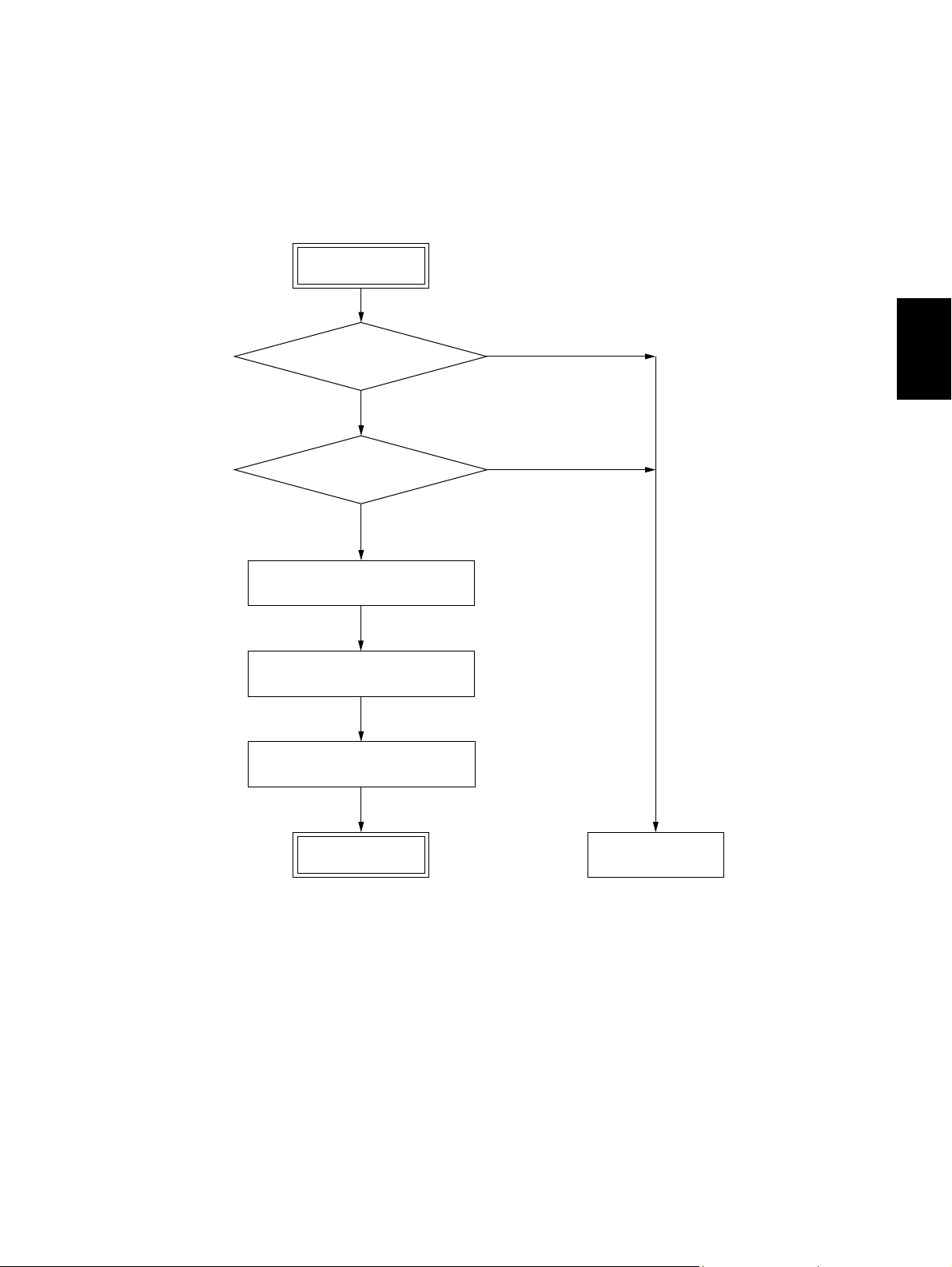
2.4.2 Print algorithm
A reception print image is basically printed on one page. Consequently, the algorithm of reception print
is in the order of same size print, discard extra, vertical reduction print, and divided print. (Refer to the
reception print flowchart.)
2
© 2006 - 2008 TOSHIBA TEC CORPORATION All rights reserved GD-1220/1221
2 - 5
LSU-RELATED FUNCTIONS
Page 24

Reception print flowchart
Start
Receive FAX
Within effective
recording area ?
NO
Fraction discard
Within
fraction discard length
range ?
Vertical reduction
Calculate reduce ratio
γ from actual image data
ON ?
ON ?
NO
YES
NO
YES
YES
YES
NO
Full-size print
Fraction discard print
Divided print
γ within max.
reduce ratio ?
NO
YES
Vertical reduction print
Judgment parameter
Effective recording area Area excluding 4 mm from the top of recording paper and 4 mm from the bottom.
Discard Function setting by user
Vertical reduction Function setting by user
Discard parameter Func. 15 bit 6, 7
GD-1220/1221 © 2006 - 2008 TOSHIBA TEC CORPORATION All rights reserved
LSU-RELATED FUNCTIONS
2 - 6
Page 25

[ 1 ] Discard printing
Func. 15 bit 2 permits selecting between ON and OFF of the option for discard extra.
Func. 15 bit 2 = 0 : OFF
Func. 15 bit 2 = 1 : ON (Default)
Func. 15 bits 6 and 7 allow the discard parameter to be set.
Func. 15 (Default Setting bit 2 = 0, bit 6 = 1, bit 7 = 0)
bit 2 bit 6 bit 7 Discard parameter
0 X X Discard OFF
1 0 0 0 mm (Discard OFF)
110 10 mm
101 17 mm
111 34 mm
• When the option for discard extra is ON:
When the length of the received document in the feed direction exceeds the effective recording area
and the part exceeding one page is within the discard parameter, printing takes place with the
exceeding part discarded. When the length of the received document in the feed direction exceeds
the discard parameter range and is within the reduction range of the maximum reduce ratio, vertical
reduction print takes place. When it is not within the reduction range of the maximum reduce ratio,
divided print takes place. The discard extra takes preference over the vertical reduction print.
Rcv. doc.
Rcd. paper
2
AA
A: Effective recording area
B: Record data length outside
effective recording area
B
Fig. 2-2
If the length of B is less than the set discard parameter, B is discarded.
• When the option for discard extra is OFF:
The vertical reduction takes preference without performing discard extra print.
© 2006 - 2008 TOSHIBA TEC CORPORATION All rights reserved GD-1220/1221
2 - 7
LSU-RELATED FUNCTIONS
Page 26

[ 2 ] Vertical reduction print
Func. 15 bit 5 permits selecting between ON and OFF of the option for Vertical reduction print.
Func. 15 bit 5 = 0 : OFF
Func. 15 bit 5 = 1 : ON (Default)
• When the option for Vertical reduction print is ON:
When the length of the received document in the feed direction exceeds the effective recording
area, the feed length is reduced in an appropriate reduce ratio and then the received document is
printed on one sheet of recording paper.
The following two patterns of maximum reduce ratio are available according to the setting of Func.
15 bit 1.
Func. 15 bit 1 = 0 : Max. reduce ratio 90 % → The reduce ratio settings of 95% and 90 % are valid.
Func. 15 bit 1 = 1 : Max. reduce ratio 73 % →The reduce ratio settings of 95 %, 90 %, 86 %, 80%,
83 % and 73 % are valid.
• When the option for vertical reduction print is OFF:
When the length of the received document in the feed direction exceeds the effective recording
area, divided print takes place.
[ 3 ] Divided print
When received data cannot be recorded on one sheet, even if reception reduction and reception discard are carried out, the recorded data is divided in the vertical direction and printed on two or more
sheets with maximum length set up in the equipment, without reduction.
If a long original with length of 216 mm which cannot be recorded on one B4 sheet with the maximum
reduction is received, when A4, B4, and A5 paper is loaded in the first, second, and third drawers,
respectively, for example, the maximum recording paper (B4) is selected and received data is divided
and printed on two or more sheets without reduction. (Refer to P. 2-13 " Table 3 Selection of recording paper (Long original)".)
Ex.1 Divided into two sheets Ex.2 Divided into three sheets
Fig. 2-3
GD-1220/1221 © 2006 - 2008 TOSHIBA TEC CORPORATION All rights reserved
LSU-RELATED FUNCTIONS
2 - 8
Page 27

[ 4 ] Similar reduction print
When recording paper of the same size as that of the received document is not available due to running
out of paper or no paper is available to cover the received document, the received document is similarly
reduced and printed on recording paper smaller than the received document.
Ex.1 To print A3-size received document on an A4-R sheet because of running out of paper.
Similar reduction
A
A
B
B
C
C
AA-R
A3
Fig. 2-4
[ 5 ] Rotation print
When recording paper of the same size as that of the received document exists but the orientations are
different on those sheets, the received document is rotated by 270 degrees before being printed. The
rotation function is performed after discard extra, reduction or dividing processing.
The rotation function is valid for received documents of A4, LT, A5, and ST-R sizes.
2
[ 6 ] Printing with no recording paper
When recording paper has run out during printing, printing takes place on another printable recording
paper starting from the next page, if available. However, if recording paper has run out in the middle of
divided print, reprinting takes place on another recording paper starting from the first one of the divided
pages. (The same operation is done when recording paper of the same size is set in a different paper
drawer.)
For the selection order of recording paper, refer to P. 2-12 " Table 2 Selection of recording paper".
© 2006 - 2008 TOSHIBA TEC CORPORATION All rights reserved GD-1220/1221
2 - 9
LSU-RELATED FUNCTIONS
Page 28
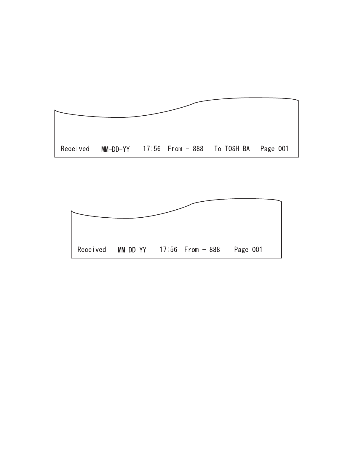
[ 7 ] RTI
When printing a received document with the RTI setting ON, RTI is printed on each page but RTI is
printed on the first page only in the case of divided print.
(ON or OFF of RTI is possible by means of the user setting. Default: OFF) RTI is created for the LT or
A4-R width. When printing RTI on A5, B5 and ST-R smaller than those sheets, the information to be
printed is reduced to a printable length.
• LT size or up
Fig. 2-5
•A5, B5, ST-R
Fig. 2-6
GD-1220/1221 © 2006 - 2008 TOSHIBA TEC CORPORATION All rights reserved
LSU-RELATED FUNCTIONS
2 - 10
Page 29

[ 8 ] Received document and selection of recording paper
The procedure for selecting recording paper handled by this machine is briefly described below.
Recording paper for reception print is selected according to the print recording paper range and priority
as listed in Table 2. A printable print recording paper range is selected according to the scanning width
and feed length of the received document. A print recording paper range is selected by taking the discard length and feed reduce ratio into consideration.
Shown is an example where an EU model is used, the discard parameter is 10 mm, the feed reduce
ratio is max. 75 %, the scanning width of the received image is A4, the number of lines received is STD
or 2000 lines. Since the scanning width is A4, the recording paper range to be selected is one of A5-R,
A4-R, FOLIO, B4 and A3.
Since 2000 lines are converted to 519 mm, a feed length to allow 390 mm to be printed on one page
with a max. reduce ratio of 75 % is selected. The recording paper length of A4 is 297 mm, the recording
paper length of B4 is 364 mm, and the recording paper length of A3 is 420 mm.
Therefore, an A3 paper range covering 390 mm is selected. After an A3 range is selected, recording
paper is selected according to the priority in Table 2, followed by printing.
Table 1 Selection of recording paper range
For NAD model
Scanning
216 mm 256 mm 303 mm
Feed length ST (140 mm) ST-R COMP LT
LT (216 mm) LT-R COMP LT
LT-R (279 mm) LT-R COMP LD
LG/COMP (356 mm) LG COMP LD
LD (432 mm) LD LD LD
Long original (over 432 mm) LT (long) COMP (long) LD (long)
2
For MJD, AUD, ASD, SAD, TWD, CND models
Scanning width
216 mm 256 mm 303 mm
Feed length A5 (148.5 mm) A5-R B5 A4
B5 (182 mm) A4-R B5 A4
A4 (210 mm) A4-R B4 A4
A4-R (297 mm) A4-R B4 A3
FOLIO (330 mm) FOLIO B4 A3
B4 (364 mm) B4 B4 A3
A3 (420 mm) A3 A3 A3
Long original (over 421 mm) A4 (long) B4 (long) A3 (long)
* When there is no recording paper which received data can be printed on one sheet of, the maximum
paper loaded in the equipment is selected and data is divided and printed on two or more sheets
without reduction. (Refer to P. 2-13 " Table 3 Selection of recording paper (Long original)".)
© 2006 - 2008 TOSHIBA TEC CORPORATION All rights reserved GD-1220/1221
2 - 11
LSU-RELATED FUNCTIONS
Page 30

Table 2 Selection of recording paper
For NAD model
Recording paper range
LT-R LT LG CO MP LD ST
Priority of
recording
paper
1LT-RLTLGCOMPLD
2
LT
*3
3LGLD
4A4-R
5
6
7
8
*3
A4
COMP
*2
LD
ST-R
*2
*1
LT-R
LG
A4
A4-R
COMP
ST-R
*2*3
*1*3
*3
*3
*2*3
COMP
LD
LT-R
LT
A4-R
A4
ST-R
For MJD, AUD, ASD, SAD, TWD, and CND models
A4-R B4 A3 A4 A5 FOLIO B5
Priority of
recording
paper
1A4-RB4 A3 A4
2
A4
*3
3 FOLIO
4LT-R
5
6
7
8
LT
B4
A3
A5-R
*3
*2
*2
*1
A3
A4-R
*1*3
A4
FOLIO
LT-R
*1*3
LT
A5-R
*2
*1
B4
A4-R
A4
*1
FOLIO
*1
LT-R
LT
*1
A5-R
*2
*2
*3
*3
*1
*2
LD
COMP
LT-R *1 LT-R * 1 LT * 3
*1*3
LT
*1
LG
*1
A4-R
*1*3
A4
ST-R
A4-R
*1
ST-R
Recording paper range
A5-R
*1
*1
*1*3
*1
*1
*1*3
*1
A4-R
A3
FOLIO
B4
LT
LT-R
A5-R
*3
*2*3
*2*3
*3
*1*3
ST-R
LT
LG
A4
A4-R
A4
*1
*1*3
*1
*1
*1*3
*1
*3
*3
LT-R
LG
A4-R
A4
COMP
LD
FOLIO B4
B4
A3
FOLIO A4-R
LT-R
LT
B4
A3
*3
*2
*2
A4
LT-R
LT
A5-R
*3
*3
*2
*2
*2
*2
*3
*3
*1
A4
A4-R
A3
FOLIO
LT
LT-R
A5-R
*2
*2*3
*2*3
*2*3
*2
*2*3
*1*3
* 1 : Similar reduction possible.
* 2 : Center printing when printing out to a size larger in the scanning direction.
* 3 : Rotation processing.
GD-1220/1221 © 2006 - 2008 TOSHIBA TEC CORPORATION All rights reserved
LSU-RELATED FUNCTIONS
2 - 12
Page 31

Table 3 Selection of recording paper (Long original)
For NAD model
Recording paper range
LT (long) COMP (long) LD (long)
Priority of
recording
paper
1
2
3LT-R
4
5LG
6A4-R
7
8
*2
LD
COMP
*3
LT
A4
ST-R
LD
*2
COMP
LT-R
LT
LG
A4-R
*3
*1
A4
ST-R
For MJD, AUD, ASD, SAD, TWD, and CND models
Recording paper range
A4 (long) B4 (long) A3 (long)
Priority of
recording
paper
1
2
3A4-R
4
5 FOLIO
6LT-R
7
8
A3
B4
A4
LT
A5-R
*2
*3
*2
*3
A3
B4
A4-R
A4
FOLIO
LT-R
LT
*1
A5-R
*2
*1*3
*1
*1*3
*2
*1*3
*1*3
LD
LT-R
*1*3
LT
LG
A4-R
*1*3
A4
ST-R
*1
*1
*1
*1
*1
2
COMP
*1
*1
*1
A3
*1
B4
*1
*1
*1
*1
A4-R
*1*3
A4
FOLIO
LT-R
*1*3
LT
A5-R
*1
*1
*1
*1
* 1 : Similar reduction possible.
* 2 : Center printing when printing out to a size larger in the scanning direction.
* 3 : Rotation processing.
© 2006 - 2008 TOSHIBA TEC CORPORATION All rights reserved GD-1220/1221
2 - 13
LSU-RELATED FUNCTIONS
Page 32

2.5 Error processing
If paper has run out or a drawer has been pulled out, follow the procedure described below.
1) If recording paper of a larger size has run out during communication:
For DIS redeclaration in the mode change procedure, declare the first recording paper size
declared, as it is.
2) If a document has been received with recording paper of a larger size empty:
Declare the maximum value of the remaining recording paper or the attached drawer. Conform to
the setting of Func. 8 bit 4.
3) If the drawer has been pulled out:
Assume A4 if none of the drawers is left.
4) If all paper has run out:
When the recording paper width capacity is recording paper and all paper has run out, assume A4.
(Same processing is done when only the recording paper of scan width less than 216 mm is set.)
GD-1220/1221 © 2006 - 2008 TOSHIBA TEC CORPORATION All rights reserved
LSU-RELATED FUNCTIONS
2 - 14
Page 33

2.6 Limitations on reception print
The following limitations are imposed on reception print.
1) Reception print is not performed from the SFB.
2) Even if the ADU is installed, it cannot be used.
3) When illegal paper is selected and printed on due to an operator mistake, the completion of printout
is assumed and no printout is performed again.
4) The feed length of a received document is not limited. That is, printing is performed even if the
received document has several lines for printing. However, if the top lines are less than 5 lines, no
printing takes place. This also applies to multiple pages in divided print.
5) Paper of the same size is present in multiple drawers, printing takes place according to the following
drawer priority.
Order Drawer
1 Drawer selected by code 480 in system mode
2 1st drawer
3 2nd drawer
4 3rd drawer
5 4th drawer
2
© 2006 - 2008 TOSHIBA TEC CORPORATION All rights reserved GD-1220/1221
2 - 15
LSU-RELATED FUNCTIONS
Page 34

GD-1220/1221 © 2006 - 2008 TOSHIBA TEC CORPORATION All rights reserved
LSU-RELATED FUNCTIONS
2 - 16
Page 35
3. DIALING/COMMUNICATION CONTROL
3.1 Circuit Connection and Procedure to Change Mode
3.1.1 Dial call-up transmission to a telephone circuit
START
Detecting a calling signal?
NO
Detecting an off-hook signal?
NO
DC circuit closed
After detecting the dial tone,
or 3.3 seconds elapsed
Selection signal sent out
YES
YES
3
END
© 2006 - 2008 TOSHIBA TEC CORPORATION All rights reserved GD-1220/1221
3 - 1
Standby state
DIALING/COMMUNICATION CONTROL
Page 36

3.1.2 Selection of the communication mode
This machine has three types of communication mode. The mode to be used is determined according
to the combination of the types of the circuits and communication and available function of the other
side’s machine.
Communication mode
Toshiba original procedure ECM G3
Telephone circuit {{{
3.1.3 Procedure to select the transmission mode
START
*1
Other side machine has the
Toshiba original
procedure mode?
YES
Communication using the
Toshiba original procedure
NO
Other side machine has
ECM mode?
NO
Other side machine has G3 mode?
YES
YES
ECM communication
G3 communication
*1 This step is only checked when the other side machine has CRP2 (+ CRP1) or when the trans-
mission is started by the CRP calling. (The first transmission to the other side with CRP1 only
is performed in the ECM mode.)
GD-1220/1221 © 2006 - 2008 TOSHIBA TEC CORPORATION All rights reserved
DIALING/COMMUNICATION CONTROL
3 - 2
Page 37

3.2 Signaling System Diagram and Signal Forms
3.2.1 Circuit control signals
The following circuit control signals are used in the binary and tonal procedures.
• Circuit control signals
CED Called station identification
Indicates that the sender is a FAX machine in the automatic called
mode. (*1)
CNG Calling tone
Indicates that the sender is a FAX machine in the automatic calling
mode. (*1)
*1: This signal can be sent manually.
• Signal form
Signal name Signal form Signal form
CED f: 2100 ±15 Hz
CNG f: 1100 ±38 Hz
f
t
f
t
f
L
t
t: 2.6 - 4.0 sec
t: 0.5 sec ±15%
(L: 3 sec)
3
© 2006 - 2008 TOSHIBA TEC CORPORATION All rights reserved GD-1220/1221
3 - 3
DIALING/COMMUNICATION CONTROL
Page 38

3.2.2 Communication with the binary signals
In the Toshiba original procedure/G3 modes, communication is performed with the binary procedure as
follows.
1) Binary procedure
- Transmission and reception in the Toshiba original procedure/G3 modes
Transmtter Receiver
CED
NSF•CSI•DIS
NSS•TSI•DCS
Training
TCF
CFR
Image signal
Mode ch a n ge pos s ible*
Informing that there is
the next page
EOM
MCF
NSF•CSI•DIS
NSS•TSI•DCS
Training
TCF
CFR
Image signal
MPS
MCF
Image signal
MCF
DCN
* Mode change is possible only for the original set manually.
GD-1220/1221 © 2006 - 2008 TOSHIBA TEC CORPORATION All rights reserved
DIALING/COMMUNICATION CONTROL
3 - 4
Page 39
- Transmission and reception in the ECM mode
ECM (Error Correction Mode) conforms to T.30.
When an error has occurred to the received image data, the receiving station informs the sending
station of the occurrence of the error, and the sending station sends the image data again.
Transmtter Receiver
CED
NSF•CSI•DIS
NSS•TSI•DCS
Training
TCF
Only error frame retransmitted
Page 1 completed
Image s
CFR
Image signal
PPS NULL
MCF
Image signal
PPS MPS
PPR
ignal retransmitted
PPS MPS
MCF
Image signal
PPS EOP
3
256 frames received
Error occurred
MCF
Page 2 completed
© 2006 - 2008 TOSHIBA TEC CORPORATION All rights reserved GD-1220/1221
DCN
DIALING/COMMUNICATION CONTROL
3 - 5
Page 40

- Cancellation during the transmission
If the [CLEAR/STOP] button is pressed during the direct transmission or memory input, the display to confirm the cancellation appears. The communication is finished normally regardless of
the presence/absence of the next page or mode changes by pressing the [CLEAR/STOP] button.
If the [CLEAR/STOP] button is pressed anytime except during the transmission of the image
data, DCN is forcibly sent to terminate the communication.
To cancel the job during the memory transmission or the polling transmission job, press the [JOB
STATUS] button on the External Keyboard, select the transmission job to cancel, and then press
the [ ] button on the LCD display.
Transmtter
[
JOB STATUS] button
[
CANCEL] button
CED
NSF•CSI•DIS
NSS•TSI•DCS
Training
TCF
CFR
Image signal
EOP
MCF
DCN
Receiver
GD-1220/1221 © 2006 - 2008 TOSHIBA TEC CORPORATION All rights reserved
DIALING/COMMUNICATION CONTROL
3 - 6
Page 41

2) Binary signals
NSF Non-Standard Facility
Informs that the receiving station (machine) has a non-standard facility.
NSC Non-Standard Facility Command
Command to transmit using the non-standard facility which is selected corresponding to NSF (i.e.,
Polling etc.).
NSS Non-Standard Facility Setup
Command to transmit using the non-standard facility which is selected corresponding to NSF or
NSC.
CSI Called Subscriber Identification
Provides the telephone number of the called station. Used to check the identity of the called station.
CIG Calling Subscriber Identification
Provides the telephone number of the calling station. Used to check the identity of the calling station (Polling, etc.).
TSI Transmitting Station Identification
Provides the telephone number of transmitting station. Used to check the identity of the transmitting station.
DIS Digital Identification Signal
Informs that the receiving station (machine) has a standard facility (G3/G2).
DTC Digital Transmit Command
Command to transmit using the standard facility which is selected corresponding to DIS (i.e., Polling, etc.).
DCS Digital Command Signal
Commands to transmit using the standard facility which is selected corresponding to DIS or DTC.
SUB Sub-address
Indicates that the FIF information is a sub-address in the domain on the call-in side.
SEP Select Polling
Indicates that the FIF information is a sub-address for the polling mode.
PWD Password
Indicates that the FIF information is a password for the polling mode in a reception.
Indicates that the FIF information is a password for transmission in a transmission.
3
CFR Confirmation of Reception
Informs that the FAX is ready to receive data.
FTT Failure to Train
Informs that the TCF signal has not received correctly and requests the re-training.
EOM End of Message
Informs that the the 1st page has been transmitted and there is the next page; command to return
to the beginning of the phase B.
MPS Multi-page Signal
Informs that the 1st page has been transmitted and there is the next page; command to return to
the beginning of the phase C.
EOP End of Procedure
Informs that a document has been transmitted and there is no more pages.
MCF Message Confirmation
A reply to MPS, EOM or EOP; informing that image signals have been received correctly and the
FAX is ready to receive data.
RTN Retrain Negative
Informs that a document has not been received correctly; requests for the retraining or phase synchronization to receive the next page.
© 2006 - 2008 TOSHIBA TEC CORPORATION All rights reserved GD-1220/1221
3 - 7
DIALING/COMMUNICATION CONTROL
Page 42

PIP Procedure Interrupt Positive
Informs that the image signals have been received correctly and requests the operator’s reply by
telephone or to return to the beginning of the phase B to continue the communication (i.e., CALL
Request, etc.).
PIN Procedure Interrupt Negative
Informs that the image signals have not been received correctly and requests for operator’s reply
by telephone or to return to the beginning of the phase B to continue the communication.
PRI-EOM Procedure Interrupt EOM
Command similar to EOM. Operation by operator is necessary.
PRI-MPS Procedure Interrupt MPS
Command similar to MPS. Operation by operator is necessary.
PRI-EOP Procedure Interrupt EOP
Command similar to EOP. Operation by operator is necessary.
DCN Disconnect
Command to disconnect the FAX line and to connect the telephone line. Reply from the other side
is not necessary.
RR Receive Ready
Informs that the FAX is ready to receive documents and requests for data to set the reception
mode. (ECM mode)
RNR Receive Not Ready
Informs that the FAX is not in the receivable state. (ECM mode)
PPR Partial Page Request
Informs that a part of page (ECM block) has not been received correctly. The number of the frame
needs to be corrected is informed by the FIF. (EC mode)
PPS Partial Page Signal
Informs that a part of page (ECM block) or one page has been transmitted. (EC mode)
CTC Continue to Correct
Replies to the 4th PPR which requests to correct the image signal; informs that the transmitting
station will continue to correct the frame data. (ECM mode)
CTR Response for Continue to Correct
Replies to CTC and informs that the receiving station has received and accepted the CTC. (EC
mode)
EOR End of Retransmission
Informs that the transmitting station has completed the correction of the error frame data (binary
signal) of the previous ECM block. (ECM mode)
ERR Response for End Retransmission
Replies to EOR and requests to transmit the image signal of the next ECM block. (ECM mode)
RTP Retrain Positive
Informs that the message has been received completely and that the subsequent message can be
continued after receiving the synchronization signal and CFR signal.
CRP Command Repeat
Requests to resend all the commands including optional frames because the preceding command
has been received incorrectly.
GD-1220/1221 © 2006 - 2008 TOSHIBA TEC CORPORATION All rights reserved
DIALING/COMMUNICATION CONTROL
3 - 8
Page 43

3) Frame structure of binary signals
Each binary signal frame is comprised of the following sequence and fields. However, some binary
signals do not have the FIF field inserted.
FFACFCFFIFFCSF
Preample
F : Flag sequence
Indicates the start or end of a frame. Also establishes the frame synchronization.
A : Address field
Informs the address.
C : Control field
Informs if this frame is the last one in this procedure.
FCF: FAX control field
Informs the type of the binary signal.
FIF: FAX information field
Informs FAX information such as the functions.
FCS: Frame check sequence
Checks if there was any error in the transmission from A to FIF.
- Format of F, A and C
Format
b
1
F 01111110
A 11111111
C 1100x000
b
2
b
3
b
4
b
5
b
6
b
7
* When this frame is the last frame, X = 1.
3
b
8
© 2006 - 2008 TOSHIBA TEC CORPORATION All rights reserved GD-1220/1221
3 - 9
DIALING/COMMUNICATION CONTROL
Page 44

- FCF format of each binary signal
Binary signal
b
1
b
2
b
3
NSF 00000100
NSC 10000100
NSS x1000100
CSI 00000010
CIG 10000010
TSI x1000010
DIS 00000001
DTC 10000001
DCS x1000001
SUB x1000011
SEP 10000101
PWD(Rx)10000011
PWD(Tx)x1000101
CFR x0100001
FTT x0100010
EOM x1110001
MPS x1110010
EOP x1110100
MCF x0110001
RTN x0110010
PIP x0110101
PIN x0110100
PRI-EOMx1111001
PRI-MPSx1111010
PRI-EOPx1111100
DCN x1011111
RR x1110110
RNR x0110111
PPR x0111101
PPS x1111101
CTC x1001000
CTR x0100011
EOR x1110011
ERR x0111000
RTP x0110011
CRP x1011100
b
4
Format
b
5
b
6
b
7
b
8
- X = 1 for the station which received DIS.
- X = 0 for the station which received a response signal to DIS.
GD-1220/1221 © 2006 - 2008 TOSHIBA TEC CORPORATION All rights reserved
DIALING/COMMUNICATION CONTROL
3 - 10
Page 45

4) Training
The training is performed in the binary procedure to surely transmit the image signals.
- Training signal
The training signal is transmitted following the DCS signal at the modem speed specified by the
DCS signal. Responding to this training signal, the receiving side adjusts the auto-equalizer.
- Format of the training signal
14.4 Kbps, 12 Kbps
Segment 1 Segment 2 Segment 3 Segment 4
Alternation
of ABAB
106 msec 1240 msec 27 msec 20 msec
- 9600 bps, 7200 bps
Segment 1 Segment 2 / Segment 3 Segment 4
No signal
V.29
20 msec 53 msec+160 msec 20 msec
- 4800 bps, 2400 bps
Segment 1Segment 2 Segment 3 Segment 4
Non-
V.27ter
modulated
carrier
Equalizer
adjustment
pattern
No signal
Chain-store
information
sequence
1393 msec
Repeating 2-state
signal
(
Binary
253 msec
Continuous
180° phase
inversion
(
Binary
Scrambled binary data “1”
Scrambled data “1”
)(
0° to 180°
2-phase pattern
)
Hexa or octal
(
Binary
)
TCF
TCF
)
Segment 5
Scrambled data “1”
(
Hexa or octal)
3
TCF
4,800 bps: 923 msec,
2,400 bps: 1158 msec
- TCF signal
An error may occur in the image data if the training is not performed correctly. The transmitting
side sends a TCF signal and checks if any error occurs in image data before the image data
communication to follow. When the receiving side detects an error in the TCF signal, it transmits
an FTT signal to the transmitting side to request the retraining. When there is no error, the receiving side transmits a CFR signal.
The TCF signal transmits all zeros for 1.5 seconds at the same modem speed as that for the
training signal.
© 2006 - 2008 TOSHIBA TEC CORPORATION All rights reserved GD-1220/1221
3 - 11
DIALING/COMMUNICATION CONTROL
Page 46

3.2.3 V.8/V.34 communication sequence
1) Outline
- V.8 is performed as a startup procedure to switch to V.34. V.8 can connect an existing facsimile
machine to the equipment using a data modem or other V-series modems. The V.34 modem has
a modem circuit previously recommended, allowing it to be also connected to the existing
modems while they are upper compatible.
- New technologies such as the pre-emphasis technology *1 and the probing technology *2 are
fully used. The pre-emphasis technology *1 not only speeds up the modulation, but also gains
the S/N ratio. The probing technology examines the line characteristics and optimizes the
modem for the line condition. Therefore, not only do these technologies speed up the transmission momentarily, but also the average speed of the process during the data transmission is
increased.
- For V.8 and the pre/post-FAX transmission for V.34, the procedure is speeded up by the full
duplex communication.
- Following 14 types of the image transmission speed are available: *3
33.6 kbps/31.2 kbps/28.8 kbps/26.4 kbps/24.0 kbps/21.6 kbps/19.2 kbps/16.8 kbps/14.4 kbps/
12.0 kbps/9.6 kbps/7.2 kbps/4.8 kbps/2.4 kbps
- The modulating speed (baud rate) *4 can be selected from 2,400, 3,000, 3,200 symbol/sec (man-
datory), or 2,743, 2,800, 3,429 symbol/sec (option). The data rate can be set more accurately
than the conventional modem.
*1 A signal is sent while raising the output level in the high-frequency band in which the noise
is relatively loud.
*2 Tone signal called “Probing Tone” is sent for the receiver to examine the line characteris-
tics of the line.
*3 In the ITU-T Recommendation, it is described as “data rate”. “Image transmission speed”
is the same as “data rate”.
*4 In the ITU-T Recommendation, it is described as “symbol speed”. The “Symbol rate”,
“Modulating speed”, and “Baud rate” are the same thing. This machine cannot realize the
speed of 2,743 symbol/sec.
Notes:
1. ECM is used in the V.34 procedure. If the setting for the ECM transmission/reception of the
user data is set to “Not performed”, the V.8 procedure is not performed and the procedure is
not switched to V.34. V.17 or lower is selected in this case.
2. When the transmission/reception speed is set to 14.4 kbps or slower, the V.8 procedure is not
performed, and V.17 or lower is selected.
3. See “Late start (P3-20)” to move to the V. 8/V.34 procedure after starting with the V.21 procedure.
4. After the V.34 procedure is started, the fallback for the V.34 procedure is performed.
However, the fallback for the V.17 mode or lower mode is not performed.
GD-1220/1221 © 2006 - 2008 TOSHIBA TEC CORPORATION All rights reserved
DIALING/COMMUNICATION CONTROL
3 - 12
Page 47

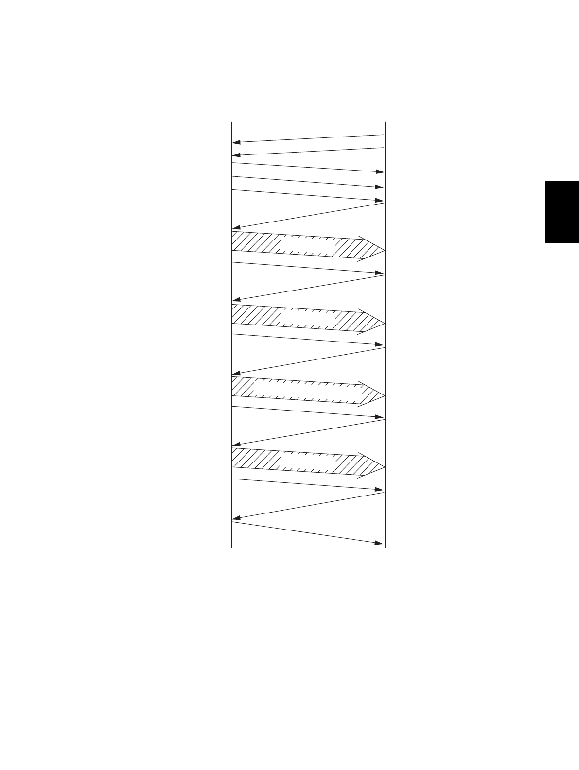
2) Standard procedure
Transmitter Receiver
Network interaction
(
Phase 1
)
( P3-14)
Probing/Ranging
(
Phase 2
)
( P3-15)
Equalizer/Echo
canceller training
(
Phase 3
)
( P3-16)
Final training
(
Phase 4
)
( P3-16)
Control channel
( P3-17)
Line closed
The available modulation mode is in formed.
Each declares that it has V.34 capability. The
procedure moves to V.34 in the phase 2.
After the information about the modem capability is exchanged, the receiver determines
the modulation speed based on the result of
reception of the probing signal which was sent
by the transmitter.
To determine the image transmission speed,
the transmitter sends a training signal.
The optimum image transmission speed is
determined according to the training signal
received.
The pre-FAX transmission which is the same
as that for the normal T.30 is performed at
1,200 bps.
3
The training signal is sent with the determined
Primary channel
parameter, then the image data are sent.
( P3-18)
Image data
( P3-18)
The post-FAX transmission which is the same
as that for the normal T.30 is performed at
Communication
1,200 bps.
end procedure
( P3-19)
Line opened
© 2006 - 2008 TOSHIBA TEC CORPORATION All rights reserved GD-1220/1221
Line opened
DIALING/COMMUNICATION CONTROL
3 - 13
Page 48

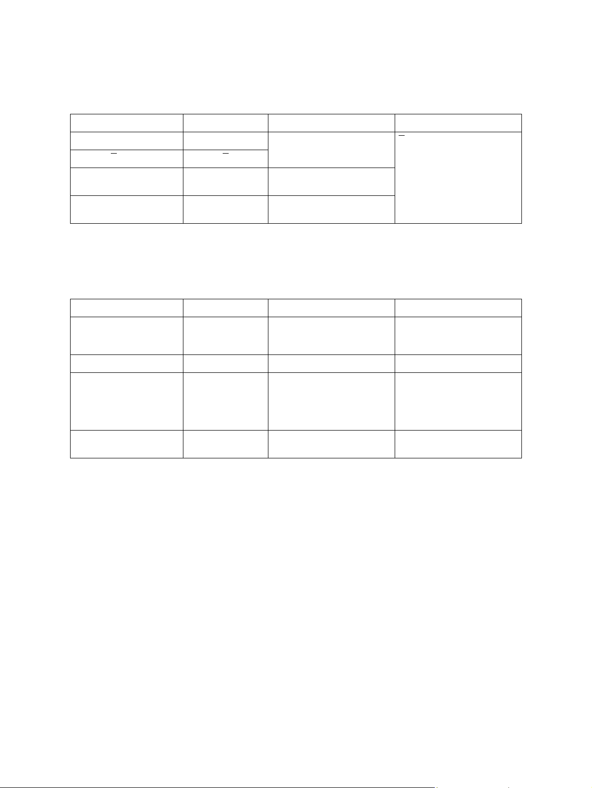
- Network interaction (Phase 1)
The V.8 procedure is performed as the startup procedure for the V.34 high-speed modem.
In the V.8 procedure, mainly the optimum modulation method (V series modem mode) that can
be operated between the transmitter and receiver is determined.
Transmitter
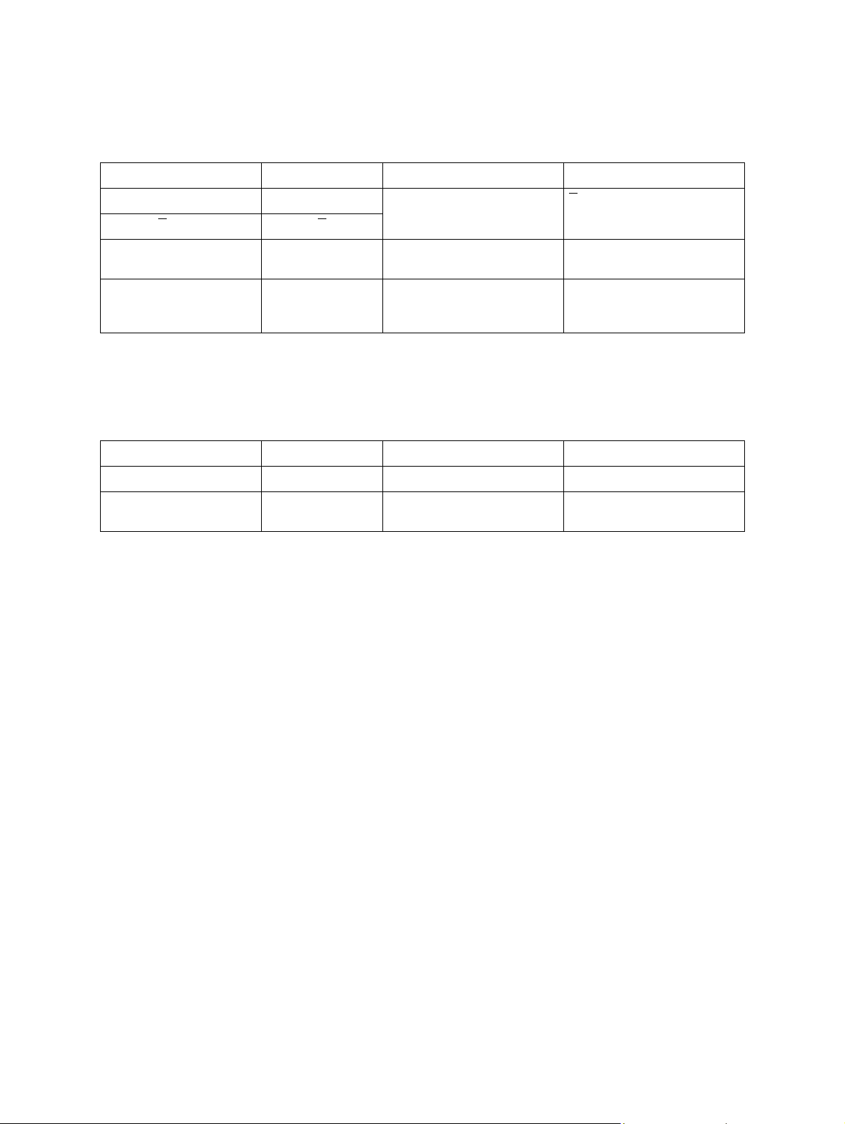
Signal name Abbreviation Function Remarks
Calling tone CNG 1100 Hz tone signal specified
by T.30 indicating the sender
is a FAX machine in the automatic calling mode.
Call Menu signal CM Mainly indicates an available
modulation method such as
V.21, V.27ter, V.29, V.17,
V.34, etc.
CM terminator CJ Indicates the detection of the
JM signal or the termination of
CM signal.
Call Indicator signal CI Indicates the general commu-
nication functions. It is sent
when the V.8 procedure is
restarted.
Modulated by V.21 (L) *1.
Transmission rate: 300 bps
Modulated by V.21 (L) *1.
Transmission rate: 300 bps
For the late start only.
(P3-20)
Modulated by V.21 (L) *1.
Transmission rate: 300 bps
Receiver
Signal name Abbreviation Function Remarks
Answer amplitude tone ANSam 2100 Hz tone signal ampli-
tude-modulated to 15 Hz.
Joint Menu signal JM Indicates the terminal type
such as a FAX machine.
Response to a CM sent from
the transmitter and informs
available modulation method.
Tone equivalent to CED of the
conventional machine.
Modulated by V.21 (H) *1.
Transmission rate: 300 bps
-
*1 V.21 (L) ..........Low frequency channel defined by the V.21 recommendation 1,080±100 Hz
(980 Hz: 1, 1,180 Hz: 0)
V.21 (H) ..........High frequency channel defined by the V.21 recommendation 1,750±100 Hz
(1,650 Hz: 1, 1,850 Hz: 0)
GD-1220/1221 © 2006 - 2008 TOSHIBA TEC CORPORATION All rights reserved
DIALING/COMMUNICATION CONTROL
3 - 14
Page 49

- Probing/Ranging (Phase 2)
Examines the line characteristics and sets the parameters for the modulation related items such
as the modulating speed.
Transmitter
Signal name Abbreviation Function Remarks
INFO sequence INFO0c Informs the modem capability
such as modulating speed
and frequency transmission
capability (two frequency
bands (high and low) used to
examine the line characteristics), and requests for adjusting.
Tone B B Synchronization between the
Tone B B
Line probing signal L1 L1 Tone signal to analyze the line
Line probing signal L2 L2
modems by 1200 Hz tone signal
characteristics by probing
Transmission rate: 600 bps
B
is a signal that shifts the
phase B 180°.
Probing is to examine the line
characteristics.
Tone signal between 150
Hz and 3,750 Hz in units of
150 Hz
Receiver
Signal name Abbreviation Function Remarks
INFO sequence INFO0a Informs the modem capability
such as the modulating speed
and frequency transmission
capability.
Tone A A Synchronization between the
Tone A A
modems by 2,400 Hz tone
signal
Transmission rate: 600 bps
A
is a signal that shifts the
phase A 180°.
3
INFO sequence INFO0h Based on the analysis of the
line probing signal sent from
the transmitter, it informs the
pre-emphasis filter and modulating speed to be used for the
data transmission.
© 2006 - 2008 TOSHIBA TEC CORPORATION All rights reserved GD-1220/1221
3 - 15
Transmission rate: 600 bps
DIALING/COMMUNICATION CONTROL
Page 50
- Equalizer and echo canceller training (Phase 3)
Training (adjustment) is performed according to the parameters set in the phase 2 to optimize the
filters such as an equalizer.
Transmitter
Signal name Abbreviation Function Remarks
S signal S Short training S is a signal made as the
S signal S
PP signal PP Used by the modem of the
receiver to train the equalizer.
TRN signal TRN Used by the receiver to deter-
mine the transmission rate.
result of phase transition of S.
- Final training (Phase 4)
The settings such as the maximum value for the data rate, selection of the trellis encoder, and
data rate which can be supported are made in this phase.
Transmitter/receiver
Signal name Abbreviation Function Remarks
PPh signal PPh Used by the modem of the
other side to train the equalizer.
ALT signal ALT -
Modulation parameter MPh Informs the parameters used
for the image transmission
such as maximum data signal
rate and type of the trellis coding/pre-coding.
E sequence E - 20 bit sequence of “1”s in
binary
GD-1220/1221 © 2006 - 2008 TOSHIBA TEC CORPORATION All rights reserved
DIALING/COMMUNICATION CONTROL
3 - 16
Page 51

- Control channel
The conventional T.30 procedure is performed. The transmission rate is 1200 bps.
Transmitter
Signal name Abbreviation Function Remarks
Flag flags Maintains the synchroniza-
tion.
Non-standard facilities
setting
Transmitting Subscriber
ID
Digital Command Signal DCS Specifies the mode that can
- 1 Declares to switch to the high-
NSS Receives an NSF sent from
the receiver. It selects the
available mode from the
received NSF, and specifies
the mode for the reception.
TSI Informs the telephone number
of the transmitter.
be used for the communication.
speed procedure.
7E (H)
“1” is sent continuously.
Receiver
Signal name Abbreviation Function Remarks
Non-Standard Facilities NSF Informs the presence of the
facilities other than those recommended by ITU-T, abbreviated user names, and
manufacturer codes, etc.
Called Subscriber ID CSI Informs the telephone number
of the receiver.
3
Digital Identification Signal DIS Informs the standard facilities
Flag flags Maintains the synchroniza-
Confirmation for Recep-
tion
CFR Informs that the training of the
recommended by ITU-T.
7E (H)
tion.
modem is completed, and the
receiver is ready to receive
the image signal.
Reference: In the control channel, the frequency of the signals to be sent is different
between the transmission and reception. The signal echoed back has never
been misidentified as a signal sent from the other side. Therefore, this channel is
not influenced by signals echoed back.
© 2006 - 2008 TOSHIBA TEC CORPORATION All rights reserved GD-1220/1221
3 - 17
DIALING/COMMUNICATION CONTROL
Page 52
- Primary channel
The training is performed according to the parameters set in the phase 4. The transmission rate
is 1,200 bps.
Transmitter
Signal name Abbreviation Function Remarks
S signal S Short training S is a signal that makes a
S signal S
PP signal PP Used by the modem of the
receiver to train the equalizer.
B1 sequence B1 Scrambled data frame to be
sent when the startup process
is completed
transition from phase S.
- Image data
Image data are sent.
Transmitter
Signal name Abbreviation Function Remarks
Image data Image data Encoded image data
- Turn off - Scrambled 1 is sent for 35
ms.
GD-1220/1221 © 2006 - 2008 TOSHIBA TEC CORPORATION All rights reserved
DIALING/COMMUNICATION CONTROL
3 - 18
Page 53

- Communication end procedure
This procedure is to terminate the communication. The transmission rate is 1,200 bps.
Transmitter
Signal name Abbreviation Function Remarks
Sh signal Sh Short training
Sh signal Sh
ALT signal ALT -
E sequence E -
End of procedure signal PPS-EOP The transmission of one page
is completed.
Flag flags Maintains the synchroniza-
tion.
Disconnection signal DCN Informs to disconnect the line.
7E (H)
Receiver
Signal name Abbreviation Function Remarks
Sh signal Sh Short training
Sh signal Sh
3
ALT signal ALT -
E sequence E -
Flag flags Maintains the synchroniza-
tion.
Message confirmation MCF Indicates that the image sig-
nal is received normally, and
the receiver is ready to
receive the next page.
7E (H)
© 2006 - 2008 TOSHIBA TEC CORPORATION All rights reserved GD-1220/1221
3 - 19
DIALING/COMMUNICATION CONTROL
Page 54
3) Example of protocol
The signals shaded in the following figure are the most important signals in the procedure.
- Late start
The receiver cannot detect CM signal while it is sending the ANSam signal. Therefore, it sends a
DIS signal to inform the availability of V.8 support. The transmitter sends a CI signal that causes
the receiver to send another ANSam signal which makes the receiver move to the V.8 procedure.
Transmitter Receiver
Line closed
(
DIS cannot
be recognized
)
GD-1220/1221 © 2006 - 2008 TOSHIBA TEC CORPORATION All rights reserved
DIALING/COMMUNICATION CONTROL
3 - 20
Page 55

- Multi-page sequence
In the same manner as the T.30 procedure, the transmitter sends a PPS-MPS signal after sending the image data. The receiver sends an MCF signal and moves to the next page transmission.
Transmitter Receiver
3
© 2006 - 2008 TOSHIBA TEC CORPORATION All rights reserved GD-1220/1221
3 - 21
DIALING/COMMUNICATION CONTROL
Page 56

- Mode change
The transmitter and receiver send a PPS-EOM signal and an MCF signal respectively. Then the
receiver and transmitter send a DIS signal and a DCS signal respectively to change the mode.
Transmitter Receiver
GD-1220/1221 © 2006 - 2008 TOSHIBA TEC CORPORATION All rights reserved
DIALING/COMMUNICATION CONTROL
3 - 22
Page 57

- Change of the image transmission speed by the receiver
The receiver sends a PPh signal responding to an Sh signal sent from the transmitter. Then, the
image transmission speed is determined according to the MPh sequence sent from the both
modems.
Transmitter Receiver
3
© 2006 - 2008 TOSHIBA TEC CORPORATION All rights reserved GD-1220/1221
3 - 23
DIALING/COMMUNICATION CONTROL
Page 58

- Change of the image transmission speed by the transmitter
The transmitter sends a PPh signal after sending the image data. The receiver returns a PPh signal. Then, the image transmission speed is determined according to the MPh sequence sent
from the both modems.
Transmitter Receiver
GD-1220/1221 © 2006 - 2008 TOSHIBA TEC CORPORATION All rights reserved
DIALING/COMMUNICATION CONTROL
3 - 24
Page 59

3.3 FAX Automatic Switching
3.3.1 General functions
There are two types of setting for the FAX Auto-Switching Mode Selection: TEL Mode and FAX Mode.
3.3.2 TEL mode
This mode is selected to prioritize telephone communication when the frequency of the fax reception is
low. When the TEL mode is selected, the automatic FAX reception function does not work. Therefore,
when a calling signal comes from the exchange, the telephone ringer continues ringing until the operator picks up the handset. When the operator has learned that the caller is sending a FAX, he has to perform the manual reception operation.
3.3.3 FAX mode
This mode is selected when the telephone circuit is used only for FAX communication. When the FAX
mode is selected and a calling signal comes from the exchange, the FAX reception operation starts
automatically without ringing the telephone ringer.
In the FAX mode, a calling number can be set up to 15 calls in the SET FUNCTION (FUNC 14 Bits 7 to
4).
<Method of judging CNG detection>
3
0.5s 3s
CNG
CNG-on detection T1
• As shown above, after CNG-on detection time T1 (175 ms) and CNG-off detection time T2 (350 ms)
have elapsed, and the T1 period has been turned on and then the T2 period off, CNG is determined
to have occurred once.
CNG-off
detection T2
CNG-determined
© 2006 - 2008 TOSHIBA TEC CORPORATION All rights reserved GD-1220/1221
3 - 25
DIALING/COMMUNICATION CONTROL
Page 60

GD-1220/1221 © 2006 - 2008 TOSHIBA TEC CORPORATION All rights reserved
DIALING/COMMUNICATION CONTROL
3 - 26
Page 61
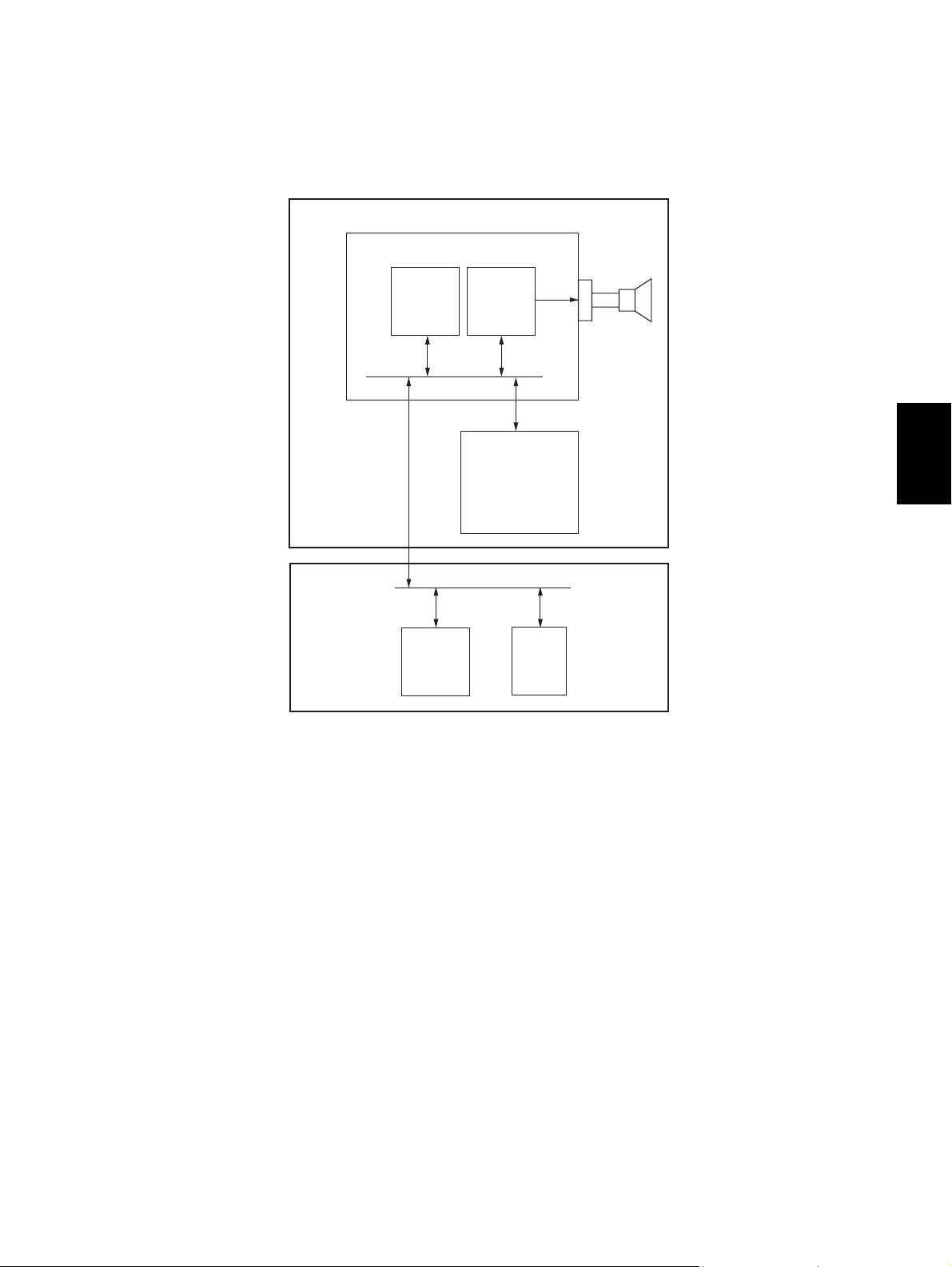
4. ELECTRICAL CIRCUITS
4.1 Configuration
GD-1220/1221
FAX board
Speaker
MAIN board
V.34 MODEM
ASIC
Analog SW
4
NCU board
SoC
Fig. 4-1
© 2006 - 2008 TOSHIBA TEC CORPORATION All rights reserved GD-1220/1221
4 - 1
08/08
ELECTRICAL CIRCUITS
Page 62

4.2 Description of Circuits
4.2.1 Configuration
This section describes the function of each circuit.
The NCU board consists of the transformer, relay, analog switch and other peripheral devices. It controls switching of the line path, generates the dial pulses, detects the line current and ring signal, and
monitors the line.
NA/TW models
Line
External
telephone
NCU board
Lb
CN10CN11
La
a2
b2
Line current
detection
circuit
-
consumption
circuit
RLY2
CML relay
REVA
REVB
IC52
IC53
IC52
CNG signal
detection
circuit
TXOUT
RXIN
ANSDET
ATT3DB
CML
LD
FAX board
CN9
CI
T1
IC51
IC53
AG
~
DB1
+
~
Dial pulse
generation
circuit
DC
1
0
1
0
Ring signal
detection
circuit
Analog
switch
Fig. 4-2
GD-1220/1221 © 2006 - 2008 TOSHIBA TEC CORPORATION All rights reserved
ELECTRICAL CIRCUITS
4 - 2
Page 63

EU/AU/AS/C models
Line
External
telephone
NCU board
Lb
La
CN3
a2
b2
RLY3
CML relay
Line current
detection
1
0
1
0
circuit
Dial pulse
generation
-
Ring signal
circuit
detection
circuit
REVA
REVB
CML
LD
IC5
T1
RLY4
Relay
AG
~
DB1
+
DC
consumption
~
circuit
Analog
switch
IC6
IC3
IC6
Analog
switch
IC4
IC4
CNG signal
detection
circuit
TXOUT
ATT3DB
RXIN
ANSDET
RLADJ1
RLADJ2
CI
FAX board
CN4
4
Fig. 4-3
© 2006 - 2008 TOSHIBA TEC CORPORATION All rights reserved GD-1220/1221
ELECTRICAL CIRCUITS
4 - 3
Page 64

4.2.2 Line path switching control circuit
NA/TW models
27
62
]
MAIN board
CN5
CN5
6227142
144
IC23
ASIC
Line
External
telephone
NCU board
Lb
4
CN10CN11
3
La
3
a2
4
b2
+12V
C5 R4
CML relay
9
4
RLY2
FAX board
3
3
6
CN262
1
2
TXOUT1
RXIN1
CML1
ATT3DB1
28,29
[
25,26
[29]
]
IC12
[
IC2
32
MODEM
Q51
R67
R71
9,11
IC51
10
Analog
switch
1
3
4
0
R59
1
7
1
15
2
0
1
13
14
0
T1
AG
AG
Ring signal
detection
circuit
IC53
5
6
R66
R68
121
1
8
0
10
1
0
3
6
IC53
112
IC52
672
CN9
Fig. 4-4
The line path switching control circuit consists of the CML relay (RLY2) and analog switch (IC51) on the
NCU board, the ASIC (IC23) on the MAIN board and the other peripheral devices.
The CML relay is switched according to the CML1 signal output from the ASIC on the MAIN board.
When the CML1 signal goes HIGH, Q51 comes on to turn ON the CML relay.
The analog switch is switched according to the CML1 signal and ATT3DB1 signal. When the CML1 signal or ATT3DB1 signal goes HIGH, the analog switch is turned ON.
Turning ON the CML relay and analog switch allow the MODEM to be connected to the line.
Signal Name Type Active Description Destination
CML1 O H Line 1 CML Relay Control Signal RLY2, IC51
ATT3DB1 O H Line 1 Attenuator Control Signal IC51
* Values in [ ] are GD-1221 in case that the descriptions vary between GD-1220 and GD-1221.
GD-1220/1221 © 2006 - 2008 TOSHIBA TEC CORPORATION All rights reserved
ELECTRICAL CIRCUITS
4 - 4
08/08
Page 65

EU/AU/AS/C models
Line
External
telephone
NCU board
Lb
4
La
3
CN3
2
a2
5
b2
Line current
detection
circuit
Relay
2
4
Ring signal
C7
RLY4
detection
circuit
Q4
547
IC7
Analog switch
13
14
15
16
IC6
IC5
0
1
2
3
11310
1
2
IC6
12
11
IC3
10
Analog
switch
R11
1
1
15
2
0
1
13
12
IC4
14
67
0
AG
3
1
R28
T1
AG
R29
C13
R31
R36
C12
R32
R30
C14
Q9
AG
RLY3
+12V
CML relay
121
R26
5
4
013
8
9
0110
+12V
FAX board
3
6
7
8
CN4
1
2
3
6
7
8
CN262
1
2
TXOUT1
RXIN1
CML1
ATT3DB1
RLADJ11
RLADJ21
28,29
[
25,26
[29]
32
]
MODEM
IC12
[
MAIN board
21
144
21
22
142
22
29
63
]
IC2
IC23
141
29
CN5
CN5
ASIC
63
140
Fig. 4-5
The line path switching control circuit consists of the CML relay (RLY3) and analog switch (IC3, IC5) on
the NCU board, the ASIC (IC23) on the MAIN board, and the other peripheral devices. It changes the
path for the FAX send/receive signals and connects it to each control circuit.
The CML relay is switched according to the CML1 signal output from the ASIC on the MAIN board.
When the CML1 signal goes HIGH, Q4 comes on to turn ON the CML relay.
4
The analog switch (IC3) is switched according to the CML1 signal and ATT3DB1 signal. When the
CML1 signal or ATT3DB1 signal goes HIGH, the analog switch is turned ON.
The analog switch (IC5) is switched according to the RLADJ11 and RLADJ12 signals.
The analog switch is switched according to the states of the RLADJ11 and RLADJ21 signals.
Turning ON the CML relay and analog switch allow the MODEM to be connected to the line.
Signal Name Type Active Description Destination
CML1 O H Line 1 CML Relay Control Signal RLY3, IC3
ATT3DB1 O H Line 1 Attenuator Control Signal IC3
RLADJ11, 21 O H Line 1 Return Loss Adjustment Signal IC5
* Values in [ ] are GD-1221 in case that the descriptions vary between GD-1220 and GD-1221.
© 2006 - 2008 TOSHIBA TEC CORPORATION All rights reserved GD-1220/1221
ELECTRICAL CIRCUITS
4 - 5
08/08
Page 66

4.2.3 Dial pulse generation circuit
NA/TW models
Line
External
telephone
NCU board
Lb
4
CN10
3
La
3
a2
CN11
4
b2
+12V
C5 R4
CML relay
1
9
4
RLY2
FAX board
12
1
8
0
10
1
0
3
~
DB1
-
~
Ring signal
detection
circuit
+
4
PC1
3
Q51
AG
+5V
Q53
SG
3
CN9
1
2
4
3
CN262
4
CML1
LD1
27
61
CN5
CN5
MAIN board
27
144
IC23
ASIC
61
143
Fig. 4-6
The dial pulse generation circuit consists of the diode bridge (DB1), photocoupler (PC1), the ASIC
(IC23) on the MAIN board and the other peripheral devices. It generates the dial pulses in the FAX
transmission and dialing to the outside.
The ASIC makes the CML1 signal become HIGH to connect the line to the MODEM side. To generate
the dial pulse, the ASIC makes the LD1 signal become HIGH to turn ON Q53. This allows the photocoupler to come on and the current flows through the DB1 to send the dial pulses to the line.
Signal Name Type Active Description Destination
LD1 O H Line 1 Dial Pulse Generation Signal Q53
GD-1220/1221 © 2006 - 2008 TOSHIBA TEC CORPORATION All rights reserved
ELECTRICAL CIRCUITS
4 - 6
Page 67

EU/AU/AS/C models
Line
External
telephone
NCU board
Lb
4
La
3
CN3
a2b22
5
+12V
CML relay
1
4
9
RLY3
FAX board
12
1
5
0
3
1
8
0
10
6
4
+5V
IC1
Q6
SG
Ring signal
detection
circuit
1
2
T1
Q4
AG
Line path
switching
circuit
AG
3
4
CN4
3
CN262
4
CML1
LD1
27
61
CN5
MAIN board
2761144
CN5
143
IC23
ASIC
Fig. 4-7
The dial pulse generation circuit consists of the photocoupler (IC1), the ASIC (IC23) on the MAIN board
and the other peripheral devices. It generates the dial pulses in the FAX transmission and dialing to the
outside.
4
The ASIC makes the CML1 signal become HIGH to connect the line to the MODEM side. To generate
the dial pulses, the ASIC makes the LD1 signal become HIGH to turn ON Q6. This allows the photocoupler to come on and the current flows through the line for sending a dial attempt.
Signal Name Type Active Description Destination
LD1 O H Line 1 Dial Pulse Generation Signal Q6
© 2006 - 2008 TOSHIBA TEC CORPORATION All rights reserved GD-1220/1221
ELECTRICAL CIRCUITS
4 - 7
Page 68

4.2.4 Line current detection circuit
NA/TW models
NCU board FAX board
Line
4
CN10
R87
1
8
PC3
2
C7
R86
Lb
7
3
6
PC3
4
5
19
CN9
20
SG
19
CN262
20
REVA1
REVB1
66
33
CN5
CN5
MAIN board
160
66
IC23
ASIC
161
33
Fig. 4-8
The line current detection circuit consists of the photocoupler (PC3), ASIC (IC23) on the MAIN board
and the other peripheral devices. It detects a dial tone and the hook status of the external telephone
from the current flowing through the line.
When a dial tone is input from the telephone line, current flows through the line and the photocoupler is
repeatedly turned ON/OFF. This allows the REVA1 and REVB1 to be the pulse signals and input to the
ASIC, then the dial tone is detected.
When the handset is lifted from the external telephone, current also flows through the line and the photocoupler is turned ON/OFF, then the off-hook state is detected.
Signal Name Type Active Description Destination
REVA1 I - Line 1 Current Detection Signal IC23
REVB1 I - Line 1 Reverse Current Detection Signal IC23
GD-1220/1221 © 2006 - 2008 TOSHIBA TEC CORPORATION All rights reserved
ELECTRICAL CIRCUITS
4 - 8
Page 69
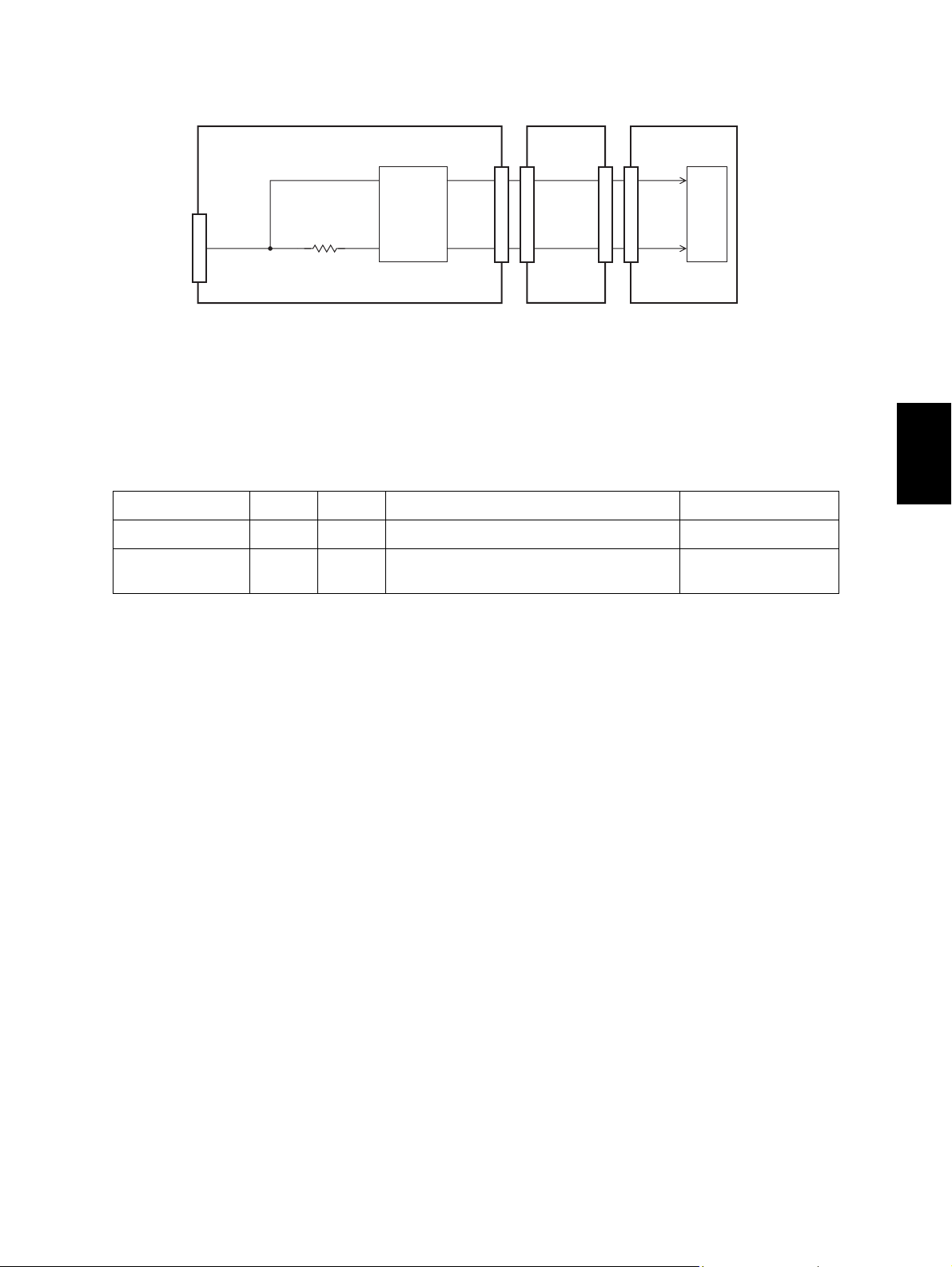
EU/AU/AS/C models
NCU board FAX board
19
8
20
7
Line
4
CN3
1
IC2
Line current
detection
Lb
R26
IC
2
CN4
19
CN262
20
REVA1
REVB1
66
33
CN5
CN5
MAIN board
160
66
161
33
IC23
ASIC
Fig. 4-9
The line current detection circuit consists of the line current detection IC (IC2), ASIC (IC23) on the
MAIN board, and the other peripheral devices. It detects a dial tone and the hook status of the external
telephone from the current flowing through the line.
When a dial tone is input from the telephone line, current flows through the line. The line current detection IC sends REVA1 and REVB1 to the ASIC as pulse signals. This allows a dial tone to be detected.
Signal Name Type Active Description Destination
REVA1 I - Line 1 Current Detection Signal IC23
REVB1 I - Current Reverse Line 1 Current Detection
Signal
IC23
4
© 2006 - 2008 TOSHIBA TEC CORPORATION All rights reserved GD-1220/1221
ELECTRICAL CIRCUITS
4 - 9
Page 70

4.2.5 CI detection circuit
NA/TW models
FAX board MAIN board
3
CML1
327
CN9
CN262
CI1
6517
CN5
2765144
CN5
IC23
ASIC
162
Line
NCU board
+12V
4
Lb
CN10
La
3
RLY2
CML relay
112
1
9
43
10
0
1
0
ZD3ZD1 C1 R2
D52
Q51
AG
124
PC2
5VPS
R79
17
3
SG
Fig. 4-10
The CI detection circuit consists of the photocoupler (PC2), ASIC (IC23) on the MAIN board and the
other peripheral devices to detect a ring signal input from the telephone line.
The ASIC makes the CML1 signal become LOW to connect the CI detection circuit to the telephone
line.
When a ring signal is input from the telephone line, the photocoupler is repeatedly turned ON/OFF. This
allows the CI1 signal to become a pulse signal and input to the ASIC on the MAIN board, thereby
detecting the ring signal.
Signal Name Type Active Description Destination
CI1 I - Line 1 CI Detect Signal IC23
GD-1220/1221 © 2006 - 2008 TOSHIBA TEC CORPORATION All rights reserved
ELECTRICAL CIRCUITS
4 - 10
Page 71

EU/AU/AS/C models
NCU board FAX board
RLY3
+12V
CML relay
Line
CN3
121
4
Lb
3
La
1
4
0103
1
9
0
ZD3ZD2C8 R4
D2
Q4
AG
124
PC1
3
R35
3
5VPS
R34
17
Q5
SG
3
CML1
27
CN4
CN262
CI1
6517
CN5
MAIN board
2765144
CN5
162
IC23
ASIC
Fig. 4-11
The CI detection circuit consists of the photocoupler (PC1), ASIC (IC23) on the MAIN board and other
peripheral devices to detect a ring signal input from the telephone line.
The ASIC makes the CML1 signal become LOW to connect the CI detection circuit to the line. When a
ring signal is input from the telephone line, the photocoupler is repeatedly turned ON/OFF. This allows
Q5 to be turned ON/OFF and the CI1 signal to become a pulse signal and input to the ASIC on the
MAIN board, thereby detecting the ring signal.
4
Signal Name Type Active Description Destination
CI1 I - Line 1 CI Detection Signal IC23
© 2006 - 2008 TOSHIBA TEC CORPORATION All rights reserved GD-1220/1221
ELECTRICAL CIRCUITS
4 - 11
Page 72

4.2.6 Line monitor circuit
NA/TW models
Line
NCU board
Lb
4
CN10
La
3
+12V
9
4
RLY2
CML relay
FAX board
IC51
R71R67
Analog
T1
8
0
1
0
121
IC53
5
7
6
AG
R66
R68
Q51
AG
switch
1
3
0
R59
1
1
0
2
1
13
0
9,11 10
IC53
IC52
Speaker
112
267
6
3
4
15
14
TXOUT1
1
RXIN1
2
CN9
CN252
6
3
IC10
Analog
switch
IC10
CN264
353
1
2
SG
SP+
SP-
28,29
[
]
25,26
IC2
32
[29]
MODEM
MAIN board
[
]
SPKCLK
TONESEL 59
RING/TONE 2311
ATT3DB1 62
CML1 27
SPVOL0
SPVOL1
SPVOL2
25RING
25
59
23
CN5
CN5
62
27
58
58
57
57
24
24
IC53
A5
SoC
152
153
142
IC23
IC23
144
ASIC
151
ASIC
150
149
12
[2]
3
IC9
Analog
13
[4]
R273
14
[
R31
[2]
R272
15
[
R30
[5]
R271
12
[
R29
[1]
R270
1
[
R32
[12]
R268
5
[
R35
[15]
R267
[
2
R33
[14]
R266
[
R36
4
[
R37
[13]
AG
11
10
9
switch
15
9,10
]
]
]
]
]
]
]
]
Fig. 4-12
GD-1220/1221 © 2006 - 2008 TOSHIBA TEC CORPORATION All rights reserved
ELECTRICAL CIRCUITS
4 - 12
08/08
Page 73

EU/AU/AS/C models
FAX board
TXOUT1
1
1
RXIN1
2
27
CN4
CN9
CN252
6
6
3
3
IC10
Analog
switch
IC10
1
2
CN264
353
SG
SP+
SP-
28,29
[
]
25,26
IC2
32
[29]
MODEM
MAIN board
[
]
SPKCLK
TONESEL 59
RING/TONE 2311
ATT3DB1 62
CML1 27
SPVOL0
SPVOL1
SPVOL2
25RING
25
59
23
CN5
CN5
62
27
58
58
57
57
24
24
IC53
A5
SoC
152
153
142
IC23
144
ASIC
151
150
149
12
[2]
3
IC9
Analog
13
[4]
R273
[
14
R31
[2]
R272
[
15
R30
[5]
R271
[
12
R29
[1]
R270
[
1
R32
[12]
R268
[
5
R35
[15]
R267
[
2
R33
[14]
R266
[
R36
4
[
R37
[13]
AG
11
10
9
switch
15
9,10
]
]
]
]
]
]
]
]
Line
NCU board
4
Lb
CN3
3
La
+12V
4
9
1
RLY3
CML relay
T1
1
5
0
1
8
0
AG
12
IC6
21
IC3
Analog
IC6
Q4
AG
switch
R11
1
75
1
2
0
13
1
0
11 10
IC4
6
15
14
Speaker
Fig. 4-13
The line monitor circuit consists of the CML relay (NA/TW: RLY2, EU/AU/AS/C: RLY3), analog switch
(NA/TW: IC51, EU/AU/AS/C: IC3), analog switches (IC9, IC10) on the FAX board, ASIC (IC23) and
SoC (IC53) on the MAIN board, and other peripheral devices. It switches the telephone line path using
the analog switch and monitors the line status and ringer signal in the FAX transmission and reception
using the speaker connected to CN503 on the FAX board. It also switches the analog switch to output a
buzzer tone from the speaker.
4
The signal to be monitored is selected by switching the analog switch (IC9) according to TONESEL signal and RING/TONE signal which are output from the ASIC.
To monitor the line during the transmission and reception, the ASIC makes the CML1 signal become
HIGH to switch the analog switch and connect the line to the MODEM side.
For the line path switching control, refer to P. 4-4 "4.2.2 Line path switching control circuit".
The relation between the signal levels and monitoring signals is as follows.
Monitoring signal TONESEL RING/TONE
LINE Monitor LOW HIGH
Ringer/Alarm - LOW
© 2006 - 2008 TOSHIBA TEC CORPORATION All rights reserved GD-1220/1221
ELECTRICAL CIRCUITS
4 - 13
08/08
Page 74

The monitoring signal selected by IC9 is input to the analog switch (IC10) to select the output sound
volume. The sound volume is selected by switching IC10 according to the SPVOL0-2 signals output
from the ASIC and selecting an input resistance for the monitoring signal.
The relation between the signals and sound volume is as follows.
Sound volume SPVOL2 SPVOL1 SPVOL0
Max. (7) LOW LOW LOW
(6) LOW LOW HIGH
(5) LOW HIGH LOW
(4) LOW HIGH HIGH
(3) HIGH LOW LOW
(2) HIGH LOW HIGH
Min. (1) HIGH HIGH LOW
Silent (0) HIGH HIGH HIGH
The monitoring signal whose volume is controlled by IC10 is amplified by the OP amplifier (IC17), then
output to the speaker.
Signal Name Type Active Description Destination
TONESEL O H Line/Tone Selection Signal IC9
RING/TONE O H Ring/Tone Selection Signal IC9
SPVOL0-2 O H Speaker Volume Control Signals 0-2 IC10
* Values in [ ] are GD-1221 in case that the descriptions vary between GD-1220 and GD-1221.
GD-1220/1221 © 2006 - 2008 TOSHIBA TEC CORPORATION All rights reserved
ELECTRICAL CIRCUITS
4 - 14
08/08
Page 75

4.3 PC Boards
1) PWA-F-FAX-635 (GD-1220)
4
Fig. 4-14
© 2006 - 2008 TOSHIBA TEC CORPORATION All rights reserved GD-1220/1221
4 - 15
08/08
ELECTRICAL CIRCUITS
Page 76

2) PWA-F-FAX-678 (GD-1221)
3) PWA-F-NCU-631 (NAD, TWD, SAD)
Fig. 4-15
Fig. 4-16
GD-1220/1221 © 2006 - 2008 TOSHIBA TEC CORPORATION All rights reserved
ELECTRICAL CIRCUITS
4 - 16
08/08
Page 77

4) PWA-F-NCU-631 (MJD, AUD, ASD, CND)
4
Fig. 4-17
© 2006 - 2008 TOSHIBA TEC CORPORATION All rights reserved GD-1220/1221
4 - 17
ELECTRICAL CIRCUITS
Page 78

GD-1220/1221 © 2006 - 2008 TOSHIBA TEC CORPORATION All rights reserved
ELECTRICAL CIRCUITS
4 - 18
Page 79

5. INSTALLATION
5.1 Explanation to the Users
After installing the FAX unit, explain the following items to the user using the Operator’s Manual.
With the underlined items, actually demonstrate the operation.
Items to be explained
• Switches and control panel
- Summary of the control panel (FAX functions)
- After power is turned OFF, image data are kept in HDD.
• How to set originals
- Acceptable original size and scanning width
- How to insert originals:
Multiple originals placed on the RADF are scanned from the first page.
- Unacceptable originals
- How to set the mode (image quality) and density (contrast)
• Transmission method
- Manual transmission
- Monitor dialing
- Direct dialing (with the digital keys)
- Phone book dialing
- Delayed transmission
- Multi transmission
- Redialing
5
• Recording paper size
- Recording paper size
- How to change the recording paper size
• Automatic/manual reception
- How to switch the automatic and manual reception
- How the machine works and how to operate it when a FAX is received in these modes
• Other functions
- Memory reception (with the power kept ON)
- How to set the power saving mode
• Polling
- Polling operation
- How to operate the polling reception and transmission
- How the multi-polling reception works and how to operate it
• How to register addresses
- How to register new addresses in the Phone Book
- How to correct or erase the contents of the Phone Book
- Group registration in the phone book for the multi-transmission or multi-polling
• How to output lists
- How to output the TRANSMISSION JOURNAL and RECEPTION JOURNAL
© 2006 - 2008 TOSHIBA TEC CORPORATION All rights reserved GD-1220/1221
5 - 1
INSTALLATION
Page 80

GD-1220/1221 © 2006 - 2008 TOSHIBA TEC CORPORATION All rights reserved
INSTALLATION
5 - 2
Page 81

Page 82

 Loading...