

Toshiba GD 1080, GD 1090 Service Handbook

SERVICE HANDBOOK
FACSIMILE (FOR DP4500/3500)
GD1080/1090
Click the Navigation Pane button to open the overview area and
display bookmarks and thumbnails palettes.
Click the Bookmarks to open the Contents and display Bookmarks
created for the document. Click a bookmark's name to go to the
Page marked by that bookmark.
Click the Thumbnails to open the overview area and display
thumbnail images of each document page. Click a thumbnail to go
to the Page marked by that thumbnail.
Copyright TOSHIBA TEC CORPORATION 2001
ALL RIGHTS RESERVED
GENERAL PRECAUTIONS REGARDING THE INSTALLATION
AND SER VICE FOR DP4500/3500 AND GD1080/1090
The installation and service should be done by a qualified service technician.
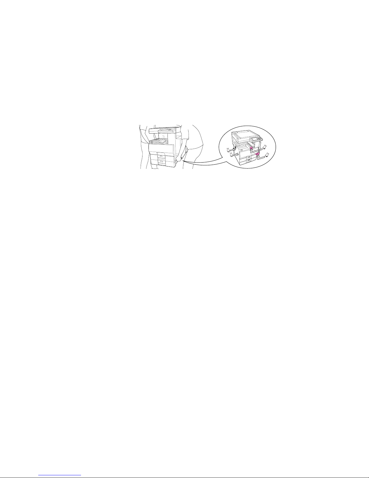
1. T ransportation/Installation
• When transporting/installing the copier, employ two persons and be sure to use the positions as
indicated below .
The copier is quite heavy and weighs approximately 73kg (161lb), therefore pay full attention when
handling it.
• Be sure to use a dedicated outlet with AC 115V or 120V/15A (220V, 230V , 240V/10A) or more f or
its power source.
• The copier must be grounded for saf ety.
Never g round it to a gas pipe or a water pipe.
• Select a suitable place for installation.
Av oid excessive heat, high humidity, dust, vibration and direct sunlight.
• Also provide proper ventilation as the copier emits a slight amount of ozone .
• To insure adequate working space for the copying operation, keep a minimum clearance of
80 cm (32”) on the left, 80 cm (32”) on the right and 10 cm (4”) in the rear.
2. Service of Machines
• Basically, be sure to turn the main switch off and unplug the power cord during service.
• Be sure not to touch high-temperature sections such as the exposure lamp, the fuser unit, the
damp heater and their periphery.
• Be sure not to touch high-voltage sections such as the chargers, high-voltage transformer, IH
control circuit, exposure lamp control inverter, inverter for the LCD backlight and power supply
unit. Especially, the board of these components should not be touched since the electirc charge
may remain in the condensers, etc. on them even after the power is turned OFF.
• Be sure not to touch rotating/operating sections such as gears, belts, pulleys, fan, etc.
• Be careful when removing the covers since there might be the parts with very sharp edges underneath.
• When servicing the machines with the main switch turned on, be sure not to touch live sections
and rotating/operating sections. Av oid exposure to laser radiation.
• Use suitable measuring instruments and tools.
• Av oid exposure to laser radiation during servicing.
− Av oid direct exposure to the beam.
− Do not insert tools, parts, etc. that are reflective into the path of the laser beam.
− Remove all watches, rings, bracelets , etc. that are reflective.

3. Main Service Parts for Safety
• The breaker , door switch, fuse, thermostat, thermofuse, thermistor, etc. are particularly important
for safety. Be sure to handle/install them properly.
4. Cautionary Labels
• During servicing, be sure to check the rating plate and the cautionary labels such as “Unplug the
power cord during service”, “Hot area”, “Laser w arning label” etc. to see if there is any dirt on their
surface and whether they are properly stuck to the copier.
5. Disposition of Consumable Parts/Packing Materials
• Regarding the recovery and disposal of the copier, supplies , consumable parts and packing materials, it is recommended to follow the relevant local regulations or rules.
6. When parts are disassembled, reassembly is basically the reverse of disassembly unless
otherwise noted in this manual or other related documents. Be careful not to reassemble
small parts such as screws, washer s, pins, E-rings, star washers in the wr ong places.
7. Basically , the machine should not be operated with an y parts removed or disassembled.
8. Precautions Against Static Electricity
• The PC board must be stored in an anti-electrostatic bag and handled carefully using a wristband,
because the ICs on it may become damaged due to static electricity.
Caution: Before using the wristband, pull out the power cor d plug of the copier and make
sure that there are no uninsulated charged objects in the vicinity .
Caution : Dispose of used batteries and RAM-ICs including lithium batteri es
according to the manufacturer’s instructions.
Attention : Se débarrasser de batteries et RAM-ICs usés y compris les batteries en
lithium selon les instructions du fabricant.
V orsic ht : Entsorgung des gebrauchten Batterien und RAM-ICs (inklusive
der Lithium-Batterie) nach Angaben des Herstellers.

1. ERROR CODES
2. SELF-DIAGNOSIS MODE
3. TROUBLESHOOTING
4. PRECAUTIONS FOR
INSTALLATION OF FAX UNIT
5. UPDATING THE FIRMWARE

I October 2000 © T OSHIBA TECGD1080/1090 CONTENTS
CONTENTS
1. ERROR CODES ......................................................................................................................... 1- 1
1.1 Transmission/Reception Journal and Error Code List.............................................................. 1- 1
1.2 Error Messages ..................................................................................................................... 1- 4
2. SELF-DIA GNOSIS MODE .......................................................................................................... 2-1
2.1 Test Mode (03) ....................................................................................................................... 2- 2
2.2 Adjustment Mode (05)............................................................................................................ 2- 4
2.3 Setting Mode (08) .................................................................................................................. 2- 6
2.4 Function Mode (13) ................................................................................................................ 2-7
2.5 Fax Clearing Mode (1*)........................................................................................................... 2-30
2.6 Setting the RDC Pass word..................................................................................................... 2-33
2.7 Automatic Order for Supplies ................................................................................................. 2-34
3. TROUBLESHOO TING ................................................................................................................ 3- 1
3.1 Flow Chart for Recommended Telephone Screening............................................................... 3- 2
3.2 Error Analysis Flow................................................................................................................3-5
3.3 Lists Required When Problem Has Occurred in the Field .......................................................3- 6
3.4 Other Information Required for Error Analysis ........................................................................ 3-11
4. PRECA UTIONS FOR INST ALLA TION OF FAX UNIT .................................................................4- 1
4.1 Installation of Fax Unit ........................................................................................................... 4- 1
4.2 Country/Region Code ............................................................................................................. 4- 2
5. UPDATING THE FIRMWARE ...................................................................................................... 5-1

October 2000 © TOSHIBA TEC 1 - 1 GD1080/1090 ERROR CODES
1. ERROR CODES
1.1 Transmission/Reception Journal and Error Code List
The transmission journal is shown below. The error code list and status code list are available in the
following pages. The reception journal is output in the same form.
TRANSMISSION JOURNAL TIME : MM-DD-YY TIME
TEL NO.1 : XXXXXXXXX
TEL NO.2 : XXXXXXXXX
NAME : X X X X X X X
NO. FILE NO. DATE TIME DURATION PGS TO DEPT MODE STATUS
001 001 12.01 09:00 00:55 2 ABCD G3 xxx OK xx
Status code
Error code

GD1080/1090 ERROR CODES 1 - 2 October 2000 © TOSHIBA TEC
Normal
Paper jam
Original jam
Door is open
Power failure
(Reset)
Polling error
Memory full
Line is busy
Security mismatch
in relay or mail box
transmission
Initial signal not
detected
Terminal constants
not compatible
Reception of DCN
(Phase B)
DCS/DTC not detected
Training error
CFR not detected
Image signal
carrier not detected
High speed signal
not detected
Image signal carrier
disconnected
1st EOL not detected
EOL not detected
Post message not
detected
Reception of DCN
Poor image quality
Image memory error
00
11
12
13
20
30
33
42
50
53
B0
B1
B2
B3
B4
B5
C0
C1
C2
C3
C4
D0
D1
D2
E0
Remove the jamming paper.
Remove the jamming document and retransmit it.
Close the doors securely and retransmit the document.
A power failure occurred during transmission or reception, and the transmission/reception data were lost. Attempt the transmission/reception again.
Communication was stopped by the FC key.
Polling was not performed because the polling document was not found. Check
the polling document on the other side and attempt the polling again.
The memory became full during reception. (The pages normally received are
printed out.) Check the remaining memory space and attempt the reception again.
Transmission is not made because the line is busy. Attempt the transmission
again. As the number of the redialings are increased, the possibility for successful transmission is increased.
Check your security code and system password of the other side as well as y our
own.
NSF/DIS cannot be detected. Check the receiver and attempt the transmission
again.
DIS/NSF that cannot be handled by the sender was received. The receiver received NSS/DCS other than those declared by DIS/NSF. Check the transmission/reception functions, and attempt the communication again.
DCN was received in the phase B.
DCS/DTC cannot be detected.
The sender performed fall-back but the transmission was not made. After the
reception of FTT, the receiver received a time-out or DCN. Adjust the transmitter
attenuator, link equalizer, etc. and retry the communication.
A training signal was sent out but CFR cannot be detected. Adjust the transmitter
attenuator, link equalizer, etc. and retry the transmission.
A carrier was not detected on the receiving side. Adjust the transmitter attenuator ,
link equalizer, etc. and retry the transmission.
High-speed signals were not detected on the receiving side. Adjust the tr ansmitter attenuator, link equalizer, etc. and retry the transmission.
Carrier disconnection was detected after the image signal was detected.
1st EOL was not detected after the high-speed signal was detected.
EOL cannot be detected on the receiving side. Or decoding is not possib le with MMR.
A post message cannot be detected. Retry the communication. MCF, RTP, RTN,
PIN and PIP cannot be detected on the sending side. MPS , EOM and EOP cannot be detected on the receiving side.
DCN was received.
Quality of the received image is poor. Retry the transmission.
Hardware is defective.
[A] Error code list
If an error has occurred during communication, an error code is indicated below “STATUS” on the
transmission/reception journal.
Take the appropriate action referring to the following list.
Error code Content Situation and corrective action
October 2000 © TOSHIBA TEC 1 - 3 GD1080/1090 ERROR CODES
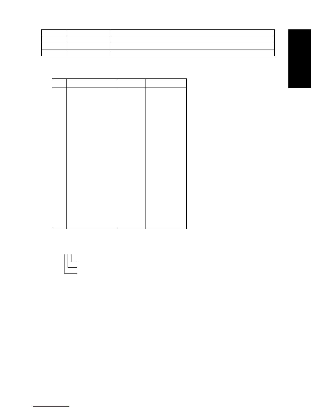
[B] Status code list
[Example of the indication of a status code]
522
MMR (encoding system)
8 x 15.4 (resolution)
14400 (transmission speed)
Mode Transmission speed Resolution Encoding system
0 2400 8 x 3.85 MH
1 4800 8 x 7.7 MR
2 7200 8 x 15.4 MMR
3 9600 JBIG
4 12000 16 x 15.4
5 14400
6 16800
7 19200
8 21600 300 x 300
9 24000
A 26400
B 28800
C 31200
D 33600
E
F
Error code Content Situation and corrective action
E8
F0
F1
HDD error
Software trouble
Hardware noise
Hardware is defective.
Software is defective.
Hardware is defective.

GD1080/1090 ERROR CODES 1 - 4 October 2000 © TOSHIBA TEC
Remarks
Message displayed only
during the memory input.
It is not displayed during
the memory reception
Job information is stored
in the memory when the
final retry is finished.
1.2 Error Messages
Error messages are not displayed for the background jobs (memory transmission and memory reception). See the reception/transmission report for the details of the errors.
If an original jam during the direct transmission or recording paper jam during printing occurred, error
messages are displayed like when original jam occurred in the copier.
Error messages and corrective actions
Error
Memory full
Line is busy
Initial signal not
detected
Ter minal constants not
compatible
Training error
CFR not detected
Image signal carrier
not detected
Image signal not
detected
EOL time-out
Post message not
detected
Poor image quality
Image memory error
Software overdrive
Hardware noise
Symptom
Communication was interrupted because the memory became full.
Redialing was attempted for the
specified number of times but the line
is still busy.
DIS is not detected
Received DIS unable to be handled
Received DCS which is beyond the
capability of the receiver
Fall-back is not made successfully.
Became time-out after FTT was
sent out
CFR (FTT) is not detected
Image signal carrier cannot be detected
High-speed signal cannot be received by the receiver
EOL timer exceeded by 13 seconds
Post message is not detected
TX: Received RTN/PIN/ERR
RX: Transmitted RTN/PIN/ERR
Memory is abnormal during the
memory communication
WDT communication terminated due
to software overdrive
Communication terminated due to
software overdrive caused by hardware noise
Message
MEMORY
OVERFLOW
COMMUNICATION
ERROR
COMMUNICATION
ERROR
COMMUNICATION
ERROR
COMMUNICATION
ERROR
COMMUNICATION
ERROR
COMMUNICATION
ERROR
COMMUNICATION
ERROR

October 2000 © TOSHIBA TEC 2 - 1 GD1080/1090 SELF-DIAGNOSIS MODE
2. SELF-DIAGNOSIS MODE
There are two types of the self-diagnosis mode for the fax operation.
• Mode 03, 05 and 08: Some items are added to the modes 03, 05 and 08 of the PPC self-diagnosis
function when the optional fax unit is installed.
• Mode 13 and 1*: These two modes are ne wly added to the machine when the fax unit is installed. Started
up by turning ON the power while pressing the specified keys are being pressed.
The followings are the modes which are added to (or extend) the PPC self-diagnosis function.
Turn ON the main switch (pow er) while pressing two digital keys (ex: “0” and “5”) simultaneously to enter
each mode.
Note : To finish the self-dia gnosis mode, turn the po wer OFF and then bac k ON.
Do not cancel the mode using the keys “0” and “9”.
(A malfunction may be caused because the start-up process is not performed properly.)
Keys to be pressed
to enter each mode
[0]+[3]+[POWER]
[0]+[5]+[POWER]
[0]+[8]+[POWER]
[1]+[3]+[POWER]
[1]+[✱]+[POWER]
Digital keys on the list output
screen (Do not enter the selfdiagnostic mode)
Function
Output check (modem test, dialing test, CML
test)
Adjustment of the various items
Setting the destination
Setting functions of the various items
Initialization of the various memory areas (user
registration area, system setting area, image
data area)
Outputs the protocol trace list, dump list and
function setting list
Mode
Test mode
Adjustment mode
Setting mode
Fax function mode
Fax clearing mode
Trace list output
mode
Display
100% C
test mode
100% A
test mode
100% D
test mode
100% F
test mode
100% CL
test mode
Fax screen
GD1080/1090 SELF-DIAGNOSIS MODE 2 - 2 October 2000 © TOSHIBA TEC
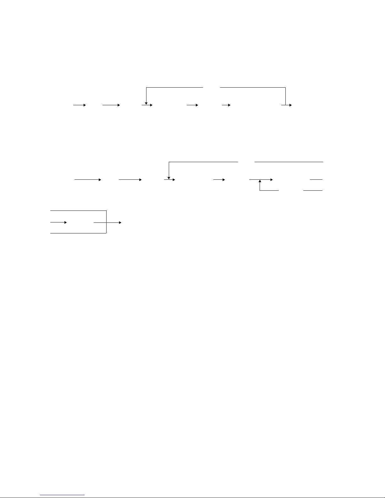
2.1 Test Mode (03)
The modem test output, dialing test output and CML test output are performed in the test mode (03).
(1) Modem test/CML test
[Operation procedure]
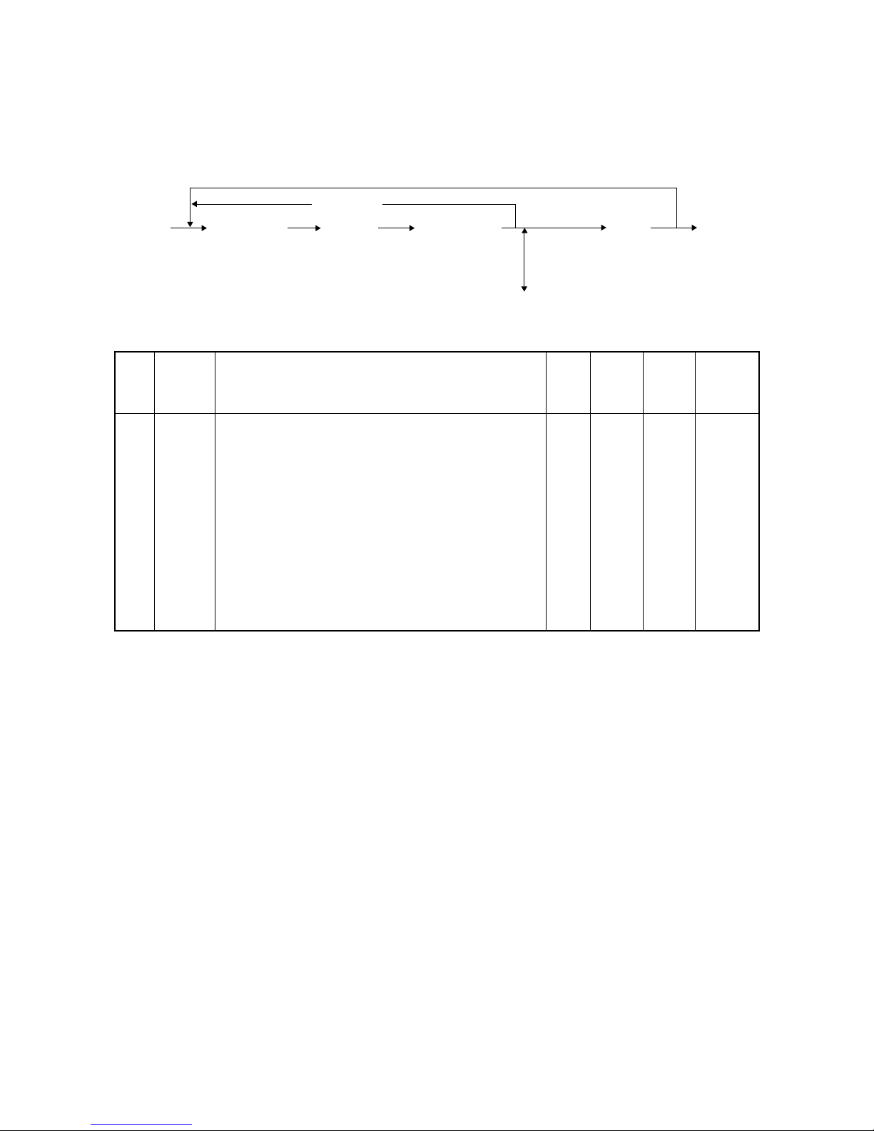
[0] [3] [FAX] ([FAX]) [Digital key] [START] Operation started [POWER] OFF
[POWER] (Switch line 1 and 2) (Code) (End)
(2) Dialing test
[Operation procedure]
[0] [3] [FAX] ([FAX]) [Digital key] [START] [Digital key]
[POWER] (Switch line 1 and 2) (Code) [START]
[START] [POWER] OFF
(End)
[C/S]
[C/S]

October 2000 © TOSHIBA TEC 2 - 3 GD1080/1090 SELF-DIAGNOSIS MODE
Test code list
Code
301
302
303
304
305
306
307
308
309
310
311
312
313
314
315
317
318
319
320
322
Element
Fax
Fax
Fax
Fax
Fax
Fax
Fax
Fax
Fax
Fax
Fax
Fax
Fax
Fax
Fax
Fax
Fax
Fax
Fax
Fax
Test
Modem test 2100 Hz
Modem test 14.4 kbps (V.17)
Modem test 9.6 kbps (V.29)
Modem test 4.8 kbps (V.27)
Modem test 300 BPS
Modem test 1850 Hz
Modem test 1650 Hz
Modem test 1100 Hz
Modem test 462 Hz
Modem test 1300 Hz
Modem test 33.6 kbps (V.34)
Modem test 28.8 kbps (V.34)
Modem test 24.0 kbps (V.34)
Modem test 16.8 kbps (V.34)
Dialing test 10PPS (Tested with the digital keys)
(The dial number corresponding to the key which w as pressed is k ept outputting
on the circuit. The pressed key is displayed on the control panel.)
Dialing test PB (Tested with the digital keys)
(The dial number corresponding to the key which w as pressed is k ept outputting
on the circuit. The pressed key is displayed on the control panel.)
Modem test 12.0 kbps (V.17)
Modem test 7.2 kbps (V.29)
Modem test 2.4 kbps (V.27ter)
CML test: Turning ON the CML relay
GD1080/1090 SELF-DIAGNOSIS MODE 2 - 4 October 2000 © TOSHIBA TEC
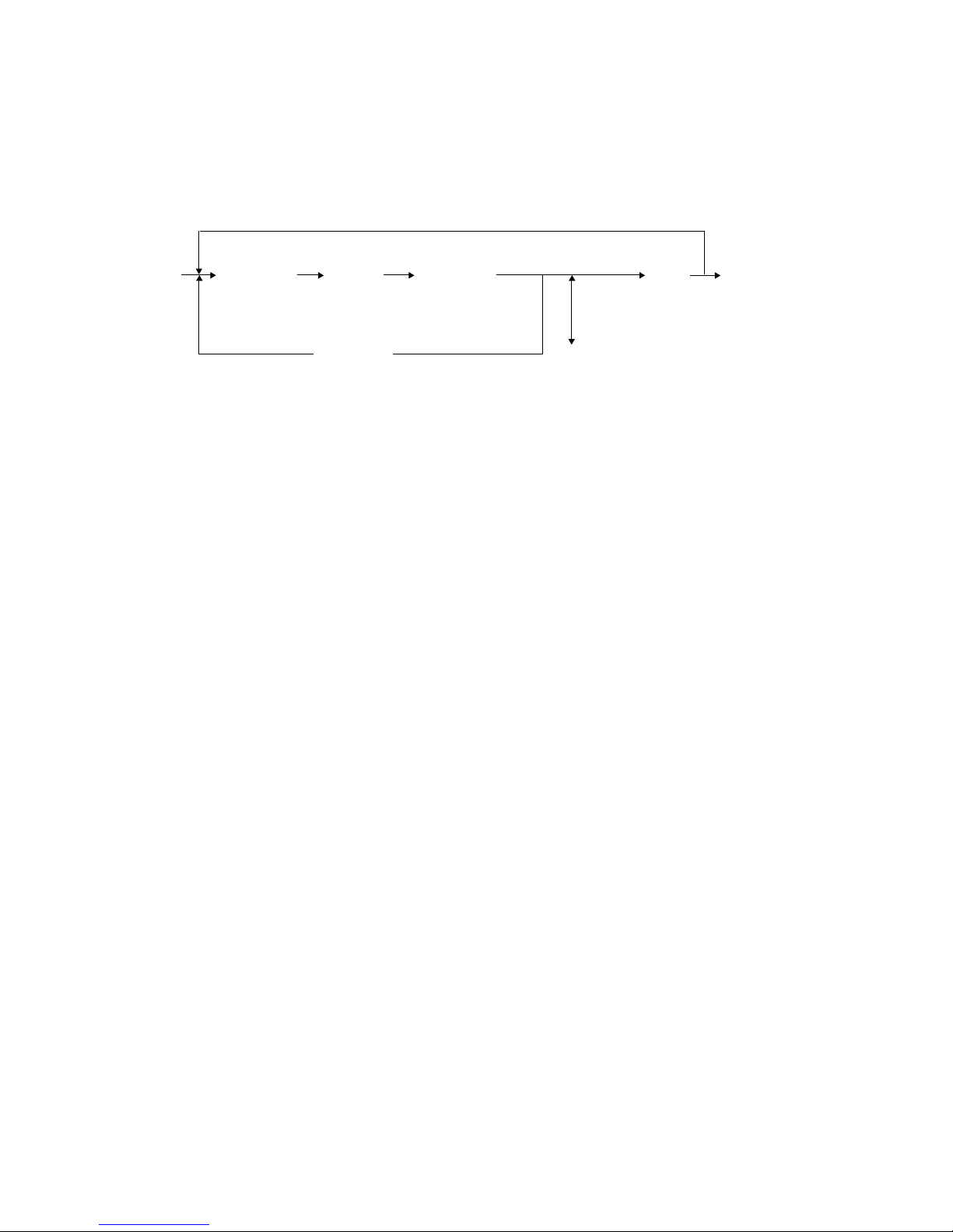
2.2 Adjustment Mode (05)
Parameter setting for the fax image processing is performed in the adjustment mode ‘05’.
(1) Setting parameters for the fax image processing
[Operation procedure]
[SET]
[0] [5] [Digital key] [START] [Digital key] or [POWER] OFF
[POWER] (Code) *[FC] key [INTERRUPT]
(Input adjustment value) (Save the value in the RAM)
[CANCEL] [C/S]
(In case the value is corrected)
* “–” can be entered with the [FC] key.

October 2000 © TOSHIBA TEC 2 - 5 GD1080/1090 SELF-DIAGNOSIS MODE
Code
700
701
702
710
714
715
719
720
724
725
729
Element
Density
Density
Density
Density
Density
Density
Density
Density
Density
Density
Density
Adjustment item
Adjustment of the threshold value for the digitization
Center value
Adjustment of the threshold value for the digitization
Lighter step value
Adjustment of the threshold value for the digitization
Darker step value
Manual-density fine adjustment
Error diffusion, Center value
Manual-density fine adjustment
Error diffusion, Center value
Manual-density fine adjustment
Error diffusion, Lighter step value
Manual-density fine adjustment
Error diffusion, Lighter step value
Manual-density fine adjustment
Error diffusion, Darker step value
Manual-density fine adjustment
Error diffusion, Darker step value
Auto-density fine adjustment
Error diffusion
Auto-density fine adjustment
Error diffusion
Mode
Fax
Fax
Fax
Fax
Fax
Fax
Fax
Fax
Fax
Fax
Fax
Image
quality
mode
Text
Text
Text
Photo
Text/
photo
Photo
Text/
photo
Photo
Text/
photo
Photo
Text/
photo
Default
120
20
20
128
128
12
20
25
20
128
128
Accept-
able
value
0~255
0~255
0~255
0~255
0~255
0~255
0~255
0~255
0~255
0~255
0~255
Adjustment codes for the image processing parameters
GD1080/1090 SELF-DIAGNOSIS MODE 2 - 6 October 2000 © TOSHIBA TEC
2.3 Setting Mode (08)
The destination is set in the setting mode (08).
[Operation procedure]
[CANCEL] [SET]
[0] [8] [Digital key] [ START] [Digital key] or [POWER]
[POWER] (Code) (Enter a value) [INTERRUPT] OFF
(Save the value in the RAM)
[C/S]
(In case the value is corrected)
Code
701
Element
Fax
Adjustment item
Destination
1: Asia 2: Australia 3: Hong Kong
4: U.S.A 5: Ger many 6: Great Britain
7: Italy 8: Belgium 9: Holland
10: Finland 11: Spain 12: Austria
13: Switzerland 14: Sweden 15: Denmark
16: Norway 17: Portugal 18: France
19: Greece 20: Poland 21: Hungary
22: Czech Rep. 23: Turkey 24:South Afr ica
Mode
Fax
Image
mode
ALL
Default
AU: 2
UC: 4
EUR: 5
Accept-
able
value

October 2000 © TOSHIBA TEC 2 - 7 GD1080/1090 SELF-DIAGNOSIS MODE
(2) Procedure to confirm the set value
[Operation procedure]
[SET]
[1] [3] [Digital key] [START] or [POWER] OFF
[POWER] (Code) [INTERRUPT]
(Set value cannot be changed)
2.4 Function Mode (13)
Various functions are set in the function mode (13).
(1) Procedure to set the functions
Enter a code using the digital keys and change the set value.
[Operation procedure]
[CANCEL] [SET]
[1] [3] [Digital key] [START] [Digital key] or [ POWER]
[POWER] (Code) (Enter a value) [INTERRUPT] OFF
(Save the value in the RAM)
[C/S]
(In case the value is corrected)
 Loading...