

Toshiba GD1060 User Manual

FA CSIMILE (FOR DP1600/2000/2500)
GD-1060
File No. 31100012

Copyright 2001
TOSHIBA TEC CORPORATION
GENERAL PRECAUTIONS REGARDING THE INST ALLA TION AND SERVICE FOR DP1600/2000/2500 AND GD-1060
The installation and service should be done by a qualified service technician.
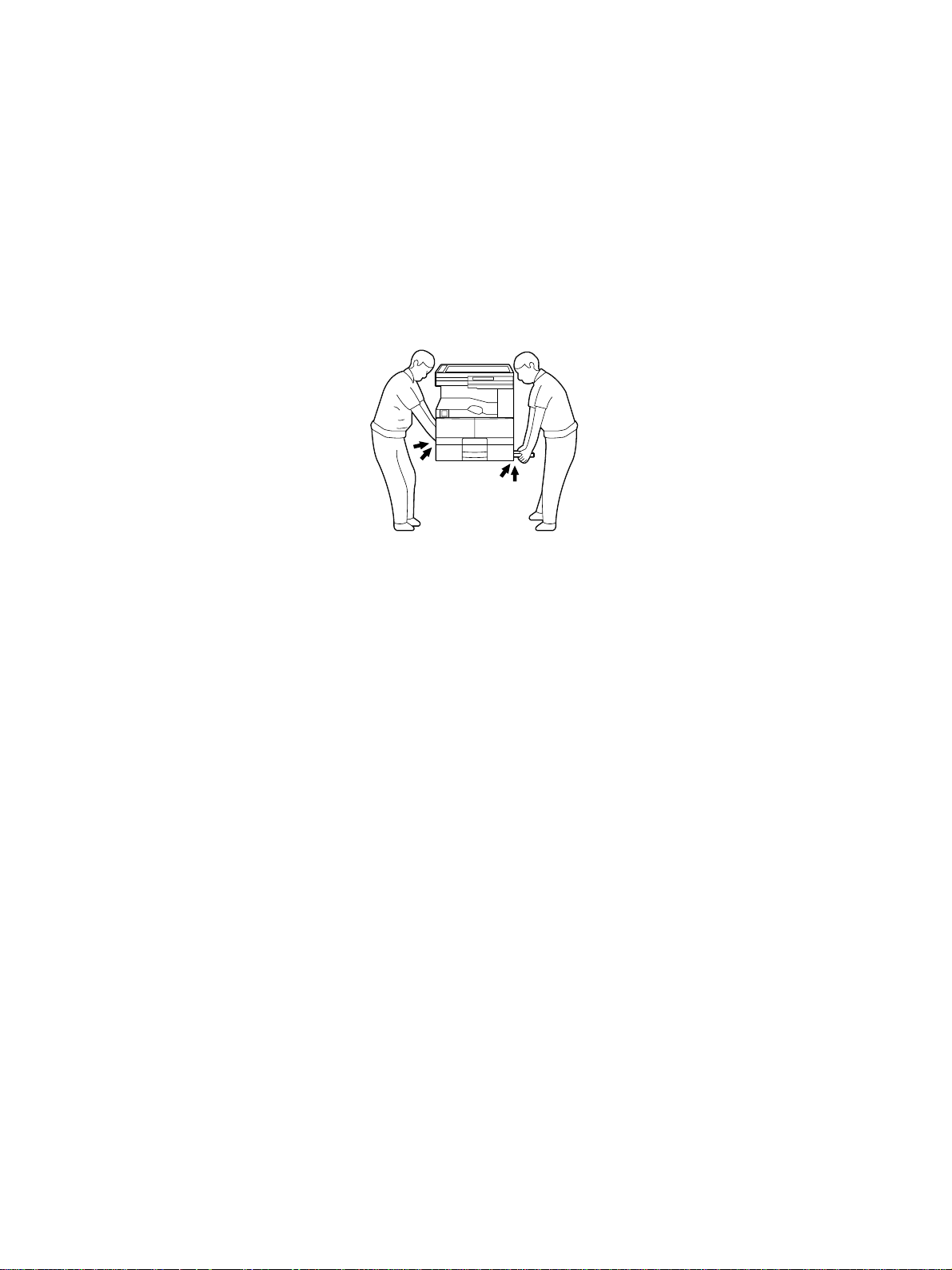
1. Transportation
• When transporting/installing the copier, employ two persons and be sure to use the positions as
indicated below .
The copier is fairly heavy and weighs approximately 50 kg (110 lb), therefore pay full attention
when handling it.
4 portions
2. Installation
• Be sure to use a dedicated outlet with AC 115 or 120V/15A (220V, 230V , 240V/10A) or more f or its
power source.
• The copier must be grounded for saf ety.
Never ground it to a gas pipe or a w ater pipe.
• Select a suitable place for installation.
Avoid excessive heat, high humidity, dust, vibration and direct sunlight.
• Also provide proper ventilation as the copier emits a slight amount of ozone.
• To insure adequate working space for the copying operation, keep a minimum clearance of 80
cm (32") on the left, 80 cm (32") on the right and 10 cm (4") in the rear.
• After having installed the copier, be sure to push the carrying handles into the copier .
3. Service of Machines
• Basically, be sure to turn the main switch off and unplug the power cord during service.
• Be sure not to touch high-temperature sections such as the exposure lamp, the fuser unit, the
damp heater and their periphery.
• Be sure not to touch high-voltage sections such as the chargers and the high-v oltage transformer .
• Be sure not to touch rotating/operating sections such as gears, belts, pulle ys , f ans, etc.
• When servicing the machines with the main switch turned on, be sure not to touch live sections
and rotating/operating sections. A v oid exposure to laser r adiation.
• Use suitable measuring instruments and tools.
January 2001 © TOSHIBA TEC GD-1060 GENERAL PRECAUTIONS

• Av oid e xposure to laser r adiation during servicing.
– Av oid direct e xposure to beam.
– Do not insert tools, parts, etc. that are reflective into the path of the laser beam.
– Remove all watches , rings, bracelets, etc. that are reflective.
4. Main Service Parts for Safety
• The breaker, door s witch, fuse, thermostat, thermofuse, thermistor, etc. are particularly important
for safety. Be sure to handle/install them properly.
5. Cautionary Labels
• During servicing, be sure to check the rating plate and the cautionary labels such as “Unplug the
power cord during service”, “Hot area”, “Laser w arning label” etc. to see if there is an y dirt on their
surface and whether they are properly stuck to the copier.
6. Disposition of Consumable Parts/Packing Materials
• Regarding the recovery and disposal of the copier, supplies, consumab le parts and packingm a terials, it is recommended to follow the rele v ant local regulations or rules.
7. When parts are disassembled, reassembly is basically the reverse of disassembly unless otherwise noted in this manual or other related documents. Be
careful not to reassemble small parts such as screws, washer s, pins, E-rings,
toothed washers in the wrong places.
8. Basically, the machine should not be operated with any parts removed or disassembled.
9. Precautions Against Static Electricity
• The PC board must be stored in an anti-electrostatic bag and handled carefully using a wristband,
because the ICs on it may become damaged due to static electricity.
Caution: Before using the wrist band, pull out the power cord plug of the copier and make
sure that there is no uninsulated charged objects in the vicinity.
Caution: Dispose of used batteries and RAM-ICs including lithium batteries according to the
manufacturer's instructions.
Attention: Se débarrasser de batteries et RAM-ICs usés y compris les batteries en lithium
selon les instructions du fabricant.
Vorsicht: Entsorgung des gebrauchten Batterien und RAM-ICs (inklusive der Lithium-Batterie)
nach Angaben des Herstellers.
GD-1060 GENERAL PRECAUTIONS January 2001 © TOSHIBA TEC

CONTENTS
1. FORM OF FAX OPTIONS OF DP1600/2000/2500 .................................................... 1-1
1.1 Fax Options (Necessary options to install the fax unit) .................................................... 1-1
2. SPECIFICATIONS • ACCESSORIES • OPTIONS ..................................................... 2-1
2.1 Specifications ................................................................................................................... 2-1
2.1.1 Scanning system................................................................................................... 2-1
2.1.2 Transmission system............................................................................................. 2-2
2.1.3 Telephone functions .............................................................................................. 2-3
2.1.4 Recording system ................................................................................................. 2-4
2.1.5 Software performance Table .................................................................................2-4
2.2 Specifications of LSU-related Performances.................................................................... 2-5
2.2.1 Recording paper size ............................................................................................ 2-5
2.2.2 Effective recording area ........................................................................................ 2-5
2.2.3 Print mode ............................................................................................................ 2-7
2.2.4 Recording paper selection algorithm and print algorithm ......................................2-7
2.2.5 Error processing.................................................................................................... 2-16
2.2.6 Limitations on reception print ................................................................................ 2-16
2.3 Accessories and cartoned parts....................................................................................... 2-17
2.4 Options..................................................................................................................... ........ 2-18
2.5 System List ...................................................................................................................... 2-19
3. GENERAL ................................................................................................................... 3-1
3.1 Main Functions................................................................................................................. 3-1
3.2 Overview .......................................................................................................................... 3-6
3.2.1 Front view.............................................................................................................. 3-6
3.2.2 Rear view .............................................................................................................. 3-7
3.2.3 Control panel for facsimile..................................................................................... 3-8
3.2.4 Function keys........................................................................................................ 3-12
3.3 Layout of Electrical Parts ................................................................................................. 3-15
January 2001 © TOSHIBA TEC 1 GD-1060 CONTENTS

4. DIALING AND COMMUNICATION PROCEDURE..................................................... 4-1
4.1 Line Connection and Mode Change Procedure................................................................ 4-1
4.1.1 Call to external telephone line ............................................................................... 4-1
4.1.2 Tx mode selecting procedure................................................................................ 4-2
4.2 Signal Format and Communication Procedure................................................................. 4-3
4.2.1 Network control signal format ............................................................................... 4-3
4.2.1.1 Network control signals........................................................................... 4-3
4.2.1.2 Signal format........................................................................................... 4-3
4.2.2 Communication by binary signals.......................................................................... 4-4
4.2.2.1 Binary procedure .................................................................................... 4-4
4.2.2.2 Binary signals ......................................................................................... 4-7
4.2.2.3 Frame structure of binary signals............................................................ 4-10
4.2.2.4 Training ................................................................................................... 4-12
4.3 High-speed Transmission Procedure................................................................................ 4-13
4.3.1 V.8/V.34 procedure ................................................................................................ 4-13
5. CIRCUIT DESCRIPTION ............................................................................................ 5-1
5.1 Block Diagram.................................................................................................................. 5-1
5.2 Flow of Image Signals...................................................................................................... 5 -2
5.2.1 Direct transmission ............................................................................................... 5-2
5.2.2 Memory transmission............................................................................................ 5-4
5.2.3 Reception.............................................................................................................. 5-6
5.3 FAX PWA ......................................................................................................................... 5-8
5.4 NCU PWA ........................................................................................................................ 5-9
5.4.1 Line path switching control circuit.......................................................................... 5-11
5.4.2 Dial pulse generation circuit .................................................................................. 5-13
5.4.3 Line current detect circuit...................................................................................... 5-15
5.4.4 CI detect circuit ..................................................................................................... 5-17
5.4.5 Line monitor circuit ................................................................................................ 5-19
5.5 OTK PWA ......................................................................................................................... 5-22
6. DISASSEMBLY AND REPLACEMENT...................................................................... 6-1
7. INSTALLATION ........................................................................................................... 7-1
7.1 Explanation to the User.................................................................................................... 7-1
GD-1060 CONTENTS 2 January 2001 © TOSHIBA TEC

1. FORM OF FAX OPTIONS OF DP1600/2000/2500
1.1 Fax Options (Necessary options to install the fax unit)
Several options can be supplied, which are necessary for extension, to extend the box function when you
install the fax unit. (Refer to 2.4 in detail)
January 2001 © TOSHIBA TEC 1 - 1 GD-1060 FROM OF FAX OPTIONS OF DP1600/2000/2500

2. SPECIFICATIONS • ACCESSORIES • OPTIONS
2.1 Specifications
2.1.1 Scanning system
• Scanning method CCD line sensor (Movable mirror type, Optical minification reading
method)
• Light source Xenon lamp
• Effective scanning area Standard mode
For NAD model
Horizontal scanning: Max. 280 mm (Ledger width)
Vertical scanning: Max. 432 mm (Ledger length)
For MJD, AUD, ASD, SAD, TWD, and CND models
Horizontal scanning: Max. 297 mm (A3 width)
Vertical scanning: Max. 420 mm (A3 length)
Long original mode
For NAD model
Horizontal scanning: Max. 280 mm (Ledger width)
Vertical scanning: Max. 1000 mm
For MJD, AUD, ASD, SAD, TWD, and CND models
Horizontal scanning: Max. 297 mm (A3 width)
Vertical scanning: Max. 1000 mm
Note: The maximum vertical scanning length is 700 mm when transmission is performed satisfying all of
the following conditions.
• The copier is in the long original mode.
• Direct transmission is performed.
• The original has the same width as of A3 or ledger.
• The receiving facsimile machine is capable of receiving originals with A4 only.
• Scanning density STANDARD: 8 dots/mm x 3.85 lines/mm
(Horizontal x Vertical) FINE: 8 dots/mm x 7.7 lines/mm
U-FINE: 16 dots/mm x 15.4 lines/mm
• Density control Automatic density mode and manual density selectable in 7 steps
January 2001 © TOSHIBA TEC 2 - 1 GD-1060 SPECIFICATIONS•ACCESSORIES•OPTIONS

• Speed of reading into memory For DP1600 series
(TTEC ITU-T#1 original, A4R 2.3 seconds (with platen)
STANDARD resolution) A4R 1.3 seconds (with ADF)
A4 1.8 seconds (with platen)
For DP2000/2500 series
A4R 1.8 seconds (with platen)
A4R 1.8 seconds (with ADF)
A4 1.4 seconds (with platen)
• Acceptable originals Type: sheet, book, and 3-dimensional object.
However, the automatic document feeder (option) only accepts
sheets of paper (Multi-sheet: 50 - 105 g/m2, or 13 - 29 lb/Single-
sheet: 105 - 127 g/m2, or 29 - 34 lb.), excluding carbon paper, pasted
sheets and stapled sheets.
Max size: A3/LD
• Capacity of originals For NAD model
LT, LT-R, ST-R, LG, Comp, LD : 50 sheets (with ADF)
LT, LT-R, ST-R, LG, Comp, LD : 100 sheets (with RADF)
For MJD, AUD, ASD, SAD, TWD, and CND models
A4, A4-R, B5, B5-R, A5-R, B4, Folio, A3: 50 sheets (with ADF)
A4, A4-R, B5, B5-R, A5-R, B4, Folio, A3: 100 sheets (with RADF)
2.1.2 Transmission system
• Line used Telephone line
• Communication mode Exclusive mode (CRP connection)
G3 mode
ECM (Error Correction Mode)
• Transmission time Less than 3 seconds (in the case of the memory transmission of a
TTEC ITU-T#1 original at 33.6 Kbps, STANDARD resolution, no
TTI, and JBIG (ECM))
• Numbers of files / jobs Transmission reservation jobs:
Max. 100 jobs (Memory Tx, Group Tx, Polling Rx, Relay Tx, Send-
ing to Mail Box)
Numbers of page at 1 memory transmission: Max. 999 sheets
GD-1060 SPECIFICATIONS•ACCESSORIES•OPTIONS 2 - 2 January 2001 © TOSHIBA TEC

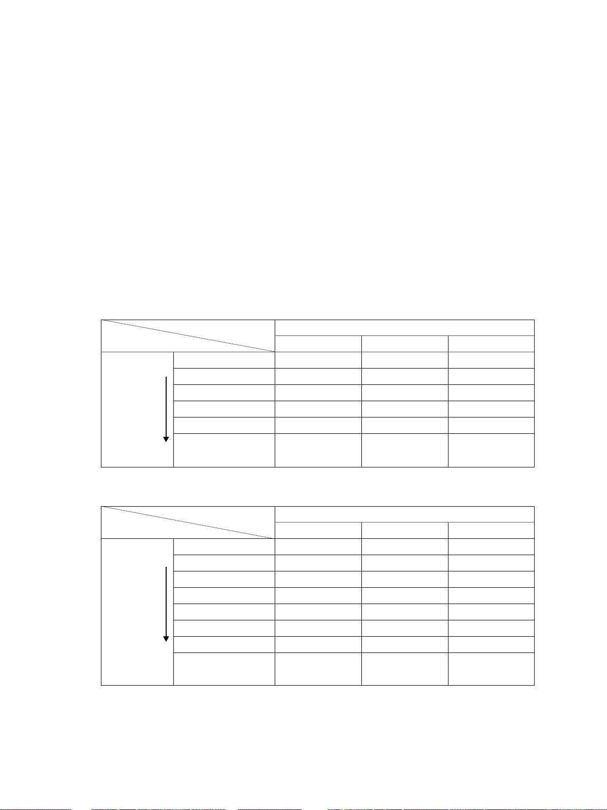
• Communication mode specifications
Horizontal scanning
density
Vertical scanning density
Data compression system
Transmission speed
(image signal)
Modulation system
(V.17/V.29/V.27ter/V.21)
Transmission speed
(image signal)
Modulation system (V.34)
Control signals FSK
Exclusive mode
(CRP call-out)
8 dots/mm,16 dots/mm
3.85 lines/mm
7.7 lines/mm
15.4 lines/mm
MH/MR/MMR/JBIG
14.4K/12.0K/9.6K
7.2K/4.8K/2.4K
—————
300 bps (V.21)
G3 mode
8 dots/mm,
16 dots/mm
3.85 lines/mm
7.7 lines/mm
15.4 lines/mm
MH/MR
14.4K/12.0K/9.6K/
7.2K/ 4.8K/2.4K
—————
300 bps (V.21)
ECM
8 dots/mm,
16 dots/mm
3.85 lines/mm
7.7 lines/mm
15.4 lines/mm
MH/MR/MMR/JBIG
14.4K/12.0K/9.6K/7.2K/
4.8K/2.4K
33.6K/31.2K/28.8K/
26.4K/24.0K/21.6K/
19.2K/16.8K/14.4K/
12.0K/9.6K/7.2K/4.8K/
2.4K
1200 bps (V.34)
300 bps (V.21)
Transmission control
Exclusive sequence
Conforming to T.30
Conforming to T.30
sequence
2.1.3 Telephone functions
• Dial-line function Pulse method - 10 pps
DTMF method
On/Off-hook dial function
Chain dial
• Keypad dial Max. 128 digits
• Re-dial Automatic / Manual
• Alphabet dial Max. 425 stations (OT75 + Abb300 + G50)
• Abbreviated dial Max. 300 stations (001 - 999)
• One touch dial Max. 75 stations
• Multi-address group dial Max. 50 groups, 375 stations / group
• Multi-address using [MULTI] key Max. 475 stations (OT75 + Abb300 + Keypad100)
• Chain dial Max. 128 digits (using Abb / OT / Keypad)
• Number of dialing Max. 100 jobs x 128 digits
January 2001 © TOSHIBA TEC 2 - 3 GD-1060 SPECIFICATIONS•ACCESSORIES•OPTIONS
2.1.4 Recording system
• Recording method Plain paper recording by laser beam printer
• Resolution Horizontal density: 16 dots/mm
Vertical density: 15.4 lines/mm
• Paper feeding Automatic feeding: Copier’s cassette 1 piece standard (expand-
able up to 4 pieces by installing optional cassettes)
PFU-optional (Stack height 60.5 mm, Equivalent to 550 sheets;
64 to 90 g/m2 (17 to 24 lb.))
PFP-optional (Stack height 60.5 mm, Equivalent to 550 sheets;
64 to 90 g/m2 (17 to 24 lb.))
LCF-optional (Stack height 137.5 mm, Equivalent to 1250 x 2
sheets; 64 to 80 g/m2 (17 to 22 lb.))
Bypass feeding (Stack height 16 mm, Equivalent to 100 sheets;
64 to 80 g/m2 (17 to 21 lb.))
2.1.5 Software performance Table
Item
Maximum
address
numbers of
diabl
Memory
capability
Maximum
numbers of
Sub. Item
Keypad dial
Abbreviated dial
Alphabet dial
One touch dial
Multi-address group
Multi-address using
[MULTI] key
ITU-T Mailbox/Relay box
Chain dial
Maximum number of
dialing
Transmission pix memory
Memory reception pix
memory
Tx reservation jobs
Numbers of page at 1
memory Tx
Limitation
128 digits
300 numbers (Maximum)
425 stations
75 numbers (Maximum)
50 groups (Maximum)
375 stations per 1 group
475 stations (Maximum)
100 boxes (Maximum)
Relay box: 50 end stations per
1 box (Maximum)
128 digits (Maximum)
100 jobs x 128 digits
5696 Kbyte : a)
5856 Kbyte : b) 160 Kbyte+a)
100 jobs (Maximum)
999 pages (Maximum)
Note
001-999
OT75+Abb300+G50
001-1999
OT75+Abb300+Key pad100
Using Abb. /OT / keypad
a)Approx. 490 pages *1
(*1 : ITU-T No.1/JBIG/STD)
b)Approx. 500 pages *1
(*1 : ITU-T No.1/JBIG/STD)
Memory Tx, Group Tx, Polling
Rx, Relay Tx, Sending to Mail
Box
GD-1060 SPECIFICATIONS•ACCESSORIES•OPTIONS 2 - 4 January 2001 © TOSHIBA TEC

2.2 Specifications of LSU-related Performances
2.2.1 Recording paper size
The following recording paper sizes can be used:
(For NAD model) : LD, LG, LT, LT-R, ST-R, COMP, A4, A4-R
(For MJD, AUD, ASD, SAD, TWD, CND models) : A3, A4, A4-R, A5-R, B4, FOLIO, LT, LT-R
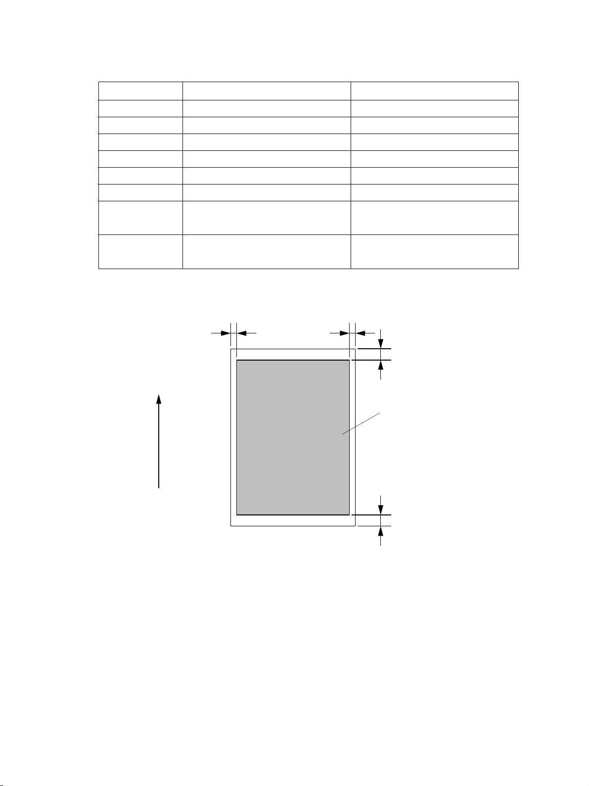
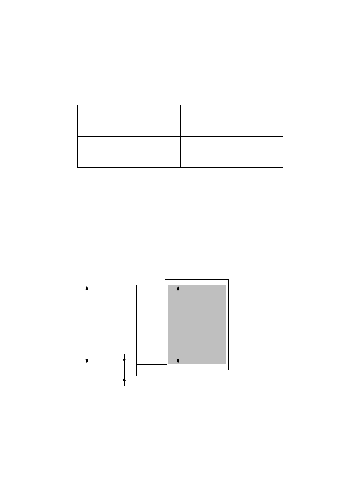
2.2.2 Effective recording area
a) Head : 4 mm (0.16 inch)
b) Foot : 4 mm (0.16 inch)
c) Effective Recording Limits:
1) For NAD model [Unit: mm (inch)]
Paper size Size (Horizontal x Vertical) Effective recording area
LD 279 x 432 275 x 424
(11 x 17) (10.8 x 16.7)
LG 216 x 356 212 x 348
(8.5 x 14) (8.3 x 13.7)
LT 279 x 216 275 x 208
(11 x 8.5) (10.8 x 8.2)
LT-R 216 x 279 212 x 271
(8.5 x 11) (8.3 x 10.7)
ST-R 140 x 216 136 x 208
(5.5 x 8.5) (5.4 x 8.2)
COMP 257 x 356 253.2 x 348
(10.125 x 14) (9.97 x 13.7)
A4 297 x 210 293 x 202
A4-R 210 x 297 206 x 289
January 2001 © TOSHIBA TEC 2 - 5 GD-1060 SPECIFICATIONS•ACCESSORIES•OPTIONS
2) For MJD, AUD, ASD, SAD, TWD, and CND models [Unit: mm (inch)]
Paper size Size (Horizontal x Vertical) Effective recording range
A3 297 x 420 293 x 412
A4 297 x 210 293 x 202
A4-R 210 x 297 206 x 289
A5-R 148 x 210 144 x 202
B4 257 x 364 253 x 356
FOLIO 210 x 330 206 x 322
LT 279 x 216 275 x 208
(11 x 8.5) (10.8 x 8.2)
LT-R 216 x 279 212 x 271
(8.5 x 11) (8.3 x 10.7)
Feed direction
2 mm
(0.08 inch)
Fig. 2-2-1
2 mm
(0.08 inch)
4 mm (0.16 inch)
Effective recording area
4 mm (0.16 inch)
02-02-01
GD-1060 SPECIFICATIONS•ACCESSORIES•OPTIONS 2 - 6 January 2001 © TOSHIBA TEC

2.2.3 Print mode
The machine provides various print modes to meet various requests from users, such as applicable
recording paper types, recording methods, etc.
2.2.4 Recording paper selection algorithm and print algorithm
A) Recording paper selection algorithm
Capable of identifying the above-mentioned recording paper size of a received image, this machine
prints on the recording paper of the same size as when sent, as a rule. If no recording paper of the
identified size is not available, it selects recording paper for printing according to the set mode. The
mode is set by using Func. 15 bit 3.
(1) Automatic reduction mode (Func. 15 bit 3 = 0, Default)
Selects recording paper on which the received document can be printed and prints on it.
(2) Reduction OFF mode (Func. 15 bit 3 = 1)
Selects recording paper on which the received document can be printed in a full size.
B) Print algorithm
A reception print image is basically printed on one page. Consequently, the algorithm of reception
print is in the order of same size print, discard extra, vertical reduction print, and divided print.
(Refer to the reception print flowchart.)
January 2001 © TOSHIBA TEC 2 - 7 GD-1060 SPECIFICATIONS•ACCESSORIES•OPTIONS
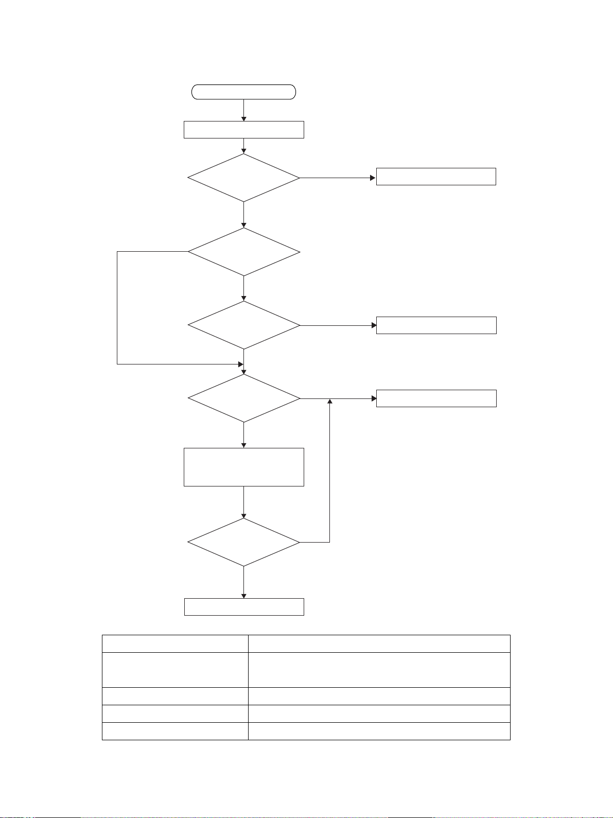
Reception print flowchart
Start
Receive FAX
Within effective
recording area ?
NO
Fraction discard
ON ?
Within
fraction discard length
range ?
Vertical reduction
ON ?
Calculate reduce ratio
γ from actual image data
NO
YES
NO
YES
YES
YES
NO
Full-size print
Fraction discard print
Divided print
γ within max.
reduce ratio ?
NO
YES
Vertical reduction print
Judgment parameter
Effective recording area Area excluding 4 mm from the top of recording paper
and 4 mm from the bottom.
Discard Function setting by user
Vertical reduction Function setting by user
Discard parameter Func. 15 bit 6, 7
GD-1060 SPECIFICATIONS•ACCESSORIES•OPTIONS 2 - 8 January 2001 © TOSHIBA TEC
(1) Discard printing
Func. 15 bit 2 permits selecting between ON and OFF of the option for discard extra.
Func. 15 bit 2 = 0 : OFF
Func. 15 bit 2 = 1 : ON (Default)
Func. 15 bits 6 and 7 allow the discard parameter to be set.
Func. 15 (Default Setting bit 2 = 0, bit 6 = 1, bit 7 = 0)
bit 2 bit 6 bit 7 Discard parameter
0 X X Discard OFF
1 0 0 0 mm (Discard OFF)
1 1 0 10 mm
1 0 1 17 mm
1 1 1 34 mm
• When the option for discard extra is ON:
When the length of the received document in the feed direction exceeds the effective recording
area and the part exceeding one page is within the discard parameter, printing takes place with
the exceeding part discarded. When the length of the received document in the feed direction
exceeds the discard parameter range and is within the reduction range of the maximum reduce
ratio, vertical reduction print takes place. When it is not within the reduction range of the maxi-
mum reduce ratio, divided print takes place. The discard extra takes preference over the vertical
reduction print.
Rcv. doc. Rcd. paper
A
A
A: Effective recording area
B: Record data length outside
effective recording area
B
If the length of B is less than the set discard parameter, B is discarded.
• When the option for discard extra is OFF:
The vertical reduction takes preference without performing discard extra print.
January 2001 © TOSHIBA TEC 2 - 9 GD-1060 SPECIFICATIONS•ACCESSORIES•OPTIONS
(2) Vertical reduction print
Func. 15 bit 5 permits selecting between ON and OFF of the option for Vertical reduction print.
Func. 15 bit 5 = 0 : OFF
Func. 15 bit 5 = 1 : ON (Default)
• When the option for Vertical reduction print is ON:
When the length of the received document in the feed direction exceeds the effective recording
area, the feed length is reduced in an appropriate reduce ratio and then the received document
is printed on one sheet of recording paper.
The following two patterns of maximum reduce ratio are available according to the setting of
Func. 15 bit 1.
Func. 15 bit 1 = 0 : Max. reduce ratio 90 % → The reduce ratio settings of 95% and 90 % are
valid.
Func. 15 bit 1 = 1 : Max. reduce ratio 73 % → The reduce ratio settings of 95 %, 90 %, 86 %,
80%, 83 % and 73 % are valid.
• When the option for vertical reduction print is OFF:
When the length of the received document in the feed direction exceeds the effective recording
area, divided print takes place.
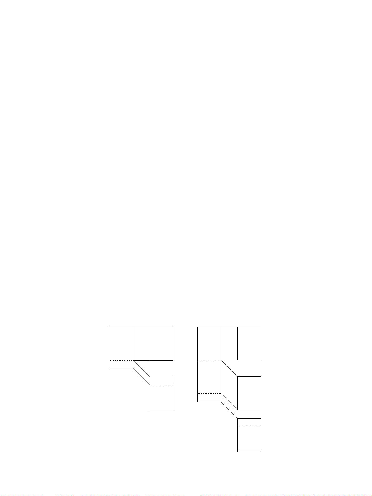
(3) Divided print
When received data cannot be recorded on one sheet, even if reception reduction and reception
discard are carried out, the recorded data is divided in the vertical direction and printed on two or
more sheets with maximum length set up in the copier, without reduction.
If a long original with length of 216 mm which cannot be recorded on one B4 sheet with the
maximum reduction is received, when A4, B4, and A5 paper is loaded in the first, second, and
third cassettes, respectively, for example, the maximum recording paper (B4) is selected and
received data is divided and printed on two or more sheets without reduction (see Table 5-2-2).
Ex.1 Divided into two sheets Ex.2 Divided into three sheets
GD-1060 SPECIFICATIONS•ACCESSORIES•OPTIONS 2 - 10 January 2001 © TOSHIBA TEC
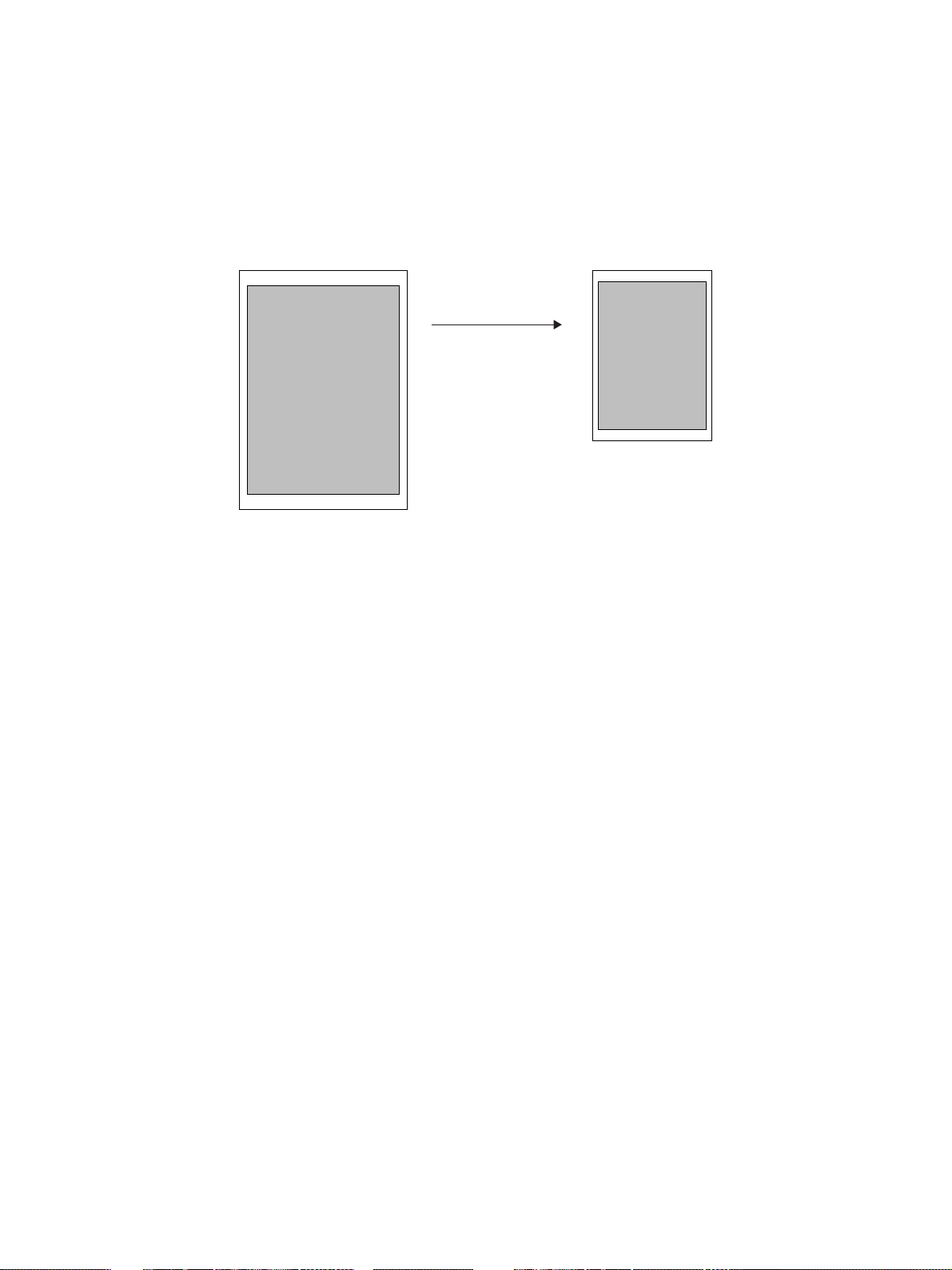
(4) Similar reduction print
When recording paper of the same size as that of the received document is not available due to
running out of paper or no paper is available to cover the received document, the received docu-
ment is similarly reduced and printed on recording paper smaller than the received document.
Ex.1 To print A3-size received document on an A4-R sheet because of running out of paper.
Similar reduction
A
A
B
B
C
C
A4-R
A3
(5) Rotation print
When recording paper of the same size as that of the received document exists but the orienta-
tions are different on those sheets, the received document is rotated by 270 degrees before being
printed. The rotation function is performed after discard extra, reduction or dividing processing.
The rotation function is valid for received documents of A4, LT, A5, and ST-R sizes.
(6) Printing with no recording paper
When recording paper has run out during printing, printing takes place on another printable re-
cording paper starting from the next page, if available. However, if recording paper has run out in
the middle of divided print, reprinting takes place on another recording paper starting from the
first one of the divided pages. (The same operation is done when recording paper of the same
size is set in a different paper cassette.)
For the selection order of recording paper, refer to Table 2-2-1.
January 2001 © TOSHIBA TEC 2 - 11 GD-1060 SPECIFICATIONS•ACCESSORIES•OPTIONS
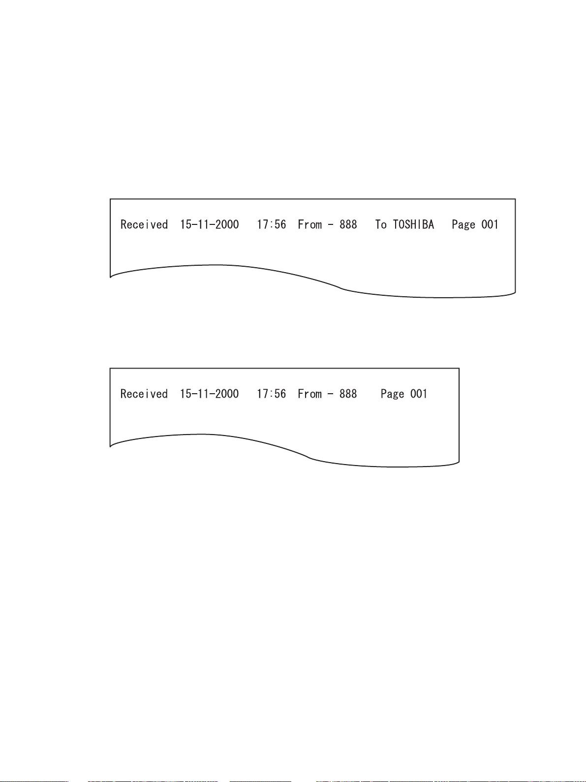
(7) RTI
When printing a received document with the RTI setting ON, RTI is printed on each page but RTI
is printed on the first page only in the case of divided print.
(ON or OFF of RTI is possible by means of the user setting. Default: OFF)
RTI is created for the LT or A4-R width. When printing RTI on A5, B5 and ST-R smaller than those
sheets, the information to be printed is reduced to a printable length.
• LT size or up
• A5, B5, ST-R
GD-1060 SPECIFICATIONS•ACCESSORIES•OPTIONS 2 - 12 January 2001 © TOSHIBA TEC
(8) Received document and selection of recording paper
The procedure for selecting recording paper handled by this machine is briefly described below.
Recording paper for reception print is selected according to the print recording paper range and
priority as listed in Table 2-2-1. A printable print recording paper range is selected according to
the scanning width and feed length of the received document. A print recording paper range is
selected by taking the discard length and feed reduce ratio into consideration.
Shown is an example where an EU model is used, the discard parameter is 10 mm, the feed
reduce ratio is max. 75 %, the scanning width of the received image is A4, the number of lines
received is STD or 2000 lines. Since the scanning width is A4, the recording paper range to be
selected is one of A5R, A4R, FOLIO, B4 and A3.
Since 2000 lines are converted to 519 mm, a feed length to allow 390 mm to be printed on one
page with a max. reduce ratio of 75 % is selected. The recording paper length of A4 is 297 mm,
the recording paper length of B4 is 364 mm, and the recording paper length of A3 is 420 mm.
Therefore, an A3 paper range covering 390 mm is selected. After an A3 range is selected, record-
ing paper is selected according to the priority in Table 2-2-1, followed by printing.
(Recording paper range selection for NAD model)
Scanning
216 mm 256 mm 303 mm
ST (140 mm) ST-R COMP LT
LT (216 mm) LT-R COMP LT
LT-R (279 mm) LT-R COMP LD
Feed length
LG/COMP (356 mm) LG COMP LD
LD (432 mm) LD LD LD
Long original LT (long) COMP (long) LD (long)
(over 432 mm)
(Recording paper range selection for MJD, AUD, ASD, SAD, TWD, CND models)
Scanning width
216 mm 256 mm 303 mm
A5 (148.5 mm) A5-R B5 A4
B5 (182 mm) A4-R B5 A4
A4 (210 mm) A4-R B4 A4
A4-R (297 mm) A4-R B4 A3
Feed length
FOLIO (330 mm) FOLIO B4 A3
B4 (364 mm) B4 B4 A3
A3 (420 mm) A3 A3 A3
Long original A4 (long) B4 (long) A3 (long)
(over 421 mm)
* When there is no recording paper which received data can be printed on one sheet of, the maxi-
mum paper loaded in the copier is selected and data is divided and printed on two or more sheets
without reduction (see table 5-2-2).
January 2001 © TOSHIBA TEC 2 - 13 GD-1060 SPECIFICATIONS•ACCESSORIES•OPTIONS
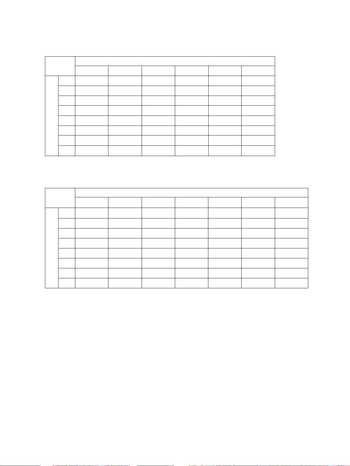
Table 2-2-1 Selection of recording paper
For NAD model
Recording paper range
LT-R LT LG COMP LD ST
1LT-R LT LGCOMPLDST-R
2LT *3LT-R
*3
COMP
3LG LD LD *2LT-R
4 A4-R LG
5 A4
6 COMP
*3
*2
7LD *2COMP
Priority of recording paperPriority of recording paper
8ST-R *1ST-R
*2*3
A4 LT
*3
A4-R
*2*3
*1*3
LT- R LT
*3
A4-R A4-R
*3
A4
*1
ST-R
For MJD, AUD, ASD, SAD, TWD, and CND models
Recording paper range
A4-RB4A3A4A5FOLIOB5
*3
*2
LD
*1*3
LG
A4
ST-R
*1*3
*2
*1
COMP
*1
*1
*1
LT-R
*1*3
LT
LG
A4-R
A4
ST-R
*1*3
*1
*1
LT- R
LT
*3
LG
*1
*1
*1
A4-R
*3
A4
COMP
*2
LD
*2
1A4-RB4A3A4A5-R *3FOLIO B4
2 A4
*3
3 FOLIO A4-R
4 LT-R A4
5LT *3FOLIO
6 B4
7 A3
8 A5-R
*2
*2
*1
A3
LT-R
*1*3
LT
A5-R
*2
*1*3
*1
B4
*1
*1
*1
*1
A4-R
*1*3
A4
FOLIO
LT-R
*1*3
LT
A5-R
*1
FOLIO
*1
*1
*1
*3
A4-R
A3 A4
*2*3
*2*3
B4
LT LT
*3
LT-R
*1*3
A5-R
A4-R B4
*3
A3
FOLIO A4-R A3
LT-R A4
B4
A3
*3
*2
*2
LT- R LT
*3
LT
A5-R
*1 : Similar reduction possible.
*2 : Center printing when printing out to a size larger in the scanning direction.
*3 : Rotation processing.
*2
*2
*3
*1
A4
A4-R
*2*3
FOLIO
LT-R
A5-R
*2
*2*3
*2*3
*2
*2*3
*1*3
GD-1060 SPECIFICATIONS•ACCESSORIES•OPTIONS 2 - 14 January 2001 © TOSHIBA TEC
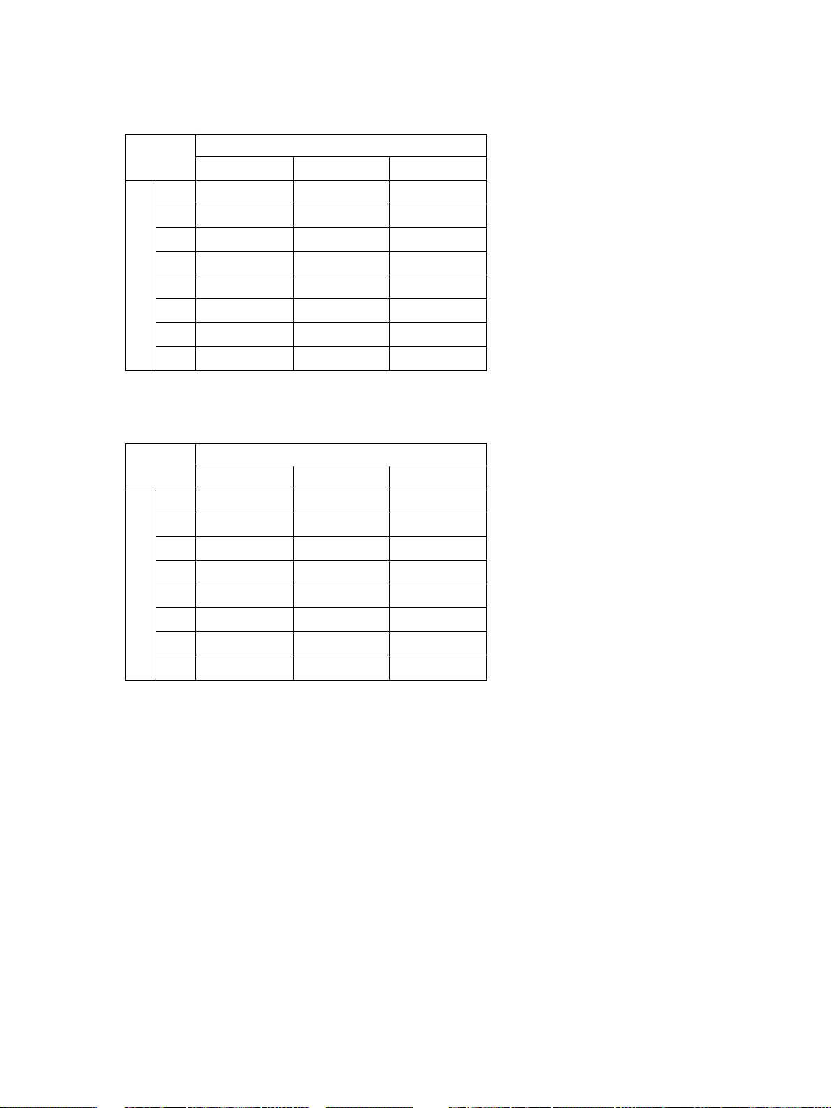
Table 2-2-2 Selection of recording paper (Long original)
For NAD model
Recording paper range
LT (long) COMP (long) LD (long)
1LD
2 COMP
*2
*2
3 LT- R LT- R
4LT *3LT
5LG LG *1LG
6 A4-R A4-R
7 A4
Priority of recording paper
8ST-R *1ST-R
*3
*2
LD
LD
COMP COMP
A4
*1
*1*3
*1
*1*3
*1
LT-R
*1*3
LT
A4-R
A4
ST-R
*1
*1*3
*1
For MJD, AUD, ASD, SAD, TWD, and CND models
Recording paper range
A4 (long) B4 (long) A3 (long)
1 A3
2 B4
*2
*2
3 A4-R A4-R
4 A4
*3
5 FOLIO FOLIO
6 LT- R LT- R
7LT *3LT
Priority of recording paper
8 A5-R
*1
*2
A3
B4 B4
*1
*1*3
A4
*1
*1
*1*3
*1
A5-R
A3
*1
A4-R
*1*3
A4
FOLIO
LT-R
*1*3
LT
A5-R
*1
*1
*1
*1
*1
*1
*1
*1 : Similar reduction possible.
*2 : Center printing when printing out to a size larger in the scanning direction.
*3 : Rotation processing.
January 2001 © TOSHIBA TEC 2 - 15 GD-1060 SPECIFICATIONS•ACCESSORIES•OPTIONS

2.2.5 Error processing
If paper has run out or a cassette has been pulled out, follow the procedure described below.
(1) If recording paper of a larger size has run out during communication:
For DIS redeclaration in the mode change procedure, declare the first recording paper size declared,
as it is.
(2) If a document has been received with recording paper of a larger size empty:
Declare the maximum value of the remaining recording paper or the attached cassette. Conform to
the setting of Func. 8 bit 4.
(3) If the cassette has been pulled out:
Assume A4 if none of the cassettes is left.
(4) If all paper has run out:
When the recording paper width capacity is recording paper and all paper has run out, assume A4.
(Same processing is done when only the recording paper of scan width less than 216 mm is set.)
2.2.6 Limitations on reception print
The following limitations are imposed on reception print.
(1) Reception print is not performed from the SFB.
(2) When the JSP is installed, reception print is always performed from the upper cassette.
After the upper tray becomes full, memory reception is performed. When the lower tray becomes full,
printing of received facsimile is possible.
(3) Even if the OCT is installed, it cannot be used during reception print.
(4) When the finisher is installed, it cannot be used.
(5) Even if the ADU is installed, it cannot be used.
(6) After the output tray is full, printout does not take place but delayed delivery is performed.
(7) When illegal paper is selected and printed on due to an operator mistake, the completion of printout is
assumed and no printout is performed again.
(8) The feed length of a received document is not limited. That is, printing is performed even if the re-
ceived document has several lines for printing. However, if the top lines are less than 5 lines, no
printing takes place. This also applies to multiple pages in divided print.
(9) Paper of the same size is present in multiple cassettes, printing takes place according to the following
cassette priority.
Order Cassette
1 Cassette selected by code 480 in system mode
2 1st cassette
3 2nd cassette
4 3rd cassette
5 LCF or 4th cassette
GD-1060 SPECIFICATIONS•ACCESSORIES•OPTIONS 2 - 16 January 2001 © TOSHIBA TEC

2.3 Accessories and cartoned parts
The following accessories and other parts come with the fax kit:
Accessory name Q’ty
Operator’s manual (for facsimile function) 1 pc.
Installation procedures 1 pc.
TEL LINE cable 1 pc.
SUPER G3 label 1 pc.
T/A label *1
Cartoned parts name Q’ty
Fax panel 1 pc.
Fax panel bottom cover 1 pc.
Fax PWA 1 pc.
NCU PWA 1 pc.
Battery 1 pc.
Fax panel harness 1 pc.
Ground wire 1 pc.
Locking support 1 pc.
Band 2 pcs.
BAIND screw M-3x8 4 pcs.
PAN Head screw M-3x8 2 pcs.
*1 The label that differs according to destination is packed.
January 2001 © TOSHIBA TEC 2 - 17 GD-1060 SPECIFICATIONS•ACCESSORIES•OPTIONS

2.4 Options
Extends the fax functions when the fax unit is installed.
Option Function DP1600 DP2000
DP2500
Original Cover Document cover KA-1600PC KA-1600PC
ADF Automatic document feeder MR-2012 MR-2012
MR-2012N MR-2012N
RADF Reverse automatic document feeder MR-3011 MR-3011
PFU Paper feed unit MY-1015 MY-1015
(2nd CASSETTE) A cassette, which can be installed under the copier. MY-1015N MY-1015N
PFP Paper feed pedestal KD-1009 KD-1009
(3rd CASSETTE) A cassette, which can be installed under the PFU. KD-1009N KD-1009N
CM Cassette module ----- MY-1017
(4th CASSETTE) The cassette module, which can be installed MY-1017N
in the PFP.
LCF Large capacity feeder ----- KD-1010
Large capacity feeder for A4 or LETTER size,
which can be installed under the PFU.
Note: If options, other than the ones listed above, are installed, the copier will operate; however the
options will not.
GD-1060 SPECIFICATIONS•ACCESSORIES•OPTIONS 2 - 18 January 2001 © TOSHIBA TEC
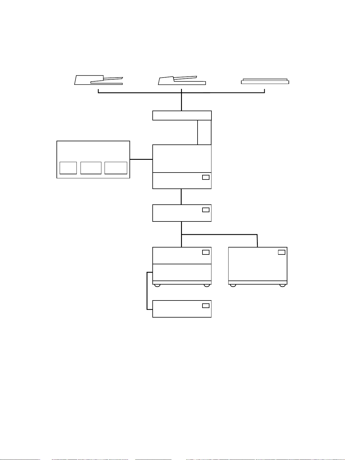
2.5 System List
Reverse automatic document feeder
GD-1060-NA/EU/AU/TW
FAX
board
(RADF)
MR-3011
Fax board kit
NCU
board
Operation
panel
Automatic document feeder
(ADF)
MR-2012, MR-2012N
DP1600/2000/2500
Paper feed unit (PFU)
MY-1015, MY-1015N
Original cover
KA-1600PC
Paper feed pedestal
(PFP)
KD-1009, KD-1009N
Cassette mdule (CM)
MY-1017, MY-1017N
(for DP2000/2500 series)
Large capacity feeder
(LCF)
KD-1010
(for DP2000/2500 series)
January 2001 © TOSHIBA TEC 2 - 19 GD-1060 SPECIFICATIONS•ACCESSORIES•OPTIONS

3. GENERAL
3.1 Main Functions
This machine has following features.
High-speed scanning:
The GD-1060-NA/TW/AU/EU scans one Letter (A4) size Original page in 1.4 seconds (line density 8
dots/mm x 3.85 lines/mm) and stores it into memory.
High-speed transmission:
The GD-1060-NA/TW/AU/EU uses a V.34 modem designed for 33,600 bps communications.
Multi-access:
Using the multi-access facility, multiple processes can be performed in parallel. Functions, such as
transmission reservation during reception, copying during memory transmission/ reception, etc. Maxi-
mizing the GD-1060-NA/TW/AU/EU’s high-speed scanning and multi-access capabilities provides
maximum office productivity and efficiency. Patterns of the multi-access are as follows:
(1) Scan to Memory during Memory Transmission
(2) Scan to Memory during Reception
(3) Scan to Memory during Substitute Reception
(4) Copying during Memory Transmission
(5) Reception during Copying
(6) Reception during Memory printing
(7) Reception during List printing
(8) Scan to Memory during Memory printing
(9) Scan to Memory during List printing
Laser recording on plain paper:
Recording is performed on fixed sizes of paper - Ledger, Legal, Letter, Letter-R, Statement,
Statement-R, Computer, A4, A4-R (to NAD model) or A3, A4, A4-R, A5-R, B4, FOLIO, Letter, Letter-
R (to MJD/AUD/ASD/SAD/TWD/CND models) - using a laser beam printer.
Halftone system:
Photographic images are clearly recorded by the 256 grayscales using the error diffusion method.
High resolution mode:
The GD-1060-NA/TW/AU/EU can transmit in ultra-fine mode (406 x 392).
January 2001 © TOSHIBA TEC 3 - 1 GD-1060 GENERAL

Image memory communication function:
Picture data can be stored in the image memory. For a delayed transmission, the picture data created
by scanning Originals is stored in the image memory and to be transmitted at the designated time.
Other memory functions include multi-address transmission, substitute reception, ECM communica-
tion, etc.
The memory contents will be retained by a backup battery for up to 2 hours if a power failure occurs.
The memory size is 5.7 MB.
75 one touch keys:
The remote party’s address data can be registered to a one touch key. Communication options can be
registered for each address. Some one touch keys also operate as direct function access keys. For
further details, refer to page 3-9.
300 abbreviated dial numbers:
300 abbreviated dial numbers can be assigned in the range from No. 001 to 999.
Alternate number dialing:
It is possible to assign two facsimile telephone numbers to one abbreviated dial number or one touch
dial key (one as the primary telephone number and the other as an alternate telephone number). The
facsimile first dials the primary telephone number, then redials if the line is busy until the redialing limit
count is reached. It will then begin to dial the alternate number. (Except for Relay/Mailbox/Confidential/
Polling)
Multi-address transmission function:
Transmissions of the same original to multiple addresses (up to 375 addresses) are possible using
one operation sequence, in which preset abbreviated dial numbers (300), and one touch dial keys (75)
can be used. When the multi-key is specified, key pad dialing of up to 100 locations, is also possible.
Multi-polling reception:
Polling receptions from multiple remote parties (up to 375 parties) are possible using one operation
sequence, in which preset abbreviated dial numbers (300), and one touch dial keys (75) can be used.
When the multi-key is specified, key pad dialing of up to 100 locations, is also possible.
Relay transmission request function:
The GD-1060-NA/TW/AU/EU can originate a relay transmission or serve as a relay station in relay
transmission transactions.
GD-1060 GENERAL 3 - 2 January 2001 © TOSHIBA TEC

Secure RX:
Secure RX allows reception to memory to secure Originals during unattended periods. The user can
select a specific time period and all day (24-hour) operation on selected days. The feature can be
activated and deactivated by using a 4-digit security code.
Memory transmission:
Allows you to dial the remote party while scanning the original in memory. The original page data is
cleared as the sending of each page is completed. Therefore, the memory is utilized effectively for
transmissions. A maximum of 100 jobs of memory transmission are possible.
Public fax box:
An original can be reserved in image memory to be polled by remote stations multiple times. One of its
merits is that any remote station (even one with a non-TOSHIBA facsimile) can poll such originals
without a password.
Program continuous polling:
By designating the starting interval, time, and day-of-week, an endless polling can be set. Once set,
polling receptions are repeated at the same time on the designated day-of-week.
Sub-address communication:
The GD-1060-NA/TW/AU/EU supports communication applications using sub-address (SUB/SEP/
PWD) commands conforming to ITU-T. Sub-address communication is possible by keypad dialing,
one touch key dialing, and abbreviated dialing using the sub-address settings in Comm. Options.
Security communication:
For transmissions, the facsimile checks if the telephone number of the remote party’s facsimile CSI
matches the number dialed on the unit itself. If it matches, the transmission will start. For receptions,
the facsimile checks if the telephone number of the remote party’s TSI matches any number assigned
to an abbreviated dial number or one touch key. If it matches, the reception will start. Thus transmis-
sions or receptions with any authorized party will be prevented at the earliest stage.
Substitute reception into memory:
When there is no paper remaining in the cassette(s), when a recording paper jam occurs, the toner is
empty, or printing is already in progress, the received data is stored into memory instead of being
output to recording paper. When the trouble is corrected, or the active printing job is completed, the
received data in memory will then be printed.
January 2001 © TOSHIBA TEC 3 - 3 GD-1060 GENERAL

Communication options:
If necessary, the function may be changed and options can be selected for page number, line monitor-
ing, turnaround polling, ECM communication and security transmission, etc.
Automatic dialing functions:
(1) Dialing with a time designated
Transmitting a original to a designated party at a designated time.
(2) Redialing
When an automatic dialing has been performed and the destination party is busy, redialing will be
repeated as many times as programmed with a certain time interval also programmed.
Cover sheet function:
This facsimile has a facsimile cover sheet preparation feature built in, allowing the operator to enter
the destination name, sender name at the time of the original transmission. This cover sheet also
allows image data, such as a company logo, to be included.
Account code:
By entering a different account code for each destination at the time of transmission, account codes
will identify when, for whom, and to whom a particular facsimile message was sent.
Department code:
Permits assigning 99 department codes to control access and track activity. These codes are set up
beforehand, and must be used to access machine functions.
Separator page function:
GD-1060-NA/TW/AU/EU has the feature which divide print jobs (received original) using separator
page. Also the customer can program the specified paper cassette for this function.
Auto supplies order
GD-1060-NA/TW/AU/EU has the feature which send a supplies order report to the programmed fac-
simile number automatically when the terminal detect toner end condition and drum low and/or end
condition.
List output:
This allows the operator to print data stored in the memory (reservation list, preset dial number lists,
function list, communication journal, transmission report, etc.).
GD-1060 GENERAL 3 - 4 January 2001 © TOSHIBA TEC
 Loading...