

Toshiba G3, GA932, NV Series Instruction Manual

6F8C1590
Unified Controller
nv Series
G3 I/O Adapter Module GA932
Instruction Manual

Notes
(1) The technical information provided herein describes typical operations and applications of the product and does not
guarantee the intellectual property rights or other rights of Toshiba or third parties nor allows license of its use.
(2) No part or the whole of this document may be reproduced without prior consent.
(3) The information herein may be changed in the future without notice.
(4) All possible measures have been taken to prepare the information herein. If you have any question, comment, or find
any error, please contact us.
PROSEC, TOSLINE, TC-net are trademarks or registered trademarks of Toshiba Corporation.
Ethernet is trademarks or registered trademarks of Fuji Xerox Corporation.
Device Net is registered trademarks or registered trademarks of ODVA (Open Device Net Vender Association Inc.)
PROFIBUS is registered trademarks or registered trademarks of PROFIBUS User Organization.
MODBUS is registered trademarks or registered trademarks of Schneider automation Inc.
MELSECNET is registered trademarks or registered trademarks of Mitsubishi Electric Corporation.
UNI-WIRE is registered trademarks or registered trademarks of KURODA Pneumatics Industries Ltd.
Temposonics is registered trademarks or registered trademarks of US company MTS Systems Corporation.
Absocoder is registered trademarks or registered trademarks of SG Corporation.
Unified Controller nv series G3 I/O Adapter GA932 Module Instruction Manual
i
Safety Precautions
On the product and this instruction manual, important information for safe and correct use to
prevent danger to the user and other people as well as property damage is described.
Understand the following information (signs and symbols) before reading the text, and follow
the described items.
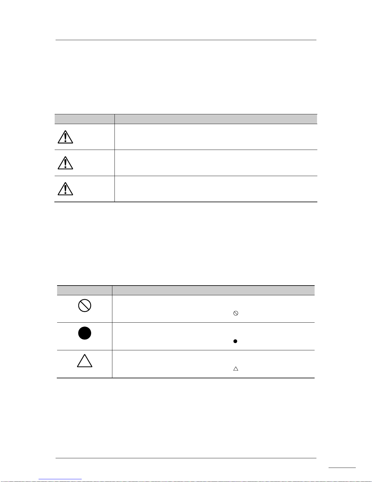
Description of signs
Sign Description
DANGER
Indicates that failure to avoid it will result in an immediate risk of
death or serious injury
(*1)
.
WARNING
Indicates that failure to avoid it will result in a risk of death or serious
injury
(*1)
.
CAUTION
Indicates that failure to avoid it will result in a risk of light or medium
injury
(*2)
or only property damage
(*3)
.
*1: A serious injury indicates loss of sight, injury, burns (high/low temperature), electric shock,
broken bones, or intoxication that will have aftereffects and require hospitalization or long-term
hospital visits for healing.
*2: An injury indicates an injury, burn, or electric shock that does not need hospitalization or
long-term hospital visits for healing.
*3: Property damage indicates consequential damage in terms of breakage of properties or materials.
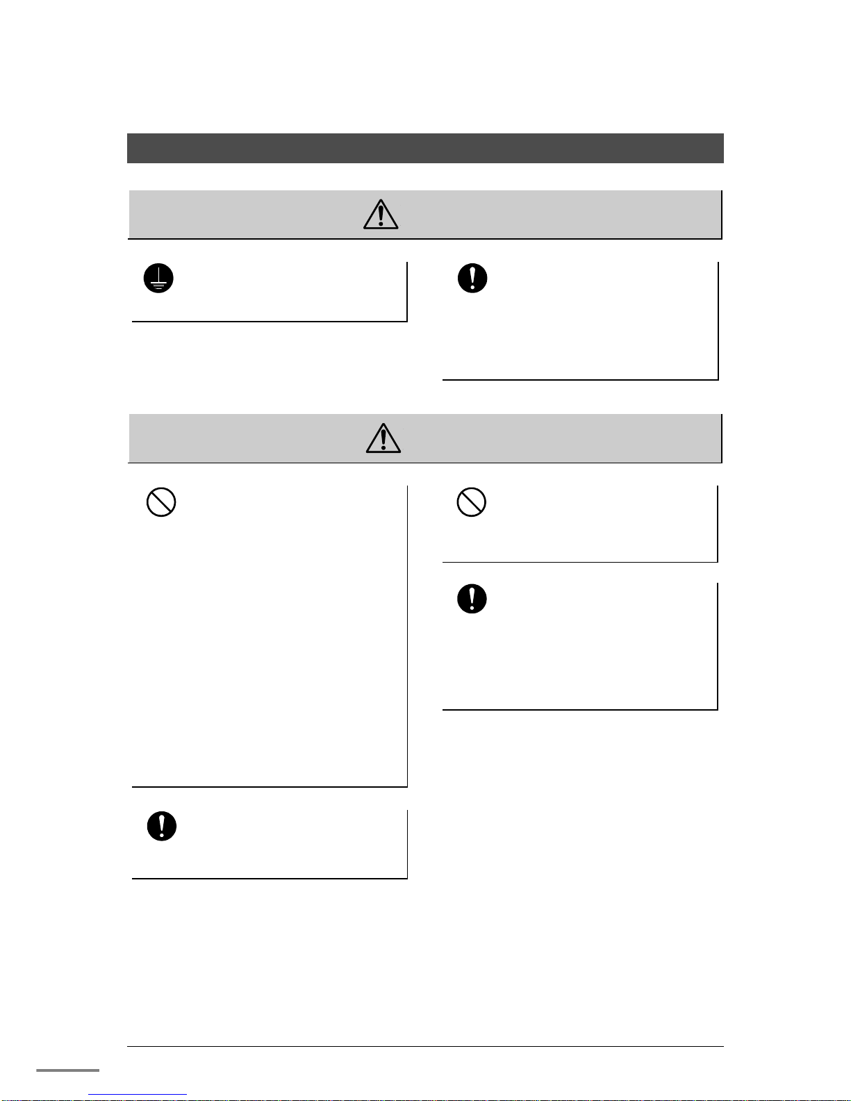
Description of symbols
Symbol Meaning
Prohibited
Indicates “Prohibition” or “You must not do”.
Specific details are indicated near the symbol with pictures and text.
Mandatory
Indicates “Mandatory Action” or “Do as indicated”.
Specific details are indicated near the symbol with pictures and text.
Warning
Indicates Warning.
Specific details are indicated near the symbol with pictures and text.
(Note) Descriptions of Prohibition, Mandatory Action, and Warning vary depending on the display on
the main unit.
6F8C1590
ii
1. Safety Precautions on Installation
WARNING
Ground
Ground the device.
Otherwise, it may cause an electric shock
or fire.
Mandatory
Configure the emergency stop
circuit and the interlock circuit
outside the controller.
Otherwise, this may cause human injury
or machine damage if the nv series has
a failure or malfunction.
CAUTION
Prohibited
Do not install, store, or use it
in the following environments.
・ A place with a lot of dust
・ A place with corrosive gases (SO2,
H2S) ore flammable gases
・ A place with vibrations and shocks
exceeding the allowed values
・ A place with condensations due to
rapid temperature changes
・ A place with low or high temperature
outside of the installation condition
・ A place with high humidity outside of
the installation condition
・ A place with direct sunlight
・ A place near equipment generating
strong radio waves or magnetic fields
It may cause accidents.
Mandatory
Install the device in a place where
maintenance and inspection can be
done easily.
Otherwise, it may cause accidents.
Prohibited
Do not block the ventilation
hole or air inlet/outlet.
It may cause fire or failure due to
overheat.
Mandatory
For installation and wiring of
the system, observe the
installation conditions and
methods described in this
document.
Otherwise, it may cause a fall, fire,
failure, or malfunction.
Unified Controller nv series G3 I/O Adapter (GA932) Module Instruction Manual
iii
2. Safety Precautions on Maintenance and Inspection
WARNING
Mandatory
When installing or removing
the module after wiring, turn
off the external power.
Otherwise, causing an electric shock
by touching conductive part.
CAUTION
Prohibited
Do not drop, crush, or apply
strong shocks to the device or
board.
It may cause failure.
Mandatory
Before touching the device or
board, touch a grounded
metal to discharge the static
electricity of your body.
Otherwise, it may cause malfunction or
failure due to static electricity.
Mandatory
Wipe off stain on the device,
module, or board with a soft
cloth.
For severe stain, use a wet cloth wrung
tightly.
Leaving them stained may cause wrong
decision or malfunction.
Mandatory
Place a board or module
removed from the unit or base
unit on a conductive mat or
conductive bag (used for a
backup board, etc.) on a
grounded table.
Otherwise, parts may be damaged due
to static electricity.
Prohibited
Do not use benzene or thinner
to remove stain on device,
module, or board.
It may cause deformation or
discoloration of the device panel,
module, or board.
6F8C1516
iv
3. Safety Precautions on Replacement of Life Limited Parts
WARNING
Mandatory
When replacing fuses, turn off
the switch of the device.
Otherwise, it may cause an electric
shock or fire.
4. Safety Precautions on Daily Use
WARNING
No touch
Do not touch the terminals of
the module and unit during
energization.
It may cause an electric shock.
Prohibited
Do not modify, repair,
disassemble, or adjust the
device, module, or board.
It may cause an electric shock, fire,
injury, or failure.
Upon faulty operation or failure, contact
Toshiba's branch office or service
offices.
Mandatory
For capacity, frequency,
voltage, and regulation,
please use a power supply
conforming to the
specification.
If not, it may cause damage of the
device, or fire due to overheat, as well
as not obtaining the original
performance of the device.
Mandatory
When the device temperature
rises abnormally or failure
occurs in the device, stop
using and turn off the power,
then contact to one of
Toshiba's service
representatives.
Using it as it is may cause fire due to
overheat.
Unified Controller nv series G3 I/O Adapter (GA932) Module Instruction Manual
v
CAUTION
Prohibited
Do not touch anything other
than the operation part
(setting switches inside the
module), such as the IC parts
and terminals, connectors,
and soldered surfaces inside
the module.
Doing so may result in electrostatic
breakdown of the ICs and LSIs, causing
failure. Also, an injury may occur due
to the ends of the part lead wires, or
burns may occur due to hot parts.
Prohibited
Do not disassemble or modify
the device or module.
It may cause malfunction or failure as
well as loss of safety of the device.
Prohibited
Do not forcefully bend, pull, or
twist the power cord and
cables.
It may cause breaks or heating.
Prohibited
Do not insert any metal inside
the module.
It may cause fire.
Mandatory
Use wireless communication
equipments as mobile phone,
smart phone and transceiver
at least 30cm away from the
module, transmission cables
and I/O cable.
It may cause malfunctions.
5.
Safety Precautions on Transportation, Storage, and Disposal
CAUTION
Mandatory
Observe ordinances and
rules.
When discarding the product, observe
the ordinances and rules of the local
government.
Prohibited
For transportation and storage
of the product, use a
conductive bag and packaging
box.
Otherwise it will cause failure.

6F8C1516
vi
Restrictions on Application
This product is not developed/manufactured for use in systems involving devices that
directly affect human life (Note 1). Do not use them for such applications.
To use this product for systems that involve devices that significantly affect human safety
or maintenance of public functions (Note 2), special considerations (Note 3) are required
in system operation, maintenance, and management. In this case, contact one of
Toshiba's sales representatives.
(Note 1) Devices that directly affect human life include the following.
• Medical devices such as life supporting devices and devices for surgical units
(Note 2) Systems that involve devices that significantly affect human safety or
maintenance of public functions include the following.
• Main unit control systems of nuclear power plants, safety protection systems of
nuclear facilities, and other systems that are critical for safety
• Operation control systems of mass transportation systems and air traffic control
systems
(Note 3) Special considerations indicate sufficient discussions with Toshiba's engineers to
construct a safe system (e.g. employing fool-proof design, fail-safe design, or
redundant design).
Important matter
Unified Controller nv series is intended for persons with general knowledge of control
equipment regarding its installation, wiring, use and maintenance. Erroneous use can
result in electrical shock, fire or malfunction. Therefore if you do not have sufficient
control equipment and electric knowledge avoid performing installation, wiring, use or
maintenance by yourself and ask a person with specialized knowledge to do the work.
This manual and the separate related materials are intended for persons with general
knowledge of control equipment. Contact us for any questions about the contents.
Disclaimer
Toshiba shall not be responsible for any damage caused by an earthquake, thunderstorm,
and flood damage, fire for which Toshiba is not responsible for, acts of a third party, other
accidents, the user's willful acts or negligence, misuse, or use in abnormal conditions.
Toshiba shall not be responsible for any incidental damage (loss of business profits,
interruption of business, change or loss of stored memory) caused by use of or being
unable to use this product.
Toshiba shall not be responsible for any damage caused by failure to observe the
information described in the operation manual.
Toshiba shall not be responsible for any damage caused by malfunctions due to
combination with any connected device.
Toshiba shall not be responsible for any damage caused by malfunctions due to
combination with any application program created by the customer.

Unified Controller nv series G3 I/O Adapter (GA932) Module Instruction Manual
vii
This manual describes the overview, installation, operation and maintenance/inspection of
G3 I/O adapter module (hereafter called "GA932 module" or simply called "GA932). This
module connects I/O (G3 I/O) of PROSEC T series T3/T3H into Unified Controller nv series
type 1 light (PUM12). To use this device correctly, read "Safety precautions" first. For this
product, the repair and replacement due to wear or abrasion will be charged even during the
warranty period.
The manuals for GA932 module are as follows.
• Unified Controller nv series type 1 light Users manual – Basic hardware- (6F8C1497)
describes the main unit hardware of nv series type 1 light controller.
• Unified Controller nv series type 1 light Function Manual (6F8C1498)
Describes the functions and basic use of nv series type 1 light.
• Unified Controller nv series type 1 light T series Migration Hardware Manual
(6F8C1619)
Describes how to migrate from T series to nv series type 1 light.
• Unified Controller nv series type 1 light T series Migration Guide (6F8C1587)
Describes how to convert the system data from T series to nv series type 1 light.
• Unified Controller nv series/Integrated Controller V series
Programming Instructions (6F8C1226)
Describes the detailed specifications of the instruction words of the program languages
(LD, FBD, SFC, ST) supported by the nv series and Integrated Controller V series.
• Unified Controller nv series/Integrated Controller V series Engineering Tool 4 -Basic-
(6F8C1290)
Describes how to create, debug, print, and save programs using nV-Tool.
• Unified Controller nv series/Integrated Controller V series Engineering Tool 4 -Setup-
(6F8C1291)
Describes the method to set up nV-Tool.
• Unified Controller nv series High-speed Serial I/O System
TC-net I/O Instruction Manual (6F8C1240)
Describes TC-net I/O system, which is nv series high-speed serial I/O system.
• PROGRAMMABLE CONTROLLER PROSEC T3H USER’S MANUAL (UM-TS03***-E032)
Describes T3/T3H main unit system. Also describes General purpose digital I/O,
Analog I/O , and G3 I/O except Special I/O.
Note
Please refer to the instruction manual of each module about special
G3 I/O (Transmission module)
The figure used in the explanation is inserted to make it easier to understand of the
reader, and it is not necessarily the same as the actual product. Please understand we
may carry out improvement without particular notice in order to improve performance
and function.
Introduction

6F8C1516
viii
●
Notational conventions
The following are the notational conventions for better understanding of this document.
Important:
Describes what the user should be particularly aware of to handle the product correctly.
Note:
Describes what the user should observe to handle the product correctly.
Remark:
Describes a remark.
●
Reading this document
This document consists of the following chapters.
• Chapter 1 Introducing GA932 Module
Describes the functions, characteristics, and names and functions of the
parts of the module.
• Chapter 2 Installation and Wiring
Describes how to install it to the basic unit and how to connect cables.
• Chapter 3 Setting
Describes how to set the switches for using the module correctly.
• Chapter 4 Startup and Shutdown
Describes how to do a check before operation and how to start up and shut
down the module.
• Chapter 5 Troubleshooting
Describes troubleshooting such as what to do when failure occurs.
• Chapter 6 Maintenance and Inspection
Describes troubleshooting regarding daily inspection and periodical
inspection and how to perform inspections.
Unified Controller nv series G3 I/O Adapter (GA932) Module Instruction Manual
ix
Chapter 1
Introducing
GA932 Module
...1
1.1 Functions and Characteristics of GA932 Module
········· 2
1.1.1 System configuration ············································· 4
1.1.2 Data input/output with G3 I/O module ························ 6
1.1.3 Online map/Online status for G3 I/O module ··············· 7
1.2 Names and Functions of the Parts
······························· 8
1.2.1 Names of the parts ··············································· 8
1.2.2 Functions of the parts ············································ 9
Chapter 2
Installation and
Wiring
...11
2.1 Types of I/O Base Units
············································· 13
2.2 Installing / Removing the Module
······························· 14
2.3 TC-net I/O Loop Wiring
·············································· 17
2.4 Replacing the Module
················································ 19
2.5 Handling the RUN Signal (RUN contact) of G3 I/O
······ 20
Chapter
3
Setting
...21
3.1 Switch Setting
··························································· 22
3.1.1 Operation mode setting switch (MODE) ··················· 22
3.1.2 Maintenance switch (MAINT) ································ 23
3.1.3 Node No. setting switches ···································· 23
3.2 Setting with the Engineering Tool
······························ 24
3.2.1 I/O Node registration ··········································· 25
3.2.2 Association G3 I/O adapter and I/O Node Number
and setting I/O loop scan speed ····························· 27
3.2.3 G3 I/O and I/O module registration ························· 30
3.2.4 I/O variables registration ······································ 33
Chapter
4
Startup and
Shutdown
...35
4.1 Checking the Switch before Startup
·························· 36
4.2 Startup
······································································ 36
4.3 Shutdown
·································································· 37
Chapter 5
Troubleshooting
...39
CONTENTS

6F8C1516
x
Chapter 6
Maintenance and
Inspection
...47
6.1 Inspection
································································· 49
6.1.1 Daily inspection ·················································· 49
6.1.2 Periodical inspection ··········································· 50
6.2 Maintenance Parts
····················································· 51
6.3 Life Limited Parts
······················································ 51
Appendix A
Specifications
...53
A.1 General Specifications
·············································· 54
A.2 Function Specifications
············································· 55
A.3 G3 I/O Module Support List
······································· 56
A.4 TC-net I/O Loop Transmission Specifications
············ 60
A.5 Operating Instruction for Specific Modules
··············· 61
Appendix B
Outside
Dimensions
...63
Appendix C
Related Products
...65

1
Chapter 1
Introducing GA932
Module
This chapter describes the functions, characteristics, and names and
functions of the parts of GA932 module.
1.1 Functions and Characteristics of GA932 Module
··········· 2
1.1.1 System configuration ··············································· 4
1.1.2 Data input/output with G3 I/O module ·························· 6
1.1.3 Online map/Online status for G3 I/O module ················· 7
1.2 Names and Functions of the Parts
································· 8
1.2.1 Names of the parts ·················································· 8
1.2.2 Functions of the parts ·············································· 9
Chapter 1 Introducing GA932 Module
6F8C1590
2
1.1 Functions and Characteristics of GA932 Module
G3 I/O adapter module GA932 is a module to connect PROSEC T series T3/T3H
I/O module (G3 I/O) to the Unified Controller nv series type 1 light controller.
GA932 module allows you to replace the existing PROSEC T series T3/T3H I/O
module (G3 I/O) to Unified Controller nv series type 1 light controller. One
GA932 module can be used per PUM12 and up to 76 modules (10 slots of basic
unit plus 11 slots x 6 units of expansion unit) can register 4864 points G3 I/O
(when 64 points DI/DO module is used).(However, a mixed configuration of
GA932 and SA912+SA931 can not be used, and only one can be used for
either.)
The I/O variables of G3 I/O module and the network variables can be
registered 2Kw for input and 1Kw for output per GA932 module. These Input
and output data can be assigned to the high-/medium-speed blocks
(selectable) of TC-net I/O loop scan for each GA932, the data can be input
and output between PUM12 and G3 I/O module.
■ Characteristics of GA932 module
High-speed transmission
The I/O data transmission between GA932 module and PUM12 realizes to
speed up at transmission gate array.
High reliability
The I/O data between GA932 module and PUM12 is transmitted cyclically, a
temporally error correction is performed automatically.
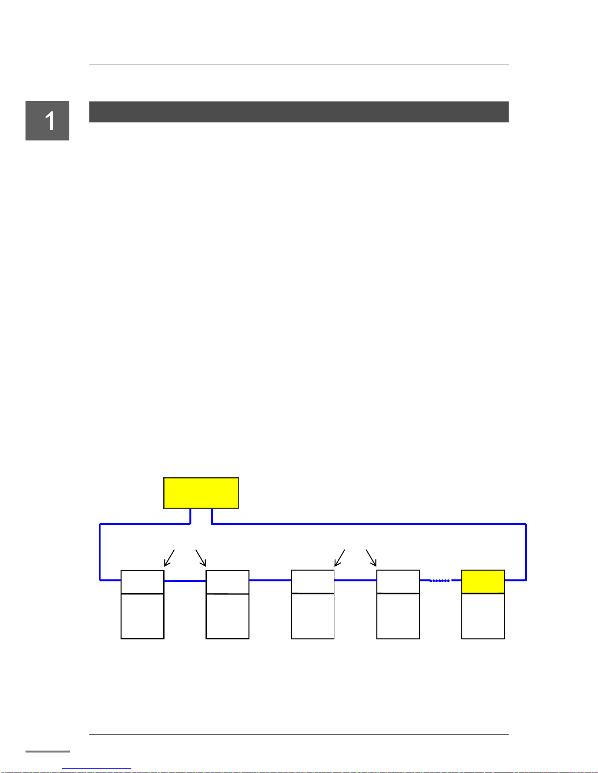
Figure 1-1 Example of using GA932
GA932
GA922-1,GA922-2 : G2 I/O adapter
SA912-1,SA912-2 : TC-net I/O adapter
GA932 : G3 I/O adapter
PUM12
Controller
High speed serial TC
-
net I/O Loop
G2 I/O
adapter
LP1
Node 14
Node: 3
Node 7
Node 8
Node 4
SA912-1
TC-net I/O
Module
G3 I/O
Module
GA922-2
GA922-1
G2-I/O
Module
LP2
G2-I/O
Module
TC-net
I/O adapter
LP2
SA912-2
TC-net I/O
Module
LP2
LP2
LP1
LP1
LP1
LP1
LP2
・When there are up to 16 I / O modules under GA 922,
GA 922 uses the node number for one module.
・When there are 16 or more I / O modules under GA 922,
GA 922 uses the node number for two modules.
1.1 Functions and Characteristics of GA932 Module
Unified Controller nv series G3 I/O Adapter GA932 Module Instruction Manual
3
Note
•
For the supported G3 I/O modules, refer to "Appendix A.3 G3 I/O Module Support List."
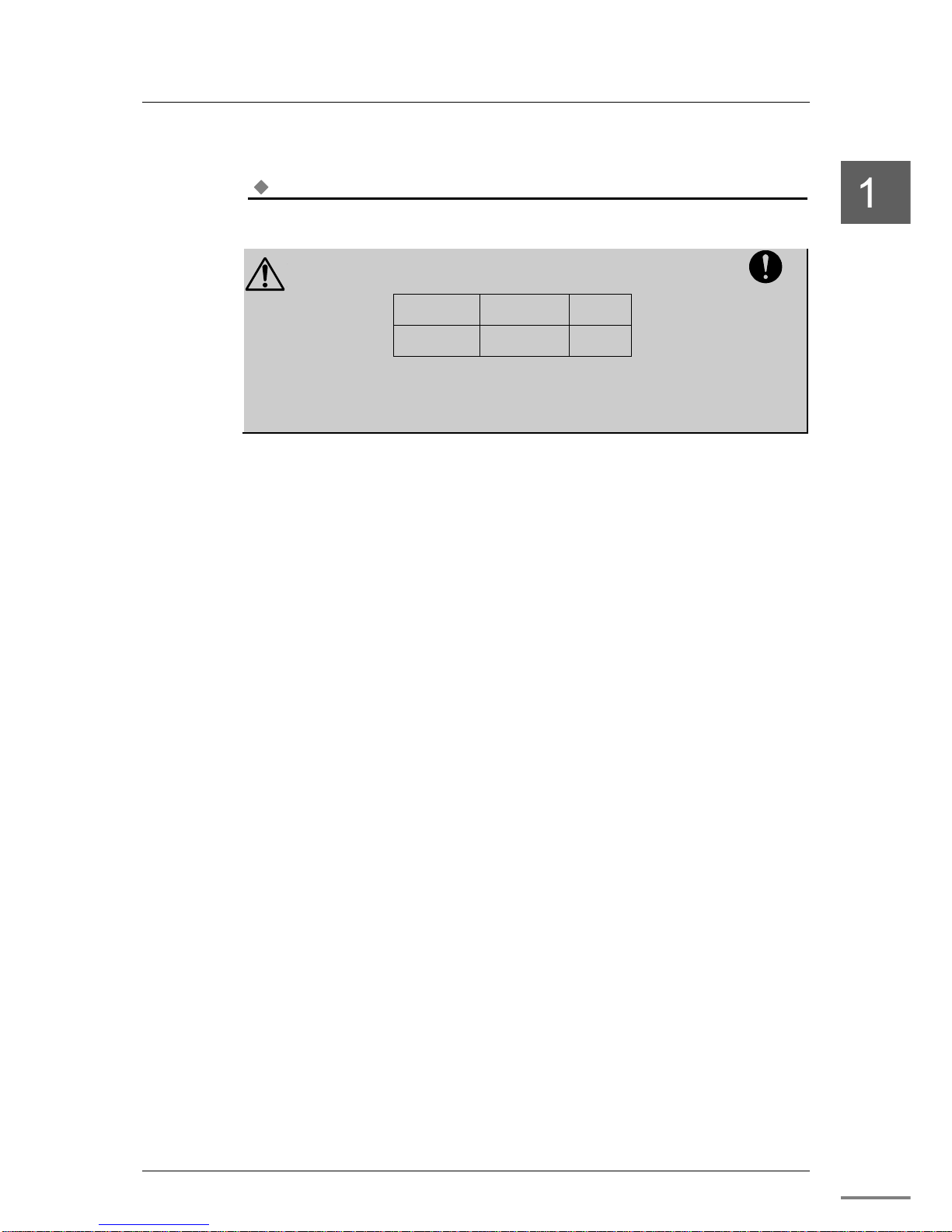
CAUTION
When using G3 I/O module, a combination of
the versions
as follows is required for PUM12 and nV-Tool.
Controller type Controller
modules
nV-
Tool
PUM12 V01.70
or later
V4.13.1
or later
Before using GA932, check the versions of PUM12 and
nV-Tool. For information on how to check the versions,
refer to "Engineering Tool 4 Operation Manual–Basic(6F8C1290)."
Mandatory
Chapter 1 Introducing GA932 Module
6F8C1590
4
1.1.1 System Configuration
■ Example configuration of PUM12 system applying GA932
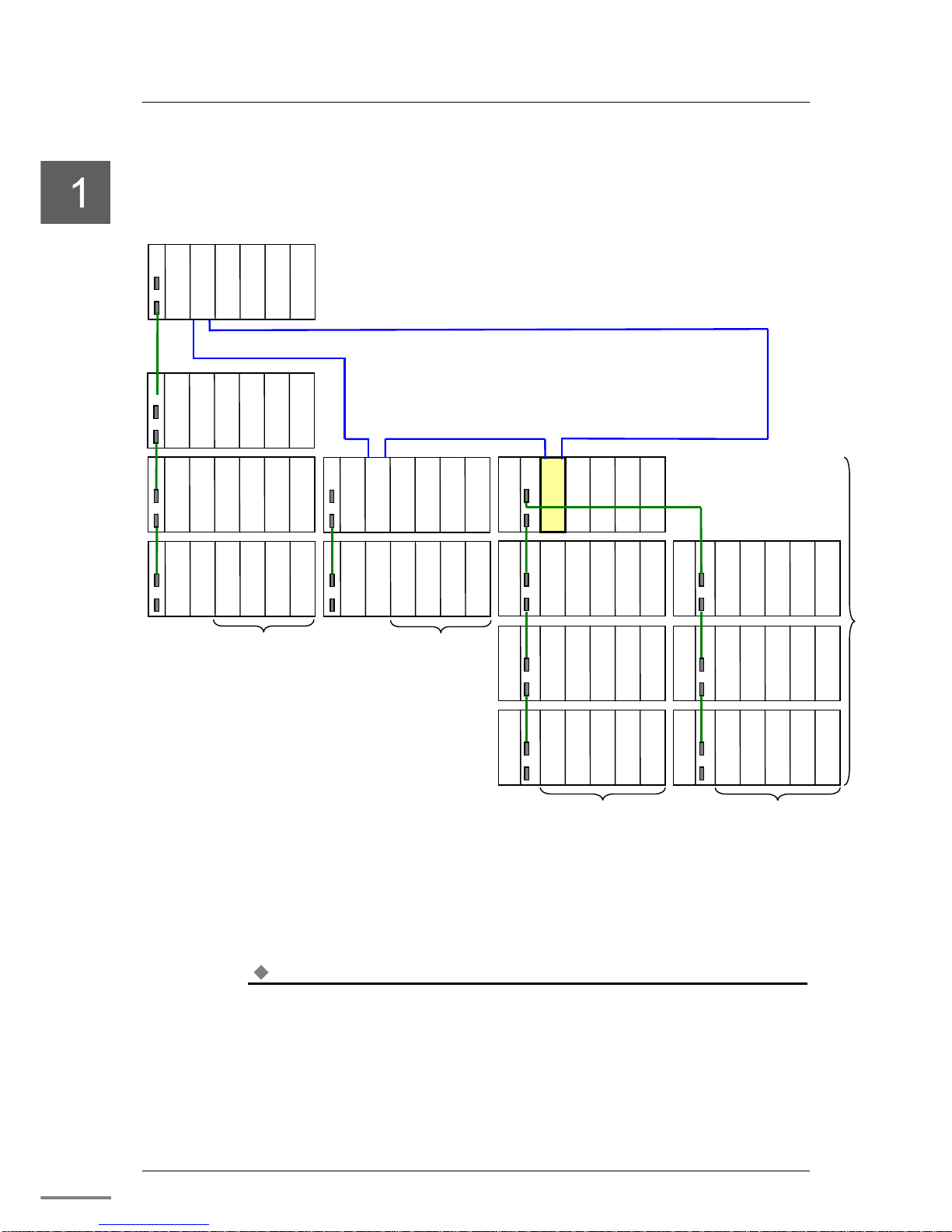
Figure 1-2 Example configuration of PUM12 system applying GA932
Note
•
GA932 or GA922 module can’t be duplicated.
IF
PS
G3 I/O
G3 I/O
G3 I/O
・・
GA932
GA932
Up to 8 modules
Up to 11 modules
(Up to 10 basic modules)
TC-net I/O Optical loop
Maximum 12 Node per PUM12 controller
IF
PS
G2 I/O
G2 I/O
G2 I/O
・・
GA922
IF
PS
G2 I/O
G2 I/O
G2 I/O
・・
IF
PS
G2 I/O
G2 I/O
G2 I/O
・・
IF
PS
G2 I/O
G2 I/O
G2 I/O
・・
IF
PS
G2 I/O
G2 I/O
G2 I/O
・・
IF
PS
G2 I/O
G2 I/O
G2 I/O
・・
PUM12
Number of Node of GA932 : 1 Node
Number of Node of GA922 :1 Node (When 1 or 2 units exist)
2 Node (When 3 or 4 units exist)
Up to 8 modules
IF
PS
G3 I/O
G3 I/O
G3 I/O
・・
G3 I/O
IF
PS
G3 I/O
G3 I/O
G3 I/O
・・
G3 I/O
IF
PS
G3 I/O
G3 I/O
G3 I/O
・・
G3 I/O
IF
PS
G3 I/O
G3 I/O
G3 I/O
・・
G3 I/O
IF
PS
G3 I/O
G3 I/O
G3 I/O
・・
G3 I/O
IF
PS
G3 I/O
G3 I/O
G3 I/O
・・
G3 I/O
Up to 11 modules
Up to 7 units
Vacant
Vacant
Vacant
Vacant
1.1 Functions and Characteristics of GA932 Module
Unified Controller nv series G3 I/O Adapter GA932 Module Instruction Manual
5
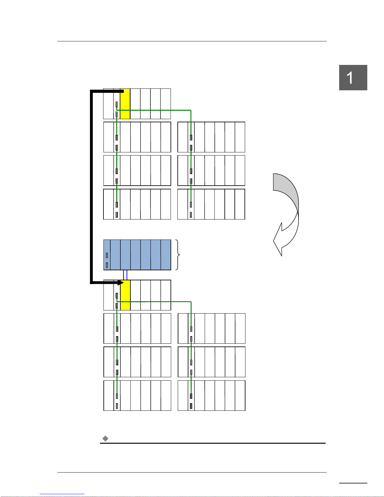
■ Example of updating from T3/T3H system to type 1 light system
Figure 1-3 Example of updating from T3/T3H system to type 1 light system
Note
•
There are restrictions when migrating from T3/T3H. For details, refer to "T series Migration
Hardware Manual “ (6F8C1587)
【
T3/T3H system
】
(3) Connect by TC-net I/O optical loop
IF
PS
G2 I/O
G2 I/O
G2 I/O
・・
PUM12
IF
PS
G3 I/O
G3 I/O
G3 I/O
・・
T3/T3H
IF
PS
G3 I/O
G3 I/O
G3 I/O
・・
G3 I/O
IF
PS
G3 I/O
G3 I/O
G3 I/O
・・
G3 I/O
IF
PS
G3 I/O
G3 I/O
G3 I/O
・・
G3 I/O
IF
PS
G3 I/O
G3 I/O
G3 I/O
・・
G3 I/O
IF
PS
G3 I/O
G3 I/O
G3 I/O
・・
G3 I/O
IF
PS
G3 I/O
G3 I/O
G3 I/O
・・
G3 I/O
IF
PS
G3 I/O
G3 I/O
G3 I/O
・・
GA932
IF
PS
G3 I/O
G3 I/O
G3 I/O
・・
G3 I/O
IF
PS
G3 I/O
G3 I/O
G3 I/O
・・
G3 I/O
IF
PS
G3 I/O
G3 I/O
G3 I/O
・・
G3 I/O
IF
PS
G3 I/O
G3 I/O
G3 I/O
・・
G3 I/O
IF
PS
G3 I/O
G3 I/O
G3 I/O
・・
G3 I/O
IF
PS
G3 I/O
G3 I/O
G3 I/O
・・
G3 I/O
T3/T3H
【
type1 light system
】
(2) Add type1 light controller(PUM12)
(1)
Replace T3/T3H with GA932.
(2)
Add type1 light controller(PUM12)
(Add G2 I/O if necessary)
(3)
Connect
PUM12 and GA932
by TC-net I/O optical loop.
(1) Replace
T3/T3H with
GA932
Chapter 1 Introducing GA932 Module
6F8C1590
6
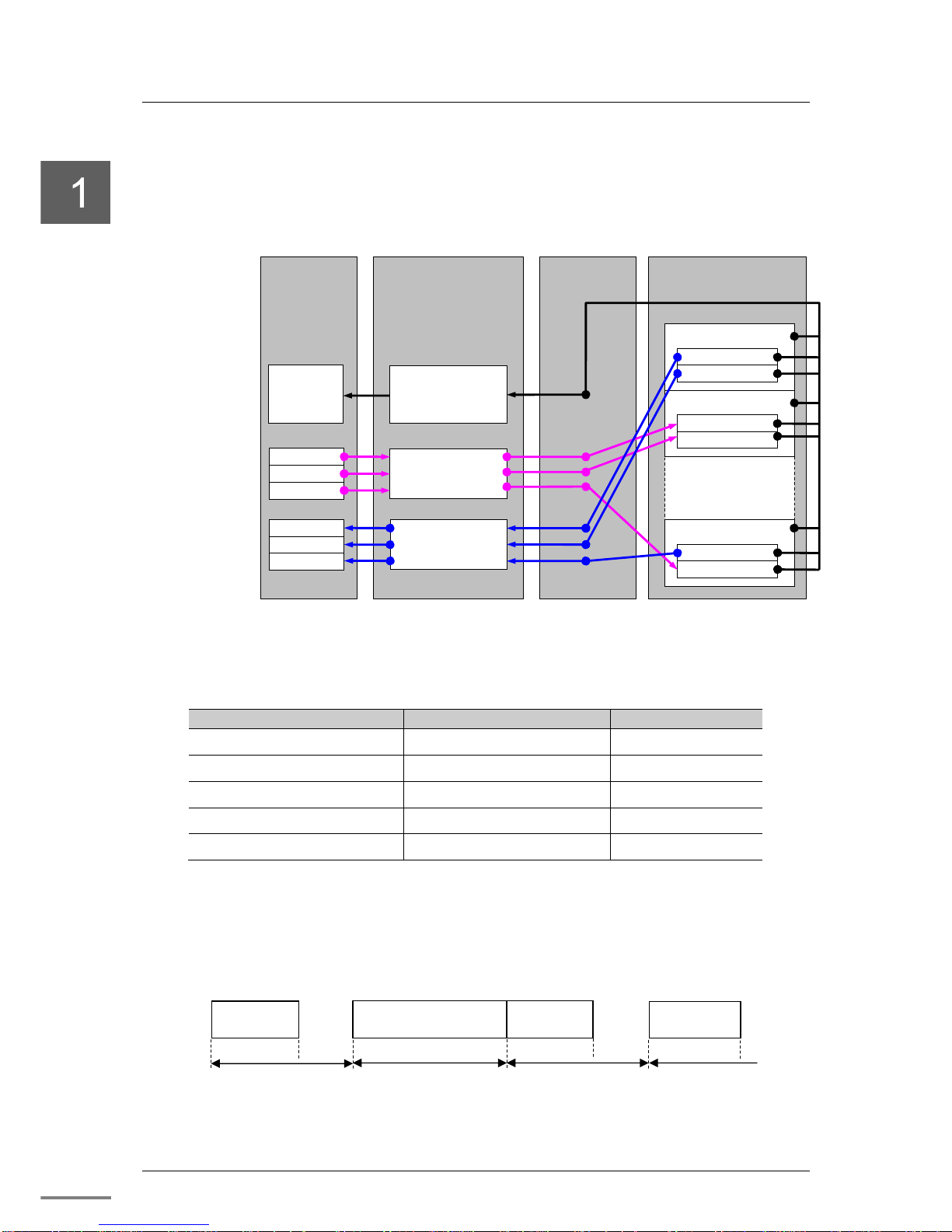
1.1.2 Data input/output with G3 I/O module
By referring the download information by the nv-Tool, GA932 module
transfers G3 I/O input data and G3 I/O output data to TC-net I/O loop scan
memory.
Figure 1-4 G3 I/O data I/O overview
Table 1-1 TC-net I/O loop scan assignment memory map
Use
TC-net I/O loop scan block No
. Number of used blocks
G3 I/O management information (Node No.-3) 1
G3 I/O control information (Node No.-3)×16+96 1
G3 I/O output data (Node No.-3)×16+640 Maximum 16
G3 I/O input data
1152
Maximum 32
Online map (Node No.-3)×16+96+8 2
In addition, G3 I/O input/output operation cycle in GA932 module starts
next I/O after 10ms form the beginning of one input/output.
When the input/output time exceeds 10ms, the next input/output is started
immediately after completion of the input/output.
*1: For input/output time, refer to "Appendix A.2 GA932 Specifications."
Figure 1-5 G3 I/O data input/output operation cycle
G2I/O
:
G2I/O
adapter
GA932
TC-net I/O loop scan
memory
G3 I/O
management
information
G3 I/O output data
G3 I/O input data
U
nit #0
Expansion unit #
1
Expansion unit #
6
Input module
Input
module
Output module
Output module
Input module
Output module
nv -controller
I/O variable 1
I/O variable 2
I/O variable 3
I/O variable 4
I/O variable 5
I/O variable 6
G3 I/O
Diagnosis
processing
*1
10ms
*1
10ms
*1
10ms
*1
G3 I/O
Input /Output
G3 I/O
Input /Output
G3 I/O
Input /Output
G3 I/O
Input /Output

1.1. Functions and Characteristics of GA932 Module
Unified Controller nv series G3 I/O Adapter GA932 Module Instruction Manual
7
Note
•
GA932 imports input data of G3I/O, but does not perform output processing for G3 I/O, while
PUM12 is “HALT”. Therefore, even when PUM12 is “HALT”, the communication module of G3
I/O (Ex. TOSLINE-F10 (MS311)) imports input data captured as G3 I/O, the LED indicating the
reception status may blink.
The reason why G3 I/O transmission module, such as TOSLINE-F10 (MS311), flicks the LED
which indicates the data receiving though the nv controller is halted is described above.
1.1.3 Online map/Online status for G3 I/O module
When G3 I/O transmission module is used, the online map and online status of
the transmission module is entered into the resister of the nv-controller. For the
register configuration, refer to the function manual of each controller.
Table 1-2 Online map/Online status for the transmission module
Controller type
Register type
type1 light Special register (SW register)
Refer to "Appendix A.3 G3 I/O Module Support List" about transmission
module to enter online map and online status.
Chapter 1 Introducing GA932 Module
6F8C1590
8
1.2 Names and Functions of the Parts
1.2.1 Names of the parts
Figure 1-6 shows the names of the parts of GA932 module.
Figure 1-6 Names of the parts of GA932
Note
•
Tool connector “TOOL” is a connector dedicated to maintenance of our company, so please do
not use it. GA932 may stop working.
•
Do not remove the tool connector cap.
State display
LED
Operation mode setting
switch
Maintenance switch
Node No
. setting switch
S
lide lever
Tool connector
(
For maintenance of our
company
)
TC-net I/O loop
Optical connector
Fixing screw
1.2. Names and Functions of the Parts
Unified Controller nv series G3 I/O Adapter GA932 Module Instruction Manual
9
1.2.2 Functions of the parts
The major functions of the parts are as shown below.
■ State display LED
Table 1-3 Details on the state display LED
LED name
Display
Normal display
RUN (green) ON: Module is normal
OFF: Module is abnormal
ON
ERR (red) ON: Module is abnormal
OFF: Module is normal
OFF
I/O(green)
ON: Accessing I/O
OFF: Stop accessing I/O
ON
LP (green) ON: TC-net I/O Loops establishment
OFF: TC-net I/O Loops have loop cutting point
Blinking: Node number duplication
ON
SCAN(green) ON: TC-net I/O Loop scan data transmission is in execution
OFF: TC-net I/O Loop scan data transmission is under suspension
Blinking: Duplication detection of scan talker block
ON
ACT1(green) Blinking: LP1 transmission is performed successfully
Other: Transmission is not performed
Blinking
LINK1(green) ON: LP1 link has been established normally
OFF: No link has been established
ON
ACT2(green) Blinking: LP2 transmission is performed successfully
Other : Transmission is not performed
Blinking
LINK2(green) ON: LP2 link has been established normally
OFF: No link has been established
ON
Note
•
Check the LED state from the front.
•
When the maintenance switch is set to the maintenance state (MAINT), only ERR LED goes on.
Chapter 1 Introducing GA932 Module
6F8C1590
10
■ Operation mode setting switch (MODE)
MODE is the switch for setting the operation mode. Please use this switch all
OFF. For details, refer to "Chapter 3 Setting."
■ Maintenance switch (MAINT)
MAINT is used to restart GA932 module.
For details, refer to "Chapter 3 Setting."
■ Node number setting switch
Node number setting switch is a rotary switch for setting the Node number of
the unit on which GA932 module is installed.
For details, refer to "Chapter 3 Setting."
■ TC-net I/O loop optical connector
This connector is used to connect TC-net I/O optical cable.
Refer to "Appendix A.4 TC-net I/O loop transmission specification" for
applicable optical cable, "Chapter 2 Installation and Wiring” for wiring optical
cables.
■ Tool Connector
This tool connector is for maintenance of our company. Please use with
attached tool connector cap attached.
■ Slide lever
Operate when removing GA932 module from the base unit.
For details, refer to "Chapter 2 Installation and Wiring”
■ Fixing screw
This screw is to fix GA932 module to the base unit.
For details, refer to "Chapter 2 Installation and Wiring”
CAUTION
GA932 is not removable when online. Do not insert or
remove GA932 module while the power is ON. Also,
Please do not connect or disconnect other modules and
cables while the power is ON.
Mandatory
CAUTION
G3 I/O does not do degeneracy recovery. G3 I/O is not
removable when online, GA932 does not perform access
check after disconnectiong abnormal G3 I/O.Turn off the
power of the basic unit and the expansion unit ,and then
restart it after replacing G3 I/O.
Mandatory

11
Chapter 2
Installation and Wiring
This chapter describes how to install and wire GA932 module.
Before installation and wiring, read this operation manual thoroughly.
2.1 Types of I/O Base Units
················································ 13
2.2 Installing / Removing the Module
································· 14
2.3 TC-net I/O Loop Wiring
················································ 17
2.4 Replacing the Module
·················································· 19
2.5 Handling the RUN Signal (RUN contact) of G3 I/O
········ 20
Chapter 2 Installation and Wiring
6F8C1590
12
WARNING
Before installing or removing the module,
make sure that the power of the I/O base
unit to which GA932 module is installed is
turned off.
Otherwise, it may cause an electric shock.
Mandatory
WARNING
Do not touch the interior of the product
except the switches.
It may cause an electric shock.
Prohibited
CAUTION
Install it under an environment that
satisfies the product specifications.
When installing it under an environment that does not
satisfy the product operating temperature range, apply
forced cooling with cooling equipment.
Operating temperature range: 0 to 55°C
Prohibited
CAUTION
Before installation or wiring, remove the
static electricity from your body.
The static electricity accumulated in the human body may
cause failure of the product.
Prohibited
CAUTION
Do not touch the cables carelessly.
Applying stress to the cables may cause malfunction or
accidents.
Prohibited
CAUTION
Do not perform wiring, insertion or
installation of the module, removal or
replacement of the base unit while the
power is on.
It may cause an electric shock.
Prohibited
CAUTION
When installing the product to the I/O base
unit, do not to break or bend the pins of G3
I/O bus connector.
Prohibited
CAUTION
When it is hard to insert the module to the
I/O base unit, remove it and then try to
install it again rather than trying to install it
forcefully.
Prohibited
CAUTION
Use a screwdriver.
To prevent damage to the screws, use a screwdriver that
is suitable for the screws.
Prohibited
 Loading...