

Toshiba G9M-014-10350HW23F, G9M-014-10250HW23F, G9M-014-10125HW63F, G9M-014-10500HW23F, G9M-014-10250HW63F Installation And Operation Manual
...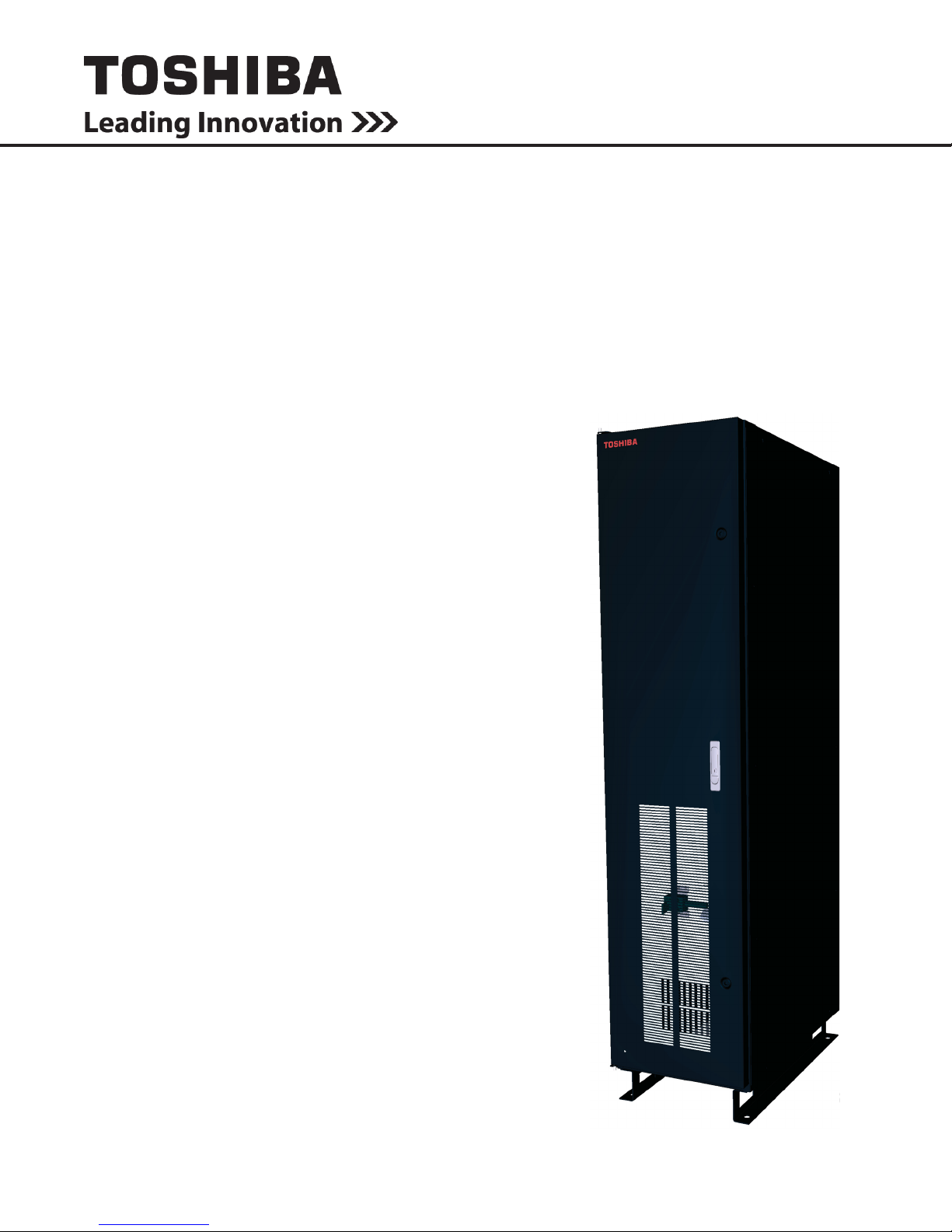
UNINTERRUPTIBLE POWER SYSTEM (UPS)
G9000 SERIES
Slim Maintenance Bypass
INSTALLATION AND OPERATION MANUAL
Part # 96011-000
October 2016
Manufactured in the USA
© Copyright 2016 TOSHIBA International Corporation
All rights reserved.

G9000 Slim MBS Installation and Operation Manual – 96011-000
UNINTERRUPTIBLE POWER SYSTEM (UPS)
G9000 Series
Slim Maintenance Bypass
INSTALLATION AND OPERATION MANUAL
Part # 96011-000
October 2016
G9000 Slim MBS Installation and Operation Manual – 96011-000
Product Use and Warranty Restrictions
The Toshiba products listed in this document are intended for usage in general electronics applications
(computer, personal equipment, ofce equipment, measuring equipment, industrial robotics, domestic
appliances, etc.). These Toshiba products are neither intended nor warranted for usage in equipment that
requires extraordinarily high quality and/or reliability or where a malfunction or failure may cause loss
of human life or bodily injury (Unintended Usage). Unintended Usage includes atomic energy control
instruments, airplane or spaceship instruments, transportation instruments, trafc signal instruments,
combustion control instruments, life-support equipment, all types of safety devices, etc. Unintended Usage
of Toshiba products listed in this document shall be made at the customer’s own risk.
NOTICE
PLEASE INFORM TOSHIBA INTERNATIONAL CORPORATION OR AUTHORIZED
REPRESENTATIVE IN CASE OF INCONSISTENCIES, OMISSIONS, OR QUESTIONS.
The instructions contained in this manual are not intended to cover all of the details or variations in
equipment, or to provide for every possible contingency concerning installation, operation, or maintenance.
Should further information be required or if problems arise which are not covered sufciently, contact your
Toshiba sales ofce.
The contents of this instruction manual shall not become a part of or modify any prior or existing agreement,
commitment, or relationship. The sales contract contains the entire obligation of Toshiba International
Corporation Power Electronics Division. The warranty contained in the contract between the parties is
the sole warranty of Toshiba International Corporation Power Electronics Division and any statements
contained herein DO NOT create new warranties or modify the existing warranty.
Any electrical or mechanical modications to this equipment without prior written consent of Toshiba
International Corporation will void all warranties and may void the UL/CUL listing. Unauthorized modications
can also result in personal injury, loss of life, or destruction of the equipment.
QUALIFIED PERSONNEL ONLY
Qualied Personnel are those who have the skills and knowledge relating to the construction,
installation, operation, and maintenance of the electrical equipment and have received safety
training on the hazards involved (Refer to the latest edition of NFPA 70E for additional safety
requirements).
G9000 Slim MBS Installation and Operation Manual – 96011-000
UNINTERRUPTIBLE POWER SYSTEM (UPS)
Please complete the following information and retain for your records.
Unless otherwise specied, the warranty period for the UPS or UPS part is 36 months from the shipment
date (see Toshiba International Corporation bill of lading).
Unless otherwise specied, the warranty period for a UPS battery is 24 months from the shipment date (see
Toshiba International Corporation bill of lading).
Unless otherwise specied, the warranty period for the MBS is 36 months from the shipment date (see
Toshiba International Corporation bill of lading).
JOB NUMBER
MODEL NUMBER
SERIAL NUMBER
APPLICATION
SHIPMENT DATE
INSTALLATION DATE
INSPECTED BY
G9000 Slim MBS Installation and Operation Manual – 96011-000

Purpose
This manual provides information on how to safely install your Toshiba International Corporation power
electronics product. This manual includes a section of general safety instructions that describes the warning
labels and symbols that are used throughout the manual. Read the manual completely before installing,
operating, or performing maintenance on this equipment.
This manual and the accompanying drawings should be considered a permanent part of the equipment and
should be readily available for reference and review. Dimensions shown in the manual are in metric and/or
the English customary equivalent.
Toshiba International Corporation reserves the right, without prior notice, to update information, make
product changes, or discontinue any product or service identied in this publication.
Toshiba is a registered trademark of the Toshiba Corporation. All other product or trade references appearing
in this manual are registered trademarks of their respective owners.
Toshiba International Corporation shall not be liable for direct, indirect, special, or consequential
damages resulting from the use of the information contained within this manual.
This manual is copyrighted. No part of this manual may be photocopied or reproduced in any form without
the prior written consent of Toshiba International Corporation.
© Copyright 2016 Toshiba International Corporation
All rights reserved.
Printed in the U.S.A.
Toshiba Customer Support Center
Contact the Toshiba Customer Support Center for assistance with application information or for any
problems that you may experience with your Uninterruptible Power System Auxiliary Cabinet.
Toshiba Customer Support Center
8 a.m. to 5 p.m. (CST) - Monday through Friday
USA Toll Free
Pre-Sales Application Support: (855) 803-7087
Tech/Service Support: (877) 867-8773
Tel: (713) 466-0277
Fax: (713) 466-8773
E-mail – TIC-UPS-RST-CSR@toshiba.com
Web – https://www.toshiba.com/tic/industrial/uninterruptible-power-systems
You may also contact Toshiba by writing to:
TOSHIBA INTERNATIONAL CORPORATION
INFRASTRUCTURE SYSTEMS & SOLUTIONS COMPANY
POWER ELECTRONICS DIVISION
13131 West Little York Road
Houston, Texas 77041-9990
Attn: UPS Product Manager
For further information on Toshiba products and services, please visit our website at:
www.toshiba.com/tic/industrial/uninterruptible-power-systems
G9000 Slim MBS Installation and Operation Manual – 96011-000

Contents
1 Introduction ................................................................................................1
1.1 System Compatibility .........................................................................1
2 General Safety Instructions ......................................................................2
2.1 Symbols .........................................................................................2
2.2 Signal Words .................................................................................3
2.3 Qualied Personnel .......................................................................3
2.4 Factory Authorized Personnel........................................................4
3 Important Safety Instructions ...................................................................4
3.1 Maximum Operating Temperatures ...............................................4
4 Safety Precautions ....................................................................................5
4.1 Disclaimer ......................................................................................5
4.2 General Maintenance ....................................................................5
4.3 Transporting ...................................................................................6
5 Storage/Operating Environment ..............................................................7
5.1 Inspection/Storage .........................................................................7
5.2 Storage Environment ....................................................................7
5.3 Operating Precautions ....................................................................8
5.4 Maintenance Precautions ...............................................................9
6 Unpacking ..................................................................................................10
6.1 General Instructions.......................................................................10
6.2 Unpack the Slim Maintenance Bypass Cabinet .............................10
6.3 Transporting By Forklift ..................................................................11
7 Installation..................................................................................................12
7.1 Installation Precautions..................................................................12
7.2 Slim MBS Cabinet Clearance ........................................................13
8 MBS Component Layout ...........................................................................15
9 MBS Operation ...........................................................................................16
10 MBS One-line Drawing ..............................................................................17
G9000 Slim MBS Installation and Operation Manual – 96011-000
i

This Page Left Blank Intentionally
ii
G9000 Slim MBS Installation and Operation Manual – 96011-000

1 Introduction
This manual provides information on how to safely install and operate your G9000 Series Maintenance
Bypass Cabinet. This manual includes a section of general safety instructions that describes the warning
labels and symbols that are used throughout the manual. Read the manual completely before installing,
operating, or performing maintenance on this equipment.
Qualied personnel should read this manual carefully before transporting, installing, and wiring the UPS
Ancillary Cabinets. In addition they have a thorough understanding of the information provided in the
chapters titled:
• General Safety Instructions
• Important Safety Instructions
• Safety Precautions
• Installation Precautions
Please read the G9000 Series UPS Installation and Operation Manual in addition to this manual for important
instructions on installing and operating the Maintenancy Bypass Cabinet in accompaniment with the UPS.
This manual and the accompanying drawings should be considered a permanent part of the equipment and
should be readily available for reference and review. Dimensions shown in the manual are in metric and/or
the English customary equivalent.
Keep the Installation Manual and the Operation Manual near the Maintenance Bypass for necessary
reference.
1.1 System Compatibility
This manual is designed to be used as a reference with products with the following Toshiba part numbers:
G9M-014-10125HW23F
G9M-014-10150HW23F
G9M-014-10250HW23F
G9M-014-10350HW23F
G9M-014-10500HW23F
G9M-014-10125HW63F
G9M-014-10150HW63F
G9M-014-10250HW63F
G9M-014-10350HW63F
G9M-014-10500HW63F
SAVE THESE INSTRUCTIONS
G9000 Slim MBS Installation and Operation Manual – 96011-000
1

2 General Safety Instructions
DO NOT attempt to transport, install, operate, maintain or dispose of this equipment until you have read and
understood all of the product safety information provided in this manual.
2.1 Symbols
The symbols listed below are used throughout this manual. When symbols are used in this manual they will
include important safety information that must be carefully followed.
Safety Alert Symbol indicates that a potential
personal injury hazard exists.
Prohibited Symbol indicates DO NOT take action.
Mandatory Symbol indicates that the following
instruction is required.
Ground Symbol indicates the location of the
equipment grounding conductor.
Electrical - Voltage & Shock Hazard Symbol
indicates parts inside may cause electric shock.
Explosion Hazard Symbol indicates parts may
explode.
2
G9000 Slim MBS Installation and Operation Manual – 96011-000

2.2 Signal Words
The signal words listed below are used throughout this manual. When the words DANGER, WARNING,
CAUTION and ATTENTION are used in this manual they will include important safety information that
must be carefully followed.
The word DANGER in capital letters preceded by
DANGER
WARNING
CAUTION
the safety alert symbol indicates that an imminently
hazardous situation exists, and if not avoided
will result in loss of life or serious injury to
personnel.
The word WARNING in capital letters preceded by
the safety alert symbol indicates that a potentially
hazardous situation exists, and if not avoided
may result in loss of life or serious injury to
personnel.
The word CAUTION in capital letters preceded by
the safety alert symbol indicates that a potentially
hazardous situation exists, and if not avoided may
result in minor or moderate injury.
The word NOTICE in capital letters without
NOTICE
the safety alert symbol indicates a potentially
hazardous situation exists, and if not avoided may
result in equipment and property damage.
2.3 Qualied Personnel
Installation, operation, and maintenance shall be performed by Qualied Personnel Only. A Qualied
Person is one who has the skills and knowledge relating to the construction, installation, operation, and
maintenance of the electrical equipment and has received safety training on the hazards involved (Refer
to the latest edition of NFPA 70E for additional safety requirements).
Qualied Personnel shall:
• Have read the entire operation manual.
• Be familiar with the construction and function of the Maintenance Bypass Cabinet, the equipment
being driven, and the hazards involved.
• Be trained and authorized to safely energize, de-energize, ground, lockout/tagout circuits and
equipment, and clear faults in accordance with established safety practices.
• Be trained in the proper care and use of protective equipment such as safety shoes, rubber gloves,
hard hats, safety glasses, face shields, ash clothing, etc., in accordance with established safety
practices.
• Be trained in rendering rst aid.
For further information on workplace safety visit www.osha.gov.
G9000 Slim MBS Installation and Operation Manual – 96011-000
3

2.4 Factory Authorized Personnel
Factory authorized personnel have been factory trained and certied to install, service, and repair the
UPS. Contact the Toshiba Customer Support Center for assistance in locating the factory authorized
personnel nearest you.
3 Important Safety Instructions
The following contains important instructions that should be followed during the installation, operation, and
maintenance of the G9000 Series Maintenance Bypass Cabinet.
3.1 Maximum Operating Temperatures
CAUTION
Misuse of this equipment could result in personal injury and/or equipment damage.
In no event will Toshiba Corporation be responsible or liable for either indirect or
consequential damage or injury that may come from the use of this equipment.
The maximum operating ambient temperature for the G9000 Series Maintenance Bypass Cabinet is:
• G9M (Slim MBS Cabinet) – 104 °F (40 °C).
4
G9000 Slim MBS Installation and Operation Manual – 96011-000

4 Safety Precautions
The Toshiba products listed in this document are intended for usage in general electronics applications
(computer, personal equipment, ofce equipment, measuring equipment, industrial robotics, domestic
appliances, etc.). These Toshiba products are neither intended nor warranted for use in equipment that, if
a malfunction or failure occurs, may result in loss of human life or bodily injury (collectively referred to as
“Unintended Usage”). Unintended Usage includes atomic energy control instruments, airplane or spaceship
instruments, transportation instruments, trafc signal instruments, combustion control instruments, life
support equipment, all types of safety devices, etc. Unintended Usage of Toshiba products listed in this
document shall be made at the customer’s own risk.
The application of the UPS without special consideration for equipment that supports human safety and/or
maintain public services may cause serious accidents.
4.1 Disclaimer
IN NO EVENT WILL TOSHIBA CORPORATION BE RESPONSIBLE OR LIABLE FOR EITHER INDIRECT
OR CONSEQUENTIAL DAMAGE OR INJURY THAT MAY COME FROM THE MISUSE OF THIS
EQUIPMENT. ANY MODIFICATIONS WITHOUT AUTHORIZATION BY TOSHIBA COULD RESULT IN
PERSONAL INJURIES, DEATH OR DESTRUCTION OF THE AUXILIARY CABINET.
TOSHIBA RESERVES THE RIGHT TO MAKE CHANGES WITHOUT FURTHER NOTICE TO ANY
PRODUCTS HEREIN TO IMPROVE RELIABILITY, FUNCTION OR DESIGN. TOSHIBA DOES NOT
ASSUME ANY LIABILITY ARISING OUT OF THE APPLICATION OR USE OF ANY PRODUCT OR
AUXILIARY CABINET DESCRIBED HEREIN; NEITHER DOES IT CONVEY ANY LICENSE UNDER ITS
PATENT RIGHTS, NOR THE RIGHTS OF OTHERS.
4.2 General Maintenance
DO NOT remove the rear/side panels, or any sheet metal not designed to be
removed.
Removing rear/side panels may result in electric shock, burns, personal injuries or
Maintenance Bypass Cabinet failure.
Keep the area around the Maintenance Bypass Cabinet clean.
Use a non-metal vacuum cleaner to clean the Auxiliary Cabinet.
Only factory authorized personnel should perform internal general maintenance
on the UPS and Maintenance Bypass Cabinet.
Contact the authorized Toshiba Customer Support Center or an authorized
Toshiba representative for information on proper disposal of UPS and
Maintenance Bypass Cabinet components.
It is illegal to dispose of certain components without conforming to environmental
regulations for industrial/commercial waste.
WARNING
G9000 Slim MBS Installation and Operation Manual – 96011-000
5

4.3 Transporting
WARNING
DO NOT tilt the Maintenance Bypass Cabinet more than 10° from
upright position.
Tilting more than 10° may cause crushing, trapping or other personal
injuries.
CAUTION
DO NOT transport, move, store, or place the Maintenance Bypass
Cabinet on its sides.
Excessive force applied from heavy components inside may damage
the Maintenance Bypass Cabinet.
Avoid vibration or shock exceeding 0.5 g.
Failing to observe this precaution may cause damage to the
Maintenance Bypass Cabinet.
DO NOT allow the Maintenance Bypass Cabinet to suffer shock
or impact when unpacking.
Tools used to remove packaging materials may cause damage to the
Maintenance Bypass Cabinet
DO NOT install the Maintenance Bypass Cabinet where water
may fall on it.
Water may cause electrical shock, personal injury or Maintenance
Bypass Cabinet failure.
DO NOT push or pull on the sides of the packaging or the
Maintenance Bypass Cabinet to move it. Always use a crane,
forklift, or pallet jack for transporting and positioning the
cabinet.
Pushing/pulling on the sides of the unit to move it may result in damage
to the Maintenance Bypass Cabinet.
The Maintenance Bypass Cabinet may be packed in a crate for extra protection during transportation.
Avoid impact or vibration against the Maintenance Bypass Cabinet during transportation. DO NOT expose
the Maintenance Bypass Cabinet directly to water.
6
G9000 Slim MBS Installation and Operation Manual – 96011-000

5 Storage/Operating Environment
5.1 Inspection/Storage
Inspection
Upon receipt of the Slim MBS, an inspection for shipping damage should be performed. Use caution when
removing the unit from the pallet. Refer to labels or documentation attached to packing material.
Unpacking
Check the unit for loose, broken, bent or otherwise damaged parts. If damage has occurred during shipping,
keep all original crating and packing materials for return to the shipping agent.
NOTE: The factory warranty does not apply to damage incurred during shipping!
Ensure that the rated capacity and the model number specied on the nameplate conform to the order
specications.
Storage
During periods of non-use, the following guidelines are recommended for storage.
Storage Preparation
• Place all MBS Circuit Breaker switches in the “OFF” position.
Storage Conditions
• For best results, store the Slim MBS cabinet in the original shipping container and
place on a wood or metal pallet
• Storage temperature range: 32 to 104 °F (0 to 40 °C)
• Avoid the following storage locations:
• Locations that are subject to extreme temperature changes or high humidity
• Locations that are subject to high levels of dust or metal particles
• Locations that are subject to excessive vibration
• Inclined oor surfaces
5.2 Storage Environment
Observe the following when storing the Slim MBS.
• Store indoors.
• Temperature uctuations should be minimized.
• A maximum temperature range of 32 – 104 °F (0 – 40 °C) should be observed.
• The optimal relative humidity at the storage location should be between 50 – 60% without
condensation.
• Humidity must not exceed 90%.
• Avoid locations where the Slim MBS cabinet may be exposed to corrosive gas.
• Avoid locations with dirt and/or dust.
• Avoid locations that are subject to excessive vibration.Avoid inclined oor surfaces.
G9000 Slim MBS Installation and Operation Manual – 96011-000
7

TABLE 5.1 - SLIM MBS CABINET STORAGE/OPERATING ENVIRONMENT
STANDARDS
Item Environment standard
Storage Location Indoors
Ambient Temperature
Relative Humidity
Altitude
Dust
Minimum storage temperature: 32 °F (0 °C)
Maximum storage temperature: 104 °F (40 °C)
The relative humidity must be between 30% and 90% and without
condensation due to temperature changes.
This equipment is rated for installations up to 3240 ft. (1000 m)
above sea level. Consult with the factory to determine the derating
factor for installations above 3240 ft. (1000 m).
Dust must not exceed normal atmospheric levels and must not
include conductive/corrosive particles, silicone or oils.
No ammable and/or explosive gas.
Hydrogen sulde (H2S) Less than or equal to 0.0001 PPM
Sulfurous acid gas (SO2) Less than or equal to 0.05 PPM
Chlorine gas (Cl2) Less than or equal to 0.002 PPM
Flammable Gas
Ammonia gas (NH3) Less than or equal to 0.1 PPM
Nitrous acid gas (NO2) Less than or equal to 0.02 PPM
Nitrous oxides (NOx) Less than or equal to 0.02 PPM
Ozone (O3) Less than or equal to 0.002 PPM
Hydrochloric acid mist (HCl) Less than or equal to 0.1 mg/m
3
5.3 Operating Precautions
Initial startup/commissioning of the Slim MBS cabinet should be performed by factory authorized personnel.
1) The Slim MBS cabinet should not be powered up until the entire operation manual has been read. Follow
Lockout/Tag Out procedures.
2) The voltage of the input power source must be within the rated input voltage range. The input frequency
range must be within the rated input frequency range.
3) The Slim MBS cabinet should not be used with a load that has a rated input that is greater than the rated
output of the Slim MBS.
4) DO NOT insert metal objects or combustible materials in the ventilation slots of the Slim MBS cabinet.
5) DO NOT place, hang, or paste any objects on the exterior surfaces of the Slim MBS cabinet.
6) DO NOT attempt to disassemble, modify, or repair the Slim MBS cabinet. Call your Toshiba sales
representative for repair information.
7) Turn the power on only after installing ALL of the covers.
8) DO NOT remove any covers of the Slim MBS cabinet when power is on.
9) If the Slim MBS cabinet should emit smoke or an unusual odor or sound, turn the power off immediately.
10) Additional warnings and notications shall be posted at the equipment installation location as deemed
required by Qualied Personnel.
8
G9000 Slim MBS Installation and Operation Manual – 96011-000

5.4 Maintenance Precautions
All internal maintenance should be performed by factory authorized personnel.
1) Turn off, lockout, and tagout ALL power sources before connecting the power wiring to the equipment or
when performing maintenance.
2) Hard-wire type UPS units are not equipped with an over-current protection device, nor do they have an
output disconnect for the AC output. A user-installed circuit breaker should be provided between the
UPS output and the load input.
3) The maximum ambient operating temperature is 104 °F (40 °C) for the G9000 Slim MBS.
4) Only factory authorized personnel should service the UPS. Contact Toshiba for the nearest authorized
service center.
5) Battery servicing should be performed by factory authorized personnel only.
Note: Contact your nearest factory authorized service center for battery replacement.
Qualied Personnel ONLY!
Qualied Personnel have the skills and knowledge relating to the construction, installation, operation, and maintenance of
the electrical equipment and has received safety training on the hazards involved (Refer to the latest edition of NFPA 70E
for additional safety requirements).
Qualied Personnel shall:
1) Have read the entire operation manual.
2) Be trained and authorized to safely energize, de-energize, ground, lockout and tag circuits and equipment,
and clear faults in accordance with established safety practices.
3) Be trained in the proper use and care of protective equipment such as safety shoes, rubber gloves, hard
hats, safety glasses, face shields, ash clothing, etc., in accordance with established safety practices.
4) Be trained in rendering rst aid.
5) Be knowledgeable of the DC backup supply system and the required handling and maintenance
precautions.
For further information on workplace safety visit www.osha.gov.
Misuse of equipment could result in injury and equipment damage.
In no event will Toshiba Corporation be responsible or liable for either
indirect or consequential damage or injury that may result from the
misuse of this equipment.
G9000 Slim MBS Installation and Operation Manual – 96011-000
WARNING
9

6 Unpacking
6.1 General Instructions
Unpack the Slim MBS Cabinet indoors on a paved oor. The Slim MBS Cabinet should be as close as
possible to its nal location. Allow enough space for forklift operations to unpack the Slim MBS Cabinet from
the packing crate. Then remove the crate. Properly dispose of the crate.
Points to observe:
• Retain all small articles during unpacking and installation.
• Make sure that exterior paint is not scratched and that the Slim MBS Cabinet is not damaged
before uncrating.
• DO NOT damage the Slim MBS Cabinet when using tools to remove packaging materials.
• If provided, DO NOT remove the protective plastic sheet cover until installation.
• Packing materials should be disposed by the appropriate means.
• Immediately report any abnormalities to Toshiba Customer Support Center or an authorized
representative.
• Retain the packing rails, if included, for ofoading the Slim MBS Cabinet from the shipping
pallet.
6.2 Unpack the Slim Maintenance Bypass Cabinet
CAUTION
TOP HEAVY EQUIPMENT. THIS EQUIPMENT WILL TIP OVER EASILY
UNTIL FIXED IN PLACE.
Lift and move carefully, and only with adequate equipment and trained
personnel. IMPROPER LIFTING CAN RESULT IN INJURY OR DEATH.
10
G9000 Slim MBS Installation and Operation Manual – 96011-000

6.3 Transporting By Forklift
Verify forklift maximum load capacity and ensure that the forks are long enough to properly support the
UPS. Insert the forks into the space shown in Figure 6.1. Spaces for the forks are provided underneath
the maintenance bypass cabinet.
DO NOT tilt MBS when lifting and/or transporting. Minimize the impact when lowering the cabinet to the
oor.
Insert the forks here
G9000 Slim MBS Installation and Operation Manual – 96011-000
4 in.
20 in.
4 in.
G9000 Slim MBS Cabinet Cabinet: Side
View - Fork Access Dimensions in Channel
Base
Figure 6.1 - Transporting by Forklift
11

7 Installation
7.1 Installation Precautions
Install the Slim MBS Cabinet in a controlled environment.
Improper storage and installation environment may deteriorate insulation,
shorten component life and cause malfunctions.
See Table 5.1 - Slim MBS Cabinet Installation Environment Standards
DO NOT tilt the Slim MBS cabinet more than 10° from upright position.
Tilting the Slim MBS Cabinet more than 10° may cause crushing, trapping or
other personal injuries and cause physical damage to internal components.
Keep the SPECIFIED CLEARANCE around the UPS.
Inadequate space around the UPS makes it difcult to perform maintenance/
inspections, will lead to insufcient ventilation, and/or cause malfunctions.
CAUTION
WARNING
Only factory authorized personnel should relocate, modify, or
replace parts in the Slim MBS Cabinet after initial installation.
Electrical shock, injury or Slim MBS Cabinet failure may occur if nonauthorized technicians attempt to modify or relocate the Slim MBS
Cabinet.
Please contact Toshiba Customer Support Center if you plan to move or
make modications to the Slim MBS Cabinet
METAL CONDUIT IS NOT AN ACCEPTABLE GROUND.
Conductor Routing and Grounding
1) Use separate metal conduits for routing the input power, output power, and control
circuits.
2) Follow the wire size and tightening torque specications.
3) Always ground the unit to reduce the potential for electrical shock and to help reduce
electrical noise.
4) A separate ground cable should be run inside the conduit with the input power, output
power, and control circuits.
WARNING
12
G9000 Slim MBS Installation and Operation Manual – 96011-000

7.2 Slim MBS Cabinet Clearance
Maintain the indicated clearance during installation. See Figure 7.1. Ensure that the front and top air vents
are NOT blocked.
Top 16 in
(406 mm)
Front
36 in
(914 mm)
Side Clearance:
0 in (0 mm)
FIGURE 7.1 CLEARANCE FOR SLIM MBS CABINET
7.3 Wiring Between UPS & MBS
L1
L2
L3
N
Utility Power
N
L1
L2
L3
Critical Load
MBS
A
B
IN
C
UTILITY
A
B
C
LOAD IN
NEUTRAL
N N N N
TB1
1 2 3 4 5 6 7 8
A
B
C
A
B
C
UPS OUT UPS IN
Rear Clearance:
J1
CNEPO-2
P1
0 in (0 mm)
G9000 Series
UPS
H1
H2
H3
N
TB1
N
L1
L2
L3
(UPS OUT) (UPS IN)
+
-
24V DC PCB
CNEPO-1
FIGURE 7.2 - POWER CABLING BETWEEN SLIM MBS AND UPS
G9000 Slim MBS Installation and Operation Manual – 96011-000
13

8 MBS Component Layout
1
2
3
4
FIGURE 8.1 – FRONT AND INNER COMPONENT LAYOUTS
6
5
7
8
Part Number Part Description
1 Control Transformer
2 UPS Connection
3 Utility Connection
4 Load Connection
14
G9000 Slim MBS Installation and Operation Manual – 96011-000
Part Number Part Description
5 TB-1
6 UIB
7 MBB
8 MIB

9 MBS Operation
Begin this procedure only with the system in the normal operating mode (UPS On-Line)
1. Touch the “Start/Stop” button on the MAIN screen on the UPS Cabinet. Touch and Hold the “Stop”
button until it beeps (this will transfer the UPS to static bypass.) If SKRU in MBS is equipped with a light,
it should now be illuminated, and the key can be removed.
2. Extract the key from the SKRU.
3. Insert the key in the lock on MBB, and unlock MBB.
4. Close MBB (Maintenance Bypass Breaker)
5. Open MIB (UPS Output Isolation Breaker)
6. Lock MIB. Remove the key from the lock on MIB, and insert it in the SKRU.
7. Turn off all DC breakers.
8. At this time, UIB (UPS Input Breaker) may now be opened. Any input isolation breakers to the
rectier input of the UPS must now be opened to isolate the UPS completely.
9. End of Procedure.
System is now on External Maintenance Bypass
This procedure is for the system in the maintenance bypass-operating mode (System is on External
Maintenance Bypass)
1. Close UIB (UPS Input Breaker) and close input isolation breakers to the UPS.
2. Wait until the UPS turns ON.
3. Turn ON all DC breakers.
4. Verify that the UPS is in Bypass via the mimic panel.
5. Verify that the Bypass and Inverter LED’s are on. If so, the key in the SKRU can now be removed.
6. Extract the key from the SKRU. Insert it in the lock on MIB, and unlock MIB.
7. Close MIB (UPS Output Isolation Breaker)
8. Open MBB (Maintenance Bypass Breaker)
9. Lock MBB. Remove key from MBB, and insert it in SKRU.
10. Touch the “Start/Stop” button on the MAIN screen. Touch and hold the “Start” button until it beeps
(this will transfer the UPS to inverter operation.)
11. End of Procedure.
System is now being supported by the UPS.
G9000 Slim MBS Installation and Operation Manual – 96011-000
15

16
G9000 Slim MBS Installation and Operation Manual – 96011-000
10 MBS One-line Drawing

INFRASTRUCTURE SYSTEMS & SOLUTIONS COMPANY
POWER ELECTRONICS DIVISION
13131 West Little York Road, Houston, Texas 77041
Tel (713) 466-0277 Fax. (713) 466-8773
US (800) 231-1412 Canada (800) 872-2192 Mexico 01-800-527-1204
www.toshiba.com/tic/industrial/uninterruptible-power-systems
Printed in the U.S.A.
 Loading...