

Page 1

User’s Manual
Qosmio G40
Page 2

Table of Contents
Copyright. . . . . . . . . . . . . . . . . . . . . . . . . . . . . . . . . . . . . . . . . . . . . . . . . vii
Disclaimer . . . . . . . . . . . . . . . . . . . . . . . . . . . . . . . . . . . . . . . . . . . . . . . . vii
Trademarks. . . . . . . . . . . . . . . . . . . . . . . . . . . . . . . . . . . . . . . . . . . . . . viii
Macrovision License . . . . . . . . . . . . . . . . . . . . . . . . . . . . . . . . . . . . . . viii
FCC information . . . . . . . . . . . . . . . . . . . . . . . . . . . . . . . . . . . . . . . . . . . ix
EU Declaration of Conformity . . . . . . . . . . . . . . . . . . . . . . . . . . . . . . . . . x
VCCI Class B Information . . . . . . . . . . . . . . . . . . . . . . . . . . . . . . . . . . . . x
Important Safety Information for Computers with TV tuner . . . . . . . . . x
Modem warning notice. . . . . . . . . . . . . . . . . . . . . . . . . . . . . . . . . . . . . . xi
Japan regulations. . . . . . . . . . . . . . . . . . . . . . . . . . . . . . . . . . . . . . . . . . xii
Instructions for IC CS-03 certified equipment. . . . . . . . . . . . . . . . . . xiv
Notes for Users in Australia and New Zealand . . . . . . . . . . . . . . . . . . xv
Optical disc drive safety instructions. . . . . . . . . . . . . . . . . . . . . . . . . xix
International precautions. . . . . . . . . . . . . . . . . . . . . . . . . . . . . . . . . . . xxi
Preface
Conventions . . . . . . . . . . . . . . . . . . . . . . . . . . . . . . . . . . . . . . . . . . . . xxiii
General Precautions
Creating a computer-friendly environment . . . . . . . . . . . . . . . . . . . xxvi
Stress injury . . . . . . . . . . . . . . . . . . . . . . . . . . . . . . . . . . . . . . . . . . . . xxvi
Heat injury. . . . . . . . . . . . . . . . . . . . . . . . . . . . . . . . . . . . . . . . . . . . . . xxvii
Pressure or impact damage. . . . . . . . . . . . . . . . . . . . . . . . . . . . . . . . xxvii
PC Card overheating . . . . . . . . . . . . . . . . . . . . . . . . . . . . . . . . . . . . . xxvii
Mobile phones . . . . . . . . . . . . . . . . . . . . . . . . . . . . . . . . . . . . . . . . . . xxvii
Instruction Manual for Safety and Comfort . . . . . . . . . . . . . . . . . . . xxvii
The cautions on use of a Qosmio G40 series computer . . . . . . . xxviii
Chapter 1 Introduction
Equipment checklist. . . . . . . . . . . . . . . . . . . . . . . . . . . . . . . . . . . . . . . 1-1
Hardware . . . . . . . . . . . . . . . . . . . . . . . . . . . . . . . . . . . . . . . . . . . . . . . . 1-3
Special features . . . . . . . . . . . . . . . . . . . . . . . . . . . . . . . . . . . . . . . . . 1-12
TOSHIBA Value Added Package. . . . . . . . . . . . . . . . . . . . . . . . . . . . 1-14
Utilities and Applications. . . . . . . . . . . . . . . . . . . . . . . . . . . . . . . . . . 1-15
User’s Manual ii
Page 3

Options . . . . . . . . . . . . . . . . . . . . . . . . . . . . . . . . . . . . . . . . . . . . . . . . 1-17
Chapter 2 The Grand Tour
Front with the display closed . . . . . . . . . . . . . . . . . . . . . . . . . . . . . . . 2-1
Left side. . . . . . . . . . . . . . . . . . . . . . . . . . . . . . . . . . . . . . . . . . . . . . . . . 2-2
Right side . . . . . . . . . . . . . . . . . . . . . . . . . . . . . . . . . . . . . . . . . . . . . . . 2-4
Back. . . . . . . . . . . . . . . . . . . . . . . . . . . . . . . . . . . . . . . . . . . . . . . . . . . . 2-6
Underside . . . . . . . . . . . . . . . . . . . . . . . . . . . . . . . . . . . . . . . . . . . . . . . 2-8
Front with the display open. . . . . . . . . . . . . . . . . . . . . . . . . . . . . . . . . 2-9
System indicators. . . . . . . . . . . . . . . . . . . . . . . . . . . . . . . . . . . . . . . . 2-12
Optical disc drives . . . . . . . . . . . . . . . . . . . . . . . . . . . . . . . . . . . . . . . 2-15
AC adaptor . . . . . . . . . . . . . . . . . . . . . . . . . . . . . . . . . . . . . . . . . . . . . 2-19
Chapter 3 Getting Started
Connecting the AC adaptor. . . . . . . . . . . . . . . . . . . . . . . . . . . . . . . . . 3-2
Opening the display. . . . . . . . . . . . . . . . . . . . . . . . . . . . . . . . . . . . . . . 3-4
Turning on the power . . . . . . . . . . . . . . . . . . . . . . . . . . . . . . . . . . . . . . 3-5
Starting up for the first time . . . . . . . . . . . . . . . . . . . . . . . . . . . . . . . . 3-6
Turning off the power. . . . . . . . . . . . . . . . . . . . . . . . . . . . . . . . . . . . . . 3-6
Restarting the computer . . . . . . . . . . . . . . . . . . . . . . . . . . . . . . . . . . 3-10
System Recovery Options. . . . . . . . . . . . . . . . . . . . . . . . . . . . . . . . . 3-10
System Recovery . . . . . . . . . . . . . . . . . . . . . . . . . . . . . . . . . . . . . . . . 3-11
Chapter 4 Operating Basics
Using the Touch Pad . . . . . . . . . . . . . . . . . . . . . . . . . . . . . . . . . . . . . . 4-1
AV Controller. . . . . . . . . . . . . . . . . . . . . . . . . . . . . . . . . . . . . . . . . . . . . 4-2
Using the Fingerprint Sensor . . . . . . . . . . . . . . . . . . . . . . . . . . . . . . . 4-3
Web Camera . . . . . . . . . . . . . . . . . . . . . . . . . . . . . . . . . . . . . . . . . . . . 4-10
Using HD DVD-ROM drive and HD DVD-R drives . . . . . . . . . . . . . . 4-11
HD DVD . . . . . . . . . . . . . . . . . . . . . . . . . . . . . . . . . . . . . . . . . . . . . . . . 4-15
Writing CD/DVD/HD DVDs on HD DVD-R drives . . . . . . . . . . . . . . . 4-16
Media care. . . . . . . . . . . . . . . . . . . . . . . . . . . . . . . . . . . . . . . . . . . . . . 4-25
TV Tuner . . . . . . . . . . . . . . . . . . . . . . . . . . . . . . . . . . . . . . . . . . . . . . . 4-26
Sound system. . . . . . . . . . . . . . . . . . . . . . . . . . . . . . . . . . . . . . . . . . . 4-28
Modem. . . . . . . . . . . . . . . . . . . . . . . . . . . . . . . . . . . . . . . . . . . . . . . . . 4-30
Wireless communications. . . . . . . . . . . . . . . . . . . . . . . . . . . . . . . . . 4-34
LAN . . . . . . . . . . . . . . . . . . . . . . . . . . . . . . . . . . . . . . . . . . . . . . . . . . . 4-37
Cleaning the computer. . . . . . . . . . . . . . . . . . . . . . . . . . . . . . . . . . . . 4-39
Moving the computer. . . . . . . . . . . . . . . . . . . . . . . . . . . . . . . . . . . . . 4-39
Chapter 5 The Keyboard
Typewriter keys. . . . . . . . . . . . . . . . . . . . . . . . . . . . . . . . . . . . . . . . . . . 5-1
Function keys: F1 … F12 . . . . . . . . . . . . . . . . . . . . . . . . . . . . . . . . . . 5-2
Soft keys: FN key combinations . . . . . . . . . . . . . . . . . . . . . . . . . . . . . 5-2
Hot keys. . . . . . . . . . . . . . . . . . . . . . . . . . . . . . . . . . . . . . . . . . . . . . . . . 5-3
Windows special keys . . . . . . . . . . . . . . . . . . . . . . . . . . . . . . . . . . . . . 5-5
Keypad overlay. . . . . . . . . . . . . . . . . . . . . . . . . . . . . . . . . . . . . . . . . . . 5-6
Qosmio G40
User’s Manual iii
Page 4

Generating ASCII characters. . . . . . . . . . . . . . . . . . . . . . . . . . . . . . . . 5-7
Chapter 6 Power
Power conditions . . . . . . . . . . . . . . . . . . . . . . . . . . . . . . . . . . . . . . . . . 6-1
Power indicators. . . . . . . . . . . . . . . . . . . . . . . . . . . . . . . . . . . . . . . . . . 6-2
Battery types. . . . . . . . . . . . . . . . . . . . . . . . . . . . . . . . . . . . . . . . . . . . . 6-4
Care and use of the battery pack . . . . . . . . . . . . . . . . . . . . . . . . . . . . 6-6
Replacing the battery pack . . . . . . . . . . . . . . . . . . . . . . . . . . . . . . . . 6-11
TOSHIBA Password Utility. . . . . . . . . . . . . . . . . . . . . . . . . . . . . . . . . 6-13
Starting the computer by password . . . . . . . . . . . . . . . . . . . . . . . . . 6-14
Power-up modes. . . . . . . . . . . . . . . . . . . . . . . . . . . . . . . . . . . . . . . . . 6-15
Panel power on/off . . . . . . . . . . . . . . . . . . . . . . . . . . . . . . . . . . . . . . . 6-15
System Auto Off . . . . . . . . . . . . . . . . . . . . . . . . . . . . . . . . . . . . . . . . . 6-16
Chapter 7 HW Setup & BIOS Setup
Accessing HW Setup . . . . . . . . . . . . . . . . . . . . . . . . . . . . . . . . . . . . . . 7-1
HW Setup window . . . . . . . . . . . . . . . . . . . . . . . . . . . . . . . . . . . . . . . . 7-1
BIOS Setup Program . . . . . . . . . . . . . . . . . . . . . . . . . . . . . . . . . . . . . . 7-7
Chapter 8 A V functions
Media Center. . . . . . . . . . . . . . . . . . . . . . . . . . . . . . . . . . . . . . . . . . . . . 8-1
Front operation panel. . . . . . . . . . . . . . . . . . . . . . . . . . . . . . . . . . . . . . 8-2
Qosmio AV Controller . . . . . . . . . . . . . . . . . . . . . . . . . . . . . . . . . . . . . 8-5
Remote Controller . . . . . . . . . . . . . . . . . . . . . . . . . . . . . . . . . . . . . . . . 8-6
Using the Remote Controller. . . . . . . . . . . . . . . . . . . . . . . . . . . . . . . 8-11
Installing/Removing batteries . . . . . . . . . . . . . . . . . . . . . . . . . . . . . . 8-12
Set-top box Connection Method and Watching TV
on the Media Center. . . . . . . . . . . . . . . . . . . . . . . . . . . . . . . . . . . . . . 8-14
Connecting the Video devices. . . . . . . . . . . . . . . . . . . . . . . . . . . . . . 8-17
QosmioEngine . . . . . . . . . . . . . . . . . . . . . . . . . . . . . . . . . . . . . . . . . . 8-18
Chapter 9 Optional Devices
PC Card . . . . . . . . . . . . . . . . . . . . . . . . . . . . . . . . . . . . . . . . . . . . . . . . . 9-2
ExpressCard . . . . . . . . . . . . . . . . . . . . . . . . . . . . . . . . . . . . . . . . . . . . . 9-3
Bridge media slot . . . . . . . . . . . . . . . . . . . . . . . . . . . . . . . . . . . . . . . . . 9-5
Memory expansion. . . . . . . . . . . . . . . . . . . . . . . . . . . . . . . . . . . . . . . 9-10
Battery Packs . . . . . . . . . . . . . . . . . . . . . . . . . . . . . . . . . . . . . . . . . . . 9-14
Universal AC Adaptor . . . . . . . . . . . . . . . . . . . . . . . . . . . . . . . . . . . . 9-14
Battery Charger . . . . . . . . . . . . . . . . . . . . . . . . . . . . . . . . . . . . . . . . . 9-15
USB floppy diskette drive . . . . . . . . . . . . . . . . . . . . . . . . . . . . . . . . . 9-15
External monitor. . . . . . . . . . . . . . . . . . . . . . . . . . . . . . . . . . . . . . . . . 9-17
TV. . . . . . . . . . . . . . . . . . . . . . . . . . . . . . . . . . . . . . . . . . . . . . . . . . . . . 9-18
HDMI . . . . . . . . . . . . . . . . . . . . . . . . . . . . . . . . . . . . . . . . . . . . . . . . . . 9-20
S-Video-in . . . . . . . . . . . . . . . . . . . . . . . . . . . . . . . . . . . . . . . . . . . . . . 9-21
i.LINK (IEEE1394). . . . . . . . . . . . . . . . . . . . . . . . . . . . . . . . . . . . . . . . 9-22
Security lock . . . . . . . . . . . . . . . . . . . . . . . . . . . . . . . . . . . . . . . . . . . . 9-24
Qosmio G40
User’s Manual iv
Page 5

Qosmio G40
Chapter 10
Troubleshooting
Problem solving process. . . . . . . . . . . . . . . . . . . . . . . . . . . . . . . . . . 10-1
Hardware and system checklist . . . . . . . . . . . . . . . . . . . . . . . . . . . . 10-3
TOSHIBA support. . . . . . . . . . . . . . . . . . . . . . . . . . . . . . . . . . . . . . . 10-26
Chapter 11 Legal Footnotes
CPU*1. . . . . . . . . . . . . . . . . . . . . . . . . . . . . . . . . . . . . . . . . . . . . . . . . . 11-1
Memory (Main System)*2. . . . . . . . . . . . . . . . . . . . . . . . . . . . . . . . . . 11-2
Battery Life*3 . . . . . . . . . . . . . . . . . . . . . . . . . . . . . . . . . . . . . . . . . . . 11-3
Hard Disk Drive (HDD) Capacity*4 . . . . . . . . . . . . . . . . . . . . . . . . . . 11-3
General HD DVD technology and playback*5 . . . . . . . . . . . . . . . . . 11-3
LCD*6. . . . . . . . . . . . . . . . . . . . . . . . . . . . . . . . . . . . . . . . . . . . . . . . . . 11-4
Graphics Processor Unit ("GPU”)*7 . . . . . . . . . . . . . . . . . . . . . . . . . 11-4
Wireless LAN*8. . . . . . . . . . . . . . . . . . . . . . . . . . . . . . . . . . . . . . . . . . 11-4
Non-applicable Icons*9 . . . . . . . . . . . . . . . . . . . . . . . . . . . . . . . . . . . 11-5
Copy Protection*10 . . . . . . . . . . . . . . . . . . . . . . . . . . . . . . . . . . . . . . 11-5
TV Tuner*11. . . . . . . . . . . . . . . . . . . . . . . . . . . . . . . . . . . . . . . . . . . . . 11-5
Images*12 . . . . . . . . . . . . . . . . . . . . . . . . . . . . . . . . . . . . . . . . . . . . . . 11-5
LCD Brightness and Eye Stain*13. . . . . . . . . . . . . . . . . . . . . . . . . . . 11-5
Safety Use for TV Tuner*14 . . . . . . . . . . . . . . . . . . . . . . . . . . . . . . . . 11-5
Appendix A Specifications
Physical Dimensions . . . . . . . . . . . . . . . . . . . . . . . . . . . . . . . . . . . . . . A-1
Appendix B Display Controller and Video modes
Display controller. . . . . . . . . . . . . . . . . . . . . . . . . . . . . . . . . . . . . . . . . B-1
Video modes. . . . . . . . . . . . . . . . . . . . . . . . . . . . . . . . . . . . . . . . . . . . . B-1
Appendix C AT Commands
Appendix D S-registers
S-register values. . . . . . . . . . . . . . . . . . . . . . . . . . . . . . . . . . . . . . . . . . D-1
AT command set result codes. . . . . . . . . . . . . . . . . . . . . . . . . . . . . . . D-5
Appendix E V.90
V.90 mode . . . . . . . . . . . . . . . . . . . . . . . . . . . . . . . . . . . . . . . . . . . . . . . E-1
AT Command. . . . . . . . . . . . . . . . . . . . . . . . . . . . . . . . . . . . . . . . . . . . . E-3
Appendix F Wireless LAN
Card Specifications . . . . . . . . . . . . . . . . . . . . . . . . . . . . . . . . . . . . . . . F-1
Radio Characteristics. . . . . . . . . . . . . . . . . . . . . . . . . . . . . . . . . . . . . . F-2
Supported Frequency Sub-bands. . . . . . . . . . . . . . . . . . . . . . . . . . . . F-3
Appendix G Bluetooth wireless technology Interoperability
Bluetooth wireless technology and your Health. . . . . . . . . . . . . . . . G-3
Regulatory statements. . . . . . . . . . . . . . . . . . . . . . . . . . . . . . . . . . . . . G-3
Using Bluetooth® Card from TOSHIBA equipment in Japan . . . . . . G-5
Appendix H AC Power Cord and Connectors
Certification agencies . . . . . . . . . . . . . . . . . . . . . . . . . . . . . . . . . . . . . H-1
User’s Manual v
Page 6

Qosmio G40
Appendix I
Usage Restrictions
Glossary
Index
User’s Manual vi
Page 7

Copyright
Disclaimer
Qosmio G40
© 2007 by TOSHIBA Corporation. All rights reserved. Under the copyright
laws, this manual cannot be reproduced in any form without the prior
written permission of TOSHIBA. No patent liability is assumed, with respect
to the use of the information contained herein.
TOSHIBA Qosmio G40 Portable Personal Computer User’s Manual
First edition May 2007
Copyright authority for music, movies, computer programs, databases and
other intellectual property covered by copyright laws belongs to the author
or to the copyright owner. Copyrighted material can be reproduced only for
personal use or use within the home. Any other use beyond that stipulated
above (including conversion to digital format, alteration, transfer of copied
material and distribution on a network) without the permission of the
copyright owner is a violation of copyright or author's rights and is subject
to civil damages or criminal action. Please comply with copyright laws in
making any reproduction from this manual.
Please note that you may infringe the owner's rights protected by the
copyright laws if you use the screen mode switching functions (e.g. Wide
mode, Wide Zoom mode, etc.) of this product to display enlarged
images/video at coffee shops or hotels for the purposes of profits or
providing these to the public.
This manual has been validated and reviewed for accuracy. The
instructions and descriptions it contains are accurate for the TOSHIBA
Qosmio G40 Portable Personal Computer at the time of this manual’s
production. However, succeeding computers and manuals are subject to
change without notice. TOSHIBA assumes no liability for damages incurred
directly or indirectly from errors, omissions or discrepancies between the
computer and the manual.
User’s Manual vii
Page 8

T rademarks
IBM is a registered trademark and IBM PC is a trademark of International
Business Machines Corporation.
Intel, Intel SpeedStep, Intel Core, Celeron and Centrino are trademarks or
registered trademarks of Intel Corporation.
Windows and Microsoft are registered trademarks and Windows Vista is a
trademark of Microsoft Corporation.
Photo CD is a trademark of Eastman Kodak.
Bluetooth is a trademark or registered trademark owned by its proprietor
and used by TOSHIBA under license.
Memory Stick is a registered trademark and i.LINK is a trademark of Sony
Corporation.
DVD MovieFactory is a registered trademarks of Ulead Systems, Inc.
Manufactured under license from Dolby Laboratories.
Dolby and the double-D symbol are trademarks of Dolby Laboratories.
Dolby Home Theater is a trademark of Dolby Laboratories.
EdgeMotion, PalmCheck, TouchPad and Synaptics are trademarks or
registered trademarks of Synaptics Incorporated.
Other trademarks and registered trademarks not listed above may be used
in this manual.
Macrovision License
Qosmio G40
This product includes copyright protection technology and intellectual
property that are patented in the U.S. and other countries. These patents
are the property of Macrovision Corporation. The use of copyright
protection must be authorized by Macrovision Corporation. It is intended for
home and other restricted-use applications, unless Macrovision
Corporation expressly authorizes otherwise. All forms of reverse
engineering or decompiling are forbidden.
User’s Manual viii
Page 9

FCC information
FCC notice "Declaration of Conformity Information"
This equipment has been tested and found to comply with the limits for a
Class B digital device, pursuant to part 15 of the FCC rules. These limits
are designed to provide reasonable protection against harmful interference
in a residential installation. This equipment generates, uses and can
radiate radio frequency energy and, if not installed and used in accordance
with the instructions, may cause harmful interference to radio
communications. However, there is no guarantee that interference will not
occur in a particular installation. If this equipment does cause harmful
interference to radio or television reception, which can be determined by
turning the equipment off and on, the user is encouraged to try to correct
the interference by one or more of the following measures:
■ Reorient or relocate the receiving antenna.
■ Increase the separation between the equipment and receiver.
■ Connect the equipment into an outlet on a circuit different from that to
which the receiver is connected.
■ Consult the dealer or an experienced radio/TV technician for help.
Only peripherals complying with the FCC class B limits may be attached to
this equipment. Operation with non-compliant peripherals or peripherals
not recommended by TOSHIBA is likely to result in interference to radio
and TV reception. Shielded cables must be used between the external
devices and the computer’s external monitor port, Universal Serial Bus
(USB 2.0) ports, i.LINK (IEEE1394) port, HDMI out port and microphone
jack. Changes or modifications made to this equipment, not expressly
approved by TOSHIBA or parties authorized by TOSHIBA could void the
user’s authority to operate the equipment.
Qosmio G40
FCC conditions
This device complies with part 15 of the FCC Rules. Operation is subject to
the following two conditions:
1. This device may not cause harmful interference.
2. This device must accept any interference received, including
interference that may cause undesired operation.
Contact
Address: TOSHIBA America Information Systems, Inc.
9740 Irvine Boulevard
Irvine, California 92618-1697
Telephone: (949) 583-3000
User’s Manual ix
Page 10
EU Declaration of Conformity
TOSHIBA declares that this product conforms to the following Standards:
Supplementary
Information:
This product is carrying the CE-Mark in accordance with the related
European Directives. The party responsible for CE-Marking is TOSHIBA
Europe GmbH, Hammfelddamm 8, 41460 Neuss, Germany.
“The product complies with the requirements of
the Low Voltage Directive 73/23/EEC, the EMC
Directive 89/336/EEC and/or the R&TTE
Directive 1999/5/EC.”
VCCI Class B Information
Qosmio G40
Important Safety Information for Computers with TV tuner
IEC60950-1/EN60950-1 Information technology equipment - Safety Coaxial cable connection to this computer must only be used if the cable
outer conductive shielding has been grounded by the cable installer at the
building premises as close to the point of cable entrance, or attachment, as
practicable and the connection complies with all local cable installation
requirements that are applicable in your area.
User’s Manual x
Page 11

Modem warning notice
This information is applicable to the models equipped with a built-in
modem.
Conformity Statement
The equipment has been approved to [Commission Decision “CTR21”] for
pan-European single terminal connection to the Public Switched T elephone
Network (PSTN).
However, due to differences between the individual PSTNs provided in
different countries/regions the approval does not, of itself, give an
unconditional assurance of successful operation on every PSTN network
termination point.
In the event of problems, you should contact your equipment supplier in the
first instance.
Network Compatibility Statement
This product is designed to work with, and is compatible with the following
networks. It has been tested to and found to conform with the additional
requirements conditional in EG 201 121.
Germany ATAAB AN005,AN006,AN007,AN009,AN010
Greece ATAAB AN005,AN006 and GR01,02,03,04
Portugal ATAAB AN001,005,006,007,011 and
Spain ATAAB AN005,007,012, and ES01
Switzerland ATAAB AN002
All other countries/regions ATAAB AN003,004
Specific switch settings or software setup is required for each network,
please refer to the relevant sections of the user guide for more details.
The hookflash (timed break register recall) function is subject to separate
national type approvals. It has not been tested for conformity to national
type regulations, and no guarantee of successful operation of that specific
function on specific national networks can be given.
Qosmio G40
and DE03,04,05,08,09,12,14,17
P03,04,08,10
User’s Manual xi
Page 12
Japan regulations
Region selection
If you are using the computer in Japan, technical regulations described
under T elecommunications Business Law require that you select the Japan
region mode. It is illegal to use the modem in Japan with any other
selection.
Redial
Up to two redial attempts can be made. If more than two redial attempts are
made, the modem will return Black Listed. If you are experiencing
problems with the Black Listed code, set the interval between redials at one
minute or longer.
Japan’s Telecommunications Business Law permits up to two redials on
analogue telephones, but the redials must be made within a total of three
minutes.
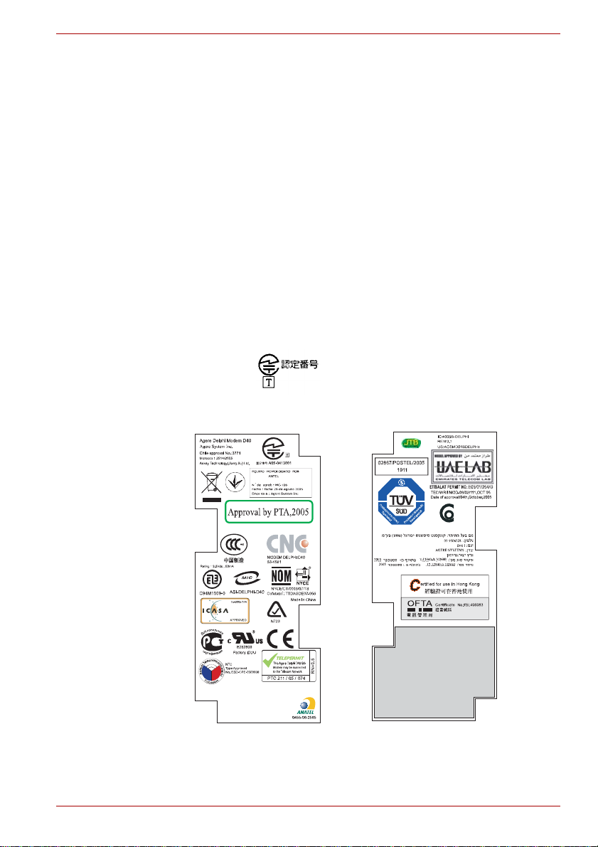
The internal modem is approved by the Japan Approvals Institute for
Telecommunications Equipment.
This label is located on the module.
Qosmio G40
A05-0413001
User’s Manual xii
Page 13

Pursuant to FCC CFR 47, Part 68:
When you are ready to install or use the modem, call your local telephone
company and give them the following information:
■ The telephone number of the line to which you will connect the modem
■ The registration number that is located on the device
The FCC registration number of the modem will be found on either the
device which is to be installed, or, if already installed, on the bottom of the
computer, separate from the system information label.
■ The Ringer Equivalence Number (REN) of the modem, which can vary -
for the REN, please refer to the modem's label.
The modem connects to the telephone line by means of a standard jack
called the USOC RJ11C.
Type of service
Your modem is designed to be used on standard-device telephone lines.
Connection to telephone company-provided coin service (central office
implemented systems) is prohibited. Connection to party lines service is
subject to state tariffs. If you have any questions about your telephone line,
such as how many pieces of equipment you can connect to it, the
telephone company will provide this information upon request.
Telephone company procedures
The goal of the telephone company is to provide you with the best service it
can. In order to do this, it may occasionally be necessary for them to make
changes in their equipment, operations, or procedures. If these changes
might affect your service or the operation of your equipment, the telephone
company will give you notice in writing to allow you to make any changes
necessary to maintain uninterrupted service.
Qosmio G40
If problems arise
If any of your telephone equipment is not operating properly, you should
immediately remove it from your telephone line, as it may cause harm to
the telephone network. If the telephone company notes a problem, they
may temporarily discontinue service. When practical, they will notify you in
advance of this disconnection. If advance notice is not feasible, you will be
notified as soon as possible. When you are notified, you will be given the
opportunity to correct the problem and informed of your right to file a
complaint with the FCC. In the event repairs are ever needed on your
modem, they should be performed by TOSHIBA Corporation or an
authorized representative of TOSHIBA Corporation.
Disconnection
If you should ever decide to permanently disconnect your modem from its
present line, please call the telephone company and let them know of this
change.
User’s Manual xiii
Page 14

Fax branding
The Telephone Consumer Protection Act of 1991 makes it unlawful for any
person to use a computer or other electronic device to send any message
via a telephone fax machine unless such a message clearly contains in a
margin at the top or bottom of each transmitted page, or on the first page of
the transmission, the date and time it is sent, an identification of the
business, other entity or individual sending the message and the telephone
number of the sending machine or such business, other entity or individual.
In order to program this information into your fax modem, you should
complete the setup of your fax software before sending messages.
Instructions for IC CS-03 certified equipment
1. The Industry Canada label identifies certified equipment. This
certification means that the equipment meets certain
telecommunications network protective, operational and safety
requirements as prescribed in the appropriate Terminal Equipment
Technical Requirements document(s). The Department does not
guarantee the equipment will operate to the user’s satisfaction.
Before installing this equipment, users should ensure that it is
permissible to be connected to the facilities of the local
telecommunications company. The equipment must also be installed
using an acceptable method of connection.
The customer should be aware that compliance with the above
conditions may not prevent degradation of service in some situations.
Repairs to certified equipment should be coordinated by a
representative designated by the supplier. Any repairs or alterations
made by the user to this equipment, or equipment malfunctions, may
give the telecommunications company cause to request the user to
disconnect the equipment.
Users should ensure for their own protection that the electrical ground
connections of the power utility, telephone lines and internal metallic
water pipe system, if present, are connected together. This precaution
may be particularly important in rural areas.
Qosmio G40
Users should not attempt to make such connections themselves, but
should contact the appropriate electric inspection authority, or electrician,
as appropriate.
2. The user manual of analog equipment must contain the equipment’s
Ringer Equivalence Number (REN) and an explanation notice similar to
the following:
The Ringer Equivalence Number (REN) of the modem can vary - for the
REN, please refer to the modem's label.
User’s Manual xiv
Page 15

The Ringer Equivalence Number (REN) assigned to each terminal device
provides an indication of the maximum number of terminals allowed to be
connected to a telephone interface. The termination on an interface may
consist of any combination of devices subject only to the requirement that
the sum of the Ringer Equivalence Numbers of all the devices does not
exceed 5.
3. The standard connecting arrangement (telephone jack type) for this
equipment is jack type(s): USOC RJ11C.
The IC registration number of the modem is shown below.
Canada: 4005B-DELPHI
Notes for Users in Australia and New Zealand
Modem warning notice for Australia
Modems connected to the Australian telecoms network must have a valid
Austel permit. This modem has been designed to specifically configure to
ensure compliance with Austel standards when the country/region
selection is set to Australia. The use of other country/region settings while
the modem is attached to the Australian PSTN would result in your modem
being operated in a non-compliant manner. To verify that the
country/region is correctly set, enter the command ATI which displays the
currently active setting.
To set the country/region permanently to Australia, enter the following
command sequence:
AT%TE=1
ATS133=1
AT&F
AT&W
AT%TE=0
ATZ
Failure to set the modem to the Australia country/region setting as shown
above will result in the modem being operated in a non-compliant manner.
Consequently, there would be no permit in force for this equipment, with
the Telecoms Act 1991 prescribing a penalty of $12,0 00 for the connection
of non-permitted equipm en t.
Qosmio G40
User’s Manual xv
Page 16

Notes for use of this device in New Zealand
■ The grant of a Telepermit for a device in no way indicates Telecom
acceptance of responsibility for the correct operation of that device
under all operating conditions. In particular the higher speeds at which
this modem is capable of operating depend on a specific network
implementation which is only one of many ways of delivering high
quality voice telephony to customers. Failure to operate should not be
reported as a fault to Telecom.
■ In addition to satisfactory line conditions a modem can only work
properly if:
a/ It is compatible with the modem at the other end of the call, and;
b/ the application using the modem is compatible with the application
at the other end of the call - for example, accessing the Internet
requires suitable software in addition to a modem.
■ This equipment shall not be used in any manner which could constitute
a nuisance to other Telecom customers.
■ Some parameters required for compliance with Telecom’s PTC
Specifications are dependent on the equipment (PC) associated with
this modem. The associated equipment shall be set to operate within
the following limits for compliance with Telecom Specifications:
a/ There shall be no more than 10 call attempts to the same number
within any 30 minute period for any single manual call initiation, and;
b/ The equipment shall go on-hook for a period of not less than 30
seconds between the end of one attempt and the beginning of the
next, and;
c/ Automatic calls to different numbers shall be not less than 5
seconds apart.
■ Immediately disconnect this equipment should it become physically
damaged, and arrange for its disposal or repair.
■ The correct settings for use with this modem in New Zealand are as
follows:
ATB0 (CCITT operation)
AT&G2 (1800Hz guard tone)
AT&P1 (decadic dialing make-break ratio =33%/67%)
ATS0=0 (disable auto answer)
ATS6=4 (blind dial delay)
ATS7=Less than 90 (time to wait for carrier after dialing)
ATS10=Less than 150 (loss of carrier to hangup delay - the factory
default of 15 is recommended)
ATS11=90 (DTMF dialing on/off duration in milliseconds)
ATX2 (dial tone detect, but not USA call progress detect)
Qosmio G40
User’s Manual xvi
Page 17

Qosmio G40
■ When used in Auto Answer mode, the S0 register must be set with to a
value of either 3 or 4. This ensures:
■ a person calling your modem will hear a short burst of ringing before
the modem answers. This confirms that the call has been
successfully switched through the network.
■ caller identification information (which occurs between the first and
second ring cadences) is not destroyed.
■ The preferred method of dialing is to use DTMF tones (ATDT...) as this
is faster and more reliable than pulse (decadic) dialing. If for some
reason you must use decadic dialing, your communications program
must be set up to record numbers using the following translation table
as this modem does not implement the New Zealand “Reverse Dialing”
standard.
Number to be dialed: 0 1 2 3 4 5 6 7 8 9
Number to program into computer: 0 9 8 7 6 5 4 3 2 1
Note that where DTMF dialing is used, the numbers should be
entered normally.
■ The transmit level from this device is set at a fixed level and because of
this there may be circumstances where the performance is less than
optimal. Before reporting such occurrences as faults, please check the
line with a standard Telepermitted telephone, and only report a fault if
the phone performance is impaired.
■ It is recommended that this equipment be disconnected from the
Telecom line during electrical storms.
■ When relocating the equipment, always disconnect the Telecom line
connection before the power connection, and reconnect the power first.
■ This equipment may not be compatible with Telecom Distinctive Alert
cadences and services such as FaxAbility.
NOTE THAT FAULT CALLOUTS CAUSED BY ANY OF THE ABOVE
CAUSES MAY INCUR A CHARGE FROM TELECOM
User’s Manual xvii
Page 18

General conditions
As required by PTC 100, please ensure that this office is advised of any
changes to the specifications of these products which might affect
compliance with the relevant PTC Specifications.
The grant of this Telepermit is specific to the above products with the
marketing description as stated on the Telepermit label artwork. The
Telepermit may not be assigned to other parties or other products without
Telecom approval.
A Telepermit artwork for each device is included from which you may
prepare any number of Telepermit labels subject to the general instructions
on format, size and color on the attached sheet.
The Telepermit label must be displayed on the product at all times as proof
to purchasers and service personnel that the product is able to be
legitimately connected to the Telecom network.
The Telepermit label may also be shown on the packaging of the product
and in the sales literature, as required in PTC 100.
The charge for a Telepermit assessment is $337.50. An additional charge
of $337.50 is payable where an assessment is based on reports against
non-Telecom New Zealand Specifications. $112.50 is charged for each
variation when submitted at the same time as the original.
An invoice for $NZ1237.50 will be sent under separate cover.
Following information is only for E U-member states:
Qosmio G40
The use of the symbol indicates that this product may not be treated as
household waste. By ensuring this product is disposed of correctly, you will
help prevent potential negative consequences for the environment and
human health, which could otherwise be caused by inappropriate waste
handling of this product. For more detailed information about recycling of
this product, please contact your local city office, your household waste
disposal service or the shop where you purchased the product.
This symbol may not stick depending on the country and region where you
purchased.
User’s Manual xviii
Page 19
Optical disc drive safety instructions
Be sure to check the international precautions at the end of this section.
TOSHIBA
HD DVD-ROM drive TS-L802A
■ The HD DVD-ROM drive employs a laser system. To ensure proper
use of this product, please read this instruction manual carefully and
retain for future reference.
Should the unit ever require maintenance, contact an authorized
service location.
■ Use of controls, adjustments or the performance of procedures other
than those specified may result in hazardous radiation exposure.
■ To prevent direct exposure to the laser beam, do not try to ope n the
enclosure.
Qosmio G40
User’s Manual xix
Page 20
TOSHIBA
HD DVD-R drive SD-L902A
■ The HD DVD-R drive employs a laser system. T o ensure proper use of
this product, please read this instruction manual carefully and retain for
future reference.
Should the unit ever require maintenance, contact an authorized
service location.
■ Use of controls, adjustments or the performance of procedures other
than those specified may result in hazardous radiation exposure.
■ To prevent direct exposure to the laser beam, do not try to ope n the
enclosure.
Qosmio G40
User’s Manual xx
Page 21
International precautions
Qosmio G40
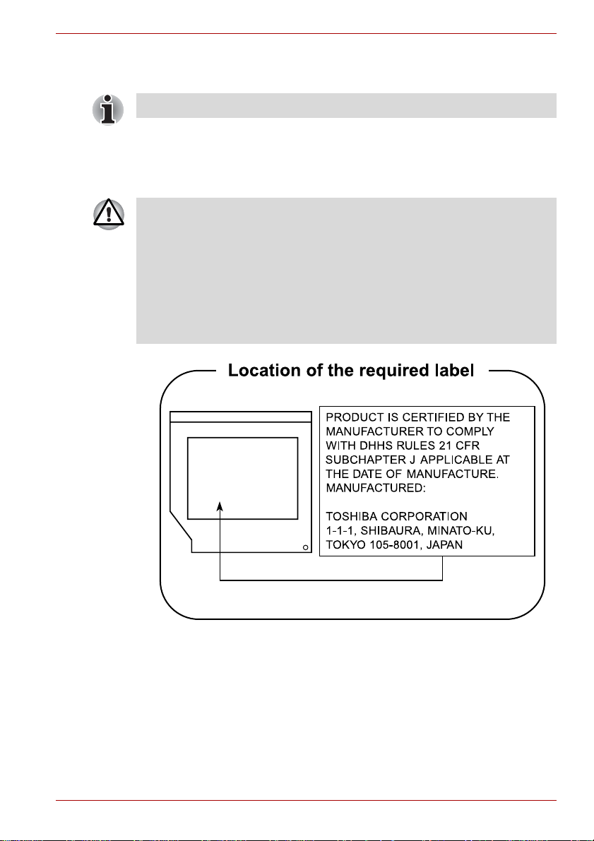
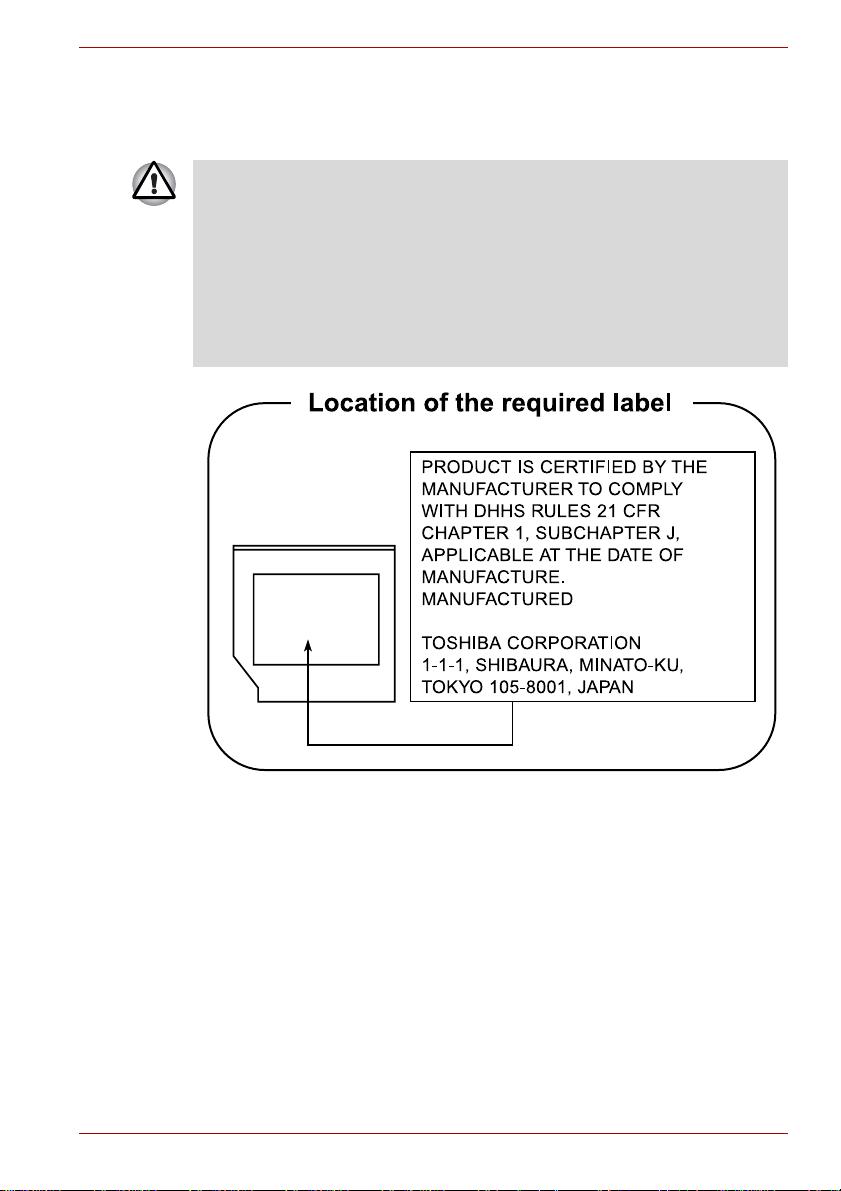
CAUTION: This appliance contains a
laser system and is classified as a
“CLASS 1 LASER PRODUCT.” To use
this model properly, read the instruction
manual carefully and keep this manual
for your future reference. In case of any
trouble with this model, please contact
your nearest “AUTHORIZED service
station.” To prevent direct exposure to
the laser beam, do not try to open the
enclosure.
VORSICHT: Dieses Gerät enthält ein
Laser-System und ist als
“LASERSCHUTZKLASSE 1 PRODUKT”
klassifiziert. Für den richtigen Gebrauch
dieses Modells lesen Sie bitte die
Bedienungsanleitung sorgfältig durch
und bewahren diese bitte als Referenz
auf. Falls Probleme mit diesem Modell
auftreten, benachrichtigen Sie bitte die
nächste “autorisierte Service-Vertretung”.
Um einen direkten Kontakt mit dem
Laserstrahl zu vermeiden darf das Gerät
nicht geöffnet werden.
User’s Manual xxi
ADVARSEL: Denne mærking er anbragt
udvendigt på apparatet og indikerer, at
apparatet arbejder med laserstråler af
klasse 1, hviket betyder, at der anvendes
laserstrlier af svageste klasse, og at man
ikke på apparatets yderside kan bilve
udsat for utilladellg kraftig stråling.
APPARATET BOR KUN ÅBNES AF
FAGFOLK MED SÆRLIGT KENDSKAB
TIL APPARATER MED
LASERSTRÅLER!
Indvendigt i apparatet er anbragt den her
gengivne advarselsmækning, som
advarer imod at foretage sådanne
indgreb i apparatet, at man kan komme til
at udsatte sig for laserstråling.
Page 22

Qosmio G40
OBS! Apparaten innehåller
laserkomponent som avger laserstråining
överstigande gränsen för laserklass 1.
VAROITUS. Suojakoteloa si saa avata.
Laite sisältää laserdiodin, joka lähetää
näkymätöntä silmilie vaarallista
lasersäteilyä.
CAUTION: USE OF CONTROLS OR
ADJUSTMENTS OR PERFORMANCE
OF PROCEDURES OTHER THAN
THOSE SPECIFIED IN THE OWNER’S
MANUAL MAY RESULT IN
HAZARDOUS RADIATION EXPOSURE.
VORSICHT: DIE VERWENDUNG VON
ANDEREN STEURUNGEN ODER
EINSTELLUNGEN ODER DAS
DURCHFÜHREN VON ANDEREN
VORGÄNGEN ALS IN DER
BEDIENUNGSANLEITUNG
BESCHRIEBEN KÖNNEN
GEFÄHRLICHE
STRAHLENEXPOSITIONEN ZUR
FOLGE HABEN.
User’s Manual xxii
Page 23

Preface
Congratulations on your purchase of the Qosmio G40 series computer.
This powerful notebook computer provides excellent expansion capability,
includes multimedia functionality, and is designed to provide years of
reliable, high-performance computing.
This computer family includes a model with a built-in TV tuner. When you
wish to display a TV program or play CD/DVD with this model before
Windows starts, touch the TV panel or the CD/DVD panel (or the same
panels on the remote control) respectively during Windows startup. When
Windows is running, you can display or record a TV program using the My
TV feature of Media Center.
This manual tells how to set up and begin using your Qosmio G40
computer. It also provides detailed information on configuring your
computer, basic operations and care, using optional devices and
troubleshooting.
If you are a new user of computers or if you’re new to portable computing,
first read over the Introduction and The Grand Tour chapters to familiarize
yourself with the computer’s features, components and accessory devices.
Then read Getting Started for step-by-step instructions on setting up your
computer.
If you are an experienced computer user, please continue reading the
preface to learn how this manual is organized, then become acquainted
with this manual by browsing through its pages. Be sure to read the Special
features section of the Introduction, to learn about features that are
uncommon or unique to this computer, as well as the section on HW Setup
& BIOS Setup, to understand how to setup and config ure these features.
If you are going to install PC Cards or connect external devices such as a
monitor, be sure to read Chapter 9, Optional Devices.
Conventions
This manual uses the following formats to describe, identify, and highlight
terms and operating procedures.
User’s Manual xxiii
Page 24

Abbreviations
On first appearance, and whenever necessary for clarity, abbreviations are
enclosed in parentheses following their definition. For example: Read Only
Memory (ROM). Acronyms are also defined in the Glossary.
Icons
Icons identify ports, dials, and other parts of your computer. Th e indicator
panel also uses icons to identify the components it is providing information
on.
Keys
The keyboard keys are used in the text to describe many computer
operations. A distinctive typeface identifies the key top symbols as they
appear on the keyboard. For example, ENTER identifies the ENTER key.
Key operation
Some operations require you to simultaneously use two or more keys. We
identify such operations by the key top symbols separated by a plus sign (+).
For example, CTRL + C means you must hold down CTRL and at the same
time press C. If three keys are used, hold down the first two and at the same
time press the third.
Qosmio G40
ABC
When procedures require an action such as
clicking an icon or entering text, the icon's name
or the text you are to type in is represented in the
typeface you see to the left.
Display
S
ABC
Names of windows or icons or text generated by
the computer that appear on its display screen
are presented in the type face you see to the left.
Messages
Messages are used in this manual to bring important information to your
attention. Each type of message is identified as shown below.
Pay attention! A caution informs you that improper use of equipment or
failure to follow instructions may cause data loss or damage your
equipment.
Please read. A note is a hint or advice that helps you make best use of
your equipment.
User’s Manual xxiv
Page 25

Indicates a potentially hazardous situation, which could result in death or
serious injury, if you do not follow instructions.
Terminology
This term is defined in this document as follows:
Qosmio G40
Start
The word "Start" refers to the " " button in
Microsoft® Windows VistaTM.
User’s Manual xxv
Page 26

General Precautions
TOSHIBA computers are designed to optimize safety, minimize strain and
withstand the rigors of portability. However, certain precautions should be
observed to further reduce the risk of personal injury or damage to the
computer.
Be certain to read the general precautions below and to note the cautions
included in the text of the manual.
Creating a computer-friendly environment
Place the computer on a flat surface that is large enough for the computer
and any other items you are using, such as a printer.
Leave enough space around the computer and other equipment to provide
adequate ventilation. Otherwise, they may overheat.
T o keep your computer in prime operating condition, protect your work area
from:
■ Dust, moisture, and direct sunlight.
■ Equipment that generates a strong electromagnetic field, such as
stereo speakers (other than speakers that are connected to the
computer) or speakerphones.
■ Rapid changes in temperature or humidity and sources of temperature
change such as air conditioner vents or heaters.
■ Extreme heat, cold, or humidity.
■ Liquids and corrosive chemicals.
Stress injury
Carefully read the Instruction Manual for Safety and Comfort. It contains
information on the prevention of stress injuries to your hands and wrists
that can be caused by extensive keyboard use. Instruction Manual for
Safety and Comfort also includes information on work space design,
posture and lighting that can help reduce physical stress.
User’s Manual xxvi
Page 27

Heat injury
■ Avoid prolonged physical contact with the computer. If the computer is
used for long periods, its surface can become very warm. While the
temperature will not feel hot to the touch, if you maintain physical
contact with the computer for a long time, for example if you rest the
computer on your lap or if you keep your hands on the palm rest, your
skin might suffer a low-heat injury.
■ If the computer has been used for a long time, avoid direct contact with
the metal plate supporting the various interface ports as this can
become hot.
■ The surface of the AC adaptor can become hot when in use but this
condition does not indicate a malfunction. If you need to transport the
AC adaptor, you should disconnect it and let it cool before moving it.
■ Do not lay the AC adaptor on a material that is sensitive to heat as the
material could become damaged.
Pressure or impact damage
Do not apply heavy pressure to the computer or subject it to any form of
strong impact as this can damage the computer's components or otherwise
cause it to malfunction.
PC Card overheating
Qosmio G40
Some PC Cards can become hot during prolonged use which may result in
errors or instability in the operation of the device in question. In addition,
you should also be careful when you remove a PC Card that has been
used for a long time.
Mobile phones
Please be aware that the use of mobile phones can interfere with the audio
system. The operation of the computer will not be impaired in any way, but
it is recommended that a minimum distance of 30cm is maintained between
the computer and a mobile phone that is in use.
Instruction Manual for Safety and Comfort
All important information on the safe and proper use of this computer is
described in the enclosed Instruction Manual for Safety and Comfort. Be
sure to read it before using the computer.
User’s Manual xxvii
Page 28
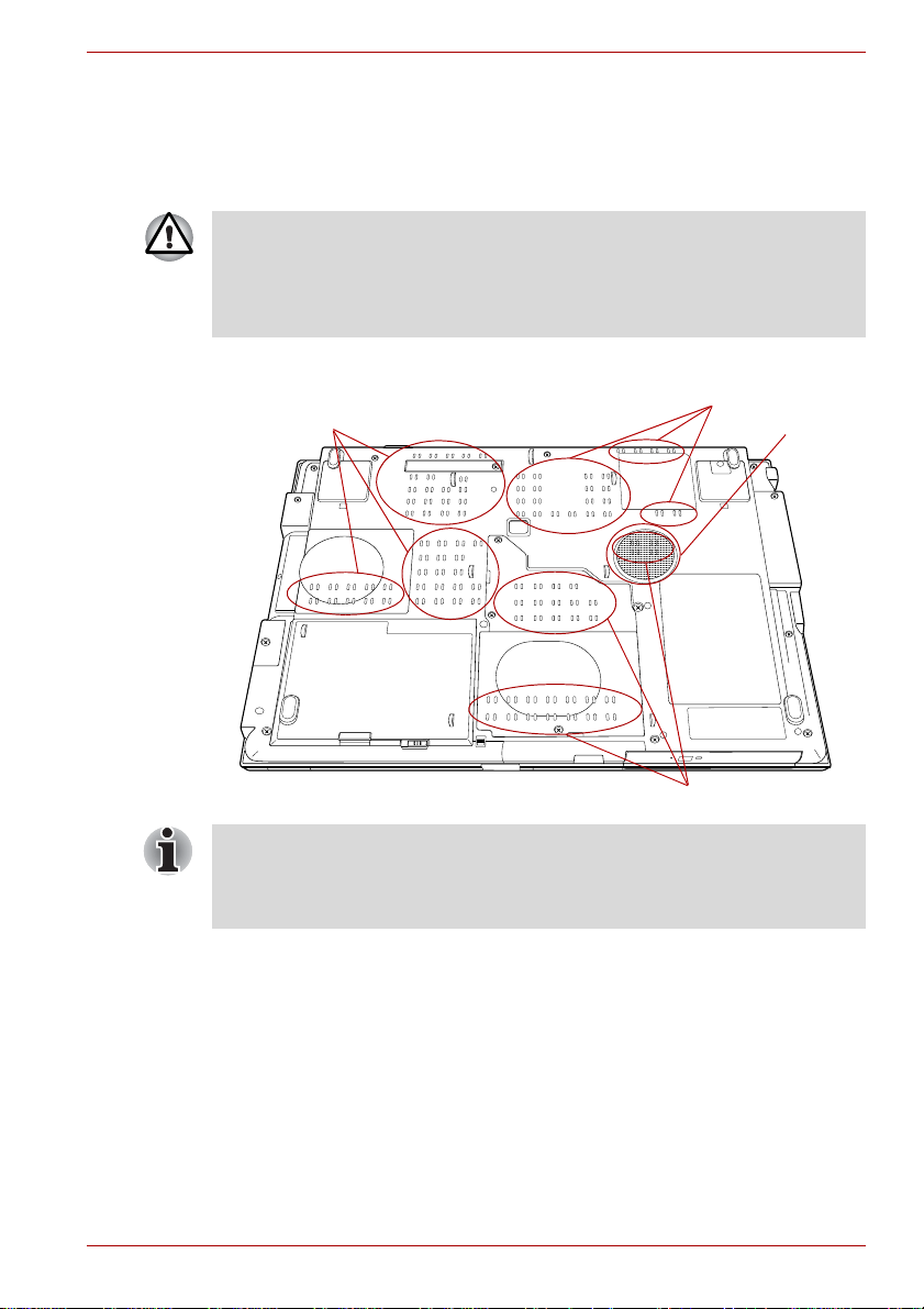
The cautions on use of a Qosmio G40 series computer
1. Clean any dust accumulated on the computer's cooling vents.
The cooling vents are located on the back and underside of the
computer.
When you use your computer in a dusty area, dirt and debris may
accumulate on the cooling vents at the under side of your unit. If this
occurs, the accumulated dust can cause insufficient heat dissipation which
may result in the computer shutting down during use. Carefully clean the
dust from the vents using a vacuum cleaner.
2. Cooling vents on the underside and back of the computer.
Qosmio G40
Cooling vents
Cooling vents
Cooling vents
Speaker
(subwoofer)
The above illustration is of the subwoofer equipped model. Models without
the subwoofer have cooling vents in the subwoofer location pictured
above. Models with the subwoofer do not have cooling vents in the
subwoofer location pictured above.
User’s Manual xxviii
Page 29

Qosmio G40
Cooling vents
Cooling vents
To prevent possible overheating of the CPU, make sure the cooling fan's
air intake is not blocked. The fan draws in air by creating a vacuum. If the
fan is blocked, it could cause the CPU to run at a lower performance level
or cause the computer to shut down. Loose items such as notebook and
tissue paper, plastic wrappers, or other similar materials can block the air
intake, preventing air from reaching the CPU. Do not use the computer on
surfaces with objects that can be drawn in by the cooling fan.
User’s Manual xxix
Page 30
Introduction
This chapter provides an equipment checklist, and it identifies the
computer’s features, options and accessories.
Some of the features described in this manual may not function properly if
you use an operating system that was not pre-installed by TOSHIBA.
Equipment checklist
Carefully unpack your computer, taking care to save the box and packaging
materials for future use.
Hardware
Check to make sure you have all the following items:
■ Qosmio G40 Portable Personal Computer
■ AC adaptor and power cord (2-pin plug or 3-pin plug)
■ Battery pack (Is pre-installed in some computer)
■ Modular cable (Is included with some models)
■ VIDEO-IN cable
■ Remote Controller
■ Infrared transmitter cable
■ Two AA manganese batteries (for Remote Controller)
Chapter 1
User’s Manual 1-1
Page 31

Documentation
■ Qosmio G40 Portable Personal Computer User’s Manual
(User’s Manual)
■ Qosmio HD DVD Guide
■ Instruction Manual for Safety and Comfort
■ End User License Agreement
If any of the items are missing or damaged, contact your dealer
immediately.
Software
The following Windows® operating system and utility software are preinstalled.
■ Microsoft
■ TOSHIBA Value Added Package
■ Ulead DVD MovieFactory
■ Fingerprint Utility
■ Windows Mobility Center
■ TOSHIBA Disc Creator
■ TOSHIBA Recovery Disc Creator
■ TOSHIBA ConfigFree
■ TOSHIBA Assist
■ TOSHIBA SD Memory Utilities
■ CD/DVD Drive Acoustic Silencer
■ TOSHIBA Password Utility
■ TOSHIBA HD DVD PLAYER
■ Online Manual
■ Qosmio G40 User’s Manual (This manual)
■ Discs
■ Windows Anytime Upgrade DVD (Is included with some models)
®
Windows Vista
TM
®
Introduction
Please refer to the included Qosmio HD DVD Guide for more information
on using the TOSHIBA HD DVD PLAYER.
User’s Manual 1-2
Page 32

Hardware
Introduction
This section describes the hardware of your computer.
The actual specifications may vary depending on the model you
purchased.
Processor
Built-in The computer is equipped with one of the
following Intel
■ Intel
incorporates 2MB Level-2 cache memory and
supports Enhanced Intel
®
processor.
®
CoreTM 2 Duo Processor, which
®
SpeedStep®
Technology.
®
■ Intel
CoreTM 2 Duo Processor, which
incorporates 4MB Level-2 cache memory and
supports Enhanced Intel
®
SpeedStep®
Technology.
Some models in this series use Intel® Centrino® Duo processor technology
which is based on three separate components, the Intel
processor, Intel
®
PRO/Wireless network connection and the Mobile Intel®
®
CoreTM 2 Duo
965 Express Chipset family.
Legal Footnote (CPU)*1
For more information on the CPU, please refer to the Legal Footnotes
section in Chapter 11 or Click the *1 above.
Memory
Slots 512, 1,024 or 2,048MB memory modules can be
installed in the computer's two memory slots for a
maximum of 4,096MB system memory.
This computer can be equipped with memory
modules of a maximum size of 4,096MB. The
actual amount of useable system memory will be
less than the installed memory modules.
User’s Manual 1-3
Page 33

Introduction
Video RAM The amount of Video RAM available is
dependent on the computer's system memory.
Start -> Control Panel -> Appearance and
Personalization -> Personalization -> Display
Settings.
The amount of Video RAM can be verified by
clicking the Advanced Settings... button in the
Display Settings window.
Legal Footnote (Memory (Main System))*2
For more information regarding Memory (Main System), please refer to the
Legal Footnotes section in Chapter 11 or click the *2 above.
Power
Battery pack The computer is powered by one rechargeable
lithium-ion battery pack.
Legal Footnote (Battery Life)*3
For more information regarding Battery Life, please refer to the Legal
Footnotes section in Chapter 11 or click the *3 above.
RTC battery The internal RTC battery backs up the Real Time
AC adaptor The AC adaptor provides power to the system
Clock and calendar.
and recharges the batteries when they are low. It
comes with a detachable power cord which will
either have a 2-pin or 3-pin plug enclosure.
As the AC adaptor is universal, it can receive a
range of AC voltages from 100 to 240 volts,
however you should note that the output current
varies among different models. Using the wrong
adaptor can damage your computer. Refer to the
AC adaptor section in Chapter 2, The Grand
Tour.
User’s Manual 1-4
Page 34

Disks
Introduction
Hard disk drive The following 6 types of hard disk drives can be
installed in this computer. The capacity of each
hard disk drive model is different.
■ 80.0 billion bytes (74.53 GB)
■ 100.0 billion bytes (93.16 GB)
■ 120.0 billion bytes (111.79 GB)
■ 160.0 billion bytes (149.05 GB)
■ 200.0 billion bytes (186.32 GB)
■ 250.0 billion bytes (232.90 GB)
Two computer models are available, a model
with a single hard disk drive and a model with two
hard disk drives.
Please note that part of the hard disk drive's
overall capacity is reserved as administration
space.
Legal Footnote (Hard Disk Drive (HDD) Capacity)*4
For more information regarding Hard Disk Drive (HDD) Capacity, plea se
refer to the Legal Footnotes section in Chapter 11 or click the *4 above.
User’s Manual 1-5
Page 35

Optical disc drive
Introduction
HD DVD-ROM drive Some models are equipped with a full-size HD
DVD-ROM drive module that lets you run CD's or
DVD's without using an adaptor. The drive reads
DVD-ROM's at a maximum 8x speed and CDROM's at a maximum 24x speed, and HD DVD's
at a maximum 1x speed and writes CD-R's at up
to 16x speed, CD-RW's at up to 10x speed, DVDR's and DVD+R's at up to 4x speed, DVD-RW's
and DVD+RW's at up to 4x speed, DVD-R (Dual
layer) at up to 2x speed, DVD+R (Double Layer)
at up to 2.4x speed and DVD-RAM at up to 3x
speed, and supports the following formats:
■ CD-R
■ CD-RW
■ DVD-ROM
■ DVD-Video
■ CD-DA
■ CD-Text
■ Photo CD™ (single/multi-session)
■ CD-ROM Mode 1, Mode 2
■ CD-ROM XA Mode 2 (Form1, Form2)
■ Enhanced CD (CD-EXTRA)
■ Addressing Method 2
■ DVD-R
■ DVD-R (Dual Layer)
■ DVD-RW
■ DVD+R
■ DVD+R (Double Layer)
■ DVD+RW
■ DVD-RAM
■ HD DVD-ROM
User’s Manual 1-6
Page 36

Introduction
HD DVD-R drive Some models are equipped with a full-size HD
DVD-R drive module that lets you run CD's or
DVD's without using an adaptor.
The drive reads DVD-ROM's at a maximum 8x
speed and CD-ROM's at a maximum 24x speed,
and HD DVD's at a maximum 1x speed and
writes CD-R's at up to 16x speed, CD-RW's at up
to 10x speed, DVD-R's and DVD+R's at up to 4x
speed, DVD-RW's and DVD+RW's at up to 4x
speed, DVD-R (Dual layer) at up to 2x speed,
DVD+R (Double Layer) at up to 2.4x speed and
DVD-RAM at up to 3x speed, HD DVD-R at up to
1x speed, and supports the following formats in
addition to HD DVD-ROM drive:
■ HD DVD-R
The optical drive installed on this computer cannot write multiple sessions
on HD DVD-R Dual Layer disc sessions. Once a disc has been written to
once, it will be finalized. Once finalized, no further writing to the disc will be
possible regardless of what portion of the total disc capacity was used.
Legal Footnote (General HD DVD technology and
playback)
For more information regarding the General HD DVD technology and
playback, please refer to the Legal Footnotes section in Chapter 11 or click
the *5 above.
*5
Display
The computer's internal display panel supports high-resolution video
graphics and can be set to a wide range of viewing angles for maximum
comfort and readability.
Built-in 17" TFT LCD screen, 32 million colors, with a
resolution of 1920 horizontal x 1200 vertical
pixels WUXGA.
Legal Footnote (LCD)*6
For more information regarding the LCD, please refer to the Legal
Footnotes section in Chapter 11 or click the *6 above.
Graphics controller Graphics controller maximizes display
User’s Manual 1-7
performance. Refer to Display Controller and
Video modes section in Appendix B for more
information.
Page 37

Introduction
Legal Footnote (Graphics Processor Unit ("GPU"))*7
For more information regarding the Graphics Processor Unit ("GPU"),
please refer to the Legal Footnotes section in Chapter 11 or click the *7
above.
Keyboard
Built-in The internal keyboard provides the embedded
numeric overlay keys, dedicated cursor control
overlay keys, and Keys. The keyboard
is compatible with the IBM
Refer to Chapter 5, The Keyboard, for details.
®
enhanced keyboard.
Pointing Device
Built-in Touch Pad The integr ated Touch Pad and control buttons in
Qosmio AV
Controller
the palm rest allow control of the on-screen
pointer and support functions such as the
scrolling of windows.
This button allows you to operate the Media
Center.
Ports
External monitor The analog VGA port provides support for VESA
DDC2B compatible functions.
Universal Serial Bus
(USB 2.0)
i.LINK™ (IEEE1394) This port allows high-speed data transfer to take
The computer supports multiple Universal Serial
Bus ports that comply with the USB 2.0 standard.
place between the computer and external
devices such as digital video cameras.
Slots
PC Card The internal PC Card slot accommodates a
single Type II (5mm) card.
ExpressCard The internal ExpressCard slot is a Universal slot.
This slot supports ExpressCard/54 and
ExpressCard/34 modules.
Bridge media This slot lets you insert SD/SDHC memory card,
miniSD/microSD Card, Memory Stick (PRO/PRO
Duo), xD picture card and MultiMediaCard. Refer
to Chapter 9, Optional Devices.
User’s Manual 1-8
Page 38

Multimedia
Introduction
Sound system The integrated sound system provides support
for the computer's internal speakers and
microphone, as allowing an external microphone
and headphones to be connected via the
appropriate jacks.
Web Camera Web Camera is a device that allows you to
record video or take photographs with your
computer. You can use it for video chatting or
video conferences using a communication tool
such as Windows Live Messenger. Camera
Assistant Software will help you to add various
video effects to your video or photograph.
Please refer to the Web Camera section in
Chapter 4, Operating Basics.
TV antenna port Connect the antenna cable to this port to watch
TV programs on your computer or record them.
The dimensions and shape of the TV antenna
port vary for different regions.
S-Video-in Port A camcorder or other recording device can be
connected to this port via the S-Video-in cable
(optional) for importing video data. Refer to the
S-Video-in section in Chapter 9, Optional
Devices.
S-Video out port This S-Video out port lets you transfer NTSC or
PAL data to external devices. Refer to the TV
section in Chapter 9, Optional Devices.
VIDEO-IN port With the bundled VIDEO-IN cable, the CATV or
satellite set top boxes can be connected to the
computer to view the channels.
Please refer to Chapter 8, Connecting the
VIDEO-IN port for details on how to connect the
computer with the VIDEO-IN cable.
HDMI out port HDMI out port can connect with Type A
connector HDMI cable.
One HDMI cable can send and receive video,
audio and control signals.
Headphone (S/PDIF)
jack
This jack lets you connect digital speakers or a
stereo headphone (16 ohm minimum). When you
connect a digital speaker or headphones, the
internal speaker is automatically disabled.
This jack can be used also as S/PDIF jack and
enables connection of optical digital
correspondence apparatus.
User’s Manual 1-9
Page 39

Headphone jack A 3.5mm mini headphone jack enables
connection of stereo headphones or powered
speakers.
Introduction
Microphone jack A 3.5mm mini microphone jack enables
connection of a three-conductor microphone for
monaural input.
Line-in jack A standard 3.5 mm mini line-in jack enables
connection of a stereo device for audio input.
Built-in TV Tuner Built-in TV Tuner enables watching and
recording TV programs. Some models are
capable of simultaneously recording 2 different
television programs.
Infrared receiver
window
This is a sensor window that receives signals
from the Remote Controller which is provided
with your computer.
Infrared transmitter
cable port
Connect the Infrared transmitter cable to this
port.
Connecting the set top box or other external
device to the computer using the infrared
transmitter cable allows the external device to be
operated using the computer and specialized
remote control.
Remote Controller Use this device to navigate when watching TV or
playing CDs/DVDs/HD DVDs.
Communications
Modem Some models are equipped with the integrated
modem. The integrated modem provides
capability for data and fax communications that
support the V.90 (V.92) standards and includes a
modem jack for connection to the telephone line.
Please note that both the V.90 and V.92
standards are only supported in the USA,
Canada, United Kingdom, France, Germany and
Australia - only the V.90 standard is supported in
other regions. You should also be aware that the
speed of data and fax transfer will depend on the
analog telephone line conditions.
The integrated model is only installed as a
standard device in some markets. Please refer to
the V.90 section in Appendix E for more
information.
User’s Manual 1-10
Page 40

Introduction
LAN The computer has built-in support for Ethernet
LAN (10 megabits per second, 10BASE-T), Fast
Ethernet LAN (100 megabits per second,
100BASE-TX) and Gigabit Ethernet LAN (1000
megabits per second, 1000BASE-T).
It is pre-installed as a standard device in some
markets.
Bluetooth Some computers in this series offer Bluetooth
wireless communication functionality which
eliminates the need for cables between
electronic devices such as computers and
printers. When implemented, Bluetooth provides
a fast, reliable and secure means to achieve
wireless communication in a small space.
Wireless LAN Some computers in this series are equipped with
a Wireless LAN card that is compatible with other
LAN systems based on Direct Sequence Spread
Spectrum/Orthogonal Frequency Division
Multiplexing radio technology that complies with
the IEEE 802.1 1 Standard (Revision A, B, G or N
Draft Ver. 1.0).
■ The transmission speed over the wireless LAN and the distance over
which wireless LAN can reach may vary depending on surrounding
electromagnetic environment, obstacles, access point design and
configuration, and client design and software/hardware configurations.
The Tr ansmit Rate (at X Mbit/s) is the theoretical maximum speed
under the IEEE802.11 (a/b/g) st andard. The actual transmission speed
will be lower than the theoretical maximum speed.
■ The Wake-up on Wireless LAN function is effective only when it is
connected with an Access Point. This function becomes invalid when
the connection is broken.
Legal Footnote (Wireless LAN)*8
For more information regarding Wireless LAN, please refer to the Legal
Footnotes section in Chapter 11 or click the *8 above.
Wireless
communication
switch
This switch turns the Wireless LAN and Bluetooth
functions on and off. Please note that all models
are provided with a Wireless communication switch
and some models are equipped with both Wirele ss
LAN and Bluetooth functionality.
User’s Manual 1-11
Page 41

Security
Introduction
Security lock slot Connects a security lock to anchor the computer
Special features
The following features are either unique to TOSHIBA computers or are
advanced features which make the computer more convenient to use.
Access each function using the following procedures.
*1 To access the Power Options, click Start -> Control Panel -> System
and Maintenance -> Power Options.
Hot keys Hot keys are specific key combinations that let
Display automatic
power off
HDD automatic
power off
System automatic
Sleep/Hibernation
*1
Mode
Keypad overlay A ten-key numeric keypad is integrated into the
Power on password Two levels of password security, supervisor and
Instant security A specific hot key function automatically locks the
to a desk or other large object.
you quickly change the system configuration
directly from the keyboard without running a
system program.
This feature automatically cuts off power to the
*1
computer's display panel when there is no
keyboard input for a specified time, with pow e r
being restored the next time a key is pressed.
This can be specified in the Power Options.
This feature automatically cuts off power to the
*1
hard disk drive when it is not accessed for a
specified time, with power being restored when
the hard disk drive is next accessed. This can be
specified in the Power Options.
This feature automatically shuts down the system
into either Sleep Mode or Hibernation Mode when
there is no input or hardware access for a
specified time. This can be specified in the Power
Options.
keyboard. Please refer to the Keypad overlay
section in Chapter 5, The Keyboard, for
information on using this feature.
user, are available to prevent unauthorized
access to your computer.
system providing data security.
User’s Manual 1-12
Page 42

Introduction
Intelligent power
supply
*1
A microprocessor in the computer's intelligent
power supply detects the battery's charge,
automatically calculates the remaining battery
capacity and protects electronic components
from abnormal conditions such as a voltage
overload from the AC adaptor. This can be
specified in the Power Options.
*1
Battery save mode
This feature lets you configure the computer in
order to save battery power. This can be
specified in the Power Options.
Panel power on/off
*1
This feature automatically turns power to the
computer off when the display panel is closed,
and turns it back on when the display panel is
opened. This can be specified in the Power
Options.
Low battery
automatic
Hibernation Mode
When battery power is exhausted to the point that
computer operation cannot be continued, the
*1
system automatically enters Hibernation Mode
and shuts itself down. This can be specified in the
Power Options.
Heat dispersal
*1
To protect against overheating, the processor
has an internal temperature sensor so that, if the
computer's internal temperature rises to a certain
level, the cooling fan is turned on or the
processing speed is lowered. This can be
specified in the Power Options.
Hibernation Mode This feature lets you turn of f the power to the
computer without exiting from your software. The
contents of main memory are automatically
saved to the hard disk drive so that when you
next turn the power on again, you can continue
working right where you left off. Refer to the
Turning off the power section in Chapter 3,
Getting Started, for more details.
Sleep Mode If you have to interrupt your work, you can use
this feature to allow you to turn off power to the
computer without exiting from your software.
Data is maintained in the computer's main
memory so that when you next turn on the power,
you can continue working right where you left off.
User’s Manual 1-13
Page 43

TOSHIBA Value Added Package
This section describes the TOSHIBA Component features pre-installed on
the computer.
Introduction
TOSHIBA Power
Saver
TOSHIBA Button
Support
TOSHIBA Zooming
Utility
TOSHIBA PC
Diagnostic Tool
TOSHIBA Password
Utility
TOSHIBA Flash
Cards
TOSHIBA Power Saver provides you with the
features of more various power supply
managements.
This utility controls the following computer panel
functions.
The applications associated with each of the
following panels can be assigned by the user.
■ Panels: Assign applications to the REC,
Brightness, Illumination On/Off, DOLBY, TVout panels.
This utility allows you to enlarge or reduce the
icon size on the Windows Desktop, or the zoom
factor associated with specific supported
applications.
The TOSHIBA PC Diagnostic Tool will display
basic system configuration information and allow
the functionality of some of the computer's builtin hardware devices to be tested.
The TOSHIBA Password utility allows you to set
a password in order to restrict access to the
computer.
The TOSHIBA Flash Cards provide a quick wa y
to modify selected system functions and to
launch applications.
■ Hot key function
■ TOSHIBA utility launcher function
HW Setup This utility allows you to customize your
TOSHIBA
Accessibility
User’s Manual 1-14
hardware settings according to the way you work
with the computer and the peripherals you use.
The TOSHIBA Accessibility utility provides
support to movement impaired users when they
need to use the TOSHIBA Hot-key functions. In
use, the utility allows you to make the FN key
'sticky', that is you can press it once, release it,
and they press one of the 'F' keys in order to
access its specific function. When set, the FN
key will remain active until another key is
pressed.
Page 44

Utilities and Applications
This section describes the pre-installed utilities that come with the
computer and details how to start them. For further information on their
operation, please refer to each utility's online manual, help files or
README.TXT file.
Fingerprint Utility This product has a fingerprint utility installed for
Bluetooth Stack for
Windows by Toshiba
Introduction
the purpose of enrolling and recognizing
fingerprints which can then be linked to a
username and password in order to remove the
need to input these details from the keyboard.
Just by swiping an enrolled finger against the
fingerprint sensor, the following functions will be
enabled:
■ Logon to Windows and access a security
enabled homepage through Internet Explorer.
■ Files and folders can be encrypted/decrypted
and third party access to them is prevented.
■ Disable the password-protected screen-saver
when returning from a power-saving mode
such as Sleep Mode.
■ Authentication of the User Password (and, if
applicable, the HDD(Hard Disk Drive)
Password) when booting up the computer
(Power-on Security).
■ Single Sign-on feature
This software enables communication between
the computer and external Bluetooth devices
such as printers and mobile phones.
Bluetooth functions cannot be used in models that do not have a Bluetooth
module installed.
TOSHIBA Assist TOSHIBA Assist is a graphical user interface that
provides access to specific tools, utilities and
applications that make the use and configuration
of the computer easier.
TOSHIBA ConfigFree TOSHIBA ConfigFree is a suite of utilities that
User’s Manual 1-15
improve the ease and control of communication
devices and network connections, help in the
identification of communication problems and
allow the creation of profiles if you need to switch
between different locations and communication
networks. To access this utility, click Start -> All
Programs -> TOSHIBA -> Networking ->
ConfigFree.
Page 45

Introduction
TOSHIBA Disc
Creator
TOSHIBA DVD-RAM
Utility
Ulead DVD
MovieFactory for
TOSHIBA
TOSHIBA SD
Memory Card Format
Windows Mobility
Center
TOSHIBA HD DVD
PLAYER
You can create CD's an d DVD's in a number of
formats including audio CD's that can be played
on a standard CD player, and data CD's/DVD's
which can store copies of the files and folders on
your computer's hard disk drive. This software
can be used on models with either a HD DVDROM drive or a HD DVD-R drive.
To access this utility, click Start -> All Programs
-> TOSHIBA -> CD&DVD Applications -> Disc
Creator.
TOSHIBA DVD-RAM Utility has the function of
Physical Format and Write-Protect to DVD-RAM.
This utility is contained the setup module of
TOSHIBA Disc Creator. To access this utility,
click Start -> All Programs -> TOSHIBA ->
CD&DVD Applications -> DVD-RAM Utility.
Ulead DVD MovieFactory for TOSHIBA allows
users to instantly create DVD video or slideshow
discs via a user-friendly wizard interface with
specific task oriented featur es.
This utility allows you to format an SD memory
card by the SD standard format.
This section describes the Windows Mobility
Center. Mobility Center is a utility for accessing
several mobile PC settings quickly in one
window. A default maximum of eight tiles are
provided by the operating system, and the
additional two tiles are added to your Mobility
Center.
■ Lock Computer:
This can be used to lock your computer without
turning it off. This has the same function as the
Lock button at the bottom of the right pane in the
start menu.
■ TOSHIBA Assist:
This can be used to open TOSHIBA Assist if it is
already installed in your computer.
This software is provided for playba ck of HD
DVD Video.
Please refer to the included Qosmio HD DVD
Guide for more information on using the
TOSHIBA HD DVD PLAYER.
User’s Manual 1-16
Page 46

Introduction
Options
CD/DVD Drive
Acoustic Silencer
The CD/DVD Drive Acoustic Silencer utility
allows you to configure the read speed at which
the optical disc drive will operate. In use you can
select either Normal Mode, which will operate
the drive at its maximum speed for quick data
access, or Quiet Mode, which operates the drive
at single speed for audio CD playback and which
can lessen the operational noise. This utility does
not have any function when using DVD's.
You are able to add a number of options and accessories in order to make
your computer even more powerful and convenient to use. For reference,
the following list details some of the items that are available from your
reseller or TOSHIBA dealer:
Memory expansion A 512MB, 1,024MB or 2,048MB memory module
(DDR2-667) can easily be installed in the
computer.
Battery Pack An additional battery pa ck can be purchased for
use as either a spare or replacement. Please
refer to Chapter 6, Power for futher information.
Universal AC
Adaptor
If you frequently use your computer at more than
one site, it may be convenient to purchase an
additional AC adaptor to be kept at each site in
order to remove the need to always carry the
adaptor with you.
USB FDD kit The USB floppy diskette drive accommodates
either a 1.44MB or 720KB floppy diskette through
connection to one of the computer's USB ports.
In use, please be aware that, while you cannot
format 720KB floppy diskettes under Windows
TM
Vista
, you are able to read and write to
diskettes that have already been formatted.
Battery Charger The optional battery charger allows you to
charge extra battery packs outside of having to
use the computer.
Bluetooth USB
Adaptor
A Bluetooth adaptor that has a USB connector.
Wireless communications can be carried out with
Bluetooth-compatible equipment by connecting
to the USB port of the computer.
You can buy the module from a TOSHIBA dealer.
User’s Manual 1-17
Page 47

Introduction
Bluetooth Wireless
Mouse
Bluetooth Wireless
Stereo
The Bluetooth Wireless Mouse is a wireless
optical mouse compatible with Bluetooth.
You can buy the Bl uetooth Wireless Mouse from
a TOSHIBA dealer.
The Bluetooth Wireless Stereo is a wireless
stereo headphone set compatible with Bluetooth.
You can buy the Bl uetooth Wireless Stereo from
a TOSHIBA dealer.
User’s Manual 1-18
Page 48

The Grand Tour
This chapter identifies the various components of your computer. Become
familiar with each component before you operate the computer.
Legal Footnote (Non-applicable Icons)*9
For more information regarding Non-applicable Icons, please refer to the
Legal Footnotes section in Chapter 11 or click the *9 above.
Front with the display closed
The following figures show the computer’s front with its display panel in the
closed position.
System indicators
Chapter 2
Display latch
HD DVD-ROM drive or HD DVD-R drive
Figure 2-1 Front of the computer with display closed
HD DVD-ROM drive The computer is configured with a HD DVD-ROM
drive.
HD DVD-R drive The computer is configured with a HD DVD-R
drive.
The computer is equipped with one of the following optical disc drive.
■ HD DVD-ROM drive
■ HD DVD-R drive
User’s Manual 2-1
Infrared receiver window
Page 49

Left side
The Grand Tour
System indicators These LED indicators allow you to monitor the
status of various computer functions and are
described in more detail within the System
indicators section.
Display latch This latch secures the display panel in its closed
position - push the latch in order to open the
display for use.
Infrared receiver
window
This is a sensor window that receives signals
from the remote control which is provided with
your computer.
The following figure shows the computer's left side.
Bridge media slot
Security lock slot
Universal Serial Bus
(USB 2.0) port
Wireless communication switch
i.LINK (IEEE1394) port
ExpressCard slot
PC Card slot
Figure 2-2 The left side of the computer
PC Card eject
button
ExpressCard
eject button
Universal Serial Bus
(USB 2.0) port
Security lock slot A security cable can be attached to this slot and
then connected to a desk or other large object in
order to deter theft of the computer.
ExpressCard slot This slot allows you to install a single
ExpressCard device.
ExpressCard eject
button
This button is used in order to remove an
ExpressCard from within the computer.
PC Card slot This slot can accommodate a single Type II, 16-
bit or 32-bit (CardBus) PC Card device.
PC Card eject button This button is used in order to remove a PC Card
from within the computer.
User’s Manual 2-2
Page 50

The Grand Tour
Keep foreign metal objects, such as screws, staples and paper clips, out of
the ExpressCard slot and PC Card slot. Foreign metal objects can create a
short circuit, which can cause damage and fire, possibly resulting in
serious injury.
Universal Serial Bus
(USB 2.0) ports
Two Universal Serial Bus ports, which comply
with the USB 2.0 standard, are provided on the
left hand side of the computer. The ports with the
icon ( ) has USB Sleep and Charge function.
Keep foreign metal objects, such as screws, staples and paper clips, out of
the USB connectors. Foreign metal objects can create a short circuit,
which can cause damage and fire, possibly resulting in serious injury.
Please note that it is not possible to confirm the operation of all functions of
all USB devices that are available. In view of this it may be noted that
some functions associated with a specific device might not operate
properly.
Bridge media slot This slot lets you insert an SD/SDHC memory
card, miniSD/microSD Card, Memory Stick
(PRO/PRO Duo), xD picture card and
MultiMediaCard. Refer to Chapter 9, Optional
Devices.
Keep foreign metal objects, such as screws, staples and paper clips, out of
the Bridge media slot. Foreign metal objects can create a short circuit,
which can cause damage and fire, possibly resulting in serious injury.
Wireless
communication
switch
Slide this switch to the right to turn off Wireless
LAN and Bluetooth functions. Slide it to the left to
turn on the functions.
All models are provided with a Wireless
communication switch although only some
models are equipped with both Wireless LAN
and Bluetooth functions.
User’s Manual 2-3
Page 51

The Grand Tour
■ Turn Wi-Fi® and Bluetooth functionalities off when near a person who
may have a cardiac pacemaker implant or other medical electric
device. Radio waves may affect pacemaker or medical device
operation, possibly resulting in serious injury. Follow the instruction of
your medical device when using any Wi-Fi or Bluetooth functionality.
■ Always turn off Wi-Fi or Bluetooth functionality if the computer is near
automatic control equipment or appliances such as automatic doors or
fire detectors. Radio waves can cause malfunction of such equipment,
possibly resulting in serious injury.
■ Do not use the Wi-Fi or Bluetooth functionalities near a microwave
oven or in areas subject to radio interference or magnetic fields.
Interference from a microwave oven or other source can disrupt Wi-Fi
or Bluetooth operation.
Right side
i.LINK (IEEE1394)
port
This port allows you to connect an external
device, such as a digital video camera, to the
computer for high-speed data transfer.
The following figure shows the computer’s right side.
Line-in jack
Headphone (S/PDIF)
jack
Headphone jack
Universal Serial Bus
(USB 2.0) port
Microphone jack
Figure 2-3 The right side of the computer
Modem jack (Some models are
equipped with a built-in modem)
VIDEO-IN port
S-Video-in port
Headphone jack A 3.5 mm mini headphone jack enables
connection of stereo headphones.
Headphone (S/PDIF)
jack
This jack lets you connect digital speakers or a
stereo headphone (16 ohm minimum). When you
connect a digital speaker or headphones, the
internal speaker is automatically disabled.
This jack can be used also as S/PDIF jack and
enables connection of optical digital
correspondence apparatus.
User’s Manual 2-4
Page 52

The Grand Tour
Microphone jack A 3.5 mm mini microphone jack enables
connection of a three-conductor mini jack for
monaural microphone input.
Line-in jack A standard 3.5 mm mini line-in jack enables
connection of a stereo device for audio input.
Universal Serial Bus
(USB 2.0) port
The Universal Serial Bus port, which complies
with the USB 2.0 standard, is provided on the
right side of the computer.
Modem jack The modem jack allows you use to attach a
modular cable in order to connect the internal
modem directly to a telephone line.
Some models are equipped with a built-in
modem.
■ Connection to any communication line other than an analog phone line
could cause a computer system failure.
■ Connect the built-in modem only to ordinary analog phone lines.
■ Never connect the built-in modem to a digital line (ISDN).
■ Never connect the built-in modem to the digital connector on a
public telephone or to a digital private branch exchange (PBX).
■ Never connect the built-in modem to a key telephone system for
residences or offices.
■ Never operate your computer on AC power during a thunderstorm. If
you see lightning or hear thunder, immediately turn off the computer.
An electric surge caused by the storm, may result in a system failure,
loss of data or hardware damage.
VIDEO-IN port With the bundled VIDEO-IN cable, the CATV or
satellite set top boxes can be connected to the
computer to view the channels.
Please refer to Chapter 8, AV functions for
details on how to connect the computer with the
VIDEO-IN cable.
S-Video-in port A camcorder or other recording device can be
connected to your computer via the S-Video-in
cable for importing video data. Connect the cable
to this port for this operation. Refer to the S-
Video-in section in Chapter 9, Optional Devices.
User’s Manual 2-5
Page 53

Back
The Grand Tour
The following figure shows the computer’s back.
Infrared transmitter
cable ports
TV antenna port
DC IN 15V jack
S-Video out port
Universal Serial Bus
(USB 2.0) ports
External monitor port
Cooling vents
Figure 2-4 The back of the computer
LAN active indicator
(orange)
HDMI out port
Link indicator
(green)
LAN jack
TV antenna port Connect the antenna cable to this port to watch
TV programs on your computer or record them.
The dimensions and shape of the TV antenna
port vary for different regions.
DC IN 15V jack The AC adaptor connects to this jack in order to
power the computer and charge its internal
batteries. Please note that you should only use
the model of adaptor supplied with the computer
at the time of purchase - using the wrong adaptor
can cause damage to the computer.
Cooling vents The computer's cooling vents help keep the
processor from overheating.
Do not block the cooling vents. Keep foreign metal objects, such as
screws, staples and paper clips, out of the cooling vents. Foreign metal
objects can create a short circuit, which can cause damage and fire,
possibly resulting in serious injury.
Infrared transmitter
cable ports
Connect the infrared transmitter cable to the
infrared transmitter cable port on the computer
and to the set-top box.
S-Video out port The S-Video out port supports the connection of
an optional S-Video cable to attach the computer
to a television or similar device.
Universal Serial Bus
(USB 2.0) ports
Two Universal Serial Bus ports, which comply
with the USB 2.0 standard, are provided on the
back of the computer.
User’s Manual 2-6
Page 54

The Grand Tour
External monitor
port
This port allows you to connect an external video
display to the computer.
HDMI out port HDMI out port can connect with Type A
connector HDMI cable.
One HDMI cable can send and receive video,
audio and control signals.
LAN jack This jack lets you connect to a LAN. The adaptor
has built-in support for Ethernet LAN (10
megabits per second, 10BASE-T), Fast Ethernet
LAN (100 megabits per second, 100BASE-TX)
and Gigabit Ethernet LAN (1000 megabits per
second, 1000BASE-T). The LAN has two
indicators. Refer to Chapter 4, Operating Basics,
for details.
■ Do not connect any cable other than a LAN cable to the LAN jack. It
could cause damage or malfunction.
■ Do not connect the LAN cable to a power supply. It could cause
damage or malfunction.
Link indicator
(green)
LAN active
indicator (orange)
This indicator glows green when the computer is
connected to a LAN and the LAN is functioning
properly.
This indicator glows orange when data is being
exchanged between the computer and the LAN.
User’s Manual 2-7
Page 55

Underside
The following figure shows the underside of the computer. You should
ensure that the display is closed before the computer is turned over to
avoid causing any damage.
Memory module slots
The Grand Tour
Speaker
(subwoofer)
Battery pack
Battery release latch
Figure 2-5 The underside of the computer
Battery safety lock
The above illustration is of the subwoofer equipped model. Models without
the subwoofer have cooling vents in the subwoofer location pictured
above. Models with the subwoofer do not have cooling vents in the
subwoofer location pictured above.
Memory module
slots
The memory module slots are located here. The
memory module slots allow for the installation,
replacement and removal of additional memory
modules. Please refer to the Memory expansion
section in Chapter 9, Optional Devices for more
information.
Battery safety lock Slide this latch into its 'Unlock' position in order to
release the battery pack ready for removal.
Battery release
latch
Slide and hold this latch into its 'Unlock' position
in order to release the battery pack ready for
removal.
For more detailed information on removing the
battery pack please refer to Chapter 6, Power.
User’s Manual 2-8
Page 56

Battery pack The battery pack provides power to the computer
S
(
Speaker (subwoofer) The subwoofer will reproduce of the low
Front with the display open
This section shows the computer with the display panel open. In order to
open the display, simply push the display latch on the front of the computer ,
lift the display panel up and position it at a comfortable viewing angle for
you.
Web Camera LED
Microphone
Display screen
tereo speaker
tweeter left)
Display hinge
Stereo speaker
(Left)
The Grand Tour
when the AC adaptor is not connected. For more
detailed information on the use and operation of
the battery pack please refer to Chapter 6,
Power.
frequency sounds generated. Some models are
equipped with a subwoofer.
Web Camera
Stereo speaker
(tweeter right)
Display hinge
Stereo speaker
(Right)
Qosmio AV
Controller
Fingerprint
Sensor
LCD Sensor switch
(Not shown)
Power button
Volume control dial
Front operation panel
(eleven panels)
Touch Pad
Touch Pad
control buttons
Figure 2-6 The front of the Touch Pad model with the display open
Display hinge The display hinges allow the display panel to be
position at a variety of easy-to-view angles.
User’s Manual 2-9
Page 57

The Grand Tour
Stereo speakers The speakers will reproduce all of the sounds
generated through the installed software,
together with any alarms, such as that
accompanying a low battery condition, that are
generated by the system.
Keep foreign objects out of the speakers. Never allow metal objects, such
as screws, staples and paper clips, to enter the computer or keyboard.
Foreign metal objects can create a short circuit, which can cause computer
damage and fire, possibly resulting in serious injury.
Speakers (tweeter) The tweeter will reproduce of the high-frequency
sounds generated.
Display screen The internal screen displays high-contrast text
and graphics images up to the maximum
resolution supported by the model in question.
For example, an WUXGA compatible model will
support resolutions between 800x600 and
1920x1200 pixels.
Please be aware that, when the computer is
operating on the AC adaptor, the image
displayed on the internal screen will be
somewhat brighter than when it operates on
battery power. This difference in brightness
levels is intended to save power when operating
on batteries. For more information on the
computer's display, please refer to the Display
Controller and Video modes section in Appendix
B.
Front operation
panel (eleven
panels)
Eleven panels are available for use:
TV, CD/DVD, Play/Pause, Stop, Previous, Next,
Record, Brightness, Illumination On/Off, DOLBY,
TV-out.
These panels allow you to manage Audio/Video,
run applications and access utilities.
Refer to Chapter 8, AV functions for details.
Power button Press this button to turn the computer's power on
and off. The Power button will glow blue when
the computer's power is on.
To uc h Pa d The Touch Pad mouse control device located in
the center of the palm rest is used to control the
movement of the on-screen pointer. For more
information, please refer to the Using the Touch
Pad section in Chapter 4, Operating Basics.
User’s Manual 2-10
Page 58

The Grand Tour
To uc h Pa d co ntrol
buttons
The control buttons located below the T ouch Pad
allow you to select menu items or manipulate text
and graphics as designated by the on-screen
pointer.
Fingerprint Sensor
Just by swiping a valid and enrolled finger against
the fingerprint sensor, the following functions will be
enabled:
■ Logon to Windows and access a security
enabled homepage through Internet Explorer.
■ Files and folders can be encrypted/decrypted
and third party access to them prevented.
■ Disable the password-protected screen-saver
when returning from a power-saving mode
such as Sleep Mode.
■ Power-on security and single sign-on
facilities.
Web Camera Web Camera is a device that allows you to
record video or take photographs with your
computer. You can use it for video chatting or
video conferences using a communication tool
such as Windows Live Messenger. Camera
Assistant Software will help you to add various
video effects to your video or photograph.
Enables the transmission of video and use of
video chat via the internet using specialized
applications.
The effective pixel count for this web camera is
1.92 million.
Please refer to the Web Camera section in
Chapter 4, Operating Basics.
Web Camera LED
The Web Camera LED lights up when the Web
Camera is operating.
Qosmio AV
Controller
This button allows you to operate the Media
Center.
Please refer to the Qosmio AV Controller section
in Chapter 8, AV functions for more information.
User’s Manual 2-11
Page 59

The Grand Tour
LCD Sensor switch This switch senses when the display panel is
either closed or opened and activates the Panel
Power Off/On feature as appropriate. For
example, when you close the display panel the
computer enters Hibernation Mode and shuts
itself down and then, when you next open the
display, the computer will automatically start up
and return you to the application you were
previously working on.
You can specify within the Power Options. To
access it, click Start -> Control Panel ->
System and Maintenance -> Power Options.
Do not put any magnetic objects close to this switch as they may cause the
computer to automatically enter Hibernation Mode and shut down even if
the Panel Power Off feature is disabled.
Volume control dial Use this dial to adjust the volume of the internal
stereo speakers and optional external stereo
headphones (if connected).
Turn the dial clockwise to increase the volume
and turn it counter-clockwise to decrease the
volume.
Microphone A built-in microphone allows you to import and
record sounds for your applications - please refer
to the Sound system section in Chapter 4,
Operating Basics for more information.
System indicators
The LED system indicators for specific computer operations glow when
those operations are in progress.
Figure 2-7 System indicators
DC IN The DC IN indicator normally glows blue when
User’s Manual 2-12
power is being correctly supplied from the AC
power adaptor. However, If the output voltage
from the adaptor is abnormal, or if the computer's
power supply malfunctions, this indicator will
flash orange.
Page 60

The Grand Tour
Power The Power indicator normally glows blue when
the computer is turned on. However, if you turn
the computer off into Sleep Mode, this indicator
will flash orange - approximately one second on,
two seconds off - both while the system is
shutting down and while it remains turned off.
Battery The Battery indicator shows the condition of the
battery's charge - blue indicates the battery is
fully charged, orange indicates the battery is
charging, and flashing orange indicates a low
battery condition. Please refer to Chapter 6,
Power for more information on this feature.
Hard Disk Drive The Hard Disk Drive indicator glows blue
whenever the computer is accessing the built-in
hard disk drive.
Optical Disc Drive The Optical Disc Drive indicator glows blue
when the computer is accessing a disc in the
optical disc drive.
Bridge media slot The Bridge media slot indicator glows blue
when the computer is accessing the Bridge
media slot.
Wireless
communication
The Wireless communication indicator glows
orange when the Bluetooth and wireless LAN
functions are turned on.
All models are provided with a Wireless
Communication switch although only some
models are equipped with both Wireless LAN
and Bluetooth functions.
User’s Manual 2-13
Page 61

Keyboard indicators
The following figures show the positions of the CAPS LOCK indicator and
the keypad overlay indicators which show the following conditions:
■ When the CAPS LOCK indicator glows, the keyboard will produce
capitals when any letter is typed.
■ When the Arrow Mode indicator glows, the keypad overlay allows you
to use cursor functions.
■ When the Numeric Mode indicator glows, the keypad overlay allows
you to enter numbers.
CAPS LOCK indicator
The Grand Tour
Arrow Mode
indicator
Numeric Mode
indicator
Figure 2-8 Keypad indicators
CAPS LOCK This indicator glows green when letter keys are
locked into their uppercase format.
Arrow Mode When the Arrow Mode indicator lights green,
you can use the gray labeled keys on the keypad
overlay as cursor keys. Please refer to the
Keypad overlay section in Chapter 5, The
Keyboard for more information.
Numeric Mode When the Numeric Mode indicator lights green,
you can use the gray labeled keys on the keypad
overlay for number entry. Please refer to the
Keypad overlay section in Chapter 5, The
Keyboard for more information.
User’s Manual 2-14
Page 62

Optical disc drives
One of the following optical disc drives is provided in the computer: HD
DVD-ROM and HD DVD-R drives. This optical drive uses an ATAPI
interface controller for CD and DVD operation and has an indicator at its
front which will glows to indicate that it is in use.
For further information on loading and unloading discs, please refer to the
Using HD DVD-ROM drive an d HD D V D-R drives section in Chapter 4,
Operating Basics.
Region codes for DVD drives and media
HD DVD-ROM drive, HD DVD-R drives and their associated media are
manufactured according to the specifications of six marketing regions.
When you purchase DVD Video media you should ensure that it matches
the specification of your drive, otherwise it will not play properly.
Code Region
1 Canada, United States
2 Japan, Europe, South Africa, Middle East
3 South East Asia, East Asia
4 Australia, New Zealand, Pacific Islands, Central
The Grand Tour
America, South America, Caribbean
5 Russia, Indian Subcontinent, Africa, North Korea,
Mongolia
6 China
Writab le discs
This section describes the types of writable CD, DVD and HD DVD media
available, and should be used in conjunction with the specification of your
computer/optical drive in order to understand the type of discs that can be
written. Please refer to Chapter 4, Operating Basics for further information.
CDs
■ CD-R media can only be written to once - the recorded data cannot
subsequently be erased or changed.
■ CD-RW media, including multi-speed CD-RW discs, high-speed CD-
RW discs and ultra-speed CD-RW discs, can be recorded to more than
once.
User’s Manual 2-15
Page 63

DVDs
■ DVD-R, DVD+R, DVD-R (Dual Layer) and DVD+R (Double Layer)
media discs can only be written to once - the recorded data cannot
subsequently be erased or changed.
■ DVD-RW, DVD+RW and DVD-RAM media can be recorded to more
than once.
HD DVDs
■ HD DVD-R and HD DVD-R (Dual Layer) media discs can only be
written to once - the recorded data cannot subsequently be erased or
changed.
Formats
The drives support the following formats:
■ CD-ROM
■ DVD-ROM
■ DVD-R
■ DVD-R (Dual Layer)
■ DVD-RW
■ DVD+R
■ DVD+R (Double
Layer)
■ DVD+RW
■ DVD-RAM
■ DVD-Video
■ CD-R
■ CD-RW
■ CD-DA
■ CD-Text
■ CD-ROM XA Mode 2
(Form1, Form2)
■ CD-ROM Mode 1,
Mode 2
■ Photo CD™
(single/multi-session)
■ Enhanced CD (CD-
EXTRA)
■ Addressing Method 2
■ HD DVD-ROM
(Single-sided SingleLayer)
■ HD DVD-ROM
(Single-sided DualLayer)
■ HD DVD (Twin format
disc)
■ HD DVD-Video
The Grand Tour
Some types and formats of DVD-R (Dual Layer) and DVD+R (Double
Layer) discs may be unreadable.
User’s Manual 2-16
Page 64

HD DVD-ROM drive
The full-size HD DVD-ROM module allows you to record data to recordable
CD's and DVD's as well as run either 12cm (4.72") CD's, DVD's and HD
DVD's, and 8cm (3.15") CD's and DVD's without using an adaptor.
The speed is slower at the center of a disc and faster at the outer edge.
HD DVD read 1 speed (maximum)
DVD read 8 speed (maximum)
DVD-R write 4 speed (maximum)
DVD-R (Dual Layer) write 2 speed (maximum)
DVD-RW write 4 speed (maximum)
DVD+R write 4 speed (maximum)
DVD+R (Double Layer) write 2.4 speed (maximum)
DVD+RW write 4 speed (maximum)
DVD-RAM write 3 speed (maximum)
CD read 24 speed (maximum)
CD-R write 16 speed (maximum)
CD-RW write 10 speed (maximum,
Ultra-speed media)
The Grand Tour
User’s Manual 2-17
Page 65

HD DVD-R drive
The optical drive installed on this computer cannot write multiple sessions
on HD DVD-R Dual Layer disc sessions. Once a disc has been written to
once, it will be finalized. Once finalized, no further writing to the disc will be
possible regardless of what portion of the total disc capacity was used.
The full-size HD DVD-R module allows you to record data to recordable
CD's and DVD's as well as run either 12cm (4.72") CD's, DVD's and HD
DVD's, and 8cm (3.15") CD's and DVD's without using an adaptor.
The speed is slower at the center of a disc and faster at the outer edge.
HD DVD read 1 speed (maximum)
HD DVD-R write 1 speed (maximum)
HD DVD-R (Dual Layer) write 1 speed (maximum)
DVD read 8 speed (maximum)
DVD-R write 4 speed (maximum)
DVD-R (Dual Layer) write 2 speed (maximum)
DVD-RW write 4 speed (maximum)
DVD+R write 4 speed (maximum)
DVD+R (Dual Layer) write 2.4 speed (maximum)
DVD+RW write 4 speed (maximum)
DVD-RAM write 3 speed (maximum)
CD read 24 speed (maximum)
CD-R write 16 speed (maximum)
CD-RW write 10 speed (maximum,
Ultra-speed media)
The Grand Tour
User’s Manual 2-18
Page 66

AC adaptor
The AC adaptor can automatically adjust to any voltage ranging from 100
to 240 volts and to a frequency of either 50 or 60 hertz, enabling you to use
this computer in almost any country/region. The adaptor converts AC
power to DC power and reduces the voltage supplied to this computer.
To recharge the battery, simply connect the AC adaptor to a power source
and to the computer. Please refer to Chapter 6, Power for further
information.
The Grand Tour
Figure 2-9 The AC adaptor (2-pin plug)
Figure 2-10 The AC adaptor (3-pin plug)
■ Depending on the model in question, either a 2-pin or 3-pin
adaptor/power lead will be bundled with the computer.
■ Do not use a 3-pin to 2-pin conversion plug.
■ The supplied power cord conforms to safety rules and regulations in
the region the product is bought and should not be used outside of this
region. In order to use the adaptor/computer in other regions, you
should please buy a power cord that conforms to the safety rules and
regulations in that particular region.
Always use the TOSHIBA AC adaptor that was provided with your
computer and the TOSHIBA Battery Charger (that may have been
provided with your computer), or use AC adaptors and battery chargers
specified by TOSHIBA to avoid any risk of fire or other damage to the
computer. Use of an incompatible AC adaptor or Battery Charger could
cause fire or damage to the computer possibly resulting in serious injury.
User’s Manual 2-19
Page 67

Getting Started
This chapter provides basic information to start using your computer. It
covers the following topics:
■ All users should be sure to read the section Starting up for the first
time.
■ Be sure to read the enclosed Instruction Manual for Safety and Comfort
for information on the safe and proper use of this computer. It is
intended to help you be more comfortable and productive while using a
notebook computer. By following the recommendations in it you may
reduce your chance of developing a painful or disabling injury to your
hand, arms, shoulders or neck.
■ Connecting the AC adaptor
■ Opening the display
■ Turning on the power
■ Starting up for the first time
■ Turning off the power
■ Restarting the computer
■ Creating Optical Recovery Discs
■ Restoring the pre-installed software from the Recovery hard disk drive
■ Restoring the pre-installed software from your created Recovery Discs
Chapter 3
■ Use a virus-check program and make sure it is updated regularly.
■ Never format storage media without checking its content. Formatting
destroys all stored data.
■ It is a good idea to periodically back up the internal hard disk drive or
other main storage device to external media. General storage media is
not durable or stable over long periods of time and under certain
conditions may result in data loss.
■ Before you install a device or application, save any data in memory to
the hard disk drive or other storage media. Failure to do so may result
in the loss of data.
User’s Manual 3-1
Page 68

Connecting the AC adaptor
Attach the AC adaptor when you need to charge the battery or you want to
operate from AC power. It is also the fastest way to get started, because
the battery pack will need to be charged before you can operate from
battery power.
The AC adaptor can be connected to any power source supplying from 100
to 240 volts and 50 or 60 hertz. For details on using the AC adaptor to
charge the battery pack, refer to Cha pt er 6 , Power.
■ Always use the TOSHIBA AC adaptor that was provided with your
computer and the TOSHIBA Battery Charger (that may have been
provided with your computer), or use AC adaptors and battery chargers
specified by TOSHIBA to avoid any risk of fire or other damage to the
computer. Use of an incompatible AC adaptor or Battery Charger could
cause fire or damage to the computer possibly resulting in serious
injury. T OSHIBA assumes no liability for any damage caused by use of
an incompatible adaptor or Battery Charger.
■ Never plug the AC adaptor or Battery Charger into a power source that
does not correspond to both the voltage and the frequency specified on
the regulatory label of the unit. Failure to do so could result in a fire or
electric shock, possibly resulting in serious injury.
■ Always use or purchase power cables that comply with the legal
voltage and frequency specifications and requirements in the country
of use. Failure to do so could result in a fire or electric shock, possi bly
resulting in serious injury.
■ The supplied power cord conforms to safety rules and regulations in
the region the product is bought and should not be used outside this
region. For use in other regions, please buy power cords that conform
to safety rules and regulations in the particular region.
■ Do not use a 3-pin to 2-pin conversion plug.
■ When you connect the AC adaptor to the computer, always follow the
steps in the exact order as described in the User’s Manual. Connecting
the power cable to a live electrical outlet should be the last step
otherwise the adaptor DC output plug could hold an electrical charge
and cause an electrical shock or minor bodily injury when touched. As
a general safety precaution, avoid touching any metal parts.
■ Never place your computer or AC adaptor on a wooden surface,
furniture, or any other surface that could be marred by exposure to heat
since the computer base and AC adaptor's surface increase in
temperature during normal use.
■ Always place your computer or AC adaptor on a flat and hard surface
that is resistant to heat damage.
Refer to the enclosed Instruction Manual for Safety and Comfort for
detailed precautions and handling instructions.
Getting Started
User’s Manual 3-2
Page 69

Getting Started
1. Connect the power cord to the AC adaptor.
Figure 3-1 Connecting the power cord to the AC adaptor (2-pin plug)
Figure 3-2 Connecting the power cord to the AC adaptor (3-pin plug)
Either a 2-pin or 3-pin adaptor/cord will be included with the computer
depending on the model.
2. Connect the AC adaptor's DC output plug to the DC IN 15V jack on the
back of the computer.
DC IN 15V jack
Figure 3-3 Connecting the adaptor to the computer
3. Plug the power cord into a live wall outlet - the Battery and DC IN
indicators on the front of the computer should glow.
User’s Manual 3-3
Page 70

Opening the display
The computer's display panel can be opened to a wide range of angles for
optimal viewing.
1. Push the display latch on the front of the computer to unlatch the
display panel.
2. While holding down the palm rest with one hand so that the main body
of the computer is not raised, slowly lift the display panel - this will allow
the angle of the display panel to be adjusted to provide optimum clarity.
Display panel
Getting Started
Display latch
Figure 3-4 Opening the display
Use reasonable care when opening and closing the display panel.
Opening it vigorously or slamming it shut could damage the computer.
User’s Manual 3-4
Page 71

Getting Started
■ As the display panel cannot be opened until 180 degrees, please be
careful of the angle when flipping open the display panel.
■ Be careful not to open the display panel too far as this could put stress
on the display panel’s hinges and cause damage.
■ Do not press or push on the display panel.
■ Do not lift the computer by the displ ay panel.
■ Do not close the display panel with pens or any ot he r ob j ects left in
between the display panel and the keyboard.
■ When opening or closing the display panel, place one hand on the
palm rest to hold the computer in place and use the other hand to
slowly open or close the display panel (Do not use excessive force
when opening or closing the display panel).
Turning on the power
This section describes how to turn on the power - the Power indicator will
then indicate the status. Please refer to the Power indicators section in
Chapter 6, Power for more information.
■ After you turn on the power for the first time, do not turn it off until you
have set up the operating system. Please refer to the section Starting
up for the first time for more information.
■ Volume cannot be adjusted during Windows Setup.
1. Open the computer's display panel.
User’s Manual 3-5
Page 72

2. Press and hold the computer's power button for two or three seconds.
Power button
Figure 3-5 Turning on the power
Starting up for the first time
The Microsoft Windows VistaTM Startup Screen will be the first screen
displayed when you turn on the power. Follow the on-screen instructions on
each screen in order to properly install the operating system.
When it is displayed, be sure to read the Software License Terms
carefully.
Turning off the power
Getting Started
The power can be turned off in one of three modes, either Shut Down
(Boot) Mode, Hibernation Mode or Sleep Mode.
Shut Down mode (Boot Mode)
When you turn off the power in Shut Down Mode no data will be saved and
the computer will boot to the operating system's main screen the next time
it is turned on.
1. If you have entered data, either save it to the hard disk drive or to other
storage media.
2. Make sure all disk/disc activity has stopped before removing the
CD/DVD/HD DVD or floppy diskette.
■ Make sure the Hard Disk Drive indicator is off. If you turn off the power
while a disk (disc) is being accessed, you may lose data or damage the
disk.
■ Never turn off the power while an application is running. Doing so could
cause loss of data.
■ Never turn off the power, disconnect an external storage device or
remove storage media during data read/write. Doing so can cause data
loss.
3. Click St art.
User’s Manual 3-6
Page 73

4. Click the arrow button ( ) located in the power management buttons
( ) and select Shut Down from the menu.
5. Turn off any peripheral devices connected to your computer.
Do not turn the computer or peripheral devices back on immediately - wait
a short period to avoid any potential damage.
Sleep Mode
If you have to interrupt your work, you are able to turn off the power without
exiting from your software by placing the computer into Sleep Mode. In this
mode data is maintained in the computer's main memory so that, when you
turn on the power again, you can continue working right where you left off.
Turning Off Your Computer where Electronic Devices are Regulated or
Controlled.
When you have to turn off your computer aboard an aircraft or in places
where electronic devices are regulated or controlled, always shut down the
computer completely or put the computer into Hibernation Mode instead of
allowing it to go into Sleep Mode, and turn off any wireless communication
switches or devices, while in Sleep Mode, the computer operating system
may reactivate itself to run pre-programmed tasks or to preserve unsaved
data, and might interfere with aviation or other systems, possibly causing
serious injury.
Getting Started
■ Before entering Sleep Mode, be sure to save your data.
■ Do not install or remove a memory module while the computer is in
Sleep Mode. The computer or the memory module could be damaged.
■ Do not remove the battery pack while the computer is in Sleep Mode
(unless the computer is connected to an AC power source). Data in
memory could be lost.
■ When the AC adaptor is connected, the computer will go into Sleep
Mode according to the settings in the Power Options (to access it, Start
-> Control Panel -> System and Maintenance -> Power Options).
■ To restore the operation of the computer from Sleep Mode, press and
hold the power button or any key on the keyboard for a short amount of
time. Please note that keyboard keys can only be used if the Wake-up
on Keyboard option is enabled within the HW Setup utility.
■ If the computer enters Sleep Mode while a network application is
active, the application might not be restored when the computer is next
turned on and the system returns from Sleep Mode.
■ To prevent the computer from automatically entering Sleep Mode,
disable Sleep Mode within the Power Options (to access it, Start ->
Control Panel -> System and Maintenance -> Power Options).
■ To use the Hybrid Sleep function, configure it in the Power Options.
User’s Manual 3-7
Page 74

Getting Started
Benefits of Sleep Mode
The Sleep Mode feature provides the following benefits:
■ Restores the previous working environment more rapidly than does the
Hibernation Mode feature.
■ Saves power by shutting down the system when the computer receives
no input or hardware access for the time period set by the System
Sleep Mode feature.
■ Allows the use of the panel power off feature.
Executing Sleep Mode
You can also enable Sleep Mode by pressing FN + F3 - please refer to
Chapter 5, The Keyboard, for further details.
You can enter Sleep Mode in one of four ways:
■ Click Start then click the power button ( ) located in the power
management buttons ( ).
Please note that this feature must be enabled within the Power Options
(to access it, click Start -> Control Panel -> System and Maintenance
-> Power Options).
■ Click Start then click the arrow button ( ) and select Sleep from the
menu.
■ Close the display panel. Please note that this feature must be enabled
within the Power Options (to access it, click Start -> Control Panel ->
System and Maintenance -> Power Options).
■ Press the power button. Please note that this feature must be enabled
within the Power Options (to access it, click Start -> Control Panel ->
System and Maintenance -> Power Options).
When you turn the power back on, you can continue where you left when
you shut down the computer.
■ When the computer is in Sleep Mode, the Power indicator will blink
orange.
■ If you are operating the computer on battery power, you can lengthen
the overall operating time by turning it off into Hibernation Mode - Sleep
Mode will consume more power while the computer is off.
Sleep Mode limitations
Sleep Mode will not function under the following conditions:
■ Power is turned back on immediately after shutting down.
■ Memory circuits are exposed to static electricity or electrical noise.
User’s Manual 3-8
Page 75

Hibernation Mode
The Hibernation Mode feature saves the contents of memory to the hard
disk drive when the computer is turned off so that, the next time it is turned
on, the previous state is restored. Please note that the Hibernation Mode
feature does not save the status of any peripheral devices connected to the
computer.
■ Save your data. While entering Hibernation Mode, the computer saves
the contents of memory to the hard disk drive. However, for safety
sake, it is best to save your data manually.
■ Data will be lost if you remove the battery or disconnect the AC adaptor
before the save is completed. Wait for the Hard Disk Drive indicator to
go out.
■ Do not install or remove a memory module while the computer is in
Hibernation Mode. Data will be lost.
Benefits of Hibernation Mode
The Hibernation Mode feature pro vi des the following benefits:
■ Saves data to the hard disk drive when the computer automatically
shuts down because of a low battery condition.
■ Y ou can return to your previous working environment immediately when
you turn on the computer.
■ Saves power by shutting down the system when the computer receives
no input or hardware access for the time period set by the System
Hibernate feature.
■ Allows the use of the panel power off feature.
Getting Started
Starting Hibernation Mode
You can also enable Hibernation Mode by pressing FN + F4 - please refer
to Chapter 5, The Keyboard, for further details.
To enter Hibernation Mode, follow the steps below.
1. Click St art.
2. Click the arrow button ( ) in the power management buttons
( ) and select Hibernate from the menu.
Automatic Hibernation Mode
The computer can be configured to enter Hibernation Mode automatically
when you press the power button or close the lid. In order to define these
settings, you can follow the steps as described below:
1. Click St art and click the Control Panel.
2. Click System and Maintenance and click Power Options.
3. Click Choose what the power button does or Choose what closing
the lid does.
User’s Manual 3-9
Page 76

4. Enable the desired Hibernation Mode settings for When I press the
power button and When I close the lid.
5. Click the Save changes button.
Data save in Hibernation Mode
When you turn off the power in Hibernation Mode, the computer will take a
moment to save the current data in memory to the hard disk drive. During
this time, the Hard Disk Drive indicator will glow.
After you turn off the computer , and the content of memory has been saved
to the hard disk drive, turn off the power to any peripheral devices.
Do not turn the computer or devices back on immediately. Wait a moment
to let all capacitors fully discharge.
Restarting the computer
Certain conditions require that you reset the computer, for example if:
■ You change certain computer settings.
■ An error occurs and the computer does not respond to your keyboard
commands.
If you need to restart the computer, there are three ways this can be
achieved:
■ Click Start then click the arrow button ( ) in the power management
buttons ( ) and select Restart from the menu.
■ Press CTRL, ALT and DEL simultaneously (once) to display the menu
window, then select Restart from the Shut down options.
■ Press the power button and hold it down for five seconds. Once the
computer has turned itself off, wait between ten and fifteen seconds
before turning the power on again by pressing the power button.
Getting Started
System Recovery Options
About 1.5GB hidden partition is allocated on the hard disk drive for the
System Recovery Options.
This partition stores files which can be used to repair the system in the
event of a problem.
The System Recovery Options feature will be unusable if this partition is
deleted.
User’s Manual 3-10
Page 77

System Recovery Options
The System Recovery Options feature is installed on the hard disk when
shipped from the factory. The System Recovery Options menu includes
tools to repair startup problems, run diagnostics or restore the system.
See the Windows Help and Support content for more information about
Startup Repair.
The System Recovery Options can also be run manually to repair
problems.
The procedure is as follows. Follow the instructi ons shown on the onscreen menu.
1. Turn off the computer.
2. While holding the F8 key, turn on the computer.
3. The Advanced Boot Options menu will be displayed.
Use the arrow keys to select Repair Your Computer and press
ENTER.
4. Follow the on-screen instructions.
The Windows VistaTM CompletePC Backup feature can be used on
Windows Vista
System Recovery
This section describes the method of system recovery.
TM
Business Edition and Ultimate Edition.
Getting Started
Creating Optical Recovery Discs
This section describes how to create Recovery Discs.
■ Be sure to connect the AC adaptor when you create Recovery Discs.
■ Be sure to close all other software programs except the Recovery Disc
Creator.
■ Do not run software such as screen savers which can put a heavy load
on the CPU.
■ Operate the computer at full power.
■ Do not use power-saving features.
■ Do not write to the disc when the virus check software is running. Wait
for it to finish, then disable virus detection programs including any
software that checks files automatically in the background.
■ Do not use utilities, including those intended to enhance hard disk drive
access speed. They may cause unstable operation and damage data.
■ Do not shut down/log off or Sleep/Hibernate while writing or rewriting
the disc.
■ Set the computer on a level surface and avoid places subjected to
vibrations such as airplanes, trains, or cars.
■ Do not use on unstable tables or other any other unstable surfaces.
User’s Manual 3-11
Page 78

Getting Started
A recovery image of the software on your computer is stored on the hard
disk drive, and can be copied to DVD media by using the following steps:
1. Select either blank DVD media.
2. The application will allow you to choose from a variety of different media
onto which the recovery image can be copied including DVD-R, DVD-R
DL, DVD-RW, DVD+R, DVD+R DL and DVD+RW.
Please note that some of the above media may not be compatible with the
optical disc drive installed into your computer. You should therefore verify
the optical disc drive supports the blank media you have chosen before
proceeding.
3. Turn on your computer and allow it to load the Windows VistaTM
operating system from the hard disk drive as normal.
4. Insert the first blank media into the optical disc drive tray .
5. Double click the Recovery Disc Creator icon on the Windows Vista
desktop, or select the application from Start Menu.
6. Af ter Recovery Disc Creator starts, select the type of media and the title
you wish to copy, and then click the Create button.
Restoring the pre-installed software from the Recovery hard disk
drive
A portion of the total hard disk drive space is configured as a hidden
recovery partition. This partition stores files which can be used to restore
pre-installed software in the event of a problem.
If you subsequently set up your hard disk drive again, do not change,
delete or add partitions in a manner other than specified in the manual,
otherwise you may find that space for the required software is not available.
In addition, if you use a third-party partitioning program to reconfigure the
partitions on your hard disk drive, you may find that it becomes impossible
to setup your computer.
TM
When the sound mute feature has been activated by pressing the FN +
ESC key, be sure to disable this to allow sounds to be heard before
starting the restore process. Please refer to Chapter 5, The Keyboard, for
further details.
You can not use System Recovery Options if restoring the pre-installed
software without System Recovery Options.
When you reinstall the Windows operating system, the hard disk will be
reformatted and all data will be lost.
1. Turn off your computer.
2. While holding down 0 (zero) key on the keyboard, turn on your
computer.
3. A menu will be displayed from which you should follow the on-screen
instructions.
User’s Manual 3-12
Page 79

Getting Started
Restoring the pre-installed software from your created Recovery
Discs
If the pre-installed files are damaged, you are able to either use the
Recovery Discs you have created or the hard disk drive recovery process
to restore the computer to the state it was in when you originally received it.
To perform this restoration, follow the steps below:
When the sound mute feature has been activated by pressing the FN +
ESC key, be sure to disable this to allow sounds to be heard before
starting the restore process. Please refer to Chapter 5,The Keyboard, for
further details.
You can not use System Recovery Options if restoring the pre-installed
software without System Recovery Options.
When you reinstall the Windows operating system, the hard disk will be
reformatted and all data will be lost.
1. Load the Recovery Discs into the optical disc drive and turn off the
computer's power.
2. While holding down F12 key on the keyboard, turn on your computer when the Qosmio logo screen appears, release the F12 key.
3. Use the left and right cursors key to select the CD-ROM icon from the
menu. Please refer to the Boot Priority section in Chapter 7, HW Setup
& BIOS Setup for further information.
4. A menu will be displayed from which you should follow the on-screen
instructions.
When removing pre-installed drivers / utilities or when installing, you can
setup the respective drivers / utilities from the following folder.
C:\TOSAPINS\***
User’s Manual 3-13
Page 80

Operating Basics
This chapter describes the basic operations of your computer, highlights
the precautions that should be taken when using it, and details the
considerations that should be made when handling CD/DVD/HD DVD
media.
Using the Touch Pad
To use the Touch Pad, simply touch and move your fingertip across it in the
direction you want the on-screen pointer to go.
Chapter 4
Touch Pad
Touch Pad
control buttons
Figure 4-1 Touch Pad and Touch Pad control buttons
The two buttons below the Touch Pad are used like the bu ttons on a
standard mouse - press the left button to select a menu item or to
manipulate text or graphics designated by the pointer, and press the right
button to display a menu or other function depending on the software you
are using.
User’s Manual 4-1
Page 81

You can also tap the Touch Pad to perform functions similar to those of the
left button on a standard mouse.
AV Controller
The following functions are available in this computer for operating the
Media Center.
This section describes an overview of each function. Please refer to the
Qosmio AV Controller section in Chapter 8, AV functions for more
information.
■ Front operation panel
■ Qosmio AV Controller
■ Remote Controller
Front operation panel
The Front operation panel is located above the keyboard.
AV rel ated functions, such as TV, CD/DVD, Play/Pause, Stop, Previous,
Next, Record, Illumination On/Off and DOLBY are available.
Operating Basics
Click: Tap once
Double-click: T ap twice
Drag and drop: Tap to select the item(s) you want to move, leave your
finger on the Touch Pad after the second tap and then move the
item(s) to their new destination.
Qosmio AV Controller
The Qosmio AV Controller is located at the right of the keyboard.
Buttons in the inner circle of Qosmio AV Controller are the Arrow buttons
and OK button.
Buttons in the outer circle are the More info button, Back button and Fast
move buttons.
■ The inner button group (Arrow buttons and OK button) and the outer
button group (More info button, Back button, Fast move buttons)
cannot function at the same time. If both the inner and outer button
groups are pressed simultaneously, the outer buttons will function.
■ If a function of either button group is operating, functions of the other
button group will not function.
User’s Manual 4-2
Page 82

Operating Basics
Setting Qosmio AV Controller
The Qosmio AV Controller Manager is used to change the settings of the
Qosmio AV Controller functions and the Front operation panel.
To access this utility, click Start -> All Programs -> TOSHIBA -> Utilities
-> Qosmio AV Controller Manager.
■ ON/OFF setting of Qosmio AV Controller
Select the "Enable Qosmio AV Controller" check box to enable (ON) the
functions of the Qosmio AV Controller and the Front operation panel.
Deselect the check box to disable (OFF) the functions of the Qosmio
AV Controller and the Front operation panel. The default is ON.
■ LED ON/OFF setting
Select the "Turn on LED" check box to always turn on (light up) LEDs.
When buttons are pressed, the LEDs of these buttons will turn off.
Deselect the check box to always turn off LEDs. When buttons are
pressed, the LEDs of these buttons will light up. The default is ON.
■ Click volume setting
Use the slider to change the click volume of the Qosmio AV Controller
and the Front operation panel.
■ Sensitivity setting
Use the slider to change the sensitivity of the Qosmio AV Controller and
the Front operation panel.
■ Scroll speed setting
Use the slider to change the cursor moving speed of the Fast move
buttons.
Remote Controller
Provided with all models. It can operate AV related functions.
Using the Fingerprint Sensor
This product has a fingerprint utility installed for the purpose of enrolling
and recognizing fingerprints. By enrolling the ID and password onto the
fingerprint authentication feature, it is no longer necessary to input the
password from the keyboard. Fingerprint feature enables you to:
■ Logon to Windows and access a security enabled homepage through
Internet Explorer.
■ Files and folders can be encrypted/decrypted and third party access to
them prevented.
■ Disable the password-protected screen-saver when returning from a
power-saving mode such as Sleep Mode.
■ Authentication of the User Password (and, if applicable, the HDD(Hard
Disk Drive) Password) when booting up the computer (Power-on
Security).
■ Single Sign-on facility
User’s Manual 4-3
Page 83

How to Swipe the Finger
Using the following steps when swiping fingers for fingerprint registration or
authentication will help to minimize authentication failu res:
Align the first joint of the finger at the center of the sensor, then lightly touch
the sensor and swipe finger horizontally towards you until the sensor
surface becomes visible. In performing this process, you should also take
care to ensure that the center of your fingerprint is on the sensor.
The following illustrations show the recommended way to swipe your finger
over the fingerprint sensor.
Sensor
Figure 4-2 Swipe the finger
■ Avoid swiping with your finger stiff or pressed too hard onto the sensor,
and take care to ensure that the center of the fingerprint is touching the
sensor before swiping. Either of these conditions may cause fingerprint
reading to fail.
■ Check the center of the fingerprint whirl before swiping and then
ensure this is swiped along the center line of the sensor.
■ There is a possibility of authentication failures if the finger is swiped too
quickly or too slowly - follow any on-screen instructions to adjust the
speed used during the swipe process.
Operating Basics
Sensor
Points to note about the Fing erprint Sensor
Please be aware of the following considerations when using the fingerprint
sensor. A failure to follow these guidelines might result in damage to the
sensor, sensor failure, fingerprint recognition problems or a lower
fingerprint recognition success rate.
■ Do not scratch or poke the sensor with your nails or any hard or sharp
objects.
■ Do not press the sensor strongly.
■ Do not touch the sensor with a wet finger or any wet objects - keep the
sensor surface dry and free from water vapor.
■ Do not touch the sensor with a soiled or dirty finger as minute foreign
particles of dust and dirt may scratch it.
■ Do not paste stickers or write on the sensor.
User’s Manual 4-4
Page 84

Operating Basics
■ Do not touch the sensor with a finger or any other object which may
have a build-up of up static electricity on it.
Observe the following before you place your finger on the sensor whether
for fingerprint enrollment/registration or recognition.
■ Wash and dry your hands thoroughly.
■ Remove static electricity from your fingers by touching any metal
surface. Static electricity is a common cause of sensor failures,
especially when the weather is dry.
■ Clean the sensor with a lint-free cloth - do not use detergent or any
other chemicals to clean the sensor.
■ Avoid the following finger conditions for enrollment or recognition as
they may result in fingerprint enrollment errors or a drop in the
fingerprint recognition success rate
■ Soaked or swollen finger, for example as may occur after taking a
bath.
■ Injured finger
■ Wet finger
■ Soiled or oily finger
■ Extremely dry skin condition on finger
Observe the following to improve the fingerprint recognition success rate.
■ Enroll two or more fingers.
■ Enroll additional fingers if a recognition failure often occurs when using
already enrolled fingers.
■ Check the condition of your finger - any conditions which have changed
since enrollment, such as injury, rough skin, and extremely dry, wet,
soiled, dirty, oily, soaked or swollen fingers, may lower the recognition
success rate. Also if the fingerprint is worn down or the finger becomes
thinner or fatter, the recognition success rate may be lowered.
■ As the fingerprint for each finger is different and unique you should
ensure that only the registered or enrolled fingerprint or fingerprints are
used for identification.
■ Check the position and speed at which you slide your finger across the
sensor - please refer to the preceding drawing.
■ The fingerprint sensor compares and analyzes the unique
characteristics in a fingerprint. However, there may be instances where
certain users are unable to register their fingerprints due to insufficient
unique characteristics in their fingerprints.
■ The recognition success rate may differ from user to user.
User’s Manual 4-5
Page 85

Operating Basics
How to Delete the Fingerprint Data
Saved fingerprint data is stored in special non-volatile memory inside the
fingerprint sensor. Therefore, if you give the computer to someone else, or
dispose of it in any way, the following process is recommended to delete
your fingerprint information:
1. To run this program, click Start -> All Programs -> Protector Suite QL
-> Control Center.
2. The Protector Suite Software screen is displayed.
3. Click Fingerprints and click Delete.
4. Click Settings and click Fingerprint Storage In spector.
5. The Fingerprint Storage Inspector screen will be displayed. If
fingerprint data is displayed as part of the list, simply select all of this
information and then Remove.
6. Check whether all of the fingerprint data was deleted on the
Fingerprint Storage Insp e cto r screen.
In use, please be aware of the following limitations of the fingerprint sensor:
■ A warning message will be displayed when recognition is abnormal or
recognition is not successful within a fixed duration.
■ The fingerprint sensor compares and analyzes the unique
characteristics in a fingerprint. However, there may be instances where
certain users are unable to register their fingerprints due to insufficient
unique characteristics in their fingerprints.
■ The recognition success rate may differ from user to user.
■ Toshiba does not guarantee that this fingerprint recognition technology
will be error-free.
■ Toshiba does not guarantee that the fingerprint sensor will recognize
the enrolled user or accurately screen out unauthorized users at all
times. Toshiba is not liable for any failure or damage that might arise
out of the use of this fingerprint recognition software or utility.
Points to note about the Fingerprint Utility software
You are able to backup saved fingerprint data and information within the
PasswordBank by using the Import or Export User Data facility under the
fingerprint management software. However, please be aware that any
encrypted files cannot be backup within FileSafe using this function - in
these instances it is recommended that you backup these files to external
media using standard file copy processes.
The Encrypting File System (EFS) is a Windows VistaTM feature.
If a file is encrypted using EFS, it cannot be encrypted further using the
fingerprint authentication function.
In the Help File, it is stated that this software's PasswordBank function can
be used for managing security relating to the Internet as well as for general
applications. However, please be aware that the Internet PasswordBank
function within the fingerprint utility provided on this computer can only be
used with Microsoft's Internet Explorer software.
User’s Manual 4-6
Page 86

Set Up Procedure
Please use the following procedure when first using fingerprint
authentication.
Fingerprint Registration
You should initially enroll the required authentication data using the User
Enrollment Wizard.
■ In use, the fingerprint authentication system will use the same
username and password as defined within the Windows operating
system. If no Windows password has been configured, you must do
this before starting the fingerprint registration process.
■ Up to twenty-one fingerprint patterns can be registered on this sensor.
1. To run this program, click Start -> All Programs -> Protector Suite QL
-> User Enrollment.
You are also able to start the User Enrollment Wizard by using the
following methods.
■ Click the Protector Suite QL icon in the Task Bar.
■ Swipe your finger across the Fingerprint Sensor.
2. Click Next.
3. At the User's Password screen which is then displayed, you should
ensure that the same Windows username is displayed before entering
the appropriate password into the Enter your password field. Once
this has been done, click Next.
4. At the Hints for Fingerprint Enrollment screen, confirm the message
displayed and ensure that there is a check mark in the Run Interactive
Tutorial box. Once this has been done, click Next.
5. At the Correct Swipe Procedure screen, confirm the message that is
displayed and then click Next.
6. At the Scanni ng Prac tice screen, you are able to practice swiping your
finger to ensure you use the correct method. Once you have finished
practicing, click Next.
7. At the User's Fingers screen, select the finger that you wish to enroll
from the illustration and then click Next. On this screen please be
aware that any previously enrolled fingerprints would have green check
marks, while the fingerprint that you are about to enroll will have a red
check mark. If any of the previously enrolled fingerprints is selected
again, the latest information will be enrolled and any previous
information over-written.
8. At Advanced Security screen, select whether you wish to enable the
security function, and then click Next.
9. At Finalization screen, click Finish - this will complete the fingerprint
registration process.
Operating Basics
User’s Manual 4-7
Page 87

Windows Logon via Fingerprint Authentication
If required, you are also able to use fingerprint authentication in place of the
usual Windows logon process using your username and password. This
method is especially useful where there are many users using the same
computer as it removes the need for actual user selection when the system
is started.
Fingerprint Authentication Procedure
1. Start up the computer.
2. At the Logon Auth orization screen, choose any of the enrolled fingers
and swipe the fingerprint on the sensor - if the authentication process is
successful, the user will automatically be logged in to Windows.
If the fingerprint authentication process fails you will need to log into
Windows using the appropriate username and password. In addition, you
should use this manual login process if fingerprint authentication fails for
three consecutive tries - a warning message will be displayed when
authentication is not normal or is not successful within a fixed duration.
Fingerprint Power-on Security
General
The fingerprint authentication system can be used to replace the keyboard
based password authentication system that is used when the computer is
turned on.
If you do not want to use the fingerprint authentication system for password
authentication when the computer is turned on, but instead prefer to use
the keyboard entry method instead, simply press the BACK SPACE key
when the Fingerprint Power-on Security screen is displayed. Using this
process will switch the password input screen across to the keyboard
based entry screen.
Operating Basics
■ You must ensure that you use the TOSHIBA Password Utility to
register a User Password before using the Fingerprint Power-on
Security and its extended function to allow fingerprints to be used to
access the computer when it is turned on.
■ If the fingerprint authentication process fails five times, a preset time
limit is exceeded, or you press the BACK SPACE key , [Password =]
will be displayed on the screen and you will have to enter either the
User Password or Supervisor Password manually in order to start the
computer.
■ When swiping your finger, please ensure that you do it slowly and at a
constant speed. If you find that this does not improve the authentication
rate, you should try to adjust the speed at which the finger is swiped.
■ If there are any changes in the environment or settings related to
authorization, you will be required to provide authorization information
such as a User Password (and, if applicable, the HDD(Hard Disk Drive)
password).
User’s Manual 4-8
Page 88

How to Enable Fingerprint Power-on Security Settings
It is necessary to first enroll your fingerprint with the Protector Suite QL
application prior to enabling and configuring the Fingerprint Power-on
Security System. You should check that your fingerprint is enrolled before
configuring the settings (please refer to the Manual for Fingerprint
Registration/Enrollment for further instructions).
1. Swipe your finger across the fingerprint sensor.
2. MENU will appear in the lower right corner of the screen. Swipe your
finger on the fingerprint sensor and then select Control Center from the
items presented in this menu.
3. At the Fingerpri nt Software Management screen, click Settings and
then click Power-on Security.
4. At the Power-on Security screen, place a check mark in the Replace
the power-on and hard disk drive passwords with the fingerprint sensor
setting and then click OK.
Fingerprint Single Sign-on Feature
General
This is a feature that allows the user to complete the authentication for both
the User/BIOS Password and logging onto Windows using only one
fingerprint authentication when booting up. It is necessary to register the
User/BIOS Password and Windows Logon Password before using the
Fingerprint Power-on Security and this Fingerprint Single Sign-on Feature.
Please use the TOSHIBA Password Utility to register your User/BIOS
Password. If Windows Logon is not the default for your system, see Manual
to register your Windows Logon Password.
Only one fingerprint authentication is required to replace the User/BIOS
Password and the Windows Logon Password.
Operating Basics
How to Enable Fingerprint Single Sign-on Feature
It is necessary to first enroll your fingerprint with the Protector Suite QL
application prior to enabling and configuring the Fingerprint Single Sign-on
feature. You should check that your fingerprint is enrolled before
configuring the settings (please refer to the Manual for Fingerprint
Registration/Enrollment for further instructions).
1. Swipe your finger across the fingerprint sensor.
2. MENU will appear in the lower right corner of the screen. Swipe your
finger on the fingerprint sensor and then select Control Center from the
items presented in this menu.
3. At the Fingerpri nt Software Management screen, click Settings and
then click System Settings.
4. At the Protector Suite Settings screen, place a check mark in the
Allow power-on security single sign-on setting within Enable logon
support and then click OK.
User’s Manual 4-9
Page 89

Fingerprint utility limitations
TOSHIBA does not guarantee that the fingerprint utility technology will be
completely secure or error-free, or that it will accurately screen out
unauthorized users at all times. TOSHIBA is not liable for any failure or
damage that might arise out of the use of the fingerprint software.
■ The fingerprint sensor compares and analyzes the unique
■ The recognition success rate may differ from user to user.
Web Camera
Web Camera is a device that allows you to record video or take
photographs with your computer. You can use it for video chatting or video
conferences using a communication tool such as Windows Live
Messenger. Camera Assistant Software will help you to add various
video effects to your video or photograph.
Enables the transmission of video and use of video chat via the internet
using specialized applications.
The effective pixel count for this web camera is 1.92 million.
Please refer to the Camera Assistant Software Online Help for details.
Operating Basics
characteristics in a fingerprint. However, there may be instances where
certain users are unable to register their fingerprints due to insufficient
unique characteristics in their fingerprints.
Web Camera
Microphone
Figure 4-3 Web Camera
User’s Manual 4-10
Web Camera LED
Page 90

■ Do not point the web camera directly at the sun.
■ Do not touch or press strongly on the web camera lens. Doing so may
reduce image quality. Use an eyeglass cleaner (cleaner cloth) or other
soft cloth to clean the lens if it becomes dirty.
■ Setting the [Size] to more than "800x600" will cause a larger amount of
data to be written to the hard disk drive and may interfere with smooth
recording.
■ When recording in dimly lit environments, the following procedure can
be used to select "Night Mode" which allows for brighter images with
less noise.
1. Click the Properties button on the [Web Camera] menu.
2. Check Night Mode on the [Options] tab.
3. Click the OK button.
The number of frames per second is lowered when "video recording" in
"Night Mode". This may result in the playback of the recorded video file
seeming unsmooth.
Using HD DVD-ROM drive and HD DVD-R drives
This section describes the features and use of HD DVD-ROM drive and HD
DVD-R drives.
Please refer to the included Qosmio HD DVD Guide for more information
on using the HD DVD-ROM drive and HD DVD-R drives.
Operating Basics
This computer is equipped with a full-size HD DVD-ROM drive or a HD
DVD-R drive module that lets you record data to rewritable CD/DVDs as
well as run 12cm (4.72") CD/DVD/HD DVDs and 8cm (3.15") CD/DVDs
without using an adaptor.
You should use the HD DVD playback software in order to view HD DVD
Video media.
If you have a HD DVD-ROM drive or a HD DVD-R drive, please also refer
to the Writing CD/DVD/HD DVDs on HD DVD-R drives section for
precautions on writing to CD's, DVD's and HD DVD’s.
If you have a HD DVD-ROM drive or a HD DVD-R drive, please refer to the
Qosmio HD DVD Guide for playback to HD DVD.
User’s Manual 4-11
Page 91

Loading discs
To load CD/DVD's, follow the steps as listed below and refer to figures 4-4
to 4-6.
1. When the computer's power is on, press the eject button to open the
disc tray slightly.
Eject button
Figure 4-4 Pressing the eject button
2. Grasp the disc tray gently and pull until it is fully opened.
Operating Basics
Disc tray
Figure 4-5 Pulling the disc tray open
3. Lay the CD/DVD/HD DVD, label side up, in the disc tray.
Laser lens
Figure 4-6 Inserting a CD/DVD/HD DVD
User’s Manual 4-12
Page 92

Operating Basics
When the disc tray is fully opened, the edge of the computer will extend
slightly over the area where you insert the media. Therefore, when loading
a CD, DVD, or HD DVD you will need to turn it slightly at an angle when
you place it in the disc tray. After loading the CD/DVD/HD DVD you should
ensure that it is properly positioned over the central spindle and that it lies
flat within the tray.
■ Do not touch either the laser lens or the area immediately around it -
doing so could cause misalignment and may damage the drive.
■ Make sure that no foreign objects are inserted into or otherwise enter
the drive.
Check the disc tray, especially the area behind the front edge, to
ensure that there are no foreign objects or material present before
closing the drive.
4. Press the center of the CD/DVD/HD DVD gently until you feel it click
into place on the center spindle. The disc should be slightly below the
top of the spindle and flush with the spindle base.
5. Press the center of the disc tray in order to close it - the tray will click
into place when it is locked.
If the CD/DVD/HD DVD is not seated properly when the disc tray is closed,
you may find that the media itself might become damaged, and/or the disc
tray might not open fully when you next press the eject button.
Removing discs
To remove CD/DVD/HD DVD's, follow the steps as listed below.
Do not press the eject button while the computer is accessing the media in
the drive, instead wait for the indicator to go out before you open the disc
tray. In addition, if the CD/DVD/HD DVD media is spinning when you open
the tray, w ait for it to fully stop before you remove it.
1. When the computer's power is on, press the eject button to open the
disc tray slightly and then gently pull it out of the system until it is fully
opened.
After the disc tray has opened slightly, you should wait for a moment to
ensure the CD/DVD/HD DVD media has stopped spinning before you fully
open the tray.
User’s Manual 4-13
Page 93

Operating Basics
2. The CD/DVD/HD DVD media will extend slightly over the sides of the
disc tray in order that you can hold it. Grasp it carefully by its edges and
lift it vertically off of the central spindle and out of the tray.
Figure 4-7 Removing a CD/DVD/HD DVD
3. Press the center of the disc tray in order to close it - the tray will click
into place when it is locked.
How to remove a CD/DVD/HD DVD when the disc tray will not open
Pressing the eject button will not open the disc tray when the computer is
turned off although, in these circumstances, you can open the tray by
inserting a slender object such as a straightened paper clip about 15mm
into the eject hole just to the right of the drive's eject button.
Disc tray LED
Slender object about
15mm Diameter 1.0mm
Figure 4-8 Manual release with the eject hole
Eject button
Eject hole
You must ensure that you turn off the power before you use the eject hole.
If the CD/DVD/HD DVD media is spinning when you open the disc tray, it
may fly off of the spindle and cause injury.
User’s Manual 4-14
Page 94

HD DVD
Summary
HD DVD Media
Operating Basics
This section describes the features and use of HD DVD.
Please refer to the included Qosmio HD DVD Guide for more information
on the HD DVD.
HD DVD allows users to enjoy video, concerts and other packaged content
by taking advantage of its large amount of storage space and high-quality
audio and video. HD DVD also allows for the storage of long video when
combined with the latest video compression technologies.
The storage capacity and data transfer rate of HD DVD is superior to
standard DVD, with two types of playback-only discs in single-sided singlelayer 15GB and single-sided dual-layer 30GB (Gigabyte) formats.
■ Unfinalized DVDs created on home DVD recorders may not be
playable on the computer.
■ When inserting an unfinalized DVD-R DL disc into the computer,
Windows Vista™ may automatically finalize the disc and prevent
further writing.
■ Like CD and DVD, HD DVD is divided into the read-only and recordable
formats listed below.
■ Some media cannot be used with this product. Be sure to thoroughly
read section the HD DVD-ROM drive, Chapter 2, before using this
product.
■ HD DVD-Video: For video playback. Used to store movies and other
video.
■ HD DVD-ROM: Read-only media.
■ HD DVD-R: A recordable media which can be written to only once.
■ HD DVD (Twin format disc): Has both HD DVD and DVD recordable
layers.
Media Structures and Capacity
HD DVD
Recordable Surface Recordable Layer Structure Ca pacity
Single-sided
Single-Layer
Single-sided
Dual-Layer
User’s Manual 4-15
HD DVD Recordable Layer Only 15GB
HD DVD Recordable Layer Only 30GB
Page 95

Operating Basics
Double-sided
Single-Layer
Double-sided
Dual-Layer
HD DVD (Twin format disc)
Recordable Surface Recordable Layer Structure Ca pacity
Single-sided
Dual-Layer
HD DVD Recordable Layer Only 30GB
HD DVD Recordable Layer Only 60GB
HD DVD Recordable Layer 15GB
DVD Recordable Layer 4.7GB
Writing CD/DVD/HD DVDs on HD DVD-R drives
The optical drive installed on this computer cannot write multiple sessions
on HD DVD-R Dual Layer disc sessions. Once a disc has been written to
once, it will be finalized. Once finalized, no further writing to the disc will be
possible regardless of what portion of the total disc capacity was used.
You can use the HD DVD-R drive to write data to either CD-R, CD-RW,
DVD-R, DVD-R (Dual Layer), DVD-RW, DVD+R, DVD+R (Double Layer),
DVD+RW, DVD-RAM, HD DVD-R or HD DVD-R (Dual Layer) discs.
TOSHIBA Disc Creator and Ulead DVD Movie Fa c to ry ar e pro v i d ed as
writing software with this computer.
■ Please refer to the Writable discs, Chapter 2 for details about the types
of writable CD, DVD and HD DVD discs that can be supported by this
computer.
■ Do not turn off the power to the optical disc drive while the computer is
accessing it as this may cause you to lose data.
■ CD-R/RW media cannot be accessed using the Create CD/DVD option
in Media Center.
■ To write data to CD-R/-RW media, use the TOSHIBA Disc Creator
feature that is installed on your computer.
When writing information to media using an optical drive, you should
always ensure that you connect the AC adaptor to a live power socket. It is
possible that, if data is written while powered by the battery pack, the write
process may sometimes fail due to low battery power - in these instances
data loss may occur.
User’s Manual 4-16
Page 96

Important message
Before you write or rewrite to any of the media supported by the HD DVD-R
drive, please read and follow all of the setup and operating instructions in
this section. If you fail to do so, you may find that the HD DVD-R drive may
not function properly, and you may fail to write or rewrite information
successfully - this may cause you to either lose data or incur other damage
to the drive or media.
Legal Footnotes
TOSHIBA does not bear responsibility for the following:
■ Damage to any CD-R, CD-RW, DVD-R, DVD-R (Dual Layer), DVD-RW ,
DVD+R, DVD+R (Double Layer), DVD+RW, DVD-RAM or HD DVD-R
disc that may be caused by writing or rewriting with this product.
■ Any change or loss of the recorded contents of CD-R, CD-RW, DVD-R,
DVD-R (Dual Layer), DVD-RW, DVD+R, DVD+R (Double Layer),
DVD+RW, DVD-RAM or HD DVD-R media that may be caused by
writing or rewriting with this product, or for any business profit loss or
business interruption that may be caused by the change or loss of the
recorded contents.
■ Damage that may be caused by using third party equipment or
software.
Given the technological limitations of current optical disc writing drives, you
may experience unexpected writing or rewriting errors due to disc quality or
problems with hardware devices. In view of this, it is good practice to make
two or more copies of important data, in case of any undesired change or
loss of the recorded contents.
Operating Basics
Before writing or rewriting
■ Based on TOSHIBA's limited compatibility testing, we suggest the
following manufacturers of CD-R, CD-RW, DVD-R, DVD-R (Dual
Layer), DVD-RW, DVD+R, DVD+R (Double Layer), DVD+RW, DVDRAM, HD DVD-R (Single Layer) or HD DVD-R (Dual Layer) media,
however, it must be noted that disc quality can affect write or rewrite
success rates. Please also be aware that in no event does TOSHIBA
guarantee the operation, quality or performance of any disc.
CD-R:
TAIYO YUDEN CO., LTD.
MITSUBISHI CHEMICAL CORPORATION
RICOH Co., Ltd.
CD-RW: (Multi-Speed and High-Speed)
MITSUBISHI CHEMICAL CORPORATION
RICOH Co., Ltd.
CD-RW: (Ultra-Speed)
MITSUBISHI CHEMICAL CORPORATION
User’s Manual 4-17
Page 97

Operating Basics
DVD-R:
DVD Specifications for Re cordable Disc for General Version 2.0
TAIYO YUDEN CO., LTD.
Matsushita Electric Industrial Co., Ltd
DVD-R (Dual Layer):
MITSUBISHI CHEMICAL CORPORATION
DVD+R:
MITSUBISHI CHEMICAL CORPORATION
RICOH Co., Ltd.
DVD+R (Double Layer): (Double Layer Recordable drive only)
MITSUBISHI CHEMICAL CORPORATION
DVD-RW:
DVD Specifications for Recordable Disc for Version 1.1 or version
1.2
VICTOR COMPANY OF JAPAN.LIMITED
MITSUBISHI CHEMICAL CORPORATION
DVD+RW:
MITSUBISHI CHEMICAL CORPORATION
RICOH Co., Ltd.
DVD-RAM:
DVD Specifications for DVD-RAM Disc for Version 2.0, Version 2.1
or Version 2.2
Matsushita Electric Industrial Co., Ltd.
Hitachi Maxell Ltd.
HD DVD-R (Single Layer):
MITSUBISHI CHEMICAL CORPORATION
Hitachi Maxell Ltd.
HD DVD-R: (Dual Layer)
MITSUBISHI CHEMICAL CORPORATION
User’s Manual 4-18
Page 98

Operating Basics
■ This drive cannot use discs that allow writing faster than 16x speed
(DVD-R and DVD+R media), 6x speed (DVD-RW media), 8x
(DVD+RW media), 5x speed (DVD-RAM media), 4x speed (DVD-R
(Dual Layer) media) and 8x speed (DVD+R (Double Layer media).
■ Some types and formats of DVD-R (Dual Layer) and DVD+R (Double
Layer) discs may be unreadable.
■ 2.6GB and 5.2GB DVD-RAM media cannot be read from or written to.
■ DISC created in DVD-R (Dual Layer) format4 (Layer Jump Recording)
cannot be read.
■ If the disc is poor in quality, or is dirty or damaged, writing or rewriting
errors may be noted - ensure that you check all discs for dirt or damage
before you use them.
■ The actual number of rewrites to CD-RW, DVD-RW, DVD+RW or DVD-
RAM media will be affected by the quality of the disc itself and the way
in which it is used.
■ There are two types of DVD-R media available, authoring discs and
general use discs. Do not attempt to use authoring discs as only
general use discs can be written to by a computer drive.
■ You can use both DVD-RAM discs that can be removed from a
cartridge and DVD-RAM discs designed without a cartridge.
■ You may find that other computer DVD-ROM drives or other DVD
players may not be able to read DVD-R, DVD-R (Dual Layer), DVDRW, DVD+R, DVD+R (Double Layer), DVD+RW or HD DVD-R discs.
■ Data written to a CD-R, DVD-R, DVD-R (Dual Layer), DVD+R, DVD+R
(Double Layer) or HD DVD-R discs cannot be deleted either in whole or
in part.
■ Data deleted/erased from a CD-RW, DVD-RW, DVD+RW, DVD-RAM
or HD DVD-R disc cannot be recovered. You must check the content of
the disc carefully before you delete it, taking care that, if multiple drives
that can write data to discs are connected, you do not delete data from
the wrong one.
■ In writing to DVD-R, DVD-R (Dual Layer), DVD-RW, DVD+R, DVD+R
(Double Layer), DVD+RW, DVD-RAM or HD DVD-R media, some
space is required for file management, so you may not be able to write
to the full capacity of the disc.
■ Since the disc is based on the DVD standard, it might be filled with
dummy data if the written data is less than about 1GB. Therefore, in
these circumstance, even if you write only a small amount of data, it
might take additional time to fill in the dummy data.
■ When multiple drives that can write data to discs are connected, be
sure that you do not write to or delete data from the wrong drive.
■ Be sure to connect the AC adaptor to the computer before you write or
rewrite any information.
■ Before you enter either Sleep Mode or Hibernation Mode, take care to
ensure that any DVD-RAM writing has been completed. In this instance,
writing is finished if you can eject the DVD-RAM media.
User’s Manual 4-19
Page 99

■ Be sure to close all other software programs except for the writing
software itself.
■ Do not run software such as a screen saver which can put a heavy load
on the processor.
■ Operate the computer at its full power settings - do not use any power-
saving features.
■ Do not write information while virus checking software is running,
instead wait for it to finish, then disable the virus protection applications,
including any software that checks files automatically in the
background.
■ Do not use any hard disk utilities, including those that are intended to
enhance hard disk drive access speeds, as they may cause unstable
operation and damage data.
■ CD-RW (Ultra Speed +) media should not be used as data may be lost
or damaged.
■ You shoul d always write from the computer's hard disk drive onto the
CD/DVD/HD DVD - do not try to write from shared devices such as a
server or any other network device.
■ Writing with software other than TOSHIBA Disc Creator has not been
confirmed, therefore operation with other software applications cannot
be guaranteed.
When writing or rew riting
Please observe the following points while you write or rewrite data to CD-R,
CD-RW, DVD-R, DVD-R (Dual Layer), DVD-RW, DVD+R, DVD+R (Double
Layer), DVD+RW, DVD-RAM or HD DVD-R media:
■ Always copy data from the hard disk drive to the optical media - do not
use the cut-and-paste function as the original data will be lost if there is
a write error.
■ Do not perform any of the following actions:
TM
■ Change users in the Windows Vista
■ Operate the computer for any other function, including such tasks as
using a mouse or Touch Pad, or closing/opening the display panel.
■ Start a communication application such as a modem.
■ Apply impact or vibration to the computer.
■ Install, remove or connect external devices, including such items as
a PC Card, SD/SDHC memory card, miniSD/microSD Card,
ExpressCard, Memory Stick/Memory Stick PRO/Memory Stick PRO
Duo, xD picture card, MultiMediaCard, USB device, external
monitor, i.LINK device, or an optical digital device.
■ Use the audio/video control button to reproduce music or voice.
■ Open the optical disc drive.
■ Do not use shut down, log off, Sleep Mode or Hibernation Mode
functions while writing or rewriting.
operating system.
Operating Basics
User’s Manual 4-20
Page 100

■ Make sure that the write/rewrite operation is completed before going
into either Sleep Mode or Hibernation Mode (writing is completed if you
can remove an optical media on the HD DVD-R drive).
■ If the media is of poor quality, or is dirty or damaged, writing or rewriting
errors may occur.
■ Set the computer on a level surface and avoid places subject to
vibration such as airplanes, trains or cars. In addition, do not use the
computer on an unstable surface such as a stand.
■ Keep mobile phones and other wireless communication devices away
from the computer.
TOSHIBA Disc Creator
Please be aware of the following limitations when you use the TOSHIBA
Disc Creator:
■ DVD Video cannot be created using TOSHIBA Disc Creator.
■ DVD Audio cannot be created using TOSHIBA Disc Creator.
■ You canno t use TOSHIBA Disc Creator's 'Audio CD for Car or Home
CD Player' function to record music to DVD-R, DVD-R (Dual Layer),
DVD-RW, DVD+R, DVD+R (Double Layer), DVD+RW or HD DVD-R
media.
■ Do not use the 'Disc Backup' function of TOSHIBA Disc Creator in order
to copy DVD Video, DVD-ROM or HD DVD-R material that has
copyright protection.
■ DVD-RAM discs cannot be backed up using the 'Disc Backup' function
of TOSHIBA Disc Creator.
■ You cannot back up CD-ROM, CD-R or CD-RW media to DVD-R, DVD-
R (Dual Layer), DVD-RW or HD DVD-R media using the 'Disc Backup'
function of TOSHIBA Disc Creator.
■ You canno t back up CD-ROM, CD-R or CD-RW media to DVD+R,
DVD+R (Double Layer) or DVD+RW media using the 'Disc Backup'
function of TOSHIBA Disc Creator.
■ You canno t back up DVD-ROM, DVD Video, DVD-R, DVD-R (Dual
Layer), DVD-RW, DVD+R, DVD+R (Double Layer), DVD+RW or HD
DVD-R to CD-R or CD-RW media using the 'Disc Backup' function of
TOSHIBA Disc Creator.
■ TOSHIBA Disc Creator cannot record in packet format.
■ You might not be able to use the 'Disc Backup' function of TOSHIBA
Disc Creator to back up a DVD-R, DVD-R (Dual Layer), DVD-RW,
DVD+R, DVD+R (Double Layer), DVD+RW or HD DVD-R disc that was
made with other software on a different optical media recorder.
Operating Basics
User’s Manual 4-21
 Loading...