

Page 1

BSINo. G00J132 Page 1
BSI No.: G00J132
Publish
2000/10/31
Date:
Subject: New Finisher/MJ-1014 (Service Manual)
Model: MJ1014
Category Field Application UNIT
New Model Description Others Documents
FactoryApplication: -
CONTENT
We are pleased to announce the availability of our newest finisher, the MJ-1014. The MJ-1014 is very
similar to the MJ-1006, expect for minor changes. No Service Manual has been specially prepared for
the new finisher/MJ1014 and this BSI, in which the differences from the MJ1006 are shown, is to serve
as a substitute. We explain the summary of the functions as follows. Refer to the attaching file for the
details.
Page 2
BSINo. G00J132 Page 2
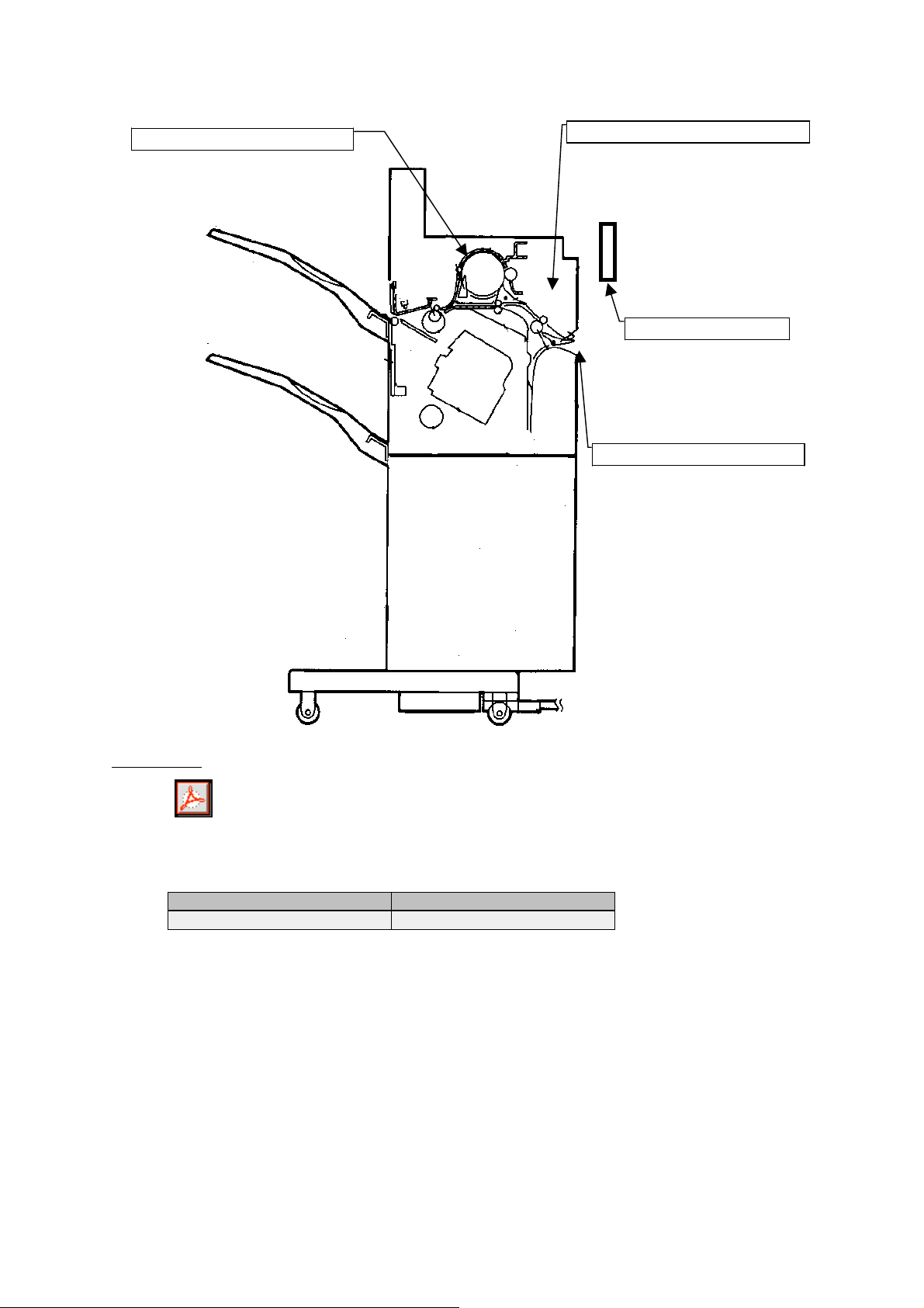
Transport drive unit
To rotate at a low, the unit of
the MJ-1005 is used.
Mid-pass drive unit
To rotate at a low,
* Gear train (arrange) change
* New motor use
Latch (accessory)
New
Entrance transport area
* To align the height of the
entrance in FC25P, the
entrance guide has been
changed.
* In order to improve the
transport function in relation
to short size paper, the
upper/lower roller width has
been expanded.
Attached File
MJ1014ServiceManual.pdf
Related Documents:
LinkTo: Link From:
Page 3
CHAPTER 1 GENERAL DESCRIPTION
II. SPECIFICATIONS
A. Specifications
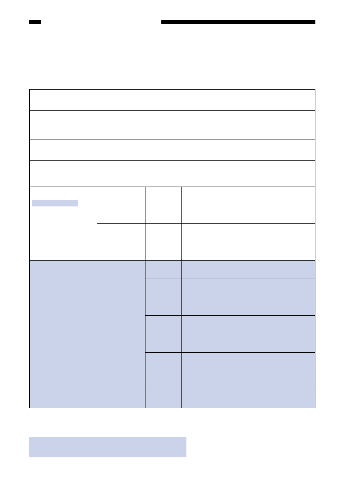
1. Finisher Unit
Item
Description
Stacking method
Stacking orientation
Stacking size
Paper weight
Bins
Modes
Stacking capacity
(MJ-1006/1007)
Stacking capacity
(MJ-1014)
Trays 1 through 2: by lifting tray
Face-up
AB: A3, A4, A4-R, A5-R, B4, B5, B5-R
Inch: LD, LG, LT, LT-R, ST-R
60 to 128 g/m
2
Trays 1 through 2
Non-sort: tray 1, 2
Sort: tray 1, 2
Staple: tray 1, 2
Non staple sort Small-size Tray 1: 147 mm high (1000 sheets)
(Note 1)
Tray 2: 147 mm high (1000 sheets)
(Note 2)
Large-size Tray 1: 74 mm high (500 sheets)
(Note 1)
Tray 2: 74 mm high (500 sheets)
Staple sort Small-size Tray 1: 110 mm high/30 sets (750 sheets)
(Note 1)
Tray 2: 110 mm high/30 sets (750 sheets)
Large-size Tray 1: 74 mm high/30 sets (500 sheets)
(Note 1)
Tray 2: 74 mm high/30 sets (500 sheets)
Non staple sort Small-size Tray 1: 147 mm high (850 sheets)
(Note 5)
Tray 2: 147 mm high (850 sheets)
Large-size Tray 1: 74 mm high (400 sheets)
(Note 5)
Tray 2: 74 mm high (400 sheets)
Staple sort Small-size Tray 1: 110 mm high/30 sets (750 sheets)
(Note 4)
Tray 2: 110 mm high/30 sets (750 sheets)
Large-size Tray 1: 74 mm high/30 sets (500 sheets)
(Note 4)
Tray 2: 74 mm high/30 sets (500 sheets)
Small-size Tray 1: 110 mm high/30 sets (600 sheets)
(Note 5)
Tray 2: 110 mm high/30 sets (600 sheets)
Large-size Tray 1: 74 mm high/30 sets (400 sheets)
(Note 5)
Tray 2: 74 mm high/30 sets (400 sheets)
Small-size Tray 1: 110 mm high/30 sets (550 sheets)
(Note 6)
Tray 2: 110 mm high/30 sets (550 sheets)
Large-size Tray 1: 74 mm high/30 sets (350 sheets)
(Note 6)
Notes:
1. Approximate when computed with reference to 80 g/m
2. Alignment may not be correct if 750 or more small-size sheets are stacked on tray 2.
3. The accuracy of the stack height is ±7 mm.
4. Approximate when computed with reference to 64~80 g/m
5. Approximate when computed with reference to 81~90 g/m
6. Approximate when computed with reference to 91~105 g/m
2
paper.
2
2
Tray 2: 74 mm high/30 sets (350 sheets)
paper.
paper.
2
paper.
Table 1-201
1-2
Page 4
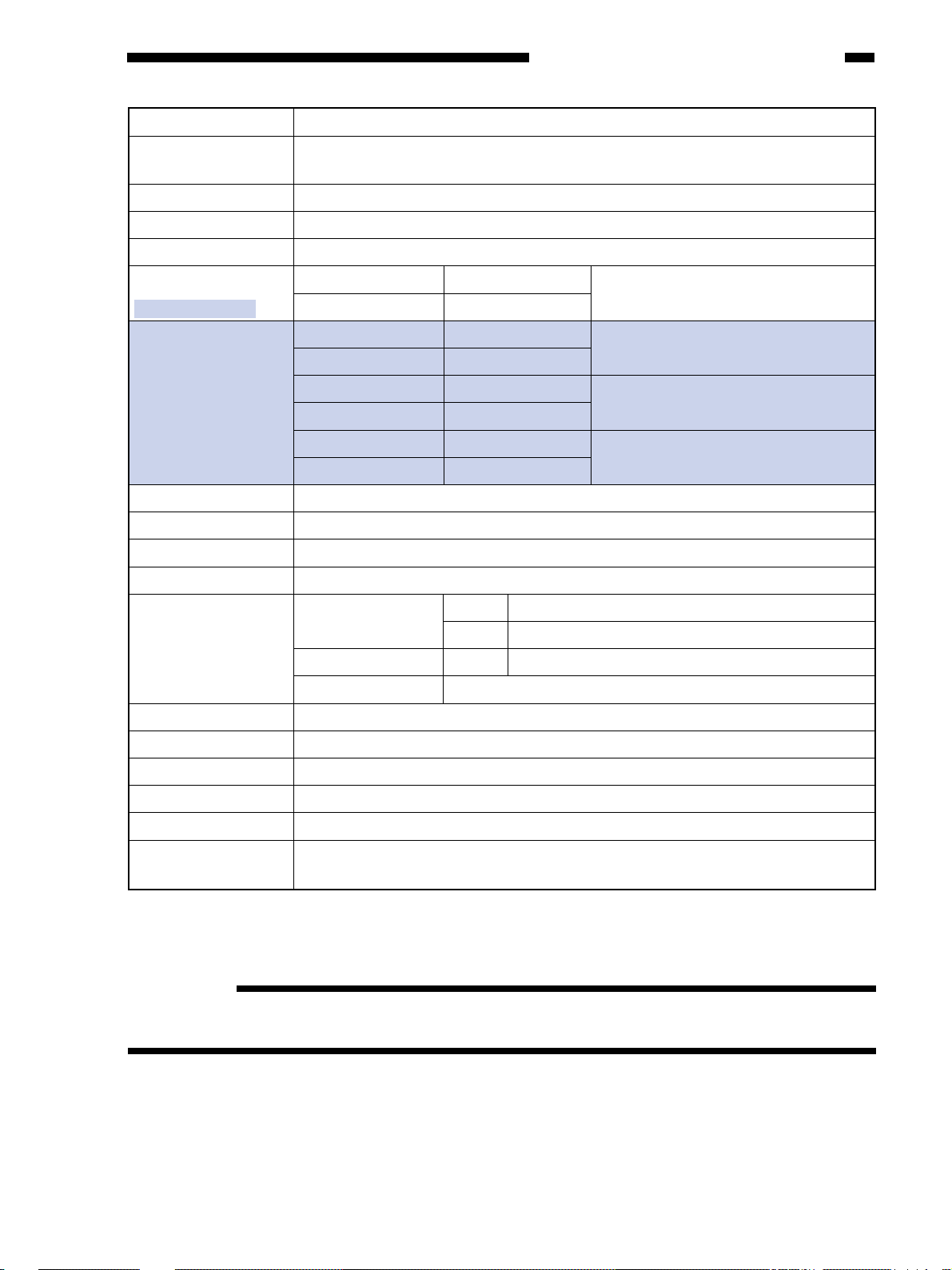
CHAPTER 1 GENERAL DESCRIPTION
Item
Size mixing
Stacking mixing
Stapling
Stapling position
Stapling capacity
(MJ-1006/1007)
Stapling capacity
(MJ-1014)
Staple supply
Staples
Staple detection
Manual stapling
Description
Size mixing: 74 mm or less
Stapling: 74 mm or less
Face-up
By rotating cam
See Figure 1-201.
Small-size 50 sheets
Large-size 30 sheets
Small-size 50 sheets
Large-size 30 sheets
Small-size 30 sheets
Large-size 15 sheets
Small-size 20 sheets
Large-size 10 sheets
Special staple cartridge (5000 staples)
Special
Provided
Not provided
Equivalent of 80 g/m2 paper
Equivalent of 64~80 g/m2 paper
Equivalent of 81~90 g/m2 paper
Equivalent of 91~105 g/m2 paper
Stapling size
Paper detection
Control panel
Dimensions
Weight
Power supply
Maximum power
consumption
1-point (diagonal) Front A3, B4, A4, A4-R, B5, LD, LG, LT, LT-R
Rear A3, B4, A4, B5, LD, LT
1-point Rear A4-R, LT-R, LG
2-point A3, B4, A4, B5, LD, LT
Tray 1, 2: provided
Not provided
716 × 603 × 1013mm (W × D × H)
MJ-1006: About 36kg, MJ-1007: About 56kg
From copier (24 VDC)
About 170 W (Average of the ordinary operation)
Table 1-202
Reference:
Small-size represents A4, B5, LT, while large-size represents A3, B4, A4-R, B5-R, LT-R, LD,
LG.
1-3
Page 5
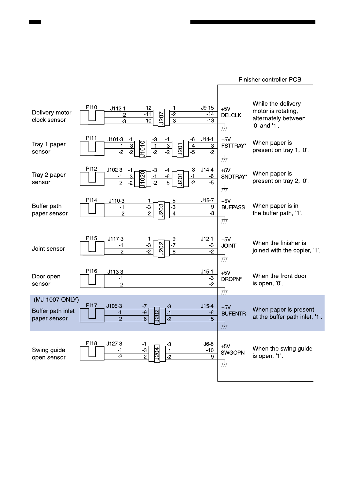
CHAPTER 2 FINISHER UNIT BASIC OPERATION
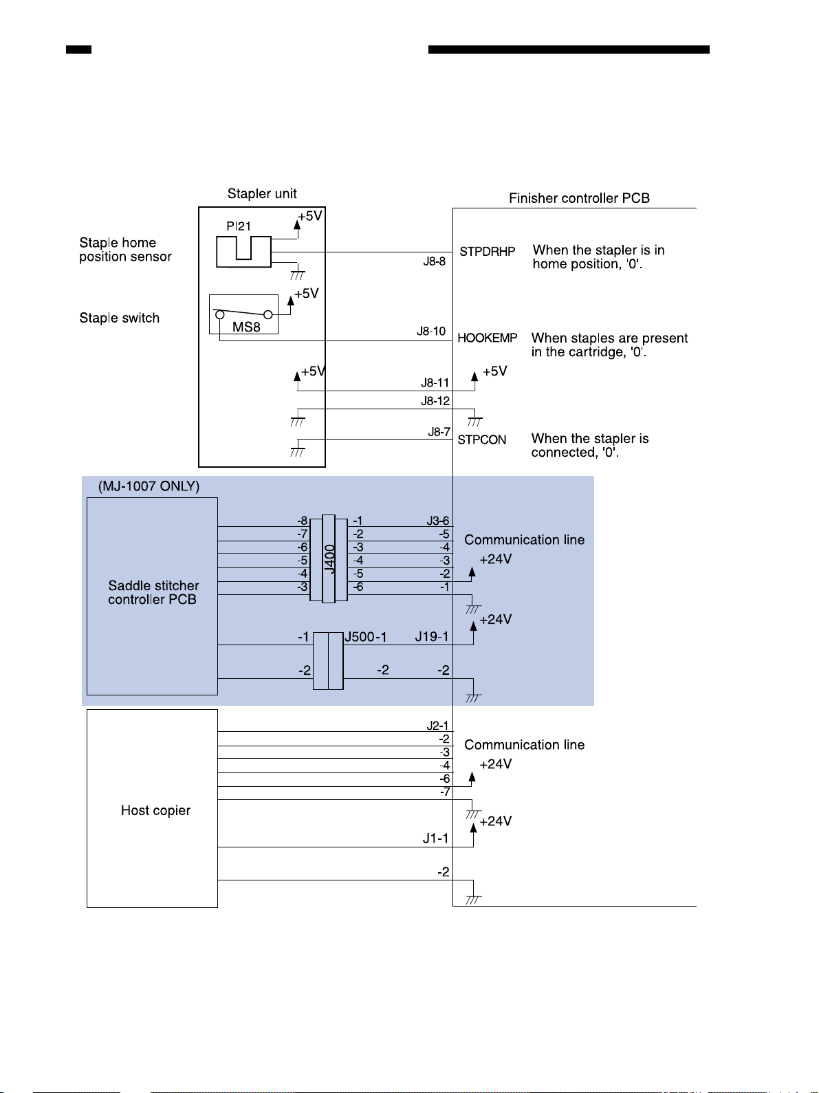
2. Inputs to the Finisher Controller PCB
2-4
Figure 2-104
Page 6
CHAPTER 2 FINISHER UNIT BASIC OPERATION
4. Inputs to and Outputs from the Finisher Controller PCB
2-6
Figure 2-106
Page 7
CHAPTER 2 FINISHER UNIT BASIC OPERATION
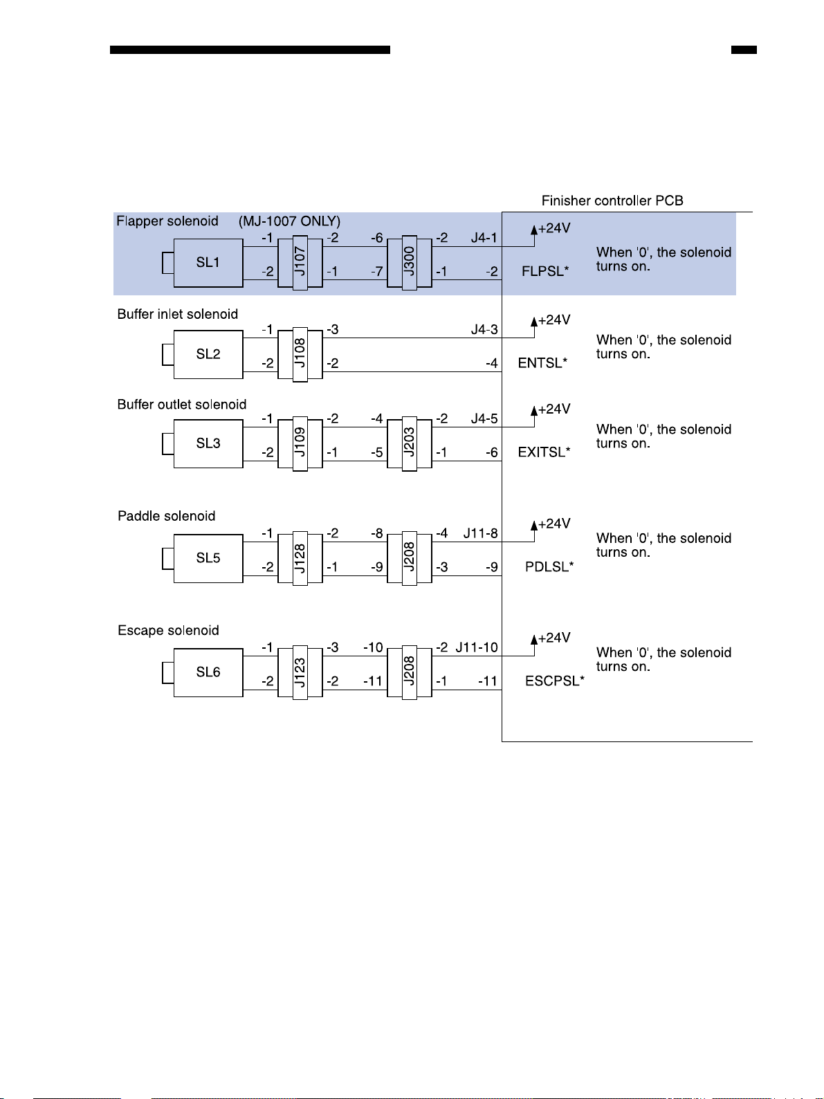
5. Outputs from the Finisher Controller PCB
Figure 2-107
2-7
Page 8
CHAPTER 2 FINISHER UNIT BASIC OPERATION
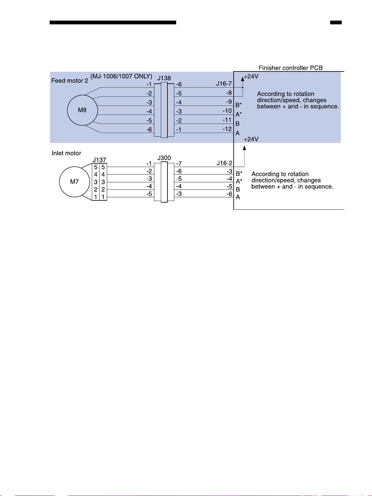
7. Outputs from the Finisher Controller PCB
Figure 2-109
2-9
Page 9

C. Feeding and Delivering
CHAPTER 2 FINISHER UNIT BASIC OPERATION
1. Outline
: MJ-1006/1007 ONLY
The finisher mov es copies arriving from the copier to the normal tray , or the saddle stitcher unit
(Saddle Finisher MJ-1007) according to the mode of delivery. On the trays, the copies are subjected
to job offset or stapling as instructed by the copier.
The inlet motor (M7), the feed motor (M1), and the feed motor (M8) are the stepping motors,
and the delivery motor (M2) is a DC motor. These motors are controlled by the microprocessor
(CPU) on the finisher controller PCB, and rotate either clockwise or counterclockwise.
The paper paths are equipped with the following five sensors for detection of paper (arrival,
passage):
●
Inlet sensor (PI1)
●
Delivery sensor (PI3)
●
Stapling tray sensor (PI4)
●
Buffer path paper sensor (PI14)
In addition, each delivery tray is equipped with a sensor designed to detect the presence/absence of paper on it.
●
No 1 tray paper sensor (PI11)
●
No. 2 tray paper sensor (PI12)
If a copy fails to reach or move past each sensor within a specific period of time, the finisher
controller PCB identifies the condition as a jam, and stops the ongoing operation and at the same
time informs the copier of the condition.
2-17
Page 10

CHAPTER 2 FINISHER UNIT BASIC OPERATION
2-18
Figure 2-216
Page 11

CHAPTER 2 FINISHER UNIT BASIC OPERATION
Figure 2-218
Figure 2-219
2-21
Page 12

CHAPTER 2 FINISHER UNIT BASIC OPERATION
Figure 2-233
2-31
Page 13

CHAPTER 2 FINISHER UNIT BASIC OPERATION
Figure 2-239
H. Detecting the Height of the Stack on the Tray
1. Outline
The number of sheets delivered to the tray and the number of sets (stapling or job of fset operations) are stored in memory by the finisher controller PCB. The height of the stack is check ed by the
height sensor (PS1). See Table 2-202 for the maximum loading capacity of each tray.
The finisher controller PCB stops operation when the conditions in Table 2-202 occur, informing the host copier that the tray is full.
Table 2-202
(MJ-1006/1007)
Stacking
Tray
Tray 1
Tray 2
Note: 1. The capacity for non-staple sort mode is approximate and computed based on 80 g/m2 paper.
2. Alignment for stacks consisting of 750 sheets or more is not guaranteed.
3. The accuracy of the stack height is ±7mm.
mode
Small-size
147 mm high
(1000 sheets)
147 mm high
(1000 sheets)
Non-staple sort Staple sort
Large-size
74 mm high
(500 sheets)
74 mm high
(500 sheets)
Small-size
750 sheets/30
sets, fewer of two
(or, 110 mm high)
750 sheets/30
sets, fewer of two
(or, 110 mm high)
Large-size
500 sheets/30
sets, fewer of two
(or, 110 mm high)
500 sheets/30
sets, fewer of two
(or, 110 mm high)
2-38
Page 14

(MJ-1014)
CHAPTER 2 FINISHER UNIT BASIC OPERATION
Tray
Tray 1
Tray 2
Stacking mode
Equivalent of
64~80 g/m
2
Equivalent of
~90 g/m
81
2
paper
Equivalent of
91~105 g/m
Equivalent of
64~80 g/m
2
Equivalent of
81~90 g/m
2
Equivalent of
91~105 g/m
paper
2
paper
paper
paper
2
paper
Small-size
--
147 mm high
(850 sheets)
--
--
147 mm high
(850 sheets)
--
Non-staple sort Staple sort
Large-size
--
74 mm high
(400 sheets)
--
--
74 mm high
(400 sheets)
--
Small-size
750 sheets/30 sets
(110 mm high)
600 sheets/30 sets
(110 mm high)
550 sheets/30 sets
(110 mm high)
750 sheets/30 sets
(110 mm high)
600 sheets/30 sets
(110 mm high)
550 sheets/30 sets
(110 mm high)
Note:
1. The term “small-size” stands for A4, LT, and B5.
2. The term “large-size” stands for A3, A4-R, B4, LG, LD and LT-R.
Large-size
500 sheets/30 sets
(74 mm high)
400 sheets/30 sets
(74 mm high)
350 sheets/30 sets
(74 mm high)
500 sheets/30 sets
(74 mm high)
400 sheets/30 sets
(74 mm high)
350 sheets/30 sets
(74 mm high)
Figure 2-240
2-39
Page 15

CHAPTER 2 FINISHER UNIT BASIC OPERATION
Figure 2-252
2-47
Page 16

CHAPTER 2 FINISHER UNIT BASIC OPERATION
4. Buffer Path Paper Sensor Stationary Jam
The sheet does not move past the buffer path paper sensor when an equivalent of twice the
feeding length of the sheet has been fed after the buffer pa th paper sensor turned on.
Figure 2-257
5. Delivery Sensor Delay Jam
a. Smaller than B5 or Non-standard Size Paper Path
The delivery sensor does not detect paper when an equi v alent of 260 mm has been fed after the
inlet sensor is turned on.
Figure 2-258
b. Standard Size Above B5 Paper Path and Buffer Path
The delivery sensor does not detect paper when an equi v alent of 460 mm has been fed after the
buffer path inlet pa per sensor is turned on.
Figure 2-259
: MJ-1006/1007 ONLY
2-50
Page 17

CHAPTER 2 FINISHER UNIT BASIC OPERATION
6. Delivery Sensor Stationary Jam
The sheet does not move past the delivery sensor when an equivalent of twice the feeding
length of the sheet has been fed after the delivery sensor turned on.
: MJ-1006/1007 ONLY
Figure 2-260
7. Stapling Tray Sensor Stationary Jam
a. With Stapling
The sheet does not move past the stapling tray sensor 1.6 sec after the delivery motor (M2)
turned on.
Figure 2-261
b. Without Stapling
The sheet does not move past the stapling tray sensor 2 sec after the deli very motor (M2) turned
on.
Figure 2-262
c. Job Offset
The sheet does not move past the stapling tray sensor 1 sec after the deli very motor (M2) turned
on.
8. Stapling Tray Sensor Delay Jam
No check is made for jams using the stapling tray sensor for either staple or job offset mode.
2-51
Page 18

CHAPTER 2 FINISHER UNIT BASIC OPERATION
III. POWER SUPPLY SYSTEM
1. Outline
The finisher controller PCB is supplied with 24 VDC power when the copier is turned on.
Some of the 24 VDC po wer is used to dri v e the motors and the solenoids etc., while the rest is used
for sensors and ICs on PCBs after being turned into 5 VDC by the w ork of the regulator IC (Q14) on
the finisher controller PCB. The 24 VDC po wer is also used to feed power from the f inisher controller PCB to the saddle stitcher controller PCB.
Some of the 24 VDC po wer used to dri ve motors is cut off when the door switch (MS1) is made
open. The power to the saddle stitcher controller PCB, however, will not be cut off.
Figure 2-301 is a block diagram showing the power supply system.
Figure 2-301
2. Protection Functions
The 24 VDC power channel used to drive motors and solenoids is equipped with a circuit
breaker (CB1) for protection against overcurrent. The 24 V channel used to drive the feed motor 1
(M1), feed motor 2 (M8), inlet pass motor (M7), alignment motor (M3), and stapler shift motor
(M4) is equipped with a fuse, which is designed to melt in the presence of overcurrent.
: MJ-1006/1007 ONLY
Caution:
Replace the lithium battery only with the one listed in the Parts Catalog. Use of different battery may
present a risk of fire or explosion. The battery may cause a fire or present chemical burn hazard if
mistreated. Do not recharge, disassemble, or dispose of it by fire.
Keep the battery out of reach of children and discard any used batteries promptly.
2-52
Page 19

CHAPTER 3
SADDLE STITCHER UNIT
BASIC OPERATION (MJ-1007)
I. BASIC OPERATION.................... 3-1
A. Outline .......................................3-1
B. Electrical Circuitry ......................3-2
C. Inputs to and Outputs
from the Saddle Stitcher
Controller PCB...........................3-3
II. FEEDING/DRIVE SYSTEM.........3-8
A. Outline .......................................3-8
III. PAPER DEPOSITING
MECHANISM.............................3-14
A. Outline .....................................3-14
B. Controlling the Inlet
Flappers...................................3-17
C. Controlling the Movement
of Sheets..................................3-21
D. Aligning the Sheets..................3-22
E. Controlling the Phase of
the Crescent Roller ..................3-25
IV. STITCHING SYSTEM ...............3-27
V. FOLDING/DELIVERY
SYSTEM....................................3-30
VI. CHECKING FOR A JAM ...........3-35
VII. POWER SUPPLY ......................3-39
Page 20

CHAPTER 4
MECHANICAL CONSTRUCTION
(A) FINISHER UNIT ..........................4-1
I. EXTERNALS AND
CONTROLS...............................4-1
A. External Covers ...................4-1
II. FEEDING SYSTEM ...................4-7
III. PCBs........................................4-13
(B) SADDLE STITCHER UNIT
(MJ-1007) ..................................4-14
Page 21

CHAPTER 5
MAINTENANCE AND INSPECTION
I. PERIODICALLY REPLACED
PARTS.........................................5-1
A. Finisher Unit...............................5-1
B. Saddle Stitcher Unit
(MJ-1007) ..................................5-1
II. CONSUMABLES AND
DURABLES .................................5-1
A. Finisher Unit...............................5-1
B. Saddle Stitcher Unit
(MJ-1007) ..................................5-1
III. PERIODICAL SERVICING ..........5-1
Page 22

CHAPTER 6
TROUBLESHOOTING
I. ADJUSTMENTS ..........................6-1
A. Electrical System
(finisher unit) ..............................6-1
B. Electrical System/MJ-1007
(saddle stitcher unit) ..................6-4
C. Mechanical System....................6-8
II. ARRANGEMENT OF
ELECTRICAL PARTS..................6-9
A. Finisher Unit...............................6-9
B. Saddle Stitcher Unit .................6-15
C. Var iable Resistors (VR),
Light-Emitting Diodes (LED),
and Check Pins by PCB ...........6-21
III. TROUBLESHOOTING...............6-23
A. Finisher Unit.............................6-23
B. Saddle Stitcher Unit
(MJ-1007) ................................6-31
Page 23

CHAPTER 6 TROUBLESHOOTING
3. Motors
6-12
Figure 6-203
Table 6-203
Page 24

4. Solenoids
CHAPTER 6 TROUBLESHOOTING
Figure 6-204
Table 6-204
6-13
Page 25

APPENDIX
A. Signal and Abbreviations............ A-1
B. Finisher Unit General Circuit
Diagram...................................... A-2
C. Finisher Unit Controller Circuit
Diagram...................................... A-3
D. Saddle Stitcher Unit General
Circuit Diagram (MJ-1007)........ A-11
E. Saddle Stitcher Unit Controller
Circuit Diagram (MJ-1007)........ A-12
F. Solvents and Oils...................... A-19
Page 26

B. Finisher Unit General Circuit Diagram
(MJ-1007)
(MJ-1006/1007)
(MJ-1007)
A-2
 Loading...