

Page 1

BSINo. G00I113 Page 1
BSI No.: G00I113
Publish
2000/09/29
Date:
Subject: FC-25P Service Manual
Model: FC25P
Category Field Application UNIT
New Model Description Others Documents
FactoryApplication: -
CONTENT
The new model (FC25P) is a product using the present model (FC15, FC22) as the base for the
printer.
This BSI is to substitute for a Service Manual by specifying the differences.
Elimination of optical system
z
Printer control only
z
[Differences]
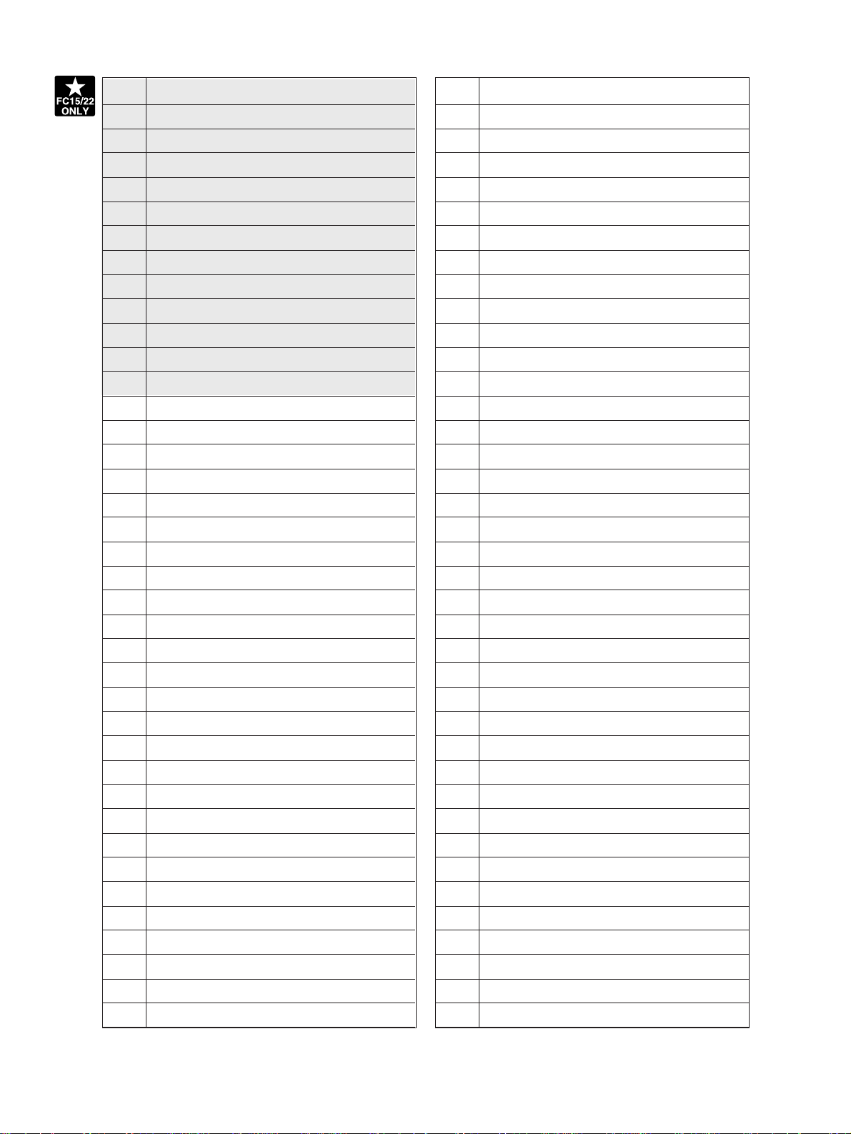
The following table clarifies the differences in the table of contents of the Service Manual of the FC15
and the FC22.
o : Parts common to the FC25P
#1 : A separate explanation for the FC25P is added.
#2 : There is no optical system so some part of the contents have become unnecessary for the
FC25P.
x : FC25P unnecessary parts --- Letters in italic
The pages indicated by the sign #1, #2, X are appended as a separate file.
[Service Manual]
Chapter Page Contents Remarks
1 1-1~1-6
2 2-1~2-31
3
3-1 Expression of Colors and 4-Step Copy Process
3-2~3-9 General Description of Copying Process ~
3-10 List of Copying Process Conditions
4
4-1~4-5
4-6~4-12
4-13
5 5-1~5-8
SPECIFICATIONS/ACCESSORIES/OPTIONS/
SUPPLIES
OUTLINE OF THE MACHINE
COPY PROCESS
Details of Copying Process
GENERAL OPERATION
Overview of Operation ~ Interruption copying
Detection of Abnormal Conditions ~
Immediately after the power is turned ON
Automatic paper feed copying
IMAGE PROCESSING
#1
#2
o
#2
o
#2
o
#2
o
Page 2

BSINo. G00I113 Page 2
6 6-1~6-4
7 7-1~7-6
8 DISPLAY UNIT
8-1~8-6
8-7~8-10
9 9-1~9-32
10 10-1~10-10
11 11-1~11-16
12 12-1~12-22
13 13-1~13-30
14 14-1~14-10
15 15-1~15-8
16 16-1~16-16
17 17-1~17-6
18 18-1~18-2
18-3
18-4~18-7
IMAGE QUALITY CONTROL
COLOR REGISTRATION CONTROL
Detailed Drawing of the Control Panel and the
Display Panel ~ Relation between Copier
Conditions and Operator's Actions
Description of Operation ~ Disassembly and
Replacement
SCANNER
LASER OPTICAL UNIT
DRIVE SYSTEM
PAPER FEEDING SYSTEM
PROCESSING UNIT (EPU)
UNITS AROUND THE PROCESSING UNIT
TRANSFER/TRANSPORT UNIT
FUSER UNIT
POWER SUPPLY UNIT
PWA-F-SIC-310~PWA-F-LGC-310
PWA-F-IMC-310
PWA-F-SCM-310~PWA-F-MAC-511
o
o
#1
o
x
o
o
o
o
o
o
o
o
o
#1
o
[Service Handbook
Chapter
1
2
Page Contents Remarks
1-1~1-4
1-5~1-18
1-19~1-42
1-43
1-45
1-46~1-50
1-51~1-52
1-53~1-57
1-58~1-73
1-74~1-76
1-77~1-82
1-83
1-84
]
ADJUSTMENT ITEMS
Error Code List
Self Diagnostic mode ~ Output
check (03
Test print mode(04) ~ Setting
mode(08)
Registering/changing ID codes
Adjustment Order (Copy Image
Related Adjustment)
Automatic Adjustment of the
Auto-Toner Circuit ~ Automatic
Initialization of Image Quality
Control
Copy lmage Dimensional
Adjustment
Paper alignment (paper buckle) at
the main registration roller ~
Printer related adjustment
Scanner related adjustment ~
Sharpness Adjustment
High-Voltage Transformer Setting
~ Adjusting Doctor-to-Sleeve Gap
Adjusting the Scanner Section
Adjusting the Cassette for
Sidewise Deviation
Key Copy Counter (MU-8, MU-10)
PREVENTIVE MAINTENANCE
(PM)
#1
o
#2
x
#2
o
#2
o
x
o
x
o
x
Page 3

BSINo. G00I113 Page 3
2-1~2-11
2-12
2-13
3 3-1~3-4
4
4-1~4-9
4-10~4-11
4-12~4-22
4-23~4-24
4-25~4-34
4-33~4-35
4-36
4-37~4-39
4-40~4-45
4-45~4-51
4-52
4-53~4-80
5 5-1~5-28
6
6-1
6-2
Types of Preventive Maintenance
~ Peventive Maintenance
Checklist
PM Kit
List of Adjustment Tools
PRECAUTIONS FOR STORING
& HANDLING SUPPLIES
TROUBLESHOOTING
Troubleshooting Based on Error
Code ~ Paper jam in ADU and
reversing area
Original jam in the RADF
Paper jam in the sorter ~ Paper
feeding system related service
call
Scanner related service call
Copy process related service call
~ Fuser unit related service call
Communications related service
call
ADF related service call
Other service calls ~ Laser optical
unit related service call
Sorter related service call
Image quality related service call
Options related service call
Image processing options related
service call ~ Troubleshooting of
Image
FIRMWARE UPDATING
WIRE HARNESS CONNECTION
DIAGRAMS
AC Wire Harness
DC Wire Harness Appendix
o
#1
o
o
o
x
o
x
o
#2
x
o
#2
o
#2
o
o
o
o
Attached File
G00I113(Manual).pdf G00I113(Handbook).pdf
Related Documents:
LinkTo: Link From:
Page 4

• Print speed (For FC-25P) (Prints/min.)
Paper supply
Paper size
A3, LD
B4, LG
A4-R, B5-R, LT-R
A4, LT
B5
A5-R, ST-R
A3 WIDE
Thick Paper 1(Full size)
Thick Papaer 2/3(Full size)
OHP Sheet (A4, LT)
Color modes/Monochrome modes
Cassette
12
14
17
25
Same as normal papers
4
LCF
–
25
–
–
–
SFB
12
14
17
20
12
2~6
4
January 2000 © TOSHIBA TEC 1 - 1 - 2 FC-22 SPECIFICATIONS
Page 5

System copy speed
*
FC-15 FC-22
Copy mode
Number of
sheets set
Color modes
Monochrome
modes
The same speed in both color
and monochrome modes
Copies/min.Copies/min. Copies/min.
Single-sided originals 1 set 12 16 16
x 3 sets 14 19 19
Single-sided copies 5 sets 14 20 20
Single-sided originals 1 set 4 4 4
x 3 sets 8 9 9
Two-sided copies 5 sets 10 12 12
Two-sided originals 1 set 4 4 4
x 3 sets 8 9 9
Two-sided copies 5 sets 10 12 12
Two-sided originals 1 set 11 12 12
x 3 sets 13 17 17
Single-sided copies 5 sets 14 19 19
Any of the left copy speeds includes the first cop y time and is a v ailable when the corresponding copy
*
mode is used and 10 A4-sized originals are set in the automatic document feeder.
These values are attained in full color mode copying.
*
• Paper
Cassette Duplex copy LCF Bypass copy Remarks
Size A3~A5R A4, LT A3~A5-R Irregular or
LD~ST-R LD~ST-R arbitrary sizes can be set.
Weight 64~105g/m2, 17~28 lb. 64~209g/m
17~110 lb. index
Special paper – – – Recommended
OHP film
2
• First print time ................... Approx. 10.3 seconds or under (A4/LT, the first cassette, 100%)
• Warming-up time............... Approx. 9 minutes
• Multiple copying ................ Up to 999 copies;entry by digital keys
• Reproduction ratio.............Actual ratio: 100±0.5%
Zooming: 25~400% in increments of 1%
• Resolution/Gradation Read: 600 dpi/256 gradation
Write: Corresponding to 9600 dpi x 600 dpi
(primary scanning only : 16 division smoothing)
• Excluded image width Leading edge: 5.0±2.0 mm, Trailing edge: 2.5±2.0 mm
Side edge: 2.0±2.0 mm
• Paper feeding.................... Automatic feeding: Copier’s cassettes–2 pieces standard (expandable up
to 4 pieces by installing optional cassettes)
LCF–Optional (Stack height 165 mm : Equivalent to 1500
sheets of 80 g/m2, 20 lb.)
Bypass feeding:
• Capacity for originals .......................................A4, A4-R, B5, B5-R, A5-R, LT, LT-R, ST-R:
(Stack height 8 mm : Equivalent to 50 sheets of 80 g/m2, 20 lb.)
50 sheets
(Optional automatic document feeder) B4, Folio, LG, Comp: 35 sheets
A3, LD: 25 sheets
FC-22 SPECIFICATIONS 1 - 2 January 2000 © TOSHIBA TEC
Page 6

• Stacking capacity of sheets ... Paper weight 64~80 g/m2, 17~22 lb.: 50 sheets
(Optional automatic duplexing unit)
• Toner supplying...................... Automatic toner-density detection and supply
• Density control ....................... Automatic density mode and manual density mode selectable in 11 steps
• Weight....................................
Paper weight 81~90 g/m2, 23~24 lb.: 40 sheets
Toner cartridge replacing method
Approx. 200 kg (FC15/22)
, Approx. 190kg (FC25P)
• Power requirements...............
• Power consumption................
The automatic document feeder, automatic duplexing unit and LCF are supplied with electric
*
power through the copier.
• Total counter........................... Mechanical counter (7 digit)
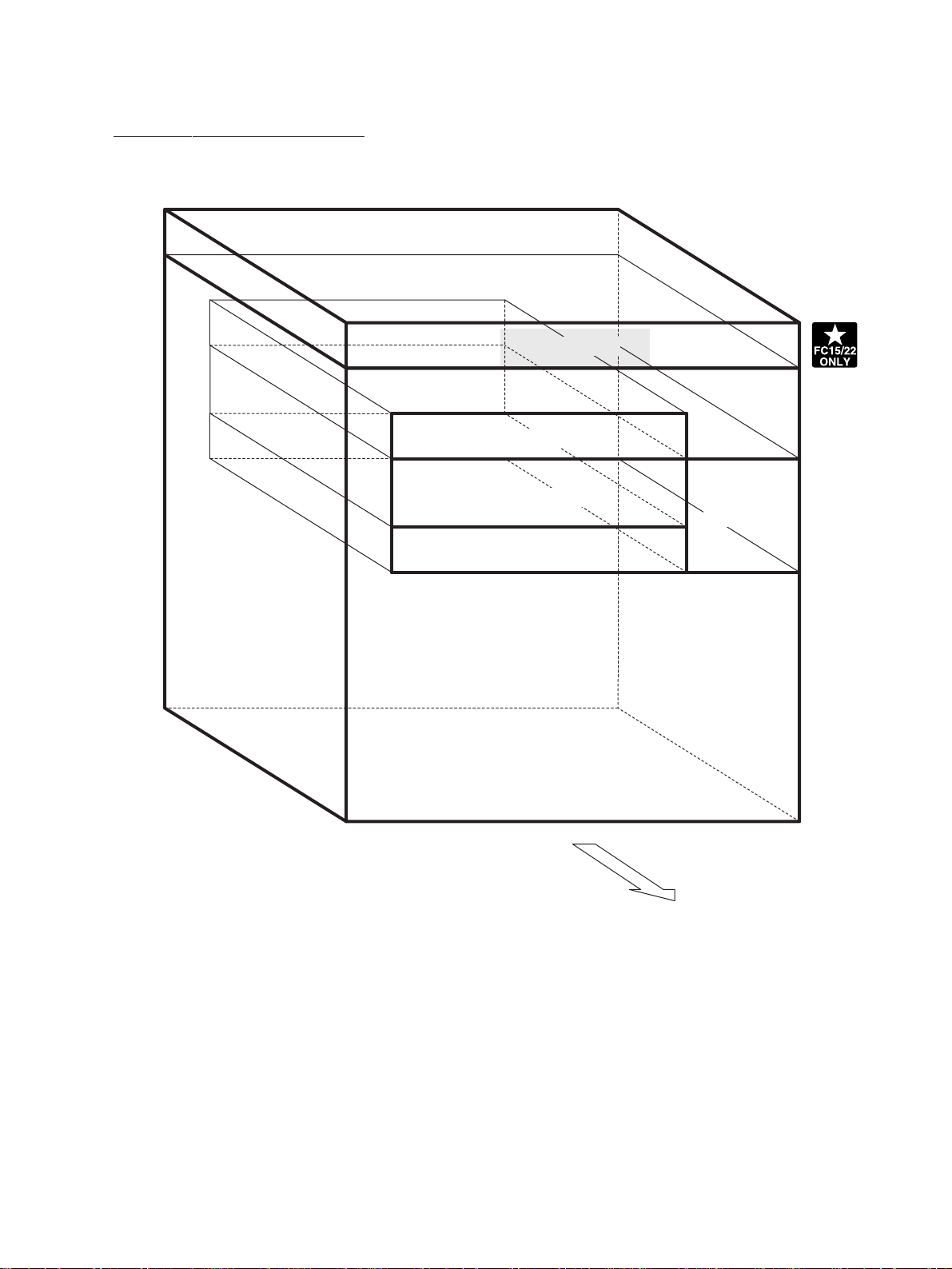
• Dimensions ............................ See the figure below (W845 x D750 x H1000 mm)
AC 115V/16A, AC 220 – 240V/9A (FC15/22)
9A (FC25P)
2.0 kW or less (115V series, 200V series) (FC15/22)
20kw or less, (200V series) (FC25P)
, AC115V/12A, AC220-240V/
, 1.5kw or less (115V)
1000 mm
750 mm
845 mm
January 2000 © TOSHIBA TEC 1 - 3 FC-22 SPECIFICATIONS
Page 7

1.2 Accessories
Setup instructions 1 pc.
Operator’s manual 1 pc. (not available for MJD)
Color copy guide 1 pc. (not available for MJD)
Setup report 1 set. (for NAD and MJD)
CS card 1 pc. (for MJD)
Operator’s manual pocket 1 pc.
Detouchable code
Copy receiving tray 1 pc.
Warrantee sheet 1 pc. (for NAD)
DF level up kit 1 pc.
Cassette size plate for OHP film 1 pc.
Media Pack 1 pc.
Manual for Visual Cal 1 pc.
1 pc. (for ASD, AUD and MJD)(FC15/22)
/ 1 pc. (FC25P)
* Machine version
NAD: North America
MJD: Europe
AUD: Australia (FC15/22)/ Australia, South America (FC25P)
ASD: Asia
FC-22 SPECIFICATIONS 1 - 4 January 2000 © TOSHIBA TEC
Page 8

1.3 Options
Platen cover KA-2060PC
Automatic document feeder (RADF) MR-3006A, MR-3006E
Automatic duplexing unit (ADU) MD-5007, MD-5007N
Cassette module MY-1011, MY-1011N
Slot cover KE-FC22
Large capacity feeder (LCF) MP-1501
LCF kit KN-FC22L01
20-bin staple sorter MG-2014
Installation kit for staple sorter KN-FC22S01
Staple cartridge
External printer controller (Fiery Z4) KR-7037
Built-in printer controller (Fiery X4e) KR-7038
Video I/F kit for external controller connection KR-8005
Control panel kit for built-in controller KR-8006
Key copy counter MU-8, MU-10
Work table KK-2460
Work table kit KN-FC22W01
AI board KR-2030
Damp heater kit MF-FC22U, MF-FC22E
Operator’s manual
(English, French, German, Spanish, Italian) MANUAL FC25P (FC25P)
Color copy guide GUIDE FC22
(English, French, German, Spanish, Italian)
Fninisher MJ1014
STAPLE-400 (FC15/22)
STAPLE-700 (FC25P)
MNL2-FC22 (FC25/22)
January 2000 © TOSHIBA TEC 1 - 5 FC-22 SPECIFICATIONS
Page 9

1.5 System List
feeder
MP-1501
Large capacity
KR-7037
(Fiery Z4)
KR-8005
KK-2460
Work table
KA-2060PC
Platen cover
MR-3006A, MR-3006E
Automatic document feeder
Key copy counter
Work table kit
KN-FC22W01
MU-8, MU-10
Cassette module
MY -1011, MY-1011N
KN-FC22L01
LCF kit
Cassette (Standard)
Cassette (Standard)
controller connection
External printer controller
Video I/F kit for external
MD-5007, MD-5007N
Automatic duplexing unit
KE-FC22
Slot cover
KN-FC22S01
staple sorter
KR-8006
built-in controller
Control panel kit for
Installation kit for
MG-2014
20-bin staple sorter
AI board
KR-2030
Finisher
KR-7038
Built-in printer
STAPLE-400
Staple cartridge
STAPLE-700
Staple cartridge
MJ-1040
controller (Fiery X4e)
FC-22 SPECIFICATIONS 1 - 6 January 2000 © TOSHIBA TEC
Page 10

2. OUTLINE OF THE MACHINE
124
90
89
72
95
125
122
116
110
104
106
121
117
118
107
105
108
120
119
103
109
113
13
4
114
115
123
111
112
69
67
64
43 59 35 54 58
22
53 57
10
52 56 32 28
21 60 16 20
14
55 19
63
12
27 62 34 26 61 33 25 40
11
24
65 66
70
68
51 77 3146 38 49 75 29 44 36
73
15
85
87
91
93
102
102
102
101
84
82
86
88
92
101
101
101
102
83
80 81
7178
47 39 50 76 30 45 37 48 74
3 215
8 7
23 42 18941 17
6
126, 127
79
94
2.1 Sectional View
[A] Front view (The drive system is illustrated in [B] and [C])
January 2000 © TOSHIBA TEC 2 - 1 FC-22 OUTLINE OF THE MACHINE
Page 11
1 Carriage 1
40 Cleaning blade Y
2 Exposure lamp
3 Reflector
4 Mirror 1
5 Thermostat
6 Carriage 2
7 Mirror 2
8 Mirror 3
9 Lens
10 CCD PC board
11 Scanner control board
12 Original glass
13 Carriage fan
14 SCM fan
15 SIC fan
16 Drum Y
17 Drum M
18 Drum C
19 Drum K
41 Cleaning blade M
42 Cleaning blade C
43 Cleaning blade K
44 Recovery blade Y
45 Recovery blade M
46 Recovery blade C
47 Recovery blade K
48 Toner recovery auger Y
49 Toner recovery auger M
50 Toner recovery auger C
51 Toner recovery auger K
52 Discharge LED Y
53 Discharge LED M
54 Discharge LED C
55 Discharge LED K
56 Main charger Y
57 Main charger M
58 Main charger C
20 Developer sleeve (Magnetic roller) Y
21 Developer sleeve (Magnetic roller) M
22 Developer sleeve (Magnetic roller) C
23 Developer sleeve (Magnetic roller) K
24 Upper mixer Y
25 Upper mixer M
26 Upper mixer C
27 Upper mixer K
28 Lower mixer Y
29 Lower mixer M
30 Lower mixer C
31 Lower mixer K
32 Doctor blade Y
33 Doctor blade M
34 Doctor blade C
35 Doctor blade K
36 Scattered toner recovery roller Y
37 Scattered toner recovery roller M
59 Main charger K
60 Charger wire cleaner Y
61 Charger wire cleaner M
62 Charger wire cleaner C
63 Charger wire cleaner K
64 Image quality sensor
65 Color registration sensor
66 Transfer belt
67 Transfer belt drive roller
68 Transfer belt cleaning blade
69 Transfer belt recovery blade
70 Transfer belt toner recovery auger
71 Suction charger
72 Transfer belt contact/release motor
73 Transfer belt driven roller
74 Transfer roller Y
75 Transfer roller M
76 Transfer roller C
38 Scattered toner recovery roller C
39 Scattered toner recovery roller K
FC-22 OUTLINE OF THE MACHINE 2 - 2 January 2000 © TOSHIBA
77 Transfer roller K
78 Transfer belt push-up mechanism
Page 12

[C] Rear drive system
4213 49 5
26
25
24
36
27,28
36
30,31
36
23
22
10
11
21
14 15 7 16 17
6 9 18 208
29
32
50
13
12
48
37
19 3839
45
47
40
42
41
43
46
4446 46
36
January 2000 © TOSHIBA TEC 2 - 5 FC-22 OUTLINE OF THE MACHINE
Page 13

1 Scan motor
2 Drive belt
3 Drive pulley
4 Driven pulley
5 Carriage drive wire
6 Drum motor Y (drum Y)
7 Drum motor M (drum M)
8 Drum motor C (drum C)
9 Drum motor K (drum K)
10 Color developer motor
11 Color developer drive belt
12 Black developer motor
13 Black developer drive belt
14 Developer sleeve (magnetic roller) Y
15 Developer sleeve (magnetic roller) M
16 Developer sleeve (magnetic roller) C
17 Developer sleeve (magnetic roller) K
18 Used toner transport unit (EPU side)
drive belt
42 Paper exit gate solenoid
43 ADU transport roller 1
44 ADU transport roller 2
45 ADU transport roller 3
46 ADU transport drive belt
47 Used toner transport motor
48 Used toner transport unit (main unit
side) drive belt
49 Document motor
50 Developer removal shutter open/close
motor
19 Transfer belt motor
20 Transfer belt drive roller
21 Registration roller
22 Registration clutch
23 Paper feed motor
24 Feed path clutch
25 Bypass feed roller
26 Bypass feed clutch
27 1st cassette feed roller
28 1st cassette feed clutch
29 1st cassette tray-up motor unit
30 2nd cassette feed roller
31 2nd cassette feed clutch
32 2nd cassette tray-up motor unit
36 Transport roller
37 Fuser motor
38 Upper fuser roller
39 Upper cleaning roller
40 Fuser exit roller
41 Exit roller
FC-22 OUTLINE OF THE MACHINE 2 - 6 January 2000 © TOSHIBA
Page 14
2.2 Location of Electrical Parts
[A] Arrangement of Various Units
Scanner unit
Laser optical unit
Processing unit
Fuser unit
Transfer/transport unit
Main unit
Rear side
January 2000 © TOSHIBA TEC 2 - 7 FC-22 OUTLINE OF THE MACHINE
Page 15

2
[B] Scanner unit
(B-1) Motors
(B-2) Sensors and switches
[A4 series]
M4
M1
APS-1, 2, 3
APS-R APS-C
M3
M
Rear side
SEN1SEN2
Rear side
[LT series]
APS-C
APS-R
APS-1
APS-3
SEN1SEN2
Rear side
FC-22 OUTLINE OF THE MACHINE 2 - 8 January 2000 © TOSHIBA
Page 16

(B-3) PC boards
SCM
CCD
FUS-SCN
DH1-1 DH1-2
SDV
Rear side
(B-4) Others
THM02
EXP
Rear side
LRG
January 2000 © TOSHIBA TEC 2 - 9 FC-22 OUTLINE OF THE MACHINE
Page 17

SSR-L
R
SSR-U
NFL
BR
PS
PWC
INL
(G-4) PC boards
SIC
IMC
Control panel
KEY DSP PNL
MTH
HVT-M-Y
HVT-M-M
HVT-M-C
HVT-M-K
(G-5) Others
LGC
Rear side
January 2000 © TOSHIBA TEC 2 - 15 FC-22 OUTLINE OF THE MACHINE
Rear side
Page 18

2.3 Symbols and Functions of Various Devices
(1) Motors
Symbol
M1 SCN-MOT (B-1)
Name Function Remarks
Scans the carriages.
Scan motor
M2 DCM-MOT (B-1)
Drives the original-width indicator.
Document motor
M3 CRG-FAN (Fan, 80 square) (B-1)
Carriage fan motors
M4 SCM-FAN (Fan, 60 square) (B-1)
Cool the surroundings of the carriages.
(2 pcs.)
Cools SCM PC boards.
SCM fan motor
M5 IN-FAN (Fan, 60 square) (G-1)
SIC fan motor
M6 OUT-FAN (Fan, 60 square) (G-1)
SIC fan motor
M7 PU-FAN (Fan, 80 square) (G-1)
Ozone exhaust fan motor
M8 EX-FAN (Fan, 80 square) (G-1)
Fuser-unit exhaust fan motor
M9 POW-FAN (Fan, 80 mm square) (G-1)
Cools the SIC PC boards (suction).
Cools the SIC PC boards (exhaust).
Exhausts the ozone of copier.
Cools the fuser unit.
Cools the power unit.
Power-unit fan motor
M10 USTN-MOT (G-1)
Used toner transport motor
M11 POL-MOT (C-1)
Polygonal motor
M12 Y-TILT-MOT (C-1)
Tilt motor Y
M13 M-TILT-MOT (C-1)
Tilt motor M
M14 C-TILT-MOT (C-1)
Tilt motor C
M15 Y-TNR-MOT (G-1)
Toner motor Y
M16 M-TNR-MOT (G-1)
Toner motor M
M17 C-TNR-MOT (G-1)
Toner motor C
M18 K-TNR-MOT (G-1)
Transports used toner to the toner bag.
Drives the polygonal mirror.
Drives the parallel adjustment controls
of the laser optical system (Y).
Drives the parallel adjustment controls
of the laser optical system (M).
Drives the parallel adjustment controls
of the laser optical system (C).
Supplies toner (Y).
Supplies toner (M).
Supplies toner (C).
Supplies toner (K).
Toner motor K
FC-22 OUTLINE OF THE MACHINE 2 - 16 January 2000 © TOSHIBA
Page 19

(5) Sensors and thermistors
Symbol Name Function Remarks
APS-1,2,3
APS-1, 2, 3 (3-beam) (B-2)
APS-C APS-C
Detects the size of original documents.
(A4 series)
APS-R APS-R
Automatic original detection sensor
APS-1 APS-1 (B-2)
APS-3 APS-3
Detects the size of original documents.
(LT series)
APS-C APS-C
APS-R APS-R
Automatic original detection sensor
CCD CCD-SEN (B-3)
Reads out information on originals.
CCD sensor
SEN1 HP-SEN (B-2)
Detects the carriage home position.
Carriage home position sensor
SEN2 PLTEN-SEN (B-2)
Platen sensor
SEN3-1 CSPEN-SEN (for 1st cassette) (G-3)
SEN3-2 CSPEN-SEN (for 2nd cassette)
Cassette paper-empty sensor
SEN4 MNPEN-SEN (G-3)
Bypass paper sensor
Detects if the platen cover is open or
closed.
Detects if there is paper in the cassette
or not.
Detects if there is paper in the bypass
tray or not.
SEN5-1 CSLIM-SEN (for 1st cassette) (G-3)
SEN5-2 CSLIM-SEN (for 2nd cassette)
Cassette tray-up limit sensor
SEN6-1 CSJAM-SEN (for 1st cassette) (G-3)
SEN6-2 CSJAM-SEN (for 2nd cassette)
SEN6-3 CSJAM-SEN (for 3rd cassette)
SEN6-4 CSJAM-SEN (for 4th cassette)
Cassette-feed jam sensor
SEN7 OHPE-SEN (G-3)
OHP edge sensor
SEN8 OHPC-SEN (G-3)
OHP center sensor
SEN9 PWA-F-SFB (G-3)
Bypass paper-width sensor
SEN10 RGST-SEN (G-3)
Registration sensor
Detects paper inside the cassette as
well as detecting if the cassette tray is
at its upper limit.
Detects paper misfeeding.
Detects if paper or OHP is set.
Detects if paper or OHP is set.
Detects the paper width of the bypass
tray.
Detects if paper has reached the registration roller or not.
FC-22 OUTLINE OF THE MACHINE 2 - 20 January 2000 © TOSHIBA
Page 20

(6) Heaters and lamps
Symbol Name Function Remarks
EXP EXPO-LAMP (B-4)
Exposes the original.
Exposure lamp
LRG PS-LRG-310 (B-4)
Controls the exposure lamp.
Lamp regulator
DH1-1 DNP-HTR (for lenses) (B-3)
DH1-2 DNP-HTR (for mirrors)
Prevents condensation in the scanner
section.
Damp heater
DH3-1 DNP-HTR (paper feed side) (E-1)
DH3-2 DNP-HTR (paper exit side)
Prevents condensation on the drum surface.
Damp heater
LAMP1 UP-LAMP [F]
Heats the upper fuser roller.
Upper fuser lamp
LAMP2 LOW-LAMP [F]
Heats the lower fuser roller.
Lower fuser lamp
ERS-Y ERAS-LED (Y) (D-2)
ERS-M ERAS-LED (M)
Removes residual charge on the drum
surface.
ERS-C ERAS-LED (C)
ERS-K ERAS-LED (K)
Discharge LED lamp
FC-22 OUTLINE OF THE MACHINE 2 - 22 January 2000 © TOSHIBA
Page 21

(7) PC boards
Symbol Name Function Remarks
SIC PWA-F-SIC-310 (G-4)
SIC PC board
LDR-Y PWA-F-LDR-310 (Y) (C-2)
Controls image processing and the
control panel.
Drives the lasers.
LDR-M PWA-F-LDR-310 (M)
LDR-C PWA-F-LDR-310 (C)
LDR-K PWA-F-LDR-310 (K)
Laser drive PC board (LDR board)
OPT PWA-F-OPT-310 (C-2)
Detects the position of laser beams.
H-Sync signal detection PC board
MTH PWA-F-MTH-310 (G-4)
Relays between SIC and IMC.
Mother board
LGC PWA-F-LGC-310 (G-4)
General control of the copier.
LGC PC board
IMC
RLY PWA-F-RLY-310 (C-2)
PWA-F-IMC-310 (FC15/22)
PWA-F-IMC-313 (FP25P)
IMC PC board
Laser relay PC board (RLY board)
Controls image processing and color
registration.
Relays between IMC and laser drive PC
boards.
Controls the scanner section.
(G-4)
SCM PWA-F-SCM-310 (B-3)
Scanner control PC board (SCM board)
CCD PWA-F-CCD-310 (B-3)
CCD PC board
Controls the pre-processing of CCD
image data.
Controls the scan motor.
SDV PWA-F-SDV-230 (B-3)
Scan motor drive PC board
DSP PWA-F-DSP-310 (G-4)
PNL PWA-F-PNL-310
DSP PC board
PNL PC board
KEY PC board
KEY PWA-F-KEY-310
Control panel PC board
January 2000 © TOSHIBA TEC 2 - 23 FC-22 OUTLINE OF THE MACHINE
Page 22

(8) Transformers
Symbol Name Function Remarks
HVT-M-Y
HVT-M-M
HVT-M-C
HVT-M-K
PS-HVT-M-310 (Y) (G-4)
PS-HVT-M-310 (M)
Produces high voltages for charging,
development and discharging.
PS-HVT-M-310 (C)
PS-HVT-M-310 (K)
Main high-voltage transformer
HVT-TB
PS-HVT-TB-310 (E-2)
Transfer transformer
Produces high voltages for tr ansfer and
suction.
(9) Others
Symbol Name Function Remarks
SSR-U SSR (U) (G-5)
SSR-L SSR (L)
Switches the upper and lower fuser
lamps ON and OFF.
Solid-state relay
FUS-SCN
FUS-TBU
PWA-F-FUS-351 (SCN) (B-3)
PWA-F-FUS-351 (TBU) (E-2)
Fuse PC board
PS PS-ACC-310JU (115V series) (G-5)
Prevents over-current to damp heaters
(scanner section, transfer/transport
unit).
Provides electrical power.
PS-ACC-310E (200V series)
Switching power supply
NFL FL-VU-220F (115V series) (G-5)
Cuts off noise.
FILTER-ZSB2210 (200V series)
Noise filter
BR B-NK1D-110-20A (115v series) (G-5)
Safety switch
B-NRW10-10A-Y (200V series)
Breaker
INL INLET-AP300-2A2 (200V series) (G-5)
Inlet
Inlet
PWC CBL/P-152UC-1 (115V series) (G-5)
Power cable
CBL/P-INLET-EUR (200V series)
Power cable
R K-LOAD-313 24V dummy load (G-5)
Dummy Load Do not touch as it becomes high
temperature
FC-22 OUTLINE OF THE MACHINE 2 - 24 January 2000 © TOSHIBA
Page 23

[I] Exit-side upper cover
(1) Shift the slide cover toward the rear to remove
it.
(2) Unscrew 3 screws and remove the exit-side
upper cover.
[J] Exit-side lower cover, front cover and rear
cover, and paper-exit unit cover
(1) Remove the exit-side lower cover (4 screws).
(2) Remove the exit-side front cover (2 screws).
(3) Remove the exit-side rear cover (2 screws).
(4) Remove the paper-exit unit cover (6 screws).
[K] Right top cover
(1) Remove the right top cover (3 screws).
Exit-side upper cover
Slide cover
Exit-side
rear
cover
Left top cover
Center top cover
Exit-side
front cover
Paperexit unit
cover
Exit-side
lower cover
Right top cover
[L] Center top cover
(1) Remove the center top cover (3 screws).
[M] Left top cover
(1) Remove the left top cover (3 screws).
January 2000 © TOSHIBA TEC 2 - 29 FC-22 OUTLINE OF THE MACHINE
Page 24
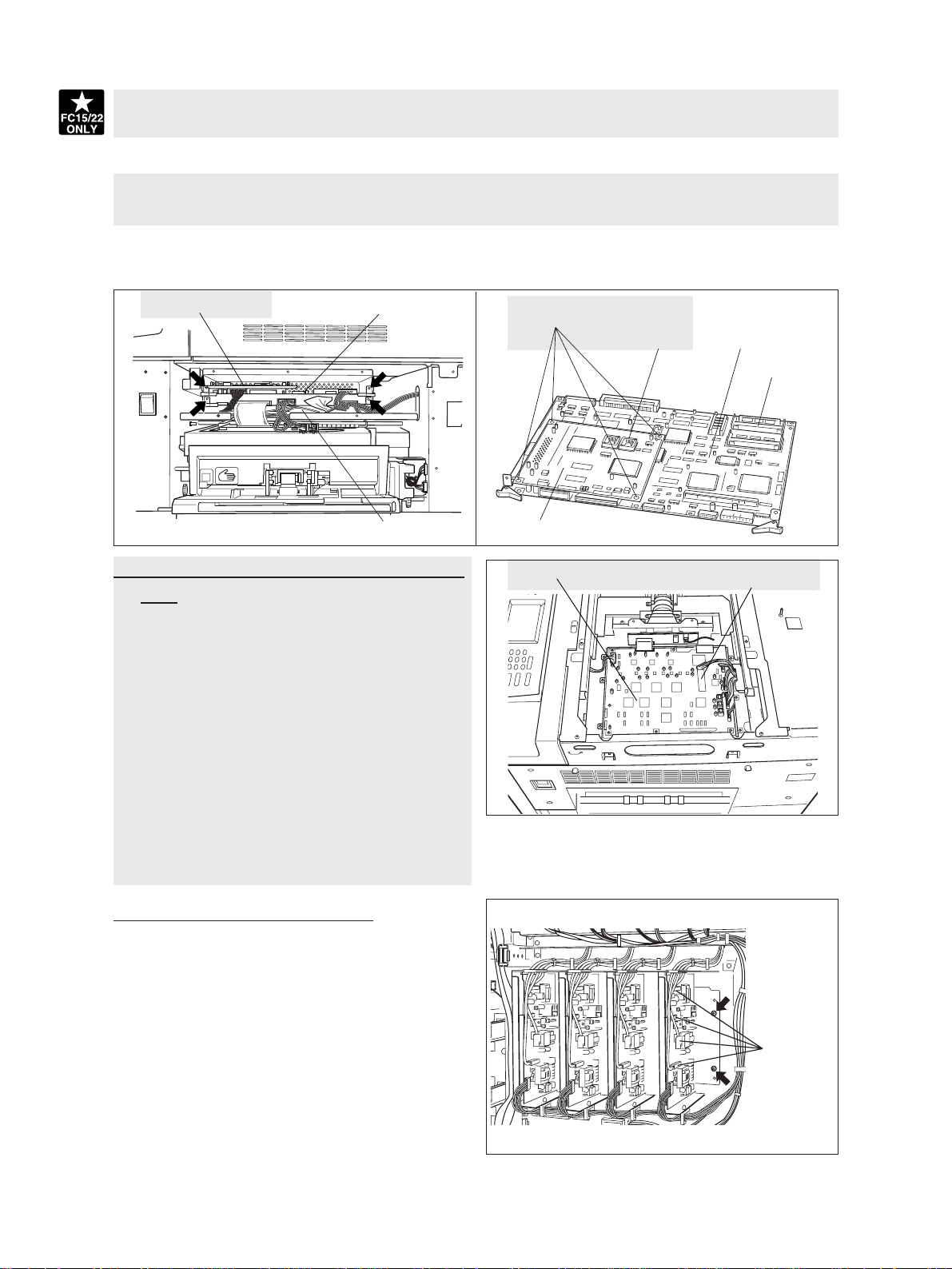
(5) Disconnect 4 connectors of the SIC board, unscrew 2 screws and take out the SIC board with the AI
board on it.
(6) Detach the SYS-ROM (J190) from the SIC board.
(7) Detach the AI-ROM (IC8) from the AI board.
(8) Remove 4 lock supports and detach the AI board from the SIC board.
(9) Disconnect 5 connectors of the IMC board, unscrew 2 screws and take out the IMC board.
(10)
Detach the IMC-ROM (IC30) from the IMC board.
AI board
SIC board
IMC board
[C] SCM board (Scanner Control Board)/SCM-
ROM
(1) Remove the glass retainer (2 screws).
(2) Remove the original glass.
(3) Remove the right top cover (3 screws).
(4) Remove the right top bracket (3 screws).
(5) Remove the lens cover (9 screws and
connector(s)).
(6) Detach the SCM board, disconnecting 11 con-
nectors and unscrewing 8 screws.
(7) Detach the SCM-ROM (IC19) from the SCM
board.
* See Chapter 9 for the detail on the above procedure.
Lock supports
AI board
SCM board
AI-ROM
SIC board
SYS-ROM
SCM-ROM
[D] Main high-voltage transformer
(1) Remove the rear cover.
(2) Disconnect 5 connectors.
(3) Unscrew 2 screws and remove the main high-
voltage transformer together with its bracket.
(4) Remove 2 screws and 2 lock supports and take
Connectors
out the main high-voltage transformer.
* All 4 transformers should be removed using the
same procedure.
January 2000 © TOSHIBA TEC 2 - 31 FC-22 OUTLINE OF THE MACHINE
Page 25
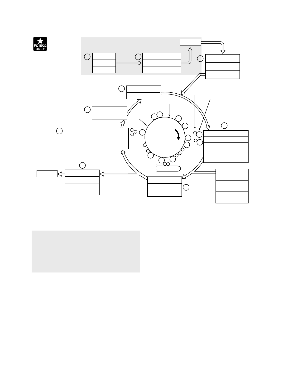
3.2 General Description of Copying Process
Image
processing
Paper exit
Original exposure
2 3
Halogen lamp
Discharge LED array
9
Wavelength 660 nm x24 pcs
8
Conductive blade cleaning
–700 VDC
1.0 kV/500 Hz AC
7
Fusing
Heat roller
500 W x1, 400 W x1 (115V, 127V)
570 W x1, 460 W x1 (200V series)
180 W
1
Charger (grid voltage)
–550V (–250~–1000V)
–
–
–
–
Data reading (scanning)
CCD
x
600-dpi, 7500 pixel
–
–
3
Photoconductive drum
–
–
– –
++++
–
–
–
–
Separation/transfer
700~1500 W
(600~4800)
4
Toner
Data writing
Semiconductor laser
Pw=10.4 nJ/mm
Carrier
2
–
–
+
–
++
+
–
+
–
++
+
–
–
–
6
5
Development
Magnetic roller
Bias –400 VDC
(–100 ~ –700)
1.2 kV/4kHz AC
Bypass feeding
(50 sheets)
LCF feeding
(1500 sheets)
Cassette feeding
(600 sheets for each)
1 Charging: Places a negative charge on the sur-
face of the photoconductive drum.
x
2
Original exposure: Converts images on the
original into optical signals.
x
3
Data reading: The optical image signals are
read into CCD and converted into electrical signals.
x
4 Data writing: The electrical image signals are
changed to light signals (by laser emission)
which expose the surface of the photoconductive drum.
x
5 Development: Negatively-charged toner is
made to adhere to the photoconductive drum,
producing a visible image.
x
6 Transfer/separation: Transfers the visible toner
image onto paper, and separates the paper with
the toner image from the photoconductive drum.
x
7 Fusing: Fuses the toner image to the paper by
applying heat and pressure.
x
8 Conductive blade cleaning : While scraping off
the residual toner from the drum, this blade also
eliminates the (+) residual charge on the drum
left after image transfer.
x
9 Discharge LED array: Eliminates the residual
(–) charge from the surface of the photoconductive drum.
FC-22 COPY PROCESS 3 - 2 January 2000 © TOSHIBA TEC
Page 26

(3) Data reading (scanning)
Data reading is the process of illuminating the original with light and converting the reflected light into
electrical signals.
CCD board
The light reflected from the original is directed to
the charge coupled device (CCD) and this optical
image information is converted to electrical signals
(image signals), which are then sent to the image
processing section via the scanner control PC
board.
The CCD for color processing has RGB filters provided over its surf ace, which allow the CCD to read
the light amount in the respective ranges of wavelength. The image data corresponding to the respective RGB colors is then sent to the image
processing section.
(Example)
CCD light
receiving
amount
Light 255
Dark 0
Scanner control
PC board
Image processing
section
Value of image
signals to be
output
Difference between "light "
and "dark" is divided into
256 steps.
(4) Data writing
Data writing is the process of converting the image
signals
light signals and exposing the drum surface with
the light signal.
Namely, the image signals sent from the image
processing section are converted into optical signals (laser emission) by the semiconductor laser
element, which are then used to expose the drum
surface, thus forming an electrostatic latent image
there.
sent from the image processing section
into
Drum K
Image processing section
Laser drive PC board
Semiconductor laser element
Polygonal mirror
Drum Y
Drum MDrum C
FC-22 COPY PROCESS 3 - 4 January 2000 © TOSHIBA TEC
Page 27

4. GENERAL OPERATION
4. 1 Overview of Operation
Copier operation Operation during warming-up, pre-running and standby
Automatic paper feed copying with the ST AR T k ey
Copy operation Bypass paper feed copying
Interrupt copying
4. 2 Description of Operation
4. 2. 1 Warming-up
(1) Initializing operation
• Power ON
• Fuser lamp ON
• Copy counter “1”/ “WAIT WARMING UP” displayed.
• Fan motors ON
• Initializing of the scanner system:
~ The carriage moves to and stops at its home position.
~ The carriage moves to the peak detection position.
~ The exposure lamp ON~Peak detection (white color detection based on the shading correction
plate)~The exposure lamp OFF.
~ The original size indicator initializes, then displays the original size.
• Initialization of the paper feeding system:
~ The tray of each cassette rises.
~ The guides of the ADU (automatic duplexing unit) detect their home positions, then mo ve to their
maximum-size position.
• Initialization of the laser optical system:
~ The polygonal motor rotates.
• Drum rotation:
~ Drum motors ON, transfer belt motor ON, color de veloper motor ON and b lack de veloper motor
ON.
• Toner supply control:
~ If the toner density in any developer unit is lower than specified, the toner supply mode starts.
• Image quality control:
~ Test patterns are formed on the transfer belt, and based on their reflection factors, the optimal
conditions are set.
• Others:
~ The main charger wire cleaners operate.
• Color registration control:
~ Test patterns are formed on the transfer belt and their signals are read to detect if toner is
present or not. This information is used to correct registrational deviation of each color.
January 2000 © TOSHIBA TEC 4 - 1 FC-22 GENERAL OPERATION
Page 28

(2) Pre-running operation
When the fuser roller has reached a certain temperature, pre-running operation is performed. (If the fuser
roller is already warm enough, this operation does not take place.)
• The fuser motor rotates.
(3) When the fuser roller reaches a temperature capable of fusing:
• Fuser lamp OFF
• Copy counter “1” / “READY” displayed.
4. 2. 2 Standby state (ready for copying)
• All keys on the control panel are operable.
• If no key is pressed for a certain period of time:
~Copy counter “1”, reproduction ratio “100%” and other defaults are set.
• A fixed time after the warming-up has ended.
~Color registration control
4. 2. 3 Cassette feed copying
(1) START key ON
• Display: “READY”→“COPYING”
• In black print, the transf er belt performs its release operation and the suction charger bias is turned
ON.
• The main chargers, developer bias, discharge LEDs and cleaning blade bias are turned ON. The
fan motors and polygonal motor rotate at high speed.
• The drum motors, transfer belt motor, fuser motor and developer motors rotate.
(2) Cassette paper feeding
• The feed motor, feed path clutch and feed clutch for the selected cassette are turned ON:
~ The pick-up roller, feed roller, separation roller, and transport roller rotate.
• The jam sensor for the selected cassette is turned ON, which then turns the feed clutch OFF.
• A sheet of paper reaches the registration roller:
~ Aligning operation takes place.
(3) Carriage operation
• Exposure lamp ON→Shading correction
• Scan motor ON→Carriages 1 and 2 start moving forward.
(4) A fixed time after the carriage operation,
• Registration motor ON→Transports the paper to the transfer section.
• The copy counter operates.
(5)A fixed time after the registration motor has been turned ON, toner supply operation is performed in
the order of Y, M, C and K, and then the transfer roller bias is turned ON.
FC-22 GENERAL OPERATION 4 - 2 January 2000 © TOSHIBA TEC
Page 29

(6) Carriage scanning completion
• Scan motor OFF
• Exposure lamp OFF
• Registration motor OFF (after the trailing edge of the paper has passed the registration roller)
(7) Paper exit operation
• The trailing edge of the paper is detected by the exit sensor.
• The main chargers, developer bias and discharge LEDs are turned OFF.
• The drum motors, transfer belt motor , fuser motor and de veloper motors stop their oper ations. The
fan motors and polygonal motor return to their standby rotations.
• “READY” is displayed and the copier goes into standby.
January 2000 © TOSHIBA TEC 4 - 3 FC-22 GENERAL OPERATION
Page 30

Timing chart for copying two A4 sized sheets fed from the 2nd cassette
Scan motor
Feed motor
Feed clutch
Drum motor
(Y, M, C, K)
Transfer belt motor
Color developer motor
Black developer motor
Main charger
wire/grid (Y, M, C, K)
Developer bias (Y, M, C, K)
Transfer roller bias (Y)
Transfer roller bias (M)
Transfer roller bias (C)
Transfer roller bias (K)
Discharge LED
Cleaning blade bias
Registration sensor
Registration clutch
Exit sensor
Fuser motor
FC-22 GENERAL OPERATION 4 - 4 January 2000 © TOSHIBA TEC
Page 31

4. 2. 4 Bypass feed copying
(1) Insertion of paper in the bypass tray
• Bypass paper sensor ON:
~ “Ready for bypass feeding” is displayed.
• The carriage moves to its home position.
(2) Pressing of the START key
• “Reasy for bypass feeding”→”COPYING” displa y
• The main chargers, dev eloper bias and discharge LEDs are turned ON. The f an motors rotate and
polygonal motor rotates at high speed.
• The drum motors, developer motors, transfer belt motor and fuser motor rotate.
(3) Bypass paper feed operation
• The feed motor, feed path clutch and bypass feed clutch are turned ON:
~ The bypass pick-up roller lowers.
~ The bypass pick-up roller and bypass feed roller rotate.
• Aligning operation
• When the paper arrives at the registration sensor, the bypass feed clutch is turned OFF.
• The paper arrives at the registration roller.
(4)Hereafter, the same operation as described in (3) to (6) of “4.2.3 Cassette f eed copying” is perf ormed.
4. 2. 5 Interruption copying
(1) Pressing of the INTERRUPT key
• The INTERRUPT lamp is turned ON.
• The copying operation now in progress is stopped temporarily. Carriages 1 and 2 return to their
preset positions.
• “Job interrupted job 1 saved” is displayed.
• The center step of manual density and the 100% reproduction ratio are set. The cop y quantity does
not change.
(2) Selection of the desired copy modes
(3) After interruption copying is finished,
• “Press INTERRUPT to resume job 1” is displayed.
• Pressing the INTERRUPT ke y turns the INTERRUPT lamp OFF, returning the copier to the condition before the interruption.
• “Ready to resume job 1” is displayed.
(4)Pressing the START key
The copying operation before interruption is resumed.
January 2000 © TOSHIBA TEC 4 - 5 FC-22 GENERAL OPERATION
Page 32

4. 4. 2 Automatic paper feed copying
START key: ON
Processing system control
Polygonal motor rotates at
high speed.
Polygonal motor
rotating normally?
YES
(Y, M, C and K units)
Developer bias: ON
Main charger wire/grid: ON
Cleaning blade bias: ON
Discharge LED: ON
Laser: ON
Transport system control
Black
copy mode?
NO
YES
Call for service
"CA1"
Transport belt
release operation
Drum motors Y, M, C, and K: ON
Transfer belt motor: ON
Feed motor: ON
Fuser motor: ON
Black developer motor: ON
Color developer motor: ON
Feed path clutch: ON
Feed clutch: ON
Jam sensor ON?
Scanner system control
NO
E
Exposure lamp: ON
D
NO
NO
Call for
service
"CA2"
H-Sync OK?
YES
YES
Feed clutch: OFF
Registration
sensor ON?
YES
Feed path clutch: OFF
BA C
A fixed period
of time passed?
YES
Paper jam
"E12~E16, E19"
NO
A fixed period
of time passed?
YES
Paper jam
"E21~E26"
NO
NO
January 2000 © TOSHIBA TEC 4 - 13 FC-22 GENERAL OPERATION
Page 33

8. DISPLAY UNIT
8.1 Detailed Drawing of the Control Panel and the Display Panel
8.1.1 Control Panel and Display Panel for FC-22/15
The display unit consists of key s witches and touch-panel s witches for copier oper ation/selection of each
mode, LEDs and an LCD displaying the copier state or messages.
When the operator’s attention is needed, a graphic symbol lights or flashes and a message indicating
that particular condition is displayed in the LCD panel.
BLACK
FULL COLOR
AUTO COLOR
HELP
TIMER
SETTINGS
ENERGY
SAVER
INTERRUPT
Layout of the control panel
ACCESS
CLEAR
FUNCTION CLEAR
STOP
START
LCD panel display calling for operator's attention
January 2000 © TOSHIBA TEC 8 - 1 FC-22 DISPLAY UNIT
Page 34

8.1.2 Control Panel and Display Panel for FC-25P
The display unit is comprised of touch-panel switches and ke y switches , which are used for oper ating the
printer and selecting various modes, and LEDs and LCDs, which are used to display the machine status
(various modes included) and messages. Normally, only messages are shown on the LCD. However,
when the operator needs to be alerted, a corresponding pictorial is lit or flashed on the LCD with a
message describing the associated status at the same time.
The main unit is equipped with the same control panel as that on the copier. This allows you to do the
same operation as with the copier, when making v arious adjustments during installation. After the adjustment are finished, attach the control-panel cover which came pack ed. Only the service technician should
install or remove the control-panel cover.
Layout of the control panel
LCD panel display calling for operator's attention
January 2000 © TOSHIBA TEC 8 - 1 - 1 FC-22 DISPLAY UNIT
Page 35

8.2 Items Shown on the Display Panel
8.2.1 Display during normal copying (for FC-15/22)
No. Message
1 Wait Warming Up
2 READY
3 COPYING
4 Saving energy
- press START
5 Place next original
Press PRINT (START)
to copy
Conditions of machine
Being warmed up
•
Displayed after the main switch is
turned ON up until the machine
becomes ready for copying.
Standby for copying.
•
The machine is ready for copying
and operator’s instructions on
copying conditions can be input.
•
Returns to the default condition if
no key is pressed for 45 seconds.
Now copying.
•
Displayed by pressing the START
key.
•
Copy quantity indicator becomes
“1” and copying is completed.
Energy saver mode.
ADU back-side copying standby
state.
Notes
•
When the main switch comes ON, the
quantity and reproduction ratio of
copies are indicated, for example, as
“1”, “100%”.
•
Copy quantity indicator shows “1”.
When a digital key is pressed, that
number indicates the set quantity.
•
The set quantity can be cleared to “1”
by pressing the CLEAR key.
•
Bypass copying is possible.
•
After completion of copying, the copy
quantity indicator returns to the
initially set number.
•
Reset by pressing the ENERGY
SAVER key or the START key.
•
When using ADF one-sided, and
when not using ADF.
6—
Timer OFF
•
No message is displayed in the
display panel.
•
Timer LED is turned ON.
C
•
Press the START key to clear.
Fig. 8.2-1
FC-22 DISPLAY UNIT 8 - 2 January 2000 © TOSHIBA TEC
Page 36

8.2.2 Display in the event of faulty conditions (for FC-15/22)
No. Message
7 Add Paper
8 Install new X toner
cartridge
(X: Y, M, C, K)
9 Set key copy counter
10 Dispose of used toner
Abnormal state & indication
Indication of lack of paper.
•
Flashes when there is no paper in
the cassette (A in Fig. 8.2-2).
•
Bypass copying is possible.
Indication of lack of toner.
•
B in Fig. 8.2-2 is displayed when
the toner in the toner cartridge
becomes empty .
•
When this message is displayed, it
is not possible to copy.
Key copy counter withdrawn.
•
Displayed when the key copy
counter is withdrawn when the
machine is READY or during
copying. C in Fig. 8.2-1.
•
When it is removed after the
pressing of the START key, the
machine stops after that copy is
completed, but the counter counts it.
Indication of need to replace the
toner bag.
• Displayed when the toner bag is
full. D in Fig. 8.2-2.
The copier stops.
Solution
•
Supply paper to the selected cassette.
•
Select another cassette.
•
Reset after the toner is supplied and
the front cover is closed.
•
Reset and returned to normal conditions by inserting the key copy
counter.
•
Open the front covers, replace the
toner bag, and then close the front
covers to reset.
B
D A
Fig. 8.2-2
January 2000 © TOSHIBA TEC 8 - 3 FC-22 DISPLAY UNIT
Page 37

8.2.3 Display during normal copying (for FP25P)
No. Message
1 Wait Warming up
2 ONLINE
3 OFFLINE
4 PRINTING
5 Saving energy
- press ONLINE
Conditions of machine
During wariming up
Shown when the power switch is
turned on and continues to be shown
until printing becomes ready.
Printing ready
Shown when printing becomes ready,
wating for a print job form the printer
controller.
Placed in setting mode
Various settings can be made but
printing is disabled.
Print operation proceeding
Displayed when a print job is received from the printer controller.
Under energy saving mode
Notes
When the power switch is truned ON,
only the message is shown. (Fig. 8.2-3)
Only the message is shown.
(Fig. 8.2-4)
The basic screen is displayed.
(Fig. 8.2-5)
After settings are made, pressing the
ONLINE key again will return to the
ONLINE display.
After printing, the ONLINE display
returns.
Only the message is shown.
When a print job is received from the
printer controller, the energy saving
mode will automatically be cleared.
Press the ONLINE key to go into the
OFFLINE mode, and the energy saving
mode will be cleared.
(Fig. 8.2-3) (Fig. 8.2-4)
(Fig. 8.2-5)
January 2000 © TOSHIBA TEC 8 - 5 - 1 FC-22 DISPLAY UNIT
Page 38

8.2.2 Display in the event of faulty conditions (for FC-25P)
No. Message
6 Add Paper
7 Install new X toner
cartridge
(X: Y, M, C, K)
8 Dispose of used toner
Abnormal state & indication
Indication of lack of paper.
•Flashes when there is no paper in
the cassette (A in Fig. 8.2-6).
•Bypass copying is possible.
Indication of lack of toner.
•B in Fig. 8.2-6 is displayed when
the toner in the toner cartridge
becomes empty .
•When this message is displayed, it
is not possible to print.
Indication of need to replace the
toner bag.
• Displayed when the toner bag is
full. C in Fig. 8.2-6.
The copier stops.
Solution
•Supply paper to the selected cassette.
•Select another cassette.
•Reset after the toner is supplied and
the front cover is closed.
•Open the front covers, replace the
toner bag, and then close the front
cover.
Fig. 8.2-6
January 2000 © TOSHIBA TEC 8 - 5 - 2 FC-22 DISPLAY UNIT
Page 39

No. Message
Abnormal state & indication
Solution
9 Paper misfeed in
bypass
10 Misfeed in printer
11 Misfeed in printer
12 Misfeed in finisher
13 Misfeed in duplexer
14 Call for service
Bypass paper jamming
•Paper jams at the bypass guide. A
in Fig. 8.2-7.
Paper jammed in the machine.
B in Fig. 8.2-7.
Cassette paper misfeed.
•Paper supplied from the cassette
does not reach the aligning sensor
in a set time.
C in Fig. 8.2-7.
Paper jammed in the finisher.
D in Fig. 8.2-7.
Paper jammed in the ADU .
E in Fig. 8.2-3.
Some part of the mechanism,
motors, switches or sensors is
abnormal. F in Fig. 8.2-7.
The machine returns to normal conditions automatically when the paper out
is pulled from the bypass guide.
Press the HELP/INFO key and remove
the paper jammed in the priner by
following the messages.
Press the HELP/INFO key and remove
the paper jammed in the priner by
following the messages.
Remove the paper jammed in the
finisher and open and close the front
cover for once.
Press the HELP/INFO key and remove
the paper jammed in the priner by
following the messages.
Turn OFF the machine, remove the
cause of the fault and turn the machine
back ON.
15 Time for periodic
maintenance (XXXX)
(XXXX: colo(u)r, black)
Indication of PM cycle.
•Displayed when it is time for
preventive maintenance and
inspection.
•Capable of printing.
Maintenance and inspection by a
qualified service technician.
Fig. 8.2-7
January 2000 © TOSHIBA TEC 8 - 5 - 3 FC-22 DISPLAY UNIT
Page 40

8.3 Relation between Copier Conditions and Operator’s Actions
Operation
START CLEAR STOP Di
g
ital RPR-RATIO DENSITY ORIGINAL COPYSIZE Cassette INTERRUPT ENERGY
ONLINE Bypass Touch
COLOR ACCESS CONFIRM
Status
key key key key key key SIZE key key sellection key SAVER key
key feeding panel
MODE
ke
y
ke
y
ke
y
Warming Up
○○−○○○○○○○○
−−
−−
○○
○○○
Ready for copying
○○−○○○○○○○○
//
//
○○○○○
Reproduction ratios being switched
−○−○○○○○○○○
//
//
○○○○○
Copying operation
−−○−−−−−−−−
//
//
−
*1
−−−○
Paper being added
−○−○○○○○○○○
○○
○○
○○
Toner being added
−
*2
○−○○○○○○○○
○○
○○
○○
Key copy counter not inserted
−○−○○○○○○○○
//
//
○○○○○
Papermisfeed in bypass copying
−−−−−−−−−−−
−−
−−
−−
Toner bag being replaced
−−−−−−−−−−−
−−
−−
−−
Paper jammed inside the machine
−−−−−−−−−−−
−−
−−
−−
−−−
Service call indicated
−−−−−−−−−−−
−−
−−
−−
Ready for interrupt copying *3
○−−−○○○○○○−
//
//
○○○○−
Ener
gy
saver mode activated
*4
*5
○−−−−−−−−−○
○○
○○
−−
ONLINE status indicated //
//
//
//
//
//
//
//
//
//
//
//
//
//
//
//
//
//
//
//
//
//
○○
○○
○○
○○
−−
−−
//
//
//
//
//
//
Printing Operation //
//
//
//
//
//
//
//
//
//
//
//
//
//
//
//
//
//
//
//
//
//
−−
−−
−−
−−
*1 −−
−−
//
//
//
//
//
//
OFFLINE status indicated //
//
//
//
//
//
//
//
//
//
//
//
//
//
//
//
//
//
//
//
//
//
○○
○○
○○
○○
○○
○○
//
//
//
//
//
//
is only for FC15/22 ○:O
p
eration available
is only for FC25P −:O
p
eration unworkable
/:O
p
eration non-sur
p
ort
*1 Avoid b
yp
ass insertion durin
g
co
py
in
g
o
p
eration and
p
rintin
g
o
p
eration since this ma
y
result in
p
a
p
er
j
ammin
g
.
*2 Black mode is available while color toner is all use up.
*3 Interruption condition is automatically released if the machine is not used 45 sec.
*4 Ener
gy
saver mode is released b
y
p
ressin
g
theENERGY SAVER ke
y
or the START ke
y
(
for FC15/22 O
p
eration
)
*5 Energy saver mode is released by pressing theONLINE key or starting a Print job .(for FC25P Operation)
○○○
○○○
−−−
−−−
−−−
−−−
FC-22 DISPLAY UNIT 8 - 6 January 2000 © TOSHIBA TEC
Page 41

(3) PWA-F-IMC-310/313
January 2000 © TOSHIBA TEC 18 - 3 FC-22 PC BOARDS
Page 42

In this manual, colors are sometimes described using abbreviations as listed below:
Yellow : Y Magenta : M Cyan : C Black : K
1. ADJUSTMENT ITEMS
1.1 Error Code List
While the “CLEAR PAPER” or “CALL SERVICE” symbol is flashing, pressing the [CLEAR] key and
the [8] key on the digital keys at the same time shows one of the following error codes on the copyquantity indicator as long as those keys are pressed.
Classification
Paper transport jam inside the copier
Paper feeding jam E11 Paper misfeed from the ADU
Paper transport jam
(Paper not reaching the registration
sensor after feeding)
Cover open jam E41 Front cover opened during copying
Paper jam in ADU and reversing
area
Error code
E01 Paper leading edge not reaching the exit sensor
E02 Paper trailing edge not passing the exit sensor
E03 Paper remaining inside the copier at power ON
EB7 Restart time out error
E12 Paper misfeed from the bypass
E13 Paper misfeed from the 1st cassette
E14 Paper misfeed from the 2nd cassette
E15 Paper misfeed from the 3rd cassette
E16 Paper misfeed from the 4th cassette
E19 Paper misfeed from the LCF
E21 Paper transport jam from the LCF
E22 Paper transport jam from the 1st cassette
E23 Paper transport jam from the 2nd cassette
E24 Paper transport jam from the 3rd cassette
E25 Paper transport jam from the 4th cassette
E42 Side door opened during copying
E43 ADU unit pulled out during copying
E45 LCF jam access cover opened during copying
E46 Bypass unit opened during copying
E50 Paper not reaching the ADU
E51 Paper not restarting from the ADU stack
E52 Paper not reaching the ADU path sensor
E54 ADU paper transport jam
Content
January 2000 © TOSHIBA TEC 1 - 1 FC-22 ADJUSTMENT
Page 43

Classification
Error code
Content
Original jam in the ADF E71 Original not reaching the aligning sensor
E72 Original not reaching the exit sensor
E73 Original not passing the exit sensor
E75
Second original not reaching the aligning sensor in 2-in-1 mode
E79 Original pre-feeding jam
Paper jam in the sorter EA1 Paper transport delay jam
EA2 Paper transport stop jam
EA3 Paper remaining on the sorter transport path at power on
EA4 Sorter front door opened during copying
EA5 Staple jam
Paper jam in the sorter EA6 Finisher/sorter early-arrival jam (P30) (internal)
EA8 Finisher saddle staple jam
EA9 Finisher saddle door open
EAA Finisher saddle power ON jam
EAB Finisher saddle delivery delay
EAC Finisher saddle delivery failure
Special sheet jam EC2 OHP sheets used except from bypass and 2nd cassette
EC3 OHP sheet used in non-OHP mode
Drive system related service call C05 ADU motor rotation abnormal
Paper feeding system related
service call
Scanner related service call C27
C09 Black developer motor rotation abnormal
C0A Color developer motor rotation abnormal
C0B Drum motor K rotation abnormal
C0C Drum motor C rotation abnormal
C0D Drum motor M rotation abnormal
C0E Drum motor Y rotation abnormal
C11 ADU paper side guide function abnormal
C12 ADU paper end guide function abnormal
C13 1st cassette tray function abnormal
C14 2nd cassette tray function abnormal
C15 3rd cassette tray function abnormal
C16 4th cassette tray function abnormal
C18 LCF tray function abnormal
Carriage home position sensor not turning OFF within a fixed time
C28
Carriage home position sensor not turning ON within a fixed time
C29 Exposure lamp disconnection detected
FC-22 ADJUSTMENT 1 - 2 January 2000 © TOSHIBA TEC
Page 44

Classification
Copy process related service call C31 Used toner transport motor rotation abnormal
Error code
C33 Developer removal shutter function abnormal
C35 Transfer belt unit contact/release function abnormal
C37 Transfer belt moter rotation abnormal
C38 Auto toner initializing error (K)
C39 Auto toner initializing error (C)
C3A Auto toner initializing error (M)
C3B Auto toner initializing error (Y)
C3C Main charger wire abnormal (K)
C3D Main charger wire abnormal (C)
C3E Main charger wire abnormal (M)
C3F Main charger wire abnormal (Y)
Content
January 2000 © TOSHIBA TEC 1 -2 - 1 FC-22 ADJUSTMENT
Page 45

Classification
Fuser unit related service call C41
Communications related service call C57 Communications error between Main-CPU and Sorter-CPU
Error code
Thermistor or heater abnormal when warming-up is started
C42 Thermistor abnormal after the copier becomes ready
C43 Thermistor abnormal during warming-up after abnormality
judgment
C44 Heater abnormal during warming-up after abnormality
judgment
C46 Heater abnormal (low temperature) after the copier has
become ready
C47 Rear thermistor abnormal after the copier has become
ready
C48 Heater abnormal (high temperature)
C7 Error C7
C5A
C5B Main-CPU signal transmission error to IMC-CPU
C5C Main-CPU signal reception error from IMC-CPU
Communications error between Main-CPU and printer controller
Content
ADF related service call C72 Error of aligning sensor automatic adjustment
C73 EEPROM initializing error
C74 Error of paper exit sensor automatic adjustment
Other service calls C94 Main-CPU abnormal
C9A Main memory abnormal
C9E IMC board connection abnormal
Laser optical unit related service call
CA1 Polygonal motor rotation abnormal
CA2 H-SYNC abnormal
CD1 Laser calibration error (K)
CD2 Laser calibration error (C)
CD3 Laser calibration error (M)
CD4 Laser calibration error (Y)
January 2000 © TOSHIBA TEC 1 - 3 FC-22 ADJUSTMENT
Page 46

Classification
Sorter related service call CB1 Delivery motor abnormal
Sorter related service call
Error code
CB2 Paper exit motor abnormal
CB3 Tray-up motor abnormal
CB4 Alignment motor abnormal
CB5 Staple motor abnormal
CB6 Staple unit shift motor abnormal
CB7 Stack detection sensor abnormal
CB8 Backup RAM data abnormal
CB9 Saddle push motor abnormal
CBA Saddle outer staple motor abnormal
CBB Saddle inner staple motor abnormal
CBC Saddle alignment motor abnormal
CBD Saddle guide motor abnormal
CBE Saddle folding motor abnormal
CBF Saddle positioning plate motor abnormal
CC0 Sensor connector connection abnormal
CC2 Micro-switch abnormal
Content
CC1 Transport motor rotation abnormal
CC3 Bin shift motor rotation abnormal
CC4 Guide bar swing motor rotation abnormal
CC5 Staple-unit swing motor rotation abnormal
CCA Automatic adjustment error of bin inside paper sensor
CCC No power being supplied
Image quality related service call CE1 Image quality sensor abnormal (OFF level)
CE2 Image quality sensor abnormal (no pattern level)
CE4 Image quality control test pattern abnormal
CE5 Temperature/humidity sensor upper-limit abnormal
CF1 Color registation control abnormal
January 2000 © TOSHIBA TEC 1 -3 - 1 FC-22 ADJUSTMENT
Page 47

Classification
Options related service call F07 Communications error between System-CPU and Main-CPU
Image processing options related
service call
Error code
F11
Communications error between System-CPU and Scanner-CPU
Content
F51 Communications error between System-CPU and AI-board
during pre-scanning
FC-22 ADJUSTMENT 1 - 4 January 2000 © TOSHIBA TEC
Page 48

<<Error history>>
Under code 253 in the setting mode (08), the latest eight groups of error data will be displayed.
Display example
EA1 99 08 26 17 57 32 64 64 236210000000
Error code
3 digits 12 digits 3 digits 3 digits 12 digits
A Paper source
0:Not fixed 1:Bypass feed 2:LCF 3:1st 4:2nd 5:3rd 6:4th 7:ADU feed
B Paper size code
0:A5/ST 1:A5-R 2:ST-R 3:LT 4:A4 5:B5-R 6:LT-R 7:A4-R 8:OTHER/UNIV 9:B5
A:FOL/COM B:LG C:B4 D:LD E:A3 Z:Not selected
YY MM DD HH MM SS
MMM NNN
ABCDEFHIJLOP
C Sort mode
0:Not selected 1:Group 2:Sort 6:Staple sort
D DF mode
0:Unused 1:AUTO FEED (SADF) 2:STACK FEED
E APS/AMS mode
0:Not selected 1:APS 2:AMS
F Duplex mode
0:Not selected 1:BOOK 2:T wo-sided/Single-sided 4:T wo-sided/Duple xed 8:Single-sided/Duplex ed
G Unused
H Binding space
0:Unused 1:BOOK 2:LEFT 4:RIGHT
I Editing
0:Unused 1:Masking 2:Trimming 3:Mirror image 4:Negative/Positive
J Edge erase/Dual-page
0:Unused 1:Edge erase 2:Dual-page 3:Edge erase & Dual-page
K Unused
L Function
0:Copying 1:Unused (Extended copying) 2:Unused (Fax input) 3:Unused (Fax printing)
4:Printing 5:Unused (DSS)
MMM Primary-scanning reproduction ratio (Display in hexadecimal)
(Mx256)+(Mx16)+M
NNN Secondary-scanning reproduction ration (Display in hexadecimal)
(Nx256)+(Nx16)+N
O Color mode
0:Auto color 1:Full color 2:Black 3:Monocolor
P AI board
0:Unused 1:Used
January 2000 © TOSHIBA TEC 1 - 5 FC-22 ADJUSTMENT
Page 49

[FULL COLOR]key: OFF, [AUTO COLOR]key: ON, [ENERGY SAVER]key: ON
Digital key Icon Item Condition
1——
2 — Color registration sensor (front)
3 — Color registration sensor (rear)
4 — Image quality sensor
5——
A ADF aligning sensor 1: Original exist
B ADF exit sensor 1: Original exist
C ADF open/close sensor 1: ADF is open
D ADF empty sensor 1: Original exist
6
E ADF size sensor 1
F—
G ADF size sensor 2
H ADF unit is installed or not 1: ADF unit is installed
A—
B Direct control-panel connection detection
C Connection
D Installation
7
E—
F Carriage home position sensor 1: Carriage is home position
G Direct control-panel SW-F key (during debugging)
H Platen sensor 1: Platen cover is closed
A—
B—
C—
D APS sensor (APS-R) 1: Original exist
8
E APS sensor (APS-C) 1: Original exist
F APS sensor (APS-3) 1: Original exist
G APS sensor (APS-2) (for A4 series) 1: Original exist
H APS sensor (APS-1) 1: Original exist
9 — Scanner SCM board input 24V check Output value is displayed with 8 bit.
0 — Thermistor check
Sensor output value is displayed with 8 bit.
Sensor output value is displayed with 8 bit.
Sensor output value is displayed with 10 bit.
—
January 2000 © TOSHIBA TEC 1 - 13 FC-22 ADJUSTMENT
Page 50

Code Function Procedure
261 Discharge LED (M) ON/OFF 3
262 Discharge LED (C) ON/OFF 3
263 Discharge LED (K) ON/OFF 3
280 Laser (Y) ON/OFF 3
281 Laser (M) ON/OFF 3
282 Laser (C) ON/OFF 3
283 Laser (K) ON/OFF 3
300 Carriage fan motor rotation when standby (low speed) ON/OFF 3
301 Carriage fan motor rotation when running (high speed) ON/OFF 3
302 SCM fan motor rotation speed Low/High 3
304 Scanner exposure lamp ON/OFF 4
331 ADF pick-up roller rotation ON/OFF 3
332 ADF aligning roller rotation ON/OFF 3
333 ADF transport-belt CW rotation ON/OFF 3
334 ADF transport-belt CCW rotation ON/OFF 3
351 Scan motor (carriage 1 reciprocating) 3
352 Document motor (indicator 1 reciprocating) 3
353 ADF single-sided original feeding 3
354 ADF two-sided original feeding 3
355 ADF original exiting 3
356 ADF 2 in 1 original feeding 3
January 2000 © TOSHIBA TEC 1 - 17 FC-22 ADJUSTMENT
Page 51

1. 2. 3 Test print mode (04)
(
)
In the 04 test print mode, you can print the test patterns matching with each item if you input the
following codes.
Code Types of test patter n Remarks
Paper size
11 2-pixel modulation pattern for creating γ table A3
12 3-pixel modulation pattern for creating γ table A3
13 1-pixel modulation pattern for checking γ table A3
14 2-pixel modulation pattern for checking γ table A3
15 3-pixel modulation pattern for checking γ table A3
24 Gray 2-pixel modulation pattern for checking γ table A3
25 Gray 3-pixel modulation pattern for checking γ table A3
204 Grid pattern (Printer reproduction ratio/Registration Pattern width: 1 dot, Pitch: 5mm A3/LD
adjustment pattern) (same as the adjustment pattern
by [05] mode [1][SETTINGS])
219 6% test pattern
220 8% test pattern None
230 Gradation check pattern (2 Pixels standard) Pattern width: 10mm, A3/LD
32 gradation steps
231 Gradation check pattern (3 Pixels standard) Pattern width: 10mm, A3/LD
32 gradation steps
234 Half tone A3/LD
256 Density check pattern A3/LD
291 2-pixel modulation pattern 1 for selecting pulse width A3
292 2-pixel modulation pattern 2 for selecting pulse width A3
Note: Full color (YMCK) mode is not available in 230, 231 and 234.
<Operation procedure>
0 4
POWER
Note: 1. When an error has occurred, it is indicated, but the recovery operation is not performed. So, tur n the
power OFF and then back ON to clear the error.
2. During test printing, when "Wait adding toner" is displayed, the [STOP] key is disabled.
January 2000 © TOSHIBA TEC 1 - 19 FC-22 ADJUSTMENT
(Code)
START
(Test print operation)
POWER OFF/ONSTOP
Exit
Page 52

1. 2. 4 Adjustment mode (05)
In the adjustment mode 05, the following adjustment items can be corrected, changed, or checked.
*In code No. column, number after hyphen means sub-code.
Code
104 128 1~255
Scanner (secondary scanning) copy length re-
Description/Mode
production ratio adjustment.
Default
Acceptable
Value
When the value increases by 1, the
reproduction ratio in the secondary
scanning direction (vertical paper
feeding direction) increases by
approx. 0.1522%.
105 128 85~171 When the value increases by 1, the
Scanner (secondary scanning) start position
deviation
image shifts by approx. 0.1213mm
toward the trailing edge of the paper.
106 For regular 180 5~251 When the value increases by 1, the
CCD primary scanning star t
position deviation
copy mode image shifts by approx. 0.042mm
toward the front side of the paper
(machine).
108 For whole-area 133 5~251 When you input a value, which is
copy mode 47steps (equivalent to2mm)
smaller than the set value of [106],
the rear original edge and thefront
copy edge match (0.042mm/step).
135 RADF original stop position (single-sided) 8 0~15 Changes the position where the
136 RADF original stop position 8 0~15 original stops.When the value in-
(reverse side of two-sided original) creases by 1, the original stop po-
sition shifts by 1 mm awa y from the
original stopper.
137 RADF sensor automatic adjustment and – – By pressing the START key, WAIT
EPROM Initialization is displayed while the automatic
adjustment is performed.
Perform RADF EPROM Initializa-
tion when EPROM, RADF logic
PWA or sensors are replaced.
142 RADF 2-in-1 gap adjustment 8 0~15 When the value increases by 1, the
gap between two originals extend
by 1 mm.
Contents
Operation
procedure
group
1
1
1
1
1
1
6
1
FC-22 ADJUSTMENT 1 - 20 January 2000 © TOSHIBA TEC
Page 53

Operation
procedure
group
Code
Description/Mode
Default
Acceptable
Value
Contents
482 Primary-scanning reproduction ratio (scanner) 127 112~142 When the value increases b y 1, the
reproduction ratio of the primary
scanning direction (paper feeding
in horizontal direction) decreases
by 0.082%.
484 1st cassette Y 6 0~15
Secondary-scanning data
485 2nd cassette Y 6 0~15
write start position adjust-
486 3rd cassette Y 6 0~15
ment (Copier)
487 4th cassette Y 7 0~15
When the value increases by 1, the
image shifts by approx. 0.6 mm to-
ward the trailing edge of paper feed
direction.
488 Bypass feed Y 6 0~15
489 LCF Y 7 0~15
490 ADU Y 7 0~15
500 Modulation mode switching, type A 0 0~255 1
501 Modulation mode switching, type B 0 0~255 1
502 Modulation mode switching, type C 0 0~255 1
503 Modulation mode switching, type D 0 0~255 1
504 Highlight processing ON/OFF 0 0~255 1
505 Screen angle change (Y) 0 0~255 1
506 Screen angle change (M) 0 0~255 1
507 Screen angle change (C) 0 0~255 1
508 Screen angle change (K) 0 0~255 1
509 Modulation data results indication 0
511
Density adjustment; density curve input, full color
8bit*4*4*5
0 0~255 4
512 Density adjustment; density curve selection, 0 0~255 1
full color
513 Density adjustment; density curve selection, 0 0~255 1
full color
514 Density adjustment; density curve selection, 0 0~255 1
full color
515 Density adjustment; density curve selection, 0 0~255 1
full color
516 Density adjustment; density curve selection, 0 0~255 1
full color
517 Density adjustment; density curve input, 0 0~255 1
monochrome
518 Density adjustment; density curve selection, 0 0~255 1
monochrome
519 Density adjustment; density curve selection, 0 0~255 1
monochrome
1
1
1
1
1
1
1
1
10
January 2000 © TOSHIBA TEC 1 - 25 FC-22 ADJUSTMENT
Page 54

Operation
procedure
group
Code
Description/Mode
Default
Acceptable
Value
Contents
520 Density adjustment; density curve selection, 0 0~255 1
monochrome
521 Density adjustment; density curve selection, 0 0~255 1
monochrome
522 Density adjustment; density curve selection, 0 0~255 1
monochrome
523 Color mode black text γ curve set selection 0 0~255 1
524 Color mode black text γ curve set selection 0 0~255 1
525 Color mode black text γ curve set selection 0 0~255 1
526 Monochrome mode black text
γ
curve set 0 0~255 1
selection
527 Monochrome mode black text γ curve set 0~255 1
selection
528 Monochrome mode black text
γ
curve set 0~255 1
selection
529 Monitor patch output ON/OFF switching 0~255 1
530 Filter coefficient set selection table – (0~99)*62 4
531 Scanner characteristic R for filter selection 0~8 1
532 Scanner characteristic G for filter selection 0~8 1
533 Scanner characteristic B for filter selection 0~8 1
534 Scanner correction color conversion matrix 0~15
selection
535 Basic color conversion matrix selection, type A 0~255 1
536 Basic color conversion matrix selection, type B 0~255 1
537 Basic color conversion matrix selection, type C 0~255 1
538 Basic color conversion matrix selection, type D 0~255 1
539 Operation of pre-scan unit only – 1
540 Operation equivalent to normal copying – 1
544 Automatic adjustment of scanner correction – –
color conversion matrix
545 Selection of scanner correction color 0 0:3 x 4 1:3 x 3 0
conversion matrix type
546 Indication of scanner correction color – –
conversion patch read data
547 Indication of scanner correction color –
32bit*3*10*9
conversion matrix calculation results
–
January 2000 © TOSHIBA TEC 1 -25-1 FC-22 ADJUSTMENT
Page 55

Operation
procedure
group
Code
550 Full color Text/Photo 128 0~255 1
"Manual density"
551 Text 128 0~255 1
fine adjustment
552 Printed image 128 0~255 1
(Center setting)
Description/Mode
Default
Acceptable
Value
When the value increases, images
made at center density become
darker.
Contents
553 Photo 128 0~255 1
554 Map 128 0~255 1
555 Black Text/Photo 128 0~255 1
556 Text 128 0~255 1
557 Printed image 128 0~255 1
558 Photo 128 0~255 1
559 Map 128 0~255 1
"Manual density"
560 Full color Text/Photo 20 0~255 1
fine adjustment
561 Text 20 0~255 1
(Darker setting)
562 Printed image 20 0~255 1
When the value increases, images
made at the “dark” side become
darker.
563 Photo 20 0~255 1
564 Map 20 0~255 1
565 Black Text/Photo 20 0~255 1
566 Text 20 0~255 1
567 Printed image 20 0~255 1
568 Photo 20 0~255 1
569 Map
20 0~255 1
FC-22 ADJUSTMENT 1 -25-2 January 2000 © TOSHIBA TEC
Page 56

Operation
procedure
group
Code
"Manual density"
570 Full color Text/Photo 20 0~255
fine adjustment
571 Text 20 0~255
(Lighter setting)
572 Printed image 20 0~255
Description/Mode
Default
Acceptable
Value
Contents
When the value increases, images
made at the “light” side become
lighter.
573 Photo 20 0~255
574 Map 20 0~255
575 Black Text/Photo 20 0~255
576 Text 20 0~255
577 Printed image 20 0~255
578 Photo 20 0~255
579 Map 20 0~255
"Automatic den-
580 Full color Text/Photo 128 0~255
sity" fine adjust-
581 Text 128 0~255
ment
582 Printed image 128 0~255
When the value increases, images
become darker.
583 Photo 128 0~255
584 Map 128 0~255
585 Black Text/Photo 128 0~255
586 Text 128 0~255
587 Printed image 128 0~255
588 Photo 128 0~255
589 Map 128 0~255
604 Indication of calculation results for color – 32bit*3*4 10
conversion matrix (within design) type A
605 Indication of calculation results for color –
32bit*3*10*9
conversion matrix (within design) type B
606 Indication of calculation results for color –
32bit*3*10*9
conversion matrix (within design) type C
607 Indication of calculation results for color –
32bit*3*10*9
conversion matrix (within design) type D
611 Indication of scanner automatic color –
32bit*3*10*9
correction results
612 For paper size : Maximum value adjustment for 255 0~255 1
plain paper
613 For paper size : Maximum value adjustment for 249 0~255 1
thick paper 1
614 For paper size : Maximum value adjustment for 249 0~255 1
thick paper 2
615 For paper size : Maximum value adjustment for 240 0~255 1
thick paper 3
1
1
1
1
1
1
1
1
1
1
1
1
1
1
1
1
1
1
1
1
10
10
10
10
FC-22 ADJUSTMENT 1 - 26 January 2000 © TOSHIBA TEC
Page 57

Operation
procedure
group
Code
Description/Mode
Default
Acceptable
Value
Contents
616 For paper size : Maximum value adjustment for 255 0~255 1
OHP
617 For ID : Full color non-text area (Y) 255 0~255 1
618 For ID : Full color non-text area (M) 255 0~255 1
619 For ID : Full color non-text area (C) 255 0~255 1
620 For ID : Full color non-text area (K) 255 0~255 1
621 Calculation results indication for
γ
correction – 8bit*256*4 4
table for 2 pixels (For user automatic gradation (CMYK)
correction)
622 Calculation results indication for
γ
correction – 8bit*256*4 4
table for 3 pixels (For user automatic gradation (CMYK)
correction)
634 Calculation results indication : Pulse width – 8bit*16*4 4
selection for 1 pixel (CMYK)
635 Calculation results indication : Pulse width – 8bit*16*4 4
selection for 2 pixels (CMYK)
636 Calculation results indication : Pulse width – 8bit*16*4 4
selection for 3 pixels (CMYK)
643 Automatic adjustment of gamma correction – –
Auto-correction of gradation r 13
eproduction for each color Y, M, C, K
646 Calculation results indication : γ correction table – (8bit*65*4 10
creation for 1 pixel (CMYK))
647 Calculation results indication :
γ
correction table – (8bit*65*4 10
creation for 2 pixels (CMYK))
γ
648 Calculation results indication :
correction table – (8bit*65*4 10
creation for 3 pixels (CMYK))
649 Calculation results indication :
γ
correction table –
8bit*256*4
creation for 1 pixel
650 Calculation results indication :
γ
correction table –
8bit*256*4
creation for 2 pixels
651 Calculation results indication :
correction table –
8bit*256*4
γ
creation for 3 pixels
652 Achromatic axis equalization selection 0 0~1 1
653 Achromatic axis equalization selection 0 0~1 1
654 Achromatic axis equalization selection 0 0~1 1
655 Achromatic axis equalization selection 0 0~1 1
656 Achromatic axis equalization selection 0 0~1 1
657 Total hue adjustment 128 0~255 1
4
4
4
January 2000 © TOSHIBA TEC 1 -26-1 FC-22 ADJUSTMENT
January 2000 © TOSHIBA TEC 1 -2 - 1 FC-22 ADJUSTMENT
Page 58

Operation
procedure
group
Code
Description/Mode
Default
Acceptable
Value
Contents
658 Total hue adjustment 128 0~255 1
659 Total hue adjustment 128 0~255 1
660 Total hue adjustment 128 0~255 1
661 Total hue adjustment 128 0~255 1
662 Total luminance adjustment 128 0~255 1
663 Total luminance adjustment 128 0~255 1
664 Total luminance adjustment 128 0~255 1
665 Total luminance adjustment 128 0~255 1
666 Total luminance adjustment 128 0~255 1
667 Total saturation adjustment 100 0~255 1
668 Total saturation adjustment 100 0~255 1
669 Total saturation adjustment 100 0~255 1
670 Total saturation adjustment 100 0~255 1
671 Total saturation adjustment 100 0~255 1
672 Differential threshold (R-G) for ACS 0 0~255 1
673 Differential threshold (G-B) for ACS 0 0~255 1
674 Differential threshold (B-R) for ACS 0 0~255 1
675 Judgement threshold for ACS104 0 0~255 When the value increases, originals 1
tend to be judged as monochrome,
and when the value decreases, they
tend to be judged as color in
auto-color mode.
676 Indication of results for ACS – 2
677 Outputting of results for ACS 0 0~1 1
678 AI mode setting Discrimination 0 0~4 Operation mode of discrimination
setting is changed in AI mode.
0: Standard (for regular)
1: Photograph priority
2: Only judgement of original type
3: Only judgement of original type
with photograph priority
4: Discrimination is not performed
in AI mode.
679 Macro recognition : Pre-process text threshold 0 0~255 1
adjustment
681 Macro recognition : Patch area recognition 0 0~255 1
ON/OFF
January 2000 © TOSHIBA TEC 1 -26-2 FC-22 ADJUSTMENT
Page 59

Operation
procedure
group
Code
Description/Mode
Default
Acceptable
Value
Contents
time is set for image discrimination.
2 digits are designated, 1st digit is
for setting A4/LT original, 2nd digit
is for setting A3/LD original. (unit:
second)
683 Macro recognition : Pre-process text threshold 0 0~7 1
adjustment
684 Macro recognition : Pre-process background 0 0~7 1
threshold adjustment
685 Macro recognition : Pre-process shading 0 0~7 1
threshold adjustment
687 Background processing : Indication of results – 2
1682 AI mode setting Time-out setting 63 11~99 Maximum amount of processing
Offset amount for
698
processing back-
699 Text 128 0~255
ground (Back-
700 Printed image 128 0~255
ground density
701 Photo 128 0~255
adjustment)
702 Map 128 0~255
Full color Text/Photo 128 0~255
703 Black Text/Photo 128 0~255
704 Text 128 0~255
705 Printed image 128 0~255
706 Photo 128 0~255
707 Map 128 0~255
708 Full color Text/Photo 128 0~255
Offset amount for
709 Text 128 0~255
processing back-
710 Printed image 128 0~255
ground (Text den-
711 Photo 128 0~255
sity adjustment)
712 Map 128 0~255
713 Black Text/Photo 128 0~255
714 Text 128 0~255
715 Printed image 128 0~255
716 Photo 128 0~255
717 Map 128 0~255
When the value increases, the
background becomes denser.
When the value increases, the te xt
becomes denser.
1
1
1
1
1
1
1
1
1
1
1
1
1
1
1
718 Micro recognition : Achromatic threshold, low 0 0~8191 1
719 Micro recognition : Achromatic threshold, high 0 0~8191 1
720 Micro recognition : Adjustment (text<->photo), 0 0~255 1
color
721 Micro recognition : Adjustment (text<->photo), 0 0~255 1
monochrome
January 2000 © TOSHIBA TEC 1 - 27 FC-22 ADJUSTMENT
Page 60

Operation
procedure
group
Code
Description/Mode
Default
Acceptable
Value
Contents
722 Micro recognition : Text emphasis adjustment, 0 0~127 1
color
723 Micro recognition : Text emphasis adjustment, 0 0~127 1
monochrome
724 Micro recognition : Black lowest level threshold, 0 0~99 1
color
725 Micro recognition : Black lowest level threshold, 0 0~99 1
monochrome
726 Micro recognition : Logo text inside threshold 0 0~100 1
Macro recognition available
727 Micro recognition : Recognition expansion / 0 0~255 1
threshold adjustment
728 Micro recognition : Recognition results output, 0 0~1999 1
color
729 Micro recognition : Recognition results output, 0 0~1999 1
monochrome
730 Sharpness Full color
731 adjustment
732 AI (text area) 0 0~31 1
733 AI (photo area) 0 0~31 1
734 Text 0 0~31 1
735 Printed image 0 0~31 1
736 Photo 0 0~31 1
Text/Photo (text area)
Text/Photo (photo area)
0 0~31 1
0 0~31 1
When the value increases, the image becomes sharper. When the
value decreases, the image becomes softer. The smaller the value,
the fewer the moire becomes .
* 0 in default is equivalent to 16
(center value).
737 Map 0 0~31 1
January 2000 © TOSHIBA TEC 1 -2 - 1 FC-22 ADJUSTMENT
January 2000 © TOSHIBA TEC 1 -27-1 FC-22 ADJUSTMENT
Page 61

Code
738 Black
Sharpness adjust739
ment
Description/Mode
Text/Photo (text area)
Text/Photo (photo area)
740 AI (text area) 0 0~31 1
741 AI (photo area) 0 0~31 1
742 Text 0 0~31 1
743 Printed image 0 0~31 1
744 Photo 0 0~31 1
Acceptable
Default
Value
0 0~31 1
0 0~31 1
When the value increases, the image becomes sharper. When the
value decreases, the image becomes softer. The smaller the value,
the fewer the moire becomes .
* 0 in default is equivalent to 16
(center value).
Contents
Operation
procedure
group
745 Map 0 0~31 1
746 HPF coefficient 0 0~99 1
747 HPF coefficient 0 0~99 1
748 HPF coefficient 0 0~99 1
749 HPF coefficient 0 0~99 1
750 HPF coefficient 0 0~99 1
751 LPF coefficient 0 0~99 1
752 LPF coefficient 0 0~99 1
753 LPF coefficient 0 0~99 1
754 LPF coefficient 0 0~99 1
755 LPF coefficient 0 0~99 1
756 Enlargement/reduction random interpolation 0 0~63 1
ON/OFF
757 Fixed “black” ratio adjustment, type A 0 0~255 1
758 Fixed “black” ratio adjustment, type B 0 0~255 1
759 Fixed “black” ratio adjustment, type C 0 0~255 1
760 Fixed “black” ratio adjustment, type D 0 0~255 1
761 “Black” table adjustment, type A 0 0~77 1
762 “Black” table adjustment, type B 0 0~77 1
763 “Black” table adjustment, type C 0 0~77 1
764 “Black” table adjustment, type D 0 0~77 1
765 “Black” calculation reference amount 1 0: Difference between maximum 1
specification, type A and minimum;
1: Minimum
766 “Black” calculation reference amount 1 0: Difference between maximum 1
specification, type A and minimum;
1: Minimum
767 “Black” calculation reference amount 1 0: Difference between maximum 1
specification, type A and minimum;
1: Minimum
768 “Black” calculation reference amount 1 0: Difference between maximum 1
specification, type A and minimum;
1: Minimum
FC-22 ADJUSTMENT 1 - 28 January 2000 © TOSHIBA TEC
Page 62

Operation
procedure
group
Code
Description/Mode
Default
Acceptable
Value
Contents
769 “Black” substitution method specification, type A 0 0:GCR 1:UCR 1
770 “Black” substitution method specification, type B 0 0:GCR 1:UCR 1
771 “Black” substitution method specification, type C 0 0:GCR 1:UCR 1
772 “Black” substitution method specification, type D 0 0:GCR 1:UCR 1
773 Color mode, black text γ adjustment 128 0~255 1
774 Color mode, black text γ adjustment 128 0~255 1
775 Color mode, black text γ adjustment 128 0~255 1
776 Monochrome mode, black text γ adjustment 128 0~255 1
777 Monochrome mode, black text γ adjustment 128 0~255 1
778 Monochrome mode, black text γ adjustment 128 0~255 1
779-0
Color balance Y
779-1
adjustment
Text/Photo
779-2 4
780-0 4
Text
780-1 4
780-2 4
781-0 4
Printed image
781-1 4
781-2 4
782-0 4
Photo
782-1 4
782-2 4
783-0 4
Map
783-1 4
783-2 4
784-0
M
Text/Photo
784-1 4
784-2 4
785-0 4
Text
785-1 4
785-2 4
786-0 4
Printed image
786-1 4
786-2 4
787-0 4
Photo
787-1 4
787-2 4
788-0 4
Map
788-1 4
788-2
Low density
Medium density
High density
Low density
Medium density
High density
Low density
Medium density
High density
Low density
Medium density
High density
Low density
Medium density
High density
Low density
Medium density
High density
Low density
Medium density
High density
Low density
Medium density
High density
Low density
Medium density
High density
Low density
Medium density
High density
128 0~255
128 0~255
128 0~255
128 0~255
128 0~255
128 0~255
128 0~255
128 0~255
128 0~255
128 0~255
128 0~255
128 0~255
128 0~255
128 0~255
128 0~255
128 0~255
128 0~255
128 0~255
128 0~255
128 0~255
128 0~255
128 0~255
128 0~255
128 0~255
128 0~255
128 0~255
128 0~255
128 0~255
128 0~255
128 0~255
When the value increases, the color
and mode become denser.
4
4
4
4
January 2000 © TOSHIBA TEC 1 -28-1 FC-22 ADJUSTMENT
Page 63

Code
Color balance
789-0
adjustment
789-1
789-2
790-0
790-1
790-2
791-0
791-1
791-2
792-0
792-1
792-2
793-0
793-1
793-2
794-0
794-1
794-2
795-0
795-1
795-2
796-0
796-1
796-2
797-0
797-1
797-2
798-0
798-1
798-2
Description/Mode
Text/Photo
C
Text
Printed image
Photo
Map
Text/Photo
K
Text
Printed image
Photo
Map
Low density
Medium density
High density
Low density
Medium density
High density
Low density
Medium density
High density
Low density
Medium density
High density
Low density
Medium density
High density
Low density
Medium density
High density
Low density
Medium density
High density
Low density
Medium density
High density
Low density
Medium density
High density
Low density
Medium density
High density
Acceptable
Default
Value
128 0~255
128 0~255
128 0~255
128 0~255
128 0~255
128 0~255
128 0~255
128 0~255
128 0~255
128 0~255
128 0~255
128 0~255
128 0~255
128 0~255
128 0~255
128 0~255
128 0~255
128 0~255
128 0~255
128 0~255
128 0~255
128 0~255
128 0~255
128 0~255
128 0~255
128 0~255
128 0~255
128 0~255
128 0~255
128 0~255
Contents
When the value increases, the color
and mode become denser.
Operation
procedure
group
4
4
4
4
4
4
4
4
4
4
4
4
4
4
4
4
4
4
4
4
4
4
4
4
4
4
4
4
4
4
January 2000 © TOSHIBA TEC 1 - 29 FC-22 ADJUSTMENT
Page 64

1. 2. 5 Setting mode (08)
The following items can be set or changed in this mode 08.
Code
200 Date and time setting – 13 digits Year/month/date/day/hour/minute/second
201 Destination selection 2
202 0 0-3 0: No external copy counter/controller de-
Externally installed copy counter/
Name Default
controller device
Allowable
input value
0-3:FC15/22
0-1:FC25P
Contents
Example: 99:08:07:5:11:30:48
0: Europe (A4/A3/Folio)
1: USA/Canada (Letter/Ledger)
2: Japan (A4/B4) 3:Others
vice 1: Coin controller 2: Copy ke y card
3: Key copy counter
204 Auto clear time setting
205 Energy saver timer setting 0
3:FC22
0:FC25P and returning to the default settings.
0-10 Time-out for cleaning control panel settings
0: Disabled
1 to 10: Set number x 15 second
0-15: FC15/22
0-19:FC25P
Timer for switching from Ready mode to
Energy Saver selected code 618.
0: Disabled 1: 30sec. 2: 60sec.
3: 90sec. 4: 120sec. 5: 150sec.
6: 3min 7: 4min 8: 5min 9: 7min
10: 10min 11: 15min 12: 20min
13: 30min 14: 45min 15: 60min
16: 90min 17: 120min
18: 180min 19: 240min
206 Auto-power shut off setting 20 0-20 Timer for switching from Ready mode to
Auto-Power Shut OFF. US Energy Star
Compliance
0: 3min 1: 5min 2: 10min 3: 15min
4: 20min 5: 25min 6: 30min
7: 40min 8: 50min 9: 60min
10: 70min 11: 80min 12: 90min
13: 100min 14: 110min 15: 120min
16: 150min 17: 180min 18: 210min
19: 240min 20: Disabled
Operation
procedure
group
1
1
1
1
1
1
January 2000 © TOSHIBA TEC 1 - 33 FC-22 ADJUSTMENT
Page 65

Code
Timer for Print job start up time
209 1 1-10 Set number x 15 seconds
Name Default
Allowable
input value
Contents
Operation
procedure
group
from copy mode when auto-clear
is disabled
212 Bypass paper default type 0 0: Plain paper; 1: OHP; 1
2: A3 wide; 3: Thick paper 1;
4: Thick paper 2; 5: Thick paper 3
217 Cassette loading status 15 0~15 1: 1st and 2nd cassette
2: 1st, 2nd, 3rd cassette
3: 1st, 2nd, 3rd, 4th cassette
4: 1st cassette (Auto cassette detection is
not available)
5: 1st cassette (Auto cassette detection is
available)
15: Auto cassette detection
6, 5~14: Change value to "3" forcibly.
(1st, 2nd, 3rd, 4th cassette)
220 Message language selection 0 0-2 0: Language 1
1: Language 2
2: Language 3
222 0 0-1 0: Disabled 1:Enabled
All clearing by key copy counter
removal
1
1
1
1
224 Judgement setting during 0 0: Always full color; 1: Detection for each 1
DF-ACS original
Telephone number for “Call for
250 0 14 digits A telephone number up to 14 digits can be
service”
253 Error code history display. – –
256 LCF paper size 0 0-1 0: A4 1: LT
258 FSMS functinon 1 0-1 0: impossible
259 Large/small setting 0 0: A3/LD/A3 wide /bypass size unfixed; 1
(Old: Input
limit setting
for coin
controller)
entered. Use the HELP key to enter hyphens (–).
1: possible
1: B4 or larger/bypass size unfixed
260 STR history indication - 2
267 C9B error code history display – – –
268 Black display/white display 0 0: Black; 1: White 1
switching
1
2
1
1
2
FC-22 ADJUSTMENT 1 - 34 January 2000 © TOSHIBA TEC
Page 66

Code
Maximum number of copies
300 0 0-2 0:999 1:99 2:9
Name Default
Allowable
input value
Contents
Operation
procedure
group
allowed
302 0-3 0: Off 1: Resettable Copy counter
Resettable Copy and Original
counter display
UC: 0
EUR: 3
2: Resettable Or iginal counter
3: Resettable Copy and Original counters
350 Manually placed original 0 0: Not present; 1: Present 1
detection
352 Shooting correction process 0 0: Valid; 2: Invalid 1
setting
353 SALT log table setting 0 0: Normal operation; 1
1: Forced setting on log table
(for ACS/full color);
2: Forced setting on log table
(for single color/monochrome);
3: Forced setting on log table (for CCV)
354 HDEN control 0 0: Normal operation; 1
1: HDEN control operation
355 Sharpness availability setting 1 0: Unavailable; 1: Available 1
1
1
360 0 0-1 RADF reversing of transport belt during
Switch back
original transporting, to align originals
against the original scale.
0: Disabled 1: Enabled
361 0 0-1 When non-standard originals are used;
RADF
Non-standard size original
detection
0: Non-standard - Machine will stop and
prompt operator to select copy size .
1: Standard - Machine continues the current job without stopping
400 Image quality control 1 1 0-1 Auto-performing of image quality control
0: Disabled
1: Enabled (Performing 08-410,413)
1
1
1
January 2000 © TOSHIBA TEC 1 -34-1 FC-22 ADJUSTMENT
Page 67

Code
418 0 0-16 Accumulated total of CE1, CE2, CE4
Abnormal detection counter K
(display/0 clearing)
Image quality control auto-start
452 4 0-24 Setting time (hour) of Image quality con-
time setting (ready)
Image quality control auto-start
453 300 0-999 Setting print volume (number of sheets) to
print volume setting (continuous
printing)
Image quality control auto-start
455 10 0-30 Setting print volume (x 100 sheets) to au-
print volume setting (accumulated print volume)
Name Default
Allowable
input value
Contents
(Max.16)
* Enabled when ‘Image quality control 3
(08-401)’ is 1 (Enabled).
trol auto-start (ready)
automatically start Image quality control
(continuous printing)
tomatically start Image quality control (accumulated print volume)
480 Paper source priority 0 0-5 0: A4/LT 1: LCF 2: 1st cassette
3: 2nd cassette 4: 3rd cassette
5: 4th cassette
481 Automatic paper source change 1 0-1 0: OFF 1:Normal
When 1 is set, a paper source becomes
empty and the same size paper is present
in another source, the machine will automatically switch to that source of paper.
Pre-running rotation of polygonal
485 0 0-1 Setting of pre-running rotation of polygo-
motor
nal motor
0:
Low speed rotation (Pre-running rotation)
1: Stop
505 Paper (plain paper, OHP, thick 1 0: Compatible paper not present;
paper). 1: Compatible paper present
Switched according to image
processing
507 Filter setting selection in Fiery 0 0-1 0: non-filter mode (OFF)
scanning 1: filter mode (ON)
601 Secondary scanning 0 0: 100%; 1: 101%
reproduction ratio adjustment
Operation
procedure
group
1
1
1
1
1
1
1
1
1
1
FC-22 ADJUSTMENT 1 - 36 January 2000 © TOSHIBA TEC
Page 68

Code
Name Default
Allowable
input value
Contents
607 RADF priority mode 0 0-1 0: Continuous feeding by START key
1: SADF (A utomatic feeding by setting originals)
608 Function clearing immediately 0 0: Invalid; 1: Valid
after copying
611 Book duplexing copy priority 0 0-1 0: Left page to right page
(left/right page) 1: Right page to left page
612 Image repeat gap 5 0-10mm
613 Universal cassette size 0-13 0: A3 1: A4 2: A4-R 3: A5-R 4: B4
UC:12
EUR:13
5: B5 6: B5-R 7: LT 8: LT-R 9: LD
10: LG 11: ST 12: COMPUTER
13: FOLIO
614 Function clearing LED flashing 1 0: Invalid; 1: Valid
615 Free size definition X 210 0 – 432 0: Invalid; Other than
not used 0: Valid
616 Free size definition Y 297 0 – 307 0: Invalid; Other than
not used 0: Valid
617 RADF image shifting 0 0-1 0: Without shift 1: With shift
618 Energy saver mode 0 0-1 0: Energy saver mode with priority aim of
energy saving (Refer to 08-712)
1: Energy saver mode with priority aim of
returning to copying (Refer to 08-713)
Initial value setting of center void
619 10 0-50
width
620
APS forced start setting /selection
0 0-2 0: Single press of key
1: Double press of key 2: Disabled
624 Cut width for all-area copying 0 0 – 2 mm (unit: 0.1)
625 Blank paper prevention mode 0 0: Invalid; 1: Valid
628 Macro recognition function 1 0: Invalid; 1: Valid
629 Macro recognition function 1 0: Invalid; 1: Valid
during ADF
630
Automatic bypass-tray/cassette change
631
Color release control for DF-ACS
Gradation correction disclosure
632 1 0-2 0: Service technician
level
0 0-1 0: Disabled 1: Enabled
0 0-1 0: Disabled 1: Enabled
1: Administrator 2: User
633 By-department control: Black 0 0: Invalid; 1: Valid
copies free
634 Initial value setting of image re- 2 2-8
peat frequency
635 RADF mixed size original priority 0 0-1
0: Same originai size 1: Mixed original size
Operation
procedure
group
1
1
1
1
1
1
1
1
1
1
1
1
1
1
1
1
1
1
1
1
1
1
January 2000 © TOSHIBA TEC 1 - 37 FC-22 ADJUSTMENT
Page 69

Operation
procedure
group
Code
Name Default
Allowable
input value
Contents
636 APS thick paper compatibility 0 0:Plain paper; 1: Thick paper; 1
2: Mixed
Automatic sorting mode priority
641 0 0-3 0: OFF 1: STAPLE 2: SORT 1
from the RADF
Sorter mode priority at power ON
642 0 0-3 0: NON SORT 1: STAPLE 2: SORT 1
(for AC)
3: GROUP
3: GROUP
649 Monochrome copying when 1 0: Prohibited; 1: Allowed 1
empty of color toner
653
Machine administrator’s password
0000
0000-9999 1
655 Off-level setting for auto off-mode 0 0: Power shutoff; 1: Low po w er 1
γ
656 Execution mode for self 0 0 – 255 0: Normal; 1: Pulse; 2:
;1
diagnostic image processing 3: Scanner correction 8 color conv ersion;
16: Other
664 Switching of aging ADF operation 0 0: Single-side; 1: Both-side 1
668 All clearing of ID codes - 3
669 All clearing of image processing - 3
05 adjustment values
670 All clearing of halfway results - 3
of color conversion
671 All clearing of pulse width - 3
selection adjustment results
672 All clearing of
γ
correction - 3
table adjustment results
678 Mode memory initialization - 3
679 Weekly timer initialization - 3
681 Support for cascading exit 0~1 0: Invalid; 1: Valid 1
682 (Auto job start: Magazine-sort 0 0: Left-hand opening; 0
setting) 1: Right-hand opening
700 Fuser thermistor status counter 0 0-9 2: 2nd-time abnormality of thermistor/ 1
(C7 counter) heater at warming-up start
3: Unused 6: Thermistor abnormal after
“ready” is attained.
9: Heater abnormal after “ready” is
attained (high temp.)
712 Upper and lower fuser roller tem- 2 0-6 0: OFF 1: 60°C 2: 70°C 3: 80°C 1
perature for energy saver mode 4: 115°C 5: 125°C 6: 135°C
with priority aim of energy
saving
January 2000 © TOSHIBA TEC 1 -37-1 FC-22 ADJUSTMENT
Page 70

Code
713 5 0-6 0:OFF 1:60°C 2:70°C
Upper and lower fuser roller tem-
perature for energy saver mode
with priority aim of returning to
copying
742 Color registration control 0 0-1 0: Automatic 1: Manual
743 1 0-1 0: Disabled 1: Enabled
801
Electronic total copy/print counter
Name Default
✽
Color registration control for
warming-up
802 Large paper size double count 0 0-2 0: Disabled
✽
803
Short-size counter (postcard -A4/LT)
804 Long-size counter (B4 - A3 wide) 0 0-999999 Display of counter value
Allowable
input value
3:80°C 4:115°C 5:125°C 6:135°C
0 0-999999 Electronic counter counts all copies and
prints including all test mode copies.
* The mechanical counter only counts the
customers’ copies and prints , not test mode
copies or prints.
1: Double count - A3, LD, A3 wide
2: Doub le count - A3, LD , A3 wide, B4, LG,
FOLIO, COMP
0 0-999999 Display of counter value
Contents
805 Full-color print counter (Copier) 0 0-999999 Display of counter value (Code 08-802 is
✽
reflected)
806 Black print counter (Copier) 0 0-999999 Display of counter value (Code 08-802 is
✽
Mono-color print counter (Copier)
807
0 0-999999 Display of counter value (Code 08-802 is
✽
808 Bypass counter 0 0-999999 Display of counter value (Single count for
809 LCF counter 0 0-999999 Display of counter value (Single count for
810 Full-color print counter (Printer) 0 0-999999 Display of counter value (Code 08-802 is
✽
811 Black print counter (Printer) 0 0-999999 Display of counter value (Code 08-802 is
✽
812
Mono-color print counter (Printer)
0 0-999999 Display of counter value (Code 08-802 is
✽
813 Test print counter 0 0-999999 In case of Test print, only this counter is
✽
814 Single-sided print counter 0 0-999999 Display of counter value (Single count for
reflected)
reflected)
every paper size)
every paper size)
reflected)
reflected)
reflected)
counted.Display of counter value
every paper size)
Operation
procedure
group
1
1
1
1
1
1
1
1
1
1
1
1
1
1
1
1
1
✽ Refer to "Counter function and maintenance chacke list"
FC-22 ADJUSTMENT 1 - 38 January 2000 © TOSHIBA TEC
Page 71

Code
815 Duplexed print counter 0 0-999999 Display of counter value (Single count for
817 Bypass jam counter 0 0-999999 Accumulated total of E12
818 Registration jam counter 0 0-999999 Jam on paper trailing edge by registration
820 Paper exit jam counter 0 0-999999 Accumulated total of E01, E02
822 ADU counter 0 0-999999 ADU feed counter
Name Default
Allowable
input value
Contents
every paper size)
roller
Display of counter value (Single count for
every paper size)
824 RADF original counter 0 0-999999 RADF feed counter
Display of counter value (Single count for
every paper size)
825 LCF jam counter 0 0-999999 Accumulated total of E19, E21
826 ADU paper-feed jam counter 0 0-999999 Accumulated total of E11, E54
827 ADU stack jam counter 0 0-999999 Accumulated total of E50, E51, E52
831 Key copy counter function 1 0-3 1: PPC 2: Printer 3: PPC/Printer
832 1st cassette counter 0 0-999999 Paper feed counter of 1st cassette
Display of counter value (Single count for
every paper size)
833 2nd cassette counter 0 0-999999 Paper feed counter of 2nd cassette
Display of counter value (Single count for
every paper size)
834 3rd cassette counter 0 0-999999 Paper feed counter of 3rd cassette
Display of counter value (Single count for
every paper size)
835 4th cassette counter 0 0-999999 Paper feed counter of 4th cassette
Display of counter value (Single count for
every paper size)
836 1st cassette jam counter 0 0-999999 Accumulated total of E13, E22
837 2nd cassette jam counter 0 0-999999 Accumulated total of E14, E23
838 3rd cassette jam counter 0 0-999999 Accumulated total of E15, E24
839 4th cassette jam counter 0 0-999999 Accumulated total of E16, E25
Drum Y life counter (display/0
840 0 0-65535 Number of printed sheets
✽
clearing)
✽
Drum M life counter (display/0
841 0 0-65535 Number of printed sheets
clearing)
Display of counter value (Code 08-858 is
reflected)/0 clearing
Display of counter value (Code 08-858 is
reflected)/0 clearing
Operation
procedure
group
1
1
1
1
1
1
1
1
1
1
1
1
1
1
1
1
1
1
1
1
✽ Refer to "Counter function and maintenance chacke list"
January 2000 © TOSHIBA TEC 1 - 39 FC-22 ADJUSTMENT
Page 72

Operation
procedure
group
Code
876
Full color, large size copy counter
877
Full color, small size copy counter
Name Default
878 Black, large size copy counter 0
879 Black, small size copy counter 0
880
Mono-color, large size copy counter
881
Mono-color, small size copy counter
906
Macro recognition, control version
0
0
Allowable
input value
0 – 999999
0 – 999999
Contents
0 – 999999
0 – 999999
0
0 – 999999
0
0 – 999999
-2
917 Waiting time for requesting 3 0: Invalid; 1 – 9: Set value x 5 seconds 1
scanner resource acquisition
918 Auto clearing if no copy paper is 0 0: Does not start; 1: Starts 1
available during MFP 0: Invalid; 1: Valid
When no
copy paper is
available,
printing:
919 Automatic printer restart during 1 0: Invalid; 1: Valid 1
auto job start
956 Setting FC key when default 0 0: Invalid; 1: Valid 1
cassette is empty of paper
957 Position aligning icon displaying 0 0: Invalid; 1: Valid 1
958 Time setting icon displaying 0 0: Invalid; 1: Valid 1
961 Scanning order in dual-page 0 0: From right; 1: From left 1
copying
1
1
1
1
1
1
January 2000 © TOSHIBA TEC 1 -39-1 FC-22 ADJUSTMENT
Page 73

1. 2. 6 Registering/changing ID codes
When ID codes are registered, copy count will be classified according to each ID code. Copies cannot
be made without entering one of the ID codes registered with digital keys.
Procedure for using the ID code mode:
0 8
POWER
600 2
START
Procedure for registering ID codes:
8
START
POWER
ENERGY SAVER (registered)
display
(Input a next code)
START
(ID registration mode completed)
Warming up
display Enter a 4-digit ID code.
ENERGY SAVER (registered)
(Dept. control)
(Example: 0525)
[0525 ]
[ 0 0 0 0]
Full color Black Mono-color Total
Normal copy mode
SET
(Up to 120 ID codes can be registered)
POWER OFF
ID
January 2000 © TOSHIBA TEC 1 - 43 FC-22 ADJUSTMENT
Page 74

1. 6 Copy Image Dimensional Adjustment
There are sever al adjustment items in the copy image dimensional adjustment, as listed belo w. Prior
to this image dimensional adjustment, perform the automatic initialization of image quality control
(code [879] in adjustment mode 05). When adjusting these items, the following adjustment order
should strictly be observed.
Adjustment items Code in mode 05
1 Paper alignment (paper buckle) at the main registration roller 439 – 452
2 Feed motor speed adjustment 406
(a) Reproduction ratio adjustment of primary scanning direction 400
(Fine-adjustment of polygonal motor rotation speed)
(b) Primary-scanning data write start position adjustment 470
(c) Reproduction ratio adjustment of secondary scanning direction 401
adjustment
3 Printer related
(4 Fine adjustment of feed motor rotation speed)* 404
5 Scanner related adjustment
(Fine-adjustment of transfer belt motor rotation speed)
(d) Secondary-scanning data write start position adjustment 474
(a) Image distortion adjustment –
(b) Image skewing adjustment –
(c) Primary-scanning reproduction ratio (scanner) 482
(d) Scanner copy length reproduction ratio adjustment 104
(e) CCD primary-scanning start position deviation 106, 108
(f) Secondary scanning data write start position adjustment (Copier) 484 – 490
(g) Scanner (secondary scanning) start position deviation 105
(h) Right margin (Printed page right edge void adjustment) 427
(i) Bottom margin (Printed page trailing edge void adjustment 428
* “Fine adjustment of feed motor rotation speed” should be adjusted after printer related adjustment.
January 2000 © TOSHIBA TEC 1 - 51 FC-22 ADJUSTMENT
Page 75

W
Replace every
1K copies
>
Section Item to inspect
Image quality 35. Image quality sensor’s area Z(60)
control
Color 36. Color registration sensor Z(60)
registration
Laser unit 37. Slit glass Z(60)
38. Pick-up roller 90
39. Feed roller >
40. Separation roller >
41. Bypass pick-up roller 90
Paper feeding
system 43. Bypass separation pad A 90>
42. Bypass feed roller
44. Registration roller A >
45. Paper guide Z(60) >
46. Paper dust brush Z(60) >
47.
Paper feeding system drive gears (tooth face)
48. Registration unit support bushings W
49. Original glass
50. Platen co ver
51. Mirror 1
52. Mirror 2
53. Mirror 3
Scanner 54. Reflector
55. Lens
Cleaning
Z
(60)or A
Z
(60)or A
Z
(60)
Z
(60)
Z
(60)
Z
(60)
Z
(60)
Coating
56. Exposure lamp
57. Original-width indicator
58. Automatic original detection unit
59. Slide sheet
60. Air filter
61. Transfer belt 120
62. Transfer roller (Y, M, C, K) 120
Transfer/ 63. Drive roller cleaning felt 120
transport unit 64. Transfer belt cleaning blade 120
(TBU) 65. Transfer belt recovery blade Z(120)
66. Transfer belt dr ive roller Z(60) >
67. Transfer belt dr iven roller Z(60) >
Z
(60)
>
>
Operation
check <P-1>
Remarks
<P14-I13>
<P17-I32>
<P17-I10>
Z
Z
Z
<P30-I2>
<P30-I22>
<P30-I27>
<P30-I46>
FC-22
Notes: 1.<P-I> in the “Remarks” column indicates a page item in the Parts List.
2. The replacement cycle of each supply item of a particular paper feeding system corresponds with the
maximum number of sheets specified for the paper feed source.
FC-22 PREVENTIVE MAINTENANCE 2 - 4 January 2000 © TOSHIBA TEC
Page 76

53
52 51 54 56 57 49 58 58 55
59
35, 36
37
[Processing unit (EPU)]
(See next page)
60
21
30
23
25
33
34
25
24
31
28
29
65
66
46
44
42
41
43
45
44, 48
46
67
39
40
38
38
39
40
22 64 63 62 61
[Front sectional view]
FC-22 PREVENTIVE MAINTENANCE 2 - 6 January 2000 © TOSHIBA TEC
Page 77

4.1.11 Scanner related service call
C27 Carriage home position sensor not turning OFF within a fixed time
C28 Carriage home position sensor not turning ON within a fixed time
Remove the original glass, move the carriage to the paper feed side, turn ON the power
switch, and then proceed to check the following items.
C27 Is the carriage stuck at a point other than the home position?
YES
Check the SCM and SDV boards for any abnormal circuit.
NO
▼
1. Check if any connector pin is disconnected, or any harness is open- or short-
▼
circuited.
2. Check the scan motor drive pulley if its screws are loose.
3. Check if any conductor pattern on the SDV board is open- or short-circuited.
4. Check if any conductor pattern on the SCM board is open- or short-circuited.
5. Replace the SDV board.
6. Replace the SCM board.
C28 Does the carriage, after arriving at its home position, make a big noise?
NO
YES
Since the carriage home position sensor has not been turned ON,
▼
1. Check if the sensor connector is disconnected.
2. Check the SDV and SCM boards for any abnormal circuit.
Since the carriage has been stopped at its home position but does not move,
▼
1. Check if any connector pin is disconnected, or any harness is open- or shortcircuited.
2. Check if any conductor pattern on the SDV board is open- or short-circuited.
3. Check if any conductor pattern on the SCM board is open- or short-circuited.
4. Replace the SDV board.
5. Replace the SCM board.
January 2000 © TOSHIBA TEC 4 - 23 FC-22 TROUBLESHOOTING
Page 78

C29 Exposure lamp disconnection detected
Does the exposure lamp light?
1. Check the CCD and SCM boards for any disconnected connector.
YES
2. Check the shading correction plate of the original-width indicator unit if it is
▼
dusty.
3. Check the CCD board for any open- or short-circuited conductor pattern.
NO
4. Check the SCM board for any open- or short-circuited conductor pattern.
5. Replace the lens unit.
6. Replace the SCM board.
▼
1. Check if the lamp connector is disconnected.
2. Check if the thermostat is blown out.
3. Check if the lamp has continuity.
4. Check the SCM board if any pin of connectors J7-B1, -B2, -B4, -B5 and -B6 is disconnected
or any harness is open- or short-circuited.
5. Check the SCM board for any open- or short-circuited conductor pattern.
6. Replace the SCM board.
7. Replace the lamp regulator.
FC-22 TROUBLESHOOTING 4 - 24 January 2000 © TOSHIBA TEC
Page 79

C5A Communications error between Main-CPU and printer controller
<<For a built-in type printer controller>>
1. Check if the printer controller unit is securely mounted on the copier.
2. Check if the harness between the LGC and IMC boards is open-circuited, and if the connector
J113 on the LGC board and the connector J168 on the IMC board are disconnected.
3. Check if the harness between the switching power supply and the printer controller is open-circuited.
4. Check if the connector J710 of the switching power supply is disconnected.
5. Check the IMC and LGC boards for any open- or short-circuited conductor pattern.
6. Replace the LGC board.
7. Replace the IMC board.
<<For an external type printer controller>>
1. Check if the printer controller power is turned ON.
2. Check if the harness between the PIF board and the printer controller is open-circuited.
3. Check if the PIF board is firmly connected to the IMC board.
4. Check if the harness between the LGC and IMC boards is open-circuited, and if the connector
J113 on the LGC board and the connector J168 on the IMC board are disconnected.
5. Check the PIF, IMC and LGC boards for any open- or short-circuited conductor pattern.
6. Replace the PIF board.
7. Replace the LGC board.
8. Replace the IMC board.
FC-22 TROUBLESHOOTING 4 - 34 January 2000 © TOSHIBA TEC
Page 80

4.1.15 ADF related service call
C72 Error of aligning sensor automatic adjustment
1. Check if any foreign matter is present between the aligning sensor and the reflecting mirror , and if
the reflecting mirror is stained.
2. Check if the harness between the aligning sensor and PWA-F-LGC-770 is open-circuited.
3. Check PWA-F-LGC-770 for any open- or short-circuit around IC1, IC14 and CN14.
4. Replace the aligning sensor.
5. Replace PWA-F-LGC-770.
6. Initialize the RADF's EEPROM and perform the sensor automatic adjustment.
C73 EEPROM initializing error
1. Check PWA-F-LGC-770 if any open- or short circuit is present around IC7.
2. Replace PWA-F-LGC-770.
3. Initialize the RADF's EEPROM and perform the sensor automatic adjustment.
C74 Error of exit sensor automatic adjustment
1. Check if any foreign matter is present between the e xit sensor and the reflecting mirror, and if the
reflecting mirror is stained.
2. Check if the harness between the exit sensor and PWA-F-LGC-770 is open-circuited.
3. Check PWA-F-LGC-770 for any open- or short-circuit around IC1, IC14 and CN14.
4. Replace the exit sensor.
5. Replace PWA-F-LGC-770.
6. Initialize the RADF's EEPROM and perform the sensor automatic adjustment.
FC-22 TROUBLESHOOTING 4 - 36 January 2000 © TOSHIBA TEC
Page 81

4.1.18 Sorter related service call
CC1 Transport motor rotation abnormal
After setting the DIP switch (SW1) on the sorter controller board, as shown
on the right, when you press the push switch SW2 or SW3, will the transport
motor (M1) start rotating? (To stop the motor, press the switch again.)
NO
YES
Disconnect J6 on the sorter controller board. Does the resistance between J6-1
▼
and J6-2 on the harness side measure approx. 5Ω?
1234
NO
YES
Check the wiring up to the transport motor. If it is normal, replace
▼
the transport motor.
▼
When manual stapling is done or when the push switch SW2 or SW3 on the
sorter controller board is pressed, does the voltage between J6-1 (+) and J6-2
(–) on the controller board measure approx. 24V?
NO
YES
Replace the sorter controller board.
▼
▼
Reinstall the sorter firmly.
▼
When the transport motor is rotated manually, does the voltage between J5-4 (+) and J5-5 (–)
change to 0V or 5V alternately?
NO
YES
Replace the transport motor clock sensor (PI6).
▼
▼
Replace the sorter controller board.
FC-22 TROUBLESHOOTING 4 - 40 January 2000 © TOSHIBA TEC
Page 82

CC3 Bin-shift motor rotation abnormal
When the push switch SW2 or SW3 on the sorter controller board is pressed, does the bin unit
move upward (or downward)?
YES
NO
Replace the lead-cam home position sensor (PI2).
▼
▼
While the above procedure is proceeding, does the bin-shift motor rotate?
NO
YES
Check if the lead-cam drive belt is properly fitted on the sprocket.
▼
▼
Disconnect J15 on the sorter controller board. Does the resistance between J15-5 and J15-6
on the harness side measure approx. 3Ω?
NO
Check the wiring up to the bin-shift motor (M2). If it is normal, replace the bin-
▼
shift motor (M2).
YES
▼
Connect J15 on the sorter controller board. Having tester probes touch J15-5 (+) and J15-6
(–), press SW2; does the tester's pointer swing?
NO
YES
Replace the sorter controller board.
▼
▼
Replace the bin-shift motor (M2).
January 2000 © TOSHIBA TEC 4 - 41 FC-22 TROUBLESHOOTING
Page 83

CC4 Guide bar swing motor rotation abnormal
At the time the guide bar swings, does pulse output occur on J13-3 to J13-6 on the sorter
controller board? In addition, does the voltage between J13-1 and J13-2 show 24V?
YES
Check the wiring up to the guide bar swing motor (M3). If it is normal, replace the
▼
guide bar swing motor.
NO
▼
Is a voltage of 24V being supplied from the copier?
NO
YES
▼
Replace the sorter controller board.
▼
Check the 24V-power supply of the copier.
CC5 Stapler-unit swing motor rotation abnormal
At the time the stapler unit swings, does the v oltage between J9-1 (+) and J9-2 (–) on the sorter
controller board show 24V?
NO
Is a voltage of 24V being supplied from the copier?
▼
NO
Check the 24V-power supply of the copier.
▼
YES
▼
YES
Replace the sorter controller board.
▼
Is stapler-unit swing switch (MS9) working normally?
NO
YES
Replace the stapler-unit swing switch (MS9).
▼
▼
Does the resistance between J9-1 and J9-2 on the harness side measure approx. 25Ω?
NO
YES
Replace the stapler-unit swing motor (M5).
▼
▼
Replace the sorter controller board.
FC-22 TROUBLESHOOTING 4 - 42 January 2000 © TOSHIBA TEC
Page 84

CCA Automatic adjustment error of bin inside paper sensor
After having retried automatic adjustment of the bin inside paper sensor, is there an y abnormality found?
NO
Complete.
YES
▼
▼
Is the connector J12 on the sorter controller board connected normally?
NO
Insert the connector J12 properly.
YES
▼
After having tried automatic adjustment of the bin inside paper
▼
sensor, is there any abnormality found?
NO
Complete.
YES
▼
Replace the sorter controler board.
▼
▼
▼
After having tried automatic adjustment of the bin inside paper sensor, is there
any abnormality found?
NO
Complete.
YES
▼
▼
Check if the bin inside paper sensor is installed securely.
After having tried automatic adjustment of the bin inside paper sensor, is there
any abnormality found?
NO
Complete.
YES
▼
▼
Replace the bin inside paper sensor.
After having tried automatic adjustment of the bin inside paper sensor, is there
▼ ▼ ▼
any abnormality found?
YES NO
Complete.
▼
January 2000 © TOSHIBA TEC 4 - 43 FC-22 TROUBLESHOOTING
Page 85

4.1.20 Options related service call
F07 Communications error between System-CPU and Main-CPU
1. Check if the SIC board is firmly connected to the MTH board.
2. Check if the IMC board is firmly connected to the MTH board.
3. Check if the IMC board connector J168 is disconnected.
4. Check if the LGC board connector J113 is disconnected.
5. Check if the harness between the IMC and LGC boards is open-circuited.
6. Check the version of FROM on the SIC board.
7. Check the version of MROM on the LGC board.
8. Check the version of IMC-ROM on the IMC board.
9. Replace the SIC board.
10. Replace the IMC board.
11. Replace the LGC board.
F11 Communications error between System-CPU and Scanner-CPU
1. Check if the SIC board connector J182 is disconnected.
2. Check if the SCM board connector J1 is disconnected.
3. Check if the harness between the SIC and SCM boards is open-circuited.
4. Check the version of FROM on the SIC board.
5. Check the version of SROM on the SCM board.
6. Replace the SIC board.
7. Replace the SCM board.
FC-22 TROUBLESHOOTING 4 - 52 January 2000 © TOSHIBA TEC
Page 86

4.1.21 Image processing options related service call
F51 Communications error between System-CPU and AI board during pre-scanning
1. Check if the AI board is securely connected to the connector on the SIC board.
2. Check if FROM is mounted on the IC8 on the AI board.
3. Check if FROM is mounted in the proper direction on the AI board.
4. Replace the AI board.
5. Replace the SIC board.
* Service call F51 occurs only when copying with the copy mode “AI” selected. The other cop y modes
are operable.
January 2000 © TOSHIBA TEC 4 - 53 FC-22 TROUBLESHOOTING
 Loading...