

Page 1

SERVICE MANUAL
MULTIFUNCTIONAL DIGITAL SYSTEMS
e-STUDIO182/212/242
Model: DP1830/DP2120/DP2420
Publish Date: December 2009
File No. SME09001500
R091021I2800-TTEC
Ver00_2009-12
Page 2

Trademarks
• The official name of Windows 95 is Microsoft Windows 95 Operating System.
• The official name of Windows 98 is Microsoft Windows 98 Operating System.
• The official name of Windows Me is Microsoft Windows Millennium Edition Operating System.
• The official name of Windows 2000 is Microsoft Windows 2000 Operating System.
• The official name of Windows XP is Microsoft Windows XP Operating System.
• Microsoft, Windows, Windows NT, Windows Vista and the brand names and product names of other
Microsoft products are trademarks or registered trademarks of Microsoft Corporation in the U.S.
and/or other countries.
• Apple, AppleTalk, Macintosh, and Mac are trademarks of Apple Computer, Inc. in the U.S. and other
countries.
• PostScript is a trademark of Adobe Systems Incorporated.
• NOVELL, NetWare, and NDS are trademarks or registered trademarks of Novell, Inc.
• Mylar is a registered trademark of DuPont Teijin Films U.S. Limited Partnership.
• Molykote is a registered trademark of Dow Corning Corporation.
• FLOIL is a registrated treadmark of Kanto Kasei Ltd. CORPORATION.
• TopAccess is a trademark of Toshiba Tec Corporation.
• iCLASS is a trademark of HID Corporation.
• MIFARE is a trademark of Royal Philips Electronics.
• Other company names and product names in this manual are the trademarks of their respective
companies.
© 2009 TOSHIBA TEC CORPORATION All rights reserved
Under the copyright laws, this manual cannot be reproduced in any form without prior written permission
of TOSHIBA TEC CORPORATION. No patent liability is assumed, however, with respect to the use of the
information contained herein.
Page 3
GENERAL PRECAUTIONS REGARDING THE SERVICE FOR
e-STUDIO182/212/242
The installation and service should be done by a qualified service
technician.
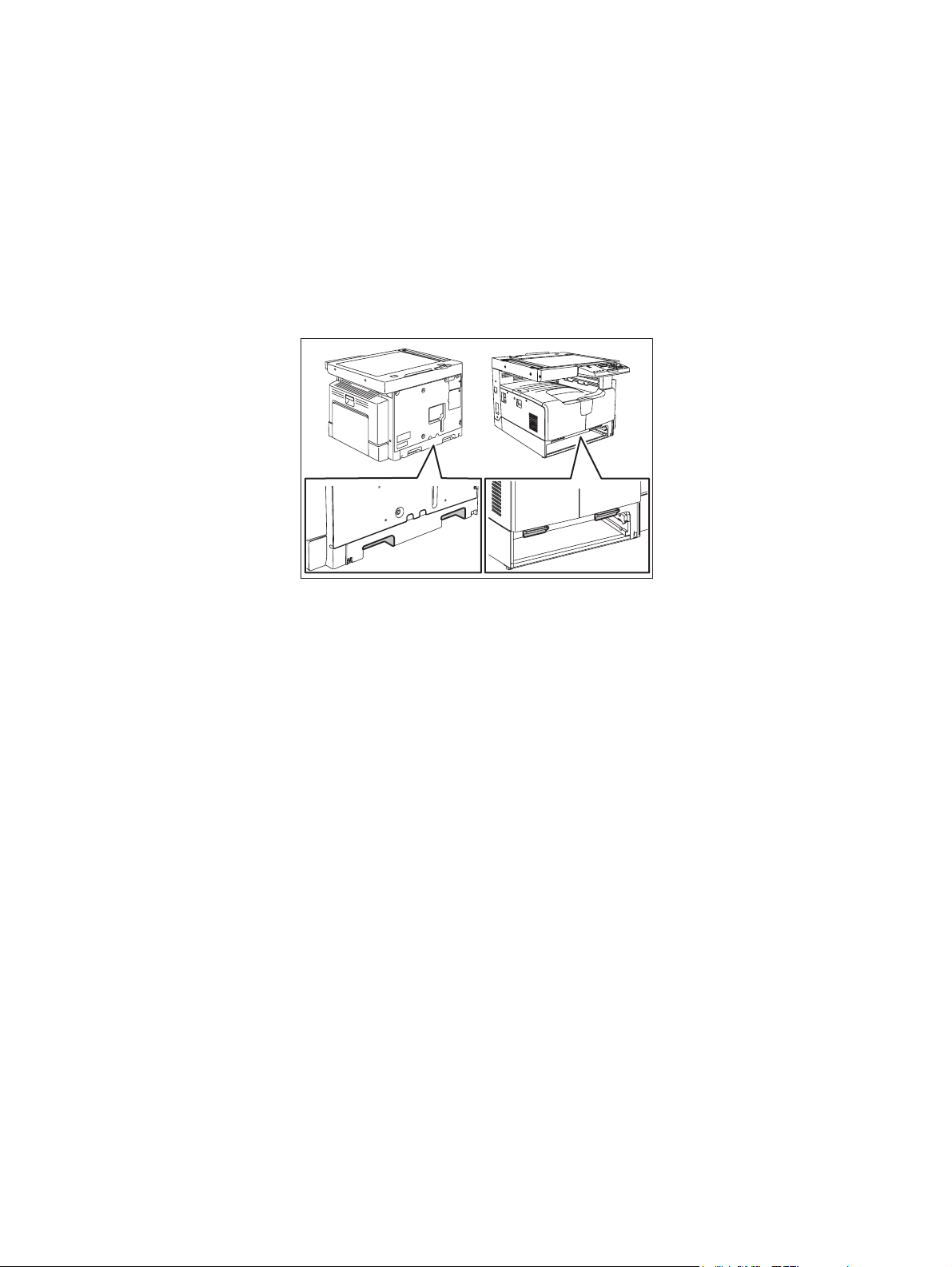
1) Transportation/Installation
- When transporting/installing the equipment, remove the drawer, employ two persons and be sure
to hold the positions as shown in the figure.
The equipment is quite heavy and weighs approximately 33 kg (72.75 lb), therefore pay full attention when handling it.
- Be sure not to hold the movable parts or units (e.g. the control panel, ADU or RADF) when trans-
porting the equipment.
- Be sure to use a dedicated outlet with AC 110 V / 13.2 A, 115 V or 127 V / 12 A, 220-240 V or 240
V / 8 A for its power source.
- The equipment must be grounded for safety.
- Select a suitable place for installation. Avoid excessive heat, high humidity, dust, vibration and
direct sunlight.
- Provide proper ventilation since the equipment emits a slight amount of ozone.
- To insure adequate working space for the copying operation, keep a minimum clearance of 80
cm (32”) on the left, 80 cm (32”) on the right and 10 cm (4”) on the rear.
- The equipment shall be installed near the socket outlet and shall be easily accessible.
- Be sure to fix and plug in the power cable securely after the installation so that no one trips over
it.
- When the equipment is used after the option is removed, be sure to install the parts or the covers
which have been taken off so that the inside of the equipment is not exposed.
2) General Precautions at Service
- Be sure to turn the power OFF and unplug the power cable during service (except for the service
should be done with the power turned ON).
- Unplug the power cable and clean the area around the prongs of the plug and socket outlet once
a year or more. A fire may occur when dust lies on this area.
- When the parts are disassembled, reassembly is the reverse of disassembly unless otherwise
noted in this manual or other related documents. Be careful not to install small parts such as
screws, washers, pins, E-rings, star washers in the wrong places.
- Basically, the equipment should not be operated with any parts removed or disassembled.
Page 4

- The PC board must be stored in an anti-electrostatic bag and handled carefully using a wristband
since the ICs on it may be damaged due to static electricity.
Caution: Before using the wristband, unplug the power cable of the equipment and
make sure that there are no charged objects which are not insulated in the
vicinity.
- Avoid expose to laser beam during service. This equipment uses a laser diode. Be sure not to
expose your eyes to the laser beam. Do not insert reflecting parts or tools such as a screwdriver
on the laser beam path. Remove all reflecting metals such as watches, rings, etc. before starting
service.
- Be sure not to touch high-temperature sections such as the exposure lamp, fuser unit, damp
heater and areas around them.
- Be sure not to touch high-voltage sections such as the chargers, developer, high-voltage trans-
former and power supply unit. Especially, the board of these components should not be touched
since the electric charge may remain in the capacitors, etc. on them even after the power is
turned OFF.
- Make sure that the equipment will not operate before touching potentially dangerous places (e.g.
rotating/operating sections such as gears, belts pulleys, fans and laser beam exit of the laser
optical unit).
- Be careful when removing the covers since there might be the parts with very sharp edges
underneath.
- When servicing the equipment with the power turned ON, be sure not to touch live sections and
rotating/operating sections. Avoid exposing your eyes to laser beam.
- Use designated jigs and tools.
- Use recommended measuring instruments or equivalents.
- Return the equipment to the original state and check the operation when the service is finished.
3) Important Service Parts for Safety
- The breaker, door switch, fuse, thermostat, thermofuse, thermistor, batteries, IC-RAMs including
lithium batteries, etc. are particularly important for safety. Be sure to handle/install them properly.
If these parts are short-circuited and their functions become ineffective, they may result in fatal
accidents such as burnout. Do not allow a short-circuit and/or do not use the parts not recommended by Toshiba TEC Corporation.
Page 5
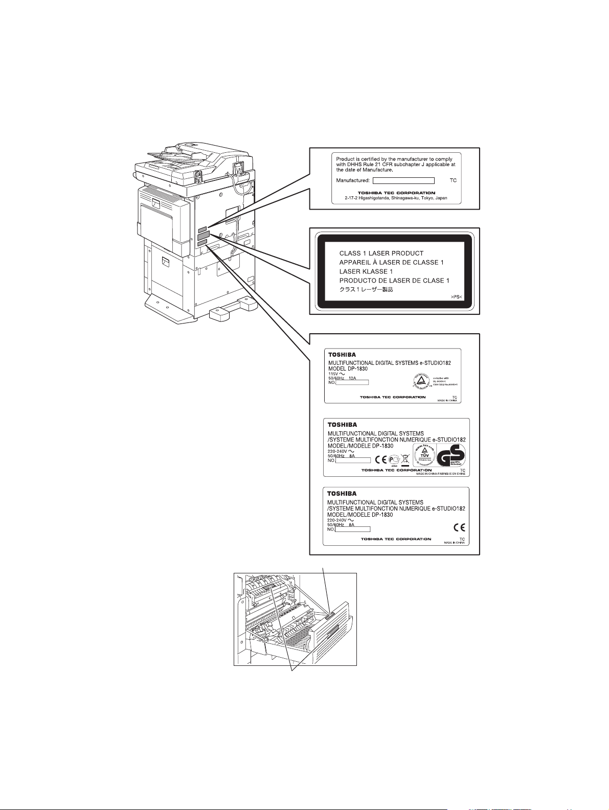
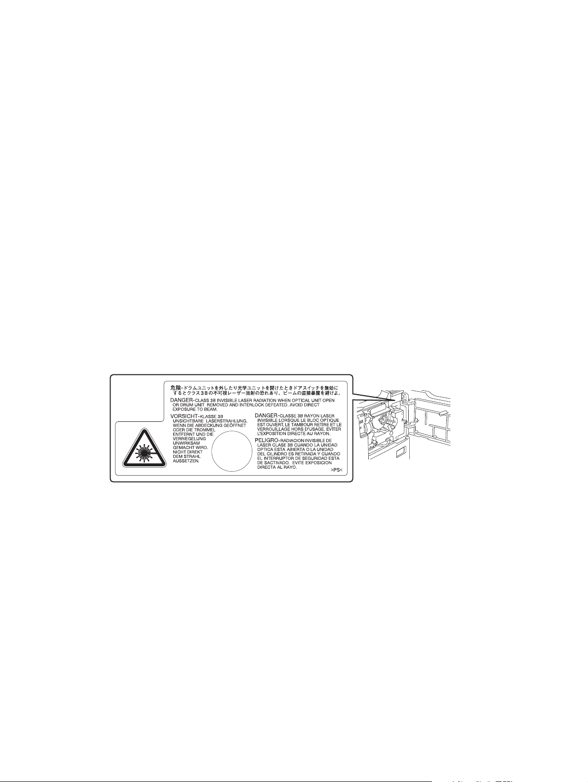
4) Cautionary Labels
- During servicing, be sure to check the rating plate and cautionary labels such as “Unplug the
power cable during service”, “CAUTION. HOT”, “CAUTION. HIGH VOLTAGE”, “CAUTION.
LASER BEAM”, etc. to see if there is any dirt on their surface and if they are properly stuck to the
equipment.
Certification label (For UC)
Explanatory label
Identification label
For UC
For EU
For others
Warning for high-temperature areas (ventilation holes
Warning for high-temperature areas (fuser unit
)
)
Page 6

5) Disposal of the Equipment, Supplies, Packing Materials, Used Batteries and IC-RAMs
- Regarding the recovery and disposal of the equipment, supplies, packing materials, used batter-
ies and IC-RAMs including lithium batteries, follow the relevant local regulations or rules.
Caution:
Dispose of used batteries and IC-RAMs including lithium batteries according to this manual.
Attention:
Se débarrasser de batteries et IC-RAMs usés y compris les batteries en lithium selon ce manuel.
Vorsicht:
Entsorgung der gebrauchten Batterien und IC-RAMs (inclusive der Lithium-Batterie) nach diesem Handbuch.
Page 7
ALLEGEMEINE SICHERHEITSMASSNAHMEN IN BEZUG
AUF DIE WARTUNG FÜR e-STUDIO182/212/242
Die Installation und die Wartung sind von einem qualifizierten ServiceTechniker durchzuführen.
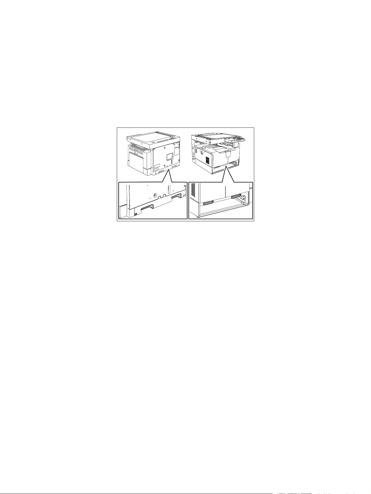
1) Transport/Installation
- Zum Transportieren/Installieren des Gerätes werden 2 Personen benötigt. Die Kassette zuerst
herausnehmen und nur an den in der Abbildung gezeigten Stellen tragen.
Das Gerät ist sehr schwer und wiegt etwa 33 kg; deshalb muss bei der Handhabung des Geräts
besonders aufgepasst werden.
- Beim Transportieren des Geräts nicht an den beweglichen Teilen oder Einheiten halten.
- Eine spezielle Steckdose mit Stromversorgung von AC 110 V / 13.2 A, 115 V oder 127 V / 12 A,
220-240 V / 8 A als Stromquelle verwenden.
- Das Gerät ist aus Sicherheitsgründen zu erden.
- Einen geeigneten Standort für die Installation wählen. Standorte mit zuviel Hitze, hoher Luft-
feuchtigkeit, Staub, Vibrieren und direkter Sonneneinstrahlung sind zu vermeiden.
- Für ausreichende Belüftung sorgen, da das Gerät etwas Ozon abgibt.
- Um einen optimalen Kopierbetrieb zu gewährleisten, muss ein Abstand von mindestens 80 cm
links, 80 cm rechts und 10 cm dahinter eingehalten werden.
- Das Gerät ist in der Nähe der Steckdose zu installieren; diese muss leicht zu erreichen sein.
- Nach der Installation muss das Netzkabel richtig hineingesteckt und befestigt werden, damit nie-
mand darüber stolpern kann.
2) Allgemeine Sicherheitsmassnahmen in bezug auf die Wartung
- Während der Wartung das Gerät ausschalten und das Netzkabel herausziehen (ausser Wartung,
die bei einem eingeschalteten Gerät, durchgeführt werden muss).
- Das Netzkabel herausziehen und den Bereich um die Steckerpole und die Steckdose die Umge-
bung in der Nähe von den Steckerzacken und der Steckdose wenigstens einmal im Jahr reinigen. Wenn Staub sich in dieser Gegend ansammelt, kann dies ein Feuer verursachen.
- Wenn die Teile auseinandergenommen werden, wenn nicht anders in diesem Handbuch usw
erklärt, ist das Zusammenbauen in umgekehrter Reihenfolge durchzuführen. Aufpassen, dass
kleine Teile wie Schrauben, Dichtungsringe, Bolzen, E-Ringe, Stern-Dichtungsringe, Kabelbäume nicht an den verkehrten Stellen eingebaut werden.
- Grundsätzlich darf das Gerät mit enfernten oder auseinandergenommenen Teilen nicht in
Betrieb genommen werden.
Page 8

- Das PC-Board muss in einer Anti-elektrostatischen Hülle gelagert werden. Nur Mit einer Man-
schette bei Betätigung eines Armbandes anfassen, sonst könnte es sein, dass die integrierten
Schaltkreise durch statische Elektrizität beschädigt werden.
Vorsicht: Vor Benutzung der Manschette der Betätigung des Armbandes, das Netzkabel
des Gerätes herausziehen und prüfen, dass es in der Nähe keine geladenen
Gegenstände, die nicht isoliert sind, gibt.
- Setzen Sie sich während der Wartungsarbeiten nicht dem Laserstrahl aus. Dieses Gerät ist mit
einer Laserdiode ausgestattet. Es ist unbedingt zu vermeiden, direkt in den Laserstrahl zu
blicken. Keine reflektierenden Teile oder Werkzeuge, wie z. B. Schraubendreher, in den Pfad des
Laserstrahls halten. Vor den Wartungsarbeiten sämtliche reflektierenden Metallgegenstände, wie
Uhren, Ringe usw., entfernen.
- Auf keinen Fall Hochtemperaturbereiche, wie die Belichtungslampe, die Fixiereinheit, die
Heizquelle und die umliegenden Bereiche, berühren.
- Auf keinen Fall Hochspannungsbereiche, wie die Ladeeinheiten, die Entwicklereinheit, den
Hochspannungstransformator, und das Netzgerät, berühren. Insbesondere sollten die Platinen
dieser Komponenten nicht berührt werden, da die Kondensatoren usw. auch nach dem Ausschalten des Geräts noch elektrisch geladen sein können.
- Vor dem Berühren potenziell gefährlicher Bereiche (z. B. drehbare oder betriebsrelevante Bere-
iche, wie Zahnräder, Riemen, Riemenscheiben, Lüfter und die Laseraustrittsöffnung der optischen Lasereinheit) sicherstellen, dass das Gerät sich nicht bedienen lässt.
- Beim Entfernen von Abdeckungen vorsichtig vorgehen, da sich darunter scharfkantige Kompo-
nenten befinden können.
- Bei Wartungsarbeiten am eingeschalteten Gerät dürfen keine unter Strom stehenden, drehbaren
oder betriebsrelevanten Bereiche berührt werden. Nicht direkt in den Laserstrahl blicken.
- Ausschließlich vorgesehene Werkzeuge und Hilfsmittel verwenden.
- Empfohlene oder gleichwertige Messgeräte verwenden.
- Nach Abschluss der Wartungsarbeiten das Gerät in den ursprünglichen Zustand zurück
versetzen und den einwandfreien Betrieb überprüfen.
3) Sicherheitsrelevante Wartungsteile
- Der Leistungsschutzschalter, der Türschalter, die Sicherung, der Thermostat, die Ther-
mosicherung, der Thermistor, die IC-RAMs einschließlich der Lithiumakkus usw. sind besonders
sicherheitsrelevant. Sie müssen unbedingt korrekt gehandhabt und installiert werden. Wenn
diese Teile kurzgeschlossen und funktionsunfähig werden, kann dies zu schwerwiegenden
Schäden, wie einem Abbrand, führen. Kurzschlüsse sind zu vermeiden, und es sind ausschließlich Teile zu verwenden, die von der Toshiba TEC Corporation empfohlen sind.
Page 9
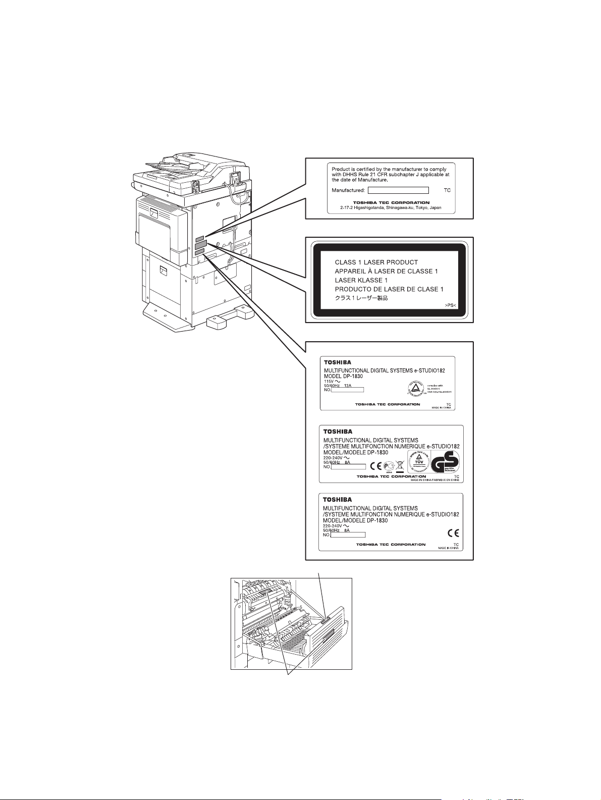
4) Warnetiketten
- Im Rahmen der Wartung unbedingt das Leistungsschild und die Etiketten mit Warnhinweisen
überprüfen [z. B. „Unplug the power cable during service“ („Netzkabel vor Beginn der Wartungsarbeiten abziehen“), „CAUTION. HOT“ („VORSICHT, HEISS“), „CAUTION. HIGH VOLTAGE“
(„VORSICHT, HOCHSPANNUNG“), „CAUTION. LASER BEAM“ („VORSICHT, LASER“) usw.],
um sicherzustellen, dass sie nicht verschmutzt sind und korrekt am Gerät angebracht sind.
Certification label (For UC)
Explanatory label
Identification label
For UC
For EU
For others
Warning for high-temperature areas (ventilation holes
Warning for high-temperature areas (fuser unit
)
)
Page 10

5) Entsorgung des Geräts, der Verbrauchs- und Verpackungsmaterialien, alter Akkus und IC-RAMs
- In Bezug auf die Entsorgung und Wiederverwertung des Geräts, der Verbrauchs- und Verpack-
ungsmaterialien, alter Akkus und IC-RAMs, einschließlich Lithiumakkus, sind die einschlägigen
nationalen oder regionalen Vorschriften zu befolgen.
Caution:
Dispose of used batteries and IC-RAMs including lithium batteries according to this manual.
Attention:
Se débarrasser de batteries et IC-RAMs usés y compris les batteries en lithium selon ce manuel.
Vorsicht:
Entsorgung der gebrauchten Batterien und IC-RAMs (inclusive der Lithium-Batterie) nach diesem Handbuch.
Page 11
• Laseremissionseinheit
Diese Einheit besteht aus der Laserdiode, dem Fokussierungsobjektiv, der Blende und dem Zylinderobjektiv.
- Laserdiode
Diese Laserdiode zeichnet sich durch eine geringe Regeldifferenz, eine kleine Laservariation und
einen niedrigen Schwellenstrom aus.
Die Blende der Laseremissionseinheit ist unter dem Fokussierobjektiv angeordnet, um die Form der
Laserstrahlen in der primären und sekundären Scanrichtung festzulegen.
Die Laserdiode gibt Laserstrahlen als Reaktion auf die Signale der Laseremissionssteuerung (ein/
aus) von der Lasertreiber-PC-Platine (LDR) aus. Die durch das Fokussierobjektiv geführten Laserstrahlen werden auf die Trommeloberfläche fokussiert.
- Vorsichtsmaßnahmen im Zusammenhang mit Lasern
Dieses Gerät enthält eine Laserdiode, die einen unsichtbaren Laserstrahl emittiert.
Da man diesen Laserstrahl nicht sehen kann, ist bei der Handhabung der Komponenten der optischen Lasereinheit, bei der Durchführung von Arbeiten und bei der Justierung des Laserstrahls
äußerste Vorsicht geboten. Arbeiten dürfen niemals anhand anderer als den vorgeschriebenen
Anleitungen durchgeführt werden; andernfalls kann es zu einer Schädigung Exposition durch Laserstrahlung kommen.
Die Lasereinheit ist vollständig mit einer Schutzabdeckung versiegelt. Solange ausschließlich die
Arbeitsschritte der vorgeschriebenen Anleitungen durchgeführt werden, tritt der Laserstrahl nicht
aus, und es besteht keine Gefahr, der Laserstrahlung ausgesetzt zu werden.
Das folgende Laser-Warnetikett ist an der Abdeckung vorne rechts angebracht.
• Warnhinweise:
- Setzen Sie sich während der Wartungsarbeiten nicht dem Laserstrahl aus.
Dieses Gerät ist mit einer Laserdiode ausgestattet. Es ist unbedingt zu vermeiden, direkt in den
Laserstrahl zu blicken. Keine reflektierenden Teile oder Werkzeuge, wie z. B. Schraubendreher,
in den Pfad des Laserstrahls halten. Vor den Wartungsarbeiten sämtliche reflektierenden Metallgegenstände, wie Uhren, Ringe usw., entfernen.
- Bei Wartungsarbeiten am eingeschalteten Gerät dürfen keine unter Strom stehenden, drehbaren
oder betriebsrelevanten Bereiche berührt werden. Nicht direkt in den Laserstrahl blicken.
- Im Rahmen der Wartung unbedingt das Leistungsschild und die Etiketten mit Warnhinweisen
überprüfen [z. B. „Unplug the power cable during service“ („Netzkabel vor Beginn der Wartungsarbeiten abziehen“), „CAUTION. HOT“ („VORSICHT, HEISS“), „CAUTION. HIGH VOLTAGE“
(„VORSICHT, HOCHSPANNUNG“), „CAUTION. LASER BEAM“ („VORSICHT, LASER“) usw.],
um sicherzustellen, dass sie nicht verschmutzt sind und korrekt am Gerät angebracht sind.
Page 12

Page 13

CONTENTS
1. SPECIFICATIONS / ACCESSORIES / OPTIONS / SUPPLIES ................................... 1-1
1.1 Specifications .................................................................................................................... 1-1
1.2 Accessories....................................................................................................................... 1-5
1.3 Options.............................................................................................................................. 1-6
1.4 Supplies ............................................................................................................................ 1-7
1.5 System List........................................................................................................................ 1-8
2. OUTLINE OF THE MACHINE ....................................................................................... 2-1
2.1 Sectional View................................................................................................................... 2-1
2.2 Electric Parts Layout ......................................................................................................... 2-4
2.3 Symbols and Functions of Various Components ............................................................ 2-11
2.4 General Description ........................................................................................................ 2-15
2.4.1 System block diagram ..................................................................................... 2-15
2.4.2 Construction of boards..................................................................................... 2-16
2.5 Disassembly and Replacement of Covers ...................................................................... 2-18
2.5.1 Front cover....................................................................................................... 2-18
2.5.2 Inner tray.......................................................................................................... 2-18
2.5.3 Left cover ......................................................................................................... 2-18
2.5.4 Tray rear cover ................................................................................................ 2-19
2.5.5 Front right cover............................................................................................... 2-19
2.5.6 Front upper cover ............................................................................................ 2-19
2.5.7 ADU cover ....................................................................................................... 2-20
2.5.8 Right front cover .............................................................................................. 2-20
2.5.9 Right rear cover ............................................................................................... 2-21
2.5.10 Rear cover ....................................................................................................... 2-21
2.6 Disassembly and Replacement of PC boards................................................................. 2-22
2.6.1 MAIN board (MAIN) ......................................................................................... 2-22
2.6.2 SRAM board (SRAM) ...................................................................................... 2-23
2.6.3 Fuse PC board (FUS) ...................................................................................... 2-23
2.6.4 Paper feed controller PC board (PFC)............................................................. 2-24
2.6.5 Switching regulator unit (PS) ........................................................................... 2-25
2.6.6 Switching regulator cooling fan (M6) ............................................................... 2-27
2.7 Removal and Installation of Options ............................................................................... 2-28
2.7.1 MR-2020 (Automatic Document Feeder (ADF))/
MR-3023 (Reversing Automatic Document Feeder (RADF)) .......................... 2-28
2.7.2 MY-1027 (Paper Feed Unit (PFU)) .................................................................. 2-30
2.7.3 KD-1022 (Paper Feed Pedestal (PFP)) ........................................................... 2-35
3. COPY PROCESS ..........................................................................................................3-1
3.1 General Description of Copying Process .......................................................................... 3-1
3.2 Details of Copying Process ............................................................................................... 3-2
3.3 Comparison with e-STUDIO230/280............................................................................... 3-13
4. GENERAL OPERATION............................................................................................... 4-1
4.1 Overview of Operation ...................................................................................................... 4-1
4.2 Description of Operation ................................................................................................... 4-2
4.2.1 Warming-up ....................................................................................................... 4-2
4.2.2 Ready state (ready for copying)......................................................................... 4-2
4.2.3 Drawer feed copying .......................................................................................... 4-3
4.2.4 Bypass feed copying.......................................................................................... 4-4
4.2.5 Interruption copying ........................................................................................... 4-4
4.3 Detection of Abnormality ................................................................................................... 4-5
4.3.1 Types of abnormality ......................................................................................... 4-5
4.3.2 Description of abnormality ................................................................................. 4-6
5. CONTROL PANEL........................................................................................................ 5-1
5.1 General Description .........................................................................................................5-1
© 2009 TOSHIBA TEC CORPORATION All rights reserved e-STUDIO182/212/242
1
CONTENTS
Page 14

5.2 Items Shown on the Display Panel ................................................................................... 5-2
5.2.1 Display ............................................................................................................... 5-2
5.2.2 Message ............................................................................................................ 5-3
5.3 Relation between Equipment State and Operation ........................................................... 5-4
5.4 Operation .......................................................................................................................... 5-5
5.4.1 Block diagram .................................................................................................... 5-5
5.4.2 LED display circuit ............................................................................................. 5-6
5.5 Disassembly and Replacement......................................................................................... 5-7
5.5.1 Control panel unit............................................................................................... 5-7
5.5.2 Control panel PC board (HPNL) ........................................................................ 5-7
5.5.3 LCD PC board (LCD) ......................................................................................... 5-8
6. SCANNER ..................................................................................................................... 6-1
6.1 General Description ..........................................................................................................6-1
6.2 Construction ...................................................................................................................... 6-2
6.3 Functions........................................................................................................................... 6-3
6.4 Description of Operation ................................................................................................... 6-5
6.4.1 Scanning operation............................................................................................ 6-5
6.4.2 Scan motor drive circuit ..................................................................................... 6-6
6.5 Contact Image Sensor Unit Control Circuit ....................................................................... 6-8
6.5.1 Exposure LED control circuit ............................................................................. 6-8
6.5.2 CCD control circuit............................................................................................. 6-9
6.6 Automatic Original Size Detection Circuit ....................................................................... 6-11
6.6.1 Principle of original size detection ................................................................... 6-11
6.6.2 Process of detection of original size ................................................................ 6-12
6.7 Disassembly and Replacement....................................................................................... 6-16
6.7.1 Original glass ................................................................................................... 6-16
6.7.2 Scanner top cover............................................................................................ 6-17
6.7.3 Automatic original detection sensor (APS sensor) .......................................... 6-18
6.7.4 Scan motor (M1) .............................................................................................. 6-18
6.7.5 CIS home position sensor (S1)........................................................................ 6-20
6.7.6 Platen sensor (S2) ........................................................................................... 6-20
6.7.7 CIS unit (CIS)................................................................................................... 6-21
6.7.8 CIS case .......................................................................................................... 6-23
6.7.9 CIS unit drive belt-1 ........................................................................................ 6-24
6.7.10 CIS unit drive belt-2 ......................................................................................... 6-25
7. LASER OPTICAL UNIT ................................................................................................ 7-1
7.1 General Description ..........................................................................................................7-1
7.2 Structure............................................................................................................................ 7-2
7.3 Laser Diode Control Circuit ............................................................................................... 7-5
7.4 Polygonal Motor Control Circuit ........................................................................................ 7-6
7.5 Disassembly and Replacement......................................................................................... 7-7
7.5.1 Laser optical unit................................................................................................ 7-7
8. DRIVE UNIT .................................................................................................................. 8-1
8.1 General Description ..........................................................................................................8-1
8.2 Configuration..................................................................................................................... 8-2
8.3 Functions .......................................................................................................................... 8-3
8.4 Main Motor Control Circuit ................................................................................................ 8-4
8.5 Disassembly and Replacement......................................................................................... 8-6
8.5.1 Main motor (M3) ................................................................................................ 8-6
8.5.2 Toner motor (M2)............................................................................................... 8-6
8.5.3 Main motor drive unit ......................................................................................... 8-7
9. PAPER FEEDING SYSTEM.......................................................................................... 9-1
9.1 General Description ..........................................................................................................9-1
9.2 Configuration..................................................................................................................... 9-2
9.3 Functions........................................................................................................................... 9-3
9.4 Operation .......................................................................................................................... 9-5
e-STUDIO182/212/242 © 2009 TOSHIBA TEC CORPORATION All rights reserved
CONTENTS
2
Page 15

9.4.1 Drawer ............................................................................................................... 9-5
9.4.2 Bypass tray ........................................................................................................ 9-7
9.4.3 General operation .............................................................................................. 9-9
9.5 Disassembly and Replacement....................................................................................... 9-10
9.5.1 Bypass unit ...................................................................................................... 9-10
9.5.2 Bypass tray ...................................................................................................... 9-11
9.5.3 Bypass separation pad ................................................................................... 9-11
9.5.4 Bypass roller unit ............................................................................................. 9-12
9.5.5 Bypass pickup roller ........................................................................................ 9-14
9.5.6 Bypass feed roller ........................................................................................... 9-14
9.5.7 Bypass paper sensor (S8) ............................................................................... 9-14
9.5.8 Bypass pickup solenoid (SOL2)....................................................................... 9-15
9.5.9 Bypass pickup clutch / Bypass feed clutch ...................................................... 9-16
9.5.10 Damp heater unit (DH3) / Dummy plate .......................................................... 9-18
9.5.11 Paper empty sensor (S7)................................................................................. 9-18
9.5.12 Pickup roller .................................................................................................... 9-19
9.5.13 Registration clutch (CLT1) ............................................................................... 9-20
9.5.14 Pickup solenoid (SOL1) ................................................................................... 9-20
9.5.15 Drawer pickup clutch ....................................................................................... 9-21
9.5.16 Registration roller (rubber)............................................................................... 9-22
9.5.17 Registration roller (metal) ................................................................................ 9-23
9.5.18 Feed gear unit.................................................................................................. 9-24
9.5.19 Drawer detection switch (SW5) ....................................................................... 9-24
9.5.20 Registration sensor (S4) .................................................................................. 9-25
10. DRUM RELATED SECTION....................................................................................... 10-1
10.1 General Description ........................................................................................................ 10-1
10.2 Configuration................................................................................................................... 10-2
10.3 Functions......................................................................................................................... 10-3
10.4 High-Voltage Output Control Circuit................................................................................ 10-5
10.4.1 General description.......................................................................................... 10-5
10.4.2 Description of Operation .................................................................................. 10-6
10.5 Drum Temperature Detection Circuit .............................................................................. 10-7
10.5.1 General description.......................................................................................... 10-7
10.5.2 Circuit configuration ......................................................................................... 10-7
10.6 Temperature/Humidity Detection Circuit ......................................................................... 10-8
10.6.1 General Description ......................................................................................... 10-8
10.6.2 Circuit configuration ......................................................................................... 10-8
10.7 Disassembly and Replacement....................................................................................... 10-9
10.7.1 Process unit ..................................................................................................... 10-9
10.7.2 Drum cleaner unit .......................................................................................... 10-11
10.7.3 Discharge LED (ERS).................................................................................... 10-12
10.7.4 Main charger.................................................................................................. 10-13
10.7.5 Main charger grid .......................................................................................... 10-13
10.7.6 Main charger cleaner ..................................................................................... 10-14
10.7.7 Needle electrode ........................................................................................... 10-14
10.7.8 Drum ............................................................................................................. 10-15
10.7.9 Drum cleaning blade ..................................................................................... 10-15
10.7.10 Drum separation finger ................................................................................. 10-15
10.7.11 Recovery blade ............................................................................................. 10-16
10.7.12 Transfer/Separation charger .......................................................................... 10-16
10.7.13 Charger wire ................................................................................................. 10-17
10.7.14 Transfer unit................................................................................................... 10-18
10.7.15 Ozone filter ................................................................................................... 10-19
10.7.16 Exhaust fan (M5) ........................................................................................... 10-20
10.7.17 Temperature/humidity sensor (S3) ................................................................ 10-21
10.7.18 Toner cartridge interface PC board (CTIF) .................................................... 10-22
© 2009 TOSHIBA TEC CORPORATION All rights reserved e-STUDIO182/212/242
3
CONTENTS
Page 16

11. DEVELOPMENT SYSTEM..........................................................................................11-1
11.1 General Description ........................................................................................................ 11-1
11.2 Construction.................................................................................................................... 11-2
11.3 Functions......................................................................................................................... 11-3
11.3.1 Function of each unit ....................................................................................... 11-3
11.3.2 Functions of the toner cartridge PC board (CTRG) ......................................... 11-4
11.3.3 Recovered toner supply mechanism ............................................................... 11-6
11.4 Toner Motor Control Circuit............................................................................................. 11-7
11.5 Auto-Toner Circuit........................................................................................................... 11-8
11.5.1 General description.......................................................................................... 11-8
11.5.2 Function of auto-toner sensor.......................................................................... 11-9
11.6 Disassembly and Replacement..................................................................................... 11-11
11.6.1 Developer unit................................................................................................ 11-11
11.6.2 Developer material ........................................................................................ 11-12
11.6.3 Filling developer unit with developer material................................................ 11-13
11.6.4 Auto-toner sensor (S6) .................................................................................. 11-14
11.6.5 Drum thermistor (THMS4) ............................................................................. 11-14
11.6.6 Guide roller / Developer sleeve ..................................................................... 11-14
11.6.7 Mixer .............................................................................................................. 11-18
11.6.8 Replacement of Oil Seal ................................................................................ 11-20
12. FUSER / EXIT UNIT ....................................................................................................12-1
12.1 General Description ........................................................................................................ 12-1
12.2 Configurations................................................................................................................. 12-2
12.3 Functions......................................................................................................................... 12-3
12.4 Operation ........................................................................................................................ 12-5
12.5 Fuser Unit Control Circuit................................................................................................ 12-6
12.5.1 Configuration ................................................................................................... 12-6
12.5.2 Temperature detection section ........................................................................ 12-7
12.6 Disassembly and Replacement..................................................................................... 12-12
12.6.1 Fuser / Exit unit.............................................................................................. 12-14
12.6.2 Pressure roller unit / Fuser roller unit............................................................. 12-14
12.6.3 Exit roller........................................................................................................ 12-15
12.6.4 Exit sensor (S5) ............................................................................................ 12-16
12.6.5 Separation finger ......................................................................................... 12-18
12.6.6 Center heater lamp / Side heater lamp (LAMP1/LAMP2) .............................. 12-19
12.6.7 Fuser roller .................................................................................................... 12-20
12.6.8 Pressure roller .............................................................................................. 12-20
12.6.9 Center thermistor / Side thermistor / Edge thermistor
(THMS1/THMS2/THMS3)............................................................................. 12-22
12.6.10 Fuser thermostat (THMO1)............................................................................ 12-22
12.6.11 Exit motor (M7): Option.................................................................................. 12-23
13. AUTOMATIC DUPLEXING UNIT (ADU) (OPTION: MD-0103) .................................. 13-1
13.1 General Description ........................................................................................................ 13-1
13.1.1 Specifications of MD-0103............................................................................... 13-2
13.2 Construction.................................................................................................................... 13-3
13.3 Functions......................................................................................................................... 13-4
13.4 Drive of ADU ................................................................................................................... 13-5
13.5 Description of Operation ................................................................................................ 13-6
13.6 Disassembly and Replacement..................................................................................... 13-11
13.6.1 Automatic Duplexing Unit (ADU) ................................................................... 13-11
13.6.2 ADU driving PC board (ADU) ........................................................................ 13-12
13.6.3 ADU motor (M8)............................................................................................. 13-12
13.6.4 Upper transport roller..................................................................................... 13-13
13.6.5 Lower transport roller..................................................................................... 13-13
13.6.6 Paper guide ................................................................................................... 13-14
e-STUDIO182/212/242 © 2009 TOSHIBA TEC CORPORATION All rights reserved
CONTENTS
4
Page 17

14. POWER SUPPLY UNIT .............................................................................................. 14-1
14.1 Construction.................................................................................................................... 14-1
14.2 Operation of DC Output Circuit ....................................................................................... 14-2
14.3 Output Channel............................................................................................................... 14-3
14.4 Fuse ................................................................................................................................ 14-4
14.5 Configuration of Power Supply Unit ................................................................................ 14-5
14.6 AC Wire Harness ............................................................................................................ 14-6
15. EXTERNAL COUNTERS ............................................................................................15-1
15.1 Outline............................................................................................................................. 15-1
15.2 Signal .............................................................................................................................. 15-1
15.2.1 Pin Layout........................................................................................................ 15-1
15.2.2 Details of the signals........................................................................................ 15-2
15.3 Notices ............................................................................................................................ 15-3
15.3.1 Setting code..................................................................................................... 15-3
15.3.2 Setting value change and restrictions when using the totalizer
(DocuLyzerNW) .............................................................................................. 15-3
15.3.3 Setting value change and restrictions when using the coin controller ............. 15-3
15.3.4 Simultaneous Installation of External Counters ............................................... 15-3
16. PC BOARDS ............................................................................................................... 16-1
© 2009 TOSHIBA TEC CORPORATION All rights reserved e-STUDIO182/212/242
5
CONTENTS
Page 18

e-STUDIO182/212/242 © 2009 TOSHIBA TEC CORPORATION All rights reserved
CONTENTS
6
Page 19
1. SPECIFICATIONS / ACCESSORIES / OPTIONS / SUPPLIES
1.1 Specifications
When the value is different among e-STUDIO182, 212 and 242, the value for
e-STUDIO212 is shown by [ ] and the value for e-STUDIO242 is shown by { }.
Copy process Indirect electrophotographic process (dry)
Type Desktop type
Original table Fixed type (the left rear corner used as guide to place originals)
Accepted originals Sheet, book and 3-dimensional object. The automatic document feeder
(ADF) and reversing automatic document feeder (RADF), only accepts paper
which are not pasted or stapled. (Single-sided originals: 50 to 127 g/m
34 lb. Bond) Carbon paper are not acceptable either.
Maximum size: A3/LD
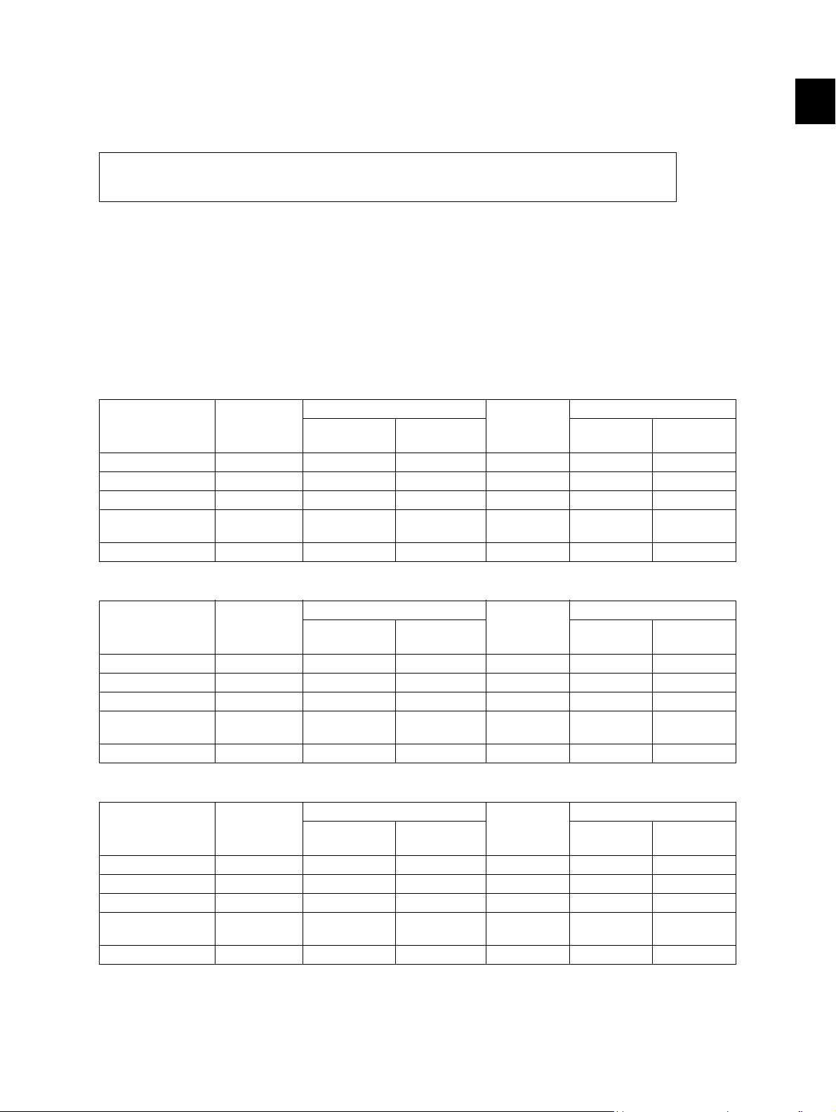
Copy speed (Copies/min.)
e-STUDIO182
Bypass feed
Paper size Drawer
A4, B5, LT 18 16 11 16 16 16
A5-R, ST-R - 16 11 - 16 16
A4-R, B5-R, LT-R 15.5 15.5 11 15.5 15.5 15.5
B4, LG, FOLIO,
COMPUTER
A3 , L D 11 11 11 11 11 11
13 13 11 13 13 13
Size
specified
Size not
specified
PFU
Upper
drawer
PFP
2
Lower
drawer
1
/13 to
e-STUDIO212
Bypass feed
Paper size Drawer
A4, B5, LT 21 20 20 20 20 20
A5-R, ST-R - - 20 - 20 20
A4-R, B5-R, LT-R 15.5 15.5 15.5 15.5 15.5 15.5
B4, LG, FOLIO,
COMPUTER
A3 , L D 11 11 11 11 11 11
13 13 13 13 13 13
Size
specified
Size not
specified
PFU
Upper
drawer
PFP
Lower
drawer
e-STUDIO242
Bypass feed
Paper size Drawer
A4, B5, LT 24 23 23 23 23 23
A5-R, ST-R - - 23 - 23 23
A4-R, B5-R, LT-R 17.5 17.5 17.5 17.5 17.5 17.5
B4, LG, FOLIO,
COMPUTER
A3, LD 12.5 12.5 12.5 12.5 12.5 12.5
15 15 15 15 15 15
Size
specified
Size not
specified
PFU
Upper
drawer
PFP
Lower
drawer
* “–” means “Not acceptable”.
* The copy speed in the above table are available when originals are manually placed for single side,
multiple copying.
© 2009 TOSHIBA TEC CORPORATION All rights reserved e-STUDIO182/212/242
1 - 1
SPECIFICATIONS / ACCESSORIES / OPTIONS / SUPPLIES
Page 20

* When the ADF and RADF are used, the copy speed of 16[20] {23} sheets per minute is only
available under the following conditions:
• Original/Mode: Single side original/A4/LT size. APS/automatic density are not selected.
• Number of sheets: 16[20] {23}
• Reproduction ratio: 100%
Copy speed for thick paper (Copies/min.)
e-STUDIO182/212/242
Thick 1 (81 g/m
2
to 105 g/m2, 21.3 lb. Bond to 28 lb. Bond): Bypass feed on a sheet by sheet baisis
only
Thick 2 (106 g/m
2
to 163 g/m2, 28 lb. Bond to 90 lb. Index): Bypass feed on a sheet by sheet baisis only
Copy paper
Drawer PFU PFP ADU Bypass copy Remarks
Size A3, A4, A4-R, B4, B5, B5-R,
Weight
Special
paper
A5-R(Only for PFP), LD, LG, LT, LT-R,
ST-R(Only for PFP), FOLIO, COMPUTER,
13"LG, 8K, 16K, 16K-R
2
64 to 80 g/m
– Tracing paper, labels, OHP film
, 17 lb. Bond to 21.3 lb. Bond 50 to 163 g/m
First copy time ..................... e-STUDIO182/212
Approx. 7.6 sec. (A4, 100%, original placed manually)
Approx. 7.7 sec. (LT, 100%, original placed manually)
e-STUDIO242
Approx. 7.5 sec. (A4/LT, 100%, original placed manually)
A3 to A5-R, LD to ST-R,
FOLIO, COMPUTER, 13"LG,
8.5" x 8.5", 8K, 16K, 16K-R
(Non-standard or userspecified sizes can be set.)
2
(Single paper feeding)
64 to 80 g/m
(Continuous feeding)
(thickness: 80 µm or thicker),
2
These special papers
recommended by
Tos h i b a Te c
Warming-up time.................. Approx. 25 sec. (temperature: 20°C)
Multiple copying ................... Up to 999 copies; Key in set numbers
Reproduction ratio ............... Actual ratio: 100±0.5%
Zooming: 25 to 200% in increments of 1%
Resolution/Gradation ........... Scanning: 600 dpi x 600 dpi
Printing: Equivalent to 2400 dpi x 600 dpi
Gradation: 256 steps
Eliminated portion ................ Leading edges: 3.0±2.0 mm, Side/trailing edges: 2.0±2.0 mm (copy)
Leading / trailing edges: 5.0±2.0 mm, Side edges: 5.0±2.0 mm (print)
e-STUDIO182/212/242 © 2009 TOSHIBA TEC CORPORATION All rights reserved
SPECIFICATIONS / ACCESSORIES / OPTIONS / SUPPLIES
1 - 2
Page 21

Paper feeding ......................... Standard drawer:
1 drawer (stack height 28 mm, equivalent to 250 sheets; 64 to 80 g/m
(17 to 22 lb. Bond))
Bypass feeding:
Stack height 11.8 mm: equivalent to 100 sheets; 64 to 80 g/m
22 lb. Bond)
Paper Feed Unit (PFU):
Option (One drawer: stack height 28 mm, equivalent to 250 sheets; 64
to 80 g/m
2
(17 to 22 lb. Bond))
Paper Feed Pedestal (PFP):
Option (One drawer or two: stack height 60.5 mm, equivalent to 550
sheets; 64 to 80 g/m
2
(17 to 22 lb. Bond))
Capacity of originals in the ADF/RADF (Option)
.................................................. A3 to A5-R, LD to ST-R:
100 sheets / 80 g/m
2
(Stack height 16 mm or less)
Automatic duplexing unit (ADU: Option)
.................................................. Stackless, Switchback type
Toner supply ........................... Automatic toner density detection/supply
Toner cartridge replacing method (There is a recovered toner supply
mechanism.)
2
(17 to
2
1
Density control ..................... Automatic density mode and manual density mode selectable in 7
steps
Weight.................................. Approx. 32.0 kg ( 70.55 lb.) (for NAD and MJD)
Approx. 33.2 kg ( 73.19 lb.) (for CND)
Approx. 33.0 kg ( 72.75 lb.) (for others)
Power requirements...AC 110 V / 13.2 A, 115 V or 127 V / 12 A
220-240 V or 240 V / 8 A (50/60 Hz)
* The acceptable value of each voltage is ±10%.
Power consumption ... 1.5 kW or less (100 V series)
1.6 kW or less (200 V series)
* The electric power is supplied to the ADF/RADF, PFU, PFP and ADU through the equipment.
Total counter ..............Electronical counter
© 2009 TOSHIBA TEC CORPORATION All rights reserved e-STUDIO182/212/242
1 - 3
SPECIFICATIONS / ACCESSORIES / OPTIONS / SUPPLIES
Page 22
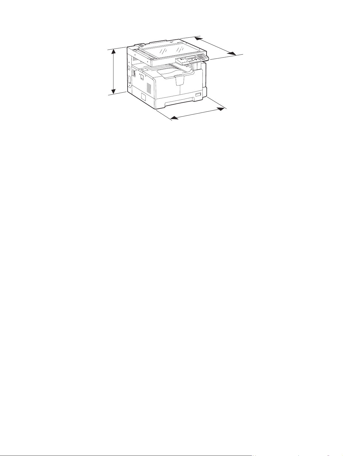
Dimensions of the equipment .................. W 600 x D 658.6 x H 462.5 (mm): See the figure below
D
H
W
Fig. 1-1
e-STUDIO182/212/242 © 2009 TOSHIBA TEC CORPORATION All rights reserved
SPECIFICATIONS / ACCESSORIES / OPTIONS / SUPPLIES
1 - 4
Page 23

1.2 Accessories
Unpacking/setup instruction 1 set
Operator’s manual 1 pc.
Operator’s manual pocket 1 pc. (for NAD)
Power cable 1 pc.
CD-ROM 2 pcs.
Rubber cap 6 pcs. (for MJD, ASD, ASU and SAD)
2 pcs. (for NAD, CND, AUD, TWD, KRD and ARD)
Transfer charger wire cleaner
(installed inside of the transfer cover)
Drum (installed inside of the equipment) 1 pc.
Developer material 1 pc.
Nozzle 1 pc. (for NAD)
Toner cartridge 1 pc.
Warranty sheet 1 pc. (for NAD and CND)
Setup report 1 set (for NAD, MJD and CND)
Customer satisfaction card 1 pc. (for MJD)
Packing list 1 pc. (for CND)
Customer survey sheet 1 pc. (for CND)
Certificate of conformance 1 pc. (for CND)
1 pc.
* Machine version
NAD: North America
ASD: Hong Kong / Latin America
AUD: Australia
MJD: Europe
ASU: Asia / Saudi Arabia
SAD: Saudi Arabia
ARD: Latin America
CND: China
TWD: Taiwan
KRD: Korea
JPD: Japan
1
© 2009 TOSHIBA TEC CORPORATION All rights reserved e-STUDIO182/212/242
1 - 5
SPECIFICATIONS / ACCESSORIES / OPTIONS / SUPPLIES
Page 24

1.3 Options
Platen Cover KA-1650PC/PCC
Automatic Document Feeder (ADF) MR-2020/C
Reversing Automatic Document Feeder (RADF) MR-3023/C
Paper Feed Unit (PFU) MY-1027/C
Paper Feed Pedestal (PFP) KD-1022/C
Paper Feed Controller (PFC) GH-1060/C
Drawer Module MY-1028/C
Automatic Duplexing Unit (ADU) MD-0103/C
Fax Kit GD-1221NA/EU/AU/TW/CN/KR
External Keyboard GJ-1060/C/EU/KR/TW
Network Printer Kit GA-1191/C/KR/TW
Scanner Upgrade Kit GA-1201/C/KR/TW
Operator’s manual pocket KK-1660/C
Damp Heater MF-1640U/E
Harness Kit GQ-1130
Desk MH-1640
Notes:
• When the paper feed pedestal (KD-1022) or automatic duplexing unit (MD-0103) is installed,
the paper feed controller (GH-1060) is also required to be installed.
• The external keyboard (GJ-1060) is necessary for the installation of the fax kit (GD-1221) and
the scanner upgrade kit (GA-1201).
e-STUDIO182/212/242 © 2009 TOSHIBA TEC CORPORATION All rights reserved
SPECIFICATIONS / ACCESSORIES / OPTIONS / SUPPLIES
1 - 6
Page 25

1.4 Supplies
Drum OD-1600 (except for China)
OD-2320 (for China)
Toner cartridge PS-ZT1810 (1) (for North America)
PS-ZT1810A (1) (for Central and South America)
PS-ZT1810D (1) (for Asia)
PS-ZT1810D5k (1) (for Asia)
PS-ZT1810C (1) (for China)
PS-ZT1810C10k (1) (for China)
PS-ZT1810C5k (1) (for China)
PS-ZT1810T (1) (for Taiwan)
PS-ZT1810T5k (1) (for Taiwan)
PS-ZT1810E (1) (for Europe)
PS-ZT1810E5K (1) (for Europe)
Developer material D-2320 (except for China)
D-2320C (for China)
1
© 2009 TOSHIBA TEC CORPORATION All rights reserved e-STUDIO182/212/242
1 - 7
SPECIFICATIONS / ACCESSORIES / OPTIONS / SUPPLIES
Page 26
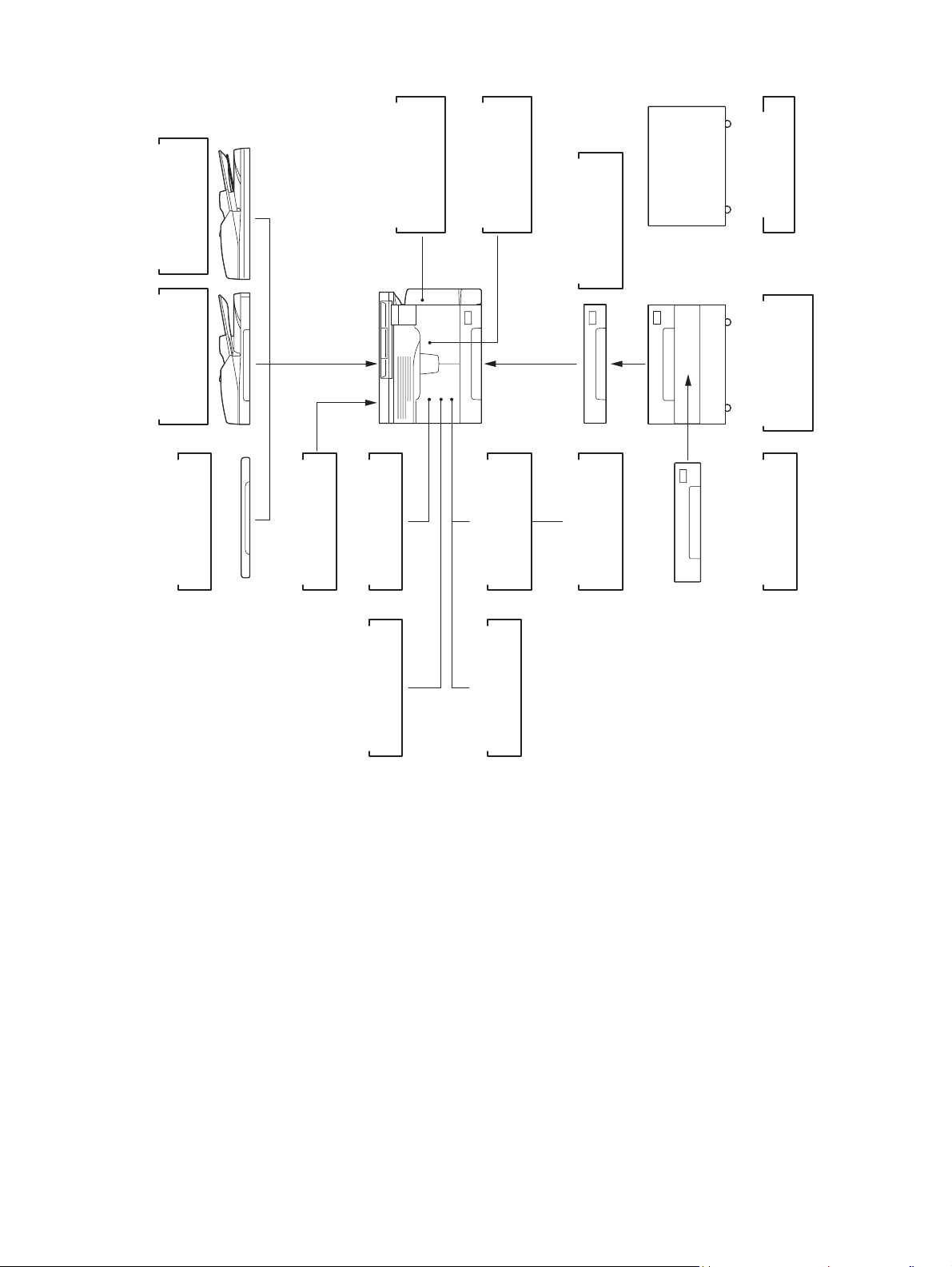
1.5 System List
)
RADF
(
MR-3023
Document Feeder
Reversing Automatic
)
ADF
(
MR-2020
Automatic
Document Feeder
KA-1650PC
Platen Cover
Automatic
Duplexing Unit
GJ-1060
MF-1640
Damp Heater
External Keyboard
)
ADU
(
MD-0103
)
PFC
(
GH-1060
Controller
Paper Feed
Network
GA-1191
Printer Kit
)
PFU
(
MY-1027
Paper Feed Unit
Scanner
GA-1201
Upgrade Kit
Desk
MH-1640
)
PFP
(
Pedestal
Paper Feed
KD-1022
MY-1028
Drawer Module
GQ-1130
Harness Kit
Fig. 1-2
Fax Kit
GD-1221
e-STUDIO182/212/242 © 2009 TOSHIBA TEC CORPORATION All rights reserved
SPECIFICATIONS / ACCESSORIES / OPTIONS / SUPPLIES
1 - 8
Page 27
2. OUTLINE OF THE MACHINE
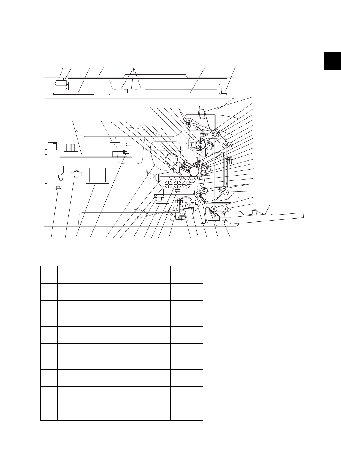
2.1 Sectional View
1. Front side
A2 A1A3
K4
A4
K2
A7
J7J6
I5
I9
F1F2F3
H3
H2
J4J5 J8
A5
A6
K5
J3
J9
J1
J2
L3
L1
I7
H4
H5
H1
G2
G1
G3
L3
I1
C5
L2
E2
E1
2
E5
K3
A1 Original glass
A2 ADF original glass
A3 Contact image sensor unit (CIS)
A4 Scanner damp heater (Left side) DH1
A5 Scanner damp heater (Right side) DH2
A6 Scanner damp heater thermostat THMO2
A7 Automatic original detection sensor S9-S13
B1 Laser optical unit
B2 Polygonal motor M4
C1 Pickup roller
C2 Separation claw
C3 Paper empty sensor S7
C4 Registration sensor S4
C5 Registration roller
E1 Bypass pickup roller
E2 Bypass feed roller
E3 Bypass separation pad
E4 Bypass paper sensor S8
B1B2 C1 C2C3
F4
I11
I4 I3I2I6I8
I10K1
Fig. 2-1
C4
E3
E4
© 2009 TOSHIBA TEC CORPORATION All rights reserved e-STUDIO182/212/242
2 - 1
OUTLINE OF THE MACHINE
Page 28

E5 Bypass tray
F1 Needle electrode
F2 Main charger
F3 Main charger grid
F4 Toner cartridge
G1 Transfer charger wire
G2 Separation charger wire
G3 Transfer guide roller
H1 Drum
H2 Discharge LED
H3 Drum cleaning blade
H4 Recovery blade
H5 Drum separation finger
I1 Developer sleeve (Magnetic roller)
I2 Mixer-1
I3 Mixer-2
I4 Mixer-3
I5 Doctor blade
I6 Auto-toner sensor S6
I7 Toner recovery auger
I8 Toner recycle auger
I9 Drum thermistor THMS4
I10 Drum damp heater DH3
I11 Drum damp heater thermostat THMO3
J1 Fuser roller
J2 Pressure roller
J3 Fuser roller separation finger
J4 Center heater lamp LAMP1
J5 Side heater lamp LAMP2
J6 Center/Side/Edge thermistor THMS1/2/3
J7 Fuser thermostat THMO1
J8 Exit roller
J9 Exit sensor S5
K1 Front cover opening/closing switch SW4
K2 Front cover opening/closing interlock switch SW3
K3 Temperature/humidity sensor S3
K4 Switching regulator
K5 ADU cover opening/closing interlock switch SW2
L1 ADU upper transport roller
L2 ADU lower transport roller
L3 ADU paper guide
e-STUDIO182/212/242 © 2009 TOSHIBA TEC CORPORATION All rights reserved
OUTLINE OF THE MACHINE
2 - 2
Page 29
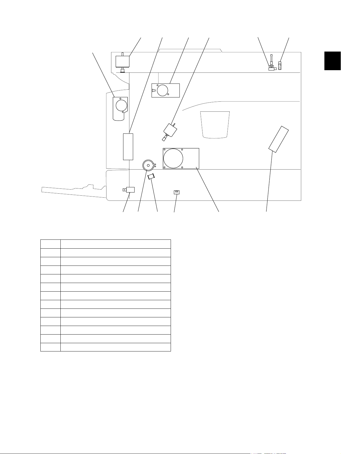
2. Rear side
M8
M1 M2
M5
M7
S2 S1
2
M1 Scan motor
M2 Toner motor
M3 Main motor
M5 Exhaust fan
M6 Switching regulator cooling fan
M7 Exit motor (Option)
M8 ADU motor (Option)
S1 CIS home position sensor
S2 Platen sensor
SW5 Drawer detection switch
CLT1 Registration clutch
SOL1 Pickup solenoid
SOL2 Bypass pickup solenoid
CLT1
SW5
Fig. 2-2
M3SOL1SOL2 M6
© 2009 TOSHIBA TEC CORPORATION All rights reserved e-STUDIO182/212/242
2 - 3
OUTLINE OF THE MACHINE
Page 30
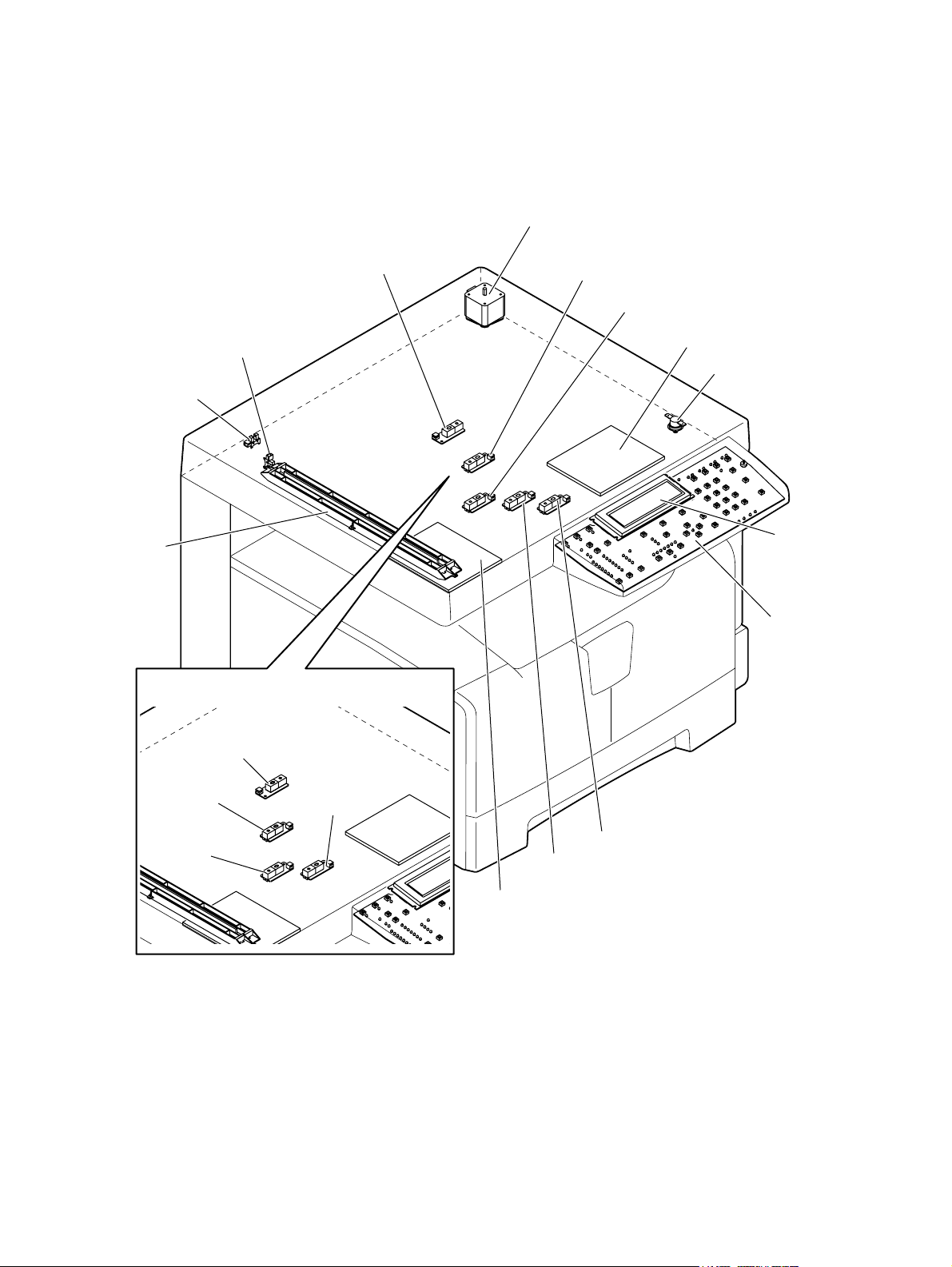
2.2 Electric Parts Layout
[A] Scanner, control panel
M1
S1
S2
CIS
LT series models
S13
S12
S11
DH2
THMO2
LCD
HPNL
S13
S12
S11
S10
S10
S9
DH1
Fig. 2-3
e-STUDIO182/212/242 © 2009 TOSHIBA TEC CORPORATION All rights reserved
OUTLINE OF THE MACHINE
2 - 4
Page 31

[B] Power supply section, switches
PS
2
SW3
SW2
SW4
SW1
S3
Fig. 2-4
© 2009 TOSHIBA TEC CORPORATION All rights reserved e-STUDIO182/212/242
2 - 5
M6
OUTLINE OF THE MACHINE
Page 32

[C] Laser optical unit, fuser unit, toner cartridge section
CTRG
CTIF
M2
M7
S5
LAMP1
LAMP2
SNS
THMO1
THMS1
LDR
THMS2
M4
Fig. 2-5
e-STUDIO182/212/242 © 2009 TOSHIBA TEC CORPORATION All rights reserved
OUTLINE OF THE MACHINE
2 - 6
THMS3
Page 33

[D] Developer unit section
S6
2
ERS
M5
THMS4
FUS
THMO3
DH3
Fig. 2-6
© 2009 TOSHIBA TEC CORPORATION All rights reserved e-STUDIO182/212/242
2 - 7
OUTLINE OF THE MACHINE
Page 34

[E] Driving section
SRAM
MAIN
CLT1
M3
PFC
SOL1
Fig. 2-7
e-STUDIO182/212/242 © 2009 TOSHIBA TEC CORPORATION All rights reserved
OUTLINE OF THE MACHINE
2 - 8
S4
Page 35

[F] Drawer section
2
SW5
S7
Fig. 2-8
© 2009 TOSHIBA TEC CORPORATION All rights reserved e-STUDIO182/212/242
2 - 9
OUTLINE OF THE MACHINE
Page 36

[G] Bypass unit, automatic duplexing unit
M8
ADU
S8
SOL2
Fig. 2-9
e-STUDIO182/212/242 © 2009 TOSHIBA TEC CORPORATION All rights reserved
OUTLINE OF THE MACHINE
2 - 10
Page 37

2.3 Symbols and Functions of Various Components
The column "P-I" shows the page and item number in the parts list.
1. Motors
Symbol Name Function Remarks P-I
M1 SCAN-MOT
Scan motor
M2 TNR-MOT
Toner motor
M3 MAIN-MOT
Main motor
M4 M/DC-POL
Polygonal motor
M5 EXT-FAN-MOT
Exhaust fan
M6 PS-FAN-MOT
Switching regulator cooling fan
M7 EXIT-MOT
Exit motor
M8 ADU-MOT
ADU motor
Driving the CIS Fig. 2-3 10-1
Supplying the toner Fig. 2-5 12-15
Driving the drum, developer unit,
registration roller, Pickup roller, feed
roller, cleaner unit
Driving the polygonal mirror Fig. 2-5 5-13
Exhausting ozone and cooling down
the equipment inside
Cooling down the switching regulator Fig. 2-4 5-11
Driving the fuser unit and exit roller
*Option
Driving the automatic duplexing unit
*Option
Fig. 2-7 12-2
Fig. 2-6 11-23
Fig. 2-5 MD-0103
Fig. 2-9 MD-0103
2
2-2
1-23
© 2009 TOSHIBA TEC CORPORATION All rights reserved e-STUDIO182/212/242
2 - 11
OUTLINE OF THE MACHINE
Page 38

2. Sensors and switches
Symbol Name Function Remarks P-I
S1 HOME-SNR
CIS home position sensor
S2 PLTN-SNR
Platen sensor
S3 TEMP/HUMI-SNR
Temperature/humidity sensor
S4 RGST-SNR
Registration sensor
S5 EXIT-SNR
Exit sensor
S6 ATTNR-SNR
Auto-toner sensor
S7 EMP-SNR
Paper empty sensor
S8 SFB-SNR
Bypass paper sensor
S9-13 APS 1-3, APS-C, APS-R
Automatic original detection sensor
SW1 MAIN-SW
Main switch
SW2 ADU-COV-INTLCK-SW
ADU cover opening/closing interlock
switch
Detecting CIS home position Fig. 2-3 10-106
Detecting the opening/closing of platen
Fig. 2-3 9-101
cover or RADF
Detecting the temperature and humidity
Fig. 2-4 5-16
inside the equipment
Detecting the transporting paper at the
Fig. 2-7 15-107
registration roller section
Detecting the transporting paper at the
Fig. 2-5 24-8
exit section
Detecting the density of toner in the
Fig. 2-6 21-46
developer unit
Detecting presence/absence of paper
Fig. 2-8 15-107
in the drawer
Detecting presence/absence of paper
Fig. 2-9 13-101
on the bypass tray
Detecting original size
* S9: only for A4 series models
Fig. 2-3 9-9,
9-19
Turning ON/OFF of the equipment Fig. 2-4 5-4
Controlling cutoff and supply of the 24V
Fig. 2-4 6-8
voltage by opening/closing of the ADU
cover
SW3 FRNT-COV-INTLCK-SW
Front cover opening/closing interlock
switch
SW4 FRNT-COV-SW
Front cover opening/closing switch
SW5 CST-SW
Drawer detection switch
Controlling cutoff and supply of the 24V
voltage by opening/closing of the front
cover
Detecting the opening/closing of the
front cover
Detecting presence/absence of the
drawer
Fig. 2-4 1-5
Fig. 2-4 1-101
Fig. 2-8 16-110
3. Electromagnetic clutch
Symbol Name Function Remarks P-I
CLT1 RGST-CLT
Driving the registration roller Fig. 2-7 16-21
Registration clutch
4. Solenoids
Symbol Name Function Remarks P-I
SOL1 CST-SOL
Pickup solenoid
SOL2 SFB-SOL
Bypass pickup solenoid
Controlling the power transmission of
the feed roller
Controlling the power transmission of
the bypass pickup roller
Fig. 2-7 16-9
Fig. 2-9 14-15
e-STUDIO182/212/242 © 2009 TOSHIBA TEC CORPORATION All rights reserved
OUTLINE OF THE MACHINE
2 - 12
Page 39

5. PC boards
Symbol Name Function Remarks P-I
MAIN PWA-F-MAIN
Main PC board (MAIN board)
SRAM PWA-F-SRAM
SRAM PC board (SRAM board)
LDR PWA-F-LDR
Laser driving PC board (LDR board)
SNS PWA-F-SNS
H-sync signal detection PC board
(SNS board)
HPNL PWA-F-HPNL
Control panel PC board
(HPNL board)
CTIF PWA-F-CTIF
Toner cartridge interface PC board
(CTIF board)
CTRG PWA-F-CTRG
Toner cartridge PC board
(CTRG board)
FUS PWA-F-FUS
Fuse PC board (FUS board)
PFC PWA-F-PFC
Paper feed controller PC board
(PFC board)
Controlling the whole system and
Fig. 2-7 7-1
image processing
Storing the setting information of the
Fig. 2-7 7-33
equipment
Driving the laser diode Fig. 2-5 5-13
Detecting the laser beam position Fig. 2-5 5-13
Detecting the button entry and
Fig. 2-3 4-20
controlling LED and LCD on the control
panel
Interface for detecting the toner
Fig. 2-5 7-30
cartridge
(Detecting the CTRG board)
Storing the status of the toner cartridge Fig. 2-5 103-3
Supplying power to each damp heater
Fig. 2-6 7-12
* Optional for NAD/MJD/CND model,
standard for other models
Controlling the automatic duplexing unit
Fig. 2-7 7-35
and paper feed pedestal
*Option
2
ADU PWA-F-ADU
ADU driving PC board (ADU board)
Controlling the automatic duplexing unit
*Option
Fig. 2-9 MD-0103
6. Lamps and heaters
Symbol Name Function Remarks P-I
LAMP1 CNTR-LAMP
Center heater lamp
LAMP2 SIDE-LAMP
Side heater lamp
ERS LP-ERS
Discharge LED
DH1 SCN-DH-L
Scanner damp heater (Left)
DH2 SCN-DH-R
Scanner damp heater (Right)
DH3 DRM-DH
Drum damp heater
Heating the center section of the fuser
roller
Heating the section of both sides of the
fuser roller
Removing the residual charge from the
drum surface
Preventing condensation in the
scanner unit
* Optional for NAD/MJD/CND model,
standard for other models
Preventing condensation in the
scanner unit
* Optional for NAD/MJD/CND model,
standard for other models
Preventing condensation of the drum
* Optional for NAD/MJD/CND model,
standard for other models
Fig. 2-5 23-12
Fig. 2-5 23-13
Fig. 2-6 20-13
Fig. 2-3 9-17
Fig. 2-3 9-18
Fig. 2-6 8-6
1-13
© 2009 TOSHIBA TEC CORPORATION All rights reserved e-STUDIO182/212/242
2 - 13
OUTLINE OF THE MACHINE
Page 40

7. Thermistors and thermostats
Symbol Name Function Remarks P-I
THMS1 THMS-C-HTR
Center thermistor
Detecting the surface temperature at
the center of the fuser roller (for
Fig. 2-5 23-6
controlling the center heater lamp)
THMS2 THMS-S-HTR
Side thermistor
Detecting the surface temperature at
the rear side of the fuser roller (for
Fig. 2-5 23-6
controlling the side heater lamp)
THMS3 THMS-EDG-HTR
Edge thermistor
Detecting the surface temperature at
the edge of the rear side of the fuser
Fig. 2-5 23-6
roller (for preventing overheating)
THMS4 THMS-DRM
Drum thermistor
THMO1 THERMO-FSR
Detecting the temperature on the drum
Fig. 2-6 21-49
surface
Preventing overheating in the fuser unit Fig. 2-5 23-5
Fuser thermostat
THMO2 THERMO-SCN-DH
Scanner damp heater thermostat
Preventing overheating in the scanner
damp heater
Fig. 2-3 9-20
* Optional for NAD/MJD/CND model,
standard for other models
THMO3 THERMO-DRM-DH
Drum damp heater thermostat
Preventing overheating in the drum
damp heater
Fig. 2-6 8-7
* Optional for NAD/MJD/CND model,
standard for other models
8. Others
Symbol Name Function Remarks P-I
CIS CIS
Contact image sensor unit
PS PS-ACC
Switching regulator
LCD LCD
LCD panel
Reading originals Fig. 2-3 9-8
• Generating DC voltage and
Fig. 2-4 5-2
supplying it to each section of the
equipment
• Generating high voltage and
supplying it to the main charger,
developer, transfer and separation
units
• Supplying AC power to the heater
lamp
Displaying each information Fig. 2-3 4-19
e-STUDIO182/212/242 © 2009 TOSHIBA TEC CORPORATION All rights reserved
OUTLINE OF THE MACHINE
2 - 14
Page 41

2.4 General Description
2.4.1 System block diagram
)
device
10BASE-T/
USB connector
(
LAN connector
(
100BASE-TX)USB connector
Network printer kit
)
device
(
USB connector
)
16 bit
(
SDRAM bus
)
host
(
Scanner upgrade kit
16
SDRAM
SDRAM
16 16
SDRAM
64 MB
32 MB
16 MB
Battery
FAX board
NCU board
MODEM
8
SRAM
Battery
SRAM board
Control panel
8
128 kB
RTC
Download JIG
TELBOOK board
External keyboard
16
16
16
CPU bus (16 bit)
512 kB
Flash ROM
8
4 MB
Flash ROM
2
Clutches
Solenoids
Bypass unit
I/O
PFU
Motors
Sensors
Switches
8
)
ASIC
I/O port
(
Copy key card /
Coin controller
: Option
8
MAIN board
ADF/RADF
AFE
CIS
Driver
M
Scan motor
)
High voltage
DC
(
DC
LVPS
HVPS
Power supply unit
AC
SoC
(System controller)
D/A
converter
Laser optical unit
Fig. 2-10
ASIC
Laser diode
LDR board
Laser beam sensor
SNS board
A/D
converter
Drum thermistor
Auto-toner sensor
Developer unit
sensor
Thermistors
Temperature/humidity
Fuser unit
ADU
PFC
PFP
© 2009 TOSHIBA TEC CORPORATION All rights reserved e-STUDIO182/212/242
OUTLINE OF THE MACHINE
2 - 15
Page 42

2.4.2 Construction of boards
[ 1 ] Construction diagram of boards
This system consists of the following including the MAIN board as a main board.
Control panel
HPNL
Toner cartridge
CTRGCTIF
Laser optical unit
LDR
SNS
Automatic duplexing unit
ADU
AC input
Scanner unit
CIS
FUS
PS-ACC
Main switch Cover opening/closing
SRAM
HVPS
LVPS
interlock switches
:
DC power supply line
:
AC power supply line
:
Signal line
MAIN
PFC
Fig. 2-11
[ 2 ] Function of each board
• MAIN board:
This is the board taking the leading part in all systems. It consists of the SoC, ASIC, memory
(SDRAM, Flash ROM), etc. In the SoC (System control), which is a core of this MAIN board, the
functions of the CPU, image processing, page memory control, CODEC, external interface (USB)
control, etc. are embedded and performed by one chip.
Based on the data input from the control panel, the SoC controls each system, such as the ASIC,
each memory, CIS unit and laser optical unit, and thus permitting the scanning of originals and the
printing of data.
• SRAM board:
This is the board on which the SRAM for storing the user's setting information and counter value and
its backup function are mounted. When the MAIN board is replaced, attaching this board to the new
MAIN board can assume the data of the previous equipment.
• HPNL board:
This is the board on which each button switch and LEDs on the control panel, and the LCD control
circuit are mounted.
• CTRG board:
This is the board on which the IC chip for storing information about the toner cartridge (number of
prints, identification data, etc.) is mounted.
• CTIF board:
This is the interface board with the CTRG board in the toner cartridge. Information written in the IC
chip on the CTRG board is read into the SoC on the MAIN board through this board.
• LDR board:
This is the board on which the laser diode and the ASIC are mounted. The laser is emitted based on
the image data signal output from the SoC on the MAIN board.
e-STUDIO182/212/242 © 2009 TOSHIBA TEC CORPORATION All rights reserved
OUTLINE OF THE MACHINE
2 - 16
Page 43

• SNS board:
This is the board on which the light sensor for detecting the radiating position of the laser is
mounted. It outputs the H-sync signal to the SoC on the MAIN board.
• PS-ACC:
This is the unit to generate each DC (high/low) voltage, which is used in the equipment, from the
external AC electric power input. This is then provided to each electric part.
• FUS board:
This is the board to provide AC electric power for driving the damp heater.
* Optional for NAD/MJD/CND model, standard for other models.
•CIS:
This is the unit witch performs optical-to-electrical conversion to convert the light reflected by the
original into the electrical signals. It consists of a light source (LEDs), optical system, CCD sensor,
etc.
• PFC board:
This is the board to control the optional Automatic Duplexing Unit (ADU) and optional Paper Feed
Pedestal (PFP).
• ADU board:
This is the board to control the optional Automatic Duplexing Unit (ADU). It detects paper feeding
with a sensor mounted on the ADU board.
2
© 2009 TOSHIBA TEC CORPORATION All rights reserved e-STUDIO182/212/242
2 - 17
OUTLINE OF THE MACHINE
Page 44

2.5 Disassembly and Replacement of Covers
2.5.1 Front cover
(1) Open the front cover.
(2) Release the upper hinge.
(3) Take off the front cover while lifting it up.
2.5.2 Inner tray
(1) Remove 2 screws and take off the Inner tray.
Front cover
Fig. 2-12
Inner tray
Fig. 2-13
2.5.3 Left cover
(1) Take off the Inner tray.
P.2-18 "2.5.2 Inner tray"
(2) Remove 4 screws and take off the left cover.
Left cover
Fig. 2-14
e-STUDIO182/212/242 © 2009 TOSHIBA TEC CORPORATION All rights reserved
OUTLINE OF THE MACHINE
2 - 18
Page 45

2.5.4 Tray rear cover
(1) Take off the left cover.
P.2-18 "2.5.3 Left cover"
(2) Take off the tray rear cover.
2.5.5 Front right cover
(1) Take off the front cover.
P.2-18 "2.5.1 Front cover"
(2) Pull out the toner cartridge.
(3) Open the ADU cover.
(4) Remove 2 screws and take off the front right
cover.
2
Tray rear cover
Fig. 2-15
Front right cover
2.5.6 Front upper cover
(1) Remove 1 screw and take off the front upper
cover.
Fig. 2-16
Front upper cover
Fig. 2-17
© 2009 TOSHIBA TEC CORPORATION All rights reserved e-STUDIO182/212/242
2 - 19
OUTLINE OF THE MACHINE
Page 46

2.5.7 ADU cover
(1) Open the bypass tray.
(2) Open the ADU cover.
(3) Open the transfer unit and release the ADU
stopper on the front side.
(4) Remove 1 screw and take off the ADU
stopper on the rear side.
Note:
Be careful not to fall off the ADU cover when
the screws are removed from the ADU
stopper.
(5) Take off the ADU cover while sliding it toward
the right.
ADU stopperADU stopper
Fig. 2-18
ADU cover
2.5.8 Right front cover
(1) Take off the front cover.
P.2-18 "2.5.1 Front cover"
(2) Open the ADU cover.
(3) Pull out the drawer.
(4) Remove 2 screws and take off the right front
cover.
Fig. 2-19
Right front cover
Fig. 2-20
e-STUDIO182/212/242 © 2009 TOSHIBA TEC CORPORATION All rights reserved
OUTLINE OF THE MACHINE
2 - 20
Page 47

2.5.9 Right rear cover
(1) Open the ADU cover.
(2) Remove 1 screw and take off the ADU
stopper on the rear side.
(3) Take off the 2 screw and take off the right
rear cover.
2.5.10 Rear cover
(1) Remove 5 screws and take off the rear
cover.
2
Right rear cover
Fig. 2-21
Fig. 2-22
Rear cover
© 2009 TOSHIBA TEC CORPORATION All rights reserved e-STUDIO182/212/242
2 - 21
OUTLINE OF THE MACHINE
Page 48

2.6 Disassembly and Replacement of PC boards
Notes:
• When the PC board/HDD is replaced, refer to each CAUTIONS of TROUBLESHOOTHING in
the SERVICE HANDBOOK.
• If the PC board has to be replaced due to an operational defect, this may have been caused
by a contact failure of the connector. Before replacing the board, disconnect and then
reconnect the connector to check if this action eliminates the operational defect.
2.6.1 MAIN board (MAIN)
(1) Take off the rear cover.
P.2-21 "2.5.10 Rear cover"
(2) Disconnect 16 connectors.
Note:
Connect the flat harness to the MAIN board
with its electrode side down. An error “CA2”
will be displayed if the connection is
incorrect.
(3) Remove 6 screws and take off the MAIN
board.
Notes:
1. When replacing the MAIN board, also
attach the SRAM board to the new MAIN
board from the old MAIN board.
2. Be sure to perform “08-389” after the
SRAM board has been replaced.
3. Be sure to perform "05-310" with the
platen cover or the ADF/RADF closed
after replacing the MAIN board.
Fig. 2-23
MAIN board
Fig. 2-24
e-STUDIO182/212/242 © 2009 TOSHIBA TEC CORPORATION All rights reserved
OUTLINE OF THE MACHINE
2 - 22
Page 49

2.6.2 SRAM board (SRAM)
(1) Take off the rear cover.
P.2-21 "2.5.10 Rear cover"
(2) Release 1 lock support and take off the
SRAM board.
Notes:
1. Be sure to perform “08-388” after the
SRAM board has been replaced.
2. Perform "05-310" with the platen cover
and the ADF/RADF closed after replacing
the SRAM board.
3. Make sure that the direction of the battery
on the SRAM board is correct when
replacing it.
2
SRAM board
Fig. 2-25
SRAM board
Battery
Fig. 2-26
2.6.3 Fuse PC board (FUS)
Note:
This fuse PC board is copacked with the damp heater unit. (The damp heater unit is optional for
NAD, CND and MJD.)
(1) Take off the rear cover.
P.2-21 "2.5.10 Rear cover"
(2) Remove 2 screws and take off the cover.
Cover
Fig. 2-27
© 2009 TOSHIBA TEC CORPORATION All rights reserved e-STUDIO182/212/242
2 - 23
OUTLINE OF THE MACHINE
Page 50

(3) Disconnect 2 connectors, remove 1 screw,
and then take off the fuse PC board by lifting
it up.
Fuse PC board
2.6.4 Paper feed controller PC board (PFC)
Note:
This paper feed controller PC board is optional for NAD, CND and MJD.
Connector
Fig. 2-28
(1) Take off the rear cover.
P.2-21 "2.5.10 Rear cover"
(2) Disconnect 2 connectors, remove 4 screws,
and then take off the paper feed controller
PC board and mylar sheet.
Notes:
• If the ADU (optional) is installed,
disconnect 2 connectors of the ADU with
other connectors at the same time before
taking off the paper feed controller PC
board.
• If the PFP (optional) is installed,
disconnect 2 connectors of the PFP with
other connectors at the same time before
taking off the paper feed controller PC
board.
Connector (ADU
Connector (PFP
Connector
)
)
Mylar
Paper feed controller
PC board
Fig. 2-29
e-STUDIO182/212/242 © 2009 TOSHIBA TEC CORPORATION All rights reserved
OUTLINE OF THE MACHINE
2 - 24
Page 51

2.6.5 Switching regulator unit (PS)
(1) Take off the left cover.
P.2-18 "2.5.3 Left cover"
(2) Disconnect 15 connectors.
Note:
The number of connectors to be
disconnected is 15 when the following
options are installed.
A: Paper Feed Controller (GH-1060)
B: Fax Kit (GD-1220/1221)
A
B
Fig. 2-30
2
Note:
Connect the connectors to the correct faston
terminals on the switching regulator board.
Connector Harness
F. Red - Black-thick
E. Blue - White-thick
D. White - Black-thin
C. White - Red-thin
B. White - Red-thick
A. White - White-thick
(3) Remove 2 screws, slide the switching
regulator unit with the whole case slightly to
the front, and then lift it up to take it off.
F
E
D
C
B
A
Fig. 2-31
Switching regulator unit
Fig. 2-32
© 2009 TOSHIBA TEC CORPORATION All rights reserved e-STUDIO182/212/242
2 - 25
OUTLINE OF THE MACHINE
Page 52

(4) Disconnect 7 connectors.
(5) Remove 1 screw and 1 ground wire.
Connector Connector
Fig. 2-33
Note:
Make sure that the position is correct when
inserting the connector.
(6) Remove 8 screws, release 1 locking support,
and take off the switching regulator board.
Green/Yellow
Black
White
White Gray
2
4
1
3
Black Brown
Locking support
Fig. 2-34
Switching regulator board
Fig. 2-35
e-STUDIO182/212/242 © 2009 TOSHIBA TEC CORPORATION All rights reserved
OUTLINE OF THE MACHINE
2 - 26
Page 53

2.6.6 Switching regulator cooling fan (M6)
(1) Take off the left cover.
P.2-18 "2.5.3 Left cover"
(2) Disconnect 1 connector and take off the
switching regulator cooling fan while sliding it
upward.
Switching regulator cooling fan
2
Connector
Fig. 2-36
© 2009 TOSHIBA TEC CORPORATION All rights reserved e-STUDIO182/212/242
2 - 27
OUTLINE OF THE MACHINE
Page 54

2.7 Removal and Installation of Options
2.7.1 MR-2020 (Automatic Document Feeder (ADF))/MR-3023 (Reversing Automatic Document Feeder (RADF))
(1) Turn the power OFF and unplug the power
cable.
(2) Remove 1 screw and take off the connector
cover.
Fig. 2-37
(3) Remove the ground wire.
(4) Disconnect the connector.
Fig. 2-38
Fig. 2-39
e-STUDIO182/212/242 © 2009 TOSHIBA TEC CORPORATION All rights reserved
OUTLINE OF THE MACHINE
2 - 28
Page 55

(5) Remove 1 screw on the rear right side.
(6) Remove the cover on the rear right side.
2
Fig. 2-40
(7) Remove 1 screw and 1 washer on the rear
left side.
(8) Open the ADF/RADF.
Fig. 2-41
Fig. 2-42
Fig. 2-43
© 2009 TOSHIBA TEC CORPORATION All rights reserved e-STUDIO182/212/242
2 - 29
OUTLINE OF THE MACHINE
Page 56

(9) Remove 2 screws on the front side.
(10) Slide the ADF/RADF backward and take off
by lifting it up.
Fig. 2-44
2.7.2 MY-1027 (Paper Feed Unit (PFU))
[G-1] When PFP is not installed
(1) Turn the power OFF and unplug the power
cable.
(2) Remove 1 screw and take off the PFU
connector cover.
Fig. 2-45
Fig. 2-46
e-STUDIO182/212/242 © 2009 TOSHIBA TEC CORPORATION All rights reserved
OUTLINE OF THE MACHINE
2 - 30
Page 57

(3) Remove the ground wire.
(4) Disconnect the connector.
2
Fig. 2-47
(5) Install the PFU connector cover.
(6) Take off the rear cover.
P.2-21 "2.5.10 Rear cover"
(7) Disconnect 1 connector (optional damp
heater). Release the harness from the
harness clamp.
Fig. 2-48
Fig. 2-49
Fig. 2-50
© 2009 TOSHIBA TEC CORPORATION All rights reserved e-STUDIO182/212/242
2 - 31
OUTLINE OF THE MACHINE
Page 58

(8) Take off the drawer of the equipment and
PFU drawer.
(9) Remove 1 screw and take off 1 fixing bracket
on the front left side.
Fig. 2-51
(10) Remove 1 screw and take off 1 fixing bracket
on the front right side.
(11) Remove 1 screw and take off 1 fixing bracket
on the rear left side.
Fig. 2-52
Fig. 2-53
Fig. 2-54
e-STUDIO182/212/242 © 2009 TOSHIBA TEC CORPORATION All rights reserved
OUTLINE OF THE MACHINE
2 - 32
Page 59

(12) Remove 1 screw and take off 1 fixing bracket
on the rear right side.
(13) Lift up the equipment and take off the PFU.
2
Fig. 2-55
[G-2] When PFP is installed
(1) Take off the rear cover.
P.2-21 "2.5.10 Rear cover"
(2) Remove 1 ground wire and 2 connectors.
Fig. 2-56
Fig. 2-57
© 2009 TOSHIBA TEC CORPORATION All rights reserved e-STUDIO182/212/242
2 - 33
OUTLINE OF THE MACHINE
Page 60

(3) Take off the equipment from the PFU.
P.2-30 "[G-1] When PFP is not installed"
(4) Take off the PFP drawer.
(5) Remove 1 screw and take off 1 fixing bracket
on the front left side.
Fig. 2-58
(6) Remove 1 screw and take off 1 fixing bracket
on the front right side.
(7) Remove 1 screw and take off 1 fixing bracket
on the rear left side.
Fig. 2-59
Fig. 2-60
Fig. 2-61
e-STUDIO182/212/242 © 2009 TOSHIBA TEC CORPORATION All rights reserved
OUTLINE OF THE MACHINE
2 - 34
Page 61

(8) Remove 1 screw and take off 1 fixing bracket
on the rear right side.
(9) Take off the PFU while lifting it up.
2
Fig. 2-62
2.7.3 KD-1022 (Paper Feed Pedestal (PFP))
(1) Take off the equipment and the PFU. Then
take off the PFP.
P.2-33 "[G-2] When PFP is installed"
Fig. 2-63
Fig. 2-64
© 2009 TOSHIBA TEC CORPORATION All rights reserved e-STUDIO182/212/242
2 - 35
OUTLINE OF THE MACHINE
Page 62

e-STUDIO182/212/242 © 2009 TOSHIBA TEC CORPORATION All rights reserved
OUTLINE OF THE MACHINE
2 - 36
Page 63

3. COPY PROCESS
3.1 General Description of Copying Process
Paper exit
(2)
Data reading(scanning)
CIS
600 dpi,7084 pixel
Image processing
(1)
Charging
e-STUDIO167/207:-448V
e-STUDIO237 :-454V
(grid voltage)
(3)
Data writing
Semiconductive laser
Pw=4.0 nJ/mm
(10)
Discharging
Discharge LED (red)
Wavelength 660nm x10pcs
2
(4)
Development
Magnetic roller
Bias -340VDC+AC
Fig. 3-1
(9)
Cleaning
Blade method
Toner
Carrier
(8)
Fusing
Lamp heating method
564W x2
(7)
H -107 µADC
C -107 µADC
L -70 µADC
(6)
H 340 µADC
C 369 µADC
L 282 µADC
(5)
DC +565V
Bypass feeding
(
100 sheets
Drawer feeding
(
250 sheets
PFU
(
250 sheets
3
Separation
Transfer
Transfer bias
)
)
)
(1) Charging: Applies negative charge on the
surface of the photoconductive drum.
(2) Data reading: The images on the original
are converted into electrical signals.
(3) Data writing: The electrical signals are
converted into light signal (laser emission)
which exposes the surface of the
photoconductive drum.
(4) Development: Negatively-charged toner
adheres to the photoconductive drum and
forms visible image.
(5) Transfer bias: Improves transfer efficiency.
(6) Transfer: Transfers the visible toner image
on the photoconductive drum onto paper.
(7) Separation: Separates paper with the toner
image from the photoconductive drum.
(8) Fusing: Fuses the toner image onto the
paper by applying heat and pressure.
(9) Cleaning: Scrapes off the residual toner
from the drum.
(10) Discharging: Eliminates the residual
negative charge from the surface of the
photoconductive drum.
© 2009 TOSHIBA TEC CORPORATION All rights reserved e-STUDIO182/212/242
3 - 1
COPY PROCESS
Page 64

3.2 Details of Copying Process
1. Photoconductive drum
The photoconductive drum consists of two layers.The outer layer is a photoconductive layer made of
an organic photoconductive carrier (OPC), and the inner layer is an aluminum conductive base in a
cylindrical form. The photoconductor has the following property: when it is exposed to light, the
electrical resistance it possesses increases or decreases according to the strength of the light.
Example:
- Strong light
Resistance is decreased (works as a conductor.)
- Weak light
Resistance is increased (works as an insulator.)
Photoconductive layer
Base
Structure of the photoconductive drum
(
Example of OPC
Fig. 3-2
[Formation of electrostatic latent image]
In the processes of charging, data reading, data writing, discharging described later, negative
potential of the areas on the drum corresponding to black areas of the original are eliminated, while
the areas on the drum corresponding to white areas retains the negative charge.
As this image on the drum formed by the negative potential is not visible, it is called an “electrostatic
latent image.”
)
)
Time (t
)
0
V
(
Black area of original
Surface potential
-500
Discharge
Charging
process
process
Electric potential of the photoconductive drum
Fig. 3-3
White area of original
e-STUDIO182/212/242 © 2009 TOSHIBA TEC CORPORATION All rights reserved
COPY PROCESS
3 - 2
Page 65

2. Charging
Charging is the process to apply charge evenly on the drum surface.
The needle electrode produces negative corona discharge is controlled by the grid, allowing the
drum surface to be evenly charged with the negative potential.
The surface potential on the drum is determined by the grid potential and is controlled to a certain
value by the grid control circuit.
Main charger
Drum rotation
Grid control circuitHigh-voltage
transformer
Fig. 3-4
3. Data reading (scanning)
Data reading is the process of illuminating the original with light and converting the reflected light
into electrical signals.
This equipment uses the CIS (Contact Image Sensor) for data reading.
The optical image information read by the CIS is converted into electrical signals (image signals),
which are then transmitted to the image processing section.
3
CIS
Image processing
Fig. 3-5
section
(Example)
Light
receiving
amount
Light
Dark
Value of image
signals to be
output
255
Difference between
"light " and "dark" is
divided into 256 steps.
0
Fig. 3-6
© 2009 TOSHIBA TEC CORPORATION All rights reserved e-STUDIO182/212/242
3 - 3
COPY PROCESS
Page 66

4. Data writing
Data writing is the process of converting the image signals sent from the image processing section
into optical signal and exposing the drum surface with the light.
Semiconductive laser element converts image signals transmitted from the image processing
section into optical signal (laser emission) to expose the drum surface and form an electrostatic
latent image on it.
Image
processing
section
LDR board
Polygonal mirror
Semiconductive
laser element
Photo-
conductive
drum
Fig. 3-7
e-STUDIO182/212/242 © 2009 TOSHIBA TEC CORPORATION All rights reserved
COPY PROCESS
3 - 4
Page 67

5. Development
Development is the process of making the electrostatic latent images visible to the eye (visible
images).
Developer material is supplied to the photoconductive drum surface by the magnetic roller.
The toner in the developer material adheres to the areas on the drum surface where the potential is
lower than the developer bias which is applied to the magnetic roller (reverse development method).
Magnetic roller
Fig. 3-8
Drum
Magnetic roller
Bias voltage
- 357 VDC
Photoconductive
drum
White background
Magnet
Halftone
Fig. 3-9
Toner
Carrier (always attracted
onto the magnet
Toner
Toner
Photoconductive layer
Aluminum base
Solid
3
)
White background
The (-) potential of
the photoconductive
drum is higher than
the developer bias.
The (-) potential of
the photoconductive
drum is lower than
the developer bias.
- 440V
- 340V
- 300V
- 200V
- 100V
0
Fig. 3-10
Image not developed
Image developed by
toner
Bias
potential
- Charging AC bias
To obtain the stable development characteristics, AC bias (approx. 1,100 V) is charged to the
development bias (DC bias).
© 2009 TOSHIBA TEC CORPORATION All rights reserved e-STUDIO182/212/242
3 - 5
COPY PROCESS
Page 68

- Developer material
The developer material consists of a mixture of the toner and carrier. The toner is charged to the
negative polarity and the carrier to positive polarity due to the friction with each other caused by
mixing.
Toner: Mainly consists of the resin and carbon.
Carrier: Consists of the ferrite and resin coating on
its surface to provide consistent frictional
electrification.
Note:
If the developer material is used for a long time (beyond its normal
life span), the toner is caked onto the carrier.
The charging performance of the carrier is lowered.
Symptom: 1. Image density is lowered.
2. Toner scattering occurs.
3. Background fogging occurs.
Solution: Replace the developer material.
Resin (90-95%
[
Toner
)
]
Carbon
(
5-10%
Approx
12.5 μm
[
Carrier
Fig. 3-11
)
]
Toner
Ferrite
Approx
65 μm
Carrier
No frictional electrification
occurs on the area where the
toner is caked.
Fig. 3-12
e-STUDIO182/212/242 © 2009 TOSHIBA TEC CORPORATION All rights reserved
COPY PROCESS
3 - 6
Page 69

- Magnetic roller
Magnetic brush development
The south and north poles are arranged inside the magnetic roller as shown in the right figure.
The developer material forms a brush-like fluff which contacts the photoconductive drum surface.
This is caused by the magnetic force lines between the south and north poles.
Photoconductive
drum
3
Magnetic roller
N
S
Fig. 3-13
Magnetic force
line
S
© 2009 TOSHIBA TEC CORPORATION All rights reserved e-STUDIO182/212/242
3 - 7
COPY PROCESS
Page 70

- Additional Explanation
The life of the toner cartridge (number of output pages) varies depending on the following
conditions.
Coverage of originals (printing image ratio of the original size) and density of original background
Size and density of originals
The existence of solid black when making prints (when a book is copied and the original cover is
partially opened)
Temperature and humidity in the room when making prints.
Prints density and image quality mode
As indicated in the figure below, the life of the toner cartridge varies depending on the copy mode
and coverage of originals.
Is this graph, the toner consumption for copying in TEXT/PHOTO mode using chart “A” is defined
as 100%.
Output pages
140%
24,000 or
5,900 pages
Type of originals
100%
80%
43%
36%
A AB C A
TEXT/PHOTO TEXT PHOTO
ABC
Fig. 3-14
e-STUDIO182/212/242 © 2009 TOSHIBA TEC CORPORATION All rights reserved
COPY PROCESS
3 - 8
Page 71

6. Transfer
Transfer is the process of transferring the toner image (visible image) formed on the drum surface
onto paper.
Method: A paper passing the side of the drum is
charged to the opposite polarity to the that of
toner by the corona discharge of the transfer
charger.
The toner moves from the drum surface onto
the paper.
Drum
Transfer
charger
Fig. 3-15
- For smooth transfer
In the transfer bias processing of this equipment, bias voltage (+565 VDC) is applied to the
registration roller and transfer unit transport guide to prevent the charge produced by the transfer
charger from flowing into the transfer unit transport guide through the paper.
Output is controlled as follows to realizes the desirable transfability.
Paper position against transfer point Transfer output
Paper
3
Leading edge (H) 340 µADC
Middle (C) 369 µADC
Trailing edge (L) 282 µADC
Direction of
transportation
Drum rotation
Transfer charger
Toner
Fig. 3-16
© 2009 TOSHIBA TEC CORPORATION All rights reserved e-STUDIO182/212/242
3 - 9
COPY PROCESS
Page 72

7. Separation
Separation is the process of separating paper which is temporarily adhering to the drum due to the
static electricity during the transfer process.
Method: Apply negative DC bias to the separation
charger.
The positive charge on the paper is decreased.
The electrostatic adherence force between the
Drum
rotation
paper and drum becomes weak.
The paper is separated from the drum by its
own stiffness.
Separation charger
Direction of
transportation
Fig. 3-17
- Output is controlled as follows to realizes the desirable separability.
Paper position against transfer point Separation output
Leading edge (H) -107 µADC
Middle (leading edge side)
Middle (trailing edge side)
Trailing edge
(L)
(C)
(L)
-70 µADC
-107 µADC
-70 µADC
Paper may not be separated from the drum surface because of moisture or malfunction of the
transfer/separation charger during printing. As the result, the paper enters into the cleaner and
causes jamming. To prevent this, a separation finger is used to forcibly separate the paper which
was left around the drum.
Separation finger
Paper
movement
Separation
Drum rotation
Fig. 3-18
charger
e-STUDIO182/212/242 © 2009 TOSHIBA TEC CORPORATION All rights reserved
COPY PROCESS
3 - 10
Page 73

8. Fusing
Fusing is the process of melting the toner on the paper and fixing it firmly on the paper.
Method: The melting point of the toner (main
ingredient: resin) is 90-100°C.
(Heat) Toner is melted by the heat of the surface of
the fuser roller.
+
(Pressure) The pressure roller is pressed against the
fuser roller by the springs to increase the
adherence of the melted toner onto the
paper.
Heat and pressure are applied to the paper
when it passes between the fuser roller and
pressure roller.
(Fusing) The toner is fused on the paper.
Fuser roller
Separation finger
Fuser roller
Heater lamp
Paper
movement
Paper
Fig. 3-19
Fig. 3-20
Pressure
(
Pressure
Pressure roller
3
)
9. Cleaning
Cleaning is the process of removing the residual toner from the photoconductive drum.
The edge of the urethane rubber cleaning blade is pressed against the photoconductive drum
surface to scrape off the residual toner on it. The toner is then caught by the recovery blade.
Recovery blade
Cleaning blade
Drum rotation
Fig. 3-21
© 2009 TOSHIBA TEC CORPORATION All rights reserved e-STUDIO182/212/242
3 - 11
COPY PROCESS
Page 74

10.Discharging
Discharging is the process of eliminating the negative charge remaining on the photoconductive
drum before the next charging process.
If the residual charge is not eliminated, the following phenomenon occurs:
Negative charge remaining on the
photoconductive drum surface causes ungiven
application of the charge for the next printing.
The next print will have a double image. (The
preceding image appears.)
Solution:
The entire surface of the photoconductive drum
is illuminated with light by the discharge LED
array.
The photoconductive drum becomes electrically
conductive.
All of the negative charge remaining on the
photoconductive drum is conducted to the
ground.
Preparation for the next printing is completed.
Discharge LED
Photoconductive
drum
Ground
Fig. 3-22
e-STUDIO182/212/242 © 2009 TOSHIBA TEC CORPORATION All rights reserved
COPY PROCESS
3 - 12
Page 75

3.3 Comparison with e-STUDIO230/280
Process e-STUDIO230/280 e-STUDIO182/212/242
1. Photoconductive drum
• Sensitivity
• Surface potential
2. Charging
• Grid voltage
3. Data writing
•Light source
• Light amount
4. Development
• Magnetic roller
• Auto-toner
• Toner supply
• Toner-empty detection
• Toner
• Developer material
• Developer bias
5. Transfer
• Transfer bias
6. Separation Adjustable output
7. Discharge
• Discharging position
• Discharge LED
8. Cleaning
• Method
• Recovered toner
9. Fusing
• Method
• Cleaning
•Heater
OD-1600 (OPC ø30)
Highly sensitized/durable drum
-475 V
Scorotron method
-495 V
Semiconductor laser
(Adjustment not required)
4.0 nJ/mm
One magnetic roller
Magnetic bridge-circuit method
Toner cartridge
Density detection method
T-2320, T-2320E, T-2320D, T-2320C,
T-2320T
D-2320, D-2320C
DC-357 V Adjustable output
(during printing)
AC 1100 V (Adjustment not required,
during printing)
DC+150 V Fixed (others)
Adjustable output (Constant current)
+600 V (Adjustment not required)
(Constant current)
Exposure after cleaning
Red LED
Cleaning blade
Reuse (There is the recovered toner
supply mechanism.)
Long-life fuser roller method
Fuser roller:
Thin roller coated with fluoroplastic
(ø30)
Pressure roller:
PFA tube roller (ø30)
Cleaning roller for pressure roller (ø16)
Heater lamp
Turned ON/OFF by thermistor
2
-440 V
-448 V (e-STUDIO167/207)
-454 V (e-STUDIO237)
T-1640, T-1640E, T-1640D
T-1640C, T-1640T
DC -340 V Adjustment output (during
printing)
AC 1100 V (Adjustment not required,
during printing)
No DC+ (positive) output
+565 V (Adjustment not required)
Pressure roller:
PFA tube roller (ø25)
None
3
© 2009 TOSHIBA TEC CORPORATION All rights reserved e-STUDIO182/212/242
3 - 13
COPY PROCESS
Page 76

e-STUDIO182/212/242 © 2009 TOSHIBA TEC CORPORATION All rights reserved
COPY PROCESS
3 - 14
Page 77

4. GENERAL OPERATION
4.1 Overview of Operation
Operation of equipment Operation during initializing, pre-running and ready
Drawer feed copying by [START] button
Copying operation
Bypass feed copying
Interrupt copying
4
© 2009 TOSHIBA TEC CORPORATION All rights reserved e-STUDIO182/212/242
4 - 1
GENERAL OPERATION
Page 78

4.2 Description of Operation
4.2.1 Warming-up
1. Initialization
Power ON
→ Heater lamp ON
→ “Please wait” is displayed
→ Fan motors ON
→ Initialization of scanning system
- The CIS unit moves to the home position.
- The CIS unit moves to the peak detection position.
- The LED of CIS is turned ON.
- Peak detection (white color is detected by the shading correction plate)
- The LED of CIS is turned OFF.
- The CIS unit moves to the home position.
→ “READY (WARMING UP)” is displayed
2. Pre-running operation (Only when the temperature is at 16 °C or less)
The pre-running operation is started when the temperature of the fuser roller surface reaches a
certain temperature.
→ The main motor is turned ON
- Fuser roller rotated.
- Drum rotated.
→ Pre-running operation stops after 15 seconds
3. When the surface temperature of the fuser roller becomes sufficient for fusing,
→ “READY” is displayed
4.2.2 Ready state (ready for copying)
Buttons on the control panel enabled
→ When no button is pressed for a certain period of time,
- Set number “1” is displayed. Equipment returns to the normal ready state.
e-STUDIO182/212/242 © 2009 TOSHIBA TEC CORPORATION All rights reserved
GENERAL OPERATION
4 - 2
Page 79

4.2.3 Drawer feed copying
1. Press the [START] button
→ “READY” → “COPYING”
→ CIS LED ON
→ Scan motor ON → CIS unit move forward
→ Polygonal motor rotates in high speed
→ Main motor and exit motor ON
- The drum, fuser unit, developer unit and exit roller are driven.
2. Drawer paper feeding
→ Main charger, developer bias and discharge LED ON. Fans are rotated in high speed. Pickup
solenoid ON.
- Pickup roller start to rotate.
→ Pickup solenoid OFF after a certain period of time
→ Paper reaches the registration roller
- The registration sensor is turned ON and aligning is performed.
3. After the scanning operation:
→ Registration clutch ON after a certain period of time paper is transported to the transfer area
→ Copy counter operates
4. After the registration clutch is turned ON:
→ Transfer charger ON after a certain period of time
→ Copy counter operates
4
5. Completion of scanning
→ Scan motor OFF
→ CIS LED OFF
→ Registration clutch OFF (after the trailing edge of the paper passed the registration roller)
→ Ready state
6. Paper exit
→ Exit sensor detects the trailing edge of the paper
→ Main charger, developer bias and discharge LED OFF
→ Polygonal motor, main motor and exit motor OFF
→ Drum, fuser unit and developer unit stop
→ Fans return to the ready rotation
→ “READY” is displayed and the equipment enters the ready state
7. Timing chart for copying one A4 size sheet fed from the drawer
Main motor
Registration sensor
Registration clutch
MVDEN signal
Exit sensor
1000
© 2009 TOSHIBA TEC CORPORATION All rights reserved e-STUDIO182/212/242
2000
4000
4 - 3
5000 6000 7000 8000 90003000
GENERAL OPERATION
Page 80

4.2.4 Bypass feed copying
1. Insert a sheet of paper into the bypass tray.
→ Bypass paper sensor ON
- Bypass feed priority state.
2. Press the [START] button
→ “READY” → “COPYING”
→ CIS LED ON
→ Scan motor ON → CIS unit move forward
→ Polygonal motor rotates in high speed
→ Main motor and exit motor ON
- The drum, fuser unit, developer unit and exit roller are driven.
3. Bypass feeding
→ Main charger, developer bias and discharge LED ON. Fans are rotated in high speed.
→ Bypass pickup solenoid ON
- The bypass pickup roller start to rotate.
- The bypass pickup roller is lowered.
- The bypass feed roller start to rotate.
→ Paper reaches the registration roller
→ Aligning operation
→ After a certain period of time, the bypass pickup solenoid OFF
4. Hereafter, the operation 3) through 6) of P.4-3 "4.2.3 Drawer feed copying" is repeated.
4.2.5 Interruption copying
1. Press the [INTERRUPT] button
→ LED “INTERRUPT” ON
→ Copying operation in progress is temporarily stopped. CIS unit return to appropriate positions
→ “Job interrupted” is displayed
→ Automatic density and reproduction ratio 100% are set (The set number remains the same)
2. Select the desired copy condition
3. After the interruption copying is finished:
→ LED “INTERRUPT” OFF by pressing the [INTERRUPT] button
→ “READY to resume job” is displayed
4. Press the [START] button
→ The copying operation before the interruption is resumed
e-STUDIO182/212/242 © 2009 TOSHIBA TEC CORPORATION All rights reserved
GENERAL OPERATION
4 - 4
Page 81

4.3 Detection of Abnormality
When something abnormal has occurred in the equipment, the symbols corresponding to the type of
abnormality are displayed.
4.3.1 Types of abnormality
1. Abnormality cleared without turning OFF the door switch
(A) Add paper
(B) Pick-up failure in bypass
2. Abnormality not cleared without turning OFF the door switch
(C) Misfeed in equipment
(D) Replace the toner cartridge
(E) Developer unit not installed properly
3. Abnormality not cleared without turning OFF the main switch
(F) Call for service
4
© 2009 TOSHIBA TEC CORPORATION All rights reserved e-STUDIO182/212/242
4 - 5
GENERAL OPERATION
Page 82

4.3.2 Description of abnormality
(A) Add paper
[In cases of the equipment drawer or the PFU / PFP drawer ] (When drawer is not installed)
• Drawer empty sensor detects the presence or absence of paper.
No drawer detected
“Add paper” is displayed
The LED on the control panel corresponding to the drawer blinks (When the drawer is selected)
[START] button disabled
[In cases of the equipment drawer or the PFU drawer] (When the drawer is installed)
Drawer detected
Paper empty sensor OFF
“Add paper” is displayed
The LED on the control panel corresponding to the drawer blinks (When the drawer is selected)
[START] button disabled
[In case of the PFP drawer] (When the drawer is installed)
• When the power is turned ON or the drawer is installed
PFP starts initialization
The detection of paper existence starts
Tray-up motor ON – Tray is raised
At this time, the tray-up sensor and paper empty sensor are OFF
When the tray-up sensor is not turned ON in a fixed period of time
Tray abnormality “Add paper” is displayed regardless of the existence of paper
Cleared by turning the power ON and then OFF
The tray-up sensor is turned ON in a fixed period of time
- The tray-up motor is stopped.
At this time, if the paper empty sensor is ON: It is judged that there is paper
OFF: It is judged that there is no paper
The lamp on the control panel
corresponding to the drawer blinks
(When the drawer is selected)
e-STUDIO182/212/242 © 2009 TOSHIBA TEC CORPORATION All rights reserved
GENERAL OPERATION
4 - 6
Page 83

• When paper becomes almost empty as they fed out during copying,
The tray-up sensor is turned OFF.
The tray-up motor is turned ON – the tray is raised.
The tray-up sensor is turned ON.
The tray-up motor is stopped.
• When the paper empty sensor is turned OFF even if the tray-up sensor is ON during copying,
The sensor is detecting that no paper exists.
The lamp on the control panel corresponding to the drawer blinks (When the drawer is
selected)
Copying is stopped
(B) Pick-up failure in bypass
• During bypass feeding
Bypass pickup solenoid ON
Registration sensor is not turned ON in a fixed period of time
“Misfeed in bypass“ is displayed : E12
Copying operation is disabled
4
Solution: The bypass paper sensor is turned OFF by removing the paper from the bypass tray.
© 2009 TOSHIBA TEC CORPORATION All rights reserved e-STUDIO182/212/242
4 - 7
GENERAL OPERATION
Page 84

(C) Misfeed in equipment
• Exit sensor detects jamming of the leading edge of paper.
Registration clutch ON
Less than regulation time
Registration clutch
Exit sensor ON
If the exit sensor is not turned ON after
regulation time
Paper jam (E01) The copying operation is
stopped.
• Exit sensor detects jamming of the tailing edge of paper.
Registration clutch OFF
Less than regulation time
Registration clutch
Exit sensor OFF
If the exit sensor is not turned OFF after
regulation time
Paper jam (E02) The copying operation is
stopped.
Exit sensor
Timer
Exit sensor
Timer
0
Fig. 4-1
Fig. 4-2
ON
Regulation time
Paper jam (E01)
OFF
ON
0
Paper jam (E02)
Regulation time
ON
• Immediately after the power ON
Any of all sensors on paper transport path detects paper (ON)
Paper jam (E03)
• Front cover is opened during copying
Paper jam (E41)
• The registration sensor (S4) is not turned ON in a fixed period of time when paper is fed out of the
ADU.
Paper jam (E11)
e-STUDIO182/212/242 © 2009 TOSHIBA TEC CORPORATION All rights reserved
GENERAL OPERATION
4 - 8
Page 85

• The ADU sensor (on the ADU board) does not detect paper in a fixed period of time when the
paper is transported within the ADU.
Paper jam (E51)
• Registration sensor detects jamming of the leading edge of paper:
Registration sensor is not turned ON in a fixed period of time after the feeding starts.
Paper jam (E12, E13, E21, E30 and E33)
(The error code differs depending on the paper source. Refer to the error code table in Service
Handbook.)
• The PFU paper feed sensor is not turned ON in a fixed period of time after the pickup solenoid is
turned ON.
Paper jam (E14)
• The PFP upper drawer feed sensor is not turned ON in a fixed period of time after the paper feed
clutch is turned ON when paper is fed out of the PFP.
Paper jam (E15 and E36)
• The PFP lower drawer feed sensor is not turned ON in a fixed period of time after the paper feed
clutch is turned ON when paper is fed out of the PFP.
Paper jam (E16)
• The PFU feed sensor is not turned ON in a fixed period of time after the paper feed clutch is turned
ON when paper is fed out of the PFP.
4
Paper jam (E32 and E35)
(The error code differs depending on its paper source. Refer to the error code list in the Service
Handbook.)
(D) Replace the toner cartridge
• Toner density becomes low
Auto-toner sensor detects the absence of the toner
Control circuit The toner lamp brinks: the copying operation disabled
Solution: Open the front cover and replace the toner cartridge with a new one.
Toner is supplied copying operation enabled.
© 2009 TOSHIBA TEC CORPORATION All rights reserved e-STUDIO182/212/242
4 - 9
GENERAL OPERATION
Page 86

(E) Developer unit not installed properly
• Disconnection of the connectors of the developer unit
“Set process unit” is displayed.
[START] button disabled.
Solution: Connect the connectors of the developer unit and close the front cover.
(F) Call for service
Error code is displayed instead of the set number by pressing the [CLEAR] button and [8] button
simultaneously when the service call lamp is blinking.
Refer to the error code table in the Service Handbook.
e-STUDIO182/212/242 © 2009 TOSHIBA TEC CORPORATION All rights reserved
GENERAL OPERATION
4 - 10
Page 87

5. CONTROL PANEL
5.1 General Description
The control panel consists of button switches to operate the equipment and select various modes, and
LEDs and an LCD to display codes, values and the states (including each mode) of the equipment. The
button switches, the LEDs and an LCD are mounted on the control panel PC board (HPNL) and are
installed the inside of the control panel.
When the operator’s attention is required, graphic symbols appear with messages explaining the
condition of the equipment in the LCD panel.
5
Fig. 5-1
© 2009 TOSHIBA TEC CORPORATION All rights reserved e-STUDIO182/212/242
5 - 1
CONTROL PANEL
Page 88

5.2 Items Shown on the Display Panel
5.2.1 Display
1. Basic display
Displays buttons and messages.
READY
100% NONSORT
ZOOM FINISHING EDIT
Fig. 5-2
2. Paper jam display
Displays error code, paper jam position and paper jam release guidance.
1
Misfeed in copier
E41
Open side cover
of the copier.
1/ 6
Fig. 5-3
3. Service call display
Displays error code and service call symbol.
Call for service
Fig. 5-4
4. When input values can be changed by the up or down button in the self-diagnosis mode, the LED in
the center of the up, down, left and right buttons is lit.
C01
e-STUDIO182/212/242 © 2009 TOSHIBA TEC CORPORATION All rights reserved
CONTROL PANEL
5 - 2
Page 89

5.2.2 Message
No. Message Condition of machine Notes
1 Wait warming up Being warmed up
• Displayed after the main switch is
turned ON up until the machine
becomes ready for copying
2 READY Standby for copying
• The machine is ready for copying
and operator's instructions on
copying conditions can be input
• Returns to the default condition if
no key is pressed for the setting
time of auto clear timer
3 COPYING Now copying
• Displayed by pressing the START
key
• Copy quantity indicator becomes
"ex. 3→ 2 → 1→ 3" and copying is
completed
4 Saving energy Energy saver conditions • Reset by pressing the any key
5 Select original size Platen sort copying standby state • When using original cover
6 - Timer off
• No message is displayed in the
display panel
7 Cassette * empty Indication of lack of paper
• Indicates when there is no paper in
cassette
• Bypass copying is possible
8 Toner empty Indication of lack of toner
• The toner in the toner cartridge
becomes empty
• When this message is displayed, it
is not possible to copy
9 Misfeed in bypass Bypass paper jamming (SFB)
• Paper jams at the bypass tray
10 Misfeed in copier
(Copier machine)
11 Misfeed in doc. Feeder
(ADF)
12 Misfeed in duplexer
(ADU)
13 Call for service Some part of the mechanism, motors,
14 Time for maintenance Indication of PM cycle
Paper jammed in the machine Remove the paper jammed in the
Original jammed
• An original is jammed in the ADF
Paper jammed in the ADU Remove the paper jammed in the
switches or sensors is abnormal
• Displayed when it is time for
preventive maintenance and
inspection
• Capable of copying
-
• Copy quantity indicator shows
"1"When a digital key is pressed,
that number indicates the set
quantity
• The set quantity can be cleared to
"1" by pressing the CLEAR/ STOP
key
• Bypass copying is possible
• After completion of copying, the
copy quantity indicator returns to
the initially set number
except the ENERGY SAVER key
-
• Supply paper to the selected
cassette
• Select another cassette
• Reset after the toner is supplied
and the front cover is closed
The machine returns to normal
conditions automatically when the
paper out is pulled from the bypass tray
copier by following the messages
Open the ADF jam access cover and
the ADF unit, and remove the jammed
original
copier by following the message
Turn OFF the machine, remove the
cause of the fault and turn the machine
back ON
Maintenance and inspection by a
qualified service technician
5
© 2009 TOSHIBA TEC CORPORATION All rights reserved e-STUDIO182/212/242
5 - 3
CONTROL PANEL
Page 90

5.3 Relation between Equipment State and Operation
[START] [CLEAR
/STOP]
Waiting Starts
Warming upReserve
Copying --- Pauses
Pausing
copy job
Downloadi
ng
firmware
In energy
saving (low
power)
mode
In sleep
mode
Interrupting
copy job
Cover open --- Clears
Toner
empty
Paper jam --- --- --- --- --- --- --- --- --- --Service call --- --- --- --- --- --- --- --- --- ---
copying
s auto
start job
Resume
s copy
job
--- --- --- --- --- --- --- --- --- ---
--- --- --- --- Enters
Enters
into
waiting
state
Starts
interrupt
ing copy
--- --- --- --- --- --- --- --- --- Operati
Clears
copy
quantity
Clears
copy
quantity
copy
job
Cancels
copy
job
Enters
into
waiting
state
Clears
copy
quantity
copy
quantity
[FUNCT
ION
CLEAR]
Clears
each
setting
Clears
each
setting
--- Enters
Clears
each
setting
Enters
into
waiting
state
Cancels
interrupt
ing
copy
Clears
each
setting
[INTER
RUPT]
Enters
into
interrupt
ing
copy
--- --- --- --- --- --- Operati
into
interrupt
ing
copy
Enters
into
interrupt
ing
copy
Enters
into
waiting
state
Cancels
interrupt
ing
copy
--- --- --- --- --- --- Operati
[ENER
GY
SAVER]
Enters
into
energy
saving
mode or
sleep
mode
--- --- Enters
--- --- Enters
into
waiting
state
--- Enters
--- --- Enters
[COPY] [PRINT]
--- Enters
Enters
into
waiting
state
into
waiting
state
*1
into
print job
list
screen
into
print job
list
screen
into
print job
list
screen
Enters
into
print job
list
screen
Enters
into
print job
list
screen
into
print job
list
screen
[SCAN]*2[FAX]*3Other
buttons/
keys
Enters
into
SCAN
screen
--- --- ---
--- --- ---
Enters
into
SCAN
screen
Enters
into
SCAN
screen
--- --- Operati
Enters
into
FAX
screen
Enters
into
FAX
screen
Enters
into
FAX
screen
Operati
on
accepta
ble
on
accepta
ble
---
Enters
into
waiting
state
on
accepta
ble
on
accepta
ble
on
accepta
ble
Note:
*1 [PRINTER] button: This button is enabled when GA-1191 is installed and disabled when it is
not installed.
*2 [SCAN] button: This button is enabled when GA-1191 and GA-1201 are installed, and
disabled when they are not installed.
*3 [FAX] button: This button is enabled when GD-1221 is installed and disabled when it is
not installed.
e-STUDIO182/212/242 © 2009 TOSHIBA TEC CORPORATION All rights reserved
CONTROL PANEL
5 - 4
Page 91

5.4 Operation
5.4.1 Block diagram
The control panel which mainly consists of the panel controlling ASIC and LED driver transmits/
receives the control signal to/from the SoC on the MAIN board, controls the LCD, detects the key
pressed, and controls the ON/OFF of the LED and buzzer.
The LCD is controlled by the signal output from the panel controlling ASIC based on the information
output from the SoC via the control panel data bus.
The input status of each button is output to the SoC via the data bus by the panel controlling ASIC and
detected.
Each LED is controlled to be lit by the LED driver based on the information of the serial data output from
the SoC.
The buzzer is controlled by the buzzer ON signal (BZON) output from the ASIC on the MAIN board.
5
© 2009 TOSHIBA TEC CORPORATION All rights reserved e-STUDIO182/212/242
5 - 5
CONTROL PANEL
Page 92

5.4.2 LED display circuit
<Example> Lighting circuit method of “TEXT/PHOTO lamp”
+5V
C0
TEXT/PHOTO lamp
LEDM24
Low
(LED27)
Low
Fig. 5-5
Q1
Current
R
FET (Q1) is turned ON when the FET control signal (C0) becomes “L” level.
Then when the control signal (LEDM24) of the LED driver changes to “L” level, the current flows to the
cover open lamp (LED27) to turn ON the LED.
Conditions to turn ON the LED
The LED is turned ON only when the two conditions below are met.
1. The FET connected to the LED anode is ON.
2. The cathode side of the LED is “L” level.
e-STUDIO182/212/242 © 2009 TOSHIBA TEC CORPORATION All rights reserved
CONTROL PANEL
5 - 6
Page 93

5.5 Disassembly and Replacement
5.5.1 Control panel unit
(1) Remove 3 screws.
5
Fig. 5-6
(2) Take off the control panel unit while lifting it
up.
(3) Disconnect 2 connector.
Note:
When installing the control panel unit, be
sure not to have the harness being caught by
the front right cover and the unit.
5.5.2 Control panel PC board (HPNL)
(1) Take off the control panel unit.
P.5-7 "5.5.1 Control panel unit"
(2) Remove 2 screws and take off the cover
while sliding it.
Connector
Control panel unit
Fig. 5-7
Cover
Fig. 5-8
© 2009 TOSHIBA TEC CORPORATION All rights reserved e-STUDIO182/212/242
5 - 7
CONTROL PANEL
Page 94

(3) Take off 2 brackets by removing 2 screws
each.
(4) Remove 11 screws, disconnect 1 connector,
and then take off the control panel PC board.
Bracket
Fig. 5-9
Control panel PC board
Connector
5.5.3 LCD PC board (LCD)
(1) Take off the control panel pc board.
P.5-7 "5.5.2 Control panel PC board
(HPNL)"
(2) Remove 2 screws and take off the LCD PC
board.
Fig. 5-10
LCD PC board
Fig. 5-11
e-STUDIO182/212/242 © 2009 TOSHIBA TEC CORPORATION All rights reserved
CONTROL PANEL
5 - 8
Page 95

6. SCANNER
6.1 General Description
In the scanning section, this equipment uses a CIS (Contact Image Sensor) for scanning the image.
The surface of an original is irradiated with light from the LED array mounted on the CIS unit and the
reflected light is scanned by the CCD where the optical image data are converted into an analog
electrical signal, and then transmitted to the MAIN board. After the binarization and the various image
processing operations necessary for image formation are performed on the MAIN board, the data are
transmitted to the writing section.
ADF original glass
Automatic original detection sensor
CIS home position sensor
CIS unit
Damp heater
Original glass
Scan motor
Automatic original detection sensor
CIS home position sensor
Damp heater
Automatic original detection sensor
ADF original glass
CIS unit
Original glass
6
Scan motor
Damp heater
Automatic original detection sensor
Damp heater
LT seriesA4 series
Fig. 6-1
© 2009 TOSHIBA TEC CORPORATION All rights reserved e-STUDIO182/212/242
6 - 1
SCANNER
Page 96

6.2 Construction
Scanning section
Original glass Original glass
ADF Original glass
CIS unit (CIS) CCD
YG-LED array
RGB light guiding tube
Rod-lens array
Drive section Scan motor (M1)
Automatic original detection
sensor (S9-S13)
CIS home position sensor (S1)
Others Damp heater (DH1, DH2)
e-STUDIO182/212/242 © 2009 TOSHIBA TEC CORPORATION All rights reserved
SCANNER
6 - 2
Page 97

6.3 Functions
1. Original glass
This is a glass for placing original. Original (image) placed on the original glass is scanned by the
CIS. The ADF original glass is used when original is read with the Automatic Document Feeder.
Original is transported on the ADF original glass by the Automatic Document Feeder, and the
transported original is read under the ADF original glass by the CIS. Do not use such solvents as
alcohol when cleaning the surface of the ADF original glass, because it is coated so as not to be
scratched by originals.
2. CIS unit (CIS)
The CIS unit (CIS) is a sensor unit which consists of an LED array, lens array and CCD sensor array
of the same length as that of the original width in the primary scanning direction closely attached
and unified. The original is irradiated at one time with the LED light source which consists of LEDs of
RGB colors (one for each color), light guiding tube to lead each light to the original and a YG-LED
array, and then the reflected light is scanned by the CCD sensor.
In the CCD method (reduction optical method), the reflected light of the exposure lamp is LED
through mirrors, lens and slit to the CCD where the optical-to-electrical conversion for scanned data
is performed. In contrast, in the CIS method (close-contact sensor method), those operations are
processed only by the CIS unit. The CIS has characteristics of shallow depth of focus and high lightsensitivity.
Micro-lens array
ADF original glass
Shading correction plate
6
CIS unit
RGB light guiding tubeYG-LED array CCD
Fig. 6-2
Original glass
-CCD
Scans the light reflected from an original and converts it to an electrical signal.
In order to realize the same-to-scale optical system of A3 width and 7084 image pixels, the
equipment uses 11 CCDs (each CCD has 644 image pixels per line) to make up a CIS sensor of
600x600 dpi resolution for scanning.
- YG-LED array
Works as an assistant light for the RGB light guiding tube. This YG-LED array is used to reduce
the shadow of the original when scanning is performed.This LED array produces the output
power of 7.68W.
© 2009 TOSHIBA TEC CORPORATION All rights reserved e-STUDIO182/212/242
6 - 3
SCANNER
Page 98

- RGB light guiding tube
A light from the LED array mounted on the CIS unit (CIS) goes through the original glass and
lights the original. Then, the reflected light from the original is scanned by the CCD. By adjusting
each amount of R, B and YG-LED light with reference to the amount of G-LED light, it is possible
to attain a light color which has nearly the same color effect as that of the YG xenon light for the
light sensitivity of the CCD sensor. This LED array produces the output power of 0.125W X 3.
3. Scan motor (M1)
This is a two-phase stepping motor which drives the CIS unit (CIS). The rotation of the motor is
transmitted to the CIS unit through the timing belt to move the unit in the secondary scanning
direction.
4. CIS home position sensor (S1)
This sensor detects if the CIS unit is at its home position.
5. Automatic original detection sensor (S9-S13)
The size of an original placed on the glass is instantly detected using the APS sensors fixed on the
base frame.
e-STUDIO182/212/242 © 2009 TOSHIBA TEC CORPORATION All rights reserved
SCANNER
6 - 4
Page 99

6.4 Description of Operation
6.4.1 Scanning operation
• Scanning an original on the original glass
The rotation of the scan motor (M1) is transmitted to the CIS unit through the timing belt to move the
unit to the home position. The home position is detected when the actuator installed on the CIS case
passes the CIS home position sensor (S1).
When the [START] button is pressed, the CIS unit starts scanning the original.
• Scanning an original on the ADF/RADF
The CIS unit (CIS) stops and stays at the shading position during the shading correction, and at the
scanning position during the scanning operation.
6
© 2009 TOSHIBA TEC CORPORATION All rights reserved e-STUDIO182/212/242
6 - 5
SCANNER
Page 100

6.4.2 Scan motor drive circuit
M
The scan motor (M1) is a 2-phase stepping motor and is driven by the motor driver (IC2).
+24V+5V
VDD
+5V
ASIC
IC23
SoC
GND
Excitation mode setting-2 (Fixed at "H")
SCNMD0: Excitation mode Setting-1
SCANRST: Resetting
SCNDIR: Motor rotation direction setting
SCNEN: Cutting off of the drive output
SCNCLK: Clock input
SG
VSS
MODE2
MODE1
RESETB
CWB
ENABLE
CLOCK
B
B
B
B
A
A
A
A
IC53
MAIN board
SCNMVR:
Voltage to set value for the motor current
GND
GND
Fig. 6-3
VREF
PG1
PG2
Driver IC
IC2
e-STUDIO182/212/242 © 2009 TOSHIBA TEC CORPORATION All rights reserved
SCANNER
6 - 6
 Loading...