

Page 1

SERVICE HANDBOOK
MULTIFUNCTIONAL DIGITAL SYSTEMS
e-STUDIO163/203
File No. SHE050005E0
R05092196300-TTEC
Ver05_2006-11
Page 2

Trademarks
• The official name of Windows 95 is Microsoft Windows 95 Operating System.
• The official name of Windows 98 is Microsoft Windows 98 Operating System.
• The official name of Windows Me is Microsoft Windows Millennium Edition Operating System.
• The official name of Windows 2000 is Microsoft Windows 2000 Operating System.
• The official name of Windows XP is Microsoft Windows XP Operating System.
• Microsoft, Windows, Windows NT and the brand names and product names of other Microsoft products are trademarks or registered trademarks of Microsoft Corporation in the U.S. and/or other countries.
• Molykote is a registered trademark of Dow Corning Corporation.
• Other company names and product names in this manual are the trademarks of their respective
companies.
© 2005 TOSHIBA TEC CORPORATION All rights reserved
Under the copyright laws, this manual cannot be reproduced in any form without prior written permission
of TOSHIBA TEC CORPORATION. No patent liability is assumed, however, with respect to the use of the
information contained herein.
Page 3
GENERAL PRECAUTIONS REGARDING THE SERVICE FOR e-STUDIO163/203
The installation and service should be done by a qualified service
technician.
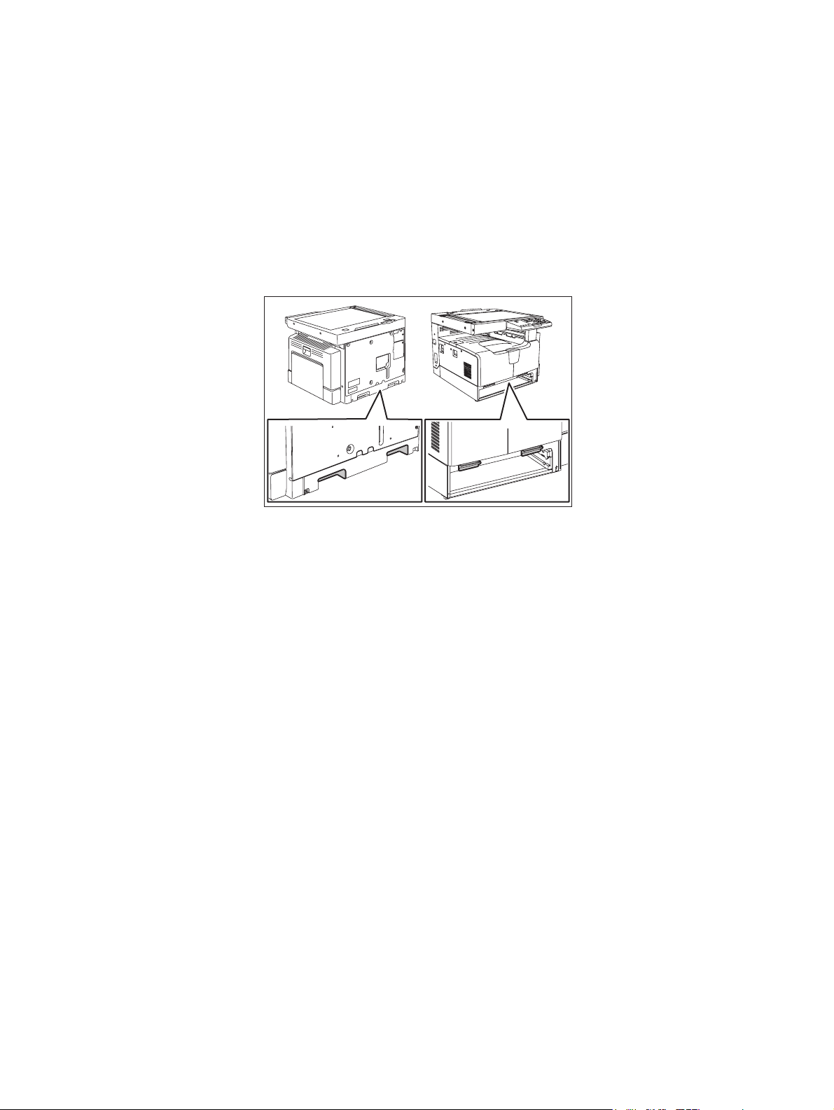
1) Transportation/Installation
- When transporting/installing the equipment, remove the drawer, employ two persons and be sure
to hold the positions as shown in the figure.
The equipment is quite heavy and weighs approximately 32 kg (70.55 lb), therefore pay full attention when handling it.
- Be sure not to hold the movable parts or units when transporting the equipment.
- Be sure to use a dedicated outlet with AC 110 V / 13.2 A, 115 V or 127 V / 12 A, 220-240 V or 240
V / 8 A for its power source.
- The equipment must be grounded for safety.
- Select a suitable place for installation. Avoid excessive heat, high humidity, dust, vibration and
direct sunlight.
- Provide proper ventilation since the equipment emits a slight amount of ozone.
- To insure adequate working space for the copying operation, keep a minimum clearance of 80
cm (32”) on the left, 80 cm (32”) on the right and 10 cm (4”) on the rear.
- The equipment shall be installed near the socket outlet and shall be easily accessible.
- Be sure to fix and plug in the power cable securely after the installation so that no one trips over
it.
06/02
Page 4

2) General Precautions at Service
- Be sure to turn the power OFF and unplug the power cable during service (except for the service
should be done with the power turned ON).
- Unplug the power cable and clean the area around the prongs of the plug and socket outlet once
a year or more. A fire may occur when dust lies on this area.
- When the parts are disassembled, reassembly is the reverse of disassembly unless otherwise
noted in this manual or other related documents. Be careful not to install small parts such as
screws, washers, pins, E-rings, star washers in the wrong places.
- Basically, the equipment should not be operated with any parts removed or disassembled.
- The PC board must be stored in an anti-electrostatic bag and handled carefully using a wristband
since the ICs on it may be damaged due to static electricity.
Caution: Before using the wristband, unplug the power cable of the equipment and
make sure that there are no charged objects which are not insulated in the
vicinity.
- Avoid expose to laser beam during service. This equipment uses a laser diode. Be sure not to
expose your eyes to the laser beam. Do not insert reflecting parts or tools such as a screwdriver
on the laser beam path. Remove all reflecting metals such as watches, rings, etc. before starting
service.
- Be sure not to touch high-temperature sections such as the exposure lamp, fuser unit, damp
heater and areas around them.
- Be sure not to touch high-voltage sections such as the chargers, developer, high-voltage trans-
former and power supply unit. Especially, the board of these components should not be touched
since the electric charge may remain in the capacitors, etc. on them even after the power is
turned OFF.
- Make sure that the equipment will not operate before touching potentially dangerous places (e.g.
rotating/operating sections such as gears, belts pulleys, fans and laser beam exit of the laser
optical unit).
- Be careful when removing the covers since there might be the parts with very sharp edges
underneath.
- When servicing the equipment with the power turned ON, be sure not to touch live sections and
rotating/operating sections. Avoid exposing your eyes to laser beam.
- Use designated jigs and tools.
- Use recommended measuring instruments or equivalents.
- Return the equipment to the original state and check the operation when the service is finished.
3) Important Service Parts for Safety
- The breaker, door switch, fuse, thermostat, thermofuse, thermistor, IC-RAMs including lithium
batteries, etc. are particularly important for safety. Be sure to handle/install them properly. If
these parts are short-circuited and their functions become ineffective, they may result in fatal
accidents such as burnout. Do not allow a short-circuit or do not use the parts not recommended
by Toshiba TEC Corporation.
4) Cautionary Labels
- During servicing, be sure to check the rating plate and cautionary labels such as “Unplug the
power cable during service”, “CAUTION. HOT”, “CAUTION. HIGH VOLTAGE”, “CAUTION.
LASER BEAM”, etc. to see if there is any dirt on their surface and if they are properly stuck to the
equipment.
Page 5

5) Disposal of the Equipment, Supplies, Packing Materials, Used Batteries and IC-RAMs
- Regarding the recovery and disposal of the equipment, supplies, packing materials, used batter-
ies and IC-RAMs including lithium batteries, follow the relevant local regulations or rules.
Caution:
Dispose of used batteries and IC-RAMs including lithium batteries according to this manual.
Attention:
Se débarrasser de batteries et IC-RAMs usés y compris les batteries en lithium selon ce manuel.
Vorsicht:
Entsorgung der gebrauchten Batterien und IC-RAMs (inclusive der Lithium-Batterie) nach diesem Handbuch.
Page 6

Page 7

CONTENTS
e-STUDIO163/203
1. SPECIFICATIONS / ACCESSORIES / OPTIONS / SUPPLIES ................................... 1-1
1.1 Specifications....................................................................................................................... 1-1
1.2 Accessories ......................................................................................................................... 1-4
1.3 Options ................................................................................................................................ 1-5
1.4 Supplies............................................................................................................................... 1-6
1.5 System List .......................................................................................................................... 1-7
2. ERROR CODE AND SELF-DIAGNOSTIC MODE........................................................ 2-1
2.1 Error Code List..................................................................................................................... 2-1
2.1.1 Jam........................................................................................................................... 2-1
2.1.2 Service call ...............................................................................................................2-2
2.2 Self-diagnosis Modes .......................................................................................................... 2-3
2.2.1 Input check (Test mode 03)...................................................................................... 2-5
2.2.2 Output check (Test mode 04) ................................................................................... 2-8
2.2.3 Test print mode (Test mode 07) ............................................................................. 2-10
2.2.4 List Print Mode (9S)................................................................................................ 2-11
2.2.5 Access code mode (8S) ......................................................................................... 2-13
2.2.6 Function Setting Mode (1*)..................................................................................... 2-15
2.2.7 Adjustment mode (05) ............................................................................................ 2-16
2.2.8 Setting mode (08) ................................................................................................... 2-32
3. ADJUSTMENT .............................................................................................................. 3-1
3.1 Adjustment of Auto-Toner Sensor ....................................................................................... 3-1
3.2 Image Dimensional Adjustment........................................................................................... 3-3
3.2.1 General description .................................................................................................. 3-3
3.2.2 Paper alignment at the registration roller ................................................................. 3-5
3.2.3 Printer related adjustment ........................................................................................ 3-7
3.2.4 Scanner related adjustment ................................................................................... 3-11
3.3 Image Quality Adjustment (Copying Function) .................................................................. 3-19
3.3.1 Density adjustment ................................................................................................. 3-19
3.3.2 Gamma slope adjustment ...................................................................................... 3-20
3.3.3 Sharpness adjustment............................................................................................ 3-21
3.3.4 Setting range correction ......................................................................................... 3-22
3.3.5 Setting range correction (Adjustment of background peak) ................................... 3-22
3.3.6 Setting range correction (Adjustment of text peak) ................................................ 3-23
3.3.7 Adjustment of smudged/faint text ........................................................................... 3-23
3.3.8 Adjustment of image density .................................................................................. 3-24
3.4 Image Quality Adjustment (Printing Function) ................................................................... 3-25
3.4.1 Adjustment of smudged/faint text ........................................................................... 3-25
3.4.2 Adjustment of image density .................................................................................. 3-26
3.5 Image Quality Adjustment (Scanning Function) ................................................................ 3-27
3.5.1 Density adjustment ................................................................................................. 3-27
3.5.2 Sharpness adjustment............................................................................................ 3-28
3.5.3 Setting range correction ......................................................................................... 3-29
3.5.4 Setting range correction (Adjustment of background peak) ................................... 3-29
3.5.5 Setting range correction (Adjustment of text peak) ................................................ 3-30
3.6 Adjustment of High-Voltage Transformer .......................................................................... 3-31
3.6.1 Adjustment ............................................................................................................. 3-31
3.6.2 Precautions ............................................................................................................ 3-37
3.7 Adjustment of the Scanner Section ................................................................................... 3-39
3.7.1 CIS unit...................................................................................................................3-39
3.7.2 CIS unit drive belt-1 ................................................................................................ 3-39
3.7.3 Scan motor (CIS unit drive belt-2) .......................................................................... 3-40
© July 2006 TOSHIBA TEC e-STUDIO163/203 CONTENTS
1
Page 8

3.8 Adjustment of the Paper Feeding System ......................................................................... 3-41
3.8.1 Sheet sideways deviation caused by paper feeding .............................................. 3-41
3.9 Adjustment of Developer Unit ............................................................................................ 3-42
3.9.1 Doctor-to-sleeve gap .............................................................................................. 3-42
3.10 Adjustment of the ADF (MR-2017) .................................................................................... 3-45
3.10.1 Adjustment of ADF Position ................................................................................... 3-45
3.10.2 Adjustment of ADF Height...................................................................................... 3-50
3.10.3 Adjustment of Skew................................................................................................ 3-52
3.10.4 Adjustment of the Leading Edge Position .............................................................. 3-54
3.10.5 Adjustment of Horizontal Position .......................................................................... 3-55
3.10.6 Adjustment of Copy Ratio....................................................................................... 3-56
3.10.7 Adjustment of ADF Opening/Closing Sensor ......................................................... 3-57
4. PREVENTIVE MAINTENANCE (PM)............................................................................ 4-1
4.1 General Descriptions for PM Procedure .............................................................................. 4-1
4.2 Operational Items in Overhauling ........................................................................................ 4-2
4.3 Preventive Maintenance Checklist....................................................................................... 4-3
4.4 PM KIT............................................................................................................................... 4-12
4.5 Jig List ............................................................................................................................... 4-13
4.6 Grease List ........................................................................................................................ 4-14
4.7 Precautions for Storing and Handling Supplies ................................................................. 4-15
4.7.1 Precautions for storing TOSHIBA supplies ............................................................ 4-15
4.7.2 Checking and cleaning of photoconductive drum................................................... 4-16
4.7.3 Checking and cleaning of drum cleaning blade...................................................... 4-17
4.7.4 Checking and cleaning of fuser roller and pressure roller ...................................... 4-17
5. TROUBLESHOOTING .................................................................................................. 5-1
5.1 Diagnosis and Prescription for Each Error Code ................................................................. 5-1
5.1.1 Paper transport jam .................................................................................................. 5-1
5.1.2 Paper misfeeding ..................................................................................................... 5-4
5.1.3 Cover open jam ........................................................................................................ 5-7
5.1.4 Transport jam (ADF)............................................................................................... 5-10
5.1.5 Drive system related service call ............................................................................ 5-13
5.1.6 Scanning system related service call ..................................................................... 5-14
5.1.7 Fuser unit related service call................................................................................. 5-15
5.1.8 ADF related service call ......................................................................................... 5-17
5.1.9 Laser optical unit related service call ..................................................................... 5-17
5.1.10 Service call for others............................................................................................. 5-18
5.2 Troubleshooting for the Image........................................................................................... 5-19
5.3 Replacement of PC Boards ............................................................................................... 5-41
5.3.1 Replacing MAIN board ........................................................................................... 5-41
5.3.2 Replacing SRAM board .......................................................................................... 5-41
6. FIRMWARE UPDATING ............................................................................................... 6-1
6.1 Firmware Updating with Download Jig ................................................................................ 6-1
6.1.1 PWA-DWNLD-350-JIG ............................................................................................. 6-3
6.1.2 Writing the data to the download jig (PWA-DWNLD-350-JIG) ................................. 6-6
6.1.3 K-PWA-DLM-320...................................................................................................... 6-7
6.2 Firmware Updating with TOSHIBA Viewer .......................................................................... 6-8
7. POWER SUPPLY UNIT ................................................................................................ 7-1
7.1 Output Channel ................................................................................................................... 7-1
7.2 Fuse..................................................................................................................................... 7-2
7.3 Configuration of Power Supply Unit..................................................................................... 7-3
e-STUDIO163/203 CONTENTS © July 2006 TOSHIBA TEC
2
Page 9

8. WIRE HARNESS CONNECTION.................................................................................. 8-1
8.1 AC Wire Harness ................................................................................................................. 8-1
8.2 DC Wire Harness....................................................................................................... Appendix
8.3 Electric Parts Layout.................................................................................................. Appendix
© July 2006 TOSHIBA TEC e-STUDIO163/203 CONTENTS
3
Page 10

e-STUDIO163/203 CONTENTS © July 2006 TOSHIBA TEC
4
Page 11

1. SPECIFICATIONS / ACCESSORIES /
OPTIONS / SUPPLIES
2. ERROR CODE AND SELF-DIAGNOSTIC
MODE
3. ADJUSTMENT
4. PREVENTIVE MAINTENANCE (PM)
5. TROUBLESHOOTING
1
2
3
4
5
6. FIRMWARE UPDATING
7. POWER SUPPLY UNIT
8. WIRE HARNESS CONNECTION
6
7
8
Page 12

Page 13
1. SPECIFICATIONS / ACCESSORIES / OPTIONS / SUPPLIES
1.1 Specifications
Values in [ ] are for e- STUDIO203 in case that the specification is different among e-STUDIO163
and e-STUDIO203.
Copy process Indirect electrophotographic process (dry)
Type Desktop type
Original table Fixed type (the left rear corner used as guide to place originals)
Accepted originals Sheet, book and 3-dimensional object. The automatic document feeder
(ADF) only accepts paper which are not pasted or stapled. (Single-sided orig-
inals: 50 to 127 g/m
either.
Maximum size: A3/LD
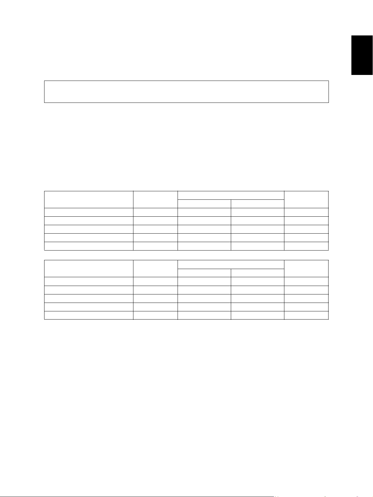
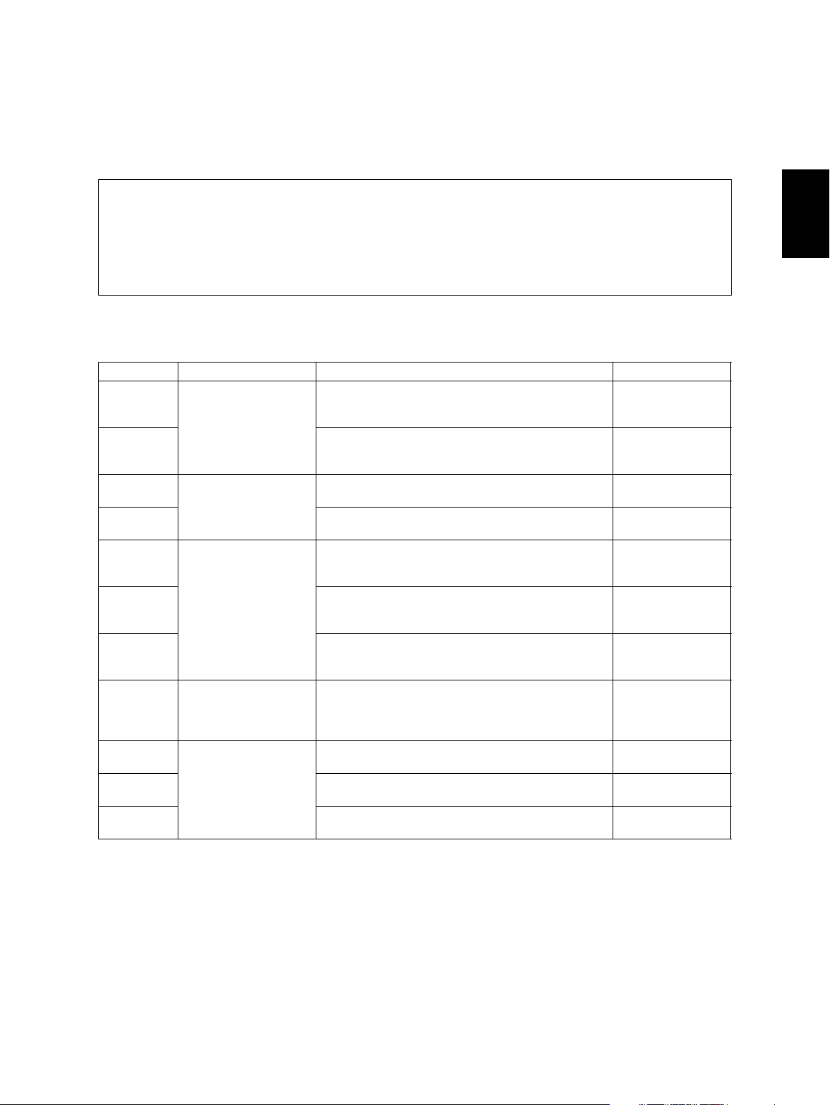
Copy speed (Copies/min.)
e-STUDIO163
Paper size Drawer
A4, B5, LT 16 16 11 16
A5-R, ST-R - 16 11 -
A4-R, B5-R, LT-R 15.5 15.5 11 15.5
B4, LG, FOLIO, COMPUTER 13 13 11 13
A3 , L D 11 11 11 11
2
/13 to 34 lb. Bond) Carbon paper are not acceptable
Bypass feed
Size specified Size not specified
PFU
1
e-STUDIO203
Paper size Drawer
A4, B5, LT 20 20 11 20
A5-R, ST-R - 20 11 -
A4-R, B5-R, LT-R 15.5 15.5 11 15.5
B4, LG, FOLIO, COMPUTER 13 13 11 13
A3 , L D 11 11 11 11
Size specified Size not specified
Bypass feed
PFU
* “–” means “Not acceptable”.
* The copy speed in the above table are available when originals are manually placed for single side,
multiple copying.
* When the ADF is used, the copy speed of 16[20] sheets per minute is only available under the fol-
lowing conditions:
• Original/Mode: Single side original/A4/LT size. APS/automatic density are not selected.
• Number of sheets: 16[20] or more.
• Reproduction ratio: 100%
© December 2005 TOSHIBA TEC e-STUDIO163/203 SPECIFICATIONS / ACCESSORIES / OPTIONS / SUPPLIES
1 - 1
Page 14

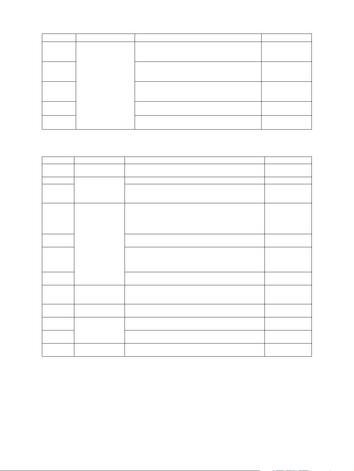
Copy speed for thick paper (Copies/min.)
e-STUDIO163/203
2
Thick 1 (81 g/m
Thick 2 (106 g/m
to 105 g/m2, 21.3 lb. Bond to 28 lb. Bond): Bypass feed on a sheet by sheet basis only
2
to 163 g/m2, 28 lb. Bond to 90 lb. Index): Bypass feed on a sheet by sheet basis only
Copy paper
Drawer PFU Bypass copy Remarks
Size A3, A4, A4-R, B4, B5,
B5-R, LD, LG, LT, LT-R,
FOLIO, COMPUTER,
13"LG, 8.5" x 8.5", 8K,
16K, 16K-R
Weight
Special
paper
64 to 80 g/m
– Tracing paper, labels, OHP film
2
A3 to A5-R, LD to ST-R, FOLIO, COMPUTER, 13"LG, 8.5" x 8.5", 8K, 16K,
16K-R
(Non-standard or user-specified sizes
can be set.)
50 to 163 g/m2(Single paper feeding)
64 to 80 g/m2(Continuous feeding)
(thickness: 80 µm or thicker),
These special papers recommended by Toshiba Tec
First copy time ..................... Approx. 7.6 sec. (A4, 100%, original placed manually)
Approx. 7.7 sec. (LT, 100%, original placed manually)
Warming-up time.................. Approx. 25 sec. (temperature: 20°C)
Multiple copying ................... Up to 999 copies; Key in set numbers
Reproduction ratio ............... Actual ratio: 100±0.5%
Zooming: 25 to 200% in increments of 1%
Resolution/Gradation ........... Scanning: 600 dpi x 600 dpi
Printing: Equivalent to 2400 dpi x 600 dpi
Gradation: 256 steps
Eliminated portion ................ Leading edges: 3.0±2.0 mm, Side/trailing edges: 2.0±2.0 mm (copy)
Leading / trailing edges: 5.0±2.0 mm, Side edges: 5.0±2.0 mm (print)
Paper feeding ......................... Standard drawer:
1 drawer (stack height 28 mm, equivalent to 250 sheets; 64 to
80 g/m
2
(17 to 22 lb. Bond))
Bypass feeding:
Stack height 11.8 mm: equivalent to 100 sheets; 64 to 80 g/m
(17 to 22 lb. Bond)
Paper Feed Unit (PFU):
Option (One drawer: stack height 28 mm, equivalent to 250
sheets; 64 to 80 g/m
2
(17 to 22 lb. Bond))
Capacity of originals in the automatic document feeder (Option)
.................................................. A3 to A5-R, LD to ST-R:
100 sheets / 80 g/m
2
(Stack height 16 mm or less)
Toner supply........................... Automatic toner density detection/supply
Toner cartridge replacing method (There is a recovered toner supply
mechanism.)
2
e-STUDIO163/203 SPECIFICATIONS / ACCESSORIES / OPTIONS / SUPPLIES © December 2005 TOSHIBA TEC
1 - 2
06/04
Page 15
Density control ..................... Automatic density mode and manual density mode selectable in 7
steps
Weight.................................. Approximately 32 kg (70.55 lb.) (excluding the developer material and
toner)
Power requirements............. AC 110 V / 13.2 A, 115 V or 127 V / 12 A
220-240 V or 240 V / 8 A (50/60 Hz)
* The acceptable value of each voltage is ±10%.
Power consumption ............. 1.5 kW or less (100 V series)
1.6 kW or less (200 V series)
* The electric power is supplied to the ADF and PFU through the equipment.
Total counter ........................ Electronical counter
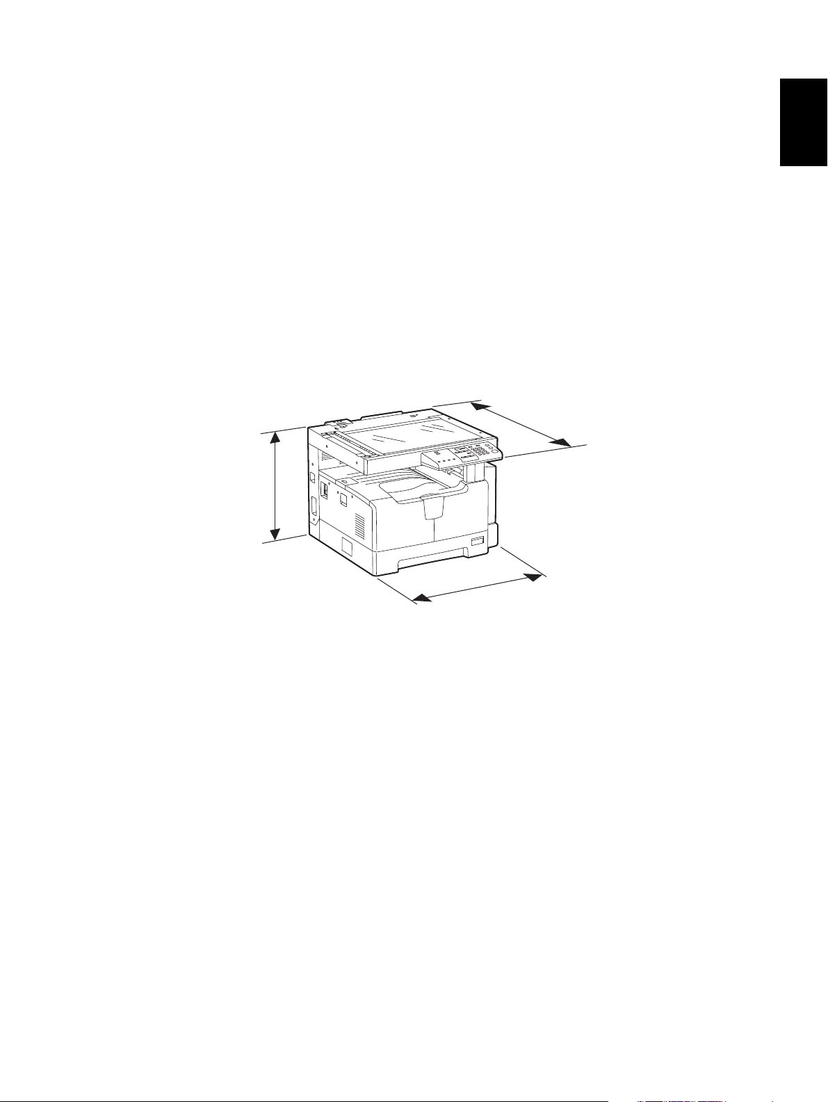
Dimensions of the equipment
.................................................. W 600 x D 643 x H 462.5 (mm): See the figure below
D
1
H
W
Fig. 1-1
© December 2005 TOSHIBA TEC e-STUDIO163/203 SPECIFICATIONS / ACCESSORIES / OPTIONS / SUPPLIES
1 - 3
06/04
Page 16

1.2 Accessories
Unpacking/setup instruction 1 set
Operator’s manual 1 pc.
Operator's manual pocket 1 pc.
Power cable 1 pc.
CD-ROM 2 pcs.
Rubber plug 6 pcs.
Transfer charger wire cleaner
(installed inside of the transfer cover)
Drum (installed inside of the equipment) 1 pc.
Developer material 1 pc.
Nozzle 1 pc.
Toner cartridge 1 pc.
Warranty sheet 1 pc. (for NAD and CND)
Setup report 1 set (for NAD, MJD and CND)
Customer satisfaction card 1 pc. (for MJD)
Packing list 1 pc. (for CND)
Customer survey sheet 1 pc. (for CND)
Certificate of conformance 1 pc. (for CND)
1 pc.
* Machine version
NAD: North America
ASD: Hong Kong / Latin America
AUD: Australia
MJD: Europe
ASU: Asia / Saudi Arabia
SAD: Saudi Arabia
ARD: Latin America
CND: China
TWD: Taiwan
KRD: Korea
JPD: Japan
e-STUDIO163/203 SPECIFICATIONS / ACCESSORIES / OPTIONS / SUPPLIES © December 2005 TOSHIBA TEC
1 - 4
06/04
Page 17

1.3 Options
Platen Cover KA-1640 PC
Automatic Document Feeder (ADF) MR-2017
Paper Feed Unit (PFU) MY-1027 / C
Expansion Memory GC-1240
1
© December 2005 TOSHIBA TEC e-STUDIO163/203 SPECIFICATIONS / ACCESSORIES / OPTIONS / SUPPLIES
1 - 5
Page 18

1.4 Supplies
Drum OD-1600 (except for China)
OD-2320 (for China)
Toner cartridge PS-ZT1640 (4) (for North America)
Developer material D-2320 (except for China)
PS-ZT1640D (4) (for Asia, Central and South America)
PS-ZT1640D5K (4) (for Asia, Central and South America)
PS-ZT1640C (4) (for China)
PS-ZT1640C5K (4) (for China)
PS-ZT1640T (4) (for Taiwan)
PS-ZT1640E (1) (for Europe)
PS-ZT1640E5K (1) (for Europe)
D-2320C (for China)
e-STUDIO163/203 SPECIFICATIONS / ACCESSORIES / OPTIONS / SUPPLIES © December 2005 TOSHIBA TEC
1 - 6
Page 19
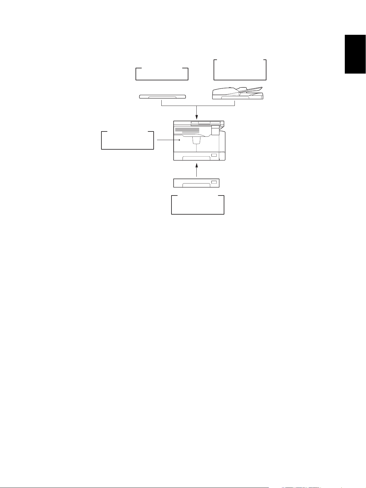
1.5 System List
Expansion
Memory
GC-1240
Platen Cover
KA-1640PC
Paper Feed
Unit (PFU
MY-1027
Fig. 1-2
Automatic
Document Feeder
(
ADF
MR-2017
)
1
)
© December 2005 TOSHIBA TEC e-STUDIO163/203 SPECIFICATIONS / ACCESSORIES / OPTIONS / SUPPLIES
1 - 7
Page 20

e-STUDIO163/203 SPECIFICATIONS / ACCESSORIES / OPTIONS / SUPPLIES © December 2005 TOSHIBA TEC
1 - 8
Page 21
2. ERROR CODE AND SELF-DIAGNOSTIC MODE
2.1 Error Code List
• One of the following error codes is displayed with “7-segment LED” while pressing the [CLEAR/
STOP] button and the digital key [8] simultaneously when the “CLEAR PAPER” or “CALL
SERVICE” symbol is blinking.
• "CALL SERVICE" symbol blinks: A service call occurs.
• "CALL SERVICE" symbol lights: PM cycle (This symbol lights at the time of preventive maintenance. Copying can be performed.)
2.1.1 Jam
Error code Classification Contents Troubleshooting
E01 Paper exit jam Jam not reaching the exit sensor: The paper which
has passed through the fuser unit does not reach
the exit sensor.
E02 Stop jam at the exit sensor: The trailing edge of the
paper does not pass the exit sensor after its leading
edge has reached this sensor.
E03 Other paper jam Power-ON jam: The paper is remaining on the
paper transport path when power is turned ON.
E09 Jam at the registration area due to registration time-
out error
E12 Paper misfeeding Bypass misfeeding (Paper not reaching the regis-
tration sensor): The paper fed from the bypass tray
does not reach the registration sensor.
E13 Drawer misfeeding (Paper not reaching the regis-
tration sensor): The paper fed from the drawer does
not reach the registration sensor.
E14 PFU drawer misfeeding (Paper not reaching the
PFU feed sensor): The paper fed from the PFU
drawer does not reach the PFU feed sensor.
E21 Paper transport jam PFU drawer transport jam (Paper not reaching the
registration sensor): The paper does not reach the
registration sensor after it has passed the PFU feed
sensor.
E40 Cover open jam Transfer cover open jam: The transfer cover has
opened during printing.
E41 Front cover open jam: The front cover has opened
during printing.
E44 PFU cover open jam: The PFU cover has opened
during printing.
P. 5 - 1
P. 5 - 1
P. 5 - 2
-
P. 5 - 4
P. 5 - 5
P. 5 - 6
P. 5 - 3
P. 5 - 7
P. 5 - 8
P. 5 - 9
2
© December 2005 TOSHIBA TEC e-STUDIO163/203 ERROR CODE AND SELF-DIAGNOSTIC MODE
2 - 1
06/11
Page 22
Error code Classification Contents Troubleshooting
E71 ADF jam Jam not reaching the original registration sensor:
P. 5 - 10
The original fed from the original feeding tray does
not reach the original registration sensor.
E72 Jam not reaching the read sensor: The original
P. 5 - 10
does not reach the read sensor after it has passed
the registration sensor.
E73 Stop jam at the exit sensor: The trailing edge of the
P. 5 - 11
original does not pass the exit sensor after its leading edge has reached this sensor.
E86 ADF jam access cover open: The ADF jam access
P. 5 - 11
cover has opened during ADF operation.
E87 ADF open jam: ADF has opened during ADF opera-
P. 5 - 12
tion.
2.1.2 Service call
Error code Classification Contents Troubleshooting
C01 Drive system
related service call
C21 Scanning system
C26 Peak detection error: Lighting of the exposure lamp
related service call
C41 Fuser unit related
service call
C43 Thermistor abnormality during warming up or in ready
C44 Heater abnormality after abnormality judgment: The tem-
C45 Thermistor abnormality during printing: Abnormality of the
C55 Optional communi-
cation related ser-
vice call
C97 Process related
service call
CA1 Laser optical unit
related service call
CA2 H-Sync detection error: H-Sync detection PC board can-
F14 Other service call Invalid backup counter: The value of the total counter is
Main motor abnormality: The main motor is not rotating
P. 5-13
normally.
CIS unit initialization error -
P. 5-14
(white reference) is not detected when power is turned
ON.
Thermistor or heater abnormality at power-ON: Abnor-
P. 5-15
mality of service call the thermistor is detected when
power is turned ON or the temperature of the fuser roller
does not rise in a specified period of time after power is
turned ON.
status after abnormality judgment
P. 5-16
perature of the fuser roller has exceeded the range of
control (in this case, the main switch turns OFF automatically) or does not even reach the range.
P. 5-16
thermistor is detected during printing.
ADF I/F error: Communication error has occurred
between the ADF and the scanner
High-voltage transformer abnormality: Leakage of the
P. 5-18
main charger is detected.
Polygonal motor abnormality: The polygonal motor is not
P. 5-17
rotating normally.
P. 5-17
not detect laser beams.
P. 5-18
inconsistent with that of the backup counter.
-
-
e-STUDIO163/203 ERROR CODE AND SELF-DIAGNOSTIC MODE © December 2005 TOSHIBA TEC
2 - 2
06/04
Page 23

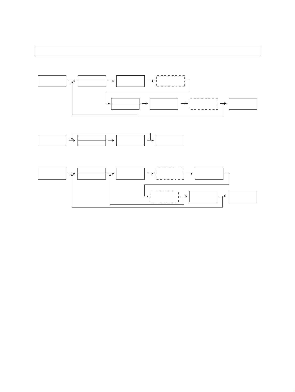
2.2 Self-diagnosis Modes
Mode For start Contents For exit Display
Input check
mode
[0]+[3]+
[POWER]
Checks the status of input signals. [POWER]
OFF/ON
Output check
mode
Te s t p r in t
mode
Adjustment
mode
Setting mode [0]+[8]+
List print mode [9]+[START]
Access code
mode
Function setting mode
[0]+[4]+
[POWER]
[0]+[7]+
[POWER]
[0]+[5]+
[POWER]
[POWER]
+[POWER]
[8]+[START]
+[POWER]
[1]+[*]+
[POWER]
Checks the status of output signals. [POWER]
OFF/ON
Outputs the test patterns. [POWER]
OFF/ON
Adjusts various items. [POWER]
OFF/ON
Sets various items. [POWER]
OFF/ON
Prints out the data lists of the codes 05/08 and
pixel counter.
[POWER]
OFF/ON
Registers / deletes the access code. [POWER]
OFF/ON
Sets the function table. [POWER]
OFF/ON
Note: Note:
To enter the desired mode, turn ON the power while two digital keys designated to each mode
(e.g. [0] and [5]) are pressed simultaneously.
2
[POWER]
Warming up
Ready
[POWER]
OFF
To user
*1
Normal
Input check
[0][3] [0][4]
mode
Output check
mode
ON
[0][7] [0][5] [0][8] [1][*][9][START] [8][START]
Test print
mode
Adjustment
mode
Setting
mode
List print
mode
Access code
mode
Function
setting mode
State transition diagram of self-diagnosis modes
Fig. 2-1
*1 Turn OFF the power after using the self-diagnosis modes, and leave the equipment to the user.
© December 2005 TOSHIBA TEC e-STUDIO163/203 ERROR CODE AND SELF-DIAGNOSTIC MODE
2 - 3
Page 24
<Operation procedure>
• Input check mode (03): Refer to P. 2-5 "2.2.1 Input check (Test mode 03)".
• Output check mode (04): Refer to P. 2-8 "2.2.2 Output check (Test mode 04)".
• Test print mode (07): Refer to P. 2-10 "2.2.3 Test print mode (Test mode 07)".
• Adjustment mode (05): Refer to P. 2-16 "2.2.7 Adjustment mode (05)".
• Setting mode (08): Refer to P. 2-32 "2.2.8 Setting mode (08)".
• List print mode (9S):Refer to P. 2-11 "2.2.4 List Print Mode (9S)"
• Access code mode (8S): P. 2-13 "2.2.5 Access code mode (8S)"
• Function setting mode (1*): P. 2-15 "2.2.6 Function Setting Mode (1*)"
<Number display>
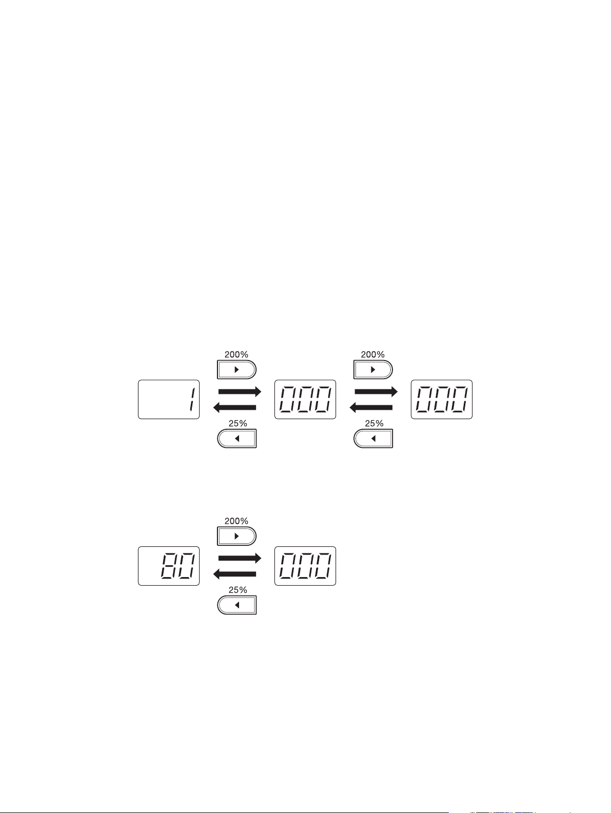
The numbers are displayed on a 7-segment LED.
A number of more than 3 digits long is separated as follows, and is displayed from the high-order position. Press the reproduction ratio button ([200%] or [25%]) to shift the display to the 3 digits of the next
lower/higher order.
E.g.1) Displaying 1,000,000
Fig. 2-2
E.g. 2) Displaying 80,000
Fig. 2-3
e-STUDIO163/203 ERROR CODE AND SELF-DIAGNOSTIC MODE © December 2005 TOSHIBA TEC
2 - 4
Page 25
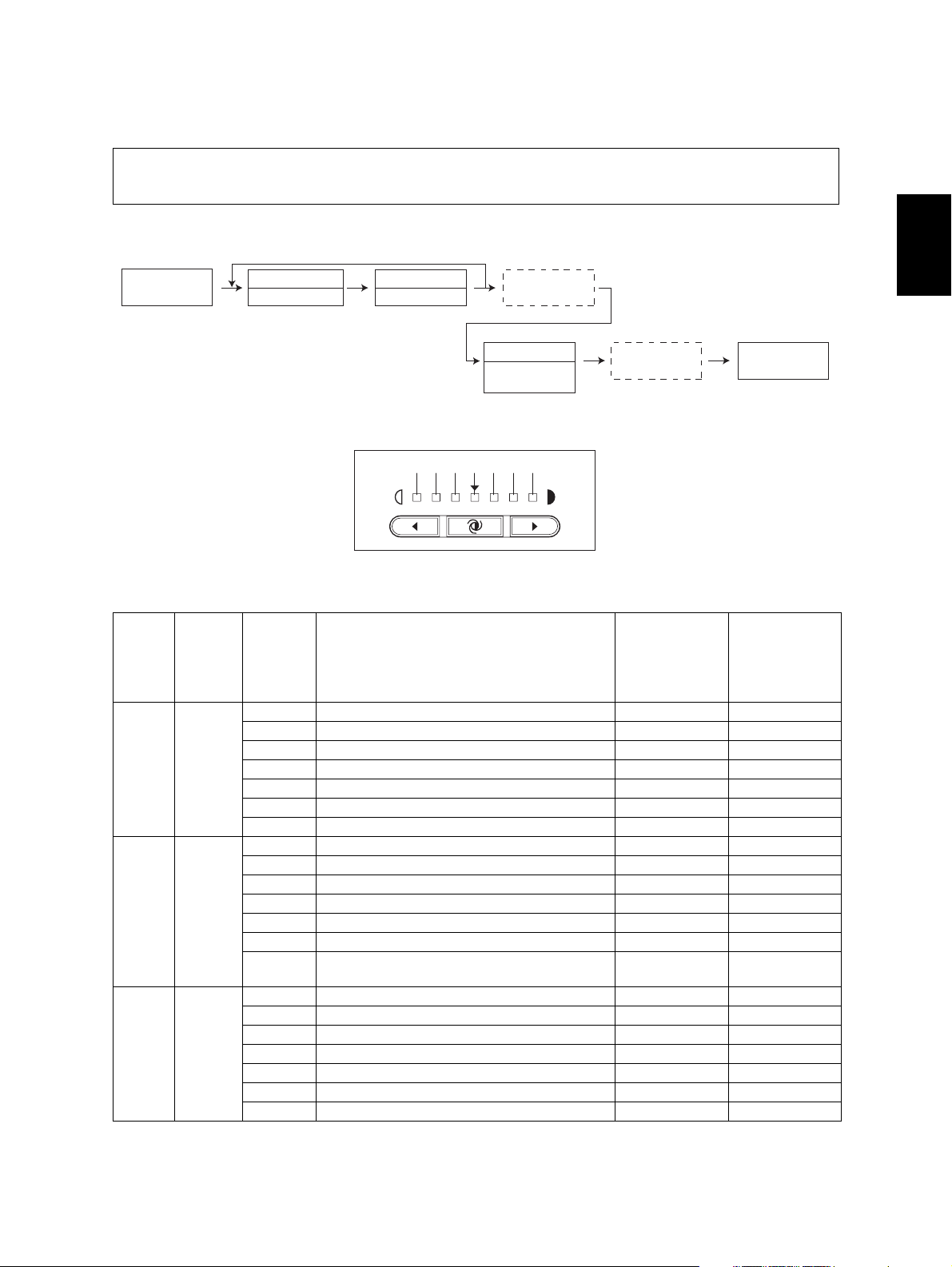
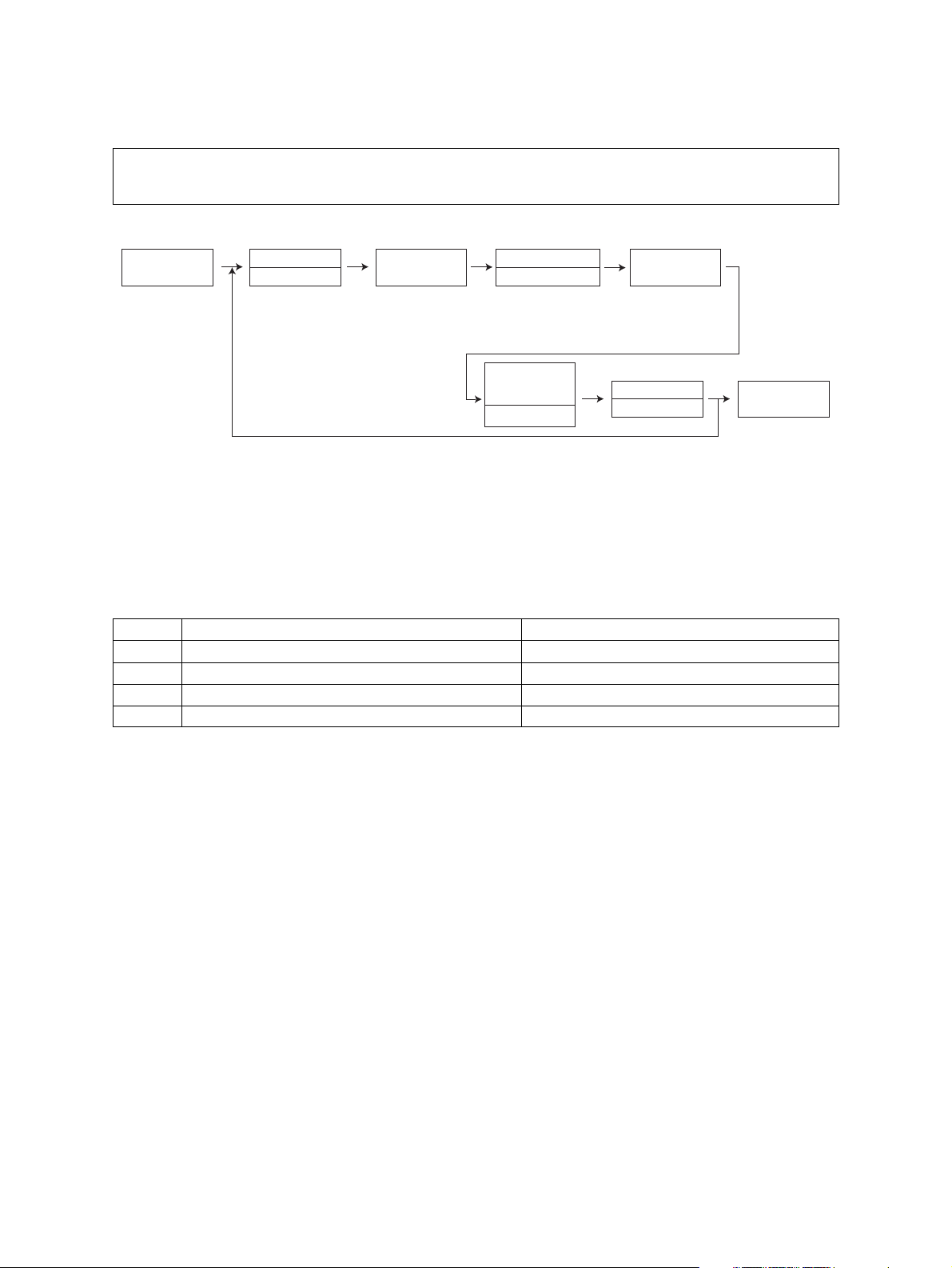
2.2.1 Input check (Test mode 03)
The status of each input signal can be checked by pressing the [INTERRUPT] button, and the digital keys in the test mode (03).
<Operation procedure>
[0][3]
[POWER]
Group
[INTERRUPT]
Number
[Digital keys]
LED ON
END
[FUNCTION
CLEAR]
LED OFF
[POWER]
OFF/ON
Group is displayed by ON/OFF of the [INTERRUPT] LED, and the number keyed in is displayed with
the 7-segment LED. Each status is indicated by ON/OFF of the 7 [DENSITY LED] s.
6543210
Fig. 2-4 Display position of the density LED
Display
[INTER
RUPT]
LED
OFF [1]
OFF [4]
OFF [6]
Number
[Digital
keys]
position
of the
density
LED
0- -1- -2- -3- -4 Bypass paper sensor No paper Paper present
5 Bypass unit connection Not connected Connected
6- -0- -1- -2- -3- -4- -5 Paper empty sensor No paper Paper present
6 Drawer detection switch Drawer not
0- -1- -2- -3- -4- -5 PFU paper empty sensor No paper Paper present
6- --
Items to check ON OFF
Drawer
installed
installed
2
© December 2005 TOSHIBA TEC e-STUDIO163/203 ERROR CODE AND SELF-DIAGNOSTIC MODE
2 - 5
Page 26
[INTER
RUPT]
Number
[Digital
LED
OFF [7]
OFF [8]
OFF [9]
OFF [0]
keys]
Display
position
of the
Items to check ON OFF
density
LED
0- -1- -2- -3- -4- -5 PFU feed sensor Paper present No paper
6 PFU drawer detection switch No drawer Drawer present
0- -1- -2 Polygonal motor rotation status (Open the
platen cover)
Abnormal rotation
Normal rotation
3- -4 PFU board connection Not connected Connected
5- -6 24 V power supply
24 V OFF 24 V ON
(Front cover opening/closing)
0- -1- -2 PFU cover opening/closing switch Cover opened Cover closed
3 Front cover opening/closing switch Cover opened Cover closed
4- -5 Exit sensor Paper present No paper
6 Registration sensor Paper present No paper
0- -1- -2- -3 Developer unit switch Not connected Connected
4 Fuser unit switch Connected Not connected
5- -6 Externally counter connection Not connected Connected
e-STUDIO163/203 ERROR CODE AND SELF-DIAGNOSTIC MODE © December 2005 TOSHIBA TEC
2 - 6
06/11
Page 27
[INTER
RUPT]
LED
ON [1]
ON [2]
ON [4]
ON [5]
Number
[Digital
keys]
Display
position
of the
Items to check ON/Blinking OFF
density
LED
0- -1- -2- -3- -4- -5 High-voltage transformer error Normal Error
6- -0- -1- -2- -3- -4 CIS home position sensor Home position Other than
home position
5 Platen sensor Cover opened Cover closed
6 ADF connection Connected Not connected
0 ADF read sensor Original
No original
present
1- -2 ADF exit sensor Original
No original
present
3 ADF opening/closing sensor ADF opened ADF closed
4 ADF cover opening/closing sensor Cover opened Cover closed
5 ADF empty sensor Original
No original
present
6 ADF tray sensor Original
No original
present
0- -1- -2- -3 ADF original width sensor-2 Original
No original
present
4 ADF original width sensor-1 Original
No original
present
5 ADF original length sensor Original
No original
present
6 ADF registration sensor Original
No original
present
2
© December 2005 TOSHIBA TEC e-STUDIO163/203 ERROR CODE AND SELF-DIAGNOSTIC MODE
2 - 7
06/11
Page 28
2.2.2 Output check (Test mode 04)
Status of the output signals can be checked by keying in the following codes in the test mode 04.
<Operation procedure>
Procedure 1
[0][4]
[POWER]
Procedure 2
[0][4]
[POWER]
Procedure 3
[0][4]
[POWER]
Code
[Digital keys]
Code
[Digital keys]
Code
[Digital keys]
[START]
Stop code
[Digital keys]
[START]
[START] [CLEAR]
Operation
ON
[START]
[POWER]
OFF/ON
Operation
ON
Operation
OFF
Operation
[FUNCTION
CLEAR]
OFF
[POWER]
OFF/ON
[POWER]
OFF/ON
e-STUDIO163/203 ERROR CODE AND SELF-DIAGNOSTIC MODE © December 2005 TOSHIBA TEC
2 - 8
Page 29

Code Function Code Function Procedure
101 Main motor ON (operational without
151 Code No. 101 function OFF 1
developer unit)
102 Toner motor ON (normal rotation) 152 Code No. 102 function OFF 1
103 Polygonal motor ON (600 dpi) 153 Code No. 103 function OFF 1
108 Registration clutch ON 158 Code No. 108 function OFF 1
110 ADU motor ON (low speed) 160 Code No. 110 function OFF 1
118 Laser ON 168 Code No. 118 function OFF 1
201 Pickup solenoid ON/OFF 3
202 PFU pickup solenoid ON/OFF 3
203 PFU transport clutch (high speed) ON/OFF 3
204 Bypass pickup solenoid ON/OFF 3
205 PFU transport clutch (low speed) ON/OFF 3
218 Key copy counter count up 2
235 Discharge LED ON/OFF 3
236 Exhaust fan ON/OFF (low speed) 3
237 Exhaust fan ON/OFF (high speed) 3
249 Developer bias [-DC] ON/OFF 3
252 Main charger ON/OFF 3
253 Separation bias ON/OFF 3
255 Transfer guide bias ON/OFF 3
256 Transfer transformer ON/OFF 3
261 Scan motor ON (Automatically stops at limit position) 2
267 Contact image sensor (CIS) Unit ON/OFF 3
281 ADF feed motor ON/OFF (normal rotation) 3
282 ADF feed motor ON/OFF (reverse rotation) 3
283 ADF read motor ON/OFF (normal rotation) 3
410 Switching regulator cooling fun ON/OFF (low speed) 3
411 Switching regulator cooling fun ON/OFF (high speed) 3
2
© December 2005 TOSHIBA TEC e-STUDIO163/203 ERROR CODE AND SELF-DIAGNOSTIC MODE
2 - 9
06/11
Page 30
2.2.3 Test print mode (Test mode 07)
The embedded test pattern can be printed out by keying in the following codes in the test print mode
(07).
<Operation procedure>
[0][7]
[POWER]
Code
[Digital keys] [Digital keys]
[START] [START]
Drawer number
0: Bypass
1: Drawer
2: PFU
Operation
Continuous
Test Printing
[START]
Stop
[CLEAR]
[POWER]
OFF/ON
Notes:
1. Test printing is set by default to continue until the [CLEAR] button is pressed, or an error
occurs. Note that printing may therefore continue until the paper set in the specified drawer
completely runs out.
2. When an error occurs, it is indicated on the panel, but the recovery operation is not performed. Turn OFF the power and then back ON to clear the error.
3. During test printing, all button operations are disabled when the Message lamps on the control panel light.
Code Types of test pattern Remarks
111 Primary scanning direction 33 gradation steps Error diffusion
113 Secondary scanning direction 33 gradation steps Error diffusion
142 Grid pattern Pattern width: 2 dots, Pitch: 10 mm
149 Solid black pattern (Whole area) A3/LD
e-STUDIO163/203 ERROR CODE AND SELF-DIAGNOSTIC MODE © December 2005 TOSHIBA TEC
2 - 10
06/04
Page 31

2.2.4 List Print Mode (9S)
Lists of the function setting, adjustment mode (05), setting mode (08), system setting, memory
dump, etc. can be output in this mode.
ROM versions of the System firmware and scanner (ADF) are printed on the top right of each list.
• T280SY0Wxxx: System firmware ROM version
• Vxxxx: Scanner ROM version (ADF ROM version)
<Setting procedure>
101: FUNC (FUNC, 05/08) data list
102: System setting list
2
[9][START]
[POWER]
List code
[Digital keys]
101:FUNC (FUNC,05/08) Data list
102:FUNCTION list
List starts
to be printed
[START]
[POWER]
OFF/ON
103: Memory dump list
Address
[9][START]
[POWER]
List code
[Digital keys] [Digital keys]
103:Memory dump list
[START]
specification
(6 digits)
Size
specification
[Digital keys]
(4 digits)
[START]
Outputs a memory dump list of a specified size from a specified address.
Notes:
• Key in 6 digits for the address specification and 4 digits for the size specification.
• Key in using the digital keys as in the table below to enter the letters A to F.
Letter of alphabet A B C D E F
Digital keys [*] [0] [*] [1] [*] [2] [*] [3] [*] [4] [*] [5]
[START]
[POWER]
OFF/ON
E.g.)When outputting an 80 size dump list from the address 0x0000A0
Display Key-in order
Address specification (6 digits) 0000A0 [0] -> [0] -> [0] -> [0] -> [*] -> [0] -> [0]
Size specification (4digits) 0080 [0] -> [0] -> [8] -> [0]
© December 2005 TOSHIBA TEC e-STUDIO163/203 ERROR CODE AND SELF-DIAGNOSTIC MODE
2 - 11
06/04
Page 32

Output sample (103: Memory dump list)
Fig. 2-5
e-STUDIO163/203 ERROR CODE AND SELF-DIAGNOSTIC MODE © December 2005 TOSHIBA TEC
2 - 12
06/04
Page 33

2.2.5 Access code mode (8S)
Storing/deleting of the access code, and confirming and changing of the counter value can be done
in the access code mode (8S).
Note: Note:
Department management must be enabled in FUNC-18 (bit-2) before you can use a registered
access code.
<Setting procedure>
Registering the access code
Stores
value in RAM
[START]
[8][START]
[POWER]
Access code
[Digital keys]
(3 digits)
Notes:
• Register up to 99 access codes in 3-digit numbers from 001 to 999.
• If the [START] button is pressed with an access code which has been already registered, a
beep sounds and the display returns to the initial screen.
Confirm
[START]
Access code
(blinks)
Does not store
value in RAM
[CLEAR]
[POWER]
OFF/ON
2
Deleting the access code
Auto search
[INTERRUPT]
[8][START]
[POWER]
Access code
[Digital keys]
Access code
Confirm
[FUNCTION
CLEAR]
"---"
(blinks)
Deleting
[FUNCTION
CLEAR]
Cancel
[CLEAR]
Notes:
• Auto search for the access code: Every time the [INTERRUPT] button is pressed, registered
access codes are displayed in order.
• If the [START] button is pressed with an access code which has not been registered previously, the display returns to the initial screen.
[POWER]
OFF/ON
© December 2005 TOSHIBA TEC e-STUDIO163/203 ERROR CODE AND SELF-DIAGNOSTIC MODE
2 - 13
Page 34

Confirming and changing of the access code counter value
Auto search
[INTERRUPT]
[8][START]
[POWER]
Access code
[Digital keys]
Displaying
3 digits
Correct
[Digital keys]
Access code
Displays
higher digits
[200%]
Displays
lower digits
[25%]
Confirm
[200%]
Displaying
3 digits
Correct
[Digital keys]
Confirm
[25%]
Displays
higher digits
[200%]
Displays
lower digits
[25%]
Stores
value in RAM
[START]
Displaying
3 digits
Correct
[Digital keys]
[POWER]
OFF/ON
Notes:
• A counter value is separated as follows: 1 000 280 070, and is displayed from the high-order
position. Press the reproduction ratio button ([200%] or [25%]) to shift the counter value display to the 3 digits of the next lower/higher order.
• Change of the counter value can be registered only after the [START] button is pressed. If the
[CLEAR] button is pressed before the registration is completed, the changed value is also
canceled.
• Only the total counter value for each access code can be confirmed.
<Operation procedure>
Follow the procedure bellow to key in an access code when the access code mode is set.
When an access code
"Displays the access
code mode"
[POWER]
*: Apply the same procedure when the equipment enters the interruption mode.
Key in access code
[Digital keys]
Cancel
[CLEAR]
[START]
When an access code
registered previously
which has already been
registered is entered
"Displays number of copies"
which has not been
is entered
Normal
operation
e-STUDIO163/203 ERROR CODE AND SELF-DIAGNOSTIC MODE © December 2005 TOSHIBA TEC
2 - 14
06/04
Page 35

2.2.6 Function Setting Mode (1*)
The function tables can be set in the function setting mode (1*).
Each function table consists of 8 bits, and each bit is assigned to one function. To set a function,
place a 0 or 1 in the bit which enables the function you want to set.
<Operation procedure>
2
[1][*]
[POWER]
FUNC type
[Digital keys] [Digital keys]
Displaying
bit-7, -6
Correct
[0] or [1]
[START] [START]
[200%]
Code
Displaying
bit-5, -4, -3
Correct
[0] or [1]
[200%]
Stores
value in RAM
[INTERRUPT]
Notes:
• Place a 0 or 1 in the bit you want to set in the function table.
• Press the [CLEAR] button in the middle of the setting to return to the initial screen.
FUNC Type
100 FUNC
101 PCFUNC
102 HOME
[FUNCTION
CLEAR]
Displaying
bit-2, -1, -0
Correct
[0] or [1]
[POWER]
OFF/ON
FUNC (100)
Code Bit Default Items Contents
7 0 Undefined - -
6 1 Undefined - -
5 0 Undefined - -
4 0 Undefined - -
18
© December 2005 TOSHIBA TEC e-STUDIO163/203 ERROR CODE AND SELF-DIAGNOSTIC MODE
3 1 Undefined - -
2 0 Department Code
setting
1 0 Undefined - -
0 0 Undefined - -
0: No
1: Yes
2 - 15
This bit setting determines whether or not the
department control function is available.
Page 36

2.2.7 Adjustment mode (05)
Items in the adjustment mode list in the following pages can be corrected or changed in the adjustment mode (05). Turn ON the power with pressing the digital keys [0] and [5] simultaneously in
order to enter this mode.
Classification List of Adjustment Mode (05)
Classification Adjustment Mode (05)
ADF
Image
Paper feeding
Drive
Development
Scanner
Charger [Main charger bias] 210
Transfer [Transfer bias] 220,221,222
Separation [Separation bias] 233,234,235
Process [Toner recycle] 280
Laser
[Aligning amount] 354
[Transporting] 357,358,365
[Printer density] 667-0 to 4,672-0 to 4
[Image density] 501,503,504,505,506,507,508,509,510,512,514,515,532,533,534,845,
846,847,850,851,852,855,856,857,860,861,862
[Gamma table] 609
[Gamma slope] 593,594,595
[Background adjustment]
[Sharpness] 620,621,622,623,865-0 to 2,866-0 to 2,867-0 to 2
[Smudged/Faint text] 648,654,655,664,665
[Margin] 430,431,432,433,435,436,437,438
[Range correction] 535,536,537,570,571,572,693,694,695,820,821,822,825,826,827,830,
[Paper pushing
amount]
[Aligning amount] 450-0 to 2,451-0 to 2,458-0 to 2,460-0 to 2,461-0 to 2,462-0 to 3,
[Exit motor] 424
[Main motor] 421
[Auto-toner] 200,201
[Developer bias] 205
[Temperature] 270
[Relative humidity] 247
[Drum temperature] 248
[LED] 311,312,313
[Position] 305,306
[Carriage position] 359
[Shading position] 350,351
[Reproduction ratio] 340
[Peak] 310
[Write starting] 410,411,440,441,442
[Polygonal motor] 401,405
[Laser power] 286
[Sideways deviation] 497-0 to 5
600,601,602,869,870,871
831,832,835,836,837
466-0 to 7
463-0 to 2,464-0 to 2
e-STUDIO163/203 ERROR CODE AND SELF-DIAGNOSTIC MODE © December 2005 TOSHIBA TEC
2 - 16
06/07
Page 37

Note: Note:
The density LED blinks while performing adjustment for the items which take time.
Be sure not to turn the power OFF nor perform any other operations while the density LED is
blinking.
Procedure 1
Stores
value in RAM
[0][5]
[POWER]
* Press [#] to enter minus (-).
Code
[Digital keys]
[START]
Adjust a value
[Digital keys] *
[INTERRUPT]
Does not store
value in RAM
[FUNCTION
CLEAR]
Procedure 2
2
[POWER]
OFF/ON
[0][5]
[POWER]
Procedure 3
[0][5]
[POWER]
* Press [#] to enter minus (-).
Procedure 4
[0][5]
[POWER]
[Digital keys]
Code
[Digital keys]
Code
[Digital keys]
Code
[START]
[START]
[START]
Value
displayed
Adjust a value
[Digital keys] *
Set manually
%
] / [200%]
[25
Sub code
[Digital keys]
[FUNCTION
CLEAR]
[START]
Start
[START]
Stores
value in RAM
[INTERRUPT]
Does not store
value in RAM
[FUNCTION
CLEAR]
[START]
[POWER]
OFF/ON
[POWER]
OFF/ON
Adjust a value
[Digital keys] *
* Press [#] to enter minus (-).
© December 2005 TOSHIBA TEC e-STUDIO163/203 ERROR CODE AND SELF-DIAGNOSTIC MODE
2 - 17
06/04
Stores
value in RAM
[INTERRUPT]
Does not store
value in RAM
[FUNCTION
CLEAR]
[POWER]
OFF/ON
Page 38

Procedure 6
[0][5]
[POWER]
Procedure 7
[0][5]
[POWER]
Code
[Digital keys]
Code
[Digital keys]
[START]
[START]
Automatic
adjustment
Automatic
adjustment
Error
[FUNCTION
CLEAR]
Does not store
value in RAM
[FUNCTION
CLEAR]
Error
[CLEAR]
Stores
value in RAM
[INTERRUPT]
Does not store
value in RAM
[FUNCTION
CLEAR]
Start
[START]
[POWER]
OFF/ON
[POWER]
OFF/ON
Procedure 17
Stores
value in RAM
[0][5]
[POWER]
Code
[Digital keys]
[START]
Automatic
adjustment
[INTERRUPT]
Does not store
value in RAM
[FUNCTION
CLEAR]
Adjustment
%
] / [200%]
[25
Set manually
Note: Note:
The fuser roller temperature control at the adjustment mode is different from that at the normal
state.
Therefore, the problem of fusing efficiency may be occurred in the test copy at the adjustment
mode. In that case, turn ON the power normally, leave the equipment for approx. 3 minutes after
it has become ready state and then start up the adjustment mode again.
[POWER]
OFF/ON
e-STUDIO163/203 ERROR CODE AND SELF-DIAGNOSTIC MODE © December 2005 TOSHIBA TEC
2 - 18
Page 39

Test print pattern in Adjustment Mode (05)
Procedure
[0][5]
[POWER]
Test code Types of test pattern Remarks
1 Grid pattern Pattern width: 2 dots,
4 Solid black pattern (whole area) A3/LD
Test Code
[Digital keys]
[INTERRUPT]
Drawer number
[Digital keys]
0: Bypass
1: Drawer
2: PFU
[START]
Pitch: 10mm
[POWER]
OFF/ON
2
© December 2005 TOSHIBA TEC e-STUDIO163/203 ERROR CODE AND SELF-DIAGNOSTIC MODE
2 - 19
06/04
Page 40

Notes:
• The digit after the hyphen in “Code” of the following table is a sub code.
• In “RAM”, the SRAM of the board in which the data of each code is stored is indicated. “M”
and “SYS” stands for the MAIN board.
Adjustment mode (05)
Default
Code
200 Devel-
Classi-
fication
oper
Items
Automatic adjustment of
auto-toner sensor
(Fuser heater ON)
201 Devel-
oper
Correction of auto-toner
sensor
(Fuser heater ON)
205 Devel-
oper
Developer bias DC output
adjustment
210 Charger Main charger grid bias out-
put adjustment
220 Transfer Transfer transformer DC
output adjustment (H)
221 Transfer Transfer transformer DC
output adjustment (C)
222 Transfer Transfer transformer DC
output adjustment (L)
233 Separa-
tion
234 Separa-
tion
235 Separa-
tion
247 Devel-
oper
248 Devel-
oper
270 Devel-
Separation transformer DC
output adjustment (H)
Separation transformer DC
output adjustment (C)
Separation transformer DC
output adjustment (L)
Relative humidity latest
value
Drum temperature latest
value
Temperature latest value ALL 25
oper
280 Process Forced performing of idling
for toner recycle
286 Laser Laser power adjustment ALL 60
Func-
tion
<Accept-
able
RAM Contents
value>
ALL - - As the value increases,
the sensor output
increases correspondingly.
The value starts changing approx. 2 minutes
after this adjustment was
started and is automatically set in the range of
2.35 to 2.45 V.
* Selection is disable
when developer unit
is not installed.
(Chap. 3.1)
ALL 141
<0-255>
M Corrects the control
value of the auto-toner
sensor setup in 05-200.
* Selection is disable
when developer unit
is not installed.
ALL 135
<0-255>
ALL 78
<0-255>
ALL 128
<0-255>
ALL 141
<0-255>
ALL 108
M As the value increases,
the transformer output
increases correspond-
M3
ingly. Remove the developer unit and install the
M3
adjustment jig to make
adjustment.
M3
(Chap. 3.6)
M3
<0-255>
ALL 55
M3
<0-255>
ALL 55
M3
<0-255>
ALL 36
M3
<0-255>
ALL 50
<0-100>
ALL 25
<0-100>
M Displaying of the relative
humidity latest value.
M Displaying of the drum
temperature latest value.
M Displaying of the temper-
<0-50>
ature latest value.
ALL - M Perfom this adjustment
before the replacement
of the developer material.(The toner is forcibly
removed from the
cleaner.)
M When the value
<0-255>
increases, the laser output increases correspondingly.
Proce-
dure
17
3
3
2
2
2
6
3
e-STUDIO163/203 ERROR CODE AND SELF-DIAGNOSTIC MODE © December 2005 TOSHIBA TEC
2 - 20
06/07
Page 41

Adjustment mode (05)
Default
Code
Classi-
fication
Items
Func-
tion
<Accept-
able
value>
305 Scanner Image location adjustment
of secondary scanning
ALL 105
<51-206>
direction
(scanner section)
306 Scanner Image location adjustment
of primary scanning direction
ALL 127
<121-
136>
(scanner section)
310 Scanner Forced performing of peak
ALL - - Activates the light inten-
detection
311 Scanner LED (R) current effective
value setting
312 Scanner LED (B) current effective
value setting
313 Scanner LED (YG) current effective
value setting
340 Scanner Reproduction ratio adjust-
ment of secondary scan-
ALL 76
<0-255>
ALL 62
<0-255>
ALL 160
<0-255>
ALL 134
<76-181>
ning direction
(scanner section)
350 Scanner Shading posi-
tion adjustment
Original
glass
ALL 128
<118-
138>
351 ADF ALL 128
<118-
138>
354 ADF Adjustment of ADF paper
alignment
357 ADF Fine adjustment of ADF
transport speed
ALL 10
<0-20>
ALL 50
<0-100>
RAM Contents
Proce-
dure
SYS When the value
increases by “1”, the
image shifts by approx.
0.0640 mm toward the
trailing edge of the
paper.
During this adjustment,
the density LED blinks.
SYS When the value
increases by “1”, the
image shifts by approx.
0.169 mm toward the
front side of the paper.
During this adjustment,
the density LED blinks.
sity adjustment control
During this adjustment,
the density LED blinks.
SYS Displays total of the ini-
tial value and light intensity correction value.
SYS Displays total of the ini-
tial value and light intensity correction value.
SYS Displays total of the ini-
tial value and light intensity correction value.
SYS When the value
increases by “1”, the
reproduction ratio in the
secondary scanning
direction (vertical to
paper feeding direction)
increases by approx.
0.0947%.
During this adjustment,
the density LED blinks.
SYS 0.064 mm/step
SYS 1
During this adjustment,
the density LED blinks.
SYS When the value
increases by “1”, the
aligning amount
increases by approx.
0.4 mm.
SYS When the value
increases by “1”, the
reproduction ratio of the
secondary scanning
direction when using the
ADF increases by
approx. 0.1%.
During this adjustment,
the density LED blinks.
1
2
1
7
1
1
1
1
1
1
1
© December 2005 TOSHIBA TEC e-STUDIO163/203 ERROR CODE AND SELF-DIAGNOSTIC MODE
2 - 21
06/04
Page 42

Adjustment mode (05)
Default
Code
Classi-
fication
Items
Func-
tion
<Accept-
able
value>
358 ADF ADF sideways deviation
adjustment
359 Scanner Carriage position adjust-
ment during scanning from
ALL 128
<0-255>
ALL 128
<0-255>
ADF
365 ADF ADF leading
edge position
adjustment
401 Laser Fine adjustment of polygo-
nal motor rotation speed
405 PPC 131
(adjustment of primary
scanning direction reproduction ratio)
410 Laser Adjustment of primary
scanning laser writing start
411 PRT 88
position.
for single sided original
ALL 50
<0-100>
PRT 134
<0-255>
<0-255>
PPC 88
<0-255>
<0-255>
421 Drive Adjustment of
secondary
PPC/
PRT
<0-255>
scanning
direction
reproduction
ratio
(fine adjustment of main
motor speed)
424 Drive Fine adjust-
ment of exit
PPC/
PRT
<0-255>
motor speed
128
160
RAM Contents
SYS When the value
Proce-
dure
1
increases by “1”, the
image of original fed
from the ADF shifts
toward the rear side of
paper by approx.
0.169 mm.
During this adjustment,
the density LED blinks.
SYS When the value
1
increases by “1”, the carriage position when
using the ADF shifts by
approx. 0.1 mm toward
the original feeding side.
During this adjustment,
the density LED blinks.
SYS When the value
1
increases by “1”, the
copied image of original
fed from the ADF shifts
toward the trailing edge
of paper by approx.
0.2 mm.
During this adjustment,
the density LED blinks.
M When the value
1
increases by “1”, the
reproduction ratio of pri-
M1
mary scanning direction
increases by approx.
0.07%. (approx. 0.1 mm/
step)
M When the value
1
increases by “1”, the writing start position shifts to
M1
the front side by approx.
0.0423 mm.
When “1” is set at 08203, the adjustment
value set at 05-411 will
also be reflected to 05-
410.
M When the value
1
increases by “1”, the
reproduction ratio of secondary scanning direction increases by approx.
0.04%.
M When the value
1
increases by “1”, the
rotation becomes faster
by approx. 0.05%.
e-STUDIO163/203 ERROR CODE AND SELF-DIAGNOSTIC MODE © December 2005 TOSHIBA TEC
2 - 22
06/04
Page 43

Adjustment mode (05)
Default
Code
Classi-
fication
Items
Func-
tion
<Accept-
able
value>
430 Image Top margin adjustment
(blank area at the leading
PPC 9
<0-255>
edge of the paper)
431 Image Left margin adjustment
(blank area at the left of the
PPC 0
<0-255>
paper along the paper
feeding direction)
432 Image Right margin adjustment
(blank area at the right of
PPC 110
<0-255>
the paper along the paper
feeding direction)
433 Image Bottom margin adjustment
(blank area at the trailing
PPC 153
<0-255>
edge of the paper)
435 Image Top margin adjustment
(blank area at the leading
PRT 24
<0-255>
edge of the paper)
436 Image Left margin adjustment
(blank area at the left of the
PRT 0
<0-255>
paper along the paper
feeding direction)
437 Image Right margin adjustment
(blank area at the right of
PRT 0
<0-255>
the paper along the paper
feeding direction)
438 Image Bottom margin adjustment
(blank area at the trailing
PRT 0
<0-255>
edge of the paper)
440 Laser Adjustment of
secondary
441 PFU ALL 21
scanning
laser writing
442 Bypass
450-0 Paper
feeding
450-1 Middle
start position
Paper aligning
amount
adjustment at
the registra-
450-2 Short size ALL 22
tion section
(Drawer/Plain
paper)
451-0 Paper
feeding
451-1 Middle
Paper aligning
amount
adjustment at
the registra-
451-2 Short size ALL 14
tion
section (PFU/
Plain paper)
Drawer ALL 14
<0-40>
<0-40>
ALL 8
feeding
<0-15>
Long size ALL 22
<0-63>
ALL 22
size
<0-63>
<0-63>
Long size ALL 14
<0-63>
ALL 14
size
<0-63>
<0-63>
RAM Contents
M When the value
Proce-
dure
1
increases by “1”, the
blank area becomes
wider by approx.
M1
0.0423 mm.
2
M1
M1
M1
M1
M1
M1
M When the value
1
increases by “1”, the
image shifts toward the
M1
leading edge of the
paper by approx.
M1
0.2 mm.
M When the value
4
increases by “1”, the
aligning amount
M4
increases by approx.
0.9 mm.
M4
<Paper length>
Long size:
M4
M4
M4
330 mm or longer
Middle size:
220 mm to 329 mm
Short size:
219 mm or shorter
© December 2005 TOSHIBA TEC e-STUDIO163/203 ERROR CODE AND SELF-DIAGNOSTIC MODE
2 - 23
06/02
Page 44

Adjustment mode (05)
Default
Code
Classi-
fication
Items
Func-
tion
<Accept-
able
value>
458-0 Paper
feeding
458-1 Middle
458-2 Short size ALL 10
Paper aligning
amount
adjustment at
the registration section
(Bypass feeding/Plain
Long size ALL 10
<0-63>
ALL 10
size
<0-63>
<0-63>
paper)
460-0 Paper
feeding
460-1 Middle
460-2 Short size ALL 10
Paper aligning
amount
adjustment at
the registration section
(Bypass feeding/Thick
Long size ALL 10
<0-63>
ALL 10
size
<0-63>
<0-63>
paper 1)
461-0 Paper
feeding
461-1 Middle
461-2 Short size ALL 10
Paper aligning
amount
adjustment at
the registration section
(Bypass feeding/Thick
Long size ALL 10
<0-63>
ALL 10
size
<0-63>
<0-63>
paper 2)
462-0 Paper
feeding
462-1 Middle
462-2 Short size ALL 10
462-3 Postcard ALL 10
463-0 Paper
feeding
463-1 Middle
463-2 Short size ALL 10
Paper aligning
amount
adjustment at
the registration section
(Bypass feeding/Thick
paper 3)
Paper aligning
amount
adjustment at
the registration section
(Bypass feeding/OHP film)
464-0 Paper
feeding
464-1 Middle
464-2 Short size ALL 26
Paper aligning
amount
adjustment at
the registration section
(Bypass feeding /Envelope)
Long size ALL 10
<0-63>
ALL 10
size
<0-63>
<0-63>
<0-63>
Long size ALL 10
<0-63>
ALL 10
size
<0-63>
<0-63>
Long size ALL 26
<0-63>
ALL 26
size
<0-63>
<0-63>
RAM Contents
M When the value
Proce-
dure
4
increases by “1”, the
aligning amount
M4
increases by approx.
1.4 mm.
M4
<Paper length>
Long size:
330 mm or longer
Middle size:
M4
M4
220 mm to 329 mm
Short size:
219 mm or shorter
M4
M4
M4
M4
M4
M4
M4
M4
M4
M4
M4
M4
M4
M4
e-STUDIO163/203 ERROR CODE AND SELF-DIAGNOSTIC MODE © December 2005 TOSHIBA TEC
2 - 24
Page 45

Adjustment mode (05)
Default
Code
Classi-
fication
Items
Func-
tion
<Accept-
able
value>
466-0 Paper
feeding
466-1 Postcard ALL 0
466-3 Envelope ALL 0
Adjustment of
paper pushing amount/
Bypass feeding
Plain
paper
ALL 0
<0-255>
<0-255>
<0-255>
466-4 Thick
paper 1
466-5 Thick
paper 2
466-6 Thick
paper 3
ALL 0
<0-255>
ALL 0
<0-255>
ALL 0
<0-255>
466-7 OHP film ALL 0
<0-255>
497-0 Laser Adjustment of
drawer side-
497-1 PFU ALL 128
ways deviation
497-5 Bypass
501 Image Density
adjustment
503 Text/Photo PPC 128
504 Text PPC 128
Fine adjustment of “manual density”/
Center value
505 Image Density
adjustment
506 Photo PPC 33
507 Text PPC 33
Fine adjustment of “manual density”/
Light step
value
508 Image Density
adjustment
509 Photo PPC 33
510 Text PPC 33
Fine adjustment of “manual density”/
Dark step
value
512 Image Density
adjustment
514 Text/Photo PPC 128
515 Text PPC 128
Fine adjustment of “automatic density”
Drawer ALL 128
<0-255>
<0-255>
ALL 128
feeding
<0-255>
Photo PPC 128
<0-255>
<0-255>
<0-255>
Text/Photo PPC 33
<0-255>
<0-255>
<0-255>
Text/Photo PPC 33
<0-255>
<0-255>
<0-255>
Photo PPC 128
<0-255>
<0-255>
<0-255>
532 Image Range correc-
tion/Back-
533 Photo PPC 22
ground peak
adjustment
Text/Photo PPC 32
<0-255>
<0-255>
534 Text PPC 46
<0-255>
RAM Contents
M When the value
Proce-
dure
4
increases by “1”, the
driving speed of bypass
M4
feed roller increases by
approx. 0.2 ms when the
M4
paper transport is started
from the registration sec-
M4
tion.
2
* Postcard is sup-
M4
ported only for JPN
model.
M4
M4
M When the value
4
increases by “1”, the
image shifts toward the
M4
front side by 0.0423 mm.
M4
SYS When the value
1
increases, the image at
the center step becomes
SYS 1
darker.
SYS 1
SYS When the value
1
increases, the image of
the “light” steps becomes
SYS 1
lighter.
SYS 1
SYS When the value
1
increases, the image of
the “dark” steps
SYS 1
becomes darker.
SYS 1
SYS When the value
1
increases, the image
becomes darker.
SYS 1
SYS 1
SYS When the value
1
increases, the background becomes more
SYS 1
brightened.
SYS 1
© December 2005 TOSHIBA TEC e-STUDIO163/203 ERROR CODE AND SELF-DIAGNOSTIC MODE
2 - 25
06/04
Page 46

Adjustment mode (05)
Default
Code
Classi-
fication
Items
Func-
tion
<Accept-
able
value>
535 Image Range correc-
tion/Text peak
536 Text PPC 254
adjustment
Text/Photo PPC 246
<0-255>
<0-255>
537 Photo PPC 236
<0-255>
570 Image Range correc-
tion on original manually
set on the
original glass
Text/Photo PPC EUR:12
UC:12
JPN:22
<11-14,
21-24,
31-34,
41-44>
571 Photo PPC 12
<11-14,
21-24,
31-34,
41-44>
572 Text PPC 22
<11-14,
21-24,
31-34,
41-44>
593 Image Gamma data
slope adjust-
594 Image Photo PPC 5
ment
Text/Photo PPC 5
<1-9>
<1-9>
595 Image Text PPC 5
<1-9>
600 Image Background
adjustment
Text/Photo PPC 3
<1-9>
601 Photo PPC 3
<1-9>
602 Text PPC 3
<1-9>
609 Image Switching of the scanner
Gamma correction table
ALL 0
<0-4>
when paper is fed from the
ADF
RAM Contents
Proce-
dure
SYS When the value
decreases, the text
becomes darker.
SYS 1
SYS 1
SYS Sets whether the values
of the background peak
and text peak are fixed
or not. One’s place is an
adjustment for “automatic density” and ten’s
place is for “manual density”. Once they are
SYS 1
fixed, the range correction is performed with
standard values. The
values of the background
peak and text peak affect
SYS 1
the reproduction of the
background density and
text density respectively.
1: fixed/fixed
2: varied/fixed
3: fixed/varied
4: varied/varied
* Background peak/
Text peak
SYS Select the slope of
Gamma curve (The
larger the value is, the
SYS 1
larger the slope
becomes.)
SYS 1
SYS When the value
decreases, the background becomes darker.
SYS 1
When the value
increases, the back-
SYS 1
ground becomes lighter.
SYS The larger the value is,
the lighter the density of
the highlight areas
becomes.
1
1
1
1
1
e-STUDIO163/203 ERROR CODE AND SELF-DIAGNOSTIC MODE © December 2005 TOSHIBA TEC
2 - 26
06/05
Page 47

Adjustment mode (05)
Default
Code
Classi-
fication
Items
Func-
tion
<Accept-
value>
620 Image Sharpness
Text/Photo PPC EUR: 1
adjustment
JPN: 0
<0-96>
621 Photo
(Error dif-
PPC 0
<0-96>
fusion)
622 Text PPC 0
<0-96>
623 Photo
(Dither)
PPC 0
<0-96>
able
UC: 1
RAM Contents
Proce-
dure
SYS When the value
increases, the image
becomes sharper. When
the value decreases, the
image becomes softer.
SYS 1
The smaller the value is,
the less the moire
becomes.
SYS 1
One’s place: Selecting a
filter shape
SYS 1
Ten’s place: Adjustable
from 0 to 9 regarding the
default value as the standard (The larger the
value is, the sharper the
image becomes.)
* When entering “0” on
the ten's place, this
value is not displayed
on the entry screen.
1
2
648 Image Adjustment of smudged/
faint text
654 Image Adjustment of
PS PRT 5
smudged/faint
PPC 3
<0-4>
<0-9>
text
655 PCL PRT 5
<0-9>
664 Image Upper limit
value in toner-
665 PCL PRT 176
saving period
PS PRT 176
<0-255>
<0-255>
667-0 Image Density adjustment of cop-
ied image
PPC 0
<0-63>
667-1 PPC 19
<0-63>
667-2 PPC 25
<0-63>
667-3 PPC 31
<0-63>
667-4 PPC 44
<0-63>
SYS Adjustment of the
1
smudged/faint text.
With decreasing the
value, the faint text is
suppressed, and with
increasing it, the
smudged text is suppressed.
M Adjustment of the
1
smudged/faint text.
With decreasing the
value, the faint text is
suppressed, and with
M1
increasing it, the
smudged text is suppressed.
M When the value
1
decreases, the density of
the printed text becomes
M1
lower.
M Adjusts the density level
4
of copied image.
When the value
M4
decreases, the text
becomes lighter.
M4
M4
M4
© December 2005 TOSHIBA TEC e-STUDIO163/203 ERROR CODE AND SELF-DIAGNOSTIC MODE
2 - 27
06/07
Page 48

Adjustment mode (05)
Default
Code
Classi-
fication
Items
Func-
tion
<Accept-
able
value>
672-0 Image Adjustment of
printer image
672-1 PRT 19
density
GDI PRT 0
<0-63>
<0-63>
672-2 PRT 25
<0-63>
672-3 PRT 31
<0-63>
672-4 PRT 56
<0-63>
693 Image Range correc-
tion on original set on the
ADF
Text/Photo PPC EUR:12
UC:12
JPN:22
<11-14,
21-24,
31-34,
41-44>
694 Photo PPC 12
<11-14,
21-24,
31-34,
41-44>
695 Text PPC 22
<11-14,
21-24,
31-34,
41-44>
820 Image Range correc-
tion/Text peak
821 Text SCN 236
adjustment
Text/Photo SCN 246
<0-255>
<0-255>
822 Photo SCN 254
<0-255>
RAM Contents
M Adjustment of the image
Proce-
dure
4
density.
With decreasing the
M4
value, the text becomes
lighter.
M4
M4
M4
SYS Sets whether the values
1
of the background peak
and text peak are fixed
or not. One’s place is an
adjustment for “automatic density” and ten’s
place is for “manual density”. Once they are
SYS 1
fixed, the range correction is performed with
standard values.
The values of the background peak and text
SYS 1
peak affect the reproduction of the background
density and text density
respectively.
1: fixed/fixed
2: varied/fixed
3: fixed/varied
4: varied/varied
* Background peak/
Text peak
SYS When the value
1
decreases, the text
becomes darker.
SYS 1
SYS 1
e-STUDIO163/203 ERROR CODE AND SELF-DIAGNOSTIC MODE © December 2005 TOSHIBA TEC
2 - 28
06/05
Page 49

Adjustment mode (05)
Default
Code
Classi-
fication
Items
Func-
tion
<Accept-
able
value>
825 Image Range correc-
tion on original manually
set on the
original glass
Text/Photo SCN 12
<11-14,
21-24,
31-34,
41-44>
826 Text SCN 12
<11-14,
21-24,
31-34,
41-44>
827 Photo SCN 12
<11-14,
21-24,
31-34,
41-44>
830 Image Range correc-
tion on original set on the
ADF
Text/Photo SCN 12
<11-14,
21-24,
31-34,
41-44>
831 Text SCN 12
<11-14,
21-24,
31-34,
41-44>
832 Photo SCN 12
<11-14,
21-24,
31-34,
41-44>
835 Image Range correc-
tion/Back-
836 Text SCN 46
ground peak
adjustment
Text/Photo SCN 32
<0-255>
<0-255>
837 Photo SCN 16
<0-255>
845 Image Density
adjustment
846 Text SCN 128
847 Photo SCN 128
Fine adjustment of “manual density”/
Center value
Text/Photo SCN 128
<0-255>
<0-255>
<0-255>
RAM Contents
Proce-
dure
SYS Sets whether the values
of the background peak
and text peak are fixed
or not. One’s place is an
adjustment for “automatic density” and ten’s
SYS 1
place is for “manual density”. Once they are
fixed, the range correction is performed with
standard values. The
SYS 1
values of the background
peak and text peak affect
the reproduction of the
background density and
text density respectively.
1: fixed/fixed
2: varied/fixed
3: fixed/varied
4: varied/varied
* Background peak/
Text peak
SYS Sets whether the value
of the background peak
and text peak are fixed
or not. One’s place is an
adjustment for “automatic density” and ten’s
SYS 1
place is for “manual density”. Once they are
fixed, the range correction is performed with
standard values.
SYS 1
The values of the background peak and text
peak affect the reproduction of the background
density and text density
respectively.
1: fixed/fixed
2: varied/fixed
3: fixed/varied
4: varied/varied
* Background peak/
Text peak
SYS When the value
increases, the background becomes more
SYS 1
brightened.
SYS 1
SYS When the value
increases, the image at
the center step becomes
SYS 1
darker.
SYS 1
1
2
1
1
1
© December 2005 TOSHIBA TEC e-STUDIO163/203 ERROR CODE AND SELF-DIAGNOSTIC MODE
2 - 29
Page 50

Adjustment mode (05)
Default
Code
Classi-
fication
Items
Func-
tion
<Accept-
able
value>
850 Image Density
adjustment
851 Text SCN 33
852 Photo SCN 33
Fine adjustment of “manual density”/
Light step
value
855 Image Density
adjustment
856 Text SCN 33
857 Photo SCN 33
Fine adjustment of “manual density”/
Dark step
value
860 Image Density
adjustment
861 Text SCN 128
862 Photo SCN 128
Fine adjustment of “automatic density”
Text/Photo SCN 33
<0-255>
<0-255>
<0-255>
Text/Photo SCN 33
<0-255>
<0-255>
<0-255>
Text/Photo SCN 128
<0-255>
<0-255>
<0-255>
865-0 Image Sharpness
adjustment
(Text/Photo)
Reproduction ratio
40% or
SCN 0
<0-99>
smaller
865-1 Reproduc-
tion ratio
SCN 0
<0-99>
41-80%
865-2 Reproduc-
tion ratio
SCN 0
<0-99>
81% or
larger
866-0 Image Sharpness
adjustment
(Text)
Reproduction ratio
40% or
SCN 0
<0-99>
smaller
866-1 Reproduc-
tion ratio
SCN 0
<0-99>
41-80%
866-2 Reproduc-
tion ratio
SCN 0
<0-99>
81% or
larger
867-0 Image Sharpness
adjustment
(Photo)
Reproduction ratio
40% or
SCN 0
<0-99>
smaller
867-1 Reproduc-
tion ratio
SCN 0
<0-99>
41-80%
867-2 Reproduc-
tion ratio
SCN 0
<0-99>
81% or
larger
RAM Contents
Proce-
dure
SYS When the value
increases, the image of
the “light” steps becomes
SYS 1
lighter.
SYS 1
SYS When the value
increases, the image of
the “dark” steps
SYS 1
becomes darker.
SYS 1
SYS When the value
increases, the image
becomes darker.
SYS 1
SYS 1
SYS When the value
increases, the image
becomes sharper. When
the value decreases, the
image becomes softer.
SYS 4
The smaller the value is,
the less the moire
becomes.
SYS 4
One's place: Selecting a
filter shape
Ten's place: Sharpness
SYS 4
intensity (0: Use default
value, 1-9: Filter intensity)
SYS 4
SYS 4
SYS 4
SYS 4
SYS 4
1
1
1
4
e-STUDIO163/203 ERROR CODE AND SELF-DIAGNOSTIC MODE © December 2005 TOSHIBA TEC
2 - 30
Page 51

Adjustment mode (05)
Default
Code
Classi-
fication
Items
Func-
tion
<Accept-
value>
869 Image Background
Text/Photo PPC 4
adjustment
870 Photo PPC 6
871 Text PPC 4
able
<1-9>
<1-9>
<1-9>
RAM Contents
Proce-
dure
SYS When the value
decreases, the background becomes darker.
SYS 1
When the value
increases, the back-
SYS 1
ground becomes lighter.
1
2
© December 2005 TOSHIBA TEC e-STUDIO163/203 ERROR CODE AND SELF-DIAGNOSTIC MODE
2 - 31
Page 52

2.2.8 Setting mode (08)
The items in the setting code list can be set or changed in this setting mode (08).
Note: Note:
When inputting a 4-digit code (ie. 1000 to 1999), press the [%] button instead of “1” for the thousand’s place, and then key in the other 3 digits.
E.g.) 1372: [%] -> [3] -> [7] -> [2]
Classification List of Setting Mode (08)
Classification Setting Mode (08)
ADF [Switchback] 462
Counter [Platen] 386
[Double count] 345,346,347,348,349,352,353
[Total Counter copy] 388,389
[Toner cartridge] 1410
[External counter] 381
[Paper source] 356,357,358,374
[Fuser unit] 1372,1378,1380,1382
[Media type] 1385,1386,1388,1411
Image
Paper feeding
Development
General
Scanner [Control status] 463
Main charger bias [Main charger bias] 805,806,807,808,809,814,819,826,864,865,866,867
Fuser
Transfer bias [Transfer bias] 830,868,869
[Error diffusion / Dither] 502
[Default setting] 538,550
[change of paper source] 481
[Retry] 482
[Default setting] 480
[Paper exit] 698,699
[Paper size] 224,226
[Paper dimension] 229-0 to 1,230-0 to 1,231-0 to 1,232-0 to 1,
233-0 to 1,234-0 to 1,235-0 to 1,236-0 to 1,
237-0 to 1,238-0 to 1,239-0 to 1,240-0 to 1,
241-0 to 1,242-0 to 1,244-0 to 1,245-0 to 1,
337-0 to 1,338-0 to 1,339-0 to 1,340-0 to 1,
341-0 to 1,471-0 to 1
[Auto-toner] 414
[Developer bias] 833,834,835,836,837,840,858,859,860,861,862,863
[Reset] 655
[Toner cartridge check] 695
[Nearly empty] 971
[Page setting] 949
[Line] 203
[Access code] 672
[Pre-running] 439,440,441,523,526
[Temperature] 404-0 to 3,405-0 to 3,407,409,410,411,413,
424-0 to 3,425-0 to 3,433-0 to 1,437,438,448,450,451,
452,453,476-0 to 3,515,516,520,521,525-0 to 3,
527-0 to 3,535-0 to 1,536-0 to 3,537-0 to 3,
539-0 to 3,540-0 to 3,541-0 to 3,800-0 to 1,
801-0 to 1,802-0 to 1,804-0 to 1,886,896-0 to 1
[Status counter] 400
e-STUDIO163/203 ERROR CODE AND SELF-DIAGNOSTIC MODE © December 2005 TOSHIBA TEC
2 - 32
06/11
Page 53

Classification Setting Mode (08)
Separation bias [Separation bias] 831,870,871
Version [System firmware] 900,921,922,923
[LED] 1913
[Auto-toner] 455
Image processing
[Toner recycle] 838
[Drum life correction] 1628-0 to 1
[temperature/humidity] 839
[PM counter] 251,252
Maintenance
[Error history] 253
[Telephone number] 250
User interface [Copy volume] 300
[Jobs clear] 246
[Energy saving mode] 970
[Sorting] 641
[Timer] 204,205,206
[Book type] 611
[External counter] 202
[Default setting] 604,607,618,642
[Paper size] 261
Laser
[Polygonal motor] 483,486
[Power correction] 872,873,875,876,877,883
2
© December 2005 TOSHIBA TEC e-STUDIO163/203 ERROR CODE AND SELF-DIAGNOSTIC MODE
2 - 33
06/11
Page 54

Procedure 1,5,9,11
[0][8]
[POWER]
* Press [#] to enter minus (-).
Procedure 2
Code
[Digital keys]
[START]
Adjust a value
[Digital keys] *
Stores
value in RAM
[INTERRUPT]
Does not store
value in RAM
[FUNCTION
CLEAR]
[POWER]
OFF/ON
[0][8]
[POWER]
Procedure 3
[0][8]
[POWER]
Procedure 4,10
[0][8]
[POWER]
Code
[Digital keys]
Code
[Digital keys]
Code
[Digital keys]
[START]
[START]
[START]
Value
displayed
Stores
value in RAM
[INTERRUPT]
Does not store
value in RAM
[FUNCTION
CLEAR]
Sub code
[Digital keys]
Adjust a value
[Digital keys] *
[FUNCTION
CLEAR]
Automatic
adjustment
[START]
Stores
value in RAM
[INTERRUPT]
Does not store
value in RAM
[FUNCTION
CLEAR]
[POWER]
OFF/ON
[POWER]
OFF/ON
[POWER]
OFF/ON
* Press [#] to enter minus (-).
Procedure 14
[0][8]
[POWER]
Code
[Digital keys]
[START] [START]
Sub code
[Digital keys]
Value
displayed
[FUNCTION
CLEAR]
[POWER]
OFF/ON
Procedure 15
[0][8]
[POWER]
e-STUDIO163/203 ERROR CODE AND SELF-DIAGNOSTIC MODE © December 2005 TOSHIBA TEC
Code
[Digital keys]
[START]
2 - 34
Copying
total counter
[POWER]
OFF/ON
Page 55

Notes:
• The digit after the hyphen in “Code” of the following table is a sub code.
• In “RAM”, the SRAM of the board in which the data of each code is stored is indicated. “M”
and “SYS” stands for the MAIN board.
Setting mode (08)
Default
Code
202 User
203 General Line adjustment mode ALL 0
204 User
205 User
206 User
Classifi-
cation
interface
interface
interface
interface
Items
Counter installed externally ALL 0
Auto-clear timer setting ALL 3
Auto power save mode
timer setting
Auto Shut Off Mode timer
setting (Auto Sleep Mode)
Func-
<Accept-
tion
value>
<0-15>
ALL 11
<0-30>
ALL 3
<0-23>
able
<0-3>
<0-1>
RAM Contents
M 0: No external counter
1: Coin controller
2: Copy key card
3: Key copy counter
M 0: For factory shipment
1: For line
* Field: “0” must be
selected
SYS 0: Invalid 1: 15 sec.
2: 30 sec. 3: 45 sec.
4: 60sec. 5:75 sec.
6: 90 sec. 7: 105 sec.
8: 120 sec.9: 135 sec.
10: 150 sec.
11: 180 sec.
12: 210 sec.
13: 240 sec.
14: 270 sec.
15: 300 sec.
SYS 0: Invalid 2:1 min.
4: 2 min. 6:3 min.
7: 4 min. 8:5 min.
10: 10 min. 11:15 min.
12: 20 min. 13:25 min.
14: 30 min. 15:35 min.
16: 40 min. 17:45 min.
18: 50 min. 19:55 min.
20: 60 min. 21:70 min.
22: 80 min. 23:90 min.
24: 100 min.25:110 min.
26: 120 min.
27: 150 min.
28: 180 min.
29: 210 min.
30: 240 min.
M 0: 3 min. 1:5 min.
2: 10 min. 3:15 min.
4: 20 min. 5:25 min.
6: 30 min. 7:35 min.
8: 40 min. 9:45 min.
10: 50 min. 11:55 min.
12: 60 min. 13:70 min.
14: 80 min. 15:90 min.
16: 100 min.17:110 min.
18: 120 min.
19: 150 min.
20: 180 min.
21: 210 min.
22: 240 min.
23: Invalid
Proce-
dure
1
1
1
1
1
2
© December 2005 TOSHIBA TEC e-STUDIO163/203 ERROR CODE AND SELF-DIAGNOSTIC MODE
2 - 35
Page 56

Code
224 Paper
Classifi-
cation
Items
Paper size (Bypass) ALL 14
feeding
226 Paper
Paper size (PFU) ALL UC: 7
feeding
229-0 Paper
feeding
Paper size
(A3)
feeding
direction
229-1 widthwise
direction
230-0 Paper
feeding
Paper size
(A4-R)
feeding
direction
230-1 widthwise
direction
231-0 Paper
feeding
Paper size
(A5-R)
feeding
direction
231-1 widthwise
direction
232-0 Paper
feeding
Paper size
(B4)
feeding
direction
232-1 widthwise
direction
Setting mode (08)
Default
Func-
tion
<Accept-
able
value>
<0-15>
Other: 1
<0-13>
ALL 420
<140-
432>
ALL 297
<140-
432>
ALL 297
<140-
432>
ALL 210
<140-
432>
ALL 210
<140-
432>
ALL 148
<140-
432>
ALL 364
<140-
432>
ALL 257
<140-
432>
RAM Contents
SYS Paper size (Bypass)
Proce-
dure
9
0:A3
1:A4
2:A4-R
3:A5-R
4:B4
5:B5
6:B5R
7:LETTER
8:LETTER-R
9:LEDGER
10:LEGAL
11:STATEMENT-R
12:COMPUTER
13:FOLIO
14:NON-STANDARD
15:POST CARD
M Paper size (PFU)
9
0:A3
1:A4
2:A4-R
3:A5-R
4:B4
5:B5
6:B5R
7:LETTER
8:LETTER-R
9:LEDGER
10:LEGAL
11:STATEMENT-R
12:COMPUTER
13:FOLIO
M10
M10
M10
M10
M10
M10
M10
M10
e-STUDIO163/203 ERROR CODE AND SELF-DIAGNOSTIC MODE © December 2005 TOSHIBA TEC
2 - 36
06/05
Page 57

Code
233-0 Paper
Classifi-
cation
feeding
Paper size
(B5-R)
Items
feeding
direction
233-1 widthwise
direction
234-0 Paper
feeding
Paper size
(LT-R)
feeding
direction
234-1 widthwise
direction
235-0 Paper
feeding
Paper size
(LD)
feeding
direction
235-1 widthwise
direction
236-0 Paper
feeding
Paper size
(LG)
feeding
direction
236-1 widthwise
direction
237-0 Paper
feeding
Paper size
(ST-R)
feeding
direction
237-1 widthwise
direction
238-0 Paper
feeding
Paper size
(COM-
feeding
direction
PUTER)
238-1 widthwise
direction
239-0 Paper
feeding
Paper size
(FOLIO)
feeding
direction
239-1 widthwise
direction
240-0 Paper
feeding
Paper size
(13”LG)
feeding
direction
240-1 widthwise
direction
241-0 Paper
feeding
Paper size
(8.5”X8.5”)
feeding
direction
241-1 widthwise
direction
Setting mode (08)
Default
Func-
tion
<Accept-
able
value>
ALL 257
<140-
432>
ALL 182
<140-
432>
ALL 279
<140-
432>
ALL 216
<140-
432>
ALL 432
<140-
432>
ALL 279
<140-
432>
ALL 356
<140-
432>
ALL 216
<140-
432>
ALL 216
<140-
432>
ALL 140
<140-
432>
ALL 356
<140-
432>
ALL 257
<140-
432>
ALL 330
<140-
432>
ALL 210
<140-
432>
ALL 330
<140-
432>
ALL 216
<140-
432>
ALL 216
<140-
432>
ALL 216
<140-
432>
RAM Contents
Proce-
dure
M10
M10
2
M10
M10
M10
M10
M10
M10
M10
M10
M10
M10
M10
M10
M10
M10
M10
M10
© December 2005 TOSHIBA TEC e-STUDIO163/203 ERROR CODE AND SELF-DIAGNOSTIC MODE
2 - 37
Page 58

Code
242-0 Paper
Classifi-
cation
feeding
Paper size
(Non-stan-
Items
feeding
direction
dard)
242-1 widthwise
direction
244-0 Paper
feeding
Paper size
(8K)
feeding
direction
244-1 widthwise
direction
245-0 Paper
feeding
Paper size
(16K-R)
feeding
direction
245-1 widthwise
direction
246 User
interface
250 Mainte-
nance
251 Mainte-
nance
252 Mainte-
nance
253 Mainte-
Clearing copy jobs at auto
clear
Service technician telephone number
Setting value of PM
counter
Current value of PM
counter Display/0 clearing
Error history display ALL - SYS Displaying of the latest
nance
261 User
interface
300 User
interface
337-0 Paper
feeding
Fixes the paper size setting
for the bypass tray
Maximum number of copy
volume (MAX9)
Paper size
(#10-R)
feeding
direction
337-1 widthwise
direction
Setting mode (08)
Default
Func-
tion
<Accept-
able
value>
ALL 432
<105-
432>
ALL 279
<105-
432>
ALL 390
<140-
432>
ALL 270
<140-
432>
ALL 270
<140-
432>
ALL 195
<140-
432>
ALL 0
<0-1>
ALL 0
<20 dig-
its>
ALL Refer to
content
<8 digits>
ALL 0
<8 digits>
ALL 0
<0-1>
PPC 0
<0-2>
ALL 241
<105-
432>
ALL 105
<105-
432>
RAM Contents
Proce-
dure
SYS 10
SYS 10
M10
M10
M10
M10
M 0: No clearing
1
1: Clearing
SYS A telephone number
11
can be entered up to 20
digits.
M <Default>
1
e-STUDIO 163
UC, EUR: 72,000
JPN: 0
e-STUDIO 203
UC, EUR: 90,000
M Counts up when the
1
registration sensor is
ON.
2
3 errors code
Press the reproduction
ratio button ([200%] or
[25%]) to change the
errors code.
M 0: Size not fixed (Turn
1
the power OFF or
press the Function
Clear key to return
to the non-standard
size.)
1: Size fixed (Turn the
power OFF or press
the Function Clear
key to return to the
size set at 08-224.)
SYS 0: 999 1: 99
1
2: 9
M10
M10
e-STUDIO163/203 ERROR CODE AND SELF-DIAGNOSTIC MODE © December 2005 TOSHIBA TEC
2 - 38
06/05
Page 59

Setting mode (08)
Default
Code
Classifi-
cation
Items
Func-
tion
<Accept-
value>
338-0 Paper
feeding
338-1 widthwise
Paper size
(DL-R)
feeding
direction
ALL 220
ALL 110
direction
339-0 Paper
feeding
339-1 widthwise
340-0 Paper
feeding
Paper size
(Envelope:
Monerch-R)
Paper size
(Envelope:
feeding
direction
direction
feeding
direction
ALL 191
<98-432>
ALL 98
<98-432>
ALL 235
CHO-3-R)
340-1 widthwise
ALL 120
direction
341-0 Paper
feeding
Paper size
(Envelope:
feeding
direction
ALL 235
YOU-4-R)
341-1 widthwise
ALL 105
direction
345 Counter Count setting of envelope
ALL 1
(PM)
346 Counter Count setting of large-
ALL 1
sized paper (PM)
347 Counter Definition setting of large-
ALL 1
sized paper (PM)
348 Counter Count setting of thick paper
ALL 1
(PM)
349 Counter Count setting of OHP film
ALL 1
(PM)
352 Counter Count setting of large-
sized paper
ALL JPN: 0
Other: 1
(Fee charging system
counter)
353 Counter Definition setting of large-
ALL 0
sized paper
(Fee charging system
counter)
356 Counter Counter for Drawer feeding ALL 0
<8 digits>
357 Counter Counter for PFU feeding ALL 0
<8 digits>
358 Counter Counter for bypass feeding ALL 0
<8 digits>
374 Counter Counter for ADF ALL 0
<8 digits>
381 Counter Setting for counter installed
ALL 1
externally
able
<105-
432>
<105-
432>
<105-
432>
<105-
432>
<105-
432>
<105-
432>
<0-1>
<0-1>
<0-1>
<0-1>
<0-1>
<0-1>
<0-1>
<0-1>
RAM Contents
Proce-
dure
M10
M10
2
M10
M10
M10
M10
M10
M10
M 0: Counted as 1
1
1: Counted as 2
M 0: Counted as 1
1
1: Counted as 2
M0:A3/LD
1
1: A3/LD/B4/LG/
FOLIO/COMP
M 0: Counted as 1
1
1: Counted as 2
M 0: Counted as 1
1
1: Counted as 2
M 0: Counted as 1
1
1: Counted as 2
M0:A3/LD
1
1: A3/LD/B4/LG/
FOLIO/COMP/8K
M Counts the number of
2
sheets fed from Drawer
M Counts the number of
2
sheets fed from PFU
M Counts the number of
2
sheets fed from bypass
feed
SYS Counts the number of
2
originals fed from ADF
M Selects the job to count
1
up for the external
counter.
0: Not selected
1: Copier
© December 2005 TOSHIBA TEC e-STUDIO163/203 ERROR CODE AND SELF-DIAGNOSTIC MODE
2 - 39
Page 60

Setting mode (08)
Default
Code
Classifi-
cation
Items
Func-
tion
<Accept-
value>
386 Counter Counter for Platen ALL 0
<6 digits>
388 Counter Copying total counter /
ALL - - Copies the total counter
MAIN board → SRAM
board
389 Counter Copying total counter /
ALL - - Copies the total counter
SRAM board → MAIN
board
400 Fuser Fuser unit error status
counter
404-0 Fuser Temperature
drop setting in
404-1 The sec-
404-2 The third
ready status
(Center thermistor)
The first
drop
ond drop
drop
404-3 The fourth
drop
405-0 Fuser Temperature
drop setting in
405-1 The sec-
ready status
(Side ther-
405-2 The third
mistor)
The first
drop
ond drop
drop
405-3 The fourth
drop
407 Fuser Fuser roller temperature in
ready status
ALL 0
<0-19>
ALL 1
<0-10>
ALL 1
<0-10>
ALL 1
<0-10>
ALL 1
<0-10>
ALL 3
<0-10>
ALL 3
<0-10>
ALL 3
<0-10>
ALL 3
<0-10>
ALL 6
<0-12>
(Side thermistor)
409 Fuser Fuser roller temperature at
energy saver mode
ALL 0
<0-13>
(Center thermistor)
able
RAM Contents
M Counts the number of
Proce-
dure
2
originals fed from platen
15
value of the MAIN
board to the SRAM
board.
15
value of the SRAM
board to the MAIN
board.
M0:No error
1
1: C41 (Once)
2: C41 (consecutively
occurred)
3: C46 4: C43
5: C44 6: C45
7: C44 8: C45
9: C44 10: C47
11: C47 12: C48
13: C49 14: C47
15: C48 16: C49
17: C47 18: C48
19: C49
M This code is valid only
4
when “20” is set to 08-
886.
M4
Setting value x -5°C:
from 0°C to -50°C
M4
M4
M4
M4
M4
M4
M 0: 140°C 1: 145°C
1
2: 150°C 3: 155°C
4: 160°C 5: 165°C
6: 170°C 7: 175°C
8: 180°C 9: 185°C
10: 190°C
11: 195°C
12: 200°C
M 0: OFF 1: 40°C
1
2: 50°C 3: 60°C
4: 70°C 5: 80°C
6: 90°C 7: 100°C
8: 110°C 9: 120°C
10: 130°C
11: 140°C
12: 150°C
13: 160°C
e-STUDIO163/203 ERROR CODE AND SELF-DIAGNOSTIC MODE © December 2005 TOSHIBA TEC
2 - 40
06/05
Page 61

Code
Classifi-
cation
Items
410 Fuser Fuser roller temperature
during printing
(Center thermistor/Plain
paper)
411 Fuser Fuser roller temperature on
standby
(Center thermistor)
413 Fuser Fuser roller temperature
during printing
(Center thermistor/Thick
paper 1)
414 Devel-
oper
Toner density life correction switching
Setting mode (08)
Default
Func-
tion
<Accept-
able
value>
ALL 6
<0-14>
ALL 6
<0-12>
ALL 6
<0-14>
ALL 0
<0-7>
RAM Contents
M 0: 140°C 1: 145°C
2: 150°C 3: 155°C
4: 160°C 5: 165°C
6: 170°C 7: 175°C
8: 180°C 9: 185°C
10: 190°C
11: 195°C
12: 200°C
13: 205°C
14: 210°C
M 0: 140°C 1: 145°C
2: 150°C 3: 155°C
4: 160°C 5: 165°C
6: 170°C 7: 175°C
8: 180°C 9: 185°C
10: 190°C
11: 195°C
12: 200°C
M 0: 140°C 1: 145°C
2: 150°C 3: 155°C
4: 160°C 5: 165°C
6: 170°C 7: 175°C
8: 180°C 9: 185°C
10: 190°C
11: 195°C
12: 200°C
13: 205°C
14: 210°C
M 0: Unchanged (Default)
1: Approx. 0.1 wt%
lower
2: Approx. 0.2 wt%
higher
3: Approx. 0.5 wt%
higher
4: Approx. 0.6 wt%
lower
5: Approx. 0.8 wt%
lower
6: Approx. 1.0 wt%
lower
7: Approx. 1.3 wt%
lower
Proce-
dure
1
2
1
1
1
© December 2005 TOSHIBA TEC e-STUDIO163/203 ERROR CODE AND SELF-DIAGNOSTIC MODE
2 - 41
Page 62

Setting mode (08)
Code
424-0 Fuser Temperature
424-1 The sec-
424-2 The third
Classifi-
cation
Items
drop switching
time setting in
ready status
(Center thermistor)
The first
drop
ond drop
drop
424-3 The fourth
drop
425-0 Fuser Temperature
drop switching
425-1 The sec-
time setting in
ready status
425-2 The third
(Side thermistor)
The first
drop
ond drop
drop
425-3 The fourth
drop
433-0 Fuser Temperature
control lower
433-1 Side ther-
limit
(Plain paper/
at ordinary
Center
thermistor
mistor
temperature)
437 Fuser Fuser roller temperature
during printing
(Center thermistor /Thick
paper 2)
438 Fuser Fuser roller temperature
during printing
(Center thermistor/OHP
film)
439 Fuser Pre-running time for first
printing
(Thick paper 2)
Default
Func-
<Accept-
tion
value>
ALL 15
<2-60>
ALL 15
<2-60>
ALL 15
<2-60>
ALL 15
<2-60>
ALL 15
<2-60>
ALL 15
<2-60>
ALL 15
<2-60>
ALL 15
<2-60>
ALL 5
<0-12>
ALL 3
<0-12>
ALL 9
<0-14>
ALL 6
<0-14>
ALL 10
<0-15>
able
RAM Contents
M This code is valid only
Proce-
dure
4
when “20” is set to 08-
886.
M4
Setting value x 1 min.:
from 2 to 60 min. later
M4
M4
M4
M4
M4
M4
M 0: 130°C 1: 135°C
4
2: 140°C 3: 145°C
4: 150°C 5: 155°C
M4
6: 160°C 7: 165°C
8: 170°C 9: 175°C
10: 180°C
11: 185°C
12: 120°C
M 0: 140°C 1: 145°C
1
2: 150°C 3: 155°C
4: 160°C 5: 165°C
6: 170°C 7: 175°C
8: 180°C 9: 185°C
10: 190°C
11: 195°C
12: 200°C
13: 205°C
14: 210°C
M 0: 140°C 1: 145°C
1
2: 150°C 3: 155°C
4: 160°C 5: 165°C
6: 170°C 7: 175°C
8: 180°C 9: 185°C
10: 190°C
11: 195°C
12: 200°C
13: 205°C
14: 210°C
M 0: Invalid 1: 1 sec.
1
2: 2 sec. 3: 3 sec.
4: 4 sec. 5: 5 sec.
6: 6 sec. 7: 7 sec.
8: 8 sec. 9: 9 sec.
10: 10 sec.
11: 12 sec.
12: 14 sec.
13: 16 sec.
14: 18 sec.
15: 20 sec.
e-STUDIO163/203 ERROR CODE AND SELF-DIAGNOSTIC MODE © December 2005 TOSHIBA TEC
2 - 42
Page 63

Code
Classifi-
cation
Items
440 Fuser Pre-running time for first
printing
(Plain paper)
441 Fuser Pre-running time for first
printing
(Thick paper 1)
448 Fuser Fuser roller temperature in
Energy Saving Mode
(Side thermistor)
450 Fuser Fuser roller temperature
during printing
(Side thermistor/Plain
paper)
451 Fuser Fuser roller temperature
during printing
(Side thermistor/Thick
paper 1)
Setting mode (08)
Default
Func-
tion
<Accept-
able
value>
ALL 0
<0-15>
ALL 10
<0-15>
ALL 0
<0-13>
ALL 6
<0-14>
ALL 6
<0-14>
RAM Contents
M 0: Invalid 1: 1 sec.
2: 2 sec. 3: 3 sec.
4: 4 sec. 5: 5 sec.
6: 6 sec. 7: 7 sec.
8: 8 sec. 9: 9 sec.
10: 10 sec.
11: 12 sec.
12: 14 sec.
13: 16 sec.
14: 18 sec.
15: 20 sec.
M 0: Invalid 1: 1 sec.
2: 2 sec. 3: 3 sec.
4: 4 sec. 5: 5 sec.
6: 6 sec. 7: 7 sec.
8: 8 sec. 9: 9 sec.
10: 10 sec.
11: 12 sec.
12: 14 sec.
13: 16 sec.
14: 18 sec.
15: 20 sec.
M 0: OFF 1: 40°C
2: 50°C 3: 60°C
4: 70°C 5: 80°C
6: 90°C 7: 100°C
8: 110°C 9: 120°C
10: 130°C
11: 140°C
12: 150°C
13: 160°C
M 0: 140°C 1: 145°C
2: 150°C 3: 155°C
4: 160°C 5: 165°C
6: 170°C 7: 175°C
8: 180°C 9: 185°C
10: 190°C
11: 195°C
12: 200°C
13: 205°C
14: 210°C
M 0: 140°C 1: 145°C
2: 150°C 3: 155°C
4: 160°C 5: 165°C
6: 170°C 7: 175°C
8: 180°C 9: 185°C
10: 190°C
11: 195°C
12: 200°C
13: 205°C
14: 210°C
Proce-
dure
1
2
1
1
1
1
© December 2005 TOSHIBA TEC e-STUDIO163/203 ERROR CODE AND SELF-DIAGNOSTIC MODE
2 - 43
Page 64

Code
Classifi-
cation
Items
452 Fuser Fuser roller temperature
during printing
(Side thermistor/Thick
paper 2)
453 Fuser Fuser roller temperature
during printing
(Side thermistor/OHP film)
455 Image
process-
Toner supply amount correction/Toner motor control
ing
462 ADF Setting for switchback
operation to copy mixedsized original on ADF
Setting mode (08)
Default
Func-
tion
<Accept-
able
value>
ALL 9
<0-14>
ALL 6
<0-14>
ALL 0
<0-5>
ALL 0
<0-1>
RAM Contents
M 0: 140°C 1: 145°C
2: 150°C 3: 155°C
4: 160°C 5: 165°C
6: 170°C 7: 175°C
8: 180°C 9: 185°C
10: 190°C
11: 195°C
12: 200°C
13: 205°C
14: 210°C
M 0: 140°C 1: 145°C
2: 150°C 3: 155°C
4: 160°C 5: 165°C
6: 170°C 7: 175°C
8: 180°C 9: 185°C
10: 190°C
11: 195°C
12: 200°C
13: 205°C
14: 210°C
M Corrects the supply
amount of the fresh
toner (driving period of
the toner motor) into the
developer unit.
0: x1.0 1: x0.75
2: x0.5 3: x0.3
4: x2.0 5: x1.5
SYS Sets whether or not
detecting the original
length by transporting
without scanning in
reverse when finding
A4-R/FOLIO paper.
0: Invalid- Judges as
A4-R without transporting in reverse
with no scanning.
1: Valid- Judges
whether it is A4-R or
FOLIO size by
transporting in
reverse with no
scanning.
* The original is trans-
ported in reverse
with no scanning
when detecting LTLG size-paper in LT,
regardless of this
setting.
Proce-
dure
1
1
1
1
e-STUDIO163/203 ERROR CODE AND SELF-DIAGNOSTIC MODE © December 2005 TOSHIBA TEC
2 - 44
06/05
Page 65

Setting mode (08)
Default
Code
Classifi-
cation
Items
Func-
tion
<Accept-
value>
463 Scanner Control status ALL 0
471-0 Paper
feeding
471-1 widthwise
Paper size
(Postcard)
feeding
direction
ALL 148
ALL 100
direction
476-0 Fuser Temperature
drop setting
476-1 The sec-
476-2 The third
during printing
(Center thermistor/ Thick
paper)
476-3 The fourth
480 Paper
feeding
481 Paper
feeding
482 Paper
Default setting of paper
source
Automatic change of paper
source
Feeding retry setting ALL 0
The first
drop
ond drop
drop
drop
ALL 1
<0-10>
ALL 1
<0-10>
ALL 1
<0-10>
ALL 1
<0-10>
PPC 0
PPC 1
feeding
483 Laser Pre-running rotation of
ALL 0
polygonal motor
able
<0-6>
<100-
432>
<100-
432>
<0-4>
<0-1>
<0-1>
<0-2>
RAM Contents
SYS 0 : Normal end
Proce-
dure
1
1 : White level abnor-
mality (G)
2 : Peak detection
abnormality (G)
2
3 : Adjustment impossi-
ble (R)
4 : Adjustment impossi-
ble (B)
5 : Adjustment impossi-
ble (YG)
6 : White level abnor-
mality
M * Postcard is sup-
10
ported only for JPN
model.
M10
M This code is valid only
4
when “20” is set to 08-
535.
M4
Setting value x -5ºC:
from 0ºC to -50ºC
M4
Thick paper:
Thick Paper1/Thick
M4
Paper2/OHP/Envelope
SYS 0: A4/LT
1
1: Drawer
2: LCF
3: Not used
4: Not used
SYS Sets whether or not
1
changing the drawer
automatically to the
other drawer with the
paper of the same size
when paper in the
selected drawer has run
out.
0: OFF
1: ON
M0: ON
1
1: OFF
SYS Sets whether or not
1
switching the polygonal
motor from the standby
rotation to the normal
rotation when the original is set on the ADF or
the platen cover is
opened.
0: Valid (when using
ADF and the origi-
nal is set manually)
1: Invalid
2: Valid (when using
ADF only)
© December 2005 TOSHIBA TEC e-STUDIO163/203 ERROR CODE AND SELF-DIAGNOSTIC MODE
2 - 45
06/11
Page 66

Code
Classifi-
cation
Items
486 Laser Timing of auto-clearing of
polygonal motor pre-running rotation
502 Image Error diffusion and dither
setting at photo mode
515 Fuser Temperature setting of
warming-up
(Center thermistor)
516 Fuser Temperature setting of
warming-up
(Side thermistor)
520 Fuser Fuser roller temperature
during printing
(Center thermistor/Envelope)
521 Fuser Fuser roller temperature
during printing
(Side thermistor/Envelope)
Setting mode (08)
Default
Func-
tion
<Accept-
able
value>
ALL 0
<0-2>
PPC 1
<0-1>
ALL 9
<0-14>
ALL 9
<0-14>
ALL 9
<0-14>
ALL 9
<0-14>
RAM Contents
SYS Switches the polygonal
motor to the standby
rotation when a certain
period of time has
passed from the prerunning. At this code,
the period to switch the
status to the standby
rotation is set.
0: 15 sec.1: 30 sec.
2: 45 sec.
* This setting is effec-
tive when “0” or “2”
is set at 08-483.
SYS Sets the image repro-
duction method at
photo mode.
0: Error diffusion
1: Dither
M 0: 140°C 1: 145°C
2: 150°C 3: 155°C
4: 160°C 5: 165°C
6: 170°C 7: 175°C
8: 180°C 9: 185°C
10: 190°C
11: 195°C
12: 200°C
13: 205°C
14: 210°C
M 0: 140°C 1: 145°C
2: 150°C 3: 155°C
4: 160°C 5: 165°C
6: 170°C 7: 175°C
8: 180°C 9: 185°C
10: 190°C
11: 195°C
12: 200°C
13: 205°C
14: 210°C
M 0: 140°C 1: 145°C
2: 150°C 3: 155°C
4: 160°C 5: 165°C
6: 170°C 7: 175°C
8: 180°C 9: 185°C
10: 190°C
11: 195°C
12: 200°C
13: 205°C
14: 210°C
M 0: 140°C 1: 145°C
2: 150°C 3: 155°C
4: 160°C 5: 165°C
6: 170°C 7: 175°C
8: 180°C 9: 185°C
10: 190°C
11: 195°C
12: 200°C
13: 205°C
14: 210°C
Proce-
dure
1
1
1
1
1
1
e-STUDIO163/203 ERROR CODE AND SELF-DIAGNOSTIC MODE © December 2005 TOSHIBA TEC
2 - 46
06/05
Page 67

Setting mode (08)
Code
Classifi-
cation
Items
523 Fuser Pre-running time for first
printing
(Envelope)
525-0 Fuser Temperature
drop switching
525-1 The sec-
time setting
during printing
525-2 The third
(Center thermistor)
The first
drop
ond drop
drop
525-3 The fourth
drop
526 Fuser Pre-running time for first
printing (OHP film)
527-0 Fuser Temperature
drop switching
527-1 The sec-
527-2 The third
time setting
during printing
(Side thermistor)
The first
drop
ond drop
drop
527-3 The fourth
drop
Default
Func-
<Accept-
tion
value>
ALL 10
<0-15>
ALL 20
<0-200>
ALL 38
<0-200>
ALL 75
<0-200>
ALL 75
<0-200>
ALL 0
<0-15>
ALL 20
<0-200>
ALL 30
<0-200>
ALL 48
<0-200>
ALL 75
<0-200>
able
RAM Contents
M 0: Invalid 1: 1 sec.
Proce-
dure
1
2: 2 sec. 3: 3 sec.
4: 4 sec. 5: 5 sec.
6: 6 sec. 7: 7 sec.
8: 8 sec. 9: 9 sec.
2
10: 10 sec.
11: 12 sec.
12: 14 sec.
13: 16 sec.
14: 18 sec.
15: 20 sec.
M This code is valid only
4
when “20” is set to 08-
535.
M4
Setting value x 5 sec.:
from 0 to 1,000 sec.
M4
later
M4
M 0: Invalid 1: 0 sec.
1
2: 2 sec. 3: 3 sec.
4: 4 sec. 5: 5 sec.
6: 6 sec. 7: 7 sec.
8: 8 sec. 9: 9 sec.
10: 10 sec.
11: 12 sec.
12: 14 sec.
13: 16 sec.
14: 18 sec.
15: 20 sec.
M This code is valid only
4
when “20” is set to 08-
535.
M4
Setting value x 5 sec.:
from 0 to 1,000 sec.
M4
later
M4
© December 2005 TOSHIBA TEC e-STUDIO163/203 ERROR CODE AND SELF-DIAGNOSTIC MODE
2 - 47
Page 68

Setting mode (08)
Code
535-0 Fuser Temperature
535-1 Thick
Classifi-
cation
Items
drop control
setting during
printing
Plain
paper
paper
(Temperature/ Time)
536-0 Fuser Temperature
drop setting
536-1 The sec-
during printing
(Center ther-
536-2 The third
mistor)
The first
drop
ond drop
drop
536-3 The fourth
drop
537-0 Fuser Temperature
drop setting
537-1 The sec-
537-2 The third
during printing
(Side thermistor)
The first
drop
ond drop
drop
537-3 The fourth
drop
538 Image Density default in image
quality mode
539-0 Fuser Temperature
drop setting
539-1 The sec-
539-2 The third
during printing
(Side thermistor/ Thick
paper)
The first
drop
ond drop
drop
539-3 The fourth
drop
Default
Func-
<Accept-
tion
value>
ALL 2
<0-20>
ALL 12
<0-20>
ALL 1
<0-10>
ALL 2
<0-10>
ALL 3
<0-10>
ALL 3
<0-10>
ALL 1
<0-10>
ALL 2
<0-10>
ALL 3
<0-10>
ALL 5
<0-10>
ALL 0
<0-7>
ALL 1
<0-10>
ALL 2
<0-10>
ALL 3
<0-10>
ALL 3
<0-10>
able
RAM Contents
M 0: None
Proce-
dure
4
1: Pattern 1
2: Pattern 2
M4
3: Pattern 3
4: Pattern 4
5: Pattern 5
6: Pattern 6
7: Pattern 7
8: Pattern 8
9: Pattern 9
10: Pattern 10
11: P a t t e r n 11
12: Pattern 12
13: Pattern 13
14: Pattern 14
15: Pattern 15
16: Pattern 16
17: Pattern 17
18: Pattern 18
19: Pattern 19
20: Manual adjustment
M This code is valid only
4
when “20” is set to 08-
535.
M4
Setting value x -5°C:
from 0°C to -50°C
M4
M4
M4
M4
M4
M4
SYS 0: AUTO 1: Light 3
1
2: Light 2 3: Light 1
4: Center 5: Dark 1
6: Dark 2 7: Dark 3
M This code is valid only
4
when “20” is set to 08-
535.
M4
Setting value x -5ºC:
from 0ºC to -50ºC
M4
M4
e-STUDIO163/203 ERROR CODE AND SELF-DIAGNOSTIC MODE © December 2005 TOSHIBA TEC
2 - 48
Page 69
Setting mode (08)
Default
Code
Classifi-
cation
Items
Func-
tion
<Accept-
able
RAM Contents
value>
540-0 Fuser Temperature
drop switching
540-1 The sec-
540-2 The third
540-3 The fourth
time setting
during printing
(Thick paper/
Center thermistor)
The first
drop
ond drop
drop
drop
541-0 Fuser Temperature
drop switching
541-1 The sec-
541-2 The third
541-3 The fourth
time setting
during printing
(Thick paper/
Side thermistor)
The first
drop
ond drop
drop
drop
550 Image Default setting of original
mode
604 User
interface
Default setting for APS/
AMS
ALL 20
<0-200>
ALL 48
<0-200>
ALL 100
<0-200>
ALL 100
<0-200>
ALL 20
<0-200>
ALL 48
<0-200>
ALL 100
<0-200>
ALL 100
<0-200>
PPC 0
<0-2>
PPC 0
<0-2>
M This code is valid only
when “20” is set to 08-
535.
M4
Setting value x 5 sec.:
from 0 to 1,000
M4
sec.later
Thick paper:
M4
Thick Paper1/Thick
Paper2/OHP/Envelope
M This code is valid only
when “20” is set to 08-
535.
M4
Setting value x 5 sec.:
from 0 to 1,000
M4
sec.later
Thick paper:
M4
Thick Paper1/Thick
Paper2/OHP/Envelope
SYS 0: Text/Photo
1: Photo 2: Text
SYS 0: APS (Automatic
Paper Selection)
1: AMS (Automatic
Magnification Selection)
2: Not selected
607 User
interface
Default setting of RADF
mode
PPC 0
<0-1>
SYS 0: Continuous feeding
(by pressing the
[START] button)
1: Single feeding
(by setting original
on the tray)
611 User
interface
Book type original priority PPC 0
<0-1>
SYS 0: Left page to right
page
1: Right page to left
page
618 User
interface
Default setting when mixed
size originals are set on
ADF
PPC 0
<0-1>
SYS 0: Scanned as all in
same size
1: Scanned as each
original size
641 User
interface
642 User
interface
Automatic Sorting Mode
setting (ADF)
Default setting of Sorter
Mode
PPC 2
<0,2>
PPC 1
<0,1>
M 0: Invalid
2: SORT
M0: SORT
1: GROUP
655 General Reset the 05/08 codes - - - Returns the set value
for the 05/08 code to its
default value.
However, various
counter values of the 08
codes are not reset.
672 General Initialization of Access
code
- - SYS Initializing of the Access
code
* Key in the code and
press the [START]
button to perform
the initialization.
Proce-
dure
4
2
4
1
1
1
1
1
1
1
-
3
© December 2005 TOSHIBA TEC e-STUDIO163/203 ERROR CODE AND SELF-DIAGNOSTIC MODE
2 - 49
06/05
Page 70

Code
Classifi-
cation
Items
695 General Toner remaining check
function (supports embedded IC chip)
698 Paper
feeding
699 Paper
feeding
800-0 Fuser Temperature
Limit function for the number of paper exit
Limit number setting for
paper exit
Center
control lower
thermistor
limit
(OHP film)
800-1 Side ther-
mistor
801-0 Fuser Temperature
control lower
Center
thermistor
limit
(Thick paper
801-1 Side ther-
1)
mistor
802-0 Fuser Temperature
control lower
Center
thermistor
limit
(Thick paper
802-1 Side ther-
2)
mistor
804-0 Fuser Temperature
control lower
Center
thermistor
limit
(Envelope)
804-1 Side ther-
mistor
Setting mode (08)
Default
Func-
tion
<Accept-
able
value>
ALL EUR: 1
UC: 1
CND: 0
Other: 1
<0-1>
ALL 1
<0-1>
ALL 250
<1-999>
ALL 7
<0-12>
ALL 5
<0-12>
ALL 7
<0-12>
ALL 5
<0-12>
ALL 11
<0-12>
ALL 11
<0-12>
ALL 11
<0-12>
ALL 11
<0-12>
RAM Contents
M Checks whether the
Proce-
dure
1
toner cartridge is
inserted or not.
0: Check function dis-
abled (08-971 is
automatically
changed to "3:
Toner near-empty
detection disabled".)
1: Check function
enabled (08-971 is
automatically
changed to "1:
Toner near empty
threshold value
(standard)".)
M0: OFF
1
1: ON
Number set at 08-699
will be set as the limit
number of paper exit.
M Sets the limit number of
1
paper exit for 08-698
M 0: 130°C 1: 135°C
4
2: 140°C 3: 145°C
4: 150°C 5: 155°C
6: 160°C 7: 165°C
8: 170°C 9: 175°C
M4
10: 180°C
11: 185°C
12: 120°C
M 0: 130°C 1: 135°C
4
2: 140°C 3: 145°C
4: 150°C 5: 155°C
6: 160°C 7: 165°C
8: 170°C 9: 175°C
M4
10: 180°C
11: 185°C
12: 120°C
M 0: 130°C 1: 135°C
4
2: 140°C 3: 145°C
4: 150°C 5: 155°C
6: 160°C 7: 165°C
8: 170°C 9: 175°C
M4
10: 180°C
11: 185°C
12: 120°C
M 0: 130°C 1: 135°C
4
2: 140°C 3: 145°C
4: 150°C 5: 155°C
6: 160°C 7: 165°C
8: 170°C 9: 175°C
M4
10: 180°C
11: 185°C
12: 120°C
e-STUDIO163/203 ERROR CODE AND SELF-DIAGNOSTIC MODE © December 2005 TOSHIBA TEC
2 - 50
06/11
Page 71

Code
Classifi-
cation
Items
805 Charger Main charger bias correc-
tion
(Text/Photo/OHP film)
806 Charger Main charger bias correc-
tion
(Toner Saving Mode/OHP
film)
807 Charger Main charger bias correc-
tion
(Text/Photo/OHP film)
808 Charger Main charger bias correc-
tion
(Text/OHP film)
809 Charger Main charger bias correc-
tion
(Photo/OHP film)
814 Charger Main charger
GDI PRT 98
bias correction
(Text/Photo/
OHP film)
819 Charger Main charger
GDI PRT 128
bias correction
(Text/Photo)
826 Charger Main charger bias correc-
tion
(Toner saving mode)
830 Transfer Transfer transformer DC
correction (C)
831 Separa-
tion
833 Devel-
oper
Separation transformer DC
correction (C)
Developer bias DC correction
(Text/Photo/OHP film)
834 Devel-
oper
Developer bias DC correction
(Toner Saving Mode/OHP
film)
835 Devel-
oper
Developer bias DC correction
(Text/Photo/OHP film)
836 Devel-
oper
Developer bias DC correction
(Text/OHP film)
837 Devel-
oper
Developer bias DC correction
(Photo/OHP film)
838 Image
process-
Switching of recycled toner
saving control
ing
Setting mode (08)
Default
Func-
tion
<Accept-
able
value>
PRT 98
<0-255>
PRT 98
<0-255>
PPC 98
<0-255>
PPC 98
<0-255>
PPC 98
<0-255>
<0-255>
<0-255>
PRT 128
<0-255>
ALL 128
<0-255>
ALL 128
<0-255>
PRT 107
<0-255>
PRT 107
<0-255>
PPC 107
<0-255>
PPC 107
<0-255>
PPC 107
<0-255>
ALL 0
<0-1>
RAM Contents
M Corrects the value of
Proce-
dure
1
the main charger bias
adjustment (05-210).
M1
2
M1
M1
M1
M1
M1
M1
M Corrects the value of
1
the transfer transformer DC output
adjustment (05-221).
M Corrects the value of
1
the separation transformer DC output
adjustment (05-234).
M Corrects the value of
1
the developer bias
adjustment (05-205).
M1
M1
M1
M1
M 0: Switched
1
1: Not switched
© December 2005 TOSHIBA TEC e-STUDIO163/203 ERROR CODE AND SELF-DIAGNOSTIC MODE
2 - 51
Page 72

Code
839 Image
Classifi-
cation
process-
Items
Correction by temperature/
humidity
ing
840 Devel-
oper
Developer
bias DC cor-
GDI PRT 107
rection (Text/
Photo/OHP
film)
858 Devel-
oper
Developer
bias DC cor-
GDI PRT 128
rection (Normal)
859 Devel-
oper
Developer bias DC correction
(Toner saving mode)
860 Devel-
oper
861 Devel-
oper
862 Devel-
oper
863 Devel-
oper
Developer bias DC correction (Normal)
Developer bias DC correction (Text/Photo)
Developer bias DC correction (Text)
Developer bias DC correction (Photo)
864 Charger Main charger bias correc-
tion (Normal)
865 Charger Main charger bias correc-
tion (Text/Photo)
866 Charger Main charger bias correc-
tion (Text)
867 Charger Main charger bias correc-
tion (Photo)
868 Transfer Transfer transformer DC
correction (H)
869 Transfer Transfer transformer DC
correction (L)
Setting mode (08)
Default
Func-
tion
<Accept-
able
value>
ALL 0
<0-3>
<0-255>
<0-255>
PRT 128
<0-255>
PRT 128
<0-255>
PPC 128
<0-255>
PPC 128
<0-255>
PPC 128
<0-255>
PRT 128
<0-255>
PPC 128
<0-255>
PPC 128
<0-255>
PPC 128
<0-255>
ALL 128
<0-255>
ALL 128
<0-255>
RAM Contents
M Sets the correction by
Proce-
dure
1
temperature/humidity.
0: All valid
1: All invalid
2: Valid only in auto-
toner sensor
3: All valid except
transfer and separation
M Corrects the value of
1
the developer bias
adjustment (05-205).
M1
M Corrects the value of
1
the developer bias
adjustment (05-205).
M Corrects the value of
1
the developer bias
adjustment (05-205).
M Corrects the value of
1
the developer bias
adjustment (05-205).
M Corrects the value of
1
the developer bias
adjustment (05-205).
M Corrects the value of
1
the developer bias
adjustment (05-205).
M Corrects the value of
1
the main charger bias
adjustment
(05-210).
M Corrects the value of
1
the main charger bias
adjustment
(05-210).
M Corrects the value of
1
the main charger bias
adjustment
(05-210).
M Corrects the value of
1
the main charger bias
adjustment
(05-210).
M Corrects the value of
1
the transfer transformer DC output
adjustment (05-220).
M Corrects the value of
1
the transfer transformer DC output
adjustment (05-222).
e-STUDIO163/203 ERROR CODE AND SELF-DIAGNOSTIC MODE © December 2005 TOSHIBA TEC
2 - 52
Page 73

Code
870 Separa-
871 Separa-
Classifi-
cation
tion
tion
Items
Separation transformer DC
correction (H)
Separation transformer DC
correction (L)
872 Laser Laser power correction
(Normal)
873 Laser Laser power correction
(Text/Photo)
875 Laser Laser power correction
(Toner saving mode)
876 Laser Laser power correction
(Text)
877 Laser Laser power correction
(Photo)
883 Laser Laser power
GDI PRT 136
correction
(Normal)
886 Fuser Temperature drop control
setting in ready status
(Temperature/Time)
896-0 Fuser Temperature
control lower
Center
thermistor
limit
(Plain paper/
896-1 Side ther-
Low temperature)
mistor
900 Version System firmware ROM ver-
sion
Setting mode (08)
Default
Func-
tion
<Accept-
able
RAM Contents
value>
ALL 128
<0-255>
M Corrects the value of
the separation transformer DC output
adjustment (05-233).
ALL 128
<0-255>
M Corrects the value of
the separation transformer DC output
adjustment (05-235).
PRT 128
<0-255>
M Corrects the value of
the laser power adjustment (05-286).
PPC 128
<0-255>
M Corrects the value of
the laser power adjustment (05-286).
PRT 128
<0-255>
M Corrects the value of
the laser power adjustment (05-286).
PPC 128
<0-255>
M Corrects the value of
the laser power adjustment (05-286).
PPC 128
<0-255>
M Corrects the value of
the laser power adjustment (05-286).
M Corrects the value of
<0-255>
the laser power adjustment (05-286).
ALL 4
<0-20>
M 0: None
1: Pattern 1
2: Pattern 2
3: Pattern 3
4: Pattern 4
5: Pattern 5
6: Pattern 6
7: Pattern 7
8: Pattern 8
9: Pattern 9
10: Pattern 10
11: P a t t e r n 11
12: Pattern 12
13: Pattern 13
14: Pattern 14
15: Pattern 15
16: Pattern 16
17: Pattern 17
18: Pattern 18
19: Pattern 19
20: Manual adjustment
ALL 7
<0-12>
M 0: 130°C 1: 135°C
2: 140°C 3: 145°C
4: 150°C 5: 155°C
6: 160°C 7: 165°C
ALL 5
<0-12>
8: 170°C 9: 175°C
M4
10: 180°C
11: 185°C
12: 120°C
ALL - - T280SY0Wxxx
Displays only the “xxx”
part of the above code.
Proce-
dure
1
2
1
1
1
1
1
1
1
1
4
2
© December 2005 TOSHIBA TEC e-STUDIO163/203 ERROR CODE AND SELF-DIAGNOSTIC MODE
2 - 53
06/04
Page 74

Setting mode (08)
Default
Code
Classifi-
cation
Items
Func-
tion
<Accept-
able
RAM Contents
value>
921 Version FROM internal program ALL - - VTRxx.xxxW
Displays the "xx.xxx"
part of the above code
as "xx-xxx". (Press the
reproduction ratio buttons to switch the display between "xx-"and
"xxx".)
949 General Automatic interruption
page setting during printing
970 User
interface
Sound setting when
switching to Energy Saving
Mode
971 General Toner near empty thresh-
old value
ALL 0
<0-100>
ALL JPN: 0
Other: 1
<0-1>
ALL EUR: 1
UC: 1
CND: 3
Other: 1
<0-3>
SYS Sets the automatic
interruption page.
SYS 0: OFF
1: ON
M Performs adjustment
for the toner nearempty detection timing.
0: Toner near empty
threshold value
(long)
1: Toner near empty
threshold value
(standard)
2: Toner near empty
threshold value
(short)
3: Toner near-empty
detection disabled
Proce-
dure
2
1
1
1
1372 Counter Heater and energizing time
accumulating counter Display/0 clearing
1378 Counter Counter for period of time
fuser unit is at ready temperature
1380 Counter Counter for period of time
fuser unit is at printing temperature
1382 Counter Counter for period of time
fuser unit is at energy saving temperature/Counter
reset
1385 Counter Number of output pages
(Thick paper 1)
ALL 0
<8 digits>
ALL 0
<8 digits>
ALL 0
<8 digits>
ALL 0
<8 digits>
ALL 0
<8 digits>
This code is automatically changed to "3"
when the code 08-695
has been set at "0".
This code is automatically changed to "1"
when the code 08-695
has been set at "1".
M Counts up the heater
control time accumulated (when power of
the equipment is ON)
but does not count at
the Sleep Mode.
M Counts up the heater
control time accumulated (when the equipment is at ready status).
M Counts up the heater
control time accumulated (during printing).
M Counts up the heater
control time accumulated (when the equipment is in the Energy
Saving Mode).
M Counts up when the
registration sensor is
ON.
1
1
1
1
1
e-STUDIO163/203 ERROR CODE AND SELF-DIAGNOSTIC MODE © December 2005 TOSHIBA TEC
2 - 54
06/07
Page 75

Setting mode (08)
Default
Code
Classifi-
cation
Items
Func-
tion
<Accept-
value>
1386 Counter Number of output pages
(Thick paper 2)
1388 Counter Number of output pages
(OHP film)
1410 Counter Counter for period of toner
cartridge rotation time
ALL 0
<8 digits>
ALL 0
<8 digits>
ALL 0
<8 digits>
1411 Counter Counter for envelope ALL 0
<8 digits>
1628-0 Process-
ing
Drum life correction switching of the drum reverse
ALL 4
<0-15>
rotation amount
1628-1 Process-
ing
Drum life correction switching of the normal drum
ALL 9
<0-15>
rotation amount after the
reverse rotation
1913 Process-
ing
The function clear LED
blinks
PPC 1
able
<0-1>
RAM Contents
M Counts up when the
registration sensor is
ON.
M Counts up when the
registration sensor is
ON.
M Counts up the period of
rotation time of the
toner cartridge.
M Counts up when the
registration sensor is
ON.
M Drum life correction
switching of the drum
reverse rotation amount
M Drum life correction
switching of the normal
drum rotation amount
after the reverse rotation
SYS Blinks when the value is
different from the
present default value
after copying (until auto
clear or all clear.)
0: Invalid (Always off)
1: Valid
Proce-
dure
1
1
1
1
1
1
1
2
© December 2005 TOSHIBA TEC e-STUDIO163/203 ERROR CODE AND SELF-DIAGNOSTIC MODE
2 - 55
06/05
Page 76

<<PM management setting code>>
• The following items are displayed or set by using sub-codes at PM management setting in the table
below.
<Sub-codes>
0: Present number of output pages
- Means the present number of output pages.
1: Recommended number of output pages for replacement
- Means the recommended number of output pages for replacement.
3: Present driving counts
- Means the present drive counts (1 count = 2 seconds).
4: Recommended driving counts to be replaced
- Means the recommended drive counts for replacement (1 count = 2 seconds).
6: Present output pages for control
- Means the present number of output pages for controlling.
7: Present driving counts for control
- Means the present drive counts for controlling (1 count = 2 seconds).
Notes:
• Sub-code 3 is equivalent to sub-code 7.
When the value of sub-code 3 is changed, the value of sub-code 7 is also updated and vice
versa.
• Sub-code 0 is equivalent to sub-code 6.
When the value of sub-code 0 is changed, the value of sub-code 6 is also updated and vice
versa.
• When “0” is set at one of sub-codes 0, 3, 6 and 7, the rest of them are automatically updated
to “0”.
e-STUDIO163/203 ERROR CODE AND SELF-DIAGNOSTIC MODE © December 2005 TOSHIBA TEC
2 - 56
06/05
Page 77

Items
PM management setting <Procedure 4>
*Indicated in 8 digits
Remarks
Upper Fuser roller bushing 361-0, 1, 3, 4, 6, 7 <Default values of code 361
(e-STUDIO 163/203)>
Sub-code 0, 3, 6, 7: 0/0
Sub-code 1: 72,000/90,000
Sub-code 4: 180,000/180,000
Photoconductive drum 1150-0, 1, 3, 4, 6, 7 <Default values of code 1150
(e-STUDIO 163/203)>
Sub-codes 0, 3, 6, 7: 0/0
Sub-code 1: 72,000/90,000
Sub-code 4: 180,000/180,000
Drum cleaning blade 1158-0, 1, 3, 4, 6, 7 <Default values of code 1158
(e-STUDIO 163/203)>
Sub-codes 0, 3, 6, 7: 0/0
Sub-code 1: 72,000/90,000
Sub-code 4: 180,000/180,000
Drum separation finger 1172-0, 1, 3, 4, 6, 7 <Default values of code 1172
(e-STUDIO 163/203)>
Sub-codes 0, 3, 6, 7: 0/0
Sub-code 1: 72,000/90,000
Sub-code 4: 180,000/180,000
Main charger grid 1174-0, 1, 3, 4, 6, 7 <Default values of code 1174
(e-STUDIO 163/203)>
Sub-codes 0, 3, 6, 7: 0/0
Sub-code 1: 72,000/90,000
Sub-code 4: 180,000/180,000
Needle electrode 1182-0, 1, 3, 4, 6, 7 <Default values of code 1182
(e-STUDIO 163/203)>
Sub-codes 0, 3, 6, 7: 0/0
Sub-code 1: 72,000/90,000
Sub-code 4: 180,000/180,000
Ozone filter 1198-0, 1, 3, 4, 6, 7 <Default values of code 1198
(e-STUDIO 163/203)>
Sub-codes 0, 3, 6, 7: 0/0
Sub-code 1: 72,000/90,000
Sub-code 4: 180,000/180,000
Developer material 1200-0, 1, 3, 4, 6, 7 <Default values of code 1200
(e-STUDIO 163/203)>
Sub-codes 0, 3, 6, 7: 0/0
Sub-code 1: 72,000/90,000
Sub-code 4: 180,000/180,000
Transfer charger wire 1214-0, 1, 3, 4, 6, 7 <Default values of code 1214
(e-STUDIO 163/203)>
Sub-codes 0, 3, 6, 7: 0/0
Sub-code 1: 72,000/90,000
Sub-code 4: 180,000/180,000
Separation charger wire 1224-0, 1, 3, 4, 6, 7 <Default values of code 1224
(e-STUDIO 163/203)>
Sub-codes 0, 3, 6, 7: 0/0
Sub-code 1: 72,000/90,000
Sub-code 4: 180,000/180,000
Fuser roller 1246-0, 1, 3, 4, 6, 7 <Default values of code 1246
(e-STUDIO 163/203)>
Sub-codes 0, 3, 6, 7: 0/0
Sub-code 1: 72,000/90,000
Sub-code 4: 180,000/180,000
2
© December 2005 TOSHIBA TEC e-STUDIO163/203 ERROR CODE AND SELF-DIAGNOSTIC MODE
2 - 57
06/07
Page 78

Items
PM management setting <Procedure 4>
*Indicated in 8 digits
Remarks
Pressure roller 1250-0, 1, 3, 4, 6, 7 <Default values of code 1250
(e-STUDIO 163/203)>
Sub-codes 0, 3, 6, 7: 0/0
Sub-code 1: 72,000/90,000
Sub-code 4: 180,000/180,000
Fuser roller separation finger 1268-0, 1, 3, 4, 6, 7 <Default values of code 1268
(e-STUDIO 163/203)>
Sub-codes 0, 3, 6, 7: 0/0
Sub-code 1: 72,000/90,000
Sub-code 4: 180,000/180,000
Feed roller
(Drawer)
1298-0, 1 <Default values of code 1298
(e-STUDIO 163/203)>
Sub-codes 0: 0/0
Sub-code 1: 80,000/80,000
Feed roller
(PFU)
1300-0, 1 <Default values of code 1300
(e-STUDIO 163/203)>
Sub-codes 0: 0/0
Sub-code 1: 80,000/80,000
Separation roller
(Bypass unit)
1316-0, 1 <Default values of code 1316
(e-STUDIO 163/203)>
Sub-codes 0: 0/0
Sub-code 1: 80,000/80,000
Feed roller
(Bypass unit)
1324-0, 1 <Default values of code 1324
(e-STUDIO 163/203>
Sub-codes 0: 0/0
Sub-code 1: 80,000/80,000
Pickup roller
(Bypass unit)
1332-0, 1 <Default values of code 1332
(e-STUDIO 163/203)>
Sub-codes 0: 0/0
Sub-code 1: 80,000/80,000
Recovery blade 1336-0, 1, 3, 4, 6, 7 <Default values of code 1336
(e-STUDIO 163/203)>
Sub-codes 0, 3, 6, 7: 0/0
Sub-code 1: 72,000/90,000
Sub-code 4: 180,000/180,000
e-STUDIO163/203 ERROR CODE AND SELF-DIAGNOSTIC MODE © December 2005 TOSHIBA TEC
2 - 58
06/05
Page 79

3. ADJUSTMENT
3.1 Adjustment of Auto-Toner Sensor
When the developer material is replaced, adjust the auto-toner sensor in the following procedure.
<Procedure> (Adjustment Mode (05-200))
(1) Install the process unit into the equipment.
Note: Note:
Do not install the toner cartridge.
(2) While pressing [0] and [5] simultaneously, turn the power ON.
The following message is displayed on a 7-segment LED.
[0][5]
[POWER]
Fig. 3-1
(3) Key in code [200] and press the [START] button.
The display on the 7-segment LED changes as follows and the “density LEDs” lights from the left
in order.
[2][0][0] [START]
3
Fig. 3-2
© December 2005 TOSHIBA TEC e-STUDIO163/203 ADJUSTMENT
3 - 1
Page 80

(4) After about 2 minutes, all the “density LEDs” light and a value on the 7-segment LED automati-
cally starts changing.
Fig. 3-3
Note: Note:
The output voltage of the auto-toner sensor (2.30 V in the above case).
The drum, developer unit, etc. are in operation.
(5) After a short time, the value on the 7-segment LED becomes stable and all the “density LEDs”
are turned off.
(6) Check if the value on the 7-segment LED is within the range of 232 to 248 (i.e. the output voltage
range of the auto-toner sensor is 2.32 V to 2.48 V.).
(7) If the value is not within the range of 232 to 248, press the reproduction ratio buttons ([25%] /
[200%]) to adjust the value manually.
(8) Press the [INTERRUPT] button.
The drum, developer unit, etc. are stopped and the following is displayed on the 7-segment LED.
(9) Turn the power OFF.
(10) Install the toner cartridge.
[INTERRUPT]
Fig. 3-4
e-STUDIO163/203 ADJUSTMENT © December 2005 TOSHIBA TEC
3 - 2
Page 81

3.2 Image Dimensional Adjustment
3.2.1 General description
There are several adjustment items in the image dimensional adjustment, as listed below. When adjusting these items, the following adjustment order should strictly be observed.
Item to be adjusted Code in mode 05
1 Paper alignment at the registration roller 450, 451, 458, 460, 461, 462,
463, 464
2 Printer related
adjustment
3 Scanner related
adjustment
(a) Reproduction ratio of primary scanning direction
(Fine adjustment of polygonal motor rotation
speed)
(b) Primary scanning data laser writing start position 411
(c) Reproduction ratio of secondary scanning direc-
tion
(Fine adjustment of main motor rotation speed)
(d) Secondary scanning data laser writing start posi-
tion
(a) Reproduction ratio of primary scanning direction 405
(b) Image location of primary scanning direction 306
(c) Reproduction ratio of secondary scanning direc-
tion
(d) Image location of secondary scanning direction 305
(e) Top margin 430
(f) Right margin 432
(g) Bottom margin 433
401
421
441, 440, 442
340
3
© December 2005 TOSHIBA TEC e-STUDIO163/203 ADJUSTMENT
3 - 3
06/04
Page 82

[Procedure to key in adjustment values]
In accordance with the procedure described below, make adjustment of each adjustment item so that
the measured values obtained from test copies satisfy the specification.
<
Operation keys> <Display>
[0][5]
POWER
[
1
Digital keys
[
START
[
[
Digital keys]:Enter adjustment values.
([CLEAR] Use to make corrections)
]
]
:Enter the code.
]
:Current adjustment
value is displayed.
INTERRUPT
[
[0][9]
Test copy
[0][5]
[
Power
OFF/ON
]
:Move to the normal
mode.
:Move to the adjustment
mode.
If the test copy does not
satisfy the specified values,
return to step 1 and
repeat the adjustment
procedure.
]
:Exit the Adjustment Mode.
Fig. 3-5
e-STUDIO163/203 ADJUSTMENT © December 2005 TOSHIBA TEC
3 - 4
Page 83

3.2.2 Paper alignment at the registration roller
The aligning amount is adjusted by using the following codes in Adjustment Mode (05).
Paper type Weight Drawer PFU Bypass feed
Plain paper
Thick paper 1
Thick paper 2
Thick paper 3
OHP - - - 463 (*3)
Envelope - - - 464 (*4)
64-80 g/m
17-20 lb.
81-105g/m
21-28 lb.
106-163g/m
29-43 lb.
164-209g/m
44-55 lb.
Sub-code
(*1) 0: Long size 1: Middle size 2: Short size
(*2) 0: Long size 1: Middle size 2: Short size 3: Post card
(*3) 0: Long size of OHP film 1: Middle size of OHP film 2: Short size of OHP film
(*4) 0: Long size of Envelope 1: Middle size of Envelope 2: Short size of Envelope
Notes:
1. Long size: 330 mm or longer (13.0 inches or longer)
Middle size: 220-239 mm (8.7-12.9 inches)
Short size: 219 mm or shorter (8.6 inches or shorter)
2. The adjustment of “Post card” is for Japan only.
2
2
2
2
450 (*1) 451 (*1) 458 (*1)
- - 460 (*1)
- - 461 (*1)
- - 462 (*2)
3
© December 2005 TOSHIBA TEC e-STUDIO163/203 ADJUSTMENT
3 - 5
06/04
Page 84

<Procedure>
(1) Perform the test print according to the following procedure.
[0][5]
[POWER]
[INTERRUPT] [INTERRUPT] [Drawer number][4] [START]
(Stores in memory)
(Code)
[START] [START]
(Sub-Code)
< 0: Bypass, 1: Drawer, 2: PFU>
(Test print)
Current value
()
displayed
Enter new
()
value
(2) Check if any transfer void is occurring. If
there is a transfer problem, try the values in
Transfer void
descending order as “31” “30” “29”···
until the transfer void disappears. At the
same time, confirm if any paper jam occurs.
Also, when the aligning amount has been
increased, this may increase the scraping
noise caused by the paper and the Mylar
sheet as it is transported by the registration
roller. If this scraping noise is annoying, try to
decrease the value.
50mm - 100mm
Fig. 3-6
(3) Perform the same procedure for all paper sources.
Note: Note:
When paper thinner than specified is used, paper jams may occur frequently at the registration
section. In this case, it is advisable to change (or reduce) the aligning amount.
However, if the aligning amount is reduced too much, this may cause the shift of leading edge
position. So, when adjusting the aligning amount, try to choose the appropriate amount while
confirming the leading edge position is not shifted.
* As a tentative countermeasure, the service life of the feed roller can be extended by increas-
ing the aligning amount.
[POWER]
OFF/ON
(Exit)
e-STUDIO163/203 ADJUSTMENT © December 2005 TOSHIBA TEC
3 - 6
06/04
Page 85

3.2.3 Printer related adjustment
[A] Reproduction ratio of primary scanning direction (Fine adjustment of polygonal motor rota-
tion speed (Printer))
<Procedure>
(1) While pressing [0] and [5] simultaneously, turn the power ON. (Adjustment Mode)
(2) Press [1] [INTERRUPT] [Drawer number] (Select from 0: bypass, 1: drawer or 2: PFU.)
[START]. (A grid pattern with 10 mm squares is printed out. Use A3/LD from standard drawer of
the equipment.)
(3) Check the grid pattern on the test chart printed out and measure the distance A from the 1st line
to the 21st line of the grid pattern.
(4) Check if the distance A is within 200±0.5 mm.
(5) If not, use the following procedure to change values and measure the distance A again.
(Adjustment Mode) (Key in code [401]) [START]
(Key in a value (acceptable values: 0 to 255))
[INTERRUPT] (Stored in memory) “AJ” is displayed
Press [1] [INTERRUPT] Press [Drawer number] [START]
(A grid pattern is printed out.)
* The larger the adjustment value is, the longer the distance A becomes (approx. 0.125 mm/
step).
[B] Primary scanning data laser writing start position (Printer)
<Procedure>
(1) While pressing [0] and [5] simultaneously, turn the power ON. (Adjustment Mode)
(2) Press [1] [INTERRUPT] [Drawer number] (Select from 0: bypass, 1: drawer or 2: PFU.)
[START]. (A grid pattern with 10 mm squares is printed out. Use A3/LD from standard drawer of
the equipment.)
(3) Check the grid pattern on the test chart printed out and measure the distance B from the left edge
of the paper to the 6th line of the grid pattern.
3
(4) Check if the distance B is within 52±0.5 mm.
(5) If not, use the following procedure to change values and measure the distance B again.
(Adjustment Mode) (Key in the code [411]) [START]
(Key in a value (acceptable values: 0 to 255))
[INTERRUPT] (Stored in memory) “AJ” is displayed
Press [1] [INTERRUPT] Press [Drawer number] [START]
(A grid pattern is printed out.)
* The larger the adjustment value is, the longer the distance B becomes (approx. 0.05 mm/
step).
© December 2005 TOSHIBA TEC e-STUDIO163/203 ADJUSTMENT
3 - 7
06/04
Page 86

(6) After the adjustment for the code 411 is completed, apply the same adjustment value for the
code 410.
(Adjustment Mode) (Key in the code [410]) [START]
(Key in the same value in the step 5 above)
Press [INTERRUPT] (Stored in memory).
Note: Note:
Make sure the first line of the grid pattern is printed out since the line is occasionally vanished.
[C] Reproduction ratio of secondary scanning direction (Fine adjustment of main motor rota-
tion speed (Copier/Printer))
<Procedure>
(1) While pressing [0] and [5] simultaneously, turn the power ON. (Adjustment mode)
(2) Press [1] [INTERRUPT] [Drawer number] (Select from 0: bypass, 1: drawer or 2: PFU.)
[START]. (A grid pattern with 10 mm squares is printed out. Use A3/LD from standard drawer of
the equipment.)
(3) Check the grid pattern on the test chart printed out and measure the distance C from the 10th
line at the leading edge of the paper to the 30th line of the grid pattern.
* Normally, the 1st line of the grid pattern is not printed.
(4) Check if the distance C is within 200±0.5 mm.
(5) If not, use the following procedure to change values and measure the distance C again.
(Adjustment Mode) (Key in code [421]) [START]
(Key in a value (acceptable values: 0 to 255))
[INTERRUPT] (Stored in memory) “AJ” is displayed
Press [1] [INTERRUPT] Press [Drawer number] [START]
(A grid pattern is printed out.)
* The larger the adjustment value is, the longer the distance C becomes (approx. 0.125 mm/
step).
e-STUDIO163/203 ADJUSTMENT © December 2005 TOSHIBA TEC
3 - 8
06/04
Page 87

[D] Secondary scanning data laser writing start position
This adjustment has to be performed for each paper source. (If there is no paper source, skip this step.)
The following table shows the order of the paper source to be adjusted, code, paper size and acceptable values.
Order for
adjustment
1 Drawer 440 A3/LD 0 to 40
2 PFU 441 A4/LT 0 to 40
3 Bypass feed 442 A4/LT 0 to 15
Paper source Code Paper size
Acceptable
value
Remarks
<Procedure>
(1) While pressing [0] and [5] simultaneously, turn the power ON. (Adjustment Mode)
(2) Press [1] [INTERRUPT] [Drawer number] (Select from 0: bypass, 1: drawer or 2: PFU.)
[START]. (A grid pattern with 10 mm squares is printed out.)
(3) Check the grid pattern on the test chart printed out and measure the distance D from the leading
edge of the paper to the 6th line of the grid pattern.
* Normally, the 1st line of the grid pattern is not printed.
(4) Check if the distance D is within 50±0.5 mm.
(5) If not, use the following procedure to change values and measure the distance D again.
(Adjustment Mode) (Key in the code shown above) [START]
(Key in an acceptable value shown above)
[INTERRUPT] (Stored in memory) “AJ” is displayed
Press [1] [INTERRUPT] Press [Drawer number] [START]
(A grid pattern is printed out.)
* The larger the adjustment value is, the longer the distance D becomes (approx. 0.4 mm/step).
3
© December 2005 TOSHIBA TEC e-STUDIO163/203 ADJUSTMENT
3 - 9
06/04
Page 88

D
6
10
C
Feeding direction
1
A
21
6
B
30 2
Fig. 3-7 Grid pattern
<Procedure>
[0] [5] [Power ON] [1] [INTERRUPT] [Drawer number] [START]
A: 05-401 (Drawer, A3/LD)
B: 05-411 (Drawer, A3/LD)
200±0.5 mm (0.125 mm/step)
52±0.5 mm (0.05 mm/step)
Key in the same value for 05-410.
C: 05-421 (Drawer, A3/LD)
200±0.5 mm (0.125 mm/step)
D: 05-440 (Drawer, A3/LD), 441 (PFU, A4/LT), 442 (Bypass feed, A4/LT)
50±0.5 mm(0.4 mm/step)
e-STUDIO163/203 ADJUSTMENT © December 2005 TOSHIBA TEC
3 - 10
06/04
Page 89

3.2.4 Scanner related adjustment
[A] Reproduction ratio adjustment of the primary scanning direction
<Procedure>
(1) While pressing [0] and [5] simultaneously, turn the power ON (Adjustment Mode)
(2) Place a ruler on the original glass (along the direction from the rear to the front of the equipment).
(3) Press [0] and [9] simultaneously to enter the normal mode.
(4) Make a copy at the mode of A3 (LD), 100% and standard drawer of the equipment.
(5) Press [0] and [5] simultaneously to enter the adjustment mode.
(6) Measure the distance A from 10 mm to 270 mm of the copied image of the ruler.
(7) Check if the distance A is within the range of 260±0.5 mm.
3
© December 2005 TOSHIBA TEC e-STUDIO163/203 ADJUSTMENT
3 - 11
Page 90

(8) If not, use the following procedure to change values and repeat the steps (3) to (7) above.
(Adjustment Mode) (Key in the code [405]) [START]
(Key in a value (acceptable values: 0 to 255))
Press the [INTERRUPT] button (stored in memory). (“AJ” is displayed.)
* The larger the adjustment value is, the higher the reproduction ratio and the longer the dis-
tance A become (approx. 0.125 mm/step).
Copied image of the ruler
A
Fig. 3-8
50 100 150 200 250
Feeding direction
e-STUDIO163/203 ADJUSTMENT © December 2005 TOSHIBA TEC
3 - 12
Page 91

[B] Image position adjustment of the primary scanning direction
<Procedure>
(1) While pressing [0] and [5] simultaneously, turn the power ON. (Adjustment Mode)
(2) Place a ruler on the original glass with its leading edge pushed against the rear side and its side
along the original scale on the left.
(3) Press [0] and [9] simultaneously to enter the normal mode.
(4) Make a copy at the mode of A3 (LD), 100% and standard drawer of the equipment.
(5) Press [0] and [5] simultaneously to enter the adjustment mode.
(6) Measure the distance B from the left edge of the paper to 10 mm of the copied image of the ruler.
(7) Check if the distance B is within the range of 10±0.5 mm.
(8) If not, use the following procedure to change values and repeat the steps (3) to (7) above.
(Adjustment Mode) (Key in the code [306]) [START]
(Key in a value (acceptable values: 121 to 136))
Press the [INTERRUPT] button (stored in memory: The density LED blinks.). (“AJ” is dis-
played.)
* The smaller the adjustment value is, the more the image is shifted to the left and the distance
B become narrower (0.169 mm/step).
Be sure not to perform any operations while the density LED is blinking.
Copied image of the ruler
3
50 100 150 200
© December 2005 TOSHIBA TEC e-STUDIO163/203 ADJUSTMENT
B
Feeding direction
Fig. 3-9
3 - 13
06/04
Page 92

[C] Reproduction ratio adjustment of the secondary scanning direction
<Procedure>
(1) While pressing [0] and [5] simultaneously, turn the power ON. (Adjustment Mode)
(2) Place a ruler on the original glass with its leading edge pushed against the original scale on the
left.
(3) Press [0] and [9] simultaneously to enter the normal mode.
(4) Make a copy at the mode of A3 (LD), 100% and standard drawer of the equipment.
(5) Press [0] and [5] simultaneously to enter the adjustment mode.
(6) Measure the distance C from 200 mm to 400 mm of the copied image of the ruler.
(7) Check if the distance C is within the range of 200±0.5 mm.
(8) If not, use the following procedure to change values and repeat the steps (3) to (7) above.
(Adjustment Mode) (Key in the code [340]) [START]
(Key in a value (acceptable values: 76 to 181))
Press the [INTERRUPT] button (stored in memory: The density LED blinks.). (“AJ” is dis-
played.)
* The smaller the adjustment value is, the lower the reproduction ratio becomes (0.189 mm/
step).
Be sure not to perform any operations while the density LED is blinking.
Copied image of the ruler
200 250 300 350 40050 100 150
C
Feeding direction
Fig. 3-10
e-STUDIO163/203 ADJUSTMENT © December 2005 TOSHIBA TEC
3 - 14
06/04
Page 93

[D] Image position adjustment of the secondary scanning direction
<Procedure>
(1) While pressing [0] and [5] simultaneously, turn the power ON. (Adjustment Mode)
(2) Place a ruler on the original glass with its leading edge pushed against the original scale on the
left.
(3) Press [0] and [9] simultaneously to enter the normal mode.
(4) Make a copy at the mode of A3 (LD), 100% and standard drawer of the equipment.
(5) Press [0] and [5] simultaneously to enter the adjustment mode.
(6) Measure the distance D from the leading edge of the paper to 10 mm of the copied image of the
ruler.
(7) Check if the distance D is within the range of 10±0.5 mm.
(8) If not, use the following procedure to change values and repeat the steps (3) to (7) above.
(Adjustment Mode) (Key in the code [305]) [START]
(Key in a value (acceptable values: 51 to 206))
Press the [INTERRUPT] button (stored in memory: The density LED blinks.). (“AJ” is dis-
played.)
* The larger the adjustment value is, the more the image is shifted to the trailing edge (0.064
mm/step).
Be sure not to perform any operations while the density LED is blinking.
3
Copied image of the ruler
10 20 30 40
D
Feeding direction
Fig. 3-11
© December 2005 TOSHIBA TEC e-STUDIO163/203 ADJUSTMENT
3 - 15
06/04
Page 94

[E] Top margin
<Procedure>
(1) While pressing [0] and [5] simultaneously, turn the power ON. (Adjustment Mode)
(2) Press [4] [INTERRUPT] [PAPER FEED] (Select from 0: bypass, 1: drawer or 2: PFU.)
[START] (A solid black pattern (whole area) is printed out. Print out 2 sheets in A3/LD size.).
(3) Place the paper printed out in step (2) to cover the whole area of the original glass.
(4) Press [0] and [9] simultaneously to enter the normal mode.
(5) Make a copy at the mode of A3/LD, 100%, Text/Photo and standard drawer of the equipment.
(6) Press [0] and [5] simultaneously to enter the adjustment mode.
(7) Measure the blank area E at the leading edge of the copied image.
(8) Check if the blank area E is within the range of 3 ± 0.5 mm.
(9) If not, use the following procedure to change values and repeat the steps (4) to (8) above.
(Adjustment Mode) (Key in the code [430]) [START]
(Key in a value (acceptable values: 0 to 255))
Press the [INTERRUPT] button (stored in memory). (“AJ” is displayed.)
* The larger the adjustment value is, the wider the blank area becomes (approx. 0.04 mm/
step).
Feeding direction
E
Fig. 3-12
e-STUDIO163/203 ADJUSTMENT © December 2005 TOSHIBA TEC
3 - 16
06/04
Page 95

[F] Right margin
<Procedure>
(1) While pressing [0] and [5] simultaneously, turn the power ON. (Adjustment Mode)
(2) Press [4] [INTERRUPT] [PAPER FEED] (Select from 0: bypass, 1: drawer or 2: PFU.)
[START] (A solid black pattern (whole area) is printed out. Print out 2 sheets in A3/LD size.).
(3) Place the paper printed out in step (2) to cover the whole area of the original glass.
(4) Press [0] and [9] simultaneously to enter the normal mode.
(5) Make a copy at the mode of A3/LD, 100%, Text/Photo and standard drawer of the equipment.
(6) Press [0] and [5] simultaneously to enter the adjustment mode.
(7) Measure the blank area F at the right side of the copied image.
(8) Check if the blank area F is within the range of 2±1.0 mm.
(9) If not, use the following procedure to change values and repeat the steps (4) to (8) above.
(Adjustment Mode) (Key in the code [432]) [START]
(Key in a value (acceptable values: 0 to 255))
Press the [INTERRUPT] button (stored in memory). (“AJ” is displayed.)
* The larger the adjustment value is, the wider the blank area at the right side becomes
(approx. 0.04 mm/step).
3
Feeding direction
Fig. 3-13
F
© December 2005 TOSHIBA TEC e-STUDIO163/203 ADJUSTMENT
3 - 17
06/04
Page 96

[G] Bottom margin
<Procedure>
(1) While pressing [0] and [5] simultaneously, turn the power ON. (Adjustment Mode)
(2) Press [4] [INTERRUPT] [PAPER FEED] (Select from 0: bypass, 1: drawer or 2: PFU.)
[START] (A solid black pattern (whole area) is printed out. Print out 2 sheets in A3/LD size.).
(3) Place the paper printed out in step (2) to cover the whole area of the original glass.
(4) Press [0] and [9] simultaneously to enter the normal mode.
(5) Make a copy at the mode of A3/LD, 100%, Text/Photo and standard drawer of the equipment.
(6) Press [0] and [5] simultaneously to enter the adjustment mode.
(7) Measure the blank area G at the trailing edge of the copied image.
(8) Check if the blank area G is within the range of 2±1.0 mm.
(9) If not, use the following procedure to change values and repeat the steps (4) to (8) above.
(Adjustment Mode) (Key in the code [433]) [START]
(Key in a value (acceptable values: 0 to 255))
Press the [INTERRUPT] button (stored in memory). (“AJ” is displayed.)
* The larger the adjustment value is, the wider the blank area at the trailing edge becomes
(approx. 0.04 mm/step).
Feeding direction
G
Fig. 3-14
e-STUDIO163/203 ADJUSTMENT © December 2005 TOSHIBA TEC
3 - 18
06/04
Page 97

3.3 Image Quality Adjustment (Copying Function)
3.3.1 Density adjustment
The center density and the density variation controlled by density adjustment keys can be adjusted as
follows.
< Adjustment Mode (05) >
Original mode
Text/Photo Photo Text
Item to be adjusted Remarks
503 501 504 Manual density mode center
value
505 506 507 Manual density mode light
step value
508 509 510 Manual density mode dark
step value
514 512 515 Automatic density mode The larger the value is, the darker the
The larger the value is, the darker the
image becomes.
Acceptable values: 0 to 255
The larger the value is, the lighter the
light side becomes.
Acceptable values: 0 to 255
The larger the value is, the darker the
dark side becomes.
Acceptable values: 0 to 255
image becomes.
Acceptable values: 0 to 255
Make a test copy and compare the image obtained with the current settings; if necessary, make adjustment using the following procedure.
<Procedure>
(1) While pressing [0] and [5] simultaneously, turn the power ON.
(2) Key in a code and press the [START] button.
(3) Key in an adjustment value.
(To correct the keyed-in value, press the [CLEAR] button.)
3
(4) Press the [INTERRUPT] button to store the value. The equipment goes back to the ready
state.
(5) Let the equipment restarted and perform copying job.
(6) If the desired image density has not been attained, repeat step (2) to (5).
© December 2005 TOSHIBA TEC e-STUDIO163/203 ADJUSTMENT
3 - 19
Page 98

3.3.2 Gamma slope adjustment
Gamma slope is adjustable with the following codes.
< Adjustment Mode (05) >
Original mode
Text/Photo Photo Text
593 594 595 Gamma slope adjustment 1 to 9: Select the gamma slope
<Procedure>
Procedure is same as that of P. 3-19 "3.3.1 Density adjustment".
Item to be adjusted Remarks
angle. (The larger the value
is, the larger the angle
becomes.)
e-STUDIO163/203 ADJUSTMENT © December 2005 TOSHIBA TEC
3 - 20
Page 99

3.3.3 Sharpness adjustment
If you want to make copy images look softer or sharper, perform the following adjustment.
< Adjustment Mode (05) >
Original mode
Text/
Photo
Photo Text
Photo
(Dither)
Item to be adjusted Remarks
620 621 622 623 Sharpness adjustment Key in the following values depend-
ing on the original mode.
One’s place
Selecting a filter shape
Ten’s place
0: Use Default value
1 to 9: Change intensity
(The larger the value is, the sharper
the image becomes.)
• Example of value entry in case
the mode is “Text/Photo”.
21
Fixed value for Text/
Photo mode
Key in a value 0 to 9
Note:
Note:
When the value “0” is keyed
in at the ten’s digit, the value
is not displayed on LCD
screen.
Make a test copy and compare the image obtained with the current settings; if necessary, make adjustment using the following procedure.
<Procedure>
Procedure is same as that of P. 3-19 "3.3.1 Density adjustment".
3
© December 2005 TOSHIBA TEC e-STUDIO163/203 ADJUSTMENT
3 - 21
Page 100

3.3.4 Setting range correction
The values of the background peak / text peak in the range correction can be switched to “varied” or
“fixed” in the following codes.
If they are fixed, the range correction is performed with standard values.
The values of the background peak affect the reproduction of the background density and the values of
the text peak affect that of the text density.
< Adjustment Mode (05) >
Original mode
Text/Photo Photo Text
Item to be adjusted Remarks
570 571 572 Range correction for original
manually set on the original
glass
693 694 695 Range correction for original
set on the ADF
The following are the default values
set for each original mode.
Text/Photo: 12, Photo: 12, Text: 22
Each digit stands for:
One’s place: Automatic density mode
Ten’s place: Manual density mode
The setting conditions possible are
as follows:
Background peak Text peak
1: fixed fixed
2: varied fixed
3: fixed varied
4: varied varied
Make a test copy and compare the image obtained with the current settings; if necessary, make adjustment using the following procedure.
<Procedure>
Procedure is same as that of P. 3-19 "3.3.1 Density adjustment".
3.3.5 Setting range correction (Adjustment of background peak)
The levels of the background peak for the range correction can be set at the following codes.
< Adjustment Mode (05) >
Original mode
Text/Photo Photo Text
Item to be adjusted Remarks
532 533 534 Background peak for range
correction
When the value increases, the background (low density area) of the
image is not output.
Acceptable values: 0 to 255
(Default: Text/Photo: 32, Photo: 22,
Text: 46)
Make a test copy and compare the image obtained with the current settings; if necessary, make adjustment using the following procedure.
<Procedure>
Procedure is same as that of P. 3-19 "3.3.1 Density adjustment".
e-STUDIO163/203 ADJUSTMENT © December 2005 TOSHIBA TEC
3 - 22
 Loading...