


DIGITAL MULTI FUNCTION
e-STUDIO160/200/250
File No. SHE02000200
R02092123800-TTEC

© 2002 TOSHIBA TEC CORPORATION
All rights reserved
GENERAL PRECAUTIONS REGARDING THE INSTALLATION AND SERVICE FOR e-STUDIO160/200/250 SERIES
The installation and service should be done by a qualified service technician.
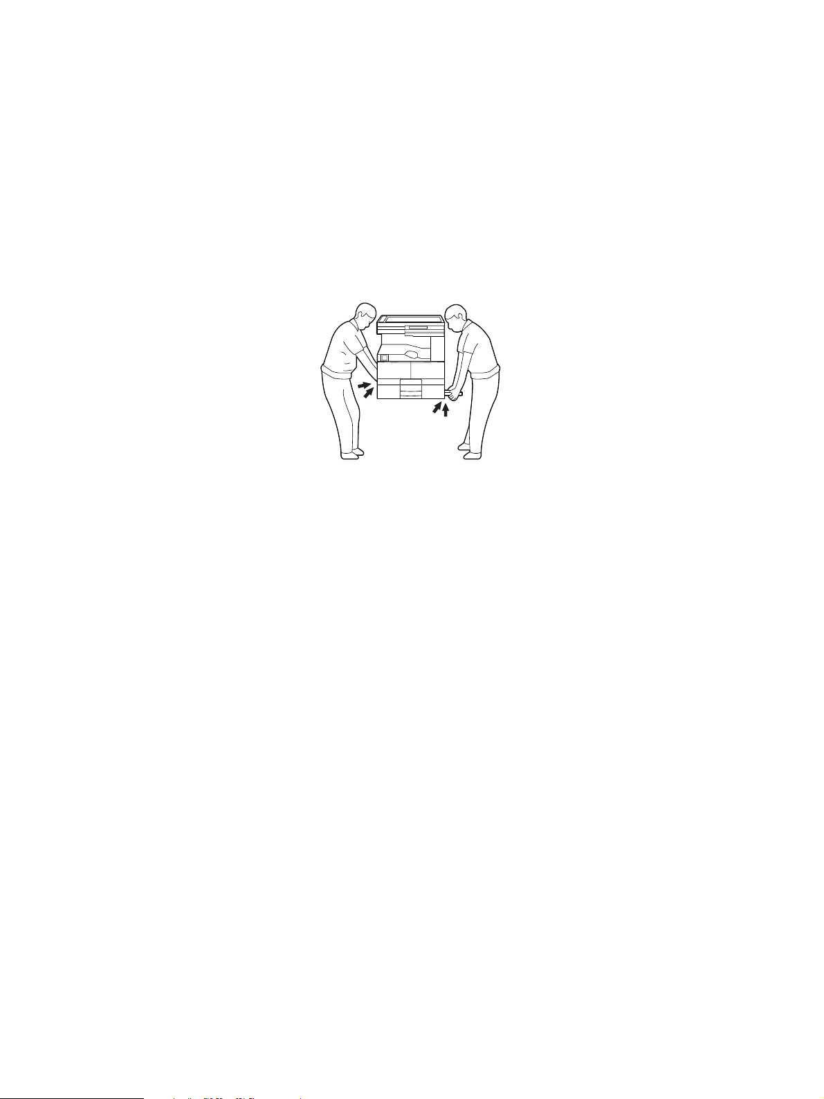
1. Transportation
• When transporting/installing the copier, employ two persons and be sure to use the positions as
indicated below.
The copier is fairly heavy and weighs approximately 50 kg (110 lb), therefore pay full attention
when handling it.
4 portions
2. Installation
• Be sure to use a dedicated outlet with AC 115 or 120V/15A (220V, 230V, 240V/10A) or more for its
power source.
• The copier must be grounded for safety.
Never ground it to a gas pipe or a water pipe.
• Select a suitable place for installation.
Avoid excessive heat, high humidity, dust, vibration and direct sunlight.
• Also provide proper ventilation as the copier emits a slight amount of ozone.
• To insure adequate working space for the copying operation, keep a minimum clearance of 80
cm (32") on the left, 80 cm (32") on the right and 10 cm (4") in the rear.
• After having installed the copier, be sure to push the carrying handles into the copier.
3. Service of Machines
• Basically, be sure to turn the main switch off and unplug the power cord during service.
• Be sure not to touch high-temperature sections such as the exposure lamp, the fuser unit, the
damp heater and their periphery.
• Be sure not to touch high-voltage sections such as the chargers and the high-voltage transformer.
• Be sure not to touch rotating/operating sections such as gears, belts, pulleys, fans, etc.
• When servicing the machines with the main switch turned on, be sure not to touch live sections
and rotating/operating sections. Avoid exposure to laser radiation.
• Use suitable measuring instruments and tools.
December 2002 TOSHIBA TEC e-STUDIO160/200/250 GENERAL PRECAUTIONS

• Avoid exposure to laser radiation during servicing.
– Avoid direct exposure to beam.
– Do not insert tools, parts, etc. that are reflective into the path of the laser beam.
– Remove all watches, rings, bracelets, etc. that are reflective.
4. Main Service Parts for Safety
• The breaker, door switch, fuse, thermostat, thermofuse, thermistor, etc. are particularly important
for safety. Be sure to handle/install them properly.
5. Cautionary Labels
• During servicing, be sure to check the rating plate and the cautionary labels such as “Unplug the
power cord during service”, “Hot area”, “Laser warning label” etc. to see if there is any dirt on their
surface and whether they are properly stuck to the copier.
6. Disposition of Consumable Parts/Packing Materials
• Regarding the recovery and disposal of the copier, supplies, consumable parts and packingm a -
terials, it is recommended to follow the relevant local regulations or rules.
7. When parts are disassembled, reassembly is basically the reverse of disassembly unless otherwise noted in this manual or other related documents. Be
careful not to reassemble small parts such as screws, washers, pins, E-rings,
toothed washers in the wrong places.
8. Basically, the machine should not be operated with any parts removed or disassembled.
9. Precautions Against Static Electricity
• The PC board must be stored in an anti-electrostatic bag and handled carefully using a wristband,
because the ICs on it may become damaged due to static electricity.
Caution: Before using the wrist band, pull out the power cord plug of the copier and make
sure that there is no uninsulated charged objects in the vicinity.
Caution: Dispose of used batteries and RAM-ICs including lithium batteries according to the
manufacturer's instructions.
Attention: Se débarrasser de batteries et RAM-ICs usés y compris les batteries en lithium
selon les instructions du fabricant.
Vorsicht: Entsorgung des gebrauchten Batterien und RAM-ICs (inklusive der Lithium-Batterie)
nach Angaben des Herstellers.
e-STUDIO160/200/250 GENERAL PRECAUTIONS December 2002 TOSHIBA TEC

CONTENTS
1. ADJUSTMENT ITEMS .................................................................................................. 1-1
1.1 Error Code List ................................................................................................................... 1-1
1.2 Self-Diagnosis Modes ........................................................................................................ 1-6
1.2.1 Adjust mode (05) ..................................................................................................... 1-8
1.2.2 System mode ........................................................................................................ 1-13
1.2.3 User test mode...................................................................................................... 1-18
1.2.4 Function test ......................................................................................................... 1-21
1.2.5 MAINTENANCE .................................................................................................... 1-38
1.2.6 SERVICE LIST ...................................................................................................... 1-43
1.2.7 Country/Region code ............................................................................................ 1-49
1.2.8 Scanner parking mode .......................................................................................... 1-50
1.2.9 Speaker volume .................................................................................................... 1-51
1.2.10 Adjustment of document width sensor .................................................................. 1-52
1.3 Image Quality Control ...................................................................................................... 1-53
1.4 Copy Image Dimension Adjustment ................................................................................. 1-54
1.4.1 Adjustment of paper aligning value ....................................................................... 1-55
1.4.2 Printer unit adjustment .......................................................................................... 1-56
1.4.3 Scanner unit adjustment ....................................................................................... 1-61
1.5 Sharpness (HPF) Adjustment .......................................................................................... 1-66
1.6 Gamma Slope Correction................................................................................................. 1-67
1.7 High-Voltage Adjustment .................................................................................................. 1-68
1.7.1 Adjustment ............................................................................................................ 1-68
1.7.2 Precautions ........................................................................................................... 1-71
1.8 Adjusting the Scanner Section ......................................................................................... 1-74
1.8.1 Installing glass ...................................................................................................... 1-74
1.8.2 Installing scanner motor ........................................................................................ 1-76
1.8.3 Adjusting the carriage 1 ........................................................................................ 1-77
1.8.4 Installing carriage 2 ............................................................................................... 1-79
1.8.5 CCD unit ............................................................................................................... 1-82
1.9 Adjusting the main drive gear assembly........................................................................... 1-86
1.10 MAIN PWA replacement procedure ................................................................................. 1-90
1.11 Measurement of Transfer Guide Bias ............................................................................... 1-92
1.12 Adjustment of the doctor-sleeve gap ................................................................................ 1-94
December 2002 TOSHIBA TEC 1 e-STUDIO160/200/250 CONTENTS

2. PREVENTIVE MAINTENANCE (PM) ............................................................................ 2-1
2.1 Maintenance Performed Every 81,000 (e-STUDIO160/200 Series) and
99,000 Copies (e-STUDIO250 Series) ............................................................................... 2-1
2.2 Preventive Maintenance Check List .................................................................................... 2-1
2.3 PM Kit ................................................................................................................................ 2-14
2.4 List of Adjustment Tools .................................................................................................... 2-15
2.5 List of Grease .................................................................................................................... 2-15
3. PRECAUTIONS FOR STORING & HANDLING SUPPLIES ......................................... 3-1
3.1 Precautions for Storing TOSHIBA Supplies ........................................................................ 3-1
3.2 Checking and Cleaning of the Pressure Roller .................................................................. 3-2
3.3 Checking and Cleaning of the Cleaning Roller ................................................................... 3-2
3.4 Checking and Cleaning of the Heat Roller ......................................................................... 3-3
3.5 Checking and Replacing of the Transfer Guide Roller ........................................................ 3-3
3.6 Checking and Cleaning of Photoconductive Drum ............................................................. 3-4
3.7 Checking and Cleaning of Drum Cleaning Blade ............................................................... 3-5
4. TROUBLESHOOTING .................................................................................................. 4-1
4.1 Troubleshooting Based on Error Code ............................................................................... 4-2
4.1.1 Transporting jam in the main body .......................................................................... 4-2
4.1.2 Paper feeding jam ................................................................................................... 4-7
4.1.3 Transporting jam for the optional trays .................................................................. 4-13
4.1.4 Paper jam if some cover is opened ....................................................................... 4-18
4.1.5 Paper transporting jam at the ADF ........................................................................ 4-22
4.1.6 Paper transporting jam at the RADF ..................................................................... 4-24
4.1.7 Paper jam in finisher ............................................................................................. 4-26
4.1.8 Drive system service call ...................................................................................... 4-30
4.1.9 Temporary paper supply mechanism service call ................................................. 4-33
4.1.10 Optical system service call ................................................................................... 4-39
4.1.11 Process system service call .................................................................................. 4-41
4.1.12 Fuser system service call ..................................................................................... 4-41
4.1.13 Communications system service call .................................................................... 4-42
4.1.14 ADF or RADF system service call ......................................................................... 4-44
4.1.15 Other abnormal service call .................................................................................. 4-48
4.1.16 Laser optical system service call .......................................................................... 4-49
4.1.17 Finisher related service call .................................................................................. 4-50
4.1.18 Scanner related service call .................................................................................. 4-55
4.1.19 Printer related service call .................................................................................... 4-56
4.1.20 Fax related service call ......................................................................................... 4-56
4.1.21 OCT system service call ....................................................................................... 4-57
4.1.22 Other service call .................................................................................................. 4-57
4.2 Troubleshooting of Image ................................................................................................. 4-58
e-STUDIO160/200/250 CONTENTS 2 December 2002 TOSHIBA TEC

5. UPDATING THE FIRMWARE ........................................................................................ 5-1
5.1 Outline ................................................................................................................................ 5-1
5.2 Using the Recovery PWA ................................................................................................... 5-2
5.2.1 Using main recovery PWA ...................................................................................... 5-2
5.2.2 Using the scanner recovery PWA ........................................................................... 5-5
5.3 Using the Batch File ........................................................................................................... 5-8
5.3.1 Creating Download Disks ........................................................................................ 5-8
5.3.2 Downloading ......................................................................................................... 5-13
5.4 Using the TOSHIBA Viewer .............................................................................................. 5-20
6. WIRE HARNESS CONNECTION DIAGRAMS ............................................................. 6-1
6.1 AC Wire Harness ............................................................................................................... 6-1
APPENDIX .......................................................................................................................... A-1
Appendix A. Specifications ......................................................................................................... A-1
Appendix B. Accessories ...........................................................................................................A-5
Appendix C. Options .................................................................................................................. A-6
Appendix D. Replacement Units/Supplies .................................................................................. A-6
Appendix E. System List ............................................................................................................ A-7
Appendix F. Power Supply Unit .................................................................................................. A-8
December 2002 TOSHIBA TEC 3 e-STUDIO160/200/250 CONTENTS

1. ADJUSTMENT ITEMS
2. PREVENTIVE MAINTENANCE
(PM)
3. PRECAUTIONS FOR
STORING & HANDLING
SUPPLIES
4. TROUBLESHOOTING
5. UPDATING THE FIRMWARE
6. WIRE HARNESS
CONNECTION DIAGRAMS

1. ADJUSTMENT ITEMS
1.1 Error Code List
While the error message or “Call for service” symbol is flashing, pressing the [CLEAR/STOP] key and
the [8] key on the digital keys at the same time shows one of the following error codes on the copy-
quantity indicator as long as those keys are pressed.
Classification Error code Machine status
Transporting jam in the main
body
Paper feeding jam
Transporting jam for the
optional trays
E01 Paper jam inside the machine
E02 Paper jam near the fuser unit
E03 Paper remaining inside the machine at power on (Except
for ADF/RADF)
E04 to E07 Reserved
E08 Transporting jam inside the ADU
E09 Time out error that occurs at the paper feeding sensor
E10 Reserved
E11 Paper feeding jam at the ADU
E12 Paper feeding jam at the SFB
E13 Cassette 1 feeding jam
E14 Cassette 2 feeding jam (PFU)
E15 Cassette 3 feeding jam (PFP)
E16 Cassette 4 (CM) feeding jam (e-STUDIO200/250 series)
E17 to E18 Reserved
E19 LCF feeding jam (e-STUDIO200/250 series)
E20 to E30 Reserved
E31 Paper not reach to feed sensor from cassette 2, so paper
jam inside the main unit during cassette 2 feed
E32 Paper not reach to feed sensor from cassette 3 or 4, so
paper jam inside the main unit during the feed
E33 Paper not reach to feed sensor from LCF cassette.
(e-STUDIO200/250 series)
E34 Paper not reach to 2nd cassette feed sensor from cas-
sette 3 or 4. (Cassette 4 is e-STUDIO200/250 series)
E35 Paper jam in cassette 4 transport path
(e-STUDIO200/250 series)
E36 Paper jam in LCF transport path
(e-STUDIO200/250 series)
E37 to E40 Reserved
December 2002 TOSHIBA TEC 1 - 1 e-STUDIO160/200/250 ADJUSTMENT ITEMS
Classification Error code Machine status
Paper jam if some cover is
opened
Paper transporting jam at the
ADF or RADF
Paper jam in the finisher
(e-STUDIO200/250 series)
Life end
Other operator calls
E41 Copier front cover or side cover is opened during copying
(Copier front cover, side cover, or transport cover of job
separator/offset tray/bridge cover is opened during
copying)
E42 Side cover of cassette 2 or cassette 3 is opened during
copying
E43 ADU is opened during copying
E44 Reserved
E45 Side cover of LCF is opened during copying
(e-STUDIO200/250 series)
E46 to E70 Reserved
E71 Original feeding jam at the feeding area of the ADF or
RADF
E72 Original transporting jam at the transporting area of the
ADF or RADF
E73 Original exiting jam at the exiting area of the ADF or RADF
E74 Original reversing jam at the reversing area of the RADF
E75 to EA0 Reserved
EA1 Paper transport delay jam
EA2 Paper transport stop jam
EA3 Paper remaining on the finisher transport path at power
ON
EA4 Finisher is opened during copying
EA5 Finisher staple jam
EA6 Finisher early arrival jam
EA7 Set transport jam before stapling
EA8 to EAE Reserved
EAF Stapled set transport jam
EB1 to EZ9 Reserved
- Process unit life nearly end
- Toner is nearly empty
- No toner cartridge
- Toner empty
- No process unit
- Process unit life end
- Upper tray of the job separator is full
- Lower tray of the job separator is full
- Offset tray is full
- Finisher tray is full (e-STUDIO200/250 series)
e-STUDIO160/200/250 ADJUSTMENT ITEMS 1 - 2 December 2002 TOSHIBA TEC
Classification Error code Machine status
Other operator calls
CALL SERVICE from drive
system
Temporary paper supply
mechanism error
- Internal tray full (when finisher bridge installed)
(e-STUDIO200/250 series)
- No paper in the cassette 1
- No paper in the cassette 2
- No paper in the cassette 3
- No paper in the cassette 4 (e-STUDIO200/250 series)
- No paper in the LCF (e-STUDIO200/250 series)
- Cassette 1 is not ready
- Cassette 2 is not ready
- Cassette 3 is not ready
- Cassette 4 is not ready (e-STUDIO200/250 series)
- LCF is not installed (e-STUDIO200/250 series)
Front cover or side cover of the copier is open
Cover of the job separator is open
Cover of the off set catch tray is open
Cover of the bridge cover is open
(e-STUDIO200/250 series)
Cover of the ADU is open
Side cover of the cassette 2 is open
Side cover of the cassette 3 is open
Side cover of the LCF is open
(e-STUDIO200/250 series)
Finisher joint is open (e-STUDIO200/250 series)
No staples (displayed only when stapling is designated)
(e-STUDIO200/250 series)
C01 Main motor drive error
C02 to C03 Reserved
C04 PFP main motor drive error
C05 Reserved
C06 LCF feed motor error (e-STUDIO200/250 series)
C07 to C10 Reserved
C11 to C12 Reserved
C13 Cassette 1 error
C14 Cassette 2 error
C15 Cassette 3 error
C16 Cassette 4 error (e-STUDIO200/250 series)
C17 Reserved
C18 LCF tray error (e-STUDIO200/250 series)
C19 LCF feed motor abnormal (e-STUDIO200/250 series)
C20 Reserved
December 2002 TOSHIBA TEC 1 - 3 e-STUDIO160/200/250 ADJUSTMENT ITEMS
Classification Error code Machine status
CALL SERVICE from the
optical system
CALL SERVICE from the
process system
CALL SERVICE from fuser
area
CALL SERVICE from commu-
nication
C21 Carriage initialization error
C22 to C24 Reserved
C25 Scanner unit watch dog error
C26 Exposure lamp disconnection or peak detection error
C27 to C30 Reserved
C31 to C37 Reserved
C38 Replaced process unit error
C39 to C40 Reserved
C41 Abnormal thermistor or heater disconnection at power ON
C42 Reserved
C43 Warming up mode after disconnection judgment, or ab-
normal thermistor after ready
C44 Warming up mode after disconnection judgment, or heater
abnormal after ready
C45 Thermistor disconnection at the end part of heater
C46 to C50 Reserved
C51 to C55 Reserved
C56 Communication error between PFC and main unit
CALL SERVICE from ADF or
RADF
C57 Communication error between main unit and IPC
(e-STUDIO200/250 series)
C58 Communication error between IPC and finisher
(e-STUDIO200/250 series)
C59 to C70 Reserved
C71 Paper supply motor lock error
C72 Reserved
C73 EE-PROM initialization error
C74 Defective adjustment by the exit/reversal sensor detected
C75 to C80 Reserved
C81 Fan motor lock error
C82 Document aligning lower sensor (RADF)/Aligning sensor
(ADF) adjustment error
C83 Size length adjustment error
C84 to C89 Reserved
e-STUDIO160/200/250 ADJUSTMENT ITEMS 1 - 4 December 2002 TOSHIBA TEC

Classification Error code Machine status
CALL SERVICE from others
CALL SERVICE from laser
optical system
CALL SERVICE from finisher
(e-STUDIO200/250 series)
C90 Reserved
C91 SRAM abnormality (Lithium battery or SRAM chip are
abnormal.)
C92 to C94 Reserved
C95 Power supply unit fan motor abnormality
C96 Process unit fan motor abnormality
C97 Vacuum fan motor abnormality
C98 Clock IC abnormality
C99 PFC microcomputer abnormal
CA1 Polygon motor abnormal
CA2 HSYNC abnormal
CA3 to CB0 Reserved
CB1 Reserved
CB2 Exit motor abnormal
CB3 Reserved
CB4 Reserved
CB5 Staple motor abnormal
CB6 to CC2 Reserved
CC3 Set processing motor abnormal
Reserved
Scanner I/F
FAX unit
Offset catch tray
Reserved
CC4 to CC7 Reserved
CC8 Front aligning motor abnormal
CC9 Upper tray elevator motor abnormal
CCA Lower tray elevator motor abnormal
CCB Rear aligning motor abnormal
CCC to CD0 Reserved
F01 to F10 Reserved
F11 Scanner I/F error
F12 Write error at downloading the scanner unit program
F13 Download sector error of the scanner unit program
F14 Scanner unit F-ROM error
F15 to F20 Reserved
F31 Modem IC does not work normal
F32 to F40 Reserved
F41 Initial detection error of the offset catch tray
F42 to F99 Reserved
December 2002 TOSHIBA TEC 1 - 5 e-STUDIO160/200/250 ADJUSTMENT ITEMS
1.2 Self-Diagnosis Modes
The self-diagnosis functions are used to make the settings for the various PPC functions. This document
describes the self-diagnosis functions.
For the FAX functions, refer to the SERVICE HANDBOOK (GD-1061).
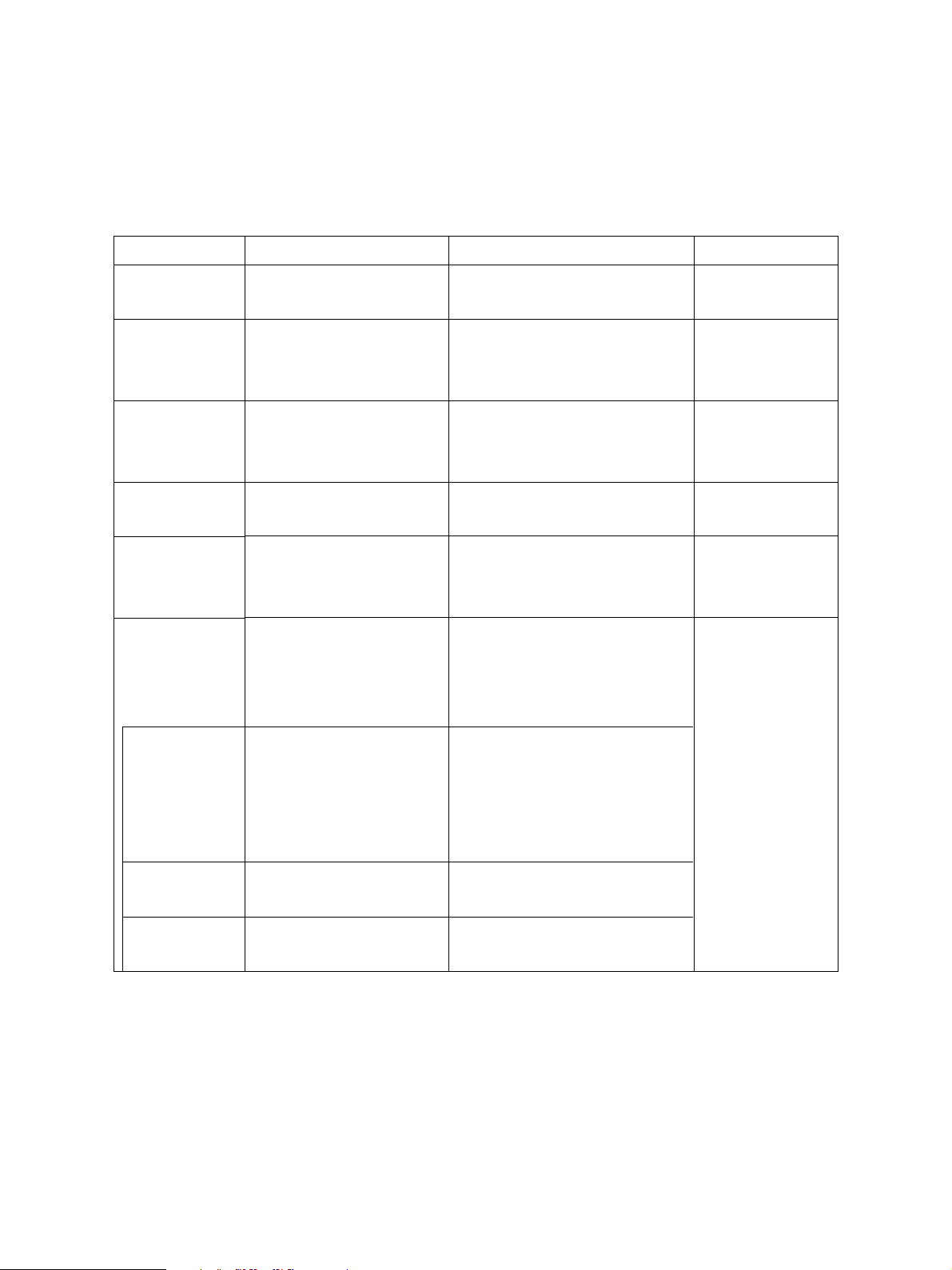
For the method to enter each mode of the self-diagnosis functions, refer to the following chart.
Mode
Country/Region
code
Adjust mode
System mode
Scanner parking
mode
RAM clear
Service mode
How to enter
Turn the power on while
pressing the 0 and 2 keys.
Turn the power on while
pressing the 0 and 5 keys.
Turn the power on while
pressing the 0 and 8 keys.
Turn the power on while
pressing the 0 and 9 keys.
Turn the power on while
pressing the 1, 3, and * keys.
Press the PROGRAM key
*3
while REDAY is indicated,
and then press the *, #, *,
then * keys.
Definition
Selects the country/region code.
Finely adjusts copy image quality.
Confirmation printing enabled by
pressing the INTERRUPT key.
Performs setups for the system,
maintenance, operations, printer,
scanner, etc.
Fixes the scanner carriage in place
when transporting the copier.
Clears values excluding the ones
set in 08-446/447 and in the Ad-
just mode (05).
Performs setups for FUNCTION
TEST and MAINTENANCE, and
prints the Service List.
How to clear
*1
Turn the power off.
Turn the power off.
Turn the power off.
*2
Press the
PROGRAM key,
and then press the
*, #, *, then * keys.
FUNCTION
TEST
MAINTENANCE
Service list
*1: After inputting the country/region code, the copier automatically enters the warm up mode.
*2: After the RAM clear, the machine automatically enters the warm up mode.
*3: In the SERVICE MODE, each function of the FUNCTION TEST, MAINTENANCE, or SERVICE LIST
in each test item of the TEST MODE (displayed by pressing the PROGRAM key), are added. When
the copier enters this mode, these functions are available.
*4 The copier enters into the service mode by pressing 1 and 3 keys while turning the power on. To exit
from the service mode, turn the power off.
After entering the service
mode, select it on the screen.
This mode is selected by
turning the power on while
pressing the 1 and 3 keys.
After entering Service Mode,
select it on the screen.
After entering Service Mode,
select it on the screen.
Conducts OPE. PANEL TEST,
PRINT TEST, MODEM TEST, etc.
Performs setups for Memory Clear,
facsimile function, etc.
Prints PROTOCOL TRACE, Total
Error, FUNCTION LIST, etc.
Or turn the power
off.
Or press the
COPY key, or
press the MAIN
MENU key. *4
e-STUDIO160/200/250 ADJUSTMENT ITEMS 1 - 6 December 2002 TOSHIBA TEC

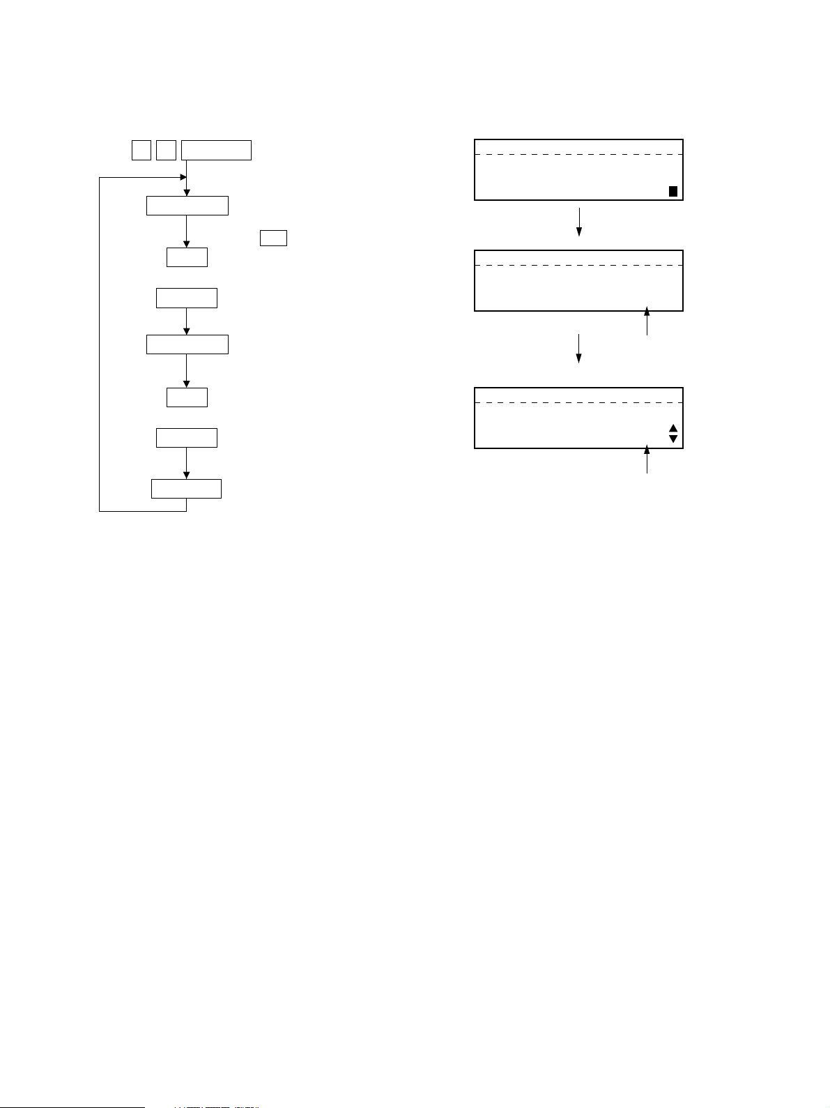
Power ON
"02"
Country/Region
code
Standby
"13*" "05"
RAM clear
"INT""INT"
Test printWarming up
"INT" : INTERRUPT key on.
Quick reference chart for self-diagnostic mode
"08" "13" "09"
System modeAdjust mode
Function test
Power OFF
Scanner parking mode
01-02-01
Note: Power ON Turn on the power switch.
Power OFF Turn on the power switch.
INT Press the INTERRUPT key.
C/S Press the CLEAR/STOP key.
Menu map
The menu below can be selected by pressing the program key. (However, the menu in the broken-dotted
box are displayed only when the copier enters the SERVICE MODE.)
01. DEFAULT SETTINGS
02. LISTS
03. INITIAL SETUP
04. MENU LIST
05. TEST MODE
01. AUTO TEST
02. INDIVIDUAL TEST
03. TEST RESULT LIST
04. FUNCTION TEST
05. MAINTENANCE
06. SERVICE LIST
Service mode
01. OPE PANEL TEST
02. PRINT TEST
01. MEMORY CLEAR
02. SET FUNCTION
01. PROTOCOL TRACE
02. TOTAL ERRORS
01-02-02
December 2002 TOSHIBA TEC 1 - 7 e-STUDIO160/200/250 ADJUSTMENT ITEMS
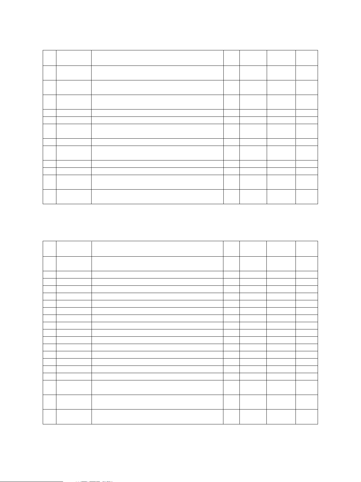
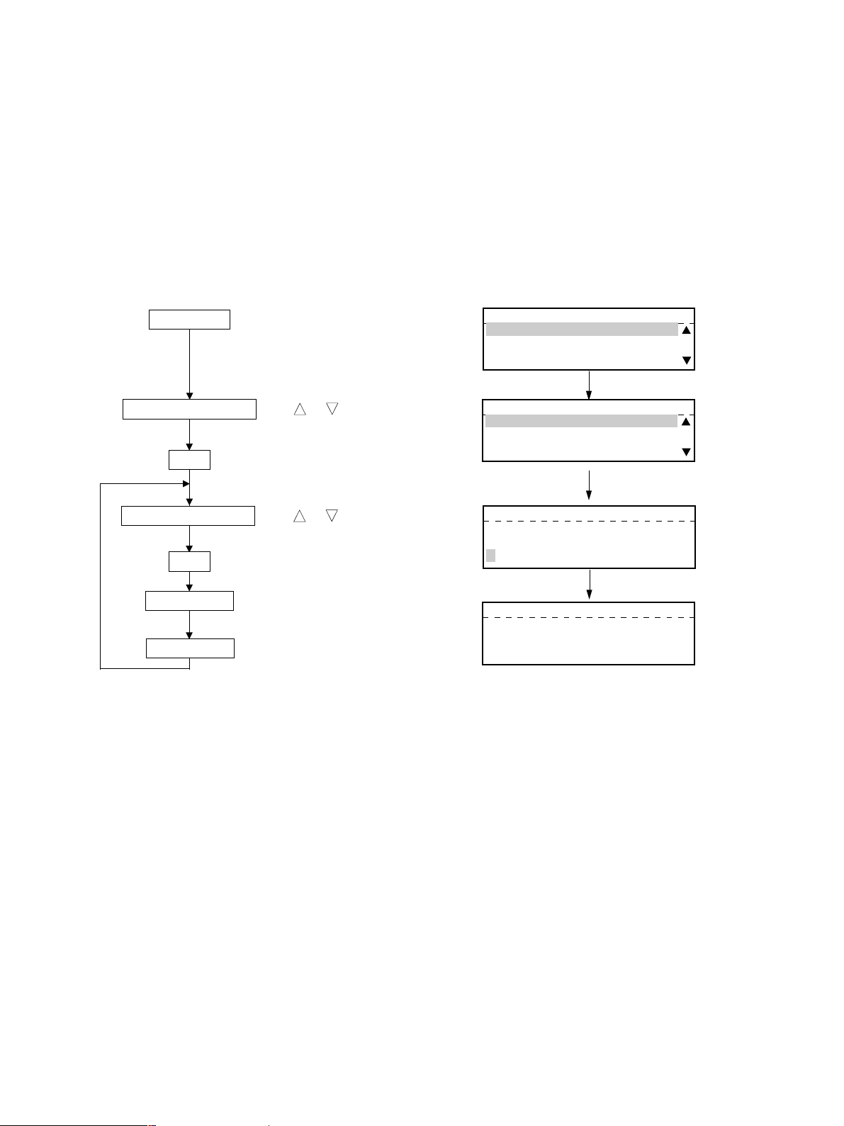
1.2.1 Adjust mode (05)
<Key used in operation> <Display messages>
0 5
Digital Keys
SET
or
START
Digital Keys
SET
or
START
Cancel
Power ON
Enter code
( C/S used to correct value)
Adjustment value
TEST MODE A
MC=
TEST MODE A
MC=
205
Enter code
TEST MODE A
MC=205
DT= 156
Adjustment value
e-STUDIO160/200/250 ADJUSTMENT ITEMS 1 - 8 December 2002 TOSHIBA TEC

ADJUST MODE (05) ITEMS
Process unit adjustment
Code
205
210
220
221
233
234
235
261
Factor
Development
Charging
Transfer
Transfer
Separation
Separation
Separation
Laser
Adjustment item (05)
Developer bias DC adjustment
• Increment/decrement by U/D (Up/Down) key
• Real-time high voltage output
• Developer bias DC ON
Grid voltage initial value adjustment
• Increment/decrement by U/D key
• Real-time high voltage output (Charge ON)
Transfer transformer DC output High adjustment
• Increment/decrement by U/D key
• Real-time high voltage output (Transfer High ON)
Transfer transformer DC output Center adjustment
• Increment/decrement by U/D key
• Real-time high voltage output (Transfer Center ON)
Separation output High adjustment
• Increment/decrement by U/D key
• Real-time high voltage output (Separation-High ON)
Separation output Center adjustment
• Increment/decrement by U/D key
• Real-time high voltage output (Separation-Center ON)
Separation output Low adjustment
• Increment/decrement by U/D key
• Real-time high voltage output (Separation-Low ON)
Laser power 600 DPI Initial value adjustment
• Increment/decrement by U/D key
• No polygon rotation
• Real-time laser output
(Results of automatic laser adjustment)
(Laser ON)
Mode
ALL
ALL
ALL
ALL
ALL
ALL
ALL
ALL
Default
156
(166)
104
(118)
180
142
(155)
67
49
35
39
(53)
Acceptable
Guaranteed
*1
*1
*1
value
0-255
0-255
value
0-223
0-255
0-255
0-255
0-255
0-255
0-255
Refer to
page
1-70
1-70
1-70
1-70
1-70
1-70
1-70
*1 : The value in parentheses is for the model e-STUDIO200/250 series.
December 2002 TOSHIBA TEC 1 - 9 e-STUDIO160/200/250 ADJUSTMENT ITEMS
Scanning adjustment
Code
304
305
306
354
355
356
357
358
365
366
380
381
Factor
Scanner
mechanism
Scanner
mechanism
Scanner
mechanism
R/ADF
RADF
R/ADF
R/ADF
R/ADF
R/ADF
RADF
ADF
ADF
Adjustment item (05)
Scanner feed magnification 0.1 %/step
Scanner feed misalignment 0.126 mm/step
(600 DPI)
CCD scanning misalignment 0.04233 mm/step
R/ADF aligning amount (surface) 0.5 mm/step
RADF aligning amount (back) 0.5 mm/step
ADF position sensor adjustment or RADF sensor automatic
adjustment
R/ADF transport speed fine adjustment 0.1 %/step
R/ADF horizontal misalignment adjustment
0.04233 mm/step
RADF top position adjustment (surface) 0.1 mm/step
RADF top position adjustment (back) 0.1 mm/step
ADF document width sensor adjustment, narrowest document
guide width
ADF document width sensor adjustment, widest document
guide width
*1 : The entry of code enables automatic adjustment.
Mode
ALL
ALL
ALL
ALL
ALL
ALL
ALL
ALL
ALL
ALL
ALL
ALL
Default
128
128
128
10
10
-
50
128
50
50
-
-
Acceptable
value
0-255
85-171
5-251
0-20
0-20
0-100
0-255
0-100
0-100
*1
*1
*1
Refer to
page
1-62
1-63
1-61
1-52
1-52
Printer adjustment
Code
400
410
417
418
419
421
430
431
432
433
440
441
442
443
444
445
450
451
452
Factor
Printer system
Printer system
Printer system
Printer system
Printer system
Printer system
Printer system
Printer system
Printer system
Printer system
Printer system
Printer system
Printer system
Printer system
Printer system
Printer system
Printer system
Printer system
Printer system
Adjustment item
Polygon motor speed fine adjustment 600 DPI
0.2%/step
Laser start position 600 DPI Cassette 1
Laser start position 600 DPI Cassette 2
Laser start position 600 DPI Cassette 3/LCF
Laser start position 600 DPI Cassette 4
Main motor speed fine adjustment Approx. 0.1%/step
Top margin 0.7 mm/step
Left margin 0.1 mm/step
Right margin 0.1 mm/step
Bottom margin 0.1 mm/step
Top position Cassette 1 0.4 mm/step
Top position Cassette 2 0.4 mm/step
Top position Bypass (SFB) 0.4 mm/step
Top position LCF 0.4 mm/step
Top position PFP 0.4 mm/step
Top position ADU 0.4 mm/step
Aligning amount Copier cassette (Cassette 1)
Long size (0.52 mm/step) Paper length of min. 259 mm
Aligning amount Copier cassette (Cassette 1)
Short size (0.52 mm/step) Paper length of max. 258 mm
Aligning amount Cassette 2 (PFU)
Long size (0.52 mm/step) Paper length of min. 322 mm
Mode
PPC
PPC
PPC
PPC
PPC
PPC
PPC
PPC
PPC
PPC
ALL
ALL
ALL
ALL
ALL
ALL
ALL
ALL
ALL
Default
128
108
106
119
128
124 (130)
0
0
0
0
23
7
8
8
7
8
14
14
22
Acceptable
Value
108-148
0-255
0-255
0-255
0-255
78-178
0-30
0-255
0-255
0-255
0-40
0-15
0-15
0-15
0-15
0-15
0-31
0-31
0-31
Refer to
page
1-56
1-57
1-57
1-57
1-57
1-58
1-64
1-64
1-65
1-65
1-59
1-59
1-59
1-59
1-59
1-59
1-55
1-55
1-55
*1 : The value in parentheses is for the model e-STUDIO200/250 series.
e-STUDIO160/200/250 ADJUSTMENT ITEMS 1 - 10 December 2002 TOSHIBA TEC

Printer adjustment
Code
453
455
456
457
458
463
465
497
Factor
Printer system
Printer system
Printer system
Printer system
Printer system
Printer system
Printer system
Printer system
Adjustment item
Aligning amount Cassette 2 (PFU)
Short size (0.52 mm/step) Paper length of max. 321 mm
Aligning amount ADU
(e-STUDIO160: 0.7 mm/step, e-STUDIO200/250: 0.47 mm/step)
Aligning amount PFP Short size (0.52 mm/step)
Paper length of max. 321 mm
Aligning amount LCF 0.52 mm/step
Aligning amount Bypass (SFB) Short size (0.52 mm/step )
Paper length of max. 258 mm
Aligning amount PFP Long size (0.52 mm/step)
Paper length of min. 322 mm
Aligning amount Bypass Long size (0.52 m/step)
Paper length of min. 259 mm
Laser start position 600 DPI Bypass
Scan image processing parameter 600 DPI
Code
501
503
504
505
506
507
508
509
510
512
514
515
593
594
595
Factor
Density
Density
Density
Density
Density
Density
Density
Density
Density
Density
Density
Density
Density
Density
Density
Manual density fine adjustment Center
value
Ditto
Ditto
Manual density fine adjustment Light step
value
Ditto
Ditto
Manual density fine adjustment Dark step
value
Ditto
Ditto
Auto density fine adjustment
Ditto
Ditto
ϒ data inclination correction
ϒ data inclination correction
ϒ data inclination correction
Adjustment item
Mode
ALL
ALL
ALL
ALL
ALL
ALL
ALL
PPC
*1 : The value in parentheses is for the model e-STUDIO200/250 series.
Image
mode
PPC
PPC
PPC
PPC
PPC
PPC
PPC
PPC
PPC
PPC
PPC
PPC
PPC
PPC
PPC
Image
quality
mode
Photo
Text/Photo
Text
Text/Photo
Photo
Text
Text/Photo
Photo
Text
Photo
Text/Photo
Text
Text/Photo
Photo
Text
Default
139
133
130
28
18
20
13
20
18
140
133
130
0
0
0
Default
16
26
(23) *1
16
16
21
18
28
101
Acceptable
L ← V → D
L ← V → D
L ← V → D
L ← V → D
L ← V → D
L ← V → D
Acceptable
value *1
0-255
0-255
0-255
0-255
V → L
0-255
V → L
0-255
V → L
0-255
V → D
0-255
V → D
0-255
V → D
0-255
0-255
0-255
0-9
0-9
0-9
Value
0-31
0-31
0-31
0-31
0-31
0-31
0-31
0-255
Refer to
page
1-55
1-55
1-55
1-55
1-55
1-55
1-55
1-57
Refer to
page
1-53
1-53
1-53
1-53
1-53
1-53
1-53
1-53
1-53
1-53
1-53
1-53
1-67
1-67
1-67
*1 L: Light, V: Value, D: Dark
December 2002 TOSHIBA TEC 1 - 11 e-STUDIO160/200/250 ADJUSTMENT ITEMS
Scan image processing parameter 600 DPI
Code
620
621
622
693
694
695
Factor
Image
quality
Image
quality
Image
quality
Density
Adjustment item
No. of units: HPF table number
0: Use of default value
1: Text/Photo mode
2: Photo mode
3: For Text mode
4 - 9: Unused
No. of tens: Filter combination intensity
0: Use of default value
1 - 9: Filter combination intensity
Ditto
Ditto
Range correction on original set on the
ADF or RADF.
Set whether the value of the background
peak and text peak are fixed or not.
If they are fixed, the range correction is
performed with standard values.
The values of the background peak and
text peak affect the reproduction of the
background density and text density re-
spectively.
The number of units: Data while automatic
density is selected.
The number of tens: Data while manual
density is selected.
Background peak Text peak
1: fixed fixed
2: varied fixed
3: fixed varied
4: varied varied
Image
mode
PPC
PPC
PPC
PPC
Image
quality
mode
Text/Photo
Photo
Text
Text/Photo
Photo
Text
Default
1
2
3
12
12
44
Acceptable
value *1
0-99
The larger the intensity
coefficient the stronger the
intensity.
0-99
0-99
11-14
21-24
31-34
41-44
Refer to
page
1-66
1-66
1-66
e-STUDIO160/200/250 ADJUSTMENT ITEMS 1 - 12 December 2002 TOSHIBA TEC

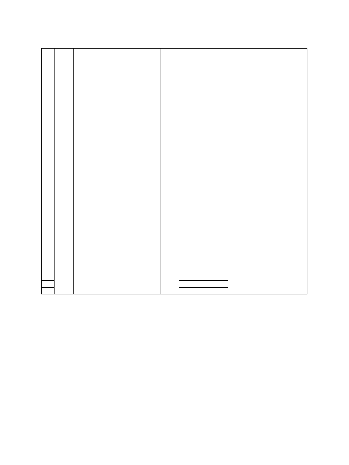
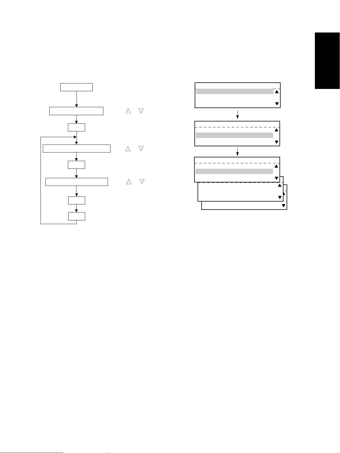
1.2.2 System mode
<Key used in operation> <Display messages>
0 8
Digital Keys
SET
or
START
Digital Keys
SET
or
START
Cancel
Power ON
Enter code
( C/S used to correct value)
Setting value
TEST MODE D
MC=
TEST MODE D
MC=
204
Enter code
TEST MODE D
MC=204
DT= 1
Setting value
SYSTEM MODE (08) ITEMS
Code
202
204
205
206
207
Factor
SYS
SYS
SYS
SYS
SYS
Selection of external counter
0: No external counter
1: With coil controller
2: Non-standard: With copylizer/key
3: With key counter
Auto clear [sec]
0: Invalid 1: 15s 2: 30s 3: 45s 4: 60s
5: 75s 6: 90s 7: 105s 8: 120s
9: 135s 10: 150s 11: 180s 12: 210s
13: 240s 14: 270s 15: 300s
Auto low power 0: Invalid 1: Valid
(Time is set on panel.)
Auto sleep 0: Invalid 1: Valid
(Time is set on panel.)
Display for key counter setting
0: Set key copy counter
1: ASK CASHIER TO SWITCH ON
* Valid when 08-202 is set to 3 (With key
counter).
Setting item
card
Mode
ALL
ALL
ALL
ALL
ALL
Image
quality
mode
Default
0
3
1
1
0
*1 : The entry of code enables automatic execution.
Acceptable
value *1
0-3
0-15
0-1
0-1
0-1
Refer to
page
December 2002 TOSHIBA TEC 1 - 13 e-STUDIO160/200/250 ADJUSTMENT ITEMS
SYSTEM MODE (08) ITEMS
Code
224
225
226
227
228
246
250
251
252
255
256
300
340
351
352
355
374
Factor
SYS
SYS
SYS
SYS
SYS
SYS
MAINT
MAINT
MAINT
MAINT
MAINT
OPE.
MAINT
COUNT
COUNT
COUNT
COUNT
Setting item
SFB paper size
0: A3 (8K) 1: A4 (16K) 2: A4R (16KR)
3: A5R 4: B4 5: B5 6: B5R
7: LETTER 8: LETTER-R
9: LEDGER 10: LEGAL
11: STATEMENT-R 12: COMPUTER
13: FOLIO 14: Undefined
15-17: Reserved
Copier cassette paper size
0: A3 (8K) 1: A4 (16K) 2: A4R (16KR)
3: A5R 4: B4 5: B5 6: B5R
7: LETTER 8: LETTER-R 9: LEDGER
10: LEGAL 11: STATEMENT-R
12: COMPUTER 13: FOLIO
14: Reserved 15: Reserved
Cassette 2 paper size (Same as 08-225)
Cassette 3 paper size (Same as 08-225)
(e-STUDIO200/250 series)
Cassette 4 paper size (Same as 08-225)
(e-STUDIO200/250 series)
Clearing copy jobs at auto clear
0: No clearing 1: Clearing
Service personnel telephone number
PM counter setting value
PM counter present value
08-251: Operates when other than 0
Object of 08-352
PFP installation status
0: Auto (Automatically changed to 1
or 2 by observing the PFC cassette
installation status.)
1: PFP (Cassette 3)
2: PFP (Cassette 3,4)
(e-STUDIO200/250 series)
3: Reserved 4: None
LCF paper size
0: A4 1: LT 2: Reserved
MAX . 9
0: 999
1: 99
2: 9
Drum end counter setting value.
Display of total counter data
(Confirmed by listing and changed by
memory writing)
A3/LD double count
0: Single count 1: Double count
Display of drum lite counter
ADF/RADF scan counter
Mode
ALL
ALL
ALL
ALL
ALL
ALL
ALL
ALL
ALL
ALL
ALL
ALL
Image
quality
mode
Default
14
NAD: 7
Acceptable
value *1
0-14
0-13
Other: 1
NAD: 7
0-13
Other: 1
NAD: 7
0-13
Other: 1
NAD: 7
0-13
Other: 1
0
0-1
20 digits
Own M/C registration area
NAD:
e-STUDIO160/
200: 81000
e-STUDIO250:
99000
Othre: 0
0
0
NAD: 1
0-999999
0-999999
0-4
0-2
Other: 0
0
e-STUDIO160/
200: 27000
e-STUDIO250:
33000
0-2
0-99999
(0: Not displayed)
Display only
1
0
0-1
Display only
0-999999
*1 : The entry of code enables automatic execution.
Refer to
page
e-STUDIO160/200/250 ADJUSTMENT ITEMS 1 - 14 December 2002 TOSHIBA TEC
Code
375
376
377
385
386
388
389
400
401
402
403
404
406
407
408
Factor
COUNT
COUNT
COUNT
COUNT
COUNT
COUNT
COUNT
Process
Process
Process
Process
Process
Process
Process
Process
Setting item
COPY job (print) counter
PRINTER job (print) counter
FAX job (print) counter
Total counter in scanner unit (display)
Platen scan count
LOAD instruction for total counter when
replacing the main PWA Scanner unit →
Copier
SAVE instruction for total counter when
replacing the scanner unit Copier → Scanner unit
Thermistor heater status counter
0: No error occurrence
1: C41 1st thermistor or heater error
when starting W-UP
2: C41 2nd thermistor or heater error
when starting W-UP
3: Reserved
4: C43 Thermistor error during W-UP
5: C44 Heater error during W-UP
6: C43 Thermistor error after ready
7: C44 Heater error after ready
8: C45 Heater end thermistor error af-
ter ready (High temperature)
9: C44 High temperature heater error
10: C45 Heater end thermistor error af-
ter ready (Low temperature)
Drum life counter
Power on hours counter
(7-digit display: Hour 5-digit, minute 2digit)
Total power ON hours
Fuser counter
Always double count for A3, B4, LD, LG,
COM, A4R, LTR, and FOLIO
Developer material counter.
Always double count for A3, B4, LD, LG,
COM, A4R, LTR, and FOLIO.
Clear by installing a new PU.
Pre-run start time
0: Invalid 1: 30 sec 2: 35 sec
3: 40 sec 4: 45 sec 5: 50 sec
6: 55 sec 7: 60 sec
Pre-run operation time
0: Invalid 1: 5 sec 2: 10 sec
3: 15 sec 4: 20 sec 5: 25 sec
6: 30 sec 7: 40 sec 8: 50 sec
9: 60 sec 10: 150 sec
Pre-run operation time for thick paper
0: Invalid 1: 1 sec 2: 2 sec 3: 3 sec
4: 4 sec 5: 5 sec 6: 6 sec 7: 7 sec
8: 8 sec 9: 9 sec 10: 10 sec
11: 12 sec 12: 14 sec 13: 16 sec
14: 18 sec 15: 20 sec
Mode
ALL
ALL
ALL
ALL
ALL
ALL
ALL
ALL
ALL
ALL
ALL
Image
quality
mode
Default
0
0
0
0
0
0
0
(2)
*1
10
*1 : The entry of code enables automatic execution.
Acceptable
value *1
Double counted if printing
A3 or LD size paper
Double counted if printing
A3 or LD size paper
Double counted if printing
A3 or LD size paper
0-999999
0-999999
*1
*1
0-10
0-999999
0-9999959
Counter area added
0-999999
Counter area added
0-999999
Counter area added
0-7
0-10
0-15
Refer to
page
1-90
December 2002 TOSHIBA TEC 1 - 15 e-STUDIO160/200/250 ADJUSTMENT ITEMS

Code
410
411
412
413
446
*2
447
*2
462
480
481
483
486
503
504
550
603
604
611
614
Factor
Process
Process
Process
Process
Process
Process
PRINT
PRINT
PRINT
PRINT
Image
processing
F/W
Image
processing
F/W
F/W
F/W
F/W
Setting item
Fixing temperature when printing
4: 170°C 5: 175°C 6: 180°C 7: 185°C
8: 190°C 9: 195°C 10: 200°C
11: 205°C 12: 210°C 13: 215°C
Fixing temperature when ready
0: 170°C 1: 175°C 2: 180°C 3: 185°C
4: 190°C 5: 195°C 6: 200°C
7: Drop control ON
Fixing temperature in low power state
0: OFF 1: 120°C 2: 130°C 3: 140°C
4: 150°C 5: 160°C
Fixing temperature for thick paper
0: Invalid 1: 195°C 2: 200°C 3: 205°C
4: 210°C
Correction for transfer output ON timing.
(0: -110 ms -----18: +70 ms)
Correction for transfer output OFF timing.
(0: +110 ms -----18: -70 ms)
Setting for switchback operation to copy
mixed-size originals form RADF
0: Invalid 1: Valid
Cassette priority selection
0: A4/LT 1: LCF 2: Cassette 1
3: Cassette 2 4: Cassette 3
5: Cassette 4
Auto cassette change
0: None 1: Normal
Polygon motor preceding start-up setting
0: Valid (DF, platen) 1: Invalid
2: DF only
Time for suspension of the Polygonal motor pre-running
(0: 15 sec, 1: 30 sec, 2: 45 sec)
Density default in image quality mode
0: AUTO 1: Light 3 2: Light 2
3: Light 1 4: Center 5: Dark 1
6: Dark 2 7: Dark 3
Also reflected on panel.
Special paper selection
0: FOLIO/B size
1: 13" LEGAL (South America only)
2: K size (China only)
Image mode default
0: Standard 1: Photo 2: Text
Auto duplex mode (when document is
loaded into DF)
0: Invalid 1: Simplex/Duplex
2: Duplex/Duplex
APS priority selection
0: APS 1: AMS 2: None (100%)
3: Reserved
Book duplex document selection
0: Left-hand open 1: Right-hand open
The function clear LED blinks. Blinks when
the value is different from the present default value after copying (until auto clear
or all clear.)
0: Invalid (Always off) 1: Valid
*1 : The value in parentheses is for the model e-STUDIO200/250 series.
*2 : This value should be adjusted at the factory. Do not change the value in
Mode
ALL
Image
quality
mode
Default
8
Acceptable
value *1
4-13
Refer to
page
(10)
*1
ALL
ALL
7
NAD: 5
0-7
0-5
Other: 4
(NAD: 3)
(Other: 2) *1
ALL
0
0-4
(2)
*1
ALL
11
0-18
1-91
10 ms/step
ALL
ALL
ALL
ALL
ALL
PPC
PPC
PPC
PPC
PPC
PPC
PPC
ALL
ALL
1
(11) *1
0
0
1
0
0
0
0
0
0
0
0
1
0-18
10 ms/step
0-1
0-5
0-1
0-2
0-2
0-8
0-2
0-2
0-2
0-3
0-1
0-1
1-91
the field. When the main PWA is replaced, it should be entered again.
e-STUDIO160/200/250 ADJUSTMENT ITEMS 1 - 16 December 2002 TOSHIBA TEC

Code
618
620
635
641
642
648
649
650
652
665
673
685
688
Factor
F/W
F/W
F/W
F/W
F/W
F/W
F/W
F/W
F/W
Setting item
Default setting for mixed size originals
0: OFF
1: ON
* Setting 08-618 to 1 (ON) and 08-641 to
4 (alternate) simultaneously is not allowed.
APS forced start (Exclude RADF)
0: Valid (One time pressing)
1: Reserved
2: Invalid
Process for last page (one-sided original)
at duplex copying
0: One-side copy
1: Double-sided copy (blank paper is
added to as the last even numbered
page to output the copy in the same
orientation with previous pages.)
Auto sort mode (when document is loaded
into DF)
Also set on panel.
0: Invalid 1: Staple 2: Sort 3: Invalid
4: Vertical and horizon. alternate
5: Sort offset
* Setting 08-641 to 4 (alternate) and 08-
618 to 1 (ON) simultaneously is not al-
lowed.
Sorter mode priority selection (at all clear)
Also set on panel.
0: NON SORT 1: STAPLE 2: SORT
3: Reseved 4: ALTERNATION
5: SORT OFFSET
6: NON SORT OFFSET
Initialization of finisher bin at all clear
0: Valid 1: Invalid
Magazine sort setting
0: Left-hand open 1: Right-hand open
2in1/4in1 setting
0: Horizontal write 1: Vertical write
Cascade operation setting
(e-STUDIO200/250 series)
0: No cascade
1: 1 → 2 (Endless stack included)
2. Reserved
Set PPC area default.
05: Adjust area, γ adjust store area
08: Setting (PPC-FUNC) area
(Except the counter values)
Resetting drum-related counters,
08-355, 08-401.
(Valid when 08-689 is set to 1.)
Paper feeding by turns at duplex copying
0: Invalid 1: Valid
UI shortcut key
0: Invalid
1: Valid (REDUCE/ENLARGE and ZOOM
UP/DOWN only)
2: Valid (Cassette paper size setting only)
3: Valid (All, REDUCE/ENLARGE, ZOOM
UP/DOWN, and cassette paper size
setting)
Mode
PPC
Memory
PPC
PPC
PPC
PPC
ALL
Expansion
PPC
Expansion
PPC
Expansion
PPC
Self-
check
Self-
check
PPC
PPC
Image
quality
mode
Default
0
0
0
2
0
0
0
0
1
Acceptable
value *1
0-1
0-2
0-1
0-5
0-6
0, 1
0-1
0-1
0-2
*1
1
1
0-1
0-4
*1 : The entry of code enables automatic execution.
Refer to
page
1-90
December 2002 TOSHIBA TEC 1 - 17 e-STUDIO160/200/250 ADJUSTMENT ITEMS
1.2.3 User test mode
When you press the PROGRAM key and enter the TEST mode from the menu, the items that can be
tested by the user are displayed.
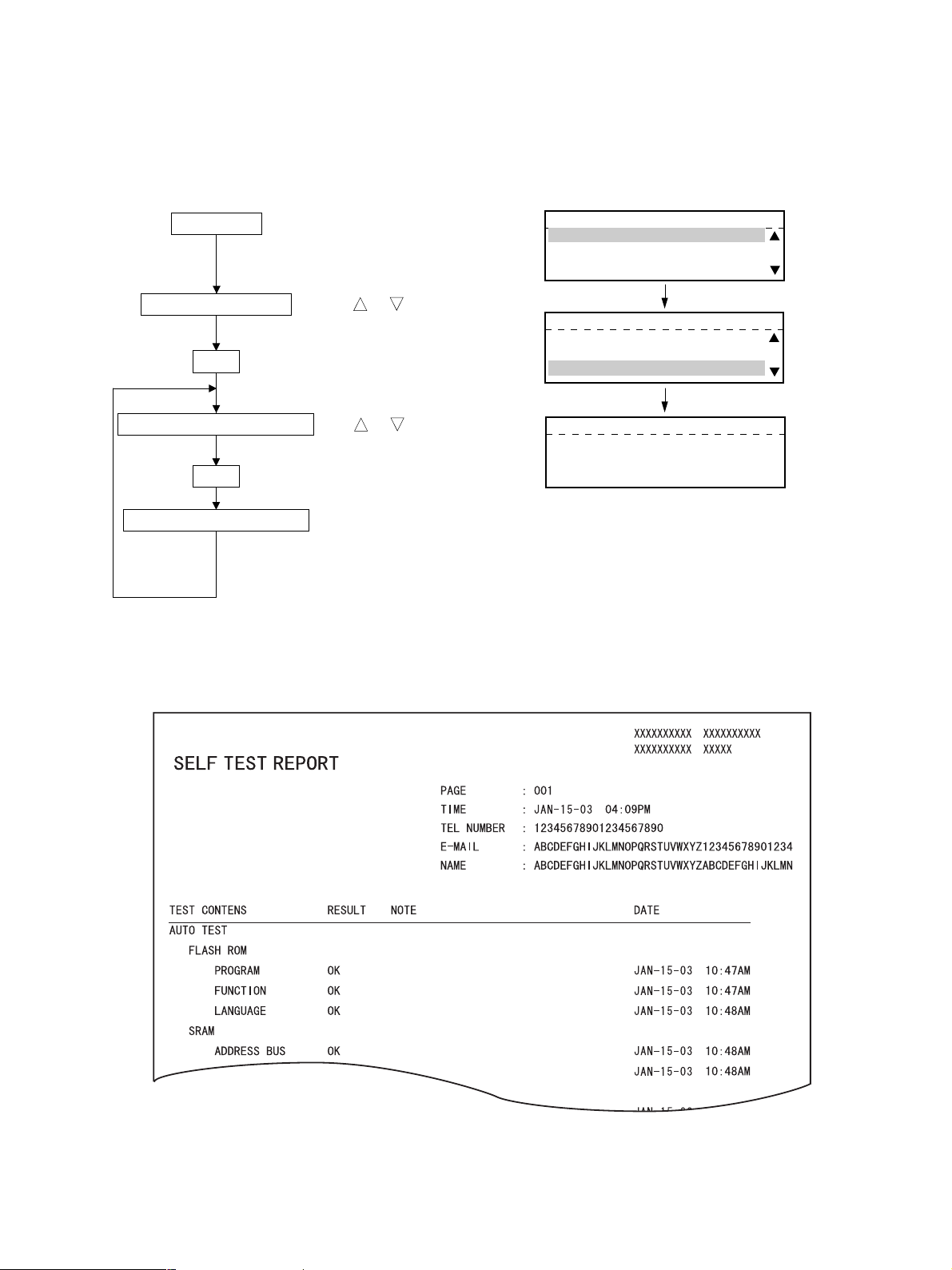
(1) AUTO TEST
This mode allows the user to independently diagnose the machine by automatically performing a
series of tests.
<Key used in operation> <Display messages>
PROGRAM
Press the PROGRAM key
PROGRAM
01.DEFAURT SETTINGS
02.LISTS
03.INITIAL SETUP
Select TEST MODE
Use or keys
TEST MODE
01.AUTO TEST
02.INDIVIDUAL TEST
SET
Select AUTO TEST
SET
Auto test run
End of TEST
Test Items
a) Flash ROM test Calculates and compares the check sums of the firmware, function data and
Use or keys
It takes about 2 minutes to
finish TEST
03.TEST RESULT LIST
AUTO TEST
-------------------
AUTO TEST
Completed
language information with the previously stored corresponding check sum
values.
b) SRAM test Same as Function Test.
c) DRAM test Same as Function Test.
d) MODEM test Same as Function Test.
e) SCANNER test Same as Function Test.
f) CODEC test Same as Function Test.
g) Printer test Checks each part of the printer (fan, HVPS, polygon, heater, LSU) and prints
one page of test pattern (not performed when there is no paper).
h) Phonebook data test Calculates and compares the check sum of the phonebook with the previ-
ously stored check sum value.
i) Network board test (with GF-1110)
e-STUDIO160/200/250 ADJUSTMENT ITEMS 1 - 18 December 2002 TOSHIBA TEC
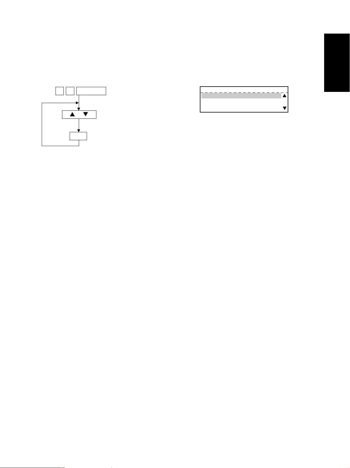
(2) INDIVIDUAL TEST
The user can perform a test in interactive mode and locate the faulty point from the test result. The test
result is printed in the form of a report.
<Key used in operation> <Display messages>
PROGRAM
Press the PROGRAM key
PROGRAM
01.DEFAURT SETTINGS
02.LISTS
03.INITIAL SETUP
Select TEST MODE
SET
Use or keys
TEST MODE
01.AUTO TEST
02.INDIVIDUAL TEST
03.TEST RESULT LIST
Select INDIVIDUAL TEST
Use or keys
INDIVIDUAL TEST
SET
01.ADF TEST
02.KEY TEST
03.LED LIST
Select item to be tested
SET
CIS
Test Items
a) ADF test Transports and ejects originals to check the transport system. Transports
Use or keys
Selected test is performed
TEST MODE
04.LCD TEST
TEST MODE
05.SPEAKER TEST
06.SWITCH TEST
07.TEST PRINT
and ejects a certain number of originals and displays the number of the
originals. The tester checks that this value matches the number of the origi-
nals. A transport speed can be selected with the resolution key.
b) Key test Press all the keys on the operation panel to check if they are detected nor-
mally. The key test ends when the STOP key is pressed in the end. If there is
any key which is not detected when pressed before the STOP key is pressed,
it will be judged to be an error.
c) LED test When the test is performed, all the LEDs will come on. If there is any LED
which is not lit when visually checked, it will be judged to be an error.
d) LCD test All the dots on the display go off (turn black). When the Start key is then
pressed, all the dots light (turn white). If there is any dot which does not light
or go off when visually checked, it will be judged to be an error.
e) Speaker test Check that the volume level from the speaker changes.
f) Sensor test Sensor test.
Open and close the covers by following the guidance appearing on the dis-
play.
g) Printer test Checks the printer function by printing two test patterns.
December 2002 TOSHIBA TEC 1 - 19 e-STUDIO160/200/250 ADJUSTMENT ITEMS
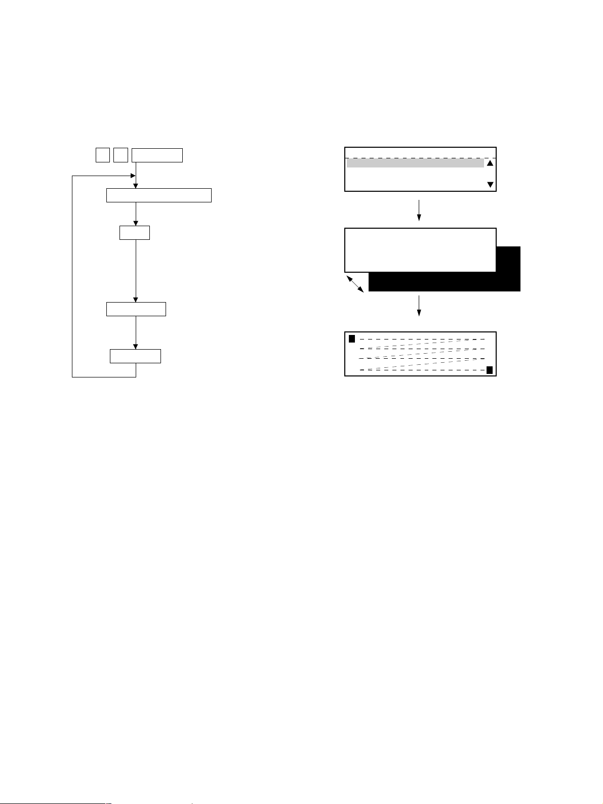
(3) TEST RESULT LIST
Prints the results of (1) AUTO TEST and (2) INDIVIDUAL TEST.
<Key used in operation> <Display messages>
PROGRAM
Press the PROGRAM key
PROGRAM
01.DEFAURT SETTINGS
02.LISTS
03.INITIAL SETUP
Select TEST MODE
Use or keys
TEST MODE
01.AUTO TEST
SET
Select TEST RESULT LIST
SET
Print TEST RESULT LIST
If there is any NG in the RESULT column, the corresponding test is problematic. An test with an
asterisk (*) cannot be executed unless the corresponding option is installed.
Use or keys
02.INDIVIDUAL TEST
03.TEST RESULT LIST
TEST RESULT LIST
Printing accepted
e-STUDIO160/200/250 ADJUSTMENT ITEMS 1 - 20 December 2002 TOSHIBA TEC
1.2.4 Function test
The function test checks each function of the copier. To enter the function test mode, follow the procedure
below, or enter the Service mode (*,#,*,*) and select the menu for the function test
<Key used in operation> <Display messages>
1 3
Power ON
FUNCTION TEST
01.OPE.PANEL TEST
02.PRINT TEST
03.MODEM TEST
or
SET
The following tests can be conducted in the Function test mode.
01. OPE. PANEL TEST
02. PRINT TEST
03. MODEM TEST *1 (Factory test)
04. SENSOR TEST
05. SRAM TEST
06. DRAM TEST
07. CLOCK IC TEST
Select test menu
08. SCANNER TEST
09. CODEC TEST
10. OUTPUT TEST
11. PRINTER BOARD TEST *2
*1: When the FAX kit (GD-1061) is not installed, the test is not present.
*2: When the PCL kit (GA-1031) is not installed, the test is not present.
December 2002 TOSHIBA TEC 1 - 21 e-STUDIO160/200/250 ADJUSTMENT ITEMS
(1) 01. OPE PANEL TEST
This test checks the control panel display. When any key other than START and CLEAR/STOP is pressed
during the display test, O and X are displayed alternately in the lower right of the display.
<Key used in operation> <Display messages>
1 3
Power ON
01.OPE. PANEL TEST
SET
START
Cancel
All display dots keep turning on
and off alternatery for one second
each. (All LEDs turn on.)
The cursor moves (from the
upper left to the lower right).
FUNCTION TEST
01.OPE.PANEL TEST
02.PRINT TEST
03.MODEM TEST
Select test menu
e-STUDIO160/200/250 ADJUSTMENT ITEMS 1 - 22 December 2002 TOSHIBA TEC

(2) 02. PRINT TEST
The test pattern is printed when a number is entered according to the displayed instructions
<Key used in operation> <Display messages>
1 3
02.PRINT TEST
Power ON
Digital Keys
SET
Digital Keys
SET
Digital Keys
SET
Digital Keys
SET
START
C/S
Select test menu
Enter print code
Select paper cassette (C)
Print setup 1 (T)
Print setup 2 (B)
*1
FUNCTION TEST
01.OPE.PANEL TEST
02.PRINT TEST
03.MODEM TEST
PRINT TEST
P=
115
Print code
115
C=1
T=128
B=100
C = Paper cassette selection
T = Print setup 1
B = Print setup 2
C
0: Stack feed bypass (SFB)
1: 1st cassette
2: 2nd cassette (PFU)
3: 3rd cassette (PFP/LCF)
4: 4th cassette
T
Character density 0 to 255 panel setting.
B
Background density 0 to 255 panel setting.
Some codes do not have T or B.
*1: Be sure to press this key after printing starts.
(If this key is not pressed, the copier keeps printing)
December 2002 TOSHIBA TEC 1 - 23 e-STUDIO160/200/250 ADJUSTMENT ITEMS

TEST PRINT (02) ITEMS
Code
109
Electrical
110
Electrical
111
Image processing
112
Electrical
113
Image processing
114
Electrical
115
Electrical
116
Electrical
121
Image processing
122
Image processing
123
Image processing
124
Image processing
135
Image processing
136
Image processing
137
Image processing
138
Image processing
141
Image processing
142
Image processing
Factor
Test pattern item
All-surface halftone (latter part) Error diffusion
Halftone density 0 to 255 panel setting
Scanning 256 levels (latter part) Error diffusion
Scanning 33 levels (latter part) Error diffusion
Scanning 17 levels (latter part) Error diffusion
Feed 33 levels (latter part) Error diffusion
Feed 17 levels (latter part) Error diffusion
Scanning 1 dot line (latter part) 2-level
Character density 0 to 255 panel setting
Background density 0 to 255 panel setting
Scanning 24 dot line (latter part) 2-level
Character density 0 to 255 panel setting
Background density 0 to 255 panel setting
All-surface halftone (foregoing part) Error diffusion
Scanning 256 levels (foregoing part) Error diffusion
Scanning 33 levels (foregoing part) Error diffusion
Scanning 16 levels (foregoing part) Error diffusion
All-surface horizontal 1 dot line, horizontal 1 dot space
All-surface vertical 1 dot line, vertical 1 dots pace
All-surface horizontal 2 dot line, horizontal 2 dot space
All-surface vertical 2 dot line, vertical 2 dot space
1 dot grid pattern (10 mm pitch)
2 dot grid pattern (10 mm pitch)
Item to be confirmed
All completely black at T=0.
All completely white at T=255.
The density should change
smoothly between black and white.
There should be 33 levels in a tran-
sition between black and white.
There should be 17 levels in a tran-
sition between black and white.
There should be 33 levels in a tran-
sition between black and white.
There should be 17 level in a transi-
tion between black and white.
Black when both T and B are 0.
White when both T and B are 255.
Black when both T and B are 0.
White when both T and B are 255.
All completely gray.
The density should change
smoothly between black and white.
There should be 33 levels in a tran-
sition between black and white.
There should be 16 levels in a tran-
sition between black and white.
Grid of 10 by 10 mm square. The
line width increases as the code increases (141→142→145→146).
Test 142 is used for 1.4 Adjustment.
145
Image processing
146
Image processing
149
Image processing
150
Image processing
151
Image processing
e-STUDIO160/200/250 ADJUSTMENT ITEMS 1 - 24 December 2002 TOSHIBA TEC
Grid pattern of 4 sets of 1 dot line, horizontal 2 dots space
(10 mm pitch)
Grid pattern of 4 sets of 2 dot line, horizontal 2 dots space
(10 mm pitch)
A3 all completely black
A3 all white
Rightward rising slant line 1 dot (5 mm pitch)
All completely black
All completely white
The line interval in the main scan-
ning direction should be 5 mm. The
line should be straight.

(3) 03. MODEM TEST (Factory test)
Refer to the Service Handbook (GD-1061).
(4) 04. SENSOR TEST
When the machine enters the SENSOR TEST Mode, the status of each sensor is indicated on the display.
The status can be checked by selecting the corresponding bit.
(For items to be checked, refer to the Sensor Test Items table.)
<Key used in operation> <Display messages>
1 3
Power ON
04.SENSOR TEST
SET
or
Cancel
<Display messages>
Select test menu
Display selection
1 (A1)
01001010 00100010 00000001
A
01001010 00100010 00000001
I
01001110 00100000 00000001
00001010 00100110
FUNCTION TEST
02.PRINT TEST
03.MODEM TEST
04.SENSOR TEST
BIT
7------0
11 (I8)
12 (S1)
01001010 00100010
S
01001110 00100000
01001110 00100000 00000001
P
00001010 00100110
20 (P5)
December 2002 TOSHIBA TEC 1 - 25 e-STUDIO160/200/250 ADJUSTMENT ITEMS

• Explanation of status display
When the sensor test is carried out, the status
of each sensor is indicated on the display with
0 or 1.
Each signal is divided into 8-bit blocks.
The character on the left edge of the display
indicates as follows:
A: Signal input to ASIC
I: Signal input to the IO port
S: Signal from the scanner or R/ADF
P: Signal from the option connected to the
PFC
The display is switched using the or key.
Example 1:
Confirm whether the front cover is open or close.
The front cover is equipped with the 24-V ON/OFF
switch (Interlock switch) and the front cover switch.
The status of both switches is 1 when the cover is
open, and 0 when it is close.
When the status of the one is 0 and that of the other
is 1 as shown in the example, there is something
wrong with either of these switches.
Status display example
A
I
A1
IO1
IO4
IO7
S
S1
S3
P
P1
P4
01001010 00100010 00000001
A
01001010 00100010 00000001
I
A2
IO2
IO5
IO8
S2
S4
P2
P5
IO3 Bit1
A3
IO3
IO6
P3
01001110 00100000 00000001
00001010 00100110
IO4 Bit2
Front cover
Open Close
IO3 bit 1 (Interlock switch) 1 0
IO4 bit 2 (Front cover switch) 1 0
e-STUDIO160/200/250 ADJUSTMENT ITEMS 1 - 26 December 2002 TOSHIBA TEC

Example 2:
Confirm whether or not the optional memory PWA
is installed, with the status of bits 6 and 7 of IO1 on
the display.
Memory expansion slot on the back of the copier
As shown in the table below, bits 6 and 7 detect the
upper slot and lower slot, respectively.
The installation of the memory PWA can be con-
firmed with these bits.
PWA Bit 7 Bit 6
Not inserted (upper and lower slots) 1 1
Inserted into the upper slot 1 0
Inserted into the lower slot 0 1
Inserted into both slots 0 0
(1: No PWA inserted / 0: PWA inserted)
The capacity of memory installed can be confirmed,
with bits 4 and 5 of IO1.
Bit 6 (MEM1)
Bit 7 (MEM2)
IO1
Bit7
A
I
IO1
Bit6
01001010 00100010 00000001
01001010 00100010 00000001
Slot (upper)
Slot (lower)
01001110 00100000 00000001
00001010 00100110
December 2002 TOSHIBA TEC 1 - 27 e-STUDIO160/200/250 ADJUSTMENT ITEMS

SENSOR TEST (04) ITEMS
Data
1 (A1)
ASIC1
A/D
CH0
2 (A2)
ASIC1
A/D
CH2
3 (A3)
ASIC1
A/D
CH3
4 (IO1)
I/O
E0100C
5 (IO2)
I/O
E01006
Bit
7
A/D CH0 b7
6
A/D CH0 b6
5
A/D CH0 b5
4
A/D CH0 b4
3
A/D CH0 b3
2
A/D CH0 b2
1
A/D CH0 b1
0
A/D CH0 b0
7
A/D CH2 b7
6
A/D CH2 b6
5
A/D CH2 b5
4
A/D CH2 b4
3
A/D CH2 b3
2
A/D CH2 b2
1
A/D CH2 b1
0
A/D CH2 b0
7
A/D CH3 b7
6
A/D CH3 b6
5
A/D CH3 b5
4
A/D CH3 b4
3
A/D CH3 b3
2
A/D CH3 b2
1
A/D CH3 b1
0
A/D CH3 b0
7
MEM2DET
6
MEM1DET
5
SDRAM2ID
4
SDRAM1ID
3
PCLSET
2
AU1SET
1
DRUM
0
FUSE
7
6
5
4
3
2
1
0
FAXDET
Input info.
-
-
-
-
-
-
-
Function
Fusing thermistor A/D value
The value for temperature data is expressed with 8 bits.
Fusing side thermistor A/D value
The value for temperature data is expressed with 8 bits.
Drum thermistor A/D value
The value for temperature data is expressed with 8 bits.
Option MEM2 connection signal
(PWA-F-MEM Optional memory PWA)
Option MEM1 connection signal
(PWA-F-MEM Optional memory PWA)
Detection signal for MEM PWA2 256 M bit SDRAM
Detection signal for MEM PWA1 256 M bit SDRAM
PCL PWA connection detection signal
I-FAX PWA connection detection signal
Presence or absence detection of process unit
Detection of new or old process unit
-
-
-
Reserved
Reserved
Reserved
Reserved
FAX PWA (GD-1061) connection signal
Value
00H-FFH
00H-FFH
00H-FFH
0: Connected
1: Not connected
0: Connected
1: Not connected
0: 256 M bit
1: 64 M bit/128 M bit
0: 256 M bit
1: 64 M bit/128 M bit
0: Connected
1: Not connected
0: Connected
1: Not connected
0: Without 1: With
0: Normal 1: New
-
-
-
-
-
-
-
0: Connected
1: Not connected
e-STUDIO160/200/250 ADJUSTMENT ITEMS 1 - 28 December 2002 TOSHIBA TEC

Data
6 (IO3)
I/O
E01008
7 (IO4)
I/O
E0100A
8 (IO5)
I/O
E02006
9 (IO6)
I/O
E02008
Bit
7
6
5
4
BUCS
3
FDS2ON
2
FDS1ON
1
24VONOFF
0
COS1ON
7
IPCDET
6
PCDET
5
4
5ROMSEL
3
PSS3
2
FCOSON
1
PESON
0
LPSON
7
6
5
4
JCONECT
3
2
FSELECT
1
0
7
TESTMON
6
PMSTS
5
JPASSW
4
JJAMSW
3
JCOSON
2
JPOSON
1
JFLS2ON
0
JFLS1ON
Input info.
-
-
-
-
-
-
-
-
-
-
Function
Reserved
Reserved
Reserved
Battery abnormal condition detection signal
EXT-SEN (Exit sensor)
FED-SEN (Feed sensor)
Cover open (Interlock SW) detection
TC-SW (Toner cartridge switch) *1
IPC PWA (Finisher) connection signal
PC-I/F PWA connection signal
-
RCVROM (MAIN recovery PWA) installation detection
CST-SW (Paper cassette switch)
FRCOV-SW (Front cover switch) *1
PE-SEN (Paper empty sensor) Cassette 1
T-UP-SEN (Tray-up sensor) Cassette 1
-
-
-
Connection of any of JSP or OCT
Reserved
Connection of BRIDGE COVER
-
Reserved
TNRE-SEN (Toner empty sensor)
Polygon motor synchronizing signal
Connection of OCT
Jam detection/jam detection/middle jam detection
*2
JSP cover open/OCT cover open/BRIDGE COVER cover
open *2
Paper in upper stacker/-/BRIDGE COVER exit jam
detection *2
Upper stacker paper full/offset initial position/-
*2
Lower stacker/paper full/paper full
*2
Value
-
-
-
0: Normal
1: Battery abnormal condition
0: No paper
1: Paper detected
0: Paper detected
1: No paper
0: Closed 1: Open
0: With 1: Without
0: Connected
1: Not connected
0: Connected
1: Not connected
-
0: RCVROM installed
1: Not installed
0: Closed 1: Open
0: Closed 1: Open
0: Paper loaded
1: Paper empty
0: Not lifted up 1: Lifted up
-
-
-
0: Connected
1: Not connected
-
0: BRIDGE COVER connected
1: JSP or OCT
-
-
0: Toner empty
1: Toner detected
0: Synchronous
1: Asynchronous
0: OCT connected
1: BRIDGE COVER or JSP
0: No paper 1: Paper present (JSP/OCT)
0: No paper
1: Paper present (BRIDGE COVER)
0: Cover closed
1: Cover open
0: No paper 1: Paper detected (JSP/OCT)
0: Paper detected
1: No paper (BRIDGE COVER)
0: Normal/non-initial
1: paper full/initial position
0: Normal 1: Paper full (JSP/OCT)
0: Paper full 1: Normal (BRIDGE COVER)
*1: The detection of the presence or absence of a toner cartridge is correctly displayed only when the front
cover is open.
*2: One of the three options is indicated (only one of them can be connect).
December 2002 TOSHIBA TEC 1 - 29 e-STUDIO160/200/250 ADJUSTMENT ITEMS

Data
10 (IO7)
I/O
E0200A
11 (IO8)
I/O
E50000
Low order
8 bits
12 (S1)
Scanner sensor
status 1
Upper 8 bits
13 (S2)
Scanner sensor
status 1
Low order
8 bits
14 (S3)
Scanner sensor
status 2
Upper order
8 bits
Bit
7
6
5
4
3
2
1
0
7
6
5
4
3
2
1
0
7
6
5
4
3
2
1
0
7
6
5
4
3
2
1
0
7
6
5
4
3
2
1
0
Input info.
-
-
-
-
16MBDET
-
MMSYNC
G/PCHK
CTR-CNT
ENABLE
MCONECT
MPSS3ON
MPSS2ON
MPSS1ON
MPSS0ON
MPESON
Function
Reserved
Reserved
Reserved
Reserved
Pix SDRAM 16MB/32MB recognition signal
Reserved
Main motor synchronization
Distinction between GDI and PCL
Counter connection signal
Enable signal
SFB unit connection signal
SFB paper size sensor 3 ON signal
SFB paper size sensor 2 ON signal
SFB paper size sensor 1 ON signal
SFB paper size sensor 0 ON signal
SET-SEN (SFB feed sensor)
HOME-SEN (Home position sensor)
Reserved
Reserved
ADF: ADFCOV-SW (ADF top cover open switch)
RADF: JAM-SW (Jam access cover switch)
SIZE-SEN (Document length sensor)
ADF: ADFOPN-SEN (ADF open sensor)
RADF: RADF-OPN-SNS (RADF open/close sensor)
ADF: EMPTY-SEN (Document empty sensor)
RADF: EMP-SNS (Empty sensor)
ORCOV-SEN (Original cover sensor)
Reserved
LENG-SNS (Original length sensor)
TRY-SNS (Tray sensor)
READ-SNS (Read sensor)
RVR-SNS (Reverse sensor)
ADF: REGST-SEN (ADF registration sensor)
RADF: REG-SNS (Registration sensor)
POS-SEN (ADF read sensor)
ADF: HAISI-SEN (ADF exit sensor)
RADF: EXIT-SNS (Exit sensor)
Reserved
APS-6 (Automatic paper size detection sensor)
APS-5 (Automatic paper size detection sensor)
APS-4 (Automatic paper size detection sensor)
APS-3 (Automatic paper size detection sensor)
APS-2 (Automatic paper size detection sensor)
APS-1 (Automatic paper size detection sensor)
Reserved
Value
-
-
-
-
0: 32 MB 1: 16 MB
-
0: Synchronous (constant speed)
1: Asynchronous
0: PCL 1: GDI
0: Connected
1: Not connected
0: Copy limited 1: Enable
0: Connected
1: Not connected
0: ON 1: OFF
0: ON 1: OFF
0: ON 1: OFF
0: ON 1: OFF
0: Paper present
1: Paper empty
0: Not HP 1: HP
0: Closed 1: Open
0: No paper
1: Paper detected
0: Closed 1: Open
0: Paper empty
1: Paper detected
0: Closed 1: Open
0: No paper 1: Paper present
0: No paper 1: Paper present
0: No paper 1: Paper present
0: No paper 1: Paper present
0: No paper 1: Paper present
0: No paper 1: Paper present
0: No paper 1: Paper present
0: No paper 1: Paper present
0: No paper 1: Paper present
0: No paper 1: Paper present
0: No paper 1: Paper present
0: No paper 1: Paper present
0: No paper 1: Paper present
e-STUDIO160/200/250 ADJUSTMENT ITEMS 1 - 30 December 2002 TOSHIBA TEC

Data
15 (S4)
Scanner sensor
status 2
Low order
8 bits
16 (P1)
PFC
Input check 1
17 (P2)
PFC
Input check 2
18 (P3)
PFC
Input check 3
Bit
7
6
5
4
3
2
1
0
7
SIZPFU
6
5
4
3
PFUFD-SW
2
PFUCOV
1
PFUEMP
Input info.
-
-
-
Reserved
SIZE-SNS 3 (Original width sensor 3)
SIZE-SNS 2 (Original width sensor 2)
SIZE-SNS 1 (Original width sensor 1)
Reserved
Reserved
Reserved
Reserved
2CST-SW (PFU Cassette switch)
Reserved
Reserved
Reserved
OCF-SEN (2nd feed sensor)
2COV-SW (PFU cover open switch)
2PE-SEN (PFU paper empty sensor)
Function
Value
0: No paper 1: Paper present
0: No paper 1: Paper present
0: No paper 1: Paper present
-
-
-
-
0: Installed 1: Not installed
-
-
-
0: No paper 1: Paper present
0: Closed 1: Open
0: Paper loaded
1: Paper empty
0
PFUUP
7
SIZCU
LCTRBTM
6
-
CFENCL0
*1
5
-
SIZLC
4
FEDU
-
3
-
-
2
COV-SW
-
1
PEMPU
-
0
TUPU
-
7
SIZCL
LMTBCKF
6
-
LMTFWDK
*1
5
-
LCEMPFD
4
FEDL
LCSIDCOV
3
PLL-OK
LCMOTLD
2
-
LCTRTOP
1
PEMPL
LCRLYSW
0
TUPL
LCEMP
2T-UP-SEN (PFU tray-up sensor)
CST-U-SW (Upper cassette detection switch)
TRY-BTH-SNR (Tray bottom sensor)
Reserved
PR-MST-SS (Standby side paper mis-staking sensor)
Reserved
Cassette detection switch (LCF)
FED-U-SNR (Upper feed sensor)
Reserved
Reserved
Reserved
SIDE-COV-SW (Side cover open/close switch)
Reserved
EMP-U-SNR (Upper cassette paper empty sensor)
Reserved
TOP-U-SNR (Upper cassette tray-up sensor)
PST-SNR-FS (Feeding side paper stock sensor)
LST-L-SW (Lower cassette detection switch)
EMD-F-HP-SNR (End fence home position sensor)
Reserved
END-F-STP-SNR (End fence stop position sensor)
Reserved
EMP-SNR-SS (Standby side empty sensor)
FED-L-SNR (Lower feed sensor)
Side cover open/close switch (LCF)
PLL lock signal
LCF transport motor
Reserved
TOP-SNR (Tray-up sensor)
EMP-L-SNR (Lower cassette paper empty sensor)
FED-SNR (Feed sensor)
TOP-L-SNR (Lower cassette tray-up sensor)
EMP-SNR-FS (Feeding side empty sensor)
0: Not lifted up 1: Lifted up
0: Installed 1: Not installed
0: Other 1: Lower limit
-
0: OFF 1: Closed
-
0: Installed 1: Not installed
0: No paper 1: Paper loaded
-
-
-
0: Closed 1: Open
-
0: Paper loaded 1: No paper
-
0: Not lifted up 1: Lifted up
-
0: Installed 1: Not installed
0: Other 1: Fence back limit
-
0: OFF 1: Fence forward limit
-
0: OFF 1: Open
0: No paper 1: Paper loaded
0: Open 1: Closed
0: Stable 1: Other
0: Operating 1: Motor stopped
-
0: Other 1: Upper limit
0: Paper loaded 1: No paper
0: Paper detected 1: No paper
0: Not lifted up 1: Lifted up
0: No paper 1: Paper present
*1: The upper value for each bit indicates the function assumed when the PFP is installed, and the lower value
the function assumed when the LCF is installed.
December 2002 TOSHIBA TEC 1 - 31 e-STUDIO160/200/250 ADJUSTMENT ITEMS

Data
19 (P4)
PFC
Input check 4
20 (P5)
PFC
Input check 5
Bit
7
6
5
4
3
2
1
0
7
6
5
4
3
2
1
0
Input info.
-
-
-
-
EXIT-SW
PSTP-1
24VCHK
ADCNT
-
LCFCNT
-
PFPCNT
Function
PFU connection signal
Reserved
Reserved
Reserved
ADUCOV-SW (ADU cover open switch)
FED2-SEN (ADU paper jam sensor (Upper))
FED1-SEN (ADU paper jam sensor (Lower))
Reserved
EXT-SEN (Exit sensor)
FED-SEN (Feed sensor)
24V down signal
ADU connection signal
Reserved
LCF connection signal
Reserved
PFP connection signal
Value
0: Connected
1: Not connected
-
-
-
0: Closed 1: Open
0: No paper 1: Paper present
0: No paper 1: Paper present
0: No paper 1: Paper present
0: Paper present
1: No paper
0: Down 1: Normal
0: Connected
1: Not connected
-
0: Connected
1: Not connected
-
0: Connected
1: Not connected
e-STUDIO160/200/250 ADJUSTMENT ITEMS 1 - 32 December 2002 TOSHIBA TEC

(5) 05. SRAM TEST
The read/write test is performed throughout the image memory. The test checks the whole SRAM. When
an error is found, the address of the erroneous portion is displayed and the test is stopped.
<Key used in operation> <Display messages>
1 3
Power ON
FUNCTION TEST
03.MODEM TEST
04.SENSOR TEST
05.SRAM TEST
05.SRAM TEST
Select test menu
SRAM TEST
SET
TESTING
Cancel
SRAM TEST
OK
or
SRAM TEST
NG
ADDRESS=
BFA106H
(6) 06. DRAM TEST
The read/write test is performed on the DRAM (including page memory and image memory). When an
error is found, the address of the erroneous portion is displayed and the test is stopped.
<Key used in operation> <Display messages>
1 3
Power ON
FUNCTION TEST
04.SENSOR TEST
05.SRAM TEST
06.DRAM TEST
06.DRAM TEST
Select test menu
DRAM TEST
SET
TESTING
Cancel
DRAM TEST
OK
or
DRAM TEST
NG
ADDRESS=
FFE201H
December 2002 TOSHIBA TEC 1 - 33 e-STUDIO160/200/250 ADJUSTMENT ITEMS

(7) 07. CLOCK IC TEST
After programming the fixed data and time on the clock IC, the test reads the programmed data and time
and checks whether or not they are correct
<Key used in operation> <Display messages>
1 3
Power ON
FUNCTION TEST
05.SRAM TEST
06.DRAM TEST
07.CLOCK IC TEST
07.CLOCK IC TEST
Select test menu
CLOCK IC TEST
SET
Cancel
OK
CLOCK IC TEST
NG
(8) 08. SCANNER TEST
The read/write test is performed on the RAM built in the image processing LSI.
<Key used in operation> <Display messages>
or
1 3
Power ON
08.SCANNER TEST
SET
Cancel
FUNCTION TEST
06.DRAM TEST
07.CLOCK IC TEST
08.SCANNER TEST
Select test menu
SCANNER TEST
OK
or
SCANNER TEST
NG
e-STUDIO160/200/250 ADJUSTMENT ITEMS 1 - 34 December 2002 TOSHIBA TEC

(9) 09. CODEC TEST
The test encodes data of 10 lines using the MH coding, decodes it and compares it with the original data.
<Key used in operation> <Display messages>
1 3
Power ON
FUNCTION TEST
07.CLOCK IC TEST
08.SCANNER TEST
09.CODEC TEST
09.CODEC TEST
Select test menu
CODEC TEST
SET
Cancel
OK
or
CODEC TEST
NG
(10) 10. OUTPUT TEST
This test checks the operation of the motor, clutch and fan separately.
This test can check the operations of two or more parts at the same time. For example, the motor is tuned
on while the clutch is on.
<Key used in operation> <Display messages>
Cancel
1 3
Power ON
10.OUTPUT TEST
SET
Digital Keys
SET
START
C/S
Cancel
Select test menu
Enter test mode
Test start
Test stop
FUNCTION TEST
08.SCANNER TEST
09.CODEC TEST
10.OUTPUT TEST
OUTPUT TEST
C=
101
Test code
OUTPUT TEST
C=101
OFF
Turn on or off by pressing
START or C/S, respectively.
December 2002 TOSHIBA TEC 1 - 35 e-STUDIO160/200/250 ADJUSTMENT ITEMS

OUTPUT TEST (10) ITEMS
Code Compo. Operation Note
101 Copier Main motor ON (discharge also ON)/OFF
102 Copier Toner motor ON/OFF
103 Copier Polygon motor ON ( 600 DPI)/OFF
105 Copier Polygon motor ON ( 16*15.4)/OFF
106 Copier Polygon motor ON ( 15.4*16)/OFF
108 Copier Registration roller clutch ON/OFF
109 PFC PFP main motor ON/OFF
201 Copier Pickup clutch ON/OFF
202 PFC PFU pickup clutch ON/OFF
203 PFC 2nd feed clutch ON/OFF
204 Copier Bypass feed clutch ON/OFF
205 PFC LCF feed clutch
206 PFC LCF transport clutch
222 PFC ADU motor (Lower) ON/OFF
223 PFC ADU motor (Upper) forward ON/OFF
224 PFC ADU motor (Upper) reverse ON/OFF
225 PFC PFP transfer clutch ON/OFF
226 PFC Cassette 3 feed clutch ON/OFF
227 PFC Cassette 4 feed clutch ON/OFF
242 Copier Cassette 1 tray-up motor ON
243 PFC Cassette 2 tary-up motor ON
250 Copier Developer bias transformer ON/OFF
251 Copier Charging ON/OFF
255 Copier Transfer guide bias ON/OFF (Do it after having done ON
256 Copier Laser ON/OFF
261 Scanner Scanner carriage motor ON (automatic stop at limit)
263 Scanner Exposure lamp ON/OFF
268 PFC LCF end fence motor ON (right and left)
269 PFC LCF end fence solenoid ON/OFF
270 PFC LCF transport motor ON/OFF
271 PFC LCF tray-up motor up/down
275 PFC Cassette 3 tary-up motor ON
276 PFC Cassette 4 tary-up motor ON
281 RADF RADF pick-up roller rotation ON/OFF (F MOT)
282 RADF RADF registration roller rotation ON/OFF (F MOT)
283 RADF RADF read roller CW rotation ON/OFF (RDMOT)
284 RADF RADF read roller CCW rotation ON/OFF (RDMOT)
285 RADF RADF reverse roller CW rotation ON/OFF (RVMOT)
286 RADF RADF reverse roller CCW rotation ON/OFF (RVMOT)
287 RADF RADF document reverse solenoid ON/OFF
288 RADF RADF exit solenoid ON/OFF
296 ADF ADF transport motor forward ON/OFF
297 ADF ADF transport motor reverse ON/OFF
298 RADF RADF fan motor ON/OFF
of the output of Code 250)
e-STUDIO160/200/250 ADJUSTMENT ITEMS 1 - 36 December 2002 TOSHIBA TEC

Code Compo. Operation Note
302 Copier Transfer DC-ON-HIGH (05-220 value used)
303 Copier Transfer DC-ON-CENTER (05-221 value used)
304 Copier Transfer DC-ON-LOW (05-222 value used)
308 Copier Separation-ON-HIGH
(05-233 value used, developer bias also output)
309 Copier Separation-ON-CENTER
(05-234 value used, developer bias also output)
310 Copier Separation-ON-LOW
(05-235 value used, developer bias also output)
330 Copier Process unit fan motor : H (High speed rotation), and
vacuum fan motor rotation
331 Copier Process unit fan motor : L (Low speed rotation), and
vacuum fan motor rotation
333 Copier JOB separator/FIN pass solenoid ON/OFF
334 Copier Offset tray Stack front/rear (OCT motor ON/OFF)
December 2002 TOSHIBA TEC 1 - 37 e-STUDIO160/200/250 ADJUSTMENT ITEMS

(11) PRINTER BOARD TEST
The test checks whether or not the printer board operates normally, by exchanging simple commands
with the printer board.
<Key used in operation> <Display messages>
1 3
Power ON
FUNCTION TEST
09.CODEC TEST
10.OUTPUT TEST
11.PRINTER BOARD TEST
Select PRINTER BOARD TEST
Use or keys
SET
TESTING
PRINTER BOARD TEST
End of test
Cancel
PRINTER BOARD TEST
OK
or
PRINTER BOARD TEST
NG
1.2.5 MAINTENANCE
(1) MEMORY CLEAR
There are two ways to perform memory clear; the power on while pressing the specified keys, and
partial memory clear by selecting items to be cleared from the menu.
Operation Procedure
a) Memory clear at the startup
<Key used in operation> <Display messages>
Specified keys
Warming up
READY (Standby)
Power ON
*1
Please wait
READY 1
PAPER:
A4 :AUTO
ZOOM:100%
EDIT
*1 : Continue pushing the key until “Please wait” message is displayed.
Moreover, do not turn off the power supply.
e-STUDIO160/200/250 ADJUSTMENT ITEMS 1 - 38 December 2002 TOSHIBA TEC

b) Item selection from menu
<Key used in operation> <Display messages>
When READY is displayed
PROGRAM
* #
Select TEST MODE
Select MAINTENANCE
Select MEMORY CLEAR
* *
SET
SET
Press the PROGRAM key
Enter SERVICE MODE
Use or keys
Use or keys
Use or keys
PROGRAM
01.DEFAURT SETTINGS
02.LISTS
03.INITIAL SETUP
***SERVICE MODE***
03.INITIAL SETUP
04.MENU MAP
05.TEST MODE
TEST MODE
03.PRINT TEST RESULT
04.FUNCTION TEST
05.MAINTENANCE
MAINTENANCE
01.MEMORY CLEAR
02.SET FUNCTION
03.MEMORY WRITE
SET
Select menu
SET
After
approx. 2
seconds
Memory is cleared.
Use or keys
MEMORY CLEAR
01.PIX MEMORY
02.EXCEPT USER MEMORY
03.ALL
04.USER AREA
PIX MEMORY
Memory clear accepted
December 2002 TOSHIBA TEC 1 - 39 e-STUDIO160/200/250 ADJUSTMENT ITEMS

RAM clear table
RAM data
RAM clear mode
[1] [3] [*] and turn ON *2) *3)
Country/
Region
setting
FUNC/
SYSFUNC/
UAD etc.
Set default
value
Service
adjustment
data ([0][5])
area
Service parameter setting
Service
setting data
([0][8]) area
Set default
value *e)
Journal
report
data
Clear
Error data
on FAX
communication
Clear
Protocol
trace
data
Clear
Counter
data
*a)
Drum
related
data
*b)
[1] [3] [#] and turn ON *2)
[*] [#] and turn ON *2)
[START] [STOP] and
turn ON *2)
[0] [8] and turn ON, then
[6] [6] [5] *1)
[0] [2] and turn ON
1. PIX MEMORY
2. EXCEPT USER MEMORY
3. ALL *3)
(Same as “[1] [3] [*] and turn ON”)
4. USER AREA *3)
*1) In case of replacing the main board in the field, you can initializes the parameters
Changeable
Set default
value
Set default
value
Set default
value
Set default
value
Set default
value
Set default
value *e)
Set default
value
Set default
value *e)
Set default
value *e)
Clear
Clear
Clear
Clear
Clear
Clear
Clear
Clear
Clear
Clear
Clear
Clear
Clear
Clear
Clear
Clear
related to copy function stored on the board using this function.
Therefore when this function is performed, it is necessary to readjust the follow-
ing items.
1) Adjustment of paper aligning value
2) Printer unit adjustment
3) Scanner unit adjustment
4) ADF/RADF installation setting
*2) When RAM clear is performed, no message is indicated on the LCD.
Once RAM clear has been completed, “Please wait” appears on the LCD.
*3) RAM clear may take more than 10 seconds. Note that the error (Broken Regis-
tration) results if the power is turned off during RAM clear.
e-STUDIO160/200/250 ADJUSTMENT ITEMS 1 - 40 December 2002 TOSHIBA TEC

User parameter setting
Dial data
*c)
Clear
Clear
Clear
Clear
One touch
data
Clear
Clear
Clear
Clear
Department
code data
Clear
Clear
Clear
Clear
Secure
receive
data
Clear
Clear
Clear
Clear
Station
name
Clear
Clear
Clear
Clear
ID
number
Clear
Clear
Clear
Clear
Passward
*d)
Clear
Clear
Clear
Clear
Pending
FAX job
data
Clear
Clear
Clear
Clear
Clear
Clear
Clear
Stored
JOB data
Clear
Clear
Clear
Clear
*a) Total Scan, Print jam, Job counter, Counter for each paper size
*b) Total Print, Drum counter, Toner counter, etc.
*c) One touch, Speed, Group etc.
*d) Polling Password, Remote Access Code
*e) 08-446, 08-447 not cleared
December 2002 TOSHIBA TEC 1 - 41 e-STUDIO160/200/250 ADJUSTMENT ITEMS

(2) SET FUNCTION
Refer to the Service Handbook (GD-1061).
(3) MEMORY WRITE
You can refer to and change the data stored at each address in the SRAM and DRAM.
ADDRESS and DATA input it with hex data.
<Key used in operation> <Display messages>
Select MEMORY WRITE
CANCEL
PROGRAM
* #
Select TEST MODE
Select MAINTENANCE
Input ADDRESS
* *
SET
SET
SET
SET
Input DATA
SET
Press the PROGRAM key
Enter SERVICE MODE
Use or keys
Use or keys
Use or keys
Hex data entry method
A: * and 0
B: * and 1
C: * and 2
D: * and 3
E: * and 4
F: * and 5
PROGRAM
01.DEFAURT SETTINGS
02.LISTS
03.INITIAL SETUP
***SERVICE MODE***
03.INITIAL SETUP
04.MENU MAP
05.TEST MODE
TEST MODE
04.FUNCTION TEST
05.MAINTENANCE
06.SERVICE LIST
MAINTENANCE
01.MEMORY CLEAR
02.SET FUNCTION
03.MEMORY WRITE
MEMORY WRITE
ADDRESS =
MEMORY WRITE
ADDRESS= XXXXXX
DATA= YY
(4) ERROR COUNTER SHIFT
Refer to the Service Handbook (GD-1061).
(5) PIX MEMORY TRANSFER
Refer to the Service Handbook (GD-1061).
e-STUDIO160/200/250 ADJUSTMENT ITEMS 1 - 42 December 2002 TOSHIBA TEC

1.2.6 SERVICE LIST
This function allows you to print lists. There are six kinds of lists that can be printed.
• PROTOCOL TRACE *1
• TOTAL ERRORS *1
• FUNCTION (FUNC 05, 08 List)
• DRUM HISTORY
• FUNCTION (Jam counter, ROM ver.)
*1: To be printed when the FAX Kit (GD-1061) is installed.
<Key used in operation> <Display messages>
PROGRAM
PROGRAM
Press the PROGRAM key
01.DEFAURT SETTINGS
02.LISTS
03.INITIAL SETUP
* #
* *
Enter SERVICE MODE
Select TEST MODE
SET
Select SERVICE LIST
SET
Select list to be printed
SET
Print list
Use or keys
Use or keys
Use or keys
***SERVICE MODE***
03.INITIAL SETUP
04.MENU MAP
05.TEST MODE
TEST MODE
04.FUNCTION TEST
05.MAINTENANCE
06.SERVICE LIST
SERVICE LIST
01.PROTOCOL TRACE
02.TOTAL ERROR
03.FUNCTION
04.DRUM HISTORY
05.MEMORY DUMP
December 2002 TOSHIBA TEC 1 - 43 e-STUDIO160/200/250 ADJUSTMENT ITEMS

(1) PROTOCOL TRACE
Refer to the Service Handbook (GD-1061).
(2) TOTAL ERRORS
Refer to the Service Handbook (GD-1061).
(3) FUNCTION (FUNC, 05, 08 List)
This list is printed out with a title of SETTING REPORT FOR MAINTENANCE. It prints a list of present
function settings.
Print Items
• 1st Sheet
COUNTRY/REGION Country/Region code
FUNC 0 to 39 Prints the settings at this point of time in binary format.
PC FUNC 0 to 7 ↓
HOME 0 to 2 ↓
UAD 0 to 19 ↓
EX TYPE 1 ↓
ACC DGT 1 to 2 ↓
• 2nd Sheet
05 xxx Prints the set values at this point of time.
08 xxx ↓
(xxx is code number.)
e-STUDIO160/200/250 ADJUSTMENT ITEMS 1 - 44 December 2002 TOSHIBA TEC

(4) DRUM HISTORY
This list is for checking the use status of the drum. It provides a list of information on the drum being
used and the previous drum.
Print Items
• CURRENT COUNTER : Current information
• TOTAL PRINT : Current total print count
• DRUM COUNTER : Current drum counter value (= Print count x10)
• A4/LT or A3/LD : Current print count by paper size
• HISTORY : History of replacing the drum (counter clear)
• DATE : Date when the drum is replaced (counter clear)
• DRUM COUNTER : Counter value at the time when the drum is replaced
• A4/LT or A3/LD : Print count by paper size at the time when the drum is replaced
December 2002 TOSHIBA TEC 1 - 45 e-STUDIO160/200/250 ADJUSTMENT ITEMS

(5) MEMORY DUMP LIST
A list of dumped RAM data is printed. Designate a start address (6-digit) and size (4-digit) and press
SET for printing.
Print Data
ADDRESS Memory dump start address. The last digit is always “0.” *1
HEX The data in memory is printed in hexadecimal. The last digit is always “0.” *2
ASCII Data obtained by converting the data in memory into ASCII code.
Notes: *1: The last digit is discarded when other than “0.”
*2: The last digit is rounded up when other than “0.”
e-STUDIO160/200/250 ADJUSTMENT ITEMS 1 - 46 December 2002 TOSHIBA TEC

(6) FUNCTION (Jam counter ROM ver.)
Press the PROGRAM key and enter the SERVICE mode. Then, select LISTS and print a function list
so that the user set information will be printed on the first sheet, and the jam counter on the second
sheet.
The same data as printed in (3) is printed on the third and fourth sheets.
<Key used in operation> <Display messages>
PROGRAM
PROGRAM
Press the PROGRAM key
01.DEFAURT SETTINGS
02.LISTS
03.INITIAL SETUP
* #
Select FUNCTION
* *
Select LISTS
SET
SET
Print list
Enter SERVICE MODE
Use or keys
Use or keys
***SERVICE MODE***
01.DEFAULT SETTINGS
02.LISTS
03.INITIAL SETUP
LISTS
1.DEPERTMENT CODE
2.FUNCTION
FUNCTION
Printing accepted
December 2002 TOSHIBA TEC 1 - 47 e-STUDIO160/200/250 ADJUSTMENT ITEMS

Print Data
JAM COUNTER Jam information
DOCUMENT Jammed original count
PAPER JAM Total count of TYPE1 to 7
TYPE1 JAM Total count of E13
TYPE2 JAM Total count of E01
TYPE3 JAM Total count of E02
TYPE4 JAM Total count of E11, E12, E14, E15, E16, E19
TYPE5 JAM Total count of E08, E31 to E36
TYPE6 JAM Total count of E03, E09, E41, E42, E43, E45
TYPE7 JAM Total count of EA1 to EA7, EAF
* Exx: Refer to the 1.1 Error Code List
FLASH ROM Version information
PROGRAM Program version and creation date
FUNCTION Function version and creation date
LANGUAGE Language version and creation date
SCANNER Scanner version and creation date
e-STUDIO160/200/250 ADJUSTMENT ITEMS 1 - 48 December 2002 TOSHIBA TEC

1.2.7 Country/Region code
Setting for country or region.
Input code according to a table.
Model Code Paper type
NAD 1 LT series
ASD/AUD/CND/SAD/MJD 44 A4 series
Important: When FAX kit (GD-1061) is not installed, do not input code except 1 or 44.
<Key used in operation> <Display messages>
0 2
Cancel
C/S
Note: When FAX kit (GD-1061) is installed, refer to a service handbook (GD-1061).
Power ON
Code No
( F/C used to correct value)
SET
or
START
Warming up
COUNTRY/REGION=
COUNTRY/REGION= 1
Please wait
December 2002 TOSHIBA TEC 1 - 49 e-STUDIO160/200/250 ADJUSTMENT ITEMS

1.2.8 Scanner parking mode
<Key used in operation> <Display messages>
0 9
Power ON
Carriage moved to the left edge
Power OFF
(To enable packing screws to be refitted in the
scanner unit.)
TEST MODE PA
e-STUDIO160/200/250 ADJUSTMENT ITEMS 1 - 50 December 2002 TOSHIBA TEC

1.2.9 Speaker volume
Adjust the volume of the alarm and key touch tones.
<Key used in operation> <Display messages>
PROGRAM
Select DEFAULT SETTING
SET
Select MACHINE DEFAULT
SET
Select SPEAKER VOLUME
SET
Select ALARM VOLUME
SET
Press the PROGRAM key
Use or keys
Use or keys
Use or keys
Use or keys
PROGRAM
01.DEFAULT SETTINGS
02.LISTS
03.INITIAL SETUP
DEFAULT SETTING
01.MACHINE DEFAULT
02.COPY SETUP
03.FAX SETUP
MACHINE DEFAULT
03.TIMERS
04.WEEKLY TIMER
05.SPEAKER VOLUME
SPEAKER VOLUME
1.ALARM VOLUME
2.KEY TUCH VOLUME
3.RINGER VOLUME
ALARM VOLUME
VOLUME: 7
3
0
Adjust the volume
SET
Use or keys
December 2002 TOSHIBA TEC 1 - 51 e-STUDIO160/200/250 ADJUSTMENT ITEMS

1.2.10 Adjustment of document width sensor
Code 05-380, 381 adjustment procedure.
<Key used in operation>
0 5
Power ON
Adjust the document guide to the narrowest.
(Fig. 1-2-10-1)
3 8 Enter code0
SET
CANCEL
Adjust the document guide to the widest.
(Fig. 1-2-10-2)
3 8 Enter code1
SET
1-2-10-1
Fig. 1-2-10-1
1-2-10-2
Fig. 1-2-10-2
Power OFF
e-STUDIO160/200/250 ADJUSTMENT ITEMS 1 - 52 December 2002 TOSHIBA TEC

1.3 Image Quality Control
If the user wants to change the image density, adjust the image density in adjust mode "05."
Original mode Adjustment item Remarks
Photo/Text Photo Text
503 501 504 Standard PPC Manual density The larger the value, the darker
center value the image
505 506 507 Light side Manual density The larger the value, the lighter
Code
the light range
508 509 510 Dark side Manual density The larger the value, the darker
the dark range
514 512 515 Standard PPC Automatic density The larger the value, the darker
the image
Follow the procedure below to adjust the image density to suit the user’s preferences while comparing the
image obtained in the test copy and the currently entered allowable values.
<Keys used in operation>
0 5
Power ON
Digital Keys SET Digital Keys SET INT START INT Power OFF
(Code) (Set the value) (Test print)
or
START
or
START
Notes: 1. Adjustment value is able to be input within the range of 0 - 255.
2. Default values are as following.
Code Default value
501 139
503 133
504 130
505 28
506 18
507 20
508 13
509 20
510 18
512 140
514 133
515 130
December 2002 TOSHIBA TEC 1 - 53 e-STUDIO160/200/250 ADJUSTMENT ITEMS

1.4 Copy Image Dimension Adjustment
As for the print image adjustment, the adjustment items are listed below.
The adjustment should be performed in the following order.
Adjustment item Code
(1) Aligning value (450) - (453) (455) - (458) (463) (465)
(2) Printer unit adjustment 1
a) Primary scanning reproduction ratio
Polygonal motor 600 dpi (400)
b) Primary scanning position
Laser starting position 600 dpi (410) (417) (418) (419) (497)
c) Secondary scanning reproduction ratio
Main motor speed fine adjustment (421)
d) Secondary scanning position
Registration (440) (441) - (445)
(3) Scanner unit adjustment
a) Primary scanning position
CCD primary scanning deviation (306)
b) Secondary scanning reproduction ratio
Scanner secondary scanning reproduction ratio (304)
c) Secondary scanning position
Scanner secondary scanning deviation (305)
d) Top margin (430)
e) Left margin (431)
f) Right margin (432)
g) Bottom margin (433)
e-STUDIO160/200/250 ADJUSTMENT ITEMS 1 - 54 December 2002 TOSHIBA TEC

1.4.1 Adjustment of paper aligning value
<Procedure> (Use code 450 - 453, 455, 456, 457, 458, 463, 465 in the "05" mode.)
Cassette 1
(Long)
(1)
450
ADU
455
0 5
Power ON
If necessary
PFP
(Short)
456
Digital Keys
(Code)
Cassette 1
(Short)
451
LCF
457
SET Digital Keys
or
(Set the value)
START
(2) Check the copy for image void and if there is
any, reduce the new value to "31" "30"
Cassette 2
(Long)
452
Bypass
(Short)
Cassette 2
(Short)
453
PFP
(Long)
458
463
SET INT START
or
START
Bypass
(Long)
465
INT
(Test copy)
"29"... until no void occurs. Check for paper
misfeeding.
When the aligning value is increased, noise
caused by the paper scraping against the Mylar
may possibly be increased.
(3) For the LCF, ADU and bypass, the same pro-
Void
m
m
0
0
1
-
0
5
01-04-02
cedure can be used.
Notes: 1. When frequent paper jams occur near the aligning roller caused by using special thin paper
other than that specified, the aligning value can be changed (reduced) as a measure. However,
when the aligning value is reduced excessively, this may possibly cause the registration to be
shifted. Therefore, make sure that no registration shifting occurs while adjusting the value.
2. Long size adjustment is used as the base when there are both long and short adjustments.
3. Adjusts the code only for option attached.
* As a tentative countermeasure, the service life of the feed roller can be extended by increasing the
aligning amount.
December 2002 TOSHIBA TEC 1 - 55 e-STUDIO160/200/250 ADJUSTMENT ITEMS

1.4.2 Printer unit adjustment
a) Polygonal motor 600 dpi (Primary scanning reproduction ratio of the printer unit)
(1) Set 0 for codes 430 to 433 of the margin setup in 05: Adjustment mode.
(2) Make a test print and adjustment as in the following procedure.
0 5
Power ON
INTERRUPT PROGRAM
After 3 sec.
* # * *
Enter SERVICE MODE
05:TEST MODE
SET
04:FUNCTION TEST
SET
02:PRINT TEST SET
1 4 2
(Code)
or
OK
Power OFFC/SSET
NG
Digital Keys
(Set the value)
SET
or
START
(Cassette) (Print end)
MAIN MENU
1
INTERRUPT
STARTSET
4 0 0
(Code)
SET
START
(3) Measure the distance "A" which is the distance between the 5th line and 15th line from the left side of
the test print paper against the direction of the paper movement.
15
Print movement direction
A
5
1
01-04-03
(4) In order to set the distance "A" to 100 mm.
Notes: 1. A decrease in the value lengthen the distance "A". (0.2 % step)
2. Adjustment value is effective within the range of 108 - 148.
The default adjustment value is 128.
e-STUDIO160/200/250 ADJUSTMENT ITEMS 1 - 56 December 2002 TOSHIBA TEC

b) Laser starting position 600 dpi/PPC
(1) Make a test print and adjustment as in the following procedure.
0 5
Power ON
INTERRUPT PROGRAM
After 3 sec.
* # * *
Enter SERVICE MODE
05:TEST MODE
SET
04:FUNCTION TEST
SET
02:PRINT TEST SET
1 4 2
(Code)
OK
NG
Digital Keys
Power OFFC/SSET
SET
or
START
MAIN MENU
Digital Keys
STARTSET
(Cassette) (Print end)
INTERRUPT
Digital Keys
(Code)
SET
or
START
(Set the value)
(2) Measure the distance "B" which is the distance from the left side of the test print paper to the 6th line.
Print movement direction
6
B
01-04-04
(3) In order to set the distance "B" to 50 mm.
Notes: 1. An increase in the value makes the distance B longer.
2. The adjustment is made for each paper cassette. Paper cassette selection values (1) and cor-
responding codes (3) in paper cassette adjustment.
3. Adjustment value is able to be input within the range of 0 - 255.
Paper cassette Cassette selection value Code Default
Step
Cassette 1 1 410 108
Cassette 2 2 417 106
Cassette 3/LCF 3 418 119
0.043 mm
Cassette 4 4 419 128
Bypass 0 497 101
December 2002 TOSHIBA TEC 1 - 57 e-STUDIO160/200/250 ADJUSTMENT ITEMS

c) Main motor speed fine adjustment (Secondary scanning reproduction ratio of the printer unit)
(1) Make a test print and adjustment as in the following procedure.
0 5
Power ON
INTERRUPT PROGRAM
After 3 sec.
* # * *
Enter SERVICE MODE
05:TEST MODE
SET
04:FUNCTION TEST
SET
02:PRINT TEST SET
1 4 2
(Code)
1
STARTSET
OK
Power OFFC/SSET
(Cassette) (Print end)
NG
MAIN MENU
INTERRUPT
4 2 1
(Code)
SET
or
START
Digital Keys
(Set the value)
SET
or
START
(2) Measure the distance "C" which is the distance between the 5th line and 15th line from the leading
edge of the test print paper.
Print movement direction
01-04-05
155C
(3) In order to set the distance "C" to 100 mm.
Notes: 1. A decrease in the value lengthen the distance "C" (0.1 %/step).
2. Adjustment value is able to be input within the range of 78 - 178.
The default adjustment value is 124.
e-STUDIO160/200/250 ADJUSTMENT ITEMS 1 - 58 December 2002 TOSHIBA TEC

d) Registration
< Adjustment order >
Cassette 1
440
Cassette 2
441
Bypass
442
LCF
443
Adjust the installed option units.
< Adjustment procedure >
(1) Make a test print and adjustment as in the following procedure.
0 5
Power ON
INTERRUPT PROGRAM
After 3 sec.
04:FUNCTION TEST
Digital Keys
SET
* # * *
Enter SERVICE MODE
02:PRINT TEST SET
STARTSET
(Cassette) (Print end)
MAIN MENU
INTERRUPT
Digital Keys
(Code)
Cassette 3/4
444
05:TEST MODE
SET
or
START
OK
NG
Digital Keys
(Set the value)
ADU
445
01-04-06
SET
1 4 2
(Code)
Power OFFC/SSET
SET
or
START
(2) Measure the distance "D" which is the distance to the 6th line from the leading edge of the test print
paper.
Print movement direction
01-04-07
D
December 2002 TOSHIBA TEC 1 - 59 e-STUDIO160/200/250 ADJUSTMENT ITEMS
6

(3) In order to set the distance "D" to 50 mm.
Notes: 1. An increase in the value increases the distance "D" (0.4 mm/step).
2. Adjustment value is able to be input within the range of 0 - 15. Default adjustment value is 8.
In case of the cassette 1 feeding (Code "440"), adjustment value is within the range of 0 - 40
(Default adjustment value is 23).
3. Since the cassette 1 adjustment value becomes a standard for all adjustments, this adjustment
must always be performed in the order stated above.
4. The adjustment is made for each paper cassette. Paper cassette selection values (1) and cor-
responding codes (3) in paper cassette adjustment.
Paper cassette Cassette selection value Code
Cassette 1 1 440
Cassette 2 2 441
Cassette 3/4 3/4 444
Bypass 0 442
LCF 3 443
5. To confirm the adjustment of ADU (code 445), do not print a test print in the procedure in (1),
but copy the TEST CHART.
e-STUDIO160/200/250 ADJUSTMENT ITEMS 1 - 60 December 2002 TOSHIBA TEC

1.4.3 Scanner unit adjustment
a) CCD primary scanning deviation
(1) Place the scale (its end to the rear side original scale and its side to the left side original scale) on the
original glass and make an A4/LT 100% copy.
Copy movement direction
100
E
01-04-08
(2) In order to correct the distance "E", which should be 100 mm from the position copied to the bottom
of the paper, adjust as follows.
0 5
Power ON
3 0 6
SET Digital Keys SET INT START INT Power OFF
or
START
(Set the value) (Test copy)(Code)
or
START
Notes: 1. An increase in the value makes the image shift to the paper edge (0.04233 mm/step).
2. Adjustment value is able to be input within the range of 5 - 251.
The default adjustment value is 128.
December 2002 TOSHIBA TEC 1 - 61 e-STUDIO160/200/250 ADJUSTMENT ITEMS

b) Secondary scanning reproduction ratio
(1) Place the scale (horizontal to the copy movement direction) and make an A3/LD 100% copy.
Copied scale
Copy movement direction
Actual scale
01-04-09
(2) Compare the copy and the scale.
(3) In order to adjust the divisions of the scale, do as follows.
0 5
Power ON
3 0 4
SET Digital Keys SET INT START INT Power OFF
or
START
(Set the value) (Test copy)(Code)
or
START
Notes: 1. An increase in the value corresponds to an increase in the division of scale (0.1 %/step).
2. Adjustment value is able to be input within the range of 0 - 255.
The default adjustment value is 128.
e-STUDIO160/200/250 ADJUSTMENT ITEMS 1 - 62 December 2002 TOSHIBA TEC

c) Scanner secondary scanning deviation
(1) Set 0 for the top margin adjustment value.
0
Power ON
5
4 3 0
(Code)
SET
or
0
SET
Power OFF
START
(2) Place the scale (its end to the left side original scale) on the original glass and make an A3/LD 200%
copy.
10
Copy movement direction
F
01-04-10
(3) In order to correct the distance "F", which should be 20 ±0.5 mm from the leading edge of the paper,
adjust as follows.
0 5
Power ON
3 0 5
SET Digital Keys SET INT START INT Power OFF
or
START
(Set the value) (Test copy)(Code)
or
START
Notes: 1. An increase in the value makes the image move to the trailing edge (0.126 mm/step).
2. Adjustment value is able to be input within the range of "120 - 136".
The default adjustment value is 128.
December 2002 TOSHIBA TEC 1 - 63 e-STUDIO160/200/250 ADJUSTMENT ITEMS

d) Top margin
(1) While the original cover remains open, make an A4/LT 100% copy.
Copy movement direction
3.0 ± 1.0 mm
01-04-11
(2) To establish a 3.0 ± 1.0 mm blank space on the leading edge of the copy, adjust using the following
procedure.
0 5
Power ON
4 3 0
SET Digital Keys SET INT START INT Power OFF
or
START
(Set the value) (Test copy)(Code)
or
START
Notes: 1. An increase in the value corresponds to an increase in the blank image (0.7 mm/step).
2. Adjustment value is able to be input within the range of 0 - 30.
The default adjustment value is 0.
e) Left margin
(1) While the original cover remains open, make an A4/LT 100% copy.
Copy movement direction
01-04-13
2.0 ± 0.5 mm
(2) To establish a 2.0 ± 0.5 mm blank space on the left side of the copy, adjust using the following
procedure.
0 5
Power ON
4 3 1
SET Digital Keys SET INT START INT Power OFF
or
START
(Set the value) (Test copy)(Code)
or
START
Notes: 1. An increase in the value corresponds to an increase in the blank image (0.1 mm/step).
2. Adjustment value is able to be input within the range of 0 - 255.
The default adjustment value is 0.
e-STUDIO160/200/250 ADJUSTMENT ITEMS 1 - 64 December 2002 TOSHIBA TEC

f) Right margin
(1) While the original cover remains open, make an A4/LT-100% copy.
Copy movement direction 2.0 ± 0.5 mm
01-04-12
(2) To establish a 2.0 ± 0.5 mm blank space on the right side of the copy, adjust using the following
procedure.
0 5
Power ON
4 3 2
SET Digital Keys SET INT START INT Power OFF
or
START
(Set the value) (Test copy)(Code)
or
START
Notes: 1. An increase in the value corresponds to an increase in the blank image (0.1 mm/step).
2. Adjustment value is able to be input within the range of 0 - 255.
The default adjustment value is 0.
g) Bottom margin
(1) While the original cover remains open, make an A4/LT-100% copy.
Copy movement direction
3.0 ± 1.0 mm
01-04-14
(2) To establish a 3.0 ± 1.0 mm blank space on the trailing edge of the copy, adjust using the following
procedure.
0 5
Power ON
4 3 3
SET Digital Keys SET INT START INT Power OFF
or
START
(Set the value) (Test copy)(Code)
or
START
Notes: 1. An increase in the value corresponds to an increase in the blank image (0.1 mm/step).
2. Adjustment value is able to be input within the range of 0 - 255.
The default adjustment value is 0.
December 2002 TOSHIBA TEC 1 - 65 e-STUDIO160/200/250 ADJUSTMENT ITEMS

1.5 Sharpness (HPF) Adjustment
If the user wants to change the image sharpness to softer or harder, adjust the HPF intensity in adjust
mode "05".
Image mode Adjustment item
Photo/Text Photo Text
620 621 622 HPF intensity
Code
<Keys used in operation>
0 5
Power ON
Digital Keys SET Digital Keys SET INT START INT Power OFF
(Enter code) (Set the value) (Test copy)
or
START
Remarks
No. of units: HPF table number
0: Use of default value
1: Text/Photo mode
2: Photo mode
3: Text mode
4-9: Unused
No. of tens: Filter combination intensity
0: Use of default value
1-9: Filter combination intensity
(The larger the intensity co-
efficient the stronger the in-
tensity.)
or
START
Notes: 1. Adjustment value is able to be input within the range of 0-99.
2. Default value.
Code Default value
620 1
621 2
622 3
e-STUDIO160/200/250 ADJUSTMENT ITEMS 1 - 66 December 2002 TOSHIBA TEC

1.6 Gamma Slope Correction
If the user wants to change the gamma curve, adjust the gamma slope correction in adjust mode "05."
Image mode Adjustment item Remarks
Photo/Text Photo Text
593 594 595 Gamma slope correction If the value is increased, the image is
Code
darkened.
(Default value is 0)
<Keys used in operation>
0 5
Power ON
Digital Keys SET Digital Keys SET INT START INT Power OFF
(Enter code) (Set the value) (Test copy)
or
START
or
START
Note: Adjustment value is able to be input within the range of 0 - 9.
December 2002 TOSHIBA TEC 1 - 67 e-STUDIO160/200/250 ADJUSTMENT ITEMS

1.7 High-Voltage Adjustment
The developer bias, main charger, transfer charger and separation charger outputs must be
adjusted when the high-voltage power supply unit is replaced.
1.7.1 Adjustment
(1) Measurement
Developer Bias Main Charger Transfer Charger Separation Charger
(On the drum) (On the drum)
Process Unit
Measuring jig
Digital Tester (+) terminal
(-) terminal
Function switch
Full scale
Remarks
How to turn the power ON
Not use Mount on the machine
Connect to the bias Connect to the Connect to the red cable of measuring
measuring plate main charger jig.
(B) of the machine. cable.
Connect to frame Connect to the white cable of measuring jig.
ground (A). (Frame grounding)
Use a digital tester having an input resistance of 10MΩ or more.
Developer Bias Main Charger Transfer Charger Separation Charger
Remove from the copier. (Not use)
Note1: Connect the green cable of the measuring to ground
on the copier.
DC
1,000 V 2V
Use the door switch jigs.
(On the drum) (On the drum)
(A) (Frame grounding)
terminal
Machine frame
(Frame grounding)
Green cable
Main charger cable
01-07-02
(B)
terminal
terminal
terminal
White cable
01-07-04
e-STUDIO160/200/250 ADJUSTMENT 1 - 68 December 2002 TOSHIBA TEC

High-Voltage measurement jig
Main charger
cable
White cable
Green cable
Door switch jigs
Red cable
01-07-01
Door switch jig
(Large)
Door switch jig
(Small)
01-07-07
Green cable
Machine frame
(Frame grounding)
terminal
Red cable
terminal
White cable
01-07-05
December 2002 TOSHIBA TEC 1 - 69 e-STUDIO160/200/250 ADJUSTMENT

(2) Operation
Note
When adjusting the high-voltage output, a measuring jig is required. (except the developer
bias measurement.)
Connect the digital testers as instructed in (1) and follow the procedure below to adjust the developer bias,
main charger, transfer, separation output.
<Keys used in operation> <Display messages>
0 5
Power ON
ADJUST MODE
MC =
Digital Keys
SET
or
START
Digital Keys
or
: Enter code
ADJUST MODE
MC = XXX
DT = YYY
: Adjust value "YYY" so that the measurement values satisfy the values in
the following table.
Main
Charger
-637±5V
-674±5V
Measurement
value
Measurement
value
Code
e-STUDIO160
series
e-STUDIO200/
250 series
Code
e-STUDIO160
series
e-STUDIO200/
250 series
Developer
Bias
205
-430±5V
-460±5V
Separation Charger (On the drum)
High
233
-553mV
±101mV
: code No.
: Current entried adjustment value
Transfer Charger (On the drum)
High
210
Center
234
-425mV
±51mV
220
1372mV
±191mV
Low
235
-300mV
±51mV
Center
221
1098mV
±146mV
1179mV
±193mV
SET
: Value "YYY" after adjustment is stored to SRAM.
or
START
CANCEL
: Return to other adjustment mode.
Power OFF
e-STUDIO160/200/250 ADJUSTMENT 1 - 70 December 2002 TOSHIBA TEC

1.7.2 Precautions
(1) Developer bias
Caution during Adjustment
If fogging appears over the entire surface even though the grid voltage are appropriate, adjust the
developer bias on the control panel. The following defects may occur if the developer bias is
lowered too much:
• Image contrast becomes low.
• Image is patchy or blurred.
• Developer carrier adheres to the photosensitive body, making it easier for scratches to occur or
the surface of photosensitive body by the cleaner blade.
December 2002 TOSHIBA TEC 1 - 71 e-STUDIO160/200/250 ADJUSTMENT

(2) Transfer
Items to Check before Adjustment
Pockmarks or defective transfer also occur in defects besides transfer output adjustment defects.
If this happens, check the following items. If an error is not found after carrying out the following
checks, adjust the output.
• Is the charger wire out of position or dirty? Are the transfer guide and roller deformed?
• Are the developer magnetic brushes contacting with the drum?
Is the process unit rotating during copying? Is the toner low?
• Is the copy paper bending as it is being fed in? Is the copy paper abnormally moist?
• Is the aligning roller rotating normally?
• Is the separation output deviating from the set value?
• Is the developer bias an appropriate value?
• Is the transfer/separation charger case earthed? Is the photosensitive drum (shaft) earthed? Is
the transfer/separation transformer earthed?
Caution during Adjustment
When pockmarks occur:
• If pockmarks are occurring in halftone areas, lower the transfer output value. However, note
that if the transfer output value is lowered too far, the transfer performance also will be re-
duced.
When defective transfer occurs:
Increase the transfer output value under the following conditions. However, note that if the
transfer output value is raised too far, pockmarks will occur.
• If defective transfer occurs even though the charger wire is not dirty.
• If thick paper is frequently used.
The adjustment code varies according to where pockmarks occur. Select the required adjust-
ment code while referring to the following diagram.
Approx. 11 mm
Adjustment code
Copy leading edge
"220" "221"
Copy trailing edge
e-STUDIO160/200/250 ADJUSTMENT 1 - 72 December 2002 TOSHIBA TEC

(3) Separation
Items to Check before Adjustment
Defective separation from the drum also occurs in other than separation output adjustment de-
fects. If this happens, check the following items. If an error is not found after carrying out the
following checks, adjust the output.
• Is the charger wire out of position or dirty?
• Are the developer magnetic brushes contacting with the drum?
Is the process unit rotating during copying? Is the toner low?
• Is the copy paper bending as it is being fed in? Is the copy paper abnormally moist?
• Is the alignment roller rotating normally?
• Is the main charger outputting?
• Is the transfer output deviating from the set value?
• Is the transfer/separation charger case earthed? Is the transfer/separation transformer earthed?
Caution during Adjustment
When defective separation occurs:
Increase the separation output value under the following conditions. However, note that if the
separation output value is raised too far, pockmarks will occur, and separation performance
will be reduced. (Adjustment code = 233)
• If defective separation occurs even though the charger wire is not dirty.
• If thin paper is frequently used.
When defective transfer occurs:
• Lower the separation output value when defective transfer occurs. However, note that if the
separation output value is lowered too far, the separation performance also will be reduced.
The adjustment code varies according to where the defective transfer occurs. Select the
required adjustment code while referring to the following diagram.
Approx. 11 mm Approx. 20 mm Approx. 45 mm
Adjustment code
Copy leading edge
"233" "235" "234" "235"
Copy trailing edge
December 2002 TOSHIBA TEC 1 - 73 e-STUDIO160/200/250 ADJUSTMENT

1.8 Adjusting the Scanner Section
1.8.1 Installing glass
(a) Installing ADF glass
To install new ADF glass, wipe off the mounting
surface and mount the glass by placing it at the
position shown right.
(b) Installing original glass
Original glass should be installed in the following
manner:
1. Place the ADF glass by aligning with the posi-
tioning tab.
2. Hold original glass to the stopper and tighten 4
screws.
043-3
ADF glass
Fig. 1-8-1
Stopper
Ta b
Original
glass
3. Hold original glass stay to original glass and
tighten 2 screws.
Screw
043-4
Fig. 1-8-2
Original glass stay
Original glass
Screw
043-5
Fig. 1-8-3
e-STUDIO160/200/250 ADJUSTMENT ITEMS 1 - 74 December 2002 TOSHIBA TEC

(c) Image skewing adjustment
After installing scanner unit, hold the document to
the ADF glass and make a copy. Check the image
for tilt. If tilt has occurred, make adjustments in the
following manner:
Screw
Screw
1. If an Original Cover (KA-1600PC), ADF (MR-
2012), or the RADF (MR-3011) is attached to
the copier, detach it.
2. If a STP (KK-1600) is attached to the copier,
disconnect the power cable.
Fig. 1-8-4
043-6
3. Detach the manual pocket.
4. Detach top cover.
(See Fig. 2-6-2 of the Service Manual)
5. Loosen 6 screws retaining original glass.
6. If the tilt is as shown below, loosen 6 screws retaining stopper, move (adjust) original glass stopper
plate to the front side, and then secure it.
Ta b
Original glass
043-7-1
Stopper
043-7-2
Fig. 1-8-5
7. If the tilt is as shown below, loosen 6 screws retaining stopper, move (adjust) original glass stopper
plate to the rear side, and then secure it.
Ta b
Stopper
Original glass
043-8-1
043-8-2
Fig. 1-8-6
December 2002 TOSHIBA TEC 1 - 75 e-STUDIO160/200/250 ADJUSTMENT ITEMS

1.8.2 Installing the scanner motor
When mounting the scanner motor, adjust the tension of timing belt 142 and timing belt 157 in the
following manner.
Note: When mounting, do not mix up the screws.
Scanner motor
1. Loosely tighten the scanner motor and scan-
ner motor bracket assembly using 2 screws and
mount timing belt 142. (There should be suffi-
cient play to enable the scanner motor and
scanner motor bracket assembly respectively
to move right-to-left.)
Fig. 1-8-7
048-3
2. Mount the belt tension jig and spring jig (wire).
Rotate the scanner motor pulley two to three
turns to allow the timing belt and pulley to be
Belt tension jig
securely meshing.
Secure the 2 screws loosely tightened in step
Spring jig
(wire)
1.
3. Apply screw lock paint to the 2 screws secured.
4. Remove the belt tension jig and spring jig used
in step 2
5. Loosely tighten the scanner motor bracket as-
sembly to the scanner motor assembly using 4
screws.
(There should be sufficient play to enable the
scanner motor bracket assembly to move right-
to-left.)
Mount timing belt 157.
6. Mount the spring jig (belt).
Rotate scanner motor pulley two to three turns
to allow the tooth sides of timing belt 157 and
gear to be securely meshing.
Secure the 4 screws loosely tightened in step
5.
7. Apply screw lock paint to the 4 screws secured.
8. Remove the spring jig used in step 6.
048-6
Spring jig
(belt)
Fig. 1-8-8
Fig. 1-8-9
Fig. 1-8-10
048-4
048-5
Screw
048-2-1
Screw lock point
e-STUDIO160/200/250 ADJUSTMENT ITEMS 1 - 76 December 2002 TOSHIBA TEC

1.8.3 Adjusting the carriage 1
(a) Installing carriage 1
When installing carriage 1, make adjustments in
the following manner:
1. Pass the lamp cable over the roller of carriage
2 and place carriage 1 on scanner.
2. Reliably hold the carriage 2 holding part to the
left side frame.
3. Securely hold the carriage 1 holding part to the
left side frame.
4. Tighten 2 screws to secure carriage 1 to wire.
Lamp cable
Carriage 2
Carriage 1
Roller
Holding part
Holding part
Lamp cable
057-1
Carriage 1
Fig. 1-8-11
Carriage 1
Screw
Carriage 1
Screw
057-2
Fig. 1-8-12
December 2002 TOSHIBA TEC 1 - 77 e-STUDIO160/200/250 ADJUSTMENT ITEMS

(b) Image distortion adjustment
After installing scanner assembly in the copier, make an copy (LD: NAD model, A3: MJD/CND/AUD/
ASD/SAD models) and check it for skew. If skew occurs, make adjustments in the following manner:
1. If the skew is as shown below, with carriage 1 securely held to the left side frame, loosen the wire
fixing screw on the front side, separate (adjust) the front side of carriage 1, and then secure it.
Carriage 1
057-3-1
Screw
057-3-2
Fig. 1-8-13
2. If the skew is as shown below, with carriage 1 securely held to the left side frame, loosen the wire
fixing screw on the rear side, separate (adjust) the rear side of carriage 1, and then secure it.
Carriage 1
Screw
057-4-1
Carriage 1
057-4-2
Fig. 1-8-14
e-STUDIO160/200/250 ADJUSTMENT ITEMS 1 - 78 December 2002 TOSHIBA TEC

1.8.4 Installing carriage 2
(a) Wire tension adjustment
1. Install wire on carriage 2 by winding up as
shown below.
Wire
Wire
Wire
2. Remove the clip jig mounted on scanner drive
shaft.
3. Place the spring jig (wire) tension gauge on wire
holder and scanner drive shaft and then screw
it.
4. Remove the spring jig (wire) gauge and loosen
2 screws retaining slide plate.
Scanner
drive shaft
Spring jig (Wire)
Screw
Scanner drive shaft
Fig. 1-8-15
Fig. 1-8-16
Slide plate
061
Wire holder
Screw
062-1
062-2
Fig. 1-8-17
5. To take up the winding slack of wire, move car-
riage 2 back and forth once (to the center of
Slide plate
scanner) and securely hold the carriage to the
left side frame.
Carriage 2
6. Tighten 2 screws to secure slide plate.
Screw
062-3
Fig. 1-8-18
December 2002 TOSHIBA TEC 1 - 79 e-STUDIO160/200/250 ADJUSTMENT ITEMS

7. Apply the screw lock paint to all the screws se-
cured.
(b) Installing the wire to the pulleys
Winding the wire on pulley.
1. Fit the φ3.2 spherical terminal at the center of
the wire into the hole in the wire winding pulley.
Wind up the wires on the front and rear sides,
respectively, as shown below and secure the
wire with the clip jig to prevent it from getting
loose.
[Rear Side] [Front Side]
Pulley
Ball terminal
065-10
Fig. 1-8-19
Scanner drive shaft
Hook
Wire
5½
Hook
turns
4½
Spherical
terminal
Clip jig
turns
5½
turns
Fig. 1-8-20
Wire
4½
Spherical
terminal
turns
Hook
Scanner drive shaft
065-01
Ball terminal
Ball terminal
Clip jig
065-11
Fig. 1-8-21
e-STUDIO160/200/250 ADJUSTMENT ITEMS 1 - 80 December 2002 TOSHIBA TEC

Notes:
1. When winding the wire on the pulley, keep
the following points in mind.
• Do not wind the wire while twisting.
• Tensely wind the wire so that it will be
placed in contact with the pulley.
• Wind the wire without leaving gaps.
No gap should exist
No gap should exist
• Be careful not to allow the wound wire
to be shifted or come loose.
2. When fitting wire holder jigs, take care so
that the turns wound on the pulleys do not
move or unwind.
<Relationship between wound turns and wire holder jigs>
Pulley
Clip jig
065-13
Ball terminal
065-12
Fig. 1-8-22
Wire
Clip jig
065-14
Clip jig
Fig. 1-8-23
December 2002 TOSHIBA TEC 1 - 81 e-STUDIO160/200/250 ADJUSTMENT ITEMS

1.8.5 CCD unit
(a) Replacing the CCD unit
• Since the lens unit was precisely adjusted at the
factory, it must not be readjusted in the field or
some of its components must not be replaced. If
necessary, the lens unit should be replaced as a
unit.
• When replacing the CCD unit, remove the fol-
lowing 3 screws only. Do not loosen or remove
Screw Screw
other screws.
Screw
Fig. 1-8-24
065-15-1
• Use sufficient care when handling the lens unit. Never hold the precision-adjusted area of the lens unit.
065-17-1 065-18-1
Fig. 1-8-25
e-STUDIO160/200/250 ADJUSTMENT ITEMS 1 - 82 December 2002 TOSHIBA TEC

(b) Installing CCD unit
When changing CCD unit, install the unit in the fol-
lowing manner:
1. With CCD unit temporarily mounted, set the jig.
Note: When setting the CCD jig, there must be
no space between CCD unit and the spe-
cial CCD jig.
CCD Jig
2. Adjust the position of CCD unit for the offset
value (unit: mm) provided on CCD unit and then
secure it with the screw.
Note: Move the unit to the right of the center when
the offset value is plus, and to the left of
the center when minus. (one division: 1
mm) and then secure CCD unit.
Ex. The figure below shows an example
where the offset value is “+2.00.”
3. After assembling the copier completely, make
a copy of document and check the image.
4. If the copy image is enlarged or reduced, read-
just.
Offset value (+2.00)
Fig. 1-8-26
CCD Jig
Fig. 1-8-27
CCD unit
065-03-1
CCD unit
065-04-1
December 2002 TOSHIBA TEC 1 - 83 e-STUDIO160/200/250 ADJUSTMENT ITEMS

(c) Adjusting the CCD unit
1. Remove original glass. (See Fig. 7-8-7 of the Service Manual)
2. Remove the blind plate. (See Fig. 7-8-16 and 7-8-17 of the Service Manual)
3. Place the CCD jig on CCD unit and loosen 3 screws.
4. Using the marks on the scanner base as a guide, adjust the CCD unit in either forward or backward
direction.
The following table shows the error in the reproduction ratio between the copies and actual rulers
compared to be measured, and the amount of adjustment of the CCD unit.
Reproduction-ratio Amount of Reproduction-ratio Amount of
error adjustment error adjustment
-1.2% 4.77 mm 0.1% -0.39 mm
-1.1% 4.37 mm 0.2% -0.78 mm
-1.0% 3.98 mm 0.3% -1.16 mm
-0.9% 3.58 mm 0.4% -1.55 mm
-0.8% 3.18 mm 0.5% -1.94 mm
-0.7% 2.78 mm 0.6% -2.33 mm
-0.6% 2.39 mm 0.7% -2.71 mm
-0.5% 1.99 mm 0.8% -3.10 mm
-0.4% 1.59 mm 0.9% -3.49 mm
-0.3% 1.19 mm 1.0% -3.88 mm
-0.2% 0.80 mm 1.1% -4.26 mm
-0.1% 0.40 mm 1.2% -4.65 mm
0.0% 0.00 mm
5. If the copy image is enlarged, move the unit to
the right for adjustment.
065-04-2
Fig. 1-8-28
e-STUDIO160/200/250 ADJUSTMENT ITEMS 1 - 84 December 2002 TOSHIBA TEC

6. If the copy image is reduced, move the unit to
the left for adjustment.
7. After adjustment, apply the screw lock paint to
3 screws secured.
065-04-3
Fig. 1-8-29
December 2002 TOSHIBA TEC 1 - 85 e-STUDIO160/200/250 ADJUSTMENT ITEMS

1.9 Adjusting the main drive gear assembly
1. Loosen 2 screws (A) retaining the backlash ad-
justing gear of the main drive gear assembly.
2. Locate the main drive gear assembly in the
copier and temporarily tighten 7 screws (B).
Main drive gear assembly
Screw (B)
2 screws (A)
3. Loosen one screw and remove the bushing
plate.
4. Place the drive gear jig by aligning with the drum
shaft and the process unit positioning stud.
Bushing plate
Process unit
positioning stud
Fig. 1-9-1
Fig. 1-9-2
Screw (B)
Drum shaft
01
02
Drive gear jig
03
Fig. 1-9-3
5. Loosen the wing screw and hold the drive gear
Wing screw
jig arm to the registration roller.
6. Place the tab of the drive gear jig arm in the
hole and tighten the wing screw.
Ta b
Drive gear jig arm
Registration roller
04
Fig. 1-9-4
e-STUDIO160/200/250 ADJUSTMENT ITEMS 1 - 86 December 2002 TOSHIBA TEC

7. While pressing down the drive gear jig, tighten
7 finger-tight screws (B) of the main drive gear
assembly.
8. Loosen the wing screw, release the tab of the
drive gear jig arm, and remove the drive gear
jig.
9. Mount 2 screws.
10. Mount the bushing plate and tighen 2 screws.
Screw (B)
Drive gear jig arm
Drive gear jig
Screw
Fig. 1-9-5
Bushing plate
Screw (B)
05
11. Turn the main motor counterclockwise two or
three times.
12. Release the jam lever of the fuser.
Screw
06
Fig. 1-9-6
Main motor
07
Fig. 1-9-7
Fuser
Jam lever
Jam lever
08
Fig. 1-9-8
December 2002 TOSHIBA TEC 1 - 87 e-STUDIO160/200/250 ADJUSTMENT ITEMS

13. Slowly rotate the main motor clockwise (2 or 3
turns) until the gear of the fuser unit starts ro-
tating (for e-STUDIO160 series).
14. Slowly turn the main motor clockwise two or
three times and check that the stud no longer
moves (for e-STUDIO200/250 series).
Main motor
Gear
09-1
Fig. 1-9-9
15. Lock the jam lever of the fuser.
Main motor
Fuser
Jam lever
09
Fig. 1-9-10
Jam lever
10
Fig. 1-9-11
e-STUDIO160/200/250 ADJUSTMENT ITEMS 1 - 88 December 2002 TOSHIBA TEC

16. Tighten the screw (A) while holding the plate
so that the place will not be dislodged.
Plate
Note: With the fuser reliably mounted, the collar
of the main drive gear assembly should
turn with a slight load when it is turned.
Screw (A)
Fig. 1-9-12
Main drive gear assembly
Fig. 1-9-13
11
Collar
12
December 2002 TOSHIBA TEC 1 - 89 e-STUDIO160/200/250 ADJUSTMENT ITEMS

1.10 MAIN PWA replacement procedure
1. Downloading of the MAIN PWA firmware
For details, see chapter 5 of the Service Handbook.
2. Execution of 08-388 mode. (Reading of the total counter value)
0 8
Power ON
3. RAM Clear with the [1], [3], and [*] keys.
1 *
3
Power ON
4. Execution of 08-665 mode (05: adjustment clear/08: programming clear)
3
Warming up
88
SET
or
START
Power OFF
Power OFF
0 8
Power ON
5. RAM Clear with the [1], [3], and [#] keys.
1 #
3
Power ON
6. Download the scanner PWA firmware, if necessary, after confirming the version of it.
7. Settings for the country code or region code
0 2
Power ON
8. Settings for the date and time
For details, see chapter 5 of the Operator's Manual.
PROGRAM
9. Writing in memory (entering the drum counter value (DRUM COUNTER), long size counter value
(A3/LD) and short size counter value (A4/LT)).
For the setting value, refer to the DRUM UNIT LIST printed before replacing the MAIN PWA.
When the DRUM UNIT LIST is not printed, perform the following setting.
Drum counter value: Find a remainder by dividing the total counter value (08-351) by the pro-
Long size counter value: Enter "0."
Short size counter value: Enter the remainder obtained by dividing the total counter value (08-351)
For the setting procedures, refer to section 1.2.5 of the Service Handbook.
6
Warming up
INITIAL SETUP
56
1
LT:
A4:
See the 1.2.6 of the Service Handbook (GD-1061).
0
3 10
cess unit life value (27k or 33k).
Enter the value obtained by multiplying the remainder by 10.
by the process unit life value (27k or 33k).
SET
or
START
Power OFF
Without Fax kit
Setting the country or region code for the
CND .
44
CND:
DATE & TIME
Power OFF
8 6
With Fax kit
SETTING
DD-MM-YYYY DAY HH:MM
15-01-2003 WED 10:10PM
SET
or
START
e-STUDIO160/200/250 ADJUSTMENT ITEMS 1 - 90 December 2002 TOSHIBA TEC

10. Entering the adjustment value for the printing position.
Enter the setting value for the following 21 items.
For the setting values, refer to the FUNCTION LIST printed before replacing the MAIN PWA, or the
FUNCTION LIST on the inside of the rear cover of the copier.
When the FUNCTION LIST is not printed in 08-404/401/251/252, perform the following setting.
08-404: Enter the remainder obtained by dividing the total counter value (08-351) by the process
unit life value (27k or 33k).
08-401: Find a remainder by dividing the total counter value (08-351) by the process life unit value
(27k or 33k).
Enter the value obtained by multiplying the remainder by 4.7 (for e-STUDIO160/200 series)
or 4.5 (for e-STUDIO250 series).
08-251: When it was set before the MAIN PWA was replaced, perform the setting again.
08-252: Enter the remainder obtained by dividing the total counter value (08-351) by the PM life
value (81k or 99k).
When 08-251 is “0,” however, it is not necessary to enter the 08-252 value.
For the setting procedures, refer to sections 1.2.1 and 1.2.2 of the Service Handbook.
1: 05-205 (Developer bias DC adjustment)
2: 05-210 (Grid voltage initial value adjustment)
3: 05-220 Transfer H
4: 05-221 Transfer C
5: 05-233 Separation H
6: 05-234 Separation C
7: 05-235 Separation L
8: 05-400 (Printer primary scanning reproduction ratio)
9: 05-410 (Laser start position)
10: 05-421 (Printer secondary scanning reproduction ratio)
11: 05-440 (Leading edge)
12: 05-430 (Top margin)
13: 05-431 (Left margin)
14: 05-432 (Right margin)
15: 05-433 (Bottom margin)
16: 08-404 (Developer material counter)
17: 08-401 (Drum life counter)
18: 08-251 (PM counter setting value)
19: 08-252 (PM counter present value)
20: 08-446 Transfer ON position
21: 08-447 Transfer OFF position
11. Sensor test in the [1] [3] test mode.
1: Confirm whether the attached options are reflected on the bit information correctly.
2: Refer to 1.2.4 of the Service Handbook.
12. SRAM test/DRAM test/Clock IC test/CODEC test mode.
For details, see chapter 8 of the Operator’s Manual.
December 2002 TOSHIBA TEC 1 - 91 e-STUDIO160/200/250 ADJUSTMENT ITEMS

1.11 Measurement of Transfer Guide Bias
The transfer charger bias is applied to the pinch roller and the paper guide plate to prevent the transfer
charger charge from escaping through the recording paper during transfer. To analyze the cause of a
transfer failure which has occurred, you can output the transfer guide bias in the output test at any time
and then measure the voltage.
Important:
Measure the transfer guide bias with the toner cartridge and the process unit taken out from the copier
and the front cover open. Also, keep the front cover switch and interlock switch (front cover) ON by using
the switch jigs (big/small).
<Keys used in operation> <Display messages and measurement methods >
1 3
Power ON
10.OUTPUT TEST
SET
2
05
SET
START
CANCEL
FUNCTION TEST
09.CODEC TEST
10.OUTPUT TEST
11.PRINTER BOARD TEST
: Enter the "Developer Bias Transformer ON/OFF" code.
Important:
Before outputting the transfer guide bias, it is necessary to turn
the developer bias ON.
: Developer bias ON
Warning:
High voltage is output from the developer bias terminal. NEVER
touch the terminal while measuring.
Developer bias measuring plate
01-11-01
2
55
: Enter the "Transfer Guide Bias ON/OFF" code.
SET
To next page
e-STUDIO160/200/250 ADJUSTMENT 1 - 92 December 2002 TOSHIBA TEC
 Loading...