


 Loading...
DIGITAL MULTI FUNCTION
e-STUDIO160/200/250
File No. SHE02000200
R02092123800-TTEC
© 2002 TOSHIBA TEC CORPORATION
All rights reserved

GENERAL PRECAUTIONS REGARDING THE INSTALLATION AND SERVICE FOR e-STUDIO160/200/250 SERIES
The installation and service should be done by a qualified service technician.
1.Transportation
•When transporting/installing the copier, employ two persons and be sure to use the positions as indicated below.
The copier is fairly heavy and weighs approximately 50 kg (110 lb), therefore pay full attention when handling it.
4 portions
2.Installation
•Be sure to use a dedicated outlet with AC 115 or 120V/15A (220V, 230V, 240V/10A) or more for its power source.
•The copier must be grounded for safety. Never ground it to a gas pipe or a water pipe.
•Select a suitable place for installation.
Avoid excessive heat, high humidity, dust, vibration and direct sunlight.
•Also provide proper ventilation as the copier emits a slight amount of ozone.
•To insure adequate working space for the copying operation, keep a minimum clearance of 80 cm (32") on the left, 80 cm (32") on the right and 10 cm (4") in the rear.
•After having installed the copier, be sure to push the carrying handles into the copier.
3.Service of Machines
•Basically, be sure to turn the main switch off and unplug the power cord during service.
•Be sure not to touch high-temperature sections such as the exposure lamp, the fuser unit, the damp heater and their periphery.
•Be sure not to touch high-voltage sections such as the chargers and the high-voltage transformer.
•Be sure not to touch rotating/operating sections such as gears, belts, pulleys, fans, etc.
•When servicing the machines with the main switch turned on, be sure not to touch live sections and rotating/operating sections. Avoid exposure to laser radiation.
•Use suitable measuring instruments and tools.
December 2002 TOSHIBA TEC |
e-STUDIO160/200/250 GENERAL PRECAUTIONS |

•Avoid exposure to laser radiation during servicing.
–Avoid direct exposure to beam.
–Do not insert tools, parts, etc. that are reflective into the path of the laser beam.
–Remove all watches, rings, bracelets, etc. that are reflective.
4.Main Service Parts for Safety
•The breaker, door switch, fuse, thermostat, thermofuse, thermistor, etc. are particularly important for safety. Be sure to handle/install them properly.
5.Cautionary Labels
•During servicing, be sure to check the rating plate and the cautionary labels such as “Unplug the power cord during service”, “Hot area”, “Laser warning label” etc. to see if there is any dirt on their surface and whether they are properly stuck to the copier.
6.Disposition of Consumable Parts/Packing Materials
•Regarding the recovery and disposal of the copier, supplies, consumable parts and packingm a - terials, it is recommended to follow the relevant local regulations or rules.
7.When parts are disassembled, reassembly is basically the reverse of disassembly unless otherwise noted in this manual or other related documents. Be careful not to reassemble small parts such as screws, washers, pins, E-rings, toothed washers in the wrong places.
8.Basically, the machine should not be operated with any parts removed or disassembled.
9.Precautions Against Static Electricity
•The PC board must be stored in an anti-electrostatic bag and handled carefully using a wristband, because the ICs on it may become damaged due to static electricity.
Caution: Before using the wrist band, pull out the power cord plug of the copier and make sure that there is no uninsulated charged objects in the vicinity.
Caution: Dispose of used batteries and RAM-ICs including lithium batteries according to the manufacturer's instructions.
Attention: Se débarrasser de batteries et RAM-ICs usés y compris les batteries en lithium selon les instructions du fabricant.
Vorsicht: Entsorgung des gebrauchten Batterien und RAM-ICs (inklusive der Lithium-Batterie) nach Angaben des Herstellers.
e-STUDIO160/200/250 GENERAL PRECAUTIONS |
December 2002 TOSHIBA TEC |
|
|
CONTENTS |
|
1. ADJUSTMENT ITEMS .................................................................................................. |
1-1 |
||
1.1 |
Error Code List ................................................................................................................... |
1-1 |
|
1.2 |
Self-Diagnosis Modes ........................................................................................................ |
1-6 |
|
|
1.2.1 |
Adjust mode (05)..................................................................................................... |
1-8 |
|
1.2.2 |
System mode ........................................................................................................ |
1-13 |
|
1.2.3 |
User test mode...................................................................................................... |
1-18 |
|
1.2.4 |
Function test ......................................................................................................... |
1-21 |
|
1.2.5 |
MAINTENANCE .................................................................................................... |
1-38 |
|
1.2.6 |
SERVICE LIST ...................................................................................................... |
1-43 |
|
1.2.7 |
Country/Region code ............................................................................................ |
1-49 |
|
1.2.8 |
Scanner parking mode .......................................................................................... |
1-50 |
|
1.2.9 |
Speaker volume .................................................................................................... |
1-51 |
|
1.2.10 Adjustment of document width sensor .................................................................. |
1-52 |
|
1.3 |
Image Quality Control ...................................................................................................... |
1-53 |
|
1.4 |
Copy Image Dimension Adjustment ................................................................................. |
1-54 |
|
|
1.4.1 Adjustment of paper aligning value ....................................................................... |
1-55 |
|
|
1.4.2 |
Printer unit adjustment .......................................................................................... |
1-56 |
|
1.4.3 |
Scanner unit adjustment ....................................................................................... |
1-61 |
1.5 |
Sharpness (HPF) Adjustment .......................................................................................... |
1-66 |
|
1.6 |
Gamma Slope Correction................................................................................................. |
1-67 |
|
1.7 |
High-Voltage Adjustment .................................................................................................. |
1-68 |
|
|
1.7.1 |
Adjustment ............................................................................................................ |
1-68 |
|
1.7.2 |
Precautions ........................................................................................................... |
1-71 |
1.8 |
Adjusting the Scanner Section ......................................................................................... |
1-74 |
|
|
1.8.1 |
Installing glass ...................................................................................................... |
1-74 |
|
1.8.2 |
Installing scanner motor ........................................................................................ |
1-76 |
|
1.8.3 Adjusting the carriage 1 ........................................................................................ |
1-77 |
|
|
1.8.4 |
Installing carriage 2 ............................................................................................... |
1-79 |
|
1.8.5 |
CCD unit ............................................................................................................... |
1-82 |
1.9 |
Adjusting the main drive gear assembly........................................................................... |
1-86 |
|
1.10 |
MAIN PWA replacement procedure ................................................................................. |
1-90 |
|
1.11 |
Measurement of Transfer Guide Bias ............................................................................... |
1-92 |
|
1.12 |
Adjustment of the doctor-sleeve gap................................................................................ |
1-94 |
|
December 2002 TOSHIBA TEC |
1 |
e-STUDIO160/200/250 CONTENTS |
2. PREVENTIVE MAINTENANCE (PM)............................................................................ |
2-1 |
|
2.1 |
Maintenance Performed Every 81,000 (e-STUDIO160/200 Series) and |
|
|
99,000 Copies (e-STUDIO250 Series)............................................................................... |
2-1 |
2.2 |
Preventive Maintenance Check List .................................................................................... |
2-1 |
2.3 |
PM Kit................................................................................................................................ |
2-14 |
2.4 |
List of Adjustment Tools .................................................................................................... |
2-15 |
2.5 |
List of Grease .................................................................................................................... |
2-15 |
3. PRECAUTIONS FOR STORING & HANDLING SUPPLIES ......................................... |
3-1 |
|
3.1 |
Precautions for Storing TOSHIBA Supplies........................................................................ |
3-1 |
3.2 |
Checking and Cleaning of the Pressure Roller .................................................................. |
3-2 |
3.3 |
Checking and Cleaning of the Cleaning Roller................................................................... |
3-2 |
3.4 |
Checking and Cleaning of the Heat Roller ......................................................................... |
3-3 |
3.5 |
Checking and Replacing of the Transfer Guide Roller ........................................................ |
3-3 |
3.6 |
Checking and Cleaning of Photoconductive Drum............................................................. |
3-4 |
3.7 |
Checking and Cleaning of Drum Cleaning Blade ............................................................... |
3-5 |
4. TROUBLESHOOTING .................................................................................................. |
4-1 |
|
4.1 Troubleshooting Based on Error Code ............................................................................... |
4-2 |
|
4.1.1 |
Transporting jam in the main body .......................................................................... |
4-2 |
4.1.2 |
Paper feeding jam ................................................................................................... |
4-7 |
4.1.3 |
Transporting jam for the optional trays .................................................................. |
4-13 |
4.1.4 |
Paper jam if some cover is opened ....................................................................... |
4-18 |
4.1.5 |
Paper transporting jam at the ADF........................................................................ |
4-22 |
4.1.6 |
Paper transporting jam at the RADF ..................................................................... |
4-24 |
4.1.7 |
Paper jam in finisher ............................................................................................. |
4-26 |
4.1.8 |
Drive system service call ...................................................................................... |
4-30 |
4.1.9 |
Temporary paper supply mechanism service call ................................................. |
4-33 |
4.1.10 |
Optical system service call ................................................................................... |
4-39 |
4.1.11 |
Process system service call.................................................................................. |
4-41 |
4.1.12 |
Fuser system service call ..................................................................................... |
4-41 |
4.1.13 |
Communications system service call .................................................................... |
4-42 |
4.1.14 |
ADF or RADF system service call......................................................................... |
4-44 |
4.1.15 |
Other abnormal service call .................................................................................. |
4-48 |
4.1.16 |
Laser optical system service call .......................................................................... |
4-49 |
4.1.17 |
Finisher related service call .................................................................................. |
4-50 |
4.1.18 |
Scanner related service call.................................................................................. |
4-55 |
4.1.19 |
Printer related service call .................................................................................... |
4-56 |
4.1.20 |
Fax related service call ......................................................................................... |
4-56 |
4.1.21 |
OCT system service call ....................................................................................... |
4-57 |
4.1.22 Other service call .................................................................................................. |
4-57 |
|
4.2 Troubleshooting of Image ................................................................................................. |
4-58 |
|
e-STUDIO160/200/250 CONTENTS |
2 |
December 2002 TOSHIBA TEC |
5. UPDATING THE FIRMWARE ........................................................................................ |
5-1 |
||
5.1 |
Outline................................................................................................................................ |
5-1 |
|
5.2 |
Using the Recovery PWA ................................................................................................... |
5-2 |
|
|
5.2.1 Using main recovery PWA ...................................................................................... |
5-2 |
|
|
5.2.2 Using the scanner recovery PWA ........................................................................... |
5-5 |
|
5.3 |
Using the Batch File ........................................................................................................... |
5-8 |
|
|
5.3.1 |
Creating Download Disks........................................................................................ |
5-8 |
|
5.3.2 |
Downloading ......................................................................................................... |
5-13 |
5.4 |
Using the TOSHIBA Viewer .............................................................................................. |
5-20 |
|
6. WIRE HARNESS CONNECTION DIAGRAMS ............................................................. |
6-1 |
6.1 AC Wire Harness ............................................................................................................... |
6-1 |
APPENDIX .......................................................................................................................... |
A-1 |
Appendix A. Specifications ......................................................................................................... |
A-1 |
Appendix B. Accessories ........................................................................................................... |
A-5 |
Appendix C. Options .................................................................................................................. |
A-6 |
Appendix D. Replacement Units/Supplies .................................................................................. |
A-6 |
Appendix E. System List ............................................................................................................ |
A-7 |
Appendix F. Power Supply Unit.................................................................................................. |
A-8 |
December 2002 TOSHIBA TEC |
3 |
e-STUDIO160/200/250 CONTENTS |

1.ADJUSTMENT ITEMS
2.PREVENTIVE MAINTENANCE (PM)
3.PRECAUTIONS FOR STORING & HANDLING SUPPLIES
4.TROUBLESHOOTING
5.UPDATING THE FIRMWARE
6.WIRE HARNESS CONNECTION DIAGRAMS

1. ADJUSTMENT ITEMS
1.1 Error Code List
While the error message or “Call for service” symbol is flashing, pressing the [CLEAR/STOP] key and the [8] key on the digital keys at the same time shows one of the following error codes on the copyquantity indicator as long as those keys are pressed.
Classification |
Error code |
Machine status |
|
|
|
Transporting jam in the main |
E01 |
Paper jam inside the machine |
|
|
|
body |
E02 |
Paper jam near the fuser unit |
|
|
|
|
E03 |
Paper remaining inside the machine at power on (Except |
|
|
for ADF/RADF) |
|
|
|
|
E04 to E07 |
Reserved |
|
|
|
|
E08 |
Transporting jam inside the ADU |
|
|
|
|
E09 |
Time out error that occurs at the paper feeding sensor |
|
|
|
|
E10 |
Reserved |
|
|
|
Paper feeding jam |
E11 |
Paper feeding jam at the ADU |
|
|
|
|
E12 |
Paper feeding jam at the SFB |
|
|
|
|
E13 |
Cassette 1 feeding jam |
|
|
|
|
E14 |
Cassette 2 feeding jam (PFU) |
|
|
|
|
E15 |
Cassette 3 feeding jam (PFP) |
|
|
|
|
E16 |
Cassette 4 (CM) feeding jam (e-STUDIO200/250 series) |
|
|
|
|
E17 to E18 |
Reserved |
|
|
|
|
E19 |
LCF feeding jam (e-STUDIO200/250 series) |
|
|
|
|
E20 to E30 |
Reserved |
|
|
|
Transporting jam for the |
E31 |
Paper not reach to feed sensor from cassette 2, so paper |
optional trays |
|
jam inside the main unit during cassette 2 feed |
|
|
|
|
E32 |
Paper not reach to feed sensor from cassette 3 or 4, so |
|
|
paper jam inside the main unit during the feed |
|
|
|
|
E33 |
Paper not reach to feed sensor from LCF cassette. |
|
|
(e-STUDIO200/250 series) |
|
|
|
|
E34 |
Paper not reach to 2nd cassette feed sensor from cas- |
|
|
sette 3 or 4. (Cassette 4 is e-STUDIO200/250 series) |
|
|
|
|
E35 |
Paper jam in cassette 4 transport path |
|
|
(e-STUDIO200/250 series) |
|
|
|
|
E36 |
Paper jam in LCF transport path |
|
|
(e-STUDIO200/250 series) |
|
|
|
|
E37 to E40 |
Reserved |
|
|
|
December 2002 TOSHIBA TEC |
1 - 1 |
e-STUDIO160/200/250 ADJUSTMENT ITEMS |
Classification |
Error code |
Machine status |
|
|
|
Paper jam if some cover is |
E41 |
Copier front cover or side cover is opened during copying |
opened |
|
(Copier front cover, side cover, or transport cover of job |
|
|
separator/offset tray/bridge cover is opened during |
|
|
copying) |
|
|
|
|
E42 |
Side cover of cassette 2 or cassette 3 is opened during |
|
|
copying |
|
|
|
|
E43 |
ADU is opened during copying |
|
|
|
|
E44 |
Reserved |
|
|
|
|
E45 |
Side cover of LCF is opened during copying |
|
|
(e-STUDIO200/250 series) |
|
|
|
|
E46 to E70 |
Reserved |
|
|
|
Paper transporting jam at the |
E71 |
Original feeding jam at the feeding area of the ADF or |
ADF or RADF |
|
RADF |
|
|
|
|
E72 |
Original transporting jam at the transporting area of the |
|
|
ADF or RADF |
|
|
|
|
E73 |
Original exiting jam at the exiting area of the ADF or RADF |
|
|
|
|
E74 |
Original reversing jam at the reversing area of the RADF |
|
|
|
|
E75 to EA0 |
Reserved |
|
|
|
Paper jam in the finisher |
EA1 |
Paper transport delay jam |
|
|
|
(e-STUDIO200/250 series) |
EA2 |
Paper transport stop jam |
|
|
|
|
EA3 |
Paper remaining on the finisher transport path at power |
|
|
ON |
|
|
|
|
EA4 |
Finisher is opened during copying |
|
|
|
|
EA5 |
Finisher staple jam |
|
|
|
|
EA6 |
Finisher early arrival jam |
|
|
|
|
EA7 |
Set transport jam before stapling |
|
|
|
|
EA8 to EAE |
Reserved |
|
|
|
|
EAF |
Stapled set transport jam |
|
|
|
|
EB1 to EZ9 |
Reserved |
|
|
|
Life end |
- |
Process unit life nearly end |
|
|
|
|
- |
Toner is nearly empty |
|
|
|
Other operator calls |
- |
No toner cartridge |
|
|
|
|
- |
Toner empty |
|
|
|
|
- |
No process unit |
|
|
|
|
- |
Process unit life end |
|
|
|
|
- |
Upper tray of the job separator is full |
|
|
|
|
- |
Lower tray of the job separator is full |
|
|
|
|
- |
Offset tray is full |
|
|
|
|
- |
Finisher tray is full (e-STUDIO200/250 series) |
|
|
|
e-STUDIO160/200/250 ADJUSTMENT ITEMS |
1 - 2 |
December 2002 TOSHIBA TEC |
Classification |
Error code |
Machine status |
|
|
|
|
|
|
|
Other operator calls |
- |
Internal tray full (when finisher bridge installed) |
|
|
|
|
(e-STUDIO200/250 series) |
|
|
|
|
|
|
|
|
- |
No paper in the cassette 1 |
|
|
|
|
|
|
|
|
- |
No paper in the cassette 2 |
|
|
|
|
|
|
|
|
- |
No paper in the cassette 3 |
|
|
|
- |
No paper in the cassette 4 (e-STUDIO200/250 series) |
|
|
|
|
|
|
|
|
- |
No paper in the LCF (e-STUDIO200/250 series) |
|
|
|
|
|
|
|
|
- |
Cassette 1 is not ready |
|
|
|
|
|
|
|
|
- |
Cassette 2 is not ready |
|
|
|
|
|
|
|
|
- |
Cassette 3 is not ready |
|
|
|
|
|
|
|
|
- |
Cassette 4 is not ready (e-STUDIO200/250 series) |
|
|
|
|
|
|
|
|
- |
LCF is not installed (e-STUDIO200/250 series) |
|
|
|
|
|
|
|
|
|
Front cover or side cover of the copier is open |
|
|
|
|
|
|
|
|
|
Cover of the job separator is open |
|
|
|
|
|
|
|
|
|
Cover of the off set catch tray is open |
|
|
|
|
|
|
|
|
|
Cover of the bridge cover is open |
|
|
|
|
(e-STUDIO200/250 series) |
|
|
|
|
|
|
|
|
|
Cover of the ADU is open |
|
|
|
|
|
|
|
|
|
Side cover of the cassette 2 is open |
|
|
|
|
|
|
|
|
|
Side cover of the cassette 3 is open |
|
|
|
|
|
|
|
|
|
Side cover of the LCF is open |
|
|
|
|
(e-STUDIO200/250 series) |
|
|
|
|
|
|
|
|
|
Finisher joint is open (e-STUDIO200/250 series) |
|
|
|
|
|
|
|
CALL SERVICE from drive |
|
No staples (displayed only when stapling is designated) |
|
|
system |
|
(e-STUDIO200/250 series) |
|
|
|
|
|
|
|
|
C01 |
Main motor drive error |
|
|
|
|
|
|
|
|
C02 to C03 |
Reserved |
|
|
|
|
|
|
|
|
C04 |
PFP main motor drive error |
|
|
|
|
|
|
|
|
C05 |
Reserved |
|
|
|
|
|
|
|
Temporary paper supply |
C06 |
LCF feed motor error (e-STUDIO200/250 series) |
|
|
|
|
|
|
|
mechanism error |
C07 to C10 |
Reserved |
|
|
|
|
|
|
|
|
C11 to C12 |
Reserved |
|
|
|
|
|
|
|
|
C13 |
Cassette 1 error |
|
|
|
|
|
|
|
|
C14 |
Cassette 2 error |
|
|
|
|
|
|
|
|
C15 |
Cassette 3 error |
|
|
|
|
|
|
|
|
C16 |
Cassette 4 error (e-STUDIO200/250 series) |
|
|
|
|
|
|
|
|
C17 |
Reserved |
|
|
|
|
|
|
|
|
C18 |
LCF tray error (e-STUDIO200/250 series) |
|
|
|
|
|
|
|
|
C19 |
LCF feed motor abnormal (e-STUDIO200/250 series) |
|
|
|
|
|
|
|
|
C20 |
Reserved |
|
|
|
|
|
|
|
December 2002 TOSHIBA TEC |
1 - 3 |
e-STUDIO160/200/250 ADJUSTMENT ITEMS |
Classification |
Error code |
Machine status |
|
|
|
CALL SERVICE from the |
C21 |
Carriage initialization error |
|
|
|
optical system |
C22 to C24 |
Reserved |
|
|
|
|
C25 |
Scanner unit watch dog error |
|
|
|
|
C26 |
Exposure lamp disconnection or peak detection error |
|
|
|
|
C27 to C30 |
Reserved |
|
|
|
CALL SERVICE from the |
C31 to C37 |
Reserved |
|
|
|
process system |
C38 |
Replaced process unit error |
|
|
|
|
C39 to C40 |
Reserved |
|
|
|
CALL SERVICE from fuser |
C41 |
Abnormal thermistor or heater disconnection at power ON |
|
|
|
area |
C42 |
Reserved |
|
|
|
|
C43 |
Warming up mode after disconnection judgment, or ab- |
|
|
normal thermistor after ready |
|
|
|
|
C44 |
Warming up mode after disconnection judgment, or heater |
|
|
abnormal after ready |
|
|
|
|
C45 |
Thermistor disconnection at the end part of heater |
|
|
|
|
C46 to C50 |
Reserved |
|
|
|
CALL SERVICE from commu- |
C51 to C55 |
Reserved |
|
|
|
nication |
C56 |
Communication error between PFC and main unit |
|
|
|
|
C57 |
Communication error between main unit and IPC |
|
|
(e-STUDIO200/250 series) |
|
|
|
|
C58 |
Communication error between IPC and finisher |
|
|
(e-STUDIO200/250 series) |
|
|
|
|
C59 to C70 |
Reserved |
|
|
|
CALL SERVICE from ADF or |
C71 |
Paper supply motor lock error |
|
|
|
RADF |
C72 |
Reserved |
|
|
|
|
C73 |
EE-PROM initialization error |
|
|
|
|
C74 |
Defective adjustment by the exit/reversal sensor detected |
|
|
|
|
C75 to C80 |
Reserved |
|
|
|
|
C81 |
Fan motor lock error |
|
|
|
|
C82 |
Document aligning lower sensor (RADF)/Aligning sensor |
|
|
(ADF) adjustment error |
|
|
|
|
C83 |
Size length adjustment error |
|
|
|
|
C84 to C89 |
Reserved |
|
|
|
e-STUDIO160/200/250 ADJUSTMENT ITEMS |
1 - 4 |
December 2002 TOSHIBA TEC |
Classification |
Error code |
Machine status |
|
|
|
|
|
|
|
CALL SERVICE from others |
C90 |
Reserved |
|
|
|
|
|
|
|
|
C91 |
SRAM abnormality (Lithium battery or SRAM chip are |
|
|
|
|
abnormal.) |
|
|
|
|
|
|
|
|
C92 to C94 |
Reserved |
|
|
|
|
|
|
|
|
C95 |
Power supply unit fan motor abnormality |
|
|
|
|
|
|
|
|
C96 |
Process unit fan motor abnormality |
|
|
|
|
|
|
|
CALL SERVICE from laser |
C97 |
Vacuum fan motor abnormality |
|
|
|
|
|
|
|
optical system |
C98 |
Clock IC abnormality |
|
|
|
|
|
|
|
|
C99 |
PFC microcomputer abnormal |
|
|
|
|
|
|
|
CALL SERVICE from finisher |
CA1 |
Polygon motor abnormal |
|
|
|
|
|
|
|
(e-STUDIO200/250 series) |
CA2 |
HSYNC abnormal |
|
|
|
|
|
|
|
|
CA3 to CB0 |
Reserved |
|
|
|
|
|
|
|
|
CB1 |
Reserved |
|
|
|
|
|
|
|
|
CB2 |
Exit motor abnormal |
|
|
|
|
|
|
|
|
CB3 |
Reserved |
|
|
|
|
|
|
|
|
CB4 |
Reserved |
|
|
|
|
|
|
|
|
CB5 |
Staple motor abnormal |
|
|
|
|
|
|
|
|
CB6 to CC2 |
Reserved |
|
|
|
|
|
|
|
|
CC3 |
Set processing motor abnormal |
|
|
|
|
|
|
|
|
CC4 to CC7 |
Reserved |
|
|
|
|
|
|
|
|
CC8 |
Front aligning motor abnormal |
|
|
|
|
|
|
|
|
CC9 |
Upper tray elevator motor abnormal |
|
|
|
|
|
|
|
|
CCA |
Lower tray elevator motor abnormal |
|
|
|
|
|
|
|
|
CCB |
Rear aligning motor abnormal |
|
|
|
|
|
|
|
|
CCC to CD0 |
Reserved |
|
|
|
|
|
|
|
Reserved |
F01 to F10 |
Reserved |
|
|
|
|
|
|
|
Scanner I/F |
F11 |
Scanner I/F error |
|
|
|
|
|
|
|
|
F12 |
Write error at downloading the scanner unit program |
|
|
|
|
|
|
|
|
F13 |
Download sector error of the scanner unit program |
|
|
|
|
|
|
|
|
F14 |
Scanner unit F-ROM error |
|
|
|
|
|
|
|
|
F15 to F20 |
Reserved |
|
|
|
|
|
|
|
FAX unit |
F31 |
Modem IC does not work normal |
|
|
|
|
|
|
|
|
F32 to F40 |
Reserved |
|
|
|
|
|
|
|
Offset catch tray |
F41 |
Initial detection error of the offset catch tray |
|
|
|
|
|
|
|
Reserved |
F42 to F99 |
Reserved |
|
|
|
|
|
|
|
December 2002 TOSHIBA TEC |
1 - 5 |
e-STUDIO160/200/250 ADJUSTMENT ITEMS |
1.2 Self-Diagnosis Modes
The self-diagnosis functions are used to make the settings for the various PPC functions. This document describes the self-diagnosis functions.
For the FAX functions, refer to the SERVICE HANDBOOK (GD-1061).
For the method to enter each mode of the self-diagnosis functions, refer to the following chart.
|
Mode |
How to enter |
Definition |
How to clear |
|
|
|
|
|
|
|
Country/Region |
Turn the power on while |
Selects the country/region code. |
*1 |
|
|
code |
pressing the 0 and 2 keys. |
|
|
|
|
|
|
|
|
|
|
Adjust mode |
Turn the power on while |
Finely adjusts copy image quality. |
Turn the power off. |
||
|
|
pressing the 0 and 5 keys. |
Confirmation printing enabled by |
|
|
|
|
|
pressing the INTERRUPT key. |
|
|
|
|
|
|
|
|
System mode |
Turn the power on while |
Performs setups for the system, |
Turn the power off. |
||
|
|
pressing the 0 and 8 keys. |
maintenance, operations, printer, |
|
|
|
|
|
scanner, etc. |
|
|
|
|
|
|
|
|
Scanner parking |
Turn the power on while |
Fixes the scanner carriage in place |
Turn the power off. |
||
mode |
pressing the 0 and 9 keys. |
when transporting the copier. |
|
|
|
|
|
|
|
|
|
RAM clear |
Turn the power on while |
Clears values excluding the ones |
*2 |
|
|
|
|
pressing the 1, 3, and * keys. |
set in 08-446/447 and in the Ad- |
|
|
|
|
|
just mode (05). |
|
|
|
|
|
|
|
|
Service mode |
Press the PROGRAM key |
Performs setups for FUNCTION |
Press the |
|
|
*3 |
while REDAY is indicated, |
TEST and MAINTENANCE, and |
PROGRAM key, |
|
|
|
|
and then press the *, #, *, |
prints the Service List. |
and then press the |
|
|
|
then * keys. |
|
*, #, *, then * keys. |
|
|
|
|
|
|
|
|
FUNCTION |
After entering the service |
Conducts OPE. PANEL TEST, |
Or turn the power |
|
|
TEST |
mode, select it on the screen. |
PRINT TEST, MODEM TEST, etc. |
off. |
|
|
|
This mode is selected by |
|
Or press the |
|
|
|
turning the power on while |
|
COPY key, or |
|
|
|
pressing the 1 and 3 keys. |
|
press the MAIN |
|
|
|
|
|
|
|
|
MAINTENANCE |
After entering Service Mode, |
Performs setups for Memory Clear, |
MENU key. |
*4 |
|
|
select it on the screen. |
facsimile function, etc. |
|
|
|
|
|
|
|
|
|
Service list |
After entering Service Mode, |
Prints PROTOCOL TRACE, Total |
|
|
|
|
select it on the screen. |
Error, FUNCTION LIST, etc. |
|
|
|
|
|
|
|
|
*1: After inputting the country/region code, the copier automatically enters the warm up mode.
*2: After the RAM clear, the machine automatically enters the warm up mode.
*3: In the SERVICE MODE, each function of the FUNCTION TEST, MAINTENANCE, or SERVICE LIST in each test item of the TEST MODE (displayed by pressing the PROGRAM key), are added. When the copier enters this mode, these functions are available.
*4 The copier enters into the service mode by pressing 1 and 3 keys while turning the power on. To exit from the service mode, turn the power off.
e-STUDIO160/200/250 ADJUSTMENT ITEMS |
1 - 6 |
December 2002 TOSHIBA TEC |

|
|
Power ON |
|
|
|
"02" |
"13*" |
"05" |
"08" |
"13" |
"09" |
Country/Region |
RAM clear |
Adjust mode |
System mode |
Function test |
Scanner parking mode |
code |
|
|
|
|
|
|
|
"INT" "INT" |
|
|
|
Warming up |
Test print |
Power OFF |
|
||
"INT" : INTERRUPT key on.
Standby
Quick reference chart for self-diagnostic mode
01-02-01
Note: Power ON |
Turn on the power switch. |
Power OFF |
Turn on the power switch. |
INT |
Press the INTERRUPT key. |
C/S |
Press the CLEAR/STOP key. |
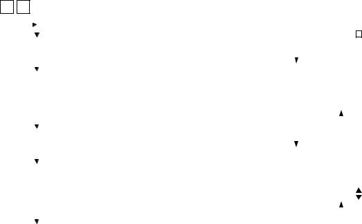
Menu map
The menu below can be selected by pressing the program key. (However, the menu in the broken-dotted box are displayed only when the copier enters the SERVICE MODE.)
01. DEFAULT SETTINGS |
|
|
|
|
|
|
|
|
|
|
|
|
|
02. LISTS |
|
|
|
|
|
|
|
|
|
|
|
|
|
03. INITIAL SETUP |
|
|
|
|
|
|
|
|
|
|
|
|
|
04. MENU LIST |
|
|
|
|
|
|
|
|
|
|
|
|
|
05. TEST MODE |
|
|
|
01. AUTO TEST |
|
|
|||||||
|
|
|
|
|
|||||||||
|
|
|
|
02. INDIVIDUAL TEST |
|
|
|||||||
|
|
|
|
|
|||||||||
|
|
|
|
03. TEST RESULT LIST |
|
|
|||||||
|
|
|
|
|
|||||||||
|
|
|
|
04. FUNCTION TEST |
|
|
|
|
|
01. OPE PANEL TEST |
|||
|
|
|
|
|
|
|
|
||||||
|
|
|
|
05. MAINTENANCE |
|
|
|
|
|
02. PRINT TEST |
|||
|
|
|
|
06. SERVICE LIST |
|
|
|
|
|
01. MEMORY CLEAR |
|||
|
|
|
|
|
|
|
|
|
|
|
|||
|
|
|
|
|
|
|
|
|
|
|
|
|
|
|
|
|
|
|
|
|
|
|
|
|
|
||
|
|
|
|
|
|
|
|
|
|
|
|
|
02. SET FUNCTION |
|
|
|
|
|
|
|
|
|
|
|
|
||
|
|
|
|
|
|
|
|
|
|
|
|
|
01. PROTOCOL TRACE |
|
|
|
|
|
|
|
|
|
|
|
|
|
|
|
|
|
|
|
|
|
|
|
|
|
|
|
|
|
|
|
|
Service mode |
|
|
|
02. TOTAL ERRORS |
|||||
|
|
|
|
|
|
|
|||||||
|
|
|
|
|
|
|
|
||||||
|
|
|
|
|
|
|
|||||||
01-02-02
December 2002 TOSHIBA TEC |
1 - 7 |
e-STUDIO160/200/250 ADJUSTMENT ITEMS |
1.2.1 Adjust mode (05) |
|
<Key used in operation> |
<Display messages> |
|
0 |
|
|
5 |
|
Power ON |
|
|
|
TEST MODE A |
|
|
|
|
|
|
|
|
|
|
|
|
|
|
|
|
|
|
|||||||||||||||||||
|
|
|
|
|
|
|
|
|
|
|
|
|
|
|
|
|
|
|
|
|
|
|
|
|
|
|
|
|
|
|
|
|
|
|
|
|
|
|
|||||||||
|
|
|
|
Enter code |
MC= |
|
|
|
|
|
|
|
|
|
|
|
|
|
|
|
|
|
|
||||||||||||||||||||||||
|
|
|
|
|
|
|
|
|
|
|
|
|
|
|
|
|
|
|
|
|
|
|
|
|
|
|
|
|
|
|
|||||||||||||||||
|
|
|
|
|
|
|
|
|
|
|
|
|
|
|
|
|
|
|
|
|
|
|
|
|
|
|
|
|
|
|
|
|
|
|
|
|
|
|
|
|
|
|
|
|
|||
|
|
|
|
|
|
|
|
|
|
|
|
|
|
|
|
|
|
|
|
|
|
|
|
|
|
|
|
|
|
|
|
|
|
|
|
|
|
|
|
|
|
|
|
|
|||
|
|
|
|
|
|
|
|
|
|
|
|
|
|
|
|
|
|
|
|
|
|
|
|
|
|
|
|
|
|
|
|
|
|
|
|
|
|
|
|
|
|
|
|
|
|||
|
|
Digital Keys |
|
|
|
|
|
|
|
|
|
|
|
|
|
|
|
|
|
|
|
|
|
|
|
|
|
|
|
|
|
|
|
|
|
||||||||||||
|
|
|
|
|
|
|
|
|
|
|
|
|
|
|
|
|
|
|
|
|
|
|
|
|
|
|
|
|
|
|
|
|
|
|
|||||||||||||
|
|
|
|
|
|
|
|
|
|
|
|
|
|
|
|
|
|
|
|
|
|
|
|
|
|
|
|
|
|
|
|
|
|
||||||||||||||
|
|
|
|
|
|
|
|
|
|
|
|
|
( |
C/S |
used to correct value) |
|
|
|
|
|
|
|
|
|
|
|
|
|
|
|
|
|
|
||||||||||||||
|
|
|
|
|
SET |
|
|
|
|
|
|
TEST MODE A |
|
|
|
|
|
|
|
|
|
|
|
|
|
|
|
|
|
|
|||||||||||||||||
|
|
|
|
|
|
|
|
|
|
|
|
|
|
|
|
|
|
|
|
|
|
|
|
|
|
|
|
|
|
|
|
|
|
|
|
|
|
|
|
|
|
|
|
|
|
|
|
|
|
|
|
|
|
|
|
|
|
|
|
|
|
|
|
|
MC= |
|
|
|
|
|
|
|
|
|
|
|
|
|
|
|
|
|
|
||||||||||||
|
|
|
|
|
|
or |
|
|
|
|
|
|
|
|
|
|
|
|
|
|
|
|
|
|
|
|
|
|
|||||||||||||||||||
|
|
|
|
|
|
|
|
|
|
|
|
|
|
|
|
|
|
|
|
|
|
|
|
|
|
|
|
|
|
|
|
|
|
|
|
|
|
|
|
|
|||||||
|
|
|
|
|
|
|
|
|
|
|
|
|
|
|
|
|
|
|
|
|
|
|
|
205 |
|
|
|
|
|
||||||||||||||||||
|
|
|
|
START |
|
|
|
|
|
|
|
|
|
|
|
|
|
|
|
|
|
|
|
|
|
|
|
|
|
||||||||||||||||||
|
|
|
|
|
|
|
|
|
|
|
|
|
|
|
|
|
|
|
|
|
|
|
|
|
|
|
|
|
|
|
|
|
|
|
|
|
|
|
|
|
|
|
|
|
|
|
|
|
|
|
Digital Keys |
|
Adjustment value |
|
|
|
|
|
Enter code |
||||||||||||||||||||||||||||||||||||
|
|
|
|
|
|
|
|
|
|
|
|
|
|
|
|
|
|
|
|
|
|
|
|
|
|
|
|
|
|
|
|
|
|
|
|
|
|
|
|
|
|
|
|
|
|
|
|
|
|
|
|
|
|
|
|
|
|
|
|
|
|
|
|
|
|
|
|
|
|
|
|
|
|
|
|
|
|
|
|||||||||||||||||
|
|
|
|
|
SET |
|
|
|
|
|
|
TEST MODE A |
|
|
|
|
|
|
|
|
|
|
|
|
|
|
|
|
|
|
|||||||||||||||||
|
|
|
|
|
|
|
|
|
|
|
|
|
|
|
|
|
|
|
|
|
|
|
|
|
|
|
|
|
|
|
|
|
|
|
|
|
|
|
|
|
|
|
|
|
|
|
|
|
|
|
|
|
|
|
|
|
|
|
|
|
|
|
|
|
MC=205 |
|
|
|
|
|
|
|
|
|
|
|
|
|
|
|
|
|
|
||||||||||||
|
|
|
|
|
|
or |
|
|
|
|
|
|
|
|
|
|
|
|
|
|
|
|
|
|
|
|
|
|
|||||||||||||||||||
|
|
|
|
|
|
|
|
|
|
|
|
|
|
|
|
|
|
|
|
|
|
|
|
|
|
|
|
|
|
|
|
|
|
|
|
|
|
|
|
|
|||||||
|
|
|
|
|
|
|
|
|
DT= |
156 |
|
|
|
|
|
||||||||||||||||||||||||||||||||
|
|
|
|
START |
|
|
|
|
|
|
|
|
|
|
|
||||||||||||||||||||||||||||||||
|
|
|
|
|
|
|
|
|
|
|
|
|
|
|
|
|
|
|
|
|
|
|
|
|
|
|
|
|
|
|
|
|
|
|
|
|
|||||||||||
|
|
|
|
|
|
|
|
|
|
|
|
|
|
|
|
|
|
|
|
|
|
|
|
|
|
|
|
|
|
|
|
|
|
|
Adjustment value |
||||||||||||
|
|
|
|
Cancel |
|
|
|
|
|
|
|
|
|
|
|
|
|
|
|
|
|
|
|
|
|
|
|
|
|||||||||||||||||||
|
|
|
|
|
|
|
|
|
|
|
|
|
|
|
|
|
|
|
|
|
|
|
|
|
|
|
|
|
|
|
|
|
|
|
|
|
|
|
|
||||||||
|
|
|
|
|
|
|
|
|
|
|
|
|
|
|
|
|
|
|
|
|
|
|
|
|
|
|
|
|
|
|
|
|
|
|
|
|
|
|
|
|
|
|
|
|
|
|
|
e-STUDIO160/200/250 ADJUSTMENT ITEMS |
1 - 8 |
December 2002 TOSHIBA TEC |

ADJUST MODE (05) ITEMS
Process unit adjustment
Code |
Factor |
Adjustment item (05) |
Mode |
Default |
Acceptable |
Refer to |
|
|
|
|
|
value |
page |
|
|
|
|
|
|
|
205 |
Development |
Developer bias DC adjustment |
ALL |
156 |
0-255 |
1-70 |
|
|
• Increment/decrement by U/D (Up/Down) key |
|
(166) |
|
|
|
|
• Real-time high voltage output |
|
|
|
|
|
|
• Developer bias DC ON |
|
|
|
|
|
|
|
|
|
|
|
210 |
Charging |
Grid voltage initial value adjustment |
ALL |
104 |
0-255 |
1-70 |
|
|
• Increment/decrement by U/D key |
|
(118) |
Guaranteed |
|
|
|
• Real-time high voltage output (Charge ON) |
|
|
value |
|
|
|
|
|
*1 |
0-223 |
|
|
|
|
|
|
|
|
220 |
Transfer |
Transfer transformer DC output High adjustment |
ALL |
180 |
0-255 |
1-70 |
|
|
• Increment/decrement by U/D key |
|
|
|
|
|
|
• Real-time high voltage output (Transfer High ON) |
|
|
|
|
|
|
|
|
|
|
|
221 |
Transfer |
Transfer transformer DC output Center adjustment |
ALL |
142 |
0-255 |
1-70 |
|
|
• Increment/decrement by U/D key |
|
(155) |
|
|
|
|
• Real-time high voltage output (Transfer Center ON) |
|
*1 |
|
|
|
|
|
|
|
|
|
233 |
Separation |
Separation output High adjustment |
ALL |
67 |
0-255 |
1-70 |
|
|
• Increment/decrement by U/D key |
|
|
|
|
|
|
• Real-time high voltage output (Separation-High ON) |
|
|
|
|
|
|
|
|
|
|
|
234 |
Separation |
Separation output Center adjustment |
ALL |
49 |
0-255 |
1-70 |
|
|
• Increment/decrement by U/D key |
|
|
|
|
|
|
• Real-time high voltage output (Separation-Center ON) |
|
|
|
|
|
|
|
|
|
|
|
235 |
Separation |
Separation output Low adjustment |
ALL |
35 |
0-255 |
1-70 |
|
|
• Increment/decrement by U/D key |
|
|
|
|
|
|
• Real-time high voltage output (Separation-Low ON) |
|
|
|
|
|
|
|
|
|
|
|
261 |
Laser |
Laser power 600 DPI Initial value adjustment |
ALL |
39 |
0-255 |
|
|
|
• Increment/decrement by U/D key |
|
(53) |
|
|
|
|
• No polygon rotation |
|
*1 |
|
|
|
|
• Real-time laser output |
|
|
|
|
|
|
(Results of automatic laser adjustment) |
|
|
|
|
|
|
(Laser ON) |
|
|
|
|
|
|
|
|
|
|
|
*1 : The value in parentheses is for the model e-STUDIO200/250 series.
December 2002 TOSHIBA TEC |
1 - 9 |
e-STUDIO160/200/250 ADJUSTMENT ITEMS |
Scanning adjustment
Code |
Factor |
Adjustment item (05) |
|
Mode |
Default |
Acceptable |
Refer to |
|
|
|
|
|
|
value |
page |
|
|
|
|
|
|
|
|
304 |
Scanner |
Scanner feed magnification |
0.1 %/step |
ALL |
128 |
0-255 |
1-62 |
|
mechanism |
|
|
|
|
|
|
|
|
|
|
|
|
|
|
305 |
Scanner |
Scanner feed misalignment |
0.126 mm/step |
ALL |
128 |
85-171 |
1-63 |
|
mechanism |
|
(600 DPI) |
|
|
|
|
|
|
|
|
|
|
|
|
306 |
Scanner |
CCD scanning misalignment |
0.04233 mm/step |
ALL |
128 |
5-251 |
1-61 |
|
mechanism |
|
|
|
|
|
|
|
|
|
|
|
|
|
|
354 |
R/ADF |
R/ADF aligning amount (surface) |
0.5 mm/step |
ALL |
10 |
0-20 |
|
|
|
|
|
|
|
|
|
355 |
RADF |
RADF aligning amount (back) |
0.5 mm/step |
ALL |
10 |
0-20 |
|
|
|
|
|
|
|
|
|
356 |
R/ADF |
ADF position sensor adjustment or RADF sensor automatic |
ALL |
- |
*1 |
|
|
|
|
adjustment |
|
|
|
|
|
|
|
|
|
|
|
|
|
357 |
R/ADF |
R/ADF transport speed fine adjustment |
0.1 %/step |
ALL |
50 |
0-100 |
|
|
|
|
|
|
|
|
|
358 |
R/ADF |
R/ADF horizontal misalignment adjustment |
ALL |
128 |
0-255 |
|
|
|
|
|
0.04233 mm/step |
|
|
|
|
|
|
|
|
|
|
|
|
365 |
R/ADF |
RADF top position adjustment (surface) |
0.1 mm/step |
ALL |
50 |
0-100 |
|
|
|
|
|
|
|
|
|
366 |
RADF |
RADF top position adjustment (back) |
0.1 mm/step |
ALL |
50 |
0-100 |
|
|
|
|
|
|
|
|
|
380 |
ADF |
ADF document width sensor adjustment, narrowest document |
ALL |
- |
*1 |
1-52 |
|
|
|
guide width |
|
|
|
|
|
|
|
|
|
|
|
|
|
381 |
ADF |
ADF document width sensor adjustment, widest document |
ALL |
- |
*1 |
1-52 |
|
|
|
guide width |
|
|
|
|
|
|
|
|
|
|
|
|
|
|
|
|
*1 : The entry of code enables automatic adjustment. |
||||
Printer adjustment
Code |
Factor |
|
Adjustment item |
|
Mode |
Default |
Acceptable |
Refer to |
|
|
|
|
|
|
|
|
|
Value |
page |
|
|
|
|
|
|
|
|
||
400 |
Printer system |
Polygon motor speed fine adjustment |
600 DPI |
PPC |
128 |
108-148 |
1-56 |
||
|
|
|
|
|
0.2%/step |
|
|
|
|
|
|
|
|
|
|
|
|
|
|
410 |
Printer system |
Laser start position 600 DPI |
|
Cassette 1 |
PPC |
108 |
0-255 |
1-57 |
|
|
|
|
|
|
|
|
|
|
|
417 |
Printer system |
Laser start position 600 DPI |
|
Cassette 2 |
PPC |
106 |
0-255 |
1-57 |
|
|
|
|
|
|
|
|
|
|
|
418 |
Printer system |
Laser start position 600 DPI |
|
Cassette 3/LCF |
PPC |
119 |
0-255 |
1-57 |
|
|
|
|
|
|
|
|
|
|
|
419 |
Printer system |
Laser start position 600 DPI |
|
Cassette 4 |
PPC |
128 |
0-255 |
1-57 |
|
|
|
|
|
|
|
|
|
||
421 |
Printer system |
Main motor speed fine adjustment |
Approx. 0.1%/step |
PPC |
124 (130) |
78-178 |
1-58 |
||
|
|
|
|
|
|
|
|
|
|
430 |
Printer system |
Top margin |
0.7 mm/step |
|
PPC |
0 |
0-30 |
1-64 |
|
|
|
|
|
|
|
|
|
|
|
431 |
Printer system |
Left margin |
0.1 mm/step |
|
PPC |
0 |
0-255 |
1-64 |
|
|
|
|
|
|
|
|
|
|
|
432 |
Printer system |
Right margin |
0.1 mm/step |
|
PPC |
0 |
0-255 |
1-65 |
|
|
|
|
|
|
|
|
|
|
|
433 |
Printer system |
Bottom margin |
0.1 mm/step |
|
PPC |
0 |
0-255 |
1-65 |
|
|
|
|
|
|
|
|
|
||
440 |
Printer system |
Top position Cassette 1 |
0.4 mm/step |
ALL |
23 |
0-40 |
1-59 |
||
|
|
|
|
|
|
|
|
||
441 |
Printer system |
Top position Cassette 2 |
0.4 mm/step |
ALL |
7 |
0-15 |
1-59 |
||
|
|
|
|
|
|
|
|
||
442 |
Printer system |
Top position Bypass (SFB) |
0.4 mm/step |
ALL |
8 |
0-15 |
1-59 |
||
|
|
|
|
|
|
|
|
|
|
443 |
Printer system |
Top position LCF |
|
0.4 mm/step |
ALL |
8 |
0-15 |
1-59 |
|
|
|
|
|
|
|
|
|
|
|
444 |
Printer system |
Top position PFP |
|
0.4 mm/step |
ALL |
7 |
0-15 |
1-59 |
|
|
|
|
|
|
|
|
|
|
|
445 |
Printer system |
Top position ADU |
|
0.4 mm/step |
ALL |
8 |
0-15 |
1-59 |
|
|
|
|
|
|
|
|
|||
450 |
Printer system |
Aligning amount Copier cassette (Cassette 1) |
ALL |
14 |
0-31 |
1-55 |
|||
|
|
Long size (0.52 mm/step) Paper length of min. 259 mm |
|
|
|
|
|||
|
|
|
|
|
|
|
|||
451 |
Printer system |
Aligning amount Copier cassette (Cassette 1) |
ALL |
14 |
0-31 |
1-55 |
|||
|
|
Short size (0.52 mm/step) Paper length of max. 258 mm |
|
|
|
|
|||
|
|
|
|
|
|
|
|
||
452 |
Printer system |
Aligning amount Cassette 2 (PFU) |
|
ALL |
22 |
0-31 |
1-55 |
||
|
|
Long size (0.52 mm/step) Paper length of min. 322 mm |
|
|
|
|
|||
|
|
|
|
|
|
|
|
|
|
|
|
|
|
*1 : The value in parentheses is for the model e-STUDIO200/250 series. |
|||||
e-STUDIO160/200/250 ADJUSTMENT ITEMS |
1 - 10 |
December 2002 TOSHIBA TEC |

Printer adjustment
Code |
Factor |
Adjustment item |
Mode |
Default |
Acceptable |
Refer to |
|
|
|
|
|
|
|
Value |
page |
|
|
|
|
|
|
|
|
453 |
Printer system |
Aligning amount Cassette 2 (PFU) |
ALL |
16 |
0-31 |
1-55 |
|
|
|
Short size (0.52 mm/step) Paper length of max. 321 mm |
|
|
|
|
|
|
|
|
|
|
|
|
|
455 |
Printer system |
Aligning amount ADU |
|
ALL |
26 |
0-31 |
1-55 |
|
|
(e-STUDIO160:0.7mm/step, e-STUDIO200/250:0.47mm/step) |
|
(23) *1 |
|
|
|
|
|
|
|
|
|
|
|
456 |
Printer system |
Aligning amount PFP Short size (0.52 mm/step) |
ALL |
16 |
0-31 |
1-55 |
|
|
|
Paper length of max. 321 mm |
|
|
|
|
|
|
|
|
|
|
|
|
|
457 |
Printer system |
Aligning amount LCF |
0.52 mm/step |
ALL |
16 |
0-31 |
1-55 |
|
|
|
|
|
|
|
|
458 |
Printer system |
Aligning amount Bypass (SFB) Short size (0.52 mm/step ) |
ALL |
21 |
0-31 |
1-55 |
|
|
|
Paper length of max. 258 mm |
|
|
|
|
|
|
|
|
|
|
|
|
|
463 |
Printer system |
Aligning amount PFP Long size (0.52 mm/step) |
ALL |
18 |
0-31 |
1-55 |
|
|
|
Paper length of min. 322 mm |
|
|
|
|
|
|
|
|
|
|
|
|
|
465 |
Printer system |
Aligning amount Bypass Long size (0.52 m/step) |
ALL |
28 |
0-31 |
1-55 |
|
|
|
Paper length of min. 259 mm |
|
|
|
|
|
|
|
|
|
|
|
|
|
497 |
Printer system |
Laser start position 600 DPI Bypass |
PPC |
101 |
0-255 |
1-57 |
|
|
|
|
|
|
|
|
|
*1 : The value in parentheses is for the model e-STUDIO200/250 series.
Scan image processing parameter 600 DPI
|
|
|
Image |
Image |
|
Acceptable |
Refer to |
|
Code |
Factor |
Adjustment item |
quality |
Default |
||||
mode |
value *1 |
page |
||||||
|
|
|
mode |
|
||||
|
|
|
|
|
|
|
||
|
|
|
|
|
|
|
|
|
501 |
Density |
Manual density fine adjustment Center |
PPC |
Photo |
139 |
0-255 |
1-53 |
|
|
|
value |
|
|
|
L ← V → D |
|
|
|
|
|
|
|
|
|
|
|
503 |
Density |
Ditto |
PPC |
Text/Photo |
133 |
0-255 |
1-53 |
|
|
|
|
|
|
|
L ← V → D |
|
|
|
|
|
|
|
|
|
|
|
504 |
Density |
Ditto |
PPC |
Text |
130 |
0-255 |
1-53 |
|
|
|
|
|
|
|
L ← V → D |
|
|
|
|
|
|
|
|
|
|
|
505 |
Density |
Manual density fine adjustment Light step |
PPC |
Text/Photo |
28 |
0-255 |
1-53 |
|
|
|
value |
|
|
|
V → L |
|
|
|
|
|
|
|
|
|
|
|
506 |
Density |
Ditto |
PPC |
Photo |
18 |
0-255 |
1-53 |
|
|
|
|
|
|
|
V → L |
|
|
|
|
|
|
|
|
|
|
|
507 |
Density |
Ditto |
PPC |
Text |
20 |
0-255 |
1-53 |
|
|
|
|
|
|
|
V → L |
|
|
|
|
|
|
|
|
|
|
|
508 |
Density |
Manual density fine adjustment Dark step |
PPC |
Text/Photo |
13 |
0-255 |
1-53 |
|
|
|
value |
|
|
|
V → D |
|
|
|
|
|
|
|
|
|
|
|
509 |
Density |
Ditto |
PPC |
Photo |
20 |
0-255 |
1-53 |
|
|
|
|
|
|
|
V → D |
|
|
|
|
|
|
|
|
|
|
|
510 |
Density |
Ditto |
PPC |
Text |
18 |
0-255 |
1-53 |
|
|
|
|
|
|
|
V → D |
|
|
|
|
|
|
|
|
|
|
|
512 |
Density |
Auto density fine adjustment |
PPC |
Photo |
140 |
0-255 |
1-53 |
|
|
|
|
|
|
|
L ← V → D |
|
|
|
|
|
|
|
|
|
|
|
514 |
Density |
Ditto |
PPC |
Text/Photo |
133 |
0-255 |
1-53 |
|
|
|
|
|
|
|
L ← V → D |
|
|
|
|
|
|
|
|
|
|
|
515 |
Density |
Ditto |
PPC |
Text |
130 |
0-255 |
1-53 |
|
|
|
|
|
|
|
L ← V → D |
|
|
|
|
|
|
|
|
|
|
|
593 |
Density |
ϒ data inclination correction |
PPC |
Text/Photo |
0 |
0-9 |
1-67 |
|
|
|
|
|
|
|
|
|
|
594 |
Density |
ϒ data inclination correction |
PPC |
Photo |
0 |
0-9 |
1-67 |
|
|
|
|
|
|
|
|
|
|
595 |
Density |
ϒ data inclination correction |
PPC |
Text |
0 |
0-9 |
1-67 |
|
|
|
|
|
|
|
|
|
*1 L: Light, V: Value, D: Dark
December 2002 TOSHIBA TEC |
1 - 11 |
e-STUDIO160/200/250 ADJUSTMENT ITEMS |
Scan image processing parameter 600 DPI
|
|
|
|
Image |
Image |
|
Acceptable |
Refer to |
|
Code |
Factor |
Adjustment item |
quality |
Default |
|||||
mode |
value *1 |
page |
|||||||
|
|
|
|
mode |
|
||||
|
|
|
|
|
|
|
|
||
|
|
|
|
|
|
|
|
||
620 |
Image |
No. of units: HPF table number |
PPC |
Text/Photo |
1 |
0-99 |
1-66 |
||
|
quality |
0: Use of default value |
|
|
|
The larger the intensity |
|
||
|
|
1: Text/Photo mode |
|
|
|
|
coefficient the stronger the |
|
|
|
|
2: Photo mode |
|
|
|
|
intensity. |
|
|
|
|
3: For Text mode |
|
|
|
|
|
|
|
|
|
4 - 9: Unused |
|
|
|
|
|
|
|
|
|
No. of tens: Filter combination intensity |
|
|
|
|
|
||
|
|
0: Use of default value |
|
|
|
|
|
||
|
|
1 - 9: Filter combination intensity |
|
|
|
|
|
||
|
|
|
|
|
|
|
|
|
|
621 |
Image |
Ditto |
|
PPC |
Photo |
2 |
0-99 |
1-66 |
|
|
quality |
|
|
|
|
|
|
|
|
|
|
|
|
|
|
|
|
|
|
622 |
Image |
Ditto |
|
PPC |
Text |
3 |
0-99 |
1-66 |
|
|
quality |
|
|
|
|
|
|
|
|
|
|
|
|
|
|
|
|
||
693 |
Density |
Range correction on original set on the |
PPC |
Text/Photo |
12 |
11-14 |
|
||
|
|
ADF or RADF. |
|
|
|
|
21-24 |
|
|
|
|
Set whether the value of the background |
|
|
|
31-34 |
|
||
|
|
peak and text peak are fixed or not. |
|
|
|
41-44 |
|
||
|
|
If they are fixed, the range correction is |
|
|
|
|
|
||
|
|
performed with standard values. |
|
|
|
|
|
||
|
|
The values of the background peak and |
|
|
|
|
|
||
|
|
text peak affect the reproduction of the |
|
|
|
|
|
||
|
|
background density and text density re- |
|
|
|
|
|
||
|
|
spectively. |
|
|
|
|
|
|
|
|
|
The number of units: Data while automatic |
|
|
|
|
|
||
|
|
density is selected. |
|
|
|
|
|
|
|
|
|
The number of tens: Data while manual |
|
|
|
|
|
||
|
|
density is selected. |
|
|
|
|
|
|
|
|
|
Background peak |
Text peak |
|
|
|
|
|
|
|
|
1: fixed |
fixed |
|
|
|
|
|
|
|
|
2: varied |
fixed |
|
|
|
|
|
|
|
|
|
|
|
|
|
|
|
|
694 |
|
3: fixed |
varied |
|
Photo |
12 |
|
|
|
|
|
|
|
|
|
|
|
|
|
695 |
|
4: varied |
varied |
|
Text |
44 |
|
|
|
|
|
|
|
|
|
|
|
|
|
e-STUDIO160/200/250 ADJUSTMENT ITEMS |
1 - 12 |
December 2002 TOSHIBA TEC |
1.2.2 System mode
<Key used in operation>
|
0 |
|
|
8 |
|
Power ON |
|
|
|
|||
|
|
|
|
|
|
|
|
|
|
Enter code |
||
|
|
|
|
|
|
|
|
|
||||
|
|
|
Digital Keys |
|
||||||||
|
|
|
|
|
|
|
|
|
|
|
|
|
|
|
|
|
|
|
|
|
|
|
( |
C/S |
used to correct value) |
|
|
|
|
|
|
|
|
|
|
|
|
|
SET
or
START
|
|
|
|
Setting value |
Digital Keys |
||||
|
|
|
|
|
SET
or
START
Cancel
SYSTEM MODE (08) ITEMS
<Display messages>
TEST MODE D
MC=
TEST MODE D
MC=
204
Enter code
TEST MODE D
MC=204
DT= |
1 |
Setting value
|
|
|
|
|
|
|
|
|
|
|
Image |
|
Acceptable |
Refer to |
Code |
Factor |
|
|
Setting item |
|
|
Mode |
quality |
Default |
|||||
|
|
|
|
value *1 |
page |
|||||||||
|
|
|
|
|
|
|
|
|
|
|
mode |
|
||
|
|
|
|
|
|
|
|
|
|
|
|
|
|
|
|
|
|
|
|
|
|
|
|
||||||
202 |
SYS |
Selection of external counter |
|
ALL |
|
0 |
0-3 |
|
||||||
|
|
0: No external counter |
|
|
|
|
|
|
|
|||||
|
|
1: With coil controller |
|
|
|
|
|
|
|
|||||
|
|
2: Non-standard: With copylizer/key |
|
|
|
|
|
|||||||
|
|
card |
|
|
|
|
|
|
|
|
|
|
|
|
|
|
3: With key counter |
|
|
|
|
|
|
|
|||||
|
|
|
|
|
|
|
|
|
|
|
|
|
||
204 |
SYS |
Auto clear [sec] |
|
|
|
|
|
ALL |
|
3 |
0-15 |
|
||
|
|
0: Invalid 1: 15s 2: 30s 3: 45s 4: 60s |
|
|
|
|
|
|||||||
|
|
5: 75s |
6: 90s |
7: 105s |
8: 120s |
|
|
|
|
|
||||
|
|
9: 135s |
|
10: 150s |
11: 180s |
12: 210s |
|
|
|
|
|
|||
|
|
13: 240s |
14: 270s |
15: 300s |
|
|
|
|
|
|||||
|
|
|
|
|
|
|
|
|
||||||
205 |
SYS |
Auto low power 0: Invalid |
1: Valid |
ALL |
|
1 |
0-1 |
|
||||||
|
|
(Time is set on panel.) |
|
|
|
|
|
|
|
|
||||
|
|
|
|
|
|
|
|
|
|
|
|
|||
206 |
SYS |
Auto sleep |
|
0: Invalid |
1: Valid |
|
ALL |
|
1 |
0-1 |
|
|||
|
|
(Time is set on panel.) |
|
|
|
|
|
|
|
|
||||
|
|
|
|
|
|
|
|
|
||||||
207 |
SYS |
Display for key counter setting |
|
ALL |
|
0 |
0-1 |
|
||||||
|
|
0: Set key copy counter |
|
|
|
|
|
|
||||||
|
|
1: ASK CASHIER TO SWITCH ON |
|
|
|
|
|
|||||||
|
|
* Valid when 08-202 is set to 3 (With key |
|
|
|
|
|
|||||||
|
|
counter). |
|
|
|
|
|
|
|
|
|
|
|
|
|
|
|
|
|
|
|
|
|
|
|
|
|
|
|
|
|
|
|
|
|
|
|
|
|
|
*1 : The entry of code enables automatic execution. |
|||
December 2002 TOSHIBA TEC |
1 - 13 |
e-STUDIO160/200/250 ADJUSTMENT ITEMS |
SYSTEM MODE (08) ITEMS
|
|
|
|
|
Image |
|
Acceptable |
Refer to |
Code |
Factor |
|
Setting item |
Mode |
quality |
Default |
||
|
value *1 |
page |
||||||
|
|
|
|
|
mode |
|
||
|
|
|
|
|
|
|
|
|
|
|
|
|
|
|
|
|
|
224 |
SYS |
SFB paper size |
|
|
14 |
0-14 |
|
|
|
|
0: A3 (8K) 1: A4 (16K) 2: A4R (16KR) |
|
|
|
|
|
|
|
|
3: A5R 4: B4 5: B5 6: B5R |
|
|
|
|
|
|
|
|
7: LETTER 8: LETTER-R |
|
|
|
|
|
|
|
|
9: LEDGER 10: LEGAL |
|
|
|
|
|
|
|
|
11: STATEMENT-R 12: COMPUTER |
|
|
|
|
|
|
|
|
13: FOLIO 14: Undefined |
|
|
|
|
|
|
|
|
15-17: Reserved |
|
|
|
|
|
|
|
|
|
|
|
|
|
|
|
225 |
SYS |
Copier cassette paper size |
|
|
NAD: 7 |
0-13 |
|
|
|
|
0: A3 (8K) 1: A4 (16K) 2: A4R (16KR) |
|
|
Other: 1 |
|
|
|
|
|
3: A5R 4: B4 5: B5 6: B5R |
|
|
|
|
|
|
|
|
7: LETTER 8: LETTER-R 9: LEDGER |
|
|
|
|
|
|
|
|
10: LEGAL 11: STATEMENT-R |
|
|
|
|
|
|
|
|
12: COMPUTER 13: FOLIO |
|
|
|
|
|
|
|
|
14: Reserved 15: Reserved |
|
|
|
|
|
|
|
|
|
|
|
|
|
|
|
226 |
SYS |
Cassette 2 paper size (Same as 08-225) |
|
|
NAD: 7 |
0-13 |
|
|
|
|
|
|
|
|
Other: 1 |
|
|
|
|
|
|
|
|
|
|
|
227 |
SYS |
Cassette 3 paper size (Same as 08-225) |
|
|
NAD: 7 |
0-13 |
|
|
|
|
(e-STUDIO200/250 series) |
|
|
Other: 1 |
|
|
|
|
|
|
|
|
|
|
|
|
228 |
SYS |
Cassette 4 paper size (Same as 08-225) |
|
|
NAD: 7 |
0-13 |
|
|
|
|
(e-STUDIO200/250 series) |
|
|
Other: 1 |
|
|
|
|
|
|
|
|
|
|
|
|
246 |
SYS |
Clearing copy jobs at auto clear |
ALL |
|
0 |
0-1 |
|
|
|
|
0: No clearing 1: Clearing |
|
|
|
|
|
|
|
|
|
|
|
|
|
|
|
250 |
MAINT |
Service personnel telephone number |
ALL |
|
|
20 digits |
|
|
|
|
|
|
|
|
|
Own M/C registration area |
|
|
|
|
|
|
|
|
|
|
251 |
MAINT |
PM counter setting value |
ALL |
|
NAD: |
0-999999 |
|
|
|
|
|
|
|
|
e-STUDIO160/ |
|
|
|
|
|
|
|
|
200: 81000 |
|
|
|
|
|
|
|
|
e-STUDIO250: |
|
|
|
|
|
|
|
|
99000 |
|
|
|
|
|
|
|
|
Othre: 0 |
|
|
|
|
|
|
|
|
|
|
|
252 |
MAINT |
PM counter present value |
ALL |
|
0 |
0-999999 |
|
|
|
|
08-251: Operates when other than 0 |
|
|
|
|
|
|
|
|
Object of 08-352 |
|
|
|
|
|
|
|
|
|
|
|
|
|
|
|
255 |
MAINT |
PFP installation status |
ALL |
|
0 |
0-4 |
|
|
|
|
0: Auto (Automatically changed to 1 |
|
|
|
|
|
|
|
|
|
or 2 by observing the PFC cassette |
|
|
|
|
|
|
|
|
installation status.) |
|
|
|
|
|
|
|
1: PFP (Cassette 3) |
|
|
|
|
|
|
|
|
2: PFP (Cassette 3,4) |
|
|
|
|
|
|
|
|
|
(e-STUDIO200/250 series) |
|
|
|
|
|
|
|
3: Reserved 4: None |
|
|
|
|
|
|
|
|
|
|
|
|
|
|
|
256 |
MAINT |
LCF paper size |
ALL |
|
NAD: 1 |
0-2 |
|
|
|
|
0: A4 1: LT 2: Reserved |
|
|
Other: 0 |
|
|
|
|
|
|
|
|
|
|
|
|
300 |
OPE. |
MAX . 9 |
ALL |
|
0 |
0-2 |
|
|
|
|
0: |
999 |
|
|
|
|
|
|
|
1: |
99 |
|
|
|
|
|
|
|
2: |
9 |
|
|
|
|
|
|
|
|
|
|
|
|
|
|
340 |
MAINT |
Drum end counter setting value. |
ALL |
|
e-STUDIO160/ |
0-99999 |
|
|
|
|
|
|
|
|
200: 27000 |
(0: Not displayed) |
|
|
|
|
|
|
|
e-STUDIO250: |
|
|
|
|
|
|
|
|
33000 |
|
|
|
|
|
|
|
|
|
|
|
351 |
COUNT |
Display of total counter data |
ALL |
|
|
Display only |
|
|
|
|
(Confirmed by listing and changed by |
|
|
|
|
|
|
|
|
memory writing) |
|
|
|
|
|
|
|
|
|
|
|
|
|
|
|
352 |
COUNT |
A3/LD double count |
ALL |
|
1 |
0-1 |
|
|
|
|
0: Single count 1: Double count |
|
|
|
|
|
|
|
|
|
|
|
|
|
|
|
355 |
COUNT |
Display of drum lite counter |
ALL |
|
0 |
Display only |
|
|
|
|
|
|
|
|
|
|
|
374 |
COUNT |
ADF/RADF scan counter |
ALL |
|
|
0-999999 |
|
|
|
|
|
|
|
*1 : The entry of code enables automatic execution. |
|||
e-STUDIO160/200/250 ADJUSTMENT ITEMS |
1 - 14 |
December 2002 TOSHIBA TEC |
|
|
|
|
|
Image |
|
Acceptable |
Refer to |
|
|
Code |
Factor |
|
Setting item |
Mode |
quality |
Default |
|
|
||
|
value *1 |
page |
|
|
||||||
|
|
|
|
|
mode |
|
|
|
||
|
|
|
|
|
|
|
|
|
|
|
|
|
|
|
|
|
|
|
|
|
|
375 |
COUNT |
COPY job (print) counter |
ALL |
|
|
Double counted if printing |
|
|
|
|
|
|
|
|
|
|
|
A3 or LD size paper |
|
|
|
|
|
|
|
|
|
|
|
|
|
|
376 |
COUNT |
PRINTER job (print) counter |
ALL |
|
|
Double counted if printing |
|
|
|
|
|
|
|
|
|
|
|
A3 or LD size paper |
|
|
|
|
|
|
|
|
|
|
|
|
|
|
377 |
COUNT |
FAX job (print) counter |
ALL |
|
|
Double counted if printing |
|
|
|
|
|
|
|
|
|
|
|
A3 or LD size paper |
|
|
|
|
|
|
|
|
|
|
|
|
|
|
|
|
|
|
|
|
|
|
|
|
|
385 |
COUNT |
Total counter in scanner unit (display) |
ALL |
|
|
0-999999 |
|
|
|
|
|
|
|
|
|
|
|
|
|
|
|
386 |
COUNT |
Platen scan count |
ALL |
|
|
0-999999 |
|
|
|
|
|
|
|
|
|
|
|
|
|
|
|
388 |
COUNT |
LOAD instruction for total counter when |
ALL |
|
|
|
1-90 |
|
|
|
|
|
replacing the main PWA Scanner unit → |
|
|
|
|
|
|
|
|
|
|
Copier |
|
|
|
*1 |
|
|
|
|
|
|
|
|
|
|
|
|
|
|
|
389 |
COUNT |
SAVE instruction for total counter when |
ALL |
|
|
|
|
|
|
|
|
|
replacing the scanner unit Copier → Scan- |
|
|
|
|
|
|
|
|
|
|
ner unit |
|
|
|
*1 |
|
|
|
|
|
|
|
|
|
|
|
|
|
|
|
400 |
Process |
Thermistor heater status counter |
ALL |
|
0 |
0-10 |
|
|
|
|
|
|
0: No error occurrence |
|
|
|
|
|
|
|
|
|
|
1: |
C41 1st thermistor or heater error |
|
|
|
|
|
|
|
|
|
|
when starting W-UP |
|
|
|
|
|
|
|
|
|
2: |
C41 2nd thermistor or heater error |
|
|
|
|
|
|
|
|
|
|
when starting W-UP |
|
|
|
|
|
|
|
|
|
3: Reserved |
|
|
|
|
|
|
|
|
|
|
4: |
C43 Thermistor error during W-UP |
|
|
|
|
|
|
|
|
|
5: |
C44 Heater error during W-UP |
|
|
|
|
|
|
|
|
|
6: |
C43 Thermistor error after ready |
|
|
|
|
|
|
|
|
|
7: |
C44 Heater error after ready |
|
|
|
|
|
|
|
|
|
8: |
C45 Heater end thermistor error af- |
|
|
|
|
|
|
|
|
|
|
ter ready (High temperature) |
|
|
|
|
|
|
|
|
|
9: |
C44 High temperature heater error |
|
|
|
|
|
|
|
|
|
10: |
C45 Heater end thermistor error af- |
|
|
|
|
|
|
|
|
|
|
ter ready (Low temperature) |
|
|
|
|
|
|
|
|
|
|
|
|
|
|
|
|
|
|
401 |
Process |
Drum life counter |
|
|
0 |
0-999999 |
|
|
|
|
|
|
|
|
|
|
|
|
|
|
|
402 |
Process |
Power on hours counter |
|
|
0 |
0-9999959 |
|
|
|
|
|
|
(7-digit display: Hour 5-digit, minute 2- |
|
|
|
Counter area added |
|
|
|
|
|
|
digit) |
|
|
|
|
|
|
|
|
|
|
Total power ON hours |
|
|
|
|
|
|
|
|
|
|
|
|
|
|
|
|
|
|
|
403 |
Process |
Fuser counter |
|
|
0 |
0-999999 |
|
|
|
|
|
|
Always double count for A3, B4, LD, LG, |
|
|
|
Counter area added |
|
|
|
|
|
|
COM, A4R, LTR, and FOLIO |
|
|
|
|
|
|
|
|
|
|
|
|
|
|
|
|
|
|
|
404 |
Process |
Developer material counter. |
|
|
0 |
0-999999 |
|
|
|
|
|
|
Always double count for A3, B4, LD, LG, |
|
|
|
Counter area added |
|
|
|
|
|
|
COM, A4R, LTR, and FOLIO. |
|
|
|
|
|
|
|
|
|
|
Clear by installing a new PU. |
|
|
|
|
|
|
|
|
406 |
Process |
|
|
|
|
|
|
|
|
|
Pre-run start time |
ALL |
|
0 |
0-7 |
|
|
|
|||
|
|
0: Invalid 1: 30 sec 2: 35 sec |
|
|
|
|
|
|
|
|
|
|
3: 40 sec 4: 45 sec 5: 50 sec |
|
|
|
|
|
|
|
|
|
|
6: 55 sec 7: 60 sec |
|
|
|
|
|
|
|
|
407 |
Process |
|
|
|
|
|
|
|
|
|
Pre-run operation time |
ALL |
|
0 |
0-10 |
|
|
|
|||
|
|
0: Invalid 1: 5 sec 2: 10 sec |
|
|
(2) |
|
|
|
|
|
|
|
3: 15 sec 4: 20 sec 5: 25 sec |
|
|
|
|
|
|
|
|
|
|
6: 30 sec 7: 40 sec 8: 50 sec |
|
|
|
|
|
|
|
|
|
|
9: 60 sec 10: 150 sec |
|
|
*1 |
|
|
|
|
|
408 |
Process |
|
|
|
|
|
|
|
|
|
Pre-run operation time for thick paper |
ALL |
|
10 |
0-15 |
|
|
|
|||
|
|
0: Invalid 1: 1 sec 2: 2 sec 3: 3 sec |
|
|
|
|
|
|
|
|
|
|
4: 4 sec 5: 5 sec 6: 6 sec 7: 7 sec |
|
|
|
|
|
|
|
|
|
|
8: 8 sec 9: 9 sec 10: 10 sec |
|
|
|
|
|
|
|
|
|
|
11: 12 sec 12: 14 sec 13: 16 sec |
|
|
|
|
|
|
|
|
|
|
14: 18 sec 15: 20 sec |
|
|
|
|
|
|
|
|
|
|
|
|
|
|
|
|
|
|
|
|
|
|
|
|
*1 : The entry of code enables automatic execution. |
|
||||
December 2002 TOSHIBA TEC |
1 - 15 |
e-STUDIO160/200/250 ADJUSTMENT ITEMS |
|
|
|
|
|
|
|
Image |
|
Acceptable |
Refer to |
Code |
Factor |
|
Setting item |
Mode |
quality |
Default |
||||
|
value *1 |
page |
||||||||
|
|
|
|
|
|
|
mode |
|
||
|
|
|
|
|
|
|
|
|
|
|
|
|
|
|
|
|
|
|
|||
410 |
Process |
Fixing temperature when printing |
ALL |
|
8 |
4-13 |
|
|||
|
|
4: 170°C 5: 175°C 6: 180°C 7: 185°C |
|
|
(10) |
|
|
|||
|
|
8: 190°C |
9: 195°C |
10: 200°C |
|
|
|
|
|
|
|
|
11: 205°C |
12: 210°C |
13: 215°C |
|
|
*1 |
|
|
|
|
|
|
|
|
|
|
|
|||
411 |
Process |
Fixing temperature when ready |
ALL |
|
7 |
0-7 |
|
|||
|
|
0: 170°C 1: 175°C 2: 180°C 3: 185°C |
|
|
|
|
|
|||
|
|
4: 190°C |
5: 195°C |
6: 200°C |
|
|
|
|
|
|
|
|
7: Drop control ON |
|
|
|
|
|
|
|
|
|
|
|
|
|
|
|
|
|||
412 |
Process |
Fixing temperature in low power state |
ALL |
|
NAD: 5 |
0-5 |
|
|||
|
|
0: OFF 1: 120°C 2: 130°C 3: 140°C |
|
|
Other: 4 |
|
|
|||
|
|
4: 150°C 5: 160°C |
|
|
|
|
(NAD: 3) |
|
|
|
|
|
|
|
|
|
|
|
(Other: 2) *1 |
|
|
|
|
|
|
|
|
|
|
|||
413 |
Process |
Fixing temperature for thick paper |
ALL |
|
0 |
0-4 |
|
|||
|
|
0: Invalid 1: 195°C 2: 200°C 3: 205°C |
|
|
(2) |
|
|
|||
|
|
4: 210°C |
|
|
|
|
|
*1 |
|
|
|
|
|
|
|
|
|
|
|||
446 |
Process |
Correction for transfer output ON timing. |
ALL |
|
11 |
0-18 |
1-91 |
|||
*2 |
|
(0: -110 ms -----18: +70 ms) |
|
|
|
10 ms/step |
|
|||
|
|
|
|
|
|
|
|
|||
447 |
Process |
Correction for transfer output OFF timing. |
ALL |
|
1 |
0-18 |
1-91 |
|||
*2 |
|
(0: +110 ms -----18: -70 ms) |
|
|
(11) *1 |
10 ms/step |
|
|||
|
|
|
|
|
|
|
|
|||
462 |
|
Setting for switchback operation to copy |
|
|
0 |
0-1 |
|
|||
|
|
mixed-size originals form RADF |
|
|
|
|
|
|||
|
|
0: Invalid 1: Valid |
|
|
|
|
|
|
|
|
|
|
|
|
|
|
|
|
|||
480 |
Cassette priority selection |
ALL |
|
0 |
0-5 |
|
||||
|
|
0: A4/LT 1: LCF 2: Cassette 1 |
|
|
|
|
|
|||
|
|
3: Cassette 2 4: Cassette 3 |
|
|
|
|
|
|||
|
|
5: Cassette 4 |
|
|
|
|
|
|
|
|
|
|
|
|
|
|
|
|
|
|
|
481 |
Auto cassette change |
|
|
ALL |
|
1 |
0-1 |
|
||
|
|
0: None 1: Normal |
|
|
|
|
|
|
|
|
|
|
|
|
|
|
|
|
|||
483 |
Polygon motor preceding start-up setting |
ALL |
|
0 |
0-2 |
|
||||
|
|
0: Valid (DF, platen) |
1: Invalid |
|
|
|
|
|
||
|
|
2: DF only |
|
|
|
|
|
|
|
|
|
|
|
|
|
|
|
|
|||
486 |
Time for suspension of the Polygonal mo- |
ALL |
|
0 |
0-2 |
|
||||
|
|
tor pre-running |
|
|
|
|
|
|
|
|
|
|
(0: 15 sec, 1: 30 sec, 2: 45 sec) |
|
|
|
|
|
|||
|
|
|
|
|
|
|
|
|||
503 |
Image |
Density default in image quality mode |
PPC |
ALL |
0 |
0-8 |
|
|||
|
processing |
0: AUTO 1: Light 3 2: Light 2 |
|
|
|
|
|
|||
|
|
3: Light 1 |
4: Center |
5: Dark 1 |
|
|
|
|
|
|
|
|
6: Dark 2 7: Dark 3 |
|
|
|
|
|
|
|
|
|
|
Also reflected on panel. |
|
|
|
|
|
|
||
504 |
F/W |
Special paper selection |
|
PPC |
|
0 |
0-2 |
|
||
|
|
0: FOLIO/B size |
|
|
|
|
|
|
|
|
|
|
1: 13" LEGAL (South America only) |
|
|
|
|
|
|||
|
|
2: K size (China only) |
|
|
|
|
|
|
||
|
|
|
|
|
|
|
|
|
|
|
550 |
Image |
Image mode default |
|
|
PPC |
ALL |
0 |
0-2 |
|
|
|
processing |
0: Standard 1: Photo |
2: Text |
|
|
|
|
|
||
603 |
F/W |
Auto duplex mode (when document is |
PPC |
|
0 |
0-2 |
|
|||
|
|
loaded into DF) |
|
|
|
|
|
|
|
|
|
|
0: Invalid |
1: Simplex/Duplex |
|
|
|
|
|
||
|
|
2: Duplex/Duplex |
|
|
|
|
|
|
|
|
|
|
|
|
|
|
|
|
|
|
|
604 |
F/W |
APS priority selection |
|
|
PPC |
|
0 |
0-3 |
|
|
|
|
0: APS 1: AMS 2: None (100%) |
|
|
|
|
|
|||
|
|
3: Reserved |
|
|
|
|
|
|
|
|
|
|
|
|
|
|
|
|
|||
611 |
F/W |
Book duplex document selection |
PPC |
|
0 |
0-1 |
|
|||
|
|
0: Left-hand open 1: Right-hand open |
|
|
|
|
|
|||
614 |
F/W |
The function clear LED blinks. Blinks when |
PPC |
|
1 |
0-1 |
|
|||
|
|
the value is different from the present de- |
|
|
|
|
|
|||
|
|
fault value after copying (until auto clear |
|
|
|
|
|
|||
|
|
or all clear.) |
|
|
|
|
|
|
|
|
|
|
0: Invalid (Always off) |
1: Valid |
|
|
|
|
|
||
|
|
|
|
|
|
|
|
|
|
|
*1 : The value in parentheses is for the model e-STUDIO200/250 series.
*2 : This value should be adjusted at the factory. Do not change the value in the field. When the main PWA is replaced, it should be entered again.
e-STUDIO160/200/250 ADJUSTMENT ITEMS |
1 - 16 |
December 2002 TOSHIBA TEC |
|
|
|
|
Image |
|
Acceptable |
|
Refer to |
|
|
Code |
Factor |
Setting item |
Mode |
quality |
Default |
|
|
|
||
value *1 |
|
page |
|
|
||||||
|
|
|
|
mode |
|
|
|
|
||
|
|
|
|
|
|
|
|
|
|
|
|
|
|
|
|
|
|
|
|
|
|
618 |
F/W |
Default setting for mixed size originals |
PPC |
|
0 |
0-1 |
|
|
|
|
|
|
0: OFF |
|
|
|
|
|
|
|
|
|
|
1: ON |
|
|
|
|
|
|
|
|
|
|
* Setting 08-618 to 1 (ON) and 08-641 to |
|
|
|
|
|
|
|
|
|
|
4 (alternate) simultaneously is not al- |
|
|
|
|
|
|
|
|
|
|
lowed. |
|
|
|
|
|
|
|
|
|
|
|
|
|
|
|
|
|
|
|
620 |
F/W |
APS forced start (Exclude RADF) |
Memory |
|
0 |
0-2 |
|
|
|
|
|
|
0: Valid (One time pressing) |
PPC |
|
|
|
|
|
|
|
|
|
1: Reserved |
|
|
|
|
|
|
|
|
|
|
2: Invalid |
|
|
|
|
|
|
|
|
|
|
|
|
|
|
|
|
|
|
|
635 |
|
Process for last page (one-sided original) |
PPC |
|
0 |
0-1 |
|
|
|
|
|
|
at duplex copying |
|
|
|
|
|
|
|
|
|
|
0: One-side copy |
|
|
|
|
|
|
|
|
|
|
1: Double-sided copy (blank paper is |
|
|
|
|
|
|
|
|
|
|
added to as the last even numbered |
|
|
|
|
|
|
|
|
|
|
page to output the copy in the same |
|
|
|
|
|
|
|
|
|
|
orientation with previous pages.) |
|
|
|
|
|
|
|
|
|
|
|
|
|
|
|
|
|
|
|
641 |
F/W |
Auto sort mode (when document is loaded |
PPC |
|
2 |
0-5 |
|
|
|
|
|
|
into DF) |
|
|
|
|
|
|
|
|
|
|
Also set on panel. |
|
|
|
|
|
|
|
|
|
|
0: Invalid 1: Staple 2: Sort 3: Invalid |
|
|
|
|
|
|
|
|
|
|
4: Vertical and horizon. alternate |
|
|
|
|
|
|
|
|
|
|
5: Sort offset |
|
|
|
|
|
|
|
|
|
|
* Setting 08-641 to 4 (alternate) and 08- |
|
|
|
|
|
|
|
|
|
|
618 to 1 (ON) simultaneously is not al- |
|
|
|
|
|
|
|
|
|
|
lowed. |
|
|
|
|
|
|
|
|
|
|
|
|
|
|
|
|
|
|
|
642 |
F/W |
Sorter mode priority selection (at all clear) |
PPC |
|
0 |
0-6 |
|
|
|
|
|
|
Also set on panel. |
|
|
|
|
|
|
|
|
|
|
0: NON SORT 1: STAPLE 2: SORT |
|
|
|
|
|
|
|
|
|
|
3: Reseved 4: ALTERNATION |
|
|
|
|
|
|
|
|
|
|
5: SORT OFFSET |
|
|
|
|
|
|
|
|
|
|
6: NON SORT OFFSET |
|
|
|
|
|
|
|
|
|
|
|
|
|
|
|
|
|
|
|
648 |
F/W |
Initialization of finisher bin at all clear |
ALL |
|
0 |
0, 1 |
|
|
|
|
|
|
0: Valid 1: Invalid |
|
|
|
|
|
|
|
|
|
|
|
|
|
|
|
|
|
|
|
649 |
F/W |
Magazine sort setting |
Expansion |
|
0 |
0-1 |
|
|
|
|
|
|
0: Left-hand open 1: Right-hand open |
PPC |
|
|
|
|
|
|
|
|
|
|
|
|
|
|
|
|
|
|
650 |
F/W |
2in1/4in1 setting |
Expansion |
|
0 |
0-1 |
|
|
|
|
|
|
0: Horizontal write 1: Vertical write |
PPC |
|
|
|
|
|
|
|
|
|
|
|
|
|
|
|
|
|
|
652 |
F/W |
Cascade operation setting |
Expansion |
|
1 |
0-2 |
|
|
|
|
|
|
(e-STUDIO200/250 series) |
PPC |
|
|
|
|
|
|
|
|
|
0: No cascade |
|
|
|
|
|
|
|
|
|
|
1: 1 → 2 (Endless stack included) |
|
|
|
|
|
|
|
|
|
|
2. Reserved |
|
|
|
|
|
|
|
|
|
|
|
|
|
|
|
|
|
|
|
665 |
F/W |
Set PPC area default. |
Self- |
|
|
|
|
1-90 |
|
|
|
|
05: Adjust area, γ adjust store area |
check |
|
|
|
|
|
|
|
|
|
08: Setting (PPC-FUNC) area |
|
|
|
|
*1 |
|
|
|
|
|
(Except the counter values) |
|
|
|
|
|
|
|
|
|
|
|
|
|
|
|
|
|
|
|
673 |
|
Resetting drum-related counters, |
Self- |
|
|
|
|
|
|
|
|
|
08-355, 08-401. |
check |
|
|
|
|
|
|
|
|
|
(Valid when 08-689 is set to 1.) |
|
|
|
|
|
|
|
|
|
|
|
|
|
|
|
|
|
|
|
685 |
|
Paper feeding by turns at duplex copying |
PPC |
|
1 |
0-1 |
|
|
|
|
|
|
0: Invalid 1: Valid |
|
|
|
|
|
|
|
|
|
|
|
|
|
|
|
|
|
|
|
688 |
|
UI shortcut key |
PPC |
|
1 |
0-4 |
|
|
|
|
|
|
0: Invalid |
|
|
|
|
|
|
|
|
|
|
1: Valid (REDUCE/ENLARGE and ZOOM |
|
|
|
|
|
|
|
|
|
|
UP/DOWN only) |
|
|
|
|
|
|
|
|
|
|
2: Valid (Cassette paper size setting only) |
|
|
|
|
|
|
|
|
|
|
3: Valid (All, REDUCE/ENLARGE, ZOOM |
|
|
|
|
|
|
|
|
|
|
UP/DOWN, and cassette paper size |
|
|
|
|
|
|
|
|
|
|
setting) |
|
|
|
|
|
|
|
|
|
|
|
|
|
|
|
|
|
|
|
*1 : The entry of code enables automatic execution.
December 2002 TOSHIBA TEC |
1 - 17 |
e-STUDIO160/200/250 ADJUSTMENT ITEMS |
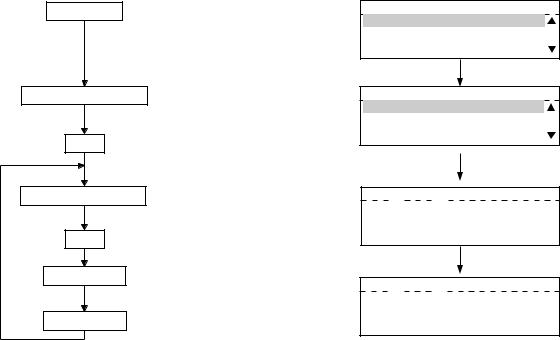
1.2.3 User test mode
When you press the PROGRAM key and enter the TEST mode from the menu, the items that can be
tested by the user are displayed.
(1)AUTO TEST
This mode allows the user to independently diagnose the machine by automatically performing a series of tests.
<Key used in operation>
Press the PROGRAM key
Use  or
or  keys
keys
Use  or
or  keys
keys
It takes about 2 minutes to finish TEST
<Display messages>
PROGRAM
01.DEFAURT SETTINGS 02.LISTS 03.INITIAL SETUP
TEST MODE 01.AUTO TEST
02.INDIVIDUAL TEST 03.TEST RESULT LIST
AUTO TEST
 -------------------
AUTO TEST
Completed
Calculates and compares the check sums of the firmware, function data and language information with the previously stored corresponding check sum values.
Same as Function Test.
Same as Function Test.
Same as Function Test.
Same as Function Test.
Same as Function Test.
Checks each part of the printer (fan, HVPS, polygon, heater, LSU) and prints one page of test pattern (not performed when there is no paper). Calculates and compares the check sum of the phonebook with the previously stored check sum value.
i) Network board test (with GF-1110)
e-STUDIO160/200/250 ADJUSTMENT ITEMS |
1 - 18 |
December 2002 TOSHIBA TEC |
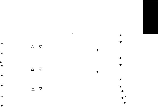
(2)INDIVIDUAL TEST
The user can perform a test in interactive mode and locate the faulty point from the test result. The test result is printed in the form of a report.
<Key used in operation> <Display messages>
|
|
|
|
PROGRAM |
|
|
|
Press the PROGRAM key |
PROGRAM |
|
|
|
|
||||||||||||||||||||||||||||||||||||||||||||||||||
|
|
|
|
|
|
|
|
01.DEFAURT SETTINGS |
|
|
|
|
|
|
|
|
|||||||||||||||||||||||||||||||||||||||||||||||
|
|
|
|
|
|
|
|
|
|
|
|
|
|
|
|
|
|
|
|
|
|
|
|
||||||||||||||||||||||||||||||||||||||||
|
|
|
|
|
|
|
|
|
|
|
|
|
|
|
|
02.LISTS |
|
|
|
|
|
|
|
|
|||||||||||||||||||||||||||||||||||||||
|
|
|
|
|
|
|
|
|
|
|
|
|
|
|
03.INITIAL SETUP |
|
|
|
|
||||||||||||||||||||||||||||||||||||||||||||
|
|
|
Select TEST MODE |
|
|
Use |
or |
keys |
|
|
|
|
|
|
|
|
|
|
|
|
|
|
|
|
|
|
|
|
|
|
|
|
|
|
|
|
|
|
|
|
|
|
|
|
|
|
|
|
|
|
|
|
|
|
|
|
|
||||||
|
|
|
|
|
|
|
|
|
|
|
|
|
|
|
|
|
|
|
|
|
|
|
|
|
|
|
|
|
|
|
|
|
|
|
|
|
|
|
|
|
|
|
|
|
|
|
|
|
|
|
|
|
|
||||||||||
|
|
|
|
|
|
|
|
|
|
|
|
|
|
|
|
|
|
|
|
|
|
|
|
|
|
|
|
|
|
|
|
|
|
|
|
|
|
|
|
|
|
|
|
|
|
|
|
|
|
|
|
|
|
|
|
|
|
|
|
|
|
||
|
|
|
|
|
|
|
|
|
|
|
|
|
|
|
|
|
|
|
|
|
|
|
|
|
|
|
|
|
|
|
|
|
|
|
|
|
|
|
|
|
|
|
|
|
|
|
|
|
|
|
|
|
|
|
|
|
|
|
|
|
|
|
|
|
|
|
|
|
|
|
|
|
|
|
|
|
|
|
TEST MODE |
|
|
|
|
||||||||||||||||||||||||||||||||||||||||||||
|
|
|
|
|
SET |
|
|
|
|
|
|
|
|
||||||||||||||||||||||||||||||||||||||||||||||||||
|
|
|
|
|
|
|
|
|
|
|
|
|
|
|
|
|
|
|
|
|
|
|
|
|
|
|
|
|
|
|
|
|
|
|
|
|
|
|
|
|
|
|
|
|
|
|
|
|
|
|
|
|
|
|
|
|
|
|
|
||||
|
|
|
|
|
|
|
|
|
|
|
|
|
|
|
01.AUTO TEST |
|
|
|
|
||||||||||||||||||||||||||||||||||||||||||||
|
|
|
|
|
|
|
|
|
|
|
|
|
|
|
02.INDIVIDUAL TEST |
|
|
|
|
|
|
|
|
||||||||||||||||||||||||||||||||||||||||
|
|
|
|
|
|
|
|
|
|
|
|
|
|
|
03.TEST RESULT LIST |
|
|
|
|
||||||||||||||||||||||||||||||||||||||||||||
|
|
|
|
|
|
|
|
|
|
|
|
|
|
|
|||||||||||||||||||||||||||||||||||||||||||||||||
|
Select INDIVIDUAL TEST |
Use |
or |
keys |
|
|
|
|
|
|
|
|
|
|
|
|
|
|
|
|
|
|
|
|
|
|
|
|
|
|
|
|
|
|
|
|
|
|
|
|
|
|
|
|
|
|
|
|
|
|
|
|
|
||||||||||
|
|
|
|
|
|
|
|
|
|
|
|
|
|
|
|
|
|
|
|
|
|
|
|
|
|
|
|
|
|
|
|
|
|
|
|
|
|
|
|
|
|
|
|
|
|
|
|
|
|
|
|
|
|
|
|
|
|
|
|
|
|
|
|
|
|
|
|
|
|
|
|
|
|
|
|
|
|
|
INDIVIDUAL TEST |
|
|||||||||||||||||||||||||||||||||||||||||||||||
|
|
|
|
|
SET |
|
|
|
|
|
|
|
|
||||||||||||||||||||||||||||||||||||||||||||||||||
|
|
|
|
|
|
|
|
|
|
|
|
|
|
|
|
|
|
|
|
|
|
|
|
|
|
|
|
|
|
|
|
|
|
|
|
|
|
|
|||||||||||||||||||||||||
|
|
|
|
|
|
|
|
|
|
|
|
|
|
01.ADF TEST |
|
|
|
|
|||||||||||||||||||||||||||||||||||||||||||||
|
|
|
|
|
|
|
|
|
|
|
|
|
|
|
02.KEY TEST |
|
|
||||||||||||||||||||||||||||||||||||||||||||||
|
|
|
|
|
|
|
|
|
|
|
|
|
|
|
|
|
03.LED LIST |
|
|
|
|
|
|||||||||||||||||||||||||||||||||||||||||
|
|
|
|
|
|
|
|
|
|
|
|
|
|
|
|
|
|
||||||||||||||||||||||||||||||||||||||||||||||
|
|
Select item to be tested |
|
Use |
or |
keys |
|
|
|
TEST MODE |
|
|
|||||||||||||||||||||||||||||||||||||||||||||||||||
|
|
|
|
|
|
|
|
|
|
04.LCD TEST |
|
|
|
||||||||||||||||||||||||||||||||||||||||||||||||||
|
|
|
|
|
|
|
|
||||||||||||||||||||||||||||||||||||||||||||||||||||||||
|
|
|
|
|
|
|
|
|
|
|
|
|
|
|
|
|
|
|
|
TEST MODE |
|
|
|||||||||||||||||||||||||||||||||||||||||
|
|
|
|
|
|
|
|
|
|
|
|
|
|
|
|
|
05.SPEAKER TEST |
|
|
|
|||||||||||||||||||||||||||||||||||||||||||
|
|
|
|
|
|
|
|
|
|
|
|
|
|
|
|
|
|
|
|||||||||||||||||||||||||||||||||||||||||||||
|
|
|
|
|
|
|
|
|
|
|
|
|
|
|
|
|
06.SWITCH TEST |
|
|
||||||||||||||||||||||||||||||||||||||||||||
|
|
|
|
|
SET |
|
|
|
|
Selected test is performed |
|
|
|
|
|||||||||||||||||||||||||||||||||||||||||||||||||
|
|
|
|
|
|
|
|
|
|
|
|
|
|
|
|
|
|
|
|
|
|
|
|
|
|
|
|
|
|
|
|
|
|
|
|
|
|
|
|
|
|
|
|
|
|
|
|
|
|
|
|
|
|
|
|||||||||
|
|
|
|
|
|
|
|
|
|
07.TEST PRINT |
|
||||||||||||||||||||||||||||||||||||||||||||||||||||
|
|
|
|
|
|
|
|
|
|
|
|
|
|
|
|
|
|
|
|
|
|||||||||||||||||||||||||||||||||||||||||||
|
|
|
|
|
|
|
|
|
|
|
|
|
|
|
|
|
|
|
|
|
|
|
|
|
|
|
|
|
|
|
|
|
|
|
|
|
|
|
|
|
|
|
|
|
|
|
|
|
|
|
|
|
|
|
|
|
|
|
|
|
|
|
|
|
|
|
|
|
|
|
|
|
|
|
|
|
|
|
|
|
|
|
|
|
|
|
|
|
|
|
|
|
|
|
|
|
|
|
|
|
|
|
|
|
|
|
|
|
|
|
|
|
|
|
|
|
|
|
|
|
|
|
|
|
|
|
|
|
|
|
|
|
CIS |
|
|
|
|
|
|
|
|
|
|
|
|
|
|
|
|
|
|
|
|
|
|
|
|
|
|
|
|
|
|
|
|
|
|
|
|
|
|
|
|
|
|
|
|
|
|
|
|
|
|
|
|
|
|
||||
|
|
|
|
|
|
|
|
|
|
|
|
|
|
|
|
|
|
|
|
|
|
|
|
|
|
|
|
|
|
|
|
|
|
|
|
|
|
|
|
|
|
|
|
|
|
|
|
|
|
|
|
|
|
|
|
|
|
|
|
|
|
|
|
Test Items |
|
|
|
|
|
|
|
|
|
|
|
|
|
|
|
|
|
|
|
|
|
|
|
|
|
|
|
|
|
|
|
|
|
|
|
|
|
|
|
|
|
|
|
|
|
|
|
|
|
|
|
|
|
||||||||||
|
|
|
a) ADF test |
Transports and ejects originals to check the transport system. Transports |
|||||||||||||||||||||||||||||||||||||||||||||||||||||||||||
|
|
|
|
|
|
|
|
|
|
|
and ejects a certain number of originals and displays the number of the |
||||||||||||||||||||||||||||||||||||||||||||||||||||
|
|
|
|
|
|
|
|
|
|
|
originals. The tester checks that this value matches the number of the origi- |
||||||||||||||||||||||||||||||||||||||||||||||||||||
|
|
|
|
|
|
|
|
|
|
|
nals. A transport speed can be selected with the resolution key. |
||||||||||||||||||||||||||||||||||||||||||||||||||||
|
|
|
b) Key test |
Press all the keys on the operation panel to check if they are detected nor- |
|||||||||||||||||||||||||||||||||||||||||||||||||||||||||||
|
|
|
|
|
|
|
|
|
|
|
mally. The key test ends when the STOP key is pressed in the end. If there is |
||||||||||||||||||||||||||||||||||||||||||||||||||||
|
|
|
|
|
|
|
|
|
|
|
any key which is not detected when pressed before the STOP key is pressed, |
||||||||||||||||||||||||||||||||||||||||||||||||||||
|
|
|
|
|
|
|
|
|
|
|
it will be judged to be an error. |
|
|
|
|
|
|
|
|
|
|
|
|
|
|
|
|
|
|
|
|
|
|
|
|
|
|
|
|
|
|
|
|
|
|
|
|
|
|
|
|
|
|
|
|
|
|
|
|
|
|||
|
|
|
c) LED test |
When the test is performed, all the LEDs will come on. If there is any LED |
|||||||||||||||||||||||||||||||||||||||||||||||||||||||||||
|
|
|
|
|
|
|
|
|
|
|
which is not lit when visually checked, it will be judged to be an error. |
||||||||||||||||||||||||||||||||||||||||||||||||||||
|
|
|
d) LCD test |
All the dots on the display go off (turn black). When the Start key is then |
|||||||||||||||||||||||||||||||||||||||||||||||||||||||||||
|
|
|
|
|
|
|
|
|
|
|
pressed, all the dots light (turn white). If there is any dot which does not light |
||||||||||||||||||||||||||||||||||||||||||||||||||||
|
|
|
|
|
|
|
|
|
|
|
or go off when visually checked, it will be judged to be an error. |
||||||||||||||||||||||||||||||||||||||||||||||||||||
|
|
|
e) Speaker test |
Check that the volume level from the speaker changes. |
|||||||||||||||||||||||||||||||||||||||||||||||||||||||||||
|
|
|
f) Sensor test |
Sensor test. |
|
|
|
|
|
|
|
|
|
|
|
|
|
|
|
|
|
|
|
|
|
|
|
|
|
|
|
|
|
|
|
|
|
|
|
|
|
|
|
|
|
|
|
|
|
|
|
|
|
|
|
||||||||
|
|
|
|
|
|
|
|
|
|
|
Open and close the covers by following the guidance appearing on the dis- |
||||||||||||||||||||||||||||||||||||||||||||||||||||
|
|
|
|
|
|
|
|
|
|
|
play. |
|
|
|
|
|
|
|
|
|
|
|
|
|
|
|
|
|
|
|
|
|
|
|
|
|
|
|
|
|
|
|
|
|
|
|
|
|
|
|
|
|
|
|
|
|
|
|
|
|
|
|
|
|
|
|
g) Printer test |
Checks the printer function by printing two test patterns. |
|||||||||||||||||||||||||||||||||||||||||||||||||||||||||||
December 2002 TOSHIBA TEC |
1 - 19 |
e-STUDIO160/200/250 ADJUSTMENT ITEMS |

(3)TEST RESULT LIST
Prints the results of (1) AUTO TEST and (2) INDIVIDUAL TEST.
<Key used in operation> <Display messages>
|
|
|
|
PROGRAM |
|
|
|
Press the PROGRAM key |
PROGRAM |
|||||||||||||||||||||||||||||||||||||
|
|
|
|
|
|
|
01.DEFAURT SETTINGS |
|
|
|
||||||||||||||||||||||||||||||||||||
|
|
|
|
|
|
|
|
|
|
|
|
|
|
|
|
|
||||||||||||||||||||||||||||||
|
|
|
|
|
|
|
|
|
|
|
|
|
|
02.LISTS |
|
|
|
|||||||||||||||||||||||||||||
|
|
|
|
|
|
|
|
|
|
|
|
|
|
03.INITIAL SETUP |
||||||||||||||||||||||||||||||||
|
|
|
|
|
|
|
|
|
|
|
|
|
|
|
|
|
|
|
|
|
|
|
|
|
|
|
|
|
|
|
|
|
|
|
|
|
|
|
|
|
|
|
|
|
|
|
|
|
|
|
|
|
|
|
|
|
|
|
|
|
|
|
|
|
|
|
|
|
|
|
|
|
|
|
|
|
|
|
|
|
|
|
|
|
|
|
|
|
|
|
|
|
|
|
|
|
|
|
|
|
|
|
|
|
|
|
|
|
|
|
|
|
|
|
|
|
|
|
|
|
|
|
|
|
|
|
|
|
|
|
|
|
|
|
|
|
|
|
|
|
|
|
|
Select TEST MODE |
|
|
Use |
or |
keys |
|
|
|
|
|
|
|
|
|
|
|
|
|
|
|
|
|
|
|
|
|
|
|
|
|
|
|
|
|
|
|
|
|
|||||
|
|
|
|
|
|
|
|
|
|
|
|
|
|
|
|
|
|
|
|
|
|
|
|
|
|
|
|
|
|
|
|
|
|
|
|
|
|
|||||||||
|
|
|
|
|
|
|
|
|
|
|
|
|
|
TEST MODE |
||||||||||||||||||||||||||||||||
|
|
|
|
|
|
|
|
|
|
|
|
|
|
|
|
|
|
|
|
|
|
|
|
|
|
|
|
|
|
|
|
|
|
|
|
|
|
|
|
|
|
|
|
|
|
|
|
|
|
|
|
|
|
|
|
|
|
|
|
|
|
01.AUTO TEST |
|||||||||||||||||||||||||||||||
|
|
|
|
|
|
|
|
|
|
|
|
|
|
02.INDIVIDUAL TEST |
||||||||||||||||||||||||||||||||
|
|
|
|
|
SET |
|
|
|
|
|
|
|
||||||||||||||||||||||||||||||||||
|
|
|
|
|
|
|
|
|
|
|
|
03.TEST RESULT LIST |
|
|
|
|||||||||||||||||||||||||||||||
|
|
|
|
|
|
|
|
|
|
|
|
|
|
|
|
|
|
|
|
|
|
|
|
|
|
|
|
|
|
|
|
|
|
|
|
|
|
|
|
|
|
|
|
|
|
|
|
|
|
|
|
|
|
|
|
|
|
|
|
|
|
|
|
|
|
|
|
|
|
|
|
|
|
|
|
|
|
|
|
|
|
|
|
|
|
|
|
|
|
|
|
|
|
|
|
|
|
|
|
|
|
|
|
|
|
|
|
|
|
|
|
|
|
|
|
|
|
|
|
|
|
|
|
|
|
|
|
|
|
|
|
|
|
|
|
|
|
|
|
|
|
|
|
|
|
|
|
|
|
|
|
|
|
|
|
|
|
|
|
|
|
|
|
|
|
|
|
|
|
|
|
|
|
|
|
|
|
|
|
|
|
|
|
|
|
|
|
|
Select TEST RESULT LIST |
Use |
or |
keys |
TEST RESULT LIST |
|||||||||||||||||||||||||||||||||||||||||
|
|
|
|
|
|
|
|
|
|
|
|
|
|
|
|
|
|
|
|
|
|
|
|
|
|
|
|
|
|
|
|
|
|
|
|
|
|
|
|
|
|
|
|
|
|
|
|
|
|
|
|
|
|
|
|
|
|
|
|
|
Printing accepted |
||||||||||||||||||||||||||||||||
|
|
|
|
|
SET |
|
|
|
|
|||||||||||||||||||||||||||||||||||||
|
|
|
|
|
|
|
|
|
|
|
|
|
|
|
|
|
|
|
|
|
|
|
|
|
|
|
|
|
|
|
|
|
|
|
|
|
|
|
|
|
|
|
|
|
|
|
|
|
Print TEST RESULT LIST |
|
|
|
|
|
|
|
|
|
|
|
|
|
|
|
|
|
|
|
|
|
|
|
|
|
|
|
|
|
|
|
|
|
|
|
|
|
|||||||
|
|
|
|
|
|
|
|
|
|
|
|
|
|
|
|
|
|
|
|
|
|
|
|
|
|
|
|
|
|
|
|
|
|
|
|
|
|
|
|
|
|
|
|
|
|
|
If there is any NG in the RESULT column, the corresponding test is problematic. An test with an asterisk (*) cannot be executed unless the corresponding option is installed.
e-STUDIO160/200/250 ADJUSTMENT ITEMS |
1 - 20 |
December 2002 TOSHIBA TEC |

1.2.4 Function test
The function test checks each function of the copier. To enter the function test mode, follow the procedure below, or enter the Service mode (*,#,*,*) and select the menu for the function test
<Key used in operation> <Display messages>
|
1 |
|
|
3 |
|
Power ON |
|
FUNCTION TEST |
||||||||||||||||||||||||||||||||||||
|
|
|
|
|
|
|
|
|
|
|
|
|
|
|
|
|
|
|
|
|
|
|
|
|
|
|
|
|
|
|
|
|
|
|
|
|
||||||||
|
|
|
|
01.OPE.PANEL TEST |
|
|
|
|||||||||||||||||||||||||||||||||||||
|
|
|
|
|
|
|
|
|
|
|
|
|
|
|||||||||||||||||||||||||||||||
|
|
|
|
|
|
|
|
|
|
|
|
|
02.PRINT TEST |
|
||||||||||||||||||||||||||||||
|
|
|
|
|
|
|
|
|
|
|
|
|
03.MODEM TEST |
|||||||||||||||||||||||||||||||
|
|
|
|
|
|
or |
|
Select test menu |
|
|
|
|
|
|
|
|
|
|
|
|
|
|
|
|
|
|
|
|
|
|
|
|
|
|
|
|
|
|
|
|
||||
|
|
|
|
|
|
|
|
|
|
|
|
|
|
|
|
|
|
|
|
|
|
|
|
|
|
|
|
|
|
|
|
|
|
|
|
|
|
|
|
|
|
|
|
|
|
|
|
|
|
|
|
|
|
|
|
|
|
|
|
|
|
|
|
|
|
|
|
|
|
|
|
|
|
|
|
|
|
|
|
|
|
|
|
|
|
|
|
|
|
SET
The following tests can be conducted in the Function test mode. 01. OPE. PANEL TEST
02. PRINT TEST
03. MODEM TEST *1 (Factory test)
04. SENSOR TEST
05. SRAM TEST
06. DRAM TEST
07. CLOCK IC TEST
08. SCANNER TEST
09.CODEC TEST
10.OUTPUT TEST
11.PRINTER BOARD TEST *2
*1: |
When the FAX kit (GD-1061) is not installed, the test is not present. |
*2: |
When the PCL kit (GA-1031) is not installed, the test is not present. |
December 2002 TOSHIBA TEC |
1 - 21 |
e-STUDIO160/200/250 ADJUSTMENT ITEMS |

(1) 01. OPE PANEL TEST
This test checks the control panel display. When any key other than START and CLEAR/STOP is pressed during the display test, O and X are displayed alternately in the lower right of the display.
<Key used in operation>
1 
 3
3 
 Power ON
01.OPE. PANEL TEST Select test menu
SET All display dots keep turning on and off alternatery for one second each. (All LEDs turn on.)
<Display messages>
FUNCTION TEST 01.OPE.PANEL TEST 02.PRINT TEST 03.MODEM TEST
START |
Cancel |
The cursor moves (from the upper left to the lower right).
|
|
|
|
|
|
|
|
|
|
|
|
|
|
|
|
|
|
|
|
|
|
|
|
|
|
|
|
|
|
|
|
|
|
|
|
e-STUDIO160/200/250 ADJUSTMENT ITEMS |
1 - 22 |
|
|
|
|
|
|
|
|
|
|
|
|
|
|
December 2002 TOSHIBA TEC |
|||||||||||||||||||
Loading...