

Page 1

Optional add-on cassette
F10M option unit Instruction manual
E6580772③
NOTE
1. Make sure that this instruction manual is delivered to the end user of the the F10M
option unit.
2. Read this manual before installing or operating the inverter unit, and store it in a safe
place for reference.
(C)TOSHIBA Corporation 1999
All Rights Reserved.
Page 2
E6580772③
Safety Precautions
On the inverter and in its instruction manual, important information is contained for preventing injuries to users
and damages to assets and for proper use of the device. Read the instruction manual attached to the inverter
along with this instruction manual for completely understanding the safety precautions and adhere to the
contents of these manuals.
Handling in general
Danger
▼Never disassemble, modify or repair the inverter.
Never
Disassemble
Prohibited
Mandatory
Disassembling the inverter could cause electric shocks, fire or injuries.
Request your TOSHIBA dealer for repairs.
▼Do not remove connectors when the power is on.
It could lead to electric shocks.
▼ Do not put or insert foreign objects such as waste cable, bars, or wires into the inverter.
It could lead to electric shocks or fire.
▼Do not splash water over the inverter.
It could lead to electric shocks or fire.
▼Wiring should be conducted after turning the inverter power off.
▼Turn off the power immediately in case any abnormalities such as smokes, smells or
abnormal noise are found.
Neglect of these conditions could lead to fire.
Ask your TOSHIBA dealer for repairs.
Transportation and Installation
▼Do not install or operate the inverter if it is damaged or any part is missing from it.
Operating the inverter in a defective condition could lead to electric shocks or fire.
Ask your TOSHIBA dealer for repairs.
▼Do not put any inflammable material near the inverter.
Prohibited
Mandatory
It could catch fire if the inverter sparks because of a breakdown and the like.
▼Do not install the inverter where it could be splashed with water and the like.
It could lead to electric shocks or fire.
▼
Inverter must be used under environmental conditions prescribed in this
instruction manual.
Using the inverter under conditions not specified by the instruction manual could lead
to breakdown.
Danger
1
Page 3
E6580772③
Warning
▼Do not install the inverter in any place subject to vibrations or it could fall.
Prohibited
Wiring
Mandatory
About operation
Otherwise it can cause injury to people.
Danger
▼ Be sure to perform the following preparatory work before proceeding to wiring.
①Turn the power off.
Wait 10 minutes or more after turning the power off and confirm that the charge lamp
(on the inverter) is extinct.
②Using a circuit tester that has a D.C. voltage measuring capacity of more than
800V, check to see that the voltage remaining in the D.C. main circuit (between PC
and PA) is below 45V.
Failure to do this preparation could lead to electric shocks.
▼Tighten the terminal board fixing screws at the specified torque.
Failure to do this could lead to fire.
▼Do not touch inverter terminals when they are energized even if the motor is halted.
Touching terminals while the power is energized could lead to electric shocks.
▼Do not wipe the body with a wet cloth.
Prohibited
About disposal of Inverter
Mandatory
It could lead to electric shocks.
▼Do not pull on the cable
It could cause damage or error.
▼Dispose of the inverter as an industrial waste.
Unless it is disposed of as an industrial waste, it will become risks for human
injury.
Danger
Warning
2
Page 4

E6580772③
Introduction
Thank you for purchasing the “F10M option unit” for industrial inverter TOSVERT VF-A7 and later series.
Read this manual carefully before using the unit.
Keep this manual near at hand of the operator who uses the “F10M option unit” for future reference in the
maintenance and inspection.
For details of handling, it is requested to have the following instruction manuals.
TOSLINE-F10M communication function manual (E6580773)
•
This manual describes the communication function and its use of TOSLINE-F10M.
Serial communication function manual (E6580793)
•
This manual describes the details of transmission command.
<<<< Type of F10M option unit >>>>
TLF 001 Z −0
Revision number
Without cable
Model number of F10M option
F10M option
<<<< Confirmation on accessories >>>>
Following accessory parts are included in the F10M option unit.
Upon unpacking, confirm on the following items.
F10M option unit
(1) Instruction manual of F10M option unit (this manual) : one
(E6580772)
M
A
N
U
A
L
(2) Board for connecting options
(3) Terminal resistor (1/2W-120Ω)
3
Page 5

E6580772③
Contents
1. NAME AND FUNCTION OF EACH SECTION .......................................................... 5
1.1 Appearance ...........................................................................................................................................5
1.2 Name of each section (terminal) ...........................................................................................................6
2. CONNECTION TO THE INVERTER......................................................................... 7
2.1 Connection to the inverter .....................................................................................................................7
2.2 Wiring ....................................................................................................................................................9
3. FUNCTIONAL DESCRIPTION................................................................................ 10
3.1 F10M communication function ............................................................................................................10
3.1.1 Connection of transmission cable.................................................................................................10
3.1.2 Setting of communication parameters..........................................................................................11
3.1.3 Communication parameters .........................................................................................................12
3.2 Vector control with sensor ...................................................................................................................15
3.2.1 PG input setting ............................................................................................................................15
3.2.2 Connection of PG .........................................................................................................................16
3.2.3 Selection of encoder type .............................................................................................................18
3.2.4 Vector control setting parameter ..................................................................................................19
3.2.5 Monitoring method for feedback amount......................................................................................21
3.2.6 Accuracy of speed control ............................................................................................................21
4. EXTERNAL DIAGRAM............................................................................................ 22
5. SPECIFICATION..................................................................................................... 23
6. WARRANTY ........................................................................................................... 25
4
Page 6
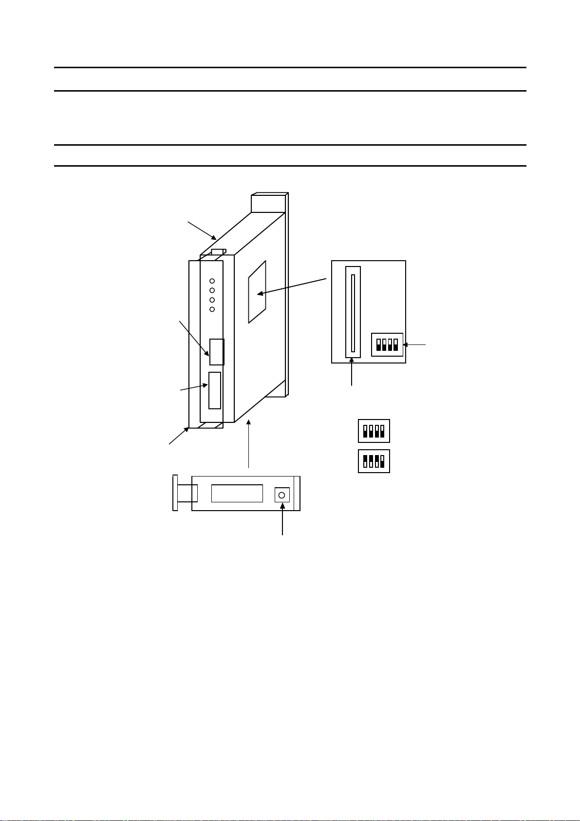
1. Name and function of each section
Following figure shows appearance and name of each section of the F10M option unit.
1.1 Appearance
Inverter connecting side
Connector (left side)
View when the cover is removed
TB1 detachable terminal
block Phoenix
MSTBT2.5/4-ST-5.08
E6580772
Bit switch for
PG input
③
TB2 detachable terminal
block Phoenix
MC1.5/8-ST-3.81
Terminal block cover
Connector for options
Without PG input
With PG input
Grounding terminal
M3 screw terminal
5
Page 7
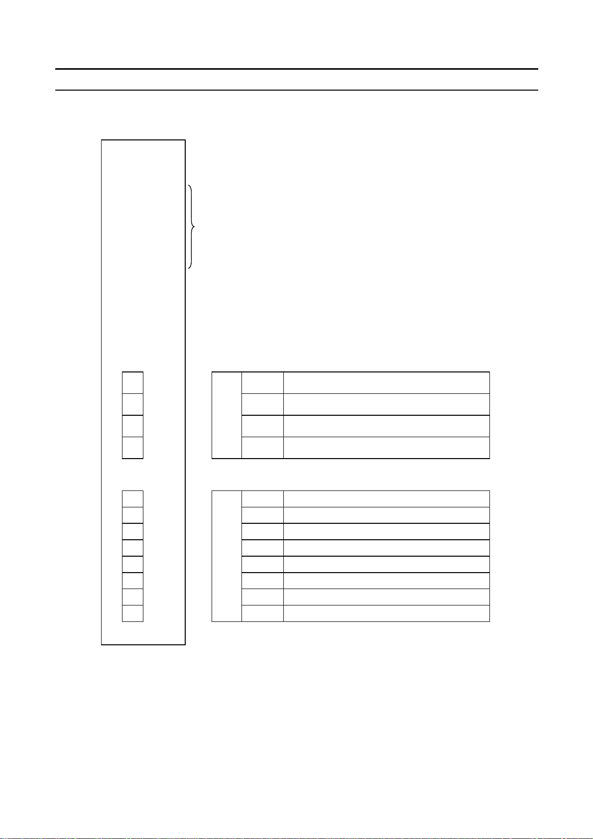
1.2 Name of each section (terminal)
TLF001Z
○
RUN
○
SCAN
○
AUX
○
POWER
LED for status display
E6580772
③
1 SL1 SL1 Transmitting and receiving data (positive)
2 SL2 SL2 Transmitting and receiving data (negative)
TB1
3 SG SG Signal ground
4SHD
1 PGA1 PGA1 Phase A, PG feedback anode side
2 PGA2 PGA2 Phase A, PG feedback cathode side
3 PGB1 PGB1 Phase B, PG feedback anode side
4 PGB2 PGB2 Phase B, PG feedback cathode side
5 PGZ1 PGZ1 Phase Z, PG feedback anode side
6 PGZ2 PGZ2 Phase Z, PG feedback cathode side
7 PGVC PGVC 12V power supply
8PGCC
*
SHD Terminal for shield (no connection inside)
TB2
PGCC Common terminal for control signal *1
1: Connect this PGCC terminal to the CC terminal on the
control board of the inverter.
6
Page 8
E6580772
2. Connection to the inverter
Connect the F10M option unit to the inverter according to the procedures below.
2.1 Connection to the inverter
(1) Confirm that the all power to the inverter are turned off beforehand.
Note: Wait 10 minutes or more after turning the power off and confirm that the
charge lamp on the inverter is unlit.
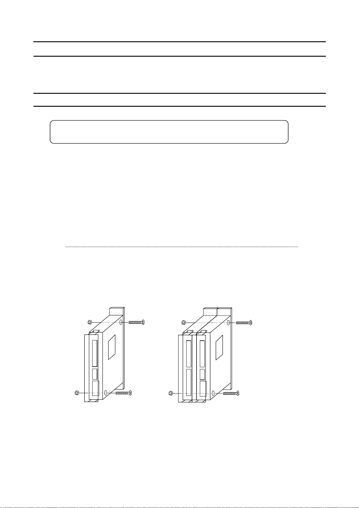
(2) Fixing the F10M option unit alone by using screws
<<<<When the unit is installed alone>>>>
Tighten M4x25 screws with M4 nuts to an attachment of optional add-on cassette (separately procured)
to fix the unit as shown in the figure below.
<<<<When the unit is installed with another option>>>>
③
Read instructions of ‘connection with options’ on the following page for installation. Same procedures
apply when three options are installed together.
(When plural options are installed, order of installation from the inverter side is not specified.)
(Note) Determine the initial setting of the bit switch for internal signal before connecting options.
Mount a board for option connection, then use M4x50 screws and M4 nuts to fix the options as shown
below.
(When three units of option are installed, use M4x75 screws.)
(3) Fixing the unit to the inverter
Method for fixing the unit to the inverter differs according to the type of inverter to which the unit is
installed. Refer to the instruction manual of “Attachment of optional add-on cassette”.
7
Page 9

E6580772
Connection with options
When two or more optional add-on cassettes are used, connect them with reference to the following
diagram.
Mounting of relay board for connecting options
①
Following the diagram below mount the board which is attached to the F10M option unit onto the unit for
connecting options.
Insert a flat head screwdriver into the triangular section at
the right side of the option unit and remove the small
window cover.
Slide the relay board into the place according to
the insertion guide.
(Note) Engage the patterned section of the board
Relay board
mounting guide
Triangular mark on
the side face
with the metal pad section of the connector and
insert the board in parallel. When the insertion
angle inclines, remove the board once and try
again.
③
Engage the patterned
section of the board with
the metal pad section of
the connector and insert
the board in parallel.
Connecting two options
②
Connect options with reference to the diagram below.
Triangular mark on the side face
When the metallic parts of the relay
board is touched with bear fingers,
they oxidizes and the contacting
failure occurs. Put on gloves for the
work.
Fit two option’s positioning guides on
both units and connect two units not to
shift the connecting position of the relay
board. Hold a triangular section on the
side of the unit and engage the relay
boards securely.
(Connection is satisfactory when the
click sound can be heard.)
If there is a gap between the units, two
boards are misaligned. Carry out the
work again from the beginning.
Option’s positioning guide (two guides on top and bottom)
8
Page 10

2.2 Wiring
When conduct wiring, follow the instructions below.
•
Use shield wire for control signal line and ground the unit with shield wire.
•
Applicable wire size for TB1 is 0.2 to 2.5mm2.
For TB2, it is 0.2 to 1.5mm
•
Peel off the end of the wire by about 5mm (7mm for TB1).
•
For connecting wires, use screwdriver that has a blade tip of 0.4mm thickness and 2.5mm width.
(For TB3, thickness and width should be 0.6mm and 3.5mm.)
•
Tightening torque of the terminal block should be 0.22 to 0.25N・m .
2
.
E6580772
③
(For TB1, it is 0.5 to 0.6N
•
Never bind the signal line and main circuit connection wire together.
・
m.)
Separate the signal line and the main circuit connection wire by more than 200mm.
•
Use 0.75mm2 wire for the connection of PGCC terminal of the option side and CC terminal of the inverter.
•
Use 0.75mm2 wire for the connection of grounding terminal of the option side and that of the inverter.
< PG interface > [ TB2 terminal]
Terminal
name
PGA1
PGA2
PGB1
PGB2
PGZ1
PG feedback input,
Pulse row speed
command input
(Phase A input)
PG feedback input
Pulse row speed
command input
(Phase B input)
PG feedback input
Pulse row speed
Function Specification Internal circuit
PG feedback
•
15V complementary / open
collector
•
12V complementary / open
collector
•
Maximum input frequency
60kpps (2 phases)
120kpps (single phase)
•
Pulse duty
50 ± 10%
PGA1
PGB1
PGZ1
PGA2
PGB2
PGZ2
470 Ω
470 Ω
Photocoupler
V
:1.2~1.7V
F
command input
PGZ2
(Phase Z input)
PGVC
PGCC
PG power supply terminal 12VDC
160mA or less
9
Page 11

E6580772
M
③
3. Functional description
In this section, functions added by the installation of this F10M option unit, on top of the standard inverter
functions, are described.
3.1 F10M communication function
Through the communication network, drive and stop control and concentrated monitoring control of operation
status can be carried out by the programmable controller and industrial computer.
3.1.1 Connection of transmission cable
z SL1, SL2, SG
Transmission path is constructed by the shielded twisted pair cables as shown in the figure below.
Be sure to connect SL1, SL2 and SG mutually to another station. Note that wrong connection will not bring the
correct transmission.
z SHD
Connect a shield of twisted pair cable to the transmission terminal SHD of each station and set up a class 3 or
equivalent grounding work in an arbitrary station.
z Terminal resistor
Set terminal resistors at both sides of the system for the sake of impedance matching. Connect terminal
resistor (120Ω-1/2W) between the terminal block SL1 and SL2.
(As for the master station (MS), terminal resistor can be combined by connecting L1 and TERM.)
Shielded twisted pair cable
MS
TER
L1
L2
SG
FG
Grounding / Earthing
(Grounding / earthing resistance 100Ωmax.)
TLF001Z TLF001Z TLF001Z
SL1
SL2
SG
SHD
SL1
SL2
SG
SHD
SL1
SL2
SG
SHD
Terminal resistor
120Ω-1/2W
Connection of communication cable of TOSLINE F10M
Signal name Name Detail
SL1 Transmitting and receiving data Positive line
SL2 Transmitting and receiving data Negative line
SG Signal ground Ground of signal line
•
Do not connect a grounding line of the shield and a power line earth of the inverter or so.
•
Separate a transmission cable from the main circuit connection wire by more than 200mm.
10
Page 12

E6580772
③
3.1.2 Setting of communication parameters
To enable F10M communication, set following parameters to the inverter. The parameters will be validated by
rebooting a power supply or changing a reset setting (f899) to1.
When interrupting a transmission to change the setting of command input, reboot a power supply if necessary,
since the data which have been received before the interruption of transmission are stored in the inverter.
cmod Operation command mode selection
fmod Speed setting mode selection
f802 Inverter number
f830 Data type selection
(Set this parameter to 4 to carry out run/stop with F10M communication.)
(Set this parameter to 9 to execute frequency command with F10M communication.)
f831 Input reference setting 1
f832 Input reference setting 2
f833 Input reference setting 3
f834 Input reference setting 4
f835 Input reference setting 5
f836 Input reference setting 6
f841 Monitor output setting 1
f842 Monitor output setting 2
f843 Monitor output setting 3
f844 Monitor output setting 4
f845 Monitor output setting 5
f846 Monitor output setting 6
f850 Communication error selection
f851 Communication error detecting time
f899 Reset function (1 to reset)
11
Page 13

3.1.3 Communication parameters
F10M communication parameters
Parameter name Title Setting value Details
Inverter number
Data type
selection
Input reference
setting 1
Input reference
setting 2
Input reference
setting 3
Input reference
setting 4
Input reference
setting 5
Input reference
setting 6
Monitor output
setting 1
Monitor output
setting 2
Monitor output
setting 3
Monitor output
setting 4
Monitor output
setting 5
Monitor output
setting 6
f802
f830
f831
f832
f833
f834
f835
f836
f841
f842
f843
f844
f845
f846
0 to 255 Sets inverter station address. (Note 1)
When using a message transmission, set the address of the
master station to 0 and address of the inverter station to 1 or
over.
0, 1 Selects type of transmitting and receiving data.
0: VFA7 mode
1:μs 250 m ode
0 to 16 Sets scan transmission data to be received.
0: Without setting
1: Command
2: Speed reference value
3: Auxiliary speed reference value
4: Torque limit value
5: Positive torque limit value
6: Negative torque limit value
7: Torque command value
8: Synchronized torque bias
9: Tension torque bias
10: Load sharing gain
11: Drooping gain
12: Speed loop proportional gain
13: Speed loop accumulative gain
14: Terminal output data
15: Inertia moment ratio
16: Expansion command
0 to 16 Sets scan transmission data to be sent.
0: Without setting
1: Status
2: Operation frequency
3: Speed feedback value (real time)
4: Speed feedback value (1-second filter)
5: Internal torque reference value
6: Output amperage
7: Exciting amperage
8: Torque amperage
9: Overload accumulative value
10: Deleted torque of acceleration/deceleration torque
11: Motor counter data
12: Error code
13: Input terminal data
14: VI input
15: RR input
16: RX input
E6580772
③
12
Page 14

Parameter name Title Setting value Details
Com. Error
selection
Com. Error
detecting time
Reset function
f850
f851
f899
0 to 4 Sets the inverter operation at time of communication error.
The action of inverter will be different depending on the
status (during operation or halt) of the inverter. (Note 2)
0: During halt Inverter stops after free run.
During operation Inverter trips.
1: During halt Inverter stops after free run.
During operation Inverter stops after free run.
2: Invalid (Setting is enabled with F10M
3: During halt Inverter decelerates to stop.
During operation Inverter decelerates to stop.
4: During halt Inverter continues to run.
During operation Inverter continues to run.
0 to 1000 Sets the time until the communication error is detected.
Setting is done by a unit of ms. (Note 3)
0, 1 Resets the inverter station.
0: No action
1: To reset the inverter station. After resetting, setting
data returns to 0.
E6580772
option connected.)
③
(Note 1) For setting the parameters, never duplicate the station address on the same communication line.
PLC rink relay register is automatically allocated according to the setting of the station address. As for the
setting of station addresses, consider the allocation of rink relay register that is determined by the other
station addresses and the number of words that have been set in the parameters f831 to f836, and
f841 to f846.
The maximum setting value for station address is 255, however when 255 is set, only one word of scan
data can be set. To set the scan data in its maximum value of 12 words, setting value of the station
address should be: 255-(12-1)= 244.
(Note 2) Setting of “free-run stop” is valid when the “operation command mode selection” [cmod] is
selected to the optional add-on cassette.
Setting of “deceleration stop” is valid when the “operation command mode selection” [cmod] is selected
to the optional add-on cassette or when the “speed setting mode selection” [fmod] is selected to the
optional add-on cassette. At the same time the deceleration stop returns the command of run/stop and the
speed reference value to 0. Except when the above command setting is selected, inverter cannot be
stopped.
Furthermore when the “operation command mode selection” [cmod] is set to other than the optional
add-on cassette and when the “speed setting mode selection” [fmod] is selected to the optional add-on
cassette, in some cases inverter can not stop running because of the setting of the parameters (zero-
speed operation setting). Torque control is valid when the “operation command mode selection” [cmod]
is set to the optional add-on cassette, but the inverter operation becomes “free-run stop” at that time.
13
Page 15

E6580772
Continuous operation depends on the status information that was before the communication error happens.
z
Display of communication error will be [t].
z
Display of trip will be [err8].
z
When interrupting a transmission to change the setting of command input, reboot a power supply if
necessary, since the data which have been received before the interruption of transmission are stored in
the inverter.
z
Parameter setting of smaller communication number will be valid in case that the same setting values are
allocated to the command input setting which are between 1 and 6, and also to the monitor output setting
between 1 and 6.
(Note 3) The setting of communication error detection time is relating to the number of stations connected
to the communication line. W hen changing the setting, fully consider the number of connected stations.
Other parameters
③
The following parameters reflect the transmitted data in the control of the inverter.
Parameter name Title Setting value Details
Operation
command mode
selection
Speed setting
cmod
fmod
4
9
Validates the command sent from the F10M option.
Operation such as run/stop from the other station will be
possible.
Validates the speed reference value from the F10M option.
mode selection
Torque command
f420
9
Validates the torque command value from the F10M option.
selection
Selection of
synchronized
f422
5
Validates the synchronized torque bias from the F10M
option.
torque bias input
Selection of
f423
5
Validates the tension torque bias from the F10M option.
tension torque
bias input
Load sharing gain
f424
5
Validates the load sharing gain from the F10M option.
input selection
Power running
f440
5
Validates power running torque limit from the F10M option.
torque limit 1
selection
Selection of
f442
5
Validates regenerative torque limit from the F10M option.
regenerative
torque limit 1
14
Page 16

E6580772
123
4
③
3.2 Vector control with sensor
Using the pulse-train feedback signal from the encoder installed on the motor shaft or load rotation shaft,
vector control with sensor can be conducted.
Speed control operation :150% torque at 0 speed, speed control range 1:1000 (1000 ppr PG)
speed accuracy ±0.02% (50Hz base digital input)
Torque control operation :Torque control accuracy: ±10%
(torque control range: –100% to 100%)
3.2.1 PG input setting
To carry out PG feedback with this F10M option, it is necessary to set the bit switches of the PG input selection.
To select the PG input, open the small window cover on the right side of the option (use flat head screwdriver
and the like) and set the position of the bit switches as shown in the figure below.
When the cover is removed.
Bit switch for PG
Without PG: Set all to OFF. (default setting)
With PG: Set No.1, 2 and 3 to ON.
(Note) When using the PG feedback together with the vector option (VEC001Z), connect PG input to the
vector option side and set all the bit switches of the PG input to OFF. If the setting of the bit switches is
kept to “With PG” and the PG feedback is used together with the vector option, there is a possibility of
malfunction in the PG feedback circuit and also the unit may be broken.
15
Page 17

E6580772
3.2.2 Connection of PG
As for the pulse input signals, PGA1 and PGA2 are connected for Phase A, PGB1 and PGB2 are
connected for Phase B, and PGZ1 and PGZ2 are connected for Phase Z.
(The wiring for Phase Z is done only when using Z-marker is necessary.)
The polarity of the pulse input signals should be as follows:
+ side: PGA1, PGB1, PGZ1 - side: PGA2, PGB2, PGZ2
The signal which is fed back from the encoder should have the waveform of the figure below in
terms of the direction of motor rotation. The encoder installation direction and signal wiring
should be done accordingly.
★★★★
Forward rotation or reverse rotation is judged from the feedback pulses of Phase A and Phase B
(2-phase pulse that have 90 degrees of phase difference). Therefore, it should be noted that,
when connections are wrong, there is possibility for abnormal rotation of the motor.
③
Phase A(VA)
Forward rotation
Phase B(VB)
PGA1
PGA2
PGB1
PGB2
Judgement on normal and reverse rotations by the PG feedback
of two phases (Phases A and B)
<When PG feedback signal is single phase>
1. For PG feedback signal, connect terminals PGA1 and PGA2.
2. The judgement on forward rotation and reverse rotation is impossible.
Only the speed control mode is applicable.
A
↑V
A
A
B
B
↑V
B
Phase A(VA)
Reverse rotation
Phase B(VB)
PG
Phase difference:Xn≧0.15T(n=1,2,3,4)
X
X
X3X
2
1
4
T
16
Page 18

A
ABB
Inverter
1
2
1
2
C
2
C
A
B
c
cVcc
1
2
1
2
C
C
2
E6580772
③
Free run is stopped when OFF.
Forward rotation with ON and
reduce speed and stop with OFF
Reverse rotation with ON and
reduce speed and stop with OFF.
When both forward and reverse
rotation is ON, reverse rotation.
(In case that
cmod=0
)
Connect PGCC of option unit
and CC of inverter.
Example of complementary encoder connection
R
S
T
ST
F
R
CC
U
IM
TB
PGA
PGA
PGB
PGB
PGV
PGC
V
W
E
Vcc
0V
When single phase, connect
EE
terminals PGA1 and PGA2
only.
Free run is stopped when OFF.
Forward rotation with ON and
reduce speed and stop with OFF
Reverse rotation with ON and
reduce speed and stop with OFF.
When both forward and reverse
rotation is ON, reverse rotation.
In case that cmod=0
(
)
Connect PGCC of option unit
and CC of inverter.
Example of open collector encoder connection
Inverter
R
S
T
ST
F
R
CC
EE
TB
PGA
PGA
PGB
PGB
PGV
PGC
U
V
W
E
Vc
Vc
0V
IM
When single phase, connect
terminals PGA1 and PGA2
17
Page 19

E6580772
★ Caution in case of using open collector encoder connection
In case using pulse command oscillator and open collector encoder, the rise time of the voltage when the
transistor is OFF tends to be longer than the fall time at the time when the transistor is ON. Therefore, if the
maximum input frequency becomes higher, the pulse duty cannot maintain the 50±10% specification.
Conduct derating on the maximum input frequency so that the pulse duty will be within the following
specification range.
<Derating computation formulae of open collector’s maximum input pulse frequency >
0.8/(Maximum input frequency x A) – Voltage rise time ≧ 3 x 10
A : (single phase input: 2) (two-phase input: 4)
Voltage rise time = Encoder exclusive pulse rise time + R x C
Encoder exclusive pulse rise time (s) : Please inquire at the encoder manufacturer.
R (Ω) (Input resistance) : internal resistance 1000(Ω)+external resistance value
(In case there is external resistance)
C(F) (Cable static capacity) : Please inquire at the cable manufacturer.
<Example>
Encoder : LBJ-005-500 (SUMTAK), 2-phase input
Encoder pulse rise time : 0.35 x 10⁻⁶(s)
Cable : ROVV-SB-0.2-5P-10m (Furukawa Electric Co., Ltd)
Static capacity : 120 x 10
–12
(F/m) x 10 (m)
–6
…..①
③
From Formulae①
0.8/(Maximum input frequency x A) – Voltage rise time ≧ 3 x 10
Voltage rise time = (0.35 x 10
= 1.55 x 10
–6
) + 1000 x (120 x 10
-6
-12
x 10)
–6
[Maximum input frequency] ≦87912 (Pulse/s) [Single phase input]
≦43956 (Pulse/s) [Two-phase input]
3.2.3 Selection of encoder type
The encoder type should be selected, following the table below.
Encoder Type Characteristics Maximum Wiring Length
Rated voltage output with emitter/follower
combination.
Complementary
Open Collector
High anti-nose characteristics. High-speed response.
Long-distance transmission capability.
Need to pay attention to waveform irregularity.
The collector of the transistor is output directly.
Low anti-noise characteristics. Low-cost.
Need to pay attention to waveform irregularity and
distortion.
100m
10m
18
Page 20

E6580772
③
3.2.4 Vector control setting parameter
During operation with vector control with sensor, it is necessary to set the following parameters shown in the
table below.
<Basic parameters>
Title
pt
When conducting vector control with sensor (speed/torque control) with this F10M option unit is added, pt=8
should be set.
For torque control operation, it is necessary to allocate control switching (torque/position) to one of the terminal
function selection f110 to f118 (input terminal selection 1 to 8) (cmod =0) or to set operation
switching by communication system (cmod = 2 to 4) in addition to the above parameters.
For details of adjustment methods by the speed control command and torque control command, refer to the
inverter’s instruction manual.
Title Function Name Parameter Setting Setting at Shipment
f367
f368
f374
f375
f376
f377
f400
f401
f402
f403
f404
f405
f410
f411
f412
f413
Function
Name
Motor control
mode
selection
Number of PG input pulse
Selection of number of PG input phases 1: Single phase input
Current control proportional gain
Current control integral gain
Speed loop proportional gain
0: Constant torque
1: Variable torque mode
2: Automatic torque boost
3: Sensorless vector control (speed)
4: Automatic torque boost + automatic energy-saving
5: Sensorless vector control (speed) + automatic energy-saving
6: V/F 5-points setting
7: Sensorless vector control (speed/torque switching)
8: PG feedback vector control (speed/torque switching)
9: PG feedback vector control (speed/position switching)
Speed loop integral gain
Auto tuning 0: No auto tuning (internal table)
Slip frequency gain
Motor constant 1
Motor constant 2
Motor constant 3
Motor constant 4
Motor constant 5
Number of poles of motor 2, 4, 6, 8, 10, 12, 14, 16 4
Rated capacity of motor
Motor type 0: TOSHIBA Standard Motor 1
(primary resistance)
(secondary resistance)
(exciting inductance)
(load inertia moment)
(leak inductance)
Parameter Setting
Extended Parameter
1~9999
2: 2-phase input
0.1~1000
0.1~1000
3.2~3270
0.8~125.0(rad/sec)
1: Motor constant initialization
2: Auto tuning (0 after execution)
0.00~2.55
0.01~100000mΩ
0.01~100000mΩ
0.1~6500mH
0.1~100.0
0.01~650.0mH
0.1~280kW
1: TOSHIBA VF motor
2: TOSHIBA V3 motor
3: TOSHIBA Standard motor 2
4: Other
Depends on type.
Depends on type.
Depends on type.
Depends on type.
Depends on type.
Depends on type.
Depends on type.
Depends on type.
Depends on type.
Setting at
Shipment
0
Standard :
speed control
500
2
0
0.60
1.0
0
The motor constant parameter (
For details, refer to the inverter manual.
f400
to
f413
) requires setting according to the motor used.
19
Page 21

(1) Number of PG input pulse
f367
) is the number of encoder output pulses per one motor rotation.
(
(2) For selection of number of PG input phases (
f368
E6580772
), set as follows:
③
If the encoder pulse is single-phase: 1
If the encoder pulse is two-phase: 2 (Phase A and Phase B or Phase A and Pulse B + Z origin signal)
When the settings for the above (1) and (2) are wrong, the motor rotation will become abnormal.
(3) Adjustment methods for current control proportional gain (
f375
(
):
f374
) and current control integral gain
These need to be adjusted when it is necessary to fine-tune torque responses. (Normally, standard setting
should be used.) For details of adjustment, refer to the inverter manual.
(4) Adjustment method for speed loop proportional gain (
f376
) and speed loop integral gain (
f377
)
The principle of the feedback control is a proportional action. This action produces output in proportion to
the speed deviation. It is a simple mechanism but it takes some time until the speed becomes stable.
Proportional action merely produces some offset values. (The speed deviation will not be eliminated
completely with reference to the command frequency.)
In order to eliminate the offset, integration action is effective where the output is calculated by the
accumulation of past deviations (from start of operation until now) and added to the proportional action.
<Speed loop ratio gain>
Adjustments are necessary in accordance with the inverter capacity and load inertia ratio.
Set the ratio referring the formulae below as the rule of thumb.
Speed loop ratio gain = (50 + A x P
) x J
w
0.12
A : Coefficient by number of motor poles (2 poles: 1.8 4 poles: 2.0 6 poles: 2.2)
P
: Inverter capacity (Example: in case of 3.7kW unit Pw=3.7)
w
J : Load inertia/TOSHIBA standard motor inertia
(Example: In case of inertia ratio being 4, J = 4)
<Speed loop integration gain>
Standard setting at shipment should be used usually.
In case fine-tuning of speed response is necessary, adjust parameters by the following procedure.
Measurement device needed for adjustment: Waveform measurement device such as an oscilloscope.
Connect the probe of the measurement device to the analog monitor output terminal of the inverter
①
(between the FM terminal and CC terminal).
Set FM terminal output to Speed Feedback (real-time value). (Refer to 3.2.5 Monitoring method for
feedback amount.)
Set the acceleration time to minimum, so that there will be no over-current stall.(c blinking)
②
Set the operation command mode selection (cmod) and speed setting mode selection (fmod) to
③
1
fmod
panel input effective. ( cmod = ”
Set the speed setting to about 10Hz and press (RUN) key to measure the speed response waveform
④
”
,
=“5”
)
at operation start. Press (STOP) key to stop operation.
In order to improve the speed response, gradually make the speed ratio gain greater
⑤
(f376) and repeat above④ operation and adjust to immediately prior to motor oscillation.
Adjust the speed loop integral gain (f377). Repeat the operation in④ above and adjust the
⑥
parameter so that the speed deviation is contained at expected response time.
This concludes the speed loop gain setting.
20
Page 22

E6580772
③
3.2.5 Monitoring method for feedback amount
Motor rotation speed can be monitored.
The motor is equipped with status monitor which is displayed on the panel and analog monitor which used
analog output terminals (FM, AM terminals)
Set items① and② for motor speed monitoring.
Speed feedback (real-time value) (Unit: Hz/free unit)
①
The real-time display of motor speed can be made (Monitor display setting:
Speed feedback (one-second filter) (Unit: Hz/free unit)
②
The filtered motor speed (feedback value) is displayed. (Monitor display setting: 7).
The monitoring for the above① and② is possible also in cases except for pt
operation). For example, the monitoring can be used for confirmation of the initial PG feedback amount in open
loop (V/F operation and the like).
<Setting method for status monitoring>
In order to monitor motor rotation speed in condition monitoring, it is necessary to change the setting for
extended parameters (f711
Refer to <Monitoring Operating Condition) section of the inverter manual.
<Setting method for analog monitoring>
In order to monitor motor rotation speed by the analog output terminal, it is necessary to change the setting
for basic parameter (fmsl
Refer to (Meter Setting and Calibration) section of the inverter manual.
to
,fm
f714
).
) and extended parameter (f670
f671).
,
6
).
=
8
(PG feedback vector control
3.2.6 Accuracy of speed control
The accuracy of speed control with the PG feedback can be obtained by the following formulae.
Accuracy of speed control = Command frequency accuracy + feedback detection accuracy
Command frequency accuracy=±
(using digital command)
Feedback detection accuracy
F
C
P : Number of motor poles
PG : Number of PG pulses/rotation
PH : Single Phase = 1, Two-Phase = 4
0.04 : Response speed of 40ms
=±
: Inverter output frequency
0.01(Hz)
F(Hz)
c
C
() .
×
1
×××
2004F P PG PH
100
×
1
[%]
2
× 100 ×
1
[%]
2
21
Page 23

E6580772
3
4. External diagram
Do not forget to reserve the space for the options at time of installation.
External diagram of add-on options / External dimension diagram of unit with option installed
(unit: mm)
Dimension of optional unit
103
When installing optional add-on cassette, secure
sufficient space on the right side and front of inverter
body.
Space necessary for installing the options is different
③
180
160
instruction manual of inverter.
Figure below shows the installation dimensions for
VFA7 inverter.
External dimensions for installing the unit (1) External dimensions for installing the unit (2)
< 30kW or smaller unit > < 37kW or larger unit >
according to the type of inverter. Refer to the
L
When one cassette is installed,
L=38.5mm
When two cassettes are installed,
L=63.5mm
When three cassettes are installed,
L=88.5mm
2
40
22
Page 24

5. Specification
<Environment Specification>
Item Specification
Indoor, less than 1,000 m from the sea level.
Use Environment
Ambient Temperature
Storage Temperature
Relative Humidity 20 to 90 % (No condensation)
Vibration 5.9m/s² or less
< PG feedback specification >
Full-vector
operation with
sensor
PG Method Complementary, Open-collector
PG Wiring Length 100m (Max.)(Complementary)
PG Power Supply 12V -160mA
Max. Pulse Input
Frequency
Pulse input voltage 12V dc to 15V dc
Recommended
Encoder
Encoder Wiring
(Recommended
Cable)
No direct sunlight, corrosive or explosive gas, steam, cutting dusts or dusts,
grinding solution, and grinding oil.
-10 to +50
-25 to +65
Speed control operation: [150% torque at 0 speed,
Torque control operation: [torque control accuracy ±10%,
* (In case of 2-phase open collector method, derating need to be considered)
Manufacturer: SUMTAK Co., Ltd.
Type: LBJ series
Supply Voltage: 12V
Output Method: complementary output
Type of Wire: Twisted Pair Shield Cable
Conductor Resistance:
Conductor Resistance (Ω/m) x cable length (m) x 2 x power consumption (A)
<V
(V)
D
V
Applicable Wire: 0.2-1.5mm²
(Power Line) In case of 0.2mm² cable: maximum of 30m [Complementary PG]
KURAMO Electric: KVC-36SB , Furukawa Electric: ROVV-SB
(V): 1.0(V) [PG for 12V]
D
℃
℃
speed control range: 1:1000(1000 ppr PG),
speed accuracy ±0.02% (50 Hz base digital input)]
(torque control range: -100 to 100%)]
120kHz or less (single-phase),
60kHz or less ( two-phase)
Pulse duty: 50±10%
maximum of 10m [Open collector PG]
E6580772
③
23
Page 25

E6580772
<<<<Specifications of transmission>
Use TOSLINE-F10M as a master station. For the connection with master station TOSLINE-F10 (standard
type), refer to the instruction manual of “TOSLINE-F10M Communication function” (E6580773).
Network (TOSLINE-F10M) specification
③
Item
Specification:TOSLINE-F10M (when repeater is used)
Number of transmission words Max. 256W
Transmission distance Max. 2Km
Valid transmission speed 100ms/256W
Number of connected station Max. 256 stations (when 1W/1 unit)
Inverter side TOSLINE-F10M specification
Item Specification
Structure of transmission path Party-line type
Signal transmission method Start-stop synchronization
Access method Poling & selecting method
Coding method Base band, NRZ, Positive logic
Checking method CRC check
Communication standard Complies to EIA RS485.
Data signal speed 750kbps (high speed mode)
Number of transmission words Max. 12W per one inverter (6W input, 6W output)
Processing time (note) Max. 10ms (when only for scan transmission)
Communication service Scan transmission, message transmission
Applicable model Following functions of master station are possible.
z
Function for selecting scan/message transmission
z
Intermittent entering/secession function
z Function for selecting input data status at time of error
z
MS monitoring function
(Note) Processing time means a cycle that the inverter gets access to the data and not including a
transmission time, etc.
Transmission cable specification
Item Specification
Transmission
Shielded twisted pair cable
cable
Connecting
method
Connect SL1(L1), SL2(L2) and SG respectively.
Use twisted pair cable for SL1 and SL2.
(Note) Connect terminal resistors (both ends) to the end of the transmission path.
Transmission
cable length
Cable type Cable length Recommended manufacturer
CPEV-CU
500m or shorter
1.2mmφ (single core)
KMPEV-SB
0.75mm
2
(stranded wire)
KMPEV-SB
0.5mm
2
(stranded wire)
400m or shorter
200m or shorter
Showa Electric Wire & Cable
Co., Ltd.
Use same type of cable in one system.
24
Page 26

E6580772
③
6. Warranty
TOSHIBA provides warranty with the product under the following conditions.
1. If and when a trouble occurs on the option unit properly installed and handled within one year of delivery,
and if the trouble is clearly attributable to defects inherent in our design and manufacture, the product will
be repaired free of charge.
2. The warranty covers only the delivered option unit.
3. Even in the term of the warranty, repair/adjustment service will be charged for the following cases.
1) Fault or damage resulting from misuse, unauthorized modification or repair.
2) Fault or damage resulting from falling down of the product or traffic accident during transportation.
3) Fault or damage originating from fire, salt water/salty breezes, some kind of gas, arthquake, storm
or flood, lightning, abnormal supply voltage, other natural disasters.
4) When the unit was damaged because of the application other than specified to the F10M option unit.
4. If there is another special warranty contracted for this option unit , the special warranty has priority over
this warranty.
25
 Loading...