

Page 1
SERVICE MANUAL
DOCUMENT CREATED IN JAPAN, Jul., 2005
DIGITAL VIDEO
DVD VIDEO RECORDER
FILE NO. 810-200531
D-R4SU
D-R4SC
D-KR4SU
Mar., 2005
S
Page 2
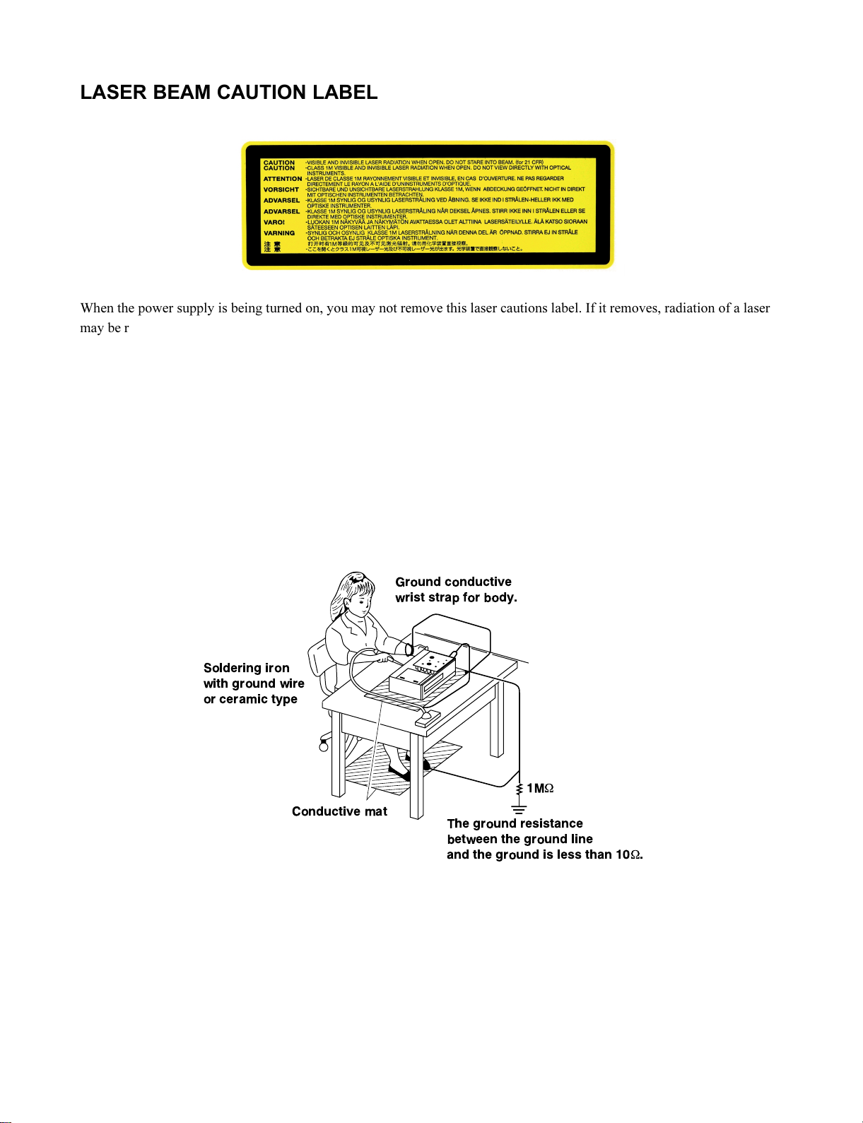
LASER BEAM CAUTION LABEL
When the power supply is being turned on, you may not remove this laser cautions label. If it removes, radiation of a laser
may be received.
PREPARATION OF SERVICING
Pickup Head consists of a laser diode that is very susceptible to external static electricity.
Although it operates properly after replacement, if it was subject to electrostatic discharge during replacement,
its life might be shortened. When replacing, use a conductive mat, soldering iron with ground wire, etc. to
protect the laser diode from damage by static electricity.
And also, the LSI and IC are same as above.
Ground conductive
wrist strap for body.
Soldering iron
with ground wire
or ceramic type
1M
W
Conductive mat
Manufactured under license from Dolby Laboratories. “Dolby” and the double-D symbol are trademarks of Dolby Laboratories.
·
“DTS” and “DTS Digital Out” are trademarks of Digital Theater Systems, Inc.
·
Manufactured under license from QSound Labs, Inc. U.S. patent Nos. 5,105,462, 5,208,860 and 5,440,638 and various foreign counterpart. Copyright
·
QSound Labs, Inc. 1998-2002. QXpanderTM is a trademark of QSound Labs, Inc. All rights reserved.
The ground resistance
between the ground line
and the ground is less than 10W.
Page 3
SAFETY NOTICE
SAFETY PRECAUTIONS
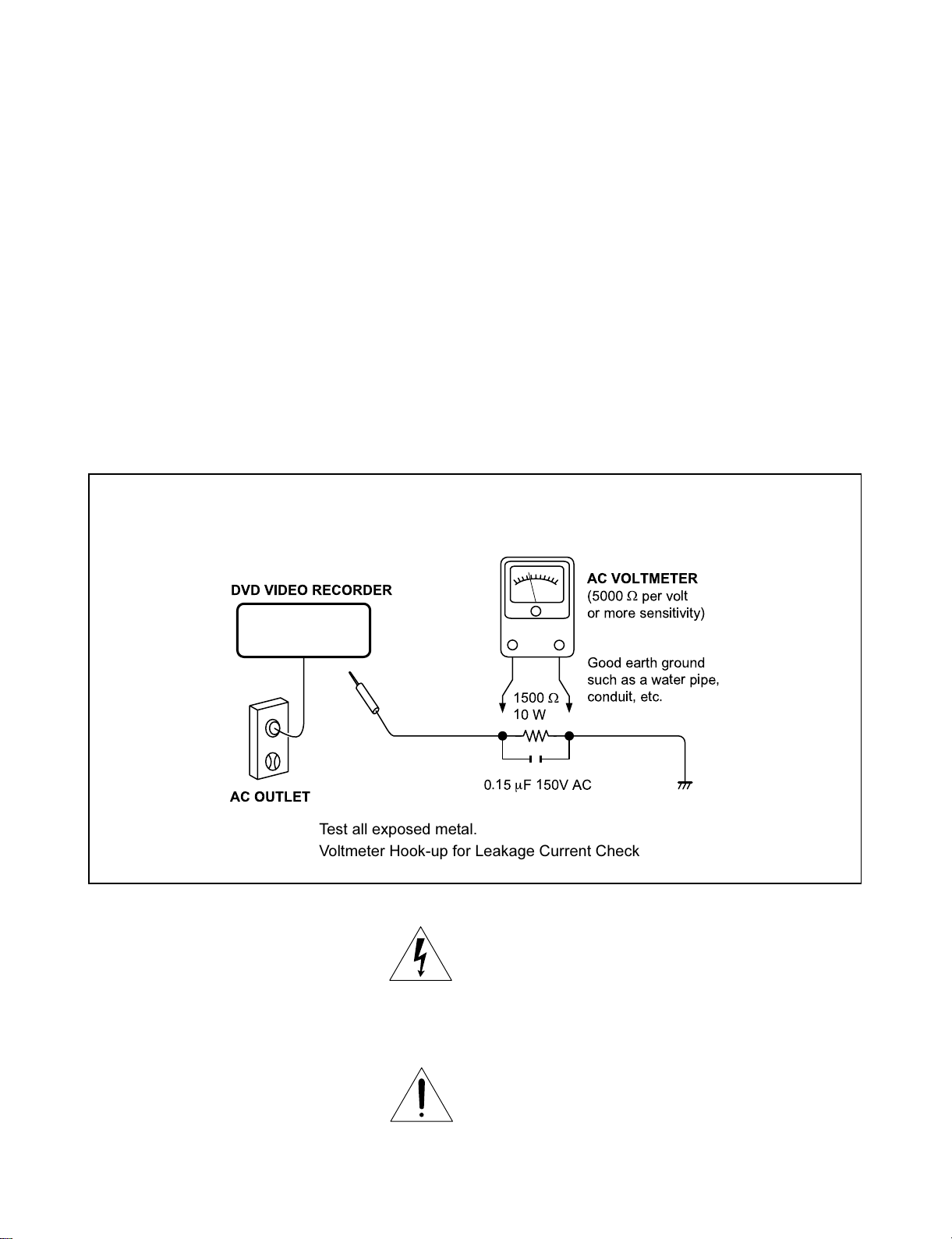
LEAKAGE CURRENT CHECK
Plug the AC line cord directly into a 120V AC outlet (do
not use an isolation transformer for this check). Use an
AC voltmeter, having 5000 W per volt or more sensitivity.
Connect a 1500 W 10 W resistor, paralleled by a 0.15 mF
150V AC capacitor between a known good earth ground
(water pipe, conduit, etc.) and all exposed metal parts of
cabinet (antennas, handle bracket, metal cabinet
screwheads, metal overlays, control shafts, etc.).
READING SHOULD NOT EXCEED 0.3V
Measure the AC voltage across the 1500 W resistor.
The test must be conducted with the AC switch on and
then repeated with the AC switch off. The AC voltage
indicated by the meter may not exceed 0.3 V. A reading
exceeding 0.3 V indicates that a dangerous potential
exists, the fault must be located and corrected.
Repeat the above test with the DVD VIDEO RECORDER
power plug reversed.
NEVER RETURN A DVD VIDEO RECORDER TO
THE CUSTOMER WITHOUT TAKING NECESSARY
CORRECTIVE ACTION.
DVD VIDEO RECORDER
AC OUTLET
Test all exposed metal.
Voltmeter Hook-up for Leakage Current Check
AC VOLTMETER
(5000Wper volt
or more sensitivity)
Good earth ground
such as a water pipe,
W
conduit, etc.
1500
10 W
0.15mF 150V AC
The lightning flash with arrowhead symbol, within an
equilateral triangle, is intended to alert the user to the
presence of uninsulated “dangerous voltage” within the
product’s enclosure that may be of sufficient magnitude to
constitute a risk of electric shock to persons.
The exclamation point within an equilateral triangle is
intended to alert the user to the presence of important
operating and maintenance (servicing) instructions in the
literature accompanying the appliance.
Page 4

1. OPERATING INSTRUCTIONS
CONTENTS
SECTION 1
GENERAL DESCRIPTIONS
2. LOCATION OF MAIN PARTS
2-1. Location of Main Parts
2-2. Location of PC Boards
PART REPLACEMENT AND ADJUSTMENT PROCEDURES
1. REPLACEMENT OF MECHANICAL PARTS
1-1. Cabinet Replacement
1-1-1. Top Cover
1-1-2. Front Panel
1-1-3. RAM Diver
1-1-4. Rear Panel
1-1-5. Fan
1. CIRCUIT SYMBOLS AND
SUPPLEMENTARY EXPLANATION
1-1. Precautions for Part Replacement
1-2. Solid Resistor Indication
1-3. Capacitance Indication
1-4. Inductor Indication
1-5. Waveform and Voltage Measurement
1-6. Others
2. PRINTED WIRING BOARD AND
SCHEMATIC DIAGRAM
3. BLOCK DIAGRAMS
3-1. Overall Block Diagram
4. CIRCUIT DIAGRAMS
4-1. Power Supply Circuit Diagram
4-2. Front Circuit Diagram
4-2-1. Front Jack Circuit Diagram
4-2-2. Front (LED) Circuit Diagram
4-2-2. Front (L) Circuit Diagram
4-2-3. Front (R) Circuit Diagram
SECTION 2
1-2. PC Board Replacement
1-2-1. Tuner Unit PC Board
1-2-2. Digital PC Board
1-2-3. Mother PC Board
1-2-4. Power PC Board
1-2-5. Front (R), Front (L), Front (LED), and
Front Jack PC Board
2. WIRING CONNECTION DIAGRAM
SECTION 3
SERVICING DIAGRAMS
4-3. Digital Circuit Diagram
4-3-1. Digital 1 Circuit Diagram
4-4. Mother Circuit Diagram
4-4-1. Tuner Circuit Diagram
4-4-2. Timer Circuit Diagram
4-4-3. Audio Circuit Diagram
4-4-4. Video Circuit Diagram
4-3. Tuner Unit Circuit Diagram
5. PC BOARDS
5-1. Front Jack PC Board
5-2. Front (LED) PC Board
5-3. Front (L) PC Board
5-4. Front (R) PC Board
5-5. Tuner Unit PC Board
5-6. Digital PC Board
5-7. Mother PC Board
SAFETY PRECAUTION
NOTICE
ABBREVIATIONS
SECTION 4
PARTS LIST
1. EXPLODED VIEWS
1-1. Packing Assembly
1-2. Chassis Assembly
2. PARTS LIST
Page 5

GENERAL DESCRIPTIONS
SECTION 1
GENERAL DESCRIPTIONS
1. OPERATING INSTRUCTIONS
Please refer to the owner's manual about the contents.
SECTION 1
Page 6
2. LOCATION OF MAIN PARTS
2-1. Location of Main Parts
RAM1 RAM DRIVE
ZG45 FAN
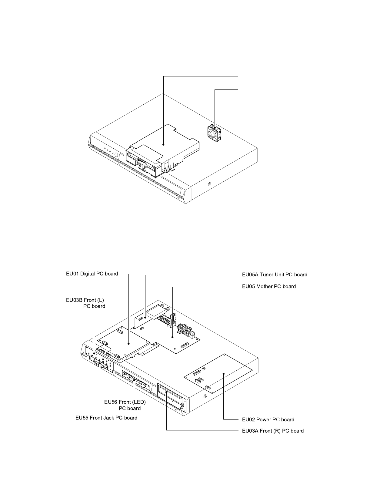
2-2. Location of PC Boards
EU01 Digital PC board
EU03B Front (L)
PC board
Fig. 1-2-1
EU05A Tuner Unit PC board
EU05 Mother PC board
EU56 Front (LED)
PC board
EU55 Front Jack PC board
EU02 Power PC board
EU03A Front (R) PC board
Fig. 1-2-2
Page 7
SECTION 2
PART REPLACEMENT AND
ADJUSTMENT PROCEDURES
CAUTIONS BEFORE STARTING PART REPLACEMENT
Electronic parts are susceptible to static electricity and may easily damaged, so do not forget to ground as required.
Many screws are used inside the unit. To prevent the screws from missing or dropping, etc. always use a magnetized
screwdriver in servicing. Several kinds of screws are used and some of them need special cautions. That is, take care of
the tapping screws securing molded parts and fine pitch screws used to secure metal parts. If they are used improperly,
the screw holes will be easily damaged and the parts can not be fixed.
1. REPLACEMENT OF MECHANICAL PARTS
ADJUSTMENT PROCEDURES
PART REPLACEMENT AND
1-1. Cabinet Replacement
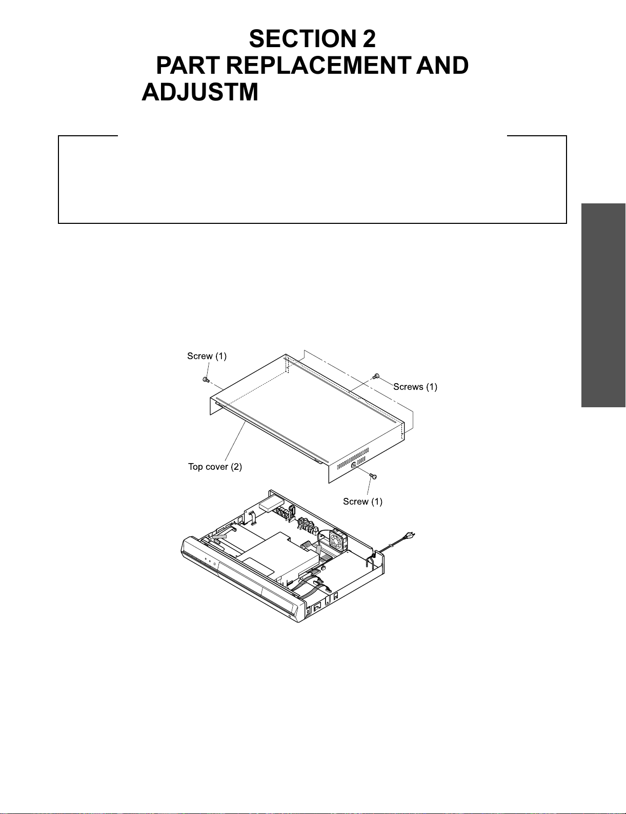
1-1-1. Top Cover
1. Remove five screws (1), then remove the top cover (2).
Screw (1)
Top cover (2)
SECTION 2
Screws (1)
Screw (1)
Fig. 2-1-1
Page 8

1-1-2. Front Panel
1. Remove the top cover. (Refer to item 1-1-1.)
2. Disconnect three connectors (1).
3. Remove one screw (2) and the earth lead.
4. Remove two screws (3) and four claws, then remove the front panel (4).
Connector (1)
Claw
Claws
Connector (1)
Screws (2)
Earth
Claw
Front panel (4)
Screws (3)
Fig. 2-1-2
1-1-3. RAM Drive
1. Remove the front panel. (Refer to item 1-1-2.)
2. Disconnect the flexible cable (1) and connector (2).
3. Remove three screws (3) and the screw (4), then remove the RAM drive (5).
4. Remove the shield cover (6).
Note:
• After replacing, attach the tape (1) to its original position.
Connector (1)
Screws (3)
Flexible
cable (1)
Screw (4)
Shield cover (6)
RAM drive (5)
Connector (2)
Fig. 2-1-3
Page 9

1-1-4. Rear Panel
1. Remove the top cover. (Refer to item 1-1-1.)
2. Remove the screw (1) and seven screws (2).
3. Remove the bush from the rear panel (3).
4. Remove two claws, then remove the rear panel (3).
5. Remove two screws (4), then remove the fan (5).
Rear panel (3)
Claw
Screw (1)
Screws (2)
Screws (4)
Bush
1-1-5. Fan
1. Remove the top cover. (Refer to item 1-1-1.)
2. Peel off the tape (1).
3. Disconnnect two connectors (2).
4. Remove two screws (3), then remove the fan (4).
Hexagonal
nuts
Tape (1)
Fig. 2-1-4
Fan (4)
Fan (5)
Screws (3)
Claw
Fig. 2-1-5
Connectors (2)
Page 10

1-2. PC Board Replacement
Screw (2)
Tuner Unit
PC board (4)
Screw (3)
Claw
Flexible
cable (1)
1-2-1. Tuner Unit PC Board
1. Remove the top cover. (Refer to item 1-1-1.)
2. Disconnect the flexible cable (1).
3. Remove the screw (2) and the screw (3).
4. Remove the claw, then remove the Tuner Unit PC board (4).
1-2-2. Digital PC Board
1. Remove the top cover. (Refer to item 1-1-1.)
2. Peel off the tape (1).
2. Disconnect the flexible cable (2).
3. Remove four screws (3), then remove the Digital PC board (4).
Fig. 2-1-6
Note:
• The Digital PC board (4) is connected to the Mother PC board (5) by three connectors (6). Take notice when removing.
Flexible
cable (2)
Connector
Tape (1)
Flexible
cable (2)
Screws (3)
Connector (6)
Digital PC
board (4)
Claw
Remove the connector claw
in the direction indicated
by the arrows to release the
flexible cable.
Connectors (6)
Mother PC board (5)
Fig. 2-1-7
Page 11

1-2-3. Mother PC Board
1. Remove the rear panel. (Refer to item 1-1-4.)
2. Remove the Tuner Unit PC board. (Refer to item 1-2-1.)
3. Remove the Digital PC board. (Refer to item 1-2-2.)
4. Disconnect three connectors (1).
5. Remove five screws (2) and the screw (3).
6. Pull out the Mother PC board (4) toward the rear side (indicated by the arrow).
Connectors (1)
Screws (2)
Fig. 2-1-8
Screw (3)
Connector (1)
Mother PC
board (4)
Page 12

1-2-4. Power PC Board
1. Remove the top cover. (Refer to item 1-1-1.)
2. Peel off the tape (1).
3. Disconnect four connectors (2).
4. Remove four screws (3), then remove the Power PC board (4).
Tape (1)
Connectors (2)
Connectors (2)
Power
PC board (4)
Connectors (2)
Screws (3)
Fig. 2-1-9
Page 13

1-2-5. Front (R), Front (L), Front (LED) and Front Jack PC Boards
1. Remove the front panel. (Refer to item 1-1-2.)
2. Peel off two tapes (1).
3. Remove four screws (2), then remove the stay (3).
4. Remove four screws (4) and two screws (5), then remove the Front (R) PC board (6) and Front (LED) PC board (7).
5. Remove two screws (8), then remove the Front Jack PC board (9).
6. Remove four screws (10), then remove the Front (L) PC board (11).
Note:
• After replacing, attach the tape (1) to its original position.
Front (L) PC board (11)
Front panel
Front Jack
PC board (9)
Tapes (1)
Screws (10)
Screws (5)
Front (LED)
PC Board (7)
Fig. 2-1-10
Screws (2)
Screws (8)
Stay (3)
Screws (4)
Front (R) PC board (6)
Note:
• Fasten with the tape, taking care so that the wire does not hang over the tray door.
Stay
Front (R) PC board
Front (LED)
PC board
Fasten with the tape.
Front (L) PC boardTray doorWire
Fig. 2-1-11
Front Jack
PC board
Page 14

2. WIRING CONNECTION DIAGRAM
After the servicing is complete, return the wiring to its original state by using the diagram below as a reference.
Tuner Unit
PC board
WB01
W051
W101
W104
Mother PC board
Digital PC board
RAM Drive
Fan
W801
Power PC board
W701
W102
Front panel
: Tape
: Flexible cable
Fig. 2-2-1
Page 15

SECTION 4
PARTS LIST
SAFETY PRECAUTION
The parts identified by ! ( ) mark are critical for safety. Replace only with part number specified.
The mounting position of replacement is to be identical with originals.
The substitute replacement parts which do not have the same safety characteristics as specified in the parts list may create
shock, fire or other hazards.
NOTICE
The part number must be used when ordering parts in order to assist in processing, be sure to include the model number
and description.
ABBREVIATIONS
Integrated Circuit (IC)
•
Capacitor (Cap)
•
• Capacitance Tolerance (for Nominal Capacitance more than 10pF)
Table 4-2-1
Symbol
Tolerance %B± 0.1C± 0.25D± 0.5
Symbol
Tolerance %
• Capa citan ce Tolerance (for Nominal Capacitance 10pF or less)
Symbol
Tolerance pFB± 0.1C± 0.25D± 0.5
Resistor (Res)
•
• Resistance tolerance
Symbol
Tolerance %B± 0.1C± 0.25D± 0.5
P
+ 100
0
Q
+ 30
– 10
T
+ 50
– 10
Ex. 10pF G = 10pF ± 2pF
F
± 1
U
+ 75
– 10
Table 4-2-2
F
± 1
Table 4-3-1
F
± 1
G
± 2
V
+ 20
– 10
G
± 2
G
± 2
J
± 5
W
+ 100
– 10
J
± 5
K
± 10
X
+ 40
– 20
Ex. 10µF J = 10µF ± 5%
K
± 10
M
± 20
Y
+ 150
– 10
M
± 20
N
± 30
Z
+ 80
– 20
PARTS LIST
SECTION 4
Ex. 470WJ = 470W± 5%
Page 16

1. EXPLODED VIEWS
1-1. Packing Assembly
ZF10
ZF11
ZF12
(D-R4SU/KR4SU)
ZF13
ZF01
ZF35
Fig. 4-4-1
Note: The shape of the packing
material is sometimes different.
Page 17

1-2. Chassis Assembly
EU01
EU05A
WB01
EU05
W051
ZG20
RAM1
ZG45
P801
EU02
EU03B
EU55
EU56
EU03A
ZG01
Fig. 4-4-2
Page 18

2. PARTS LIST
Location
No.
P801 P000416780 Cord,Power UL
!
RAM1 P000438600 DVD-RAM DAV-WR412(RAM-R650)
!
W051 P000433820 Cable,Flexible FFC,40P,L280
WB01 P000439330 Cable,Flexible FFC,11P,L90
ZF01 P000438630 Remote Control Unit SE-R0176
ZF10 P000416410 Owners Manual,OP English,D-R4SU/SC/KR4SU
!
ZF11 P000416400 Owners Manual,ST English,D-R4SU/SC/KR4SU
!
ZF12 P000416430 Owners Manual,Quick Spanish,D-R4SU/KR4SU
!
ZF13 P000416420 Owners Manual,Quick English,D-R4SU/SC/KR4SU
!
ZF10 P000416450 Owners Manual,OP French,D-R4SC
!
ZF11 P000416440 Owners Manual,ST French,D-R4SC
!
ZF35 P000416800 IR Blaster RWS1000-0062E
ZG01 P000438710 Panel Assy,Front D-R4SU/R4SC
ZG01 P000440030 Panel Assy,Front D-KR4SU
ZG20 P000438610 Cover,Top
ZG45 P000401260 Fan,DC 5025LL12SND2
Part No. Description
- MECHANICAL PARTS -
Page 19

Location
No.
EU01 P000439050 PC Board Assy Digital,D-R4SU/KR4SU
EU01 P000439340 PC Board Assy Digital,D-R4SC
IC202 P000378050 IC SN74AHC1G04HDCKR
IC203 P000378050 IC SN74AHC1G04HDCKR
IC302 P000416750 IC BA25BC0FP
IC303 P000440410 IC MM1573DNRE
IC304 P000391240 IC NJM2125F
IC306 P000378040 IC SN74AHC1G08HDCKR
IC307 79040306 IC PST594JMT
IC315 P000377920 IC SN74LV244APWR
Q301 79050018 Transistor,Chip 2SA1162-Y
Q302 79050018 Transistor,Chip 2SA1162-Y
Q303 79050018 Transistor,Chip 2SA1162-Y
Q304 79050018 Transistor,Chip 2SA1162-Y
Q305 79050018 Transistor,Chip 2SA1162-Y
Q306 79050016 Transistor,Chip 2SC2712-Y
Q307 79050016 Transistor,Chip 2SC2712-Y
Q308 79050018 Transistor,Chip 2SA1162-Y
Q309 79050018 Transistor,Chip 2SA1162-Y
X201 P000440380 Oscillator,Crystal
X302 79089168 Oscillator,Crystal
X303 P000377990 Oscillator,Crystal 27.0M
Part No. Description
- ELECTRICAL PARTS -
- INTEGRATED CIRCUITS -
- TRANSISTORS -
- MISCELLANEOUS -
EU02 P000438620 PC Board Assy Power
!
EU03A P000438660 PC Board Assy Front(R)
- INTEGRATED CIRCUITS -
IC101 P000416700 IC PT6315
- DIODES -
D101 79060019 Diode,Chip 1SS355
- MISCELLANEOUS DS101 P000440490 Display,FL VFD20-0812FN
MT101 P000440420 Module,IR GP1UM261XK0F
S107 P000377940 Switch,Push-Lever
EU03B P000438670 PC Board Assy Front(L)
- MISCELLANEOUS S101 P000391050 Switch,Tact
S102 P000391050 Switch,Tact
S103 P000391050 Switch,Tact
S104 P000391050 Switch,Tact
S105 P000391050 Switch,Tact
S106 P000391050 Switch,Tact
S108 P000391050 Switch,Tact
S109 P000391050 Switch,Tact
S110 P000391050 Switch,Tact
S112 P000391050 Switch,Tact
EU05 P000438650 PC Board Assy Mother
- INTEGRATED CIRCUITS IC701 P000391180 IC PST3222NR
IC702 P000391150 IC DC74HCT125M
IC901 P000440480 IC PCM1755DBQR
IC902 P000440510 IC RC4580IDR
IC903 P000416650 IC,Terminal,OPT LAF1001-0301F
IC906 79040397 IC MM1575ANRE
Page 20

Location
No.
ICB10 P000440500 IC XC6209F502PR
ICW01 P000391260 IC MM1568DJBEG
ICX03 79040382 IC MM1140XFFE
ICX04 79040369 IC MM1113XFBE
ICX05 P000440500 IC XC6209F502PR
ICX31 79040371 IC BA7046F
ICX32 P000363370 IC NJM2330MV
Q901 79050014 Transistor,Chip HN1C03F
Q902 79050014 Transistor,Chip HN1C03F
Q904 79050001 Transistor,Chip RN2402
Q905 79050100 Transistor,Chip RN1402
Q906 79050001 Transistor,Chip RN2402
Q907 79050100 Transistor,Chip RN1402
Q908 79050100 Transistor,Chip RN1402
QB08 79050016 Transistor,Chip 2SC2712-Y
QW02 79050100 Transistor,Chip RN1402
QW03 79050018 Transistor,Chip 2SA1162-Y
QW04 79050018 Transistor,Chip 2SA1162-Y
QX06 79050018 Transistor,Chip 2SA1162-Y
QX09 79050018 Transistor,Chip 2SA1162-Y
QX31 79050016 Transistor,Chip 2SC2712-Y
QX32 79050100 Transistor,Chip RN1402
QX33 P000440390 Transistor,Chip RN1404
D702 79060028 Diode,Chip 1SS226
D901 79060019 Diode,Chip 1SS355
D902 79060019 Diode,Chip 1SS355
J901 P000440440 Jack,RCA MSD-244V-09
JW01 P000440450 Jack,RCA MSP-801V1-02-01-B
JW02 P000440460 Jack,RCA MSD-243V-18
JX01 P000440470 Jack,RCA MSP-830V-07
X700 P000391040 Oscillator,Crystal 12.5MHz
X701 P000363400 Oscillator,Crystal 32.768kHz
Part No. Description
- TRANSISTORS -
- DIODES -
- MISCELLANEOUS -
EU05A P000438680 PC Board Assy Tuner
- MISCELLANEOUS MB01 P000440520 Tuner 115-V-JA45AT
!
EU55 P000438690 PC Board Assy Front Jack
- MISCELLANEOUS J170 P000387300 Jack,DV
J171 P000402780 Jack,3P+1Y/C
EU56 P000438700 PC Board Assy Front(LED)
- DIODES D110 P000440400 Diode,LED SLR343BBT3F
D111 P000440400 Diode,LED SLR343BBT3F
Page 21

SPECIFICATIONS
Power requirement during operation
Power requirement at standby
Power supply
Mass
External dimension
Incoming channels
Antenna input/output terminal
Signal system
Laser
Format
Image recording system
Sound recording system
VIDEO input
VIDEO output
S-VIDEO input
S-VIDEO output
COMPONENT output(Y, PB, PR)
AUDIO input
AUDIO output
DIGITAL AUDIO OUTPUT BITSTREAM/PCM
(OPTICAL terminal)
Remote control
Operating conditions
Clock display
Clock accuracy
• The design and specifications may change without prior notice.
• The Illustrations and screens described in this manual may be exaggerated or simplified for easy recognition and may be slightly different from the actual unit.
21W
2.7W
120V AC, 60 Hz
3.5kg
Width 430 x Height 58 x Depth 304mm
TV : 2-69CH, Cable : 1-125CH
VHF/UHF : 75W, F Connector
Standard NTSC Color TV system
Semiconductor laser, Wavelength : 650nm/780nm
DVD -VR format
DVD-Video format
MPEG2
Dolby Digital M1
1.0Vp-p (75W), Sync signal negative, Pin jack x 2 systems, 1 at rear, 1 in front
1.0Vp-p (75W), Sync signal negative, Pin jack x 1 system, 1 at rear
(Y) 1.0Vp-p (75W), Sync signal negative,
(C) 0.286Vp-p (75W) 1 at rear, 1 in front
Mini DIN4 Pin x 2 systems
(Y) 1.0Vp-p (75W), Sync signal negative,
(C) 0.286Vp-p (75W) 1 at rear
Mini DIN4 Pin x 1 system
Y output (green), 1.0Vp-p (75W), Sync signal negative, Pin jack x 1 system
PB, PR output (blue, red), 0.7Vp-p (75W), Pin jack x 1 system each
2.0V (rms), 22kW or above, pin jack (L, R) x 2 systems
1 at rear, 1 in front
2.0V (rms), 2.2kW or below, pin jack (L, R) x 1 system
1 at rear
Optical connector x 1 system
Wireless remote control (SE-R0176)
Temperature: 41°F~95°F (5°C~35°C)
Position: Horizontal
12 hour digital display
Quartz (monthly deviation: approximately ±30 seconds)
Page 22

TOSHIBA CORPORATION
1-1, SHIBAURA 1-CHOME, MINATO-KU, TOKYO 105-8001, JAPAN
 Loading...