

Page 1

PLAIN PAPER FA CSIMILE
/
OPERATOR’S MANU AL
Page 2

EPA ENERGY STAR
The United States Environmental Protection Agency (EP A) has introduced a voluntary program, the ENERGY
®
ST AR Program, to encourage the widespread and voluntary use of energy-efficient technologies that enhance the
workplace, improve product performance, prevent pollution, and reduce your energy costs. As an ENERGY
ST AR Partner , Toshiba has determined that this facsimile model meets the ENERGY ST AR guidelines for energy
efficiency . ENERGY ST AR guidelines require that all ENERGY ST AR facsimiles maintain very low power
consumption during idle state or have a "Power Saver" feature that will automatically stand-down to an idle state
after a period of inactivity .
For more information on the ENERGY ST AR Program, please contact:
ENERGY ST AR Printers/Fax Machines
US EP A (6202J)
W ashington, DC 20460
ENERGY STAR is a U.S. registered mark.
Page 3

NOTICE T O USERS
Read through this manual before using the machine. Keep the manual in a convenient location so that you may refer to the manual whenever necessary.
U. S. A.
WARNING FCC Notice: Part 15
This terminal has been tested and found to comply with the limits for a Class B
digital device, pursuant to Part 15 of the FCC Rules. These limits are designed to
provide reasonable protection against harmful interference in a residential installation. This equipment generates, uses, and can radiate radio frequency energy and,
if not installed and used in accordance with this guide, may cause harmful interference to radio communications. However, there is no guarantee that interference will
not occur in a particular installation. If this equipment does cause harmful interference to radio or television reception, which can be determined by turning the
equipment off and on, the user is encouraged to try to correct the interference by
one or more of the following measures:
- Reorient or relocate the receiving antenna.
- Increase the separation between the equipment and receiver.
- Connect the equipment into an outlet on a circuit different from that to
which the receiver is connected.
- Consult the dealer or an experienced radio/TV technician for help.
WARNING FCC Notice: Part 68
This equipment complies with Part 68 of the FCC Rules. On the rear of this
equipment is a label that contains, among other information, the FCC Registration
Number and ringer equivalence number (REN) for this equipment. If requested, this
information must be provided to the telephone company.
The REN is used to determine the quantity of devices that may be connected to the
telephone line. Excessive REN’s on the telephone line may result in the devices not
ringing in response to an incoming call. In most, but not all areas, the sum of the
REN’s should not exceed five (5.0). To be certain of the number of devices that
may be connected to the line, as determined by the total REN’s contact the
telephone company to determine the maximum REN for the calling area.
If you experience trouble with this facsimile machine, please contact
TOSHIBA AMERICA BUSINESS SOLUTIONS, INC.
Electronic Imaging Division
2 Musick, Irvine, CA 92618-1631
for repair/warranty information. If the trouble is causing harm to the telephone
network, the telephone company may request you remove the equipment from the
network, until the problem is resolved.
The equipment may not used on coin service provided by the telephone network,
connection to Party Line Service is subject to state tariffs. (Contact the state public
utility commission, or corporation commission for information.)
This device is equipped with a USOC RJ11C connector.
THE TELEPHONE CONSUMER PROTECTION ACT: The Telephone Consumer
Protection Act of 1991 makes it unlawful for any person to use a computer or other
electronic device to send any message via a telephone fax machine unless such a
message clearly contains in a margin at the top or bottom of each transmitted page
or on the first page of the transmission, the date and time it is sent and an
identification of the business or other entity, or other individual sending the message and the telephone number of the sending machine or such business, other
entity, or individual.
In order to program this information into your fax machine, you should complete the
setup procedures listed for station ID number and name on pages 42 and 43 in this
manual.
This equipment is hearing aid compatible.
If your facsimile machine causes harm to the telephone network, the telephone
company will notify you in advance that temporary discontinuance of service may
be required. But if advance notice is not practical, you will be notified as soon as
possible, also, you will be advised of your right to file a complaint with the FCC if
you believe it is necessary.
The telephone company may make changes in its facilities, equipment, operations,
or procedures that could affect the operation of the equipment. If this happens, the
telephone company will provide advance notice in order for you to make the necessary modifications in order to maintain uninterrupted service.
1
Page 4

Canada
NOTICE: The Industry Canada label identifies certified equipment. This certi-
fication means that the equipment meets telecommunications network protective,
operational and safety requirements as prescribed in the appropriate Terminal
Equipment Technical Requirements document(s). The Department does not guarantee the equipment will operate to the user’s satisfaction.
Before installing this equipment, users should ensure that it is permissible to
connect a facsimile to the facilities of their local telecommunications company.
The equipment must also be installed using an acceptable method of connection.
The customer should be aware that compliance with the above conditions may not
prevent degradation of service in some situations.
Repairs to certified equipment should be coordinated by a representative designated
by the supplier. Any repairs or alterations made by the user to this equipment, or
equipment malfunctions, may give the telecommunications company cause to request the user to disconnect the equipment.
Users should ensure for their own protection that the electrical ground connections
of the power utility, telephone lines and internal metallic water pipe system, if
present, are connected together. This precaution may be particularly important in
rural areas.
CAUTION: Users should not attempt to make such connections themselves,
but should contact the appropriate electric inspection authority, or electrician, as
appropriate.
The Ringer Equivalence Number of your facsimile is 0.3
AVIS: L’étiquette d’lndustrie Canada identifie le marériel homologué. Cette
étiquette certifie que le matériel est conforme aux normes de protection,
d’exploitation et de sécurité des réseaux de télécommunications, comme le
prescrivent les documents concernant les exigences techniques relatives au
matériel terminal. Le Ministére n’assure toutefois pas que le matériel fonctionnera à
la satisfaction de l’utilisateur.
Avant d’installer ce matériel, l’utilisateur doit s’assurer qu’il est permis de le
raccorder aux installations de l’entreprise locale de télécommunication. Le matériel
doit également être installé en suivant une méthode acceptée de raccordement.
L’abonné ne doit pas oublier qu’il est possible que la conformité aux conditions
énoncées ci-dessus n’empêche pas la dégradation du service dans certaines situations.
Les réparations de matériel homologué doivent être coordonnées par un
représentant désigné par le fournisseur. L’entreprise de télécommunications peut
demander à l’utilisateur de débrancher un appareil à la suite de réparations ou de
modifications effectuées par l’utilisateur ou à cause de mauvais fonctionnement.
Pour sa propre protection, l’utilisateur doit s’assurer que tous les fils de mise à la
terre de la source d’énergie électrique, des lignes téléphoniques et des
canalisations d’eau métalliques, s’il y en a, sont raccordés ensemble. Cette
précaution est particulièrement importante dans les régions rerales.
Avertissement: L’utilisateur ne doit pas tenter de faire ces raccordements
luimême; il doit avoir recours à un service d’inspection des installations électriques,
ou à un électricien, selon le cas.
NOTICE: The Ringer Equivalence Number (REN) assigned to each terminal
device provides an indication of the maximum number of terminals allowed to be
connected to a telephone interface. The termination on an interface may consist of
any combination of devices subject only to the requirement that the sum of the
Ringer Equivalence Numbers of all the devices does not exceed 5.
TOSHIBA OF CANADA LIMITED
Office Product Group
191 McNABB STREET
MARKHAM, ONTARIO L3R 8H2
2
L’indice d’equivalence de la sonnerie de ce matériel 0.3
AVIS: L’indice d’équivalence de la sonnerie (IES) assigné à chaque dispositif
terminal indique le nombre maximal de terminaux qui peuvent être raccordés à une
interface. La terminaison d’une interface téléphonique peut consister en une
combinaison de quelques dispositifs, à la seule condition que la somme d’indices
d’équivalence de la sonnerie de tous les dispositifs n’excède pas 5.
Page 5
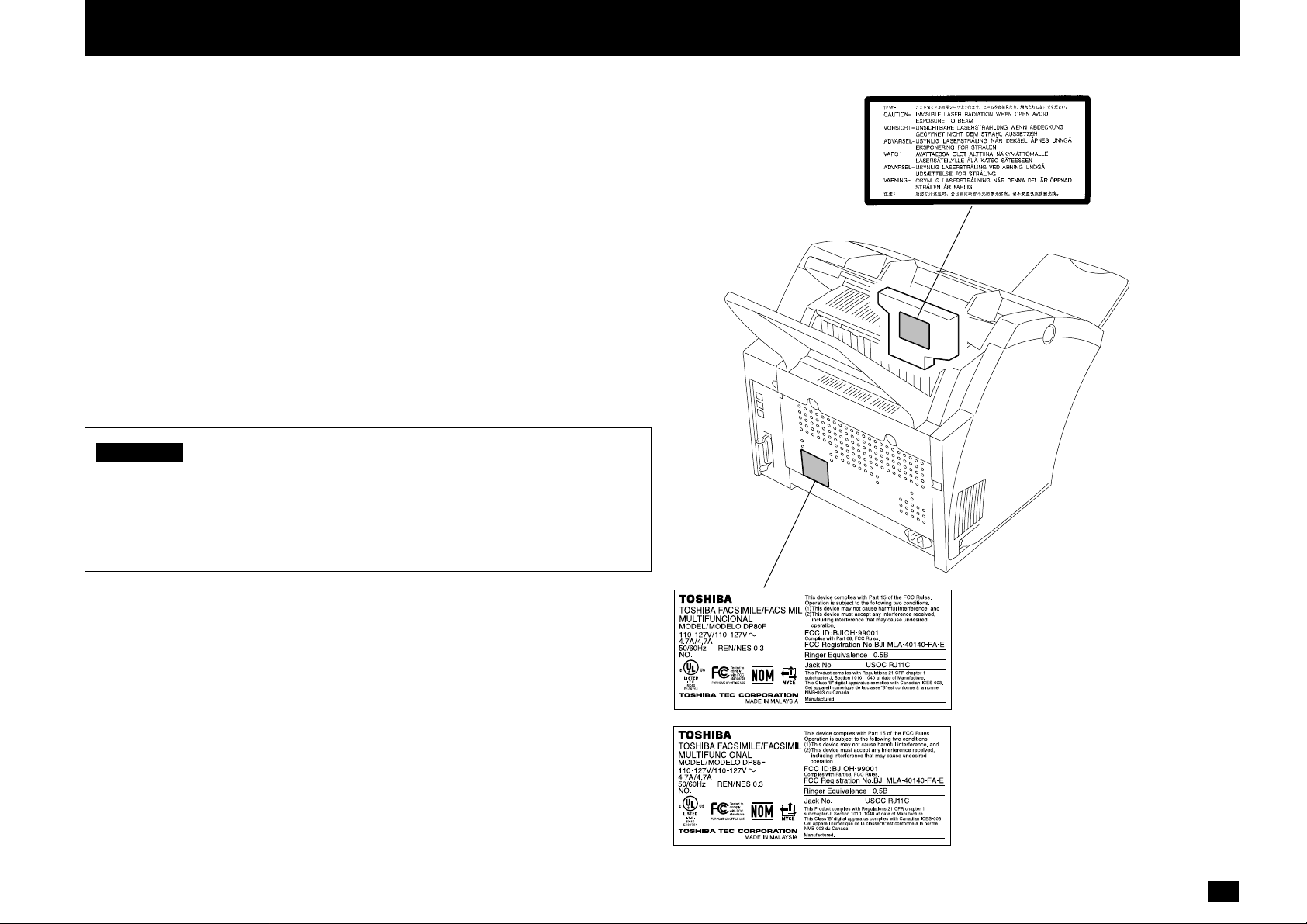
LASER SAFETY INFORMATION
This facsimile is certified as a Class I laser product under the U.S. Department of
Health and Human Services (DHHS) Radiation Performance Standard according to
the Radiation Control for Health and Safety Act of 1968. This means that this
facsimile does not produce hazardous laser radiation.
All laser light emitted inside the facsimile is completely confined within protective
housings when any part of the facsimile is opened. This means that the facsimile is
safe to use during normal operation and maintenance. Adjustment or performance
of procedures other than those specified herein may result in hazardous laser
exposure.
The Center for Devices and Radiological Health (CDRH) of the U.S. Food and Drug
Administration implemented regulations for laser products. These regulations apply to
laser products manufactured from August 1, 1976. Compliance is mandatory for
products marketed in the United States. The sample label shown below indicates
compliance with these CDRH regulations and is attached to all laser facsimiles marketed in the United States.
WARNING Use of controls, adjustments or performance of procedures other
than those specified in this manual may result in hazardous radiation exposure.
Only trained and qualified personnel may open covers or remove
parts that are not explicitly shown and described in the Operator’s
Manual as being accessible to the Operator.
01
3
Page 6

CONTENTS
NOTICE T O USERS................................................................1
LASER SAFETY INFORMATION...........................................3
FEATURES .............................................................................8
CARE AND MAINTENANCE..................................................9
INTRODUCTION.......................................................... 10
FACSIMILE UNIT DESCRIPTIONS........................................10
Front Vie w..............................................................................................10
Rear View..............................................................................................11
OPERATION PANEL .............................................................. 13
SETUP ......................................................................... 16
UNPACKING...........................................................................16
Unpack the Carton ................................................................................16
Make Sure All Items are Enclosed.........................................................16
Select a Desirable Location ...................................................................17
F A CSIMILE MA CHINE INSTALLATION .................................18
Connecting Y our TOSHIBA Facsimile.....................................................18
Recording Paper Exit Tr ay .....................................................................19
Document Support ................................................................................19
Document Exit Tra y................................................................................19
Recording Paper Tra y ............................................................................19
Bypass T ra y ...........................................................................................19
INITIAL PRINTING SUPPLIES INSTALLATION ....................20
Recording Paper Installation (Recording P aper Tra y).............................20
Recording Paper Installation (Bypass Tra y) ...........................................23
Recording Paper Installation (Optional Recording P aper Tra y)...............24
Drum Unit and Toner Cartridge Installation ............................................27
PRINTING SUPPLIES REPLACEMENT................................29
T oner Cartridge Replacement................................................................29
Drum Unit Replacement ........................................................................31
QUICK START ........................................................................34
T e rminal ID ............................................................................................34
Transmitting ...........................................................................................34
Receiving ..............................................................................................34
USER INTERFACE OPERATION ...........................................35
Menu Operation.....................................................................................35
Character Entry .....................................................................................36
INITIAL SETUP ......................................................................38
Initial Setting Summary..........................................................................38
Language Selection...............................................................................39
Date and Time Setting...........................................................................40
Terminal ID Setting ................................................................................42
Dial T ype Setting....................................................................................44
DEVICE CONFIGURATION....................................................45
Configuration Summary.........................................................................45
Ringer V olume Adjustment ....................................................................46
Alarm T one V olume Adjustment .............................................................47
Key Touch T one V olume Adjustment.......................................................48
Monitor V olume Adjustment ...................................................................49
Po wer Sav er Operation..........................................................................50
Department Code Setting ......................................................................52
Department Code Maintenance.............................................................54
Account Codes Setting ..........................................................................56
Line Monitor Default Setting...................................................................57
Receive Interval Setting Operation ........................................................58
ECM Default Setting ..............................................................................59
Sort Copy Setting ..................................................................................60
Setting Redial (Interval and Counter).....................................................61
Reception Mode Default Setting ............................................................62
Copy Reduction Setting.........................................................................64
BASIC FUNCTIONS .................................................... 65
AUTOMA TIC TELEPHONE DIALING .....................................65
Abbreviated Dialer Registration .............................................................65
One Touch Dialer Registration ...............................................................71
Group Number Registration...................................................................77
TRANSMIT CONFIGURATION...............................................81
Document Specifications .......................................................................81
Document Loading ................................................................................82
Scan Resolution Setting ........................................................................83
Contrast Setting.....................................................................................84
4
Page 7

Default Setting f or Document Mode (Resolution and Contrast)..............85
COPYING ...............................................................................86
Paper Siz e for Cop ying..........................................................................86
Copying Procedure................................................................................87
DIALING METHODS ..............................................................89
One T ouch Key Dialing...........................................................................89
Abbreviated Dialing................................................................................90
Alphabet Dialing ....................................................................................91
Ke ypad Dialing ......................................................................................92
TRANSMITTING .....................................................................93
Memory T ransmission............................................................................93
Memory T ransmission Procedure .....................................................94
Direct T ransmission ...............................................................................95
Direct Transmission as Def ault Setting..............................................95
Temporary Direct Transmission.........................................................97
On-hook Transmission (Monitor Speak er Dialing).............................98
Off-hook Transmission (Optional Handset Dialing) ...........................99
External Off-hook Transmission
(Transmission Using an External Telephone)....................................101
Redialing ...............................................................................................102
Automatic Redialing..........................................................................102
Manual Redialing Direct Transmission..............................................102
Manual Redialing Jobs in Memory....................................................103
RECEIVING ............................................................................104
Automatic Reception Mode....................................................................104
F AX/TAD Switching Mode......................................................................104
TEL/F AX A uto Switching Mode..............................................................105
Manual Receiving Mode ........................................................................105
Selecting the Reception Mode...............................................................106
Recording Paper Size............................................................................106
TELEPHONE HANDSET OPERATION (Optional) ................107
On-hook Dialing.....................................................................................107
Tone Output...........................................................................................108
Redialing ...............................................................................................108
COMMUNICA TION STATUS...................................................109
Current Job Status ................................................................................109
Communication Journal.........................................................................109
CANCELLING A COMMUNICATION JOB.............................110
Cancelling a Direct Tr ansmission...........................................................110
Cancelling a Job Reservation ................................................................110
ADVANCED FUNCTIONS ........................................... 112
MUL TI-ADDRESS TRANSMISSION (BROADCASTING) ......112
Group Broadcast Transmission..............................................................112
Multi-Key Quick Broadcast Transmission ...............................................113
RELA Y TRANSMISSION ........................................................115
Relay T r ansmission, Rela y-Relay T ransmission Overview .....................115
Relay Transmission Originating Procedure ............................................116
POLLING & MAILBOX COMMUNICATIONS.........................118
Polling & Mailbo x Ov erview....................................................................118
Polling Reservation...........................................................................118
Polling Reception..............................................................................118
Open Mailbox (ITU-T Compatible)....................................................119
Simple & Security Polling Reservation...................................................120
Multi Mailbox P olling Reservation ..........................................................122
Simple & Secure Polling ........................................................................124
Multi-Address Polling.............................................................................126
T urnaround P olling.................................................................................128
Continuous Polling.................................................................................130
MAILBOX (ITU-T Compatib le)...............................................132
Setting Up a Mailbox..............................................................................132
Deleting a Mailbox .................................................................................134
Sending a Document to a Mailbox (Remote Hub)..................................136
Reserving a Document to a Mailbox (Local Hub)...................................138
Retrieving (P olling) a Document from a Mailbox (Remote Hub).............140
Printing a Document from a Mailbox (Local Hub) ..................................142
Cancelling Documents in a Mailbox (Local Hub)....................................144
ADV ANCED TRANSMISSION FUNCTIONS ..........................146
Department Code Access .....................................................................146
Account Code Entry ..............................................................................147
Chain Dialing .........................................................................................148
Default Setting f or Memory Transmission...............................................149
Default Setting f or Security Transmission...............................................150
Cover Sheet Registr ation.......................................................................151
5
TION
INTRODUC-
SETUP
BASIC
FUNCTIONS
ADVANCED
FUNCTIONS
REPORTS
LISTS AND
TROUBLE-
SHOOTING
MODE
USER TEST
Page 8

Setting Recovery Tr ansmission..............................................................152
TTI (Transmit Terminal ID) Print .............................................................153
Send after Scan Default Setting.............................................................155
Document Length Setting ......................................................................156
PIN Mask...............................................................................................157
ADVANCED RECEPTION FUNCTIONS ................................158
Secure Reception Access Code Setting ................................................158
Secure RX Activation P eriod Setting......................................................160
Memory Reception Setting ....................................................................162
Reception-Reduction Setting .................................................................163
Reception-Discard Setting.....................................................................164
Reverse Order Printing Setting..............................................................165
Privileged Reception..............................................................................166
RTI (Remote Terminal ID) Print..............................................................167
Setting Separator Page .........................................................................168
Secure RX Temporary Stop ...................................................................169
ADVANCED PC FUNCTION...................................................170
Letter Head Paper Setting .....................................................................170
TRANSMISSION OPTIONS ...................................................171
Security T ransmission............................................................................171
Disabling ECM Temporarily....................................................................172
Dialing with Sub-Address ......................................................................173
Enabling or Disabling Send after Scan Temporarily ...............................175
Attaching or Printing a Cover Sheet.......................................................177
Delayed Comm unication (Time Designation).........................................179
Priority T ransmission .............................................................................180
Sending Recovery Transmission............................................................181
Low Speed Transmission .......................................................................183
Line Monitor...........................................................................................184
Setting the Page Count..........................................................................185
Communication Report Print .................................................................186
LISTS AND REPORTS................................................ 187
LIST AND REPORT OPTIONS SETTING..............................187
Reception Journal Settings....................................................................187
Direct T ransmission Report Setting........................................................189
Memory T ransmission Report Setting ....................................................190
Multi-Address Report Setting.................................................................191
Multi-Polling Report Setting ...................................................................192
Relay Originator Report Setting.............................................................193
Reception List Settings..........................................................................194
LIST AND REPORT PRINT FORMAT AND
PRINTING PROCEDURE ....................................................... 195
T r ansmission/Reception Journal (Communication Journal) ...................195
T r ansmission Report..............................................................................196
Memory T ransmission Report ................................................................197
Reservation List.....................................................................................198
Multi-Address T ransmission Report .......................................................199
Multi-Polling Report ...............................................................................200
Relay Send Originator Report ...............................................................201
Mailbox (ITU-T Compatible F-code Comm unication) List.......................202
Department Control List ........................................................................203
Preset Dialing Number Lists ..................................................................204
All of Lists.........................................................................................204
Abbreviated Dial Number List ...........................................................205
One Touch Number List ....................................................................206
Group Number List ...........................................................................207
Address Book List ............................................................................208
Function List.....................................................................................209
Menu List..........................................................................................210
Po wer F ailure List ..................................................................................211
TROUBLESHOOTING ................................................. 212
Error Messages .....................................................................................212
Paper J am Error Codes.........................................................................214
Error Codes Printed on Reports ............................................................215
T ransmission Prob lems..........................................................................216
Reception Problems ..............................................................................217
Clearing a Document Jam .....................................................................218
Clearing a Recording Paper Jam...........................................................219
When the Recorded Image is not Clear... ..............................................224
Document Scanner Cleaning Procedure ..........................................224
Recording Unit Cleaning Procedure .................................................226
USER TEST MODE...................................................... 228
AUT OMATIC TEST MODE ......................................................228
AUT O TEST...........................................................................................228
6
Page 9

INDIVIDUAL TEST MODE ...................................................... 229
INDIVIDUAL TEST Summary ................................................................229
ADF TEST .............................................................................................230
KEY TEST .............................................................................................232
LED TEST .............................................................................................233
LCD TEST .............................................................................................234
SPEAKER TEST ...................................................................................235
SENSOR TEST .....................................................................................236
PRINT TEST..........................................................................................238
TEST RESULT ........................................................................239
PRINTING a TEST RESULT..................................................................239
REMOTE SERVICE ..................................................... 240
RDC (Remote Diagnosis Configuration) Service ............... 240
AU TOMA TIC SUPPLIES ORDER........................................... 241
Automatic Supplies Order Setting..........................................................241
SPECIFICATIONS ....................................................... 242
SUPPLIES ................................................................... 243
HARDWARE OPTIONS ............................................... 243
TOSHIB A VIEWER....................................................... 245
INDEX .......................................................................... 275
7
Page 10

FEATURES
Super G3 High-speed Communications (DP85F only)
Provides state-of-the-art V.34 modem technology for worldwide compatibility at
speeds up to 33,600 bits per second.
High Resolution, 128 Level Halftone
With a maximum resolution of 16 dots/mm x 15.4 lines/mm (406 DPI x 391 LPI)
and 128 level halftone, precision drawings, small-size characters, photographs,
etc. are copied, sent, and received with exceptional clarity.
Open Network Mailbox Systems
Your new Toshiba provides ITU-T F-code communication for Open Mailbox operation.
Rapid Scan Document Scanning
Allows letter sized originals to be scanned into memory in as little as 3 seconds
per page.
38 Programmable One Touch Autodialer Keys
Allows remote locations to be quickly dialed at the touch of a key saving time and
eliminating mis-dialed phone numbers.
100/150 Abbreviated Autodial Locations
In addition to the 38 One Touch Autodialer Keys, 100 (DP80F)/150 (DP85F) abbreviated locations can also be programmed with other frequently called locations.
These locations can then be easily accessed using abbreviated codes ranging
from 001 to 999.
Substitute Memory Reception
When the recording paper or supplies have been depleted or in the event of a
recording paper jam, your receptions will be safely stored in memory until the
problem is corrected.
Memory Release
Minimizes the potential for memory overflows when connected with a remote location. After each page has been successfully transmitted it is released from memory
to make room for subsequent pages.
TOSHIBA Viewer
Installing the TOSHIBA Viewer software that comes with the machine enables
following functions (see page 244).
• 600 dpi plain paper laser printer
PC print jobs are printed on plain paper at a crisp 600 dpi print resolution.
• Setting and programming the machine from a PC
You can set up and program the machine from a PC.
• PC Scanner function
The machine can be used as a Twain compatible B/W image scanner (16 dots/
mm x 15.4 dots/mm max.).
User Test Mode
The user test mode can help you to find the cause of a machine problem should a
failure occur.
5 Function Keys
Five frequently used functions are assigned to the keys located on the right side of
One Touch Index Panel. These keys allow direct access to frequently used function settings and operations.
Multi-address (Broadcast Transmission)
This feature allows the transmission of a document to multiple remote units with
one operation sequence. Locations may be selected using the autodialer or infrequently dialed locations that have not been preregistered.
Multi-Memory Access Operation
Allows up to 4 operations such as transmission or reception, printing, scanning,
and programming to be performed at the same time.
Super Power Saver Mode
Reduces power consumption to approx. 2W by turning all unnecessary functions
off in the standby mode.
8
Auto Supply Order Function
This function allows the machine to order supplies (Drum Kit and Toner Kit) automatically.
Page 11

CARE AND MAINTENANCE
About Power for the Unit
• This unit requires 120 V AC, 60Hz electric power. This unit should not be used in
countries that do not conform to these domestic power provisions.
• Insert the power cord plug firmly to the wall outlet, then insert the other end of the
cord into the receptacle on the machine. If it is not firmly connected, the unit will
not operate normally. When unplugging the unit, grasp by the plug and not the
cord.
• Do not share one outlet with too many electric appliances. This may create a fire
hazard.
• When the possibility of lightning arises, unplug the power cord from the wall outlet.
Also, unplug the phone cord from the facsimile unit. This prevents possible damage from lightning striking power or phone lines.
• Avoid sharing the electrical wall outlet with other equipment that may cause power
surges (air-conditioners, large copiers, etc.). Power surges may cause the unit to
malfunction.
• Do not step on the power cord, and do not place anything on it.
When a Power Failure Occurs
• In the event of a power failure, neither facsimile nor telephone functions of the unit
are available.
• In the event a power failure occurs (or the power to the unit has been disconnected), functions and unit operation will not be possible. The following items in
memory will be erased:
• Document data stored in memory for Transmission, Substitute Memory Recep-
tions, etc.
• The address and designated time of each Timer Transmission, Timer Polling
Reception, etc.
• Programmed data such as the clock, Auto Dial Numbers and user configurations
not be erased.
will
• In the event that document data has been erased
due to a power failure, the message “POWER FAILURE” is displayed on the LCD as shown to the right
and a Power Failure Report is issued once the
power is restored (see page 211).
MAY-17 09:43 AM 99%
POWER FAILURE
Do not Place the Unit in the Following Environments
Do not place this facsimile unit in the environments described below.
• Where temperature is excessively high, such as places close to heaters, radiators,
direct sunlight, etc.
• Where the temperature can become excessively low.
• Where water or any chemicals may come in contact with the unit.
• Where the humidity is too high.
• Where dust, dirt, metal filings, or hazardous gases may exist.
• Near equipment with strong magnetic fields, such as a radio’s, TV’s, audio
amplifier’s, speaker’s, or other electric appliances.
• Where condensation may easily result, i.e., an environment subject to sudden
temperature changes, such as places close to an air-conditioner or heater.
• Where vibrations frequently occur. (Provide a space of 4 inches or more between
the rear side of the unit and the wall.)
Other Remarks
• Do not disassemble or modify the facsimile unit. This may result in electric shock,
hazard or machine malfunction.
• Keep fire sources away from the facsimile unit. This may create a fire hazard.
• Keep paper clips and staples away from the unit. If metal objects fall in the unit,
they may damage the machine.
• Avoid opening the unit while it is scanning or printing. The operation will stop and it
may cause a malfunction and/or damage.
• Do not drop, hit, or apply excessive shocks to the unit, as this may result in
damage to the unit.
• When using international or discount communications services, communication
reliability may be impaired.
• Use of non authorized parts or supplies may result in damage to the unit and could
result in termination of the service or warranty agreement.
• If any abnormal conditions occur, such as emitting of smoke or burning odor,
immediately disconnect power to the unit and contact your authorized Toshiba
dealer for service.
9
Page 12
INTRODUCTION - FACSIMILE UNIT DESCRIPTIONS
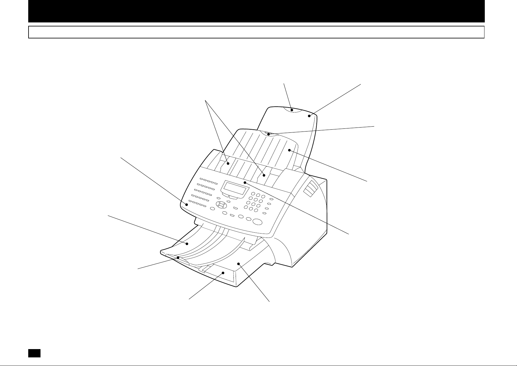
Front View
Recording Paper
Document Guides
Adjust the guides to the edges of
the document to help ensure proper
document alignment and smooth
feeding. (See page 82.)
Exit Tray Extension
Supports long recording
paper after printing.
Recording Paper Exit Tray
Stacks recording paper after
printing. (See page 19.)
Operation Panel
Used to perform programming
and operation of the facsimile
machine. (See page 13.)
Document Exit Tray
Stacks the original
documents after scanning.
Document Exit Tray Extension
Supports long original documents
after scanning. (See page 19.)
Paper Tray
Holds up to 250 sheets of
recording paper.
(See page 20.)
Bypass Tray
Load a sheet of recording
paper. (See page 23.)
Document Support Extension
Supports long original documents
to transmit or copy.
Document Support
Place documents face down on
this tray to transmit or copy.
Operation Panel Release Position
Provides access to the document
scanner area for periodical cleaning or
clearing jammed originals. Grasp the
center of the Control Panel and pull
forward to open. (See page 218.)
02
10
Page 13
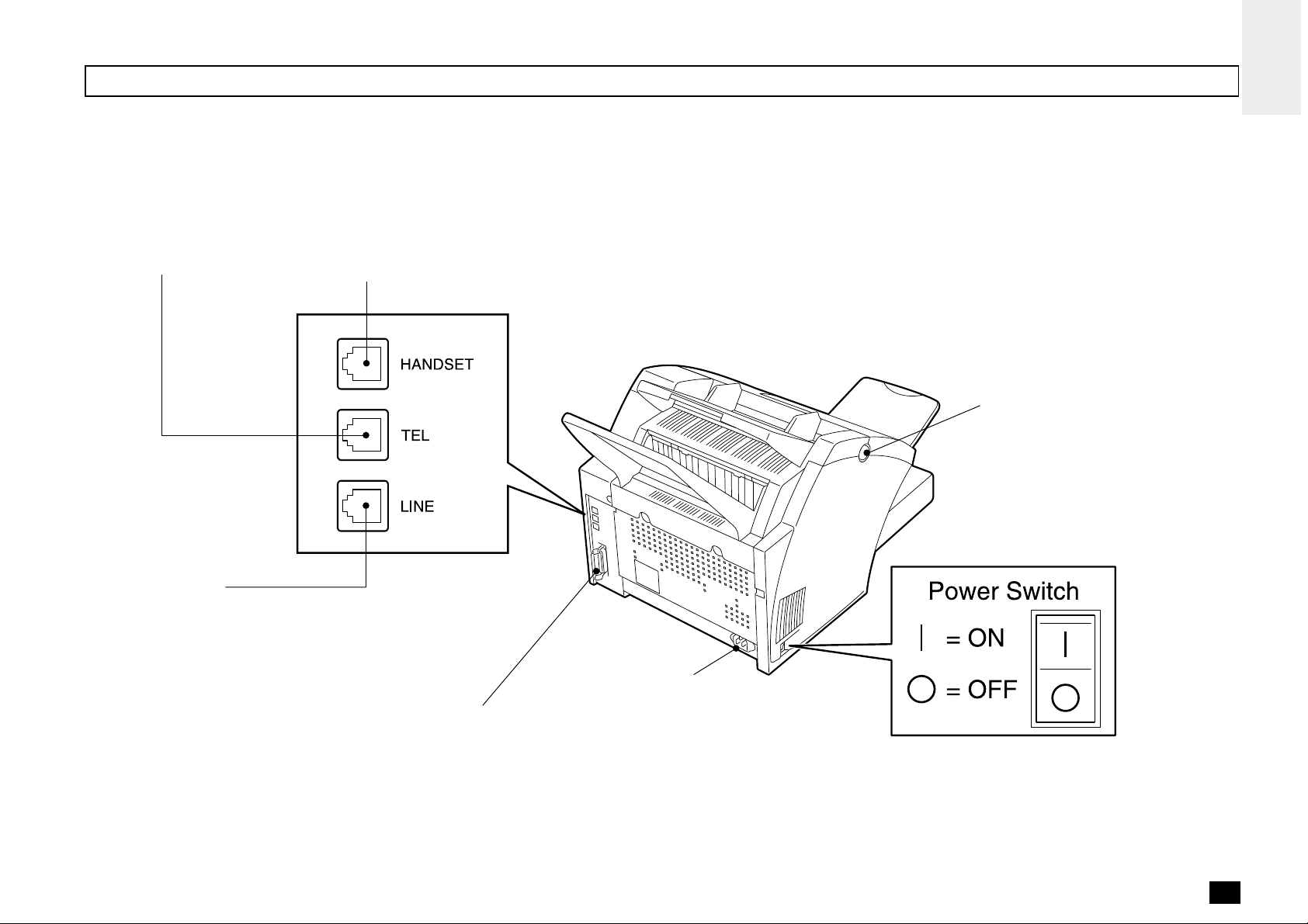
Rear View
External Telephone
Connector
Connection for an External
Telephone set.
(See page 18.)
Handset Connector
Connection for the optional
Handset unit. (See page 18.)
Top Cover Open Button
Provides access to printer section to
replace supplies or to clear paper
jams. (See pages 27, 29 and 220.)
Line Connector
Connection for the telephone
line cord from wall or PSTN
system. (See page 18.)
Centronics PC Interface
This interface is used for connection to
personal computers for Scanning,
Printing and programming various
settings from PC.
AC Inlet
03
11
Page 14
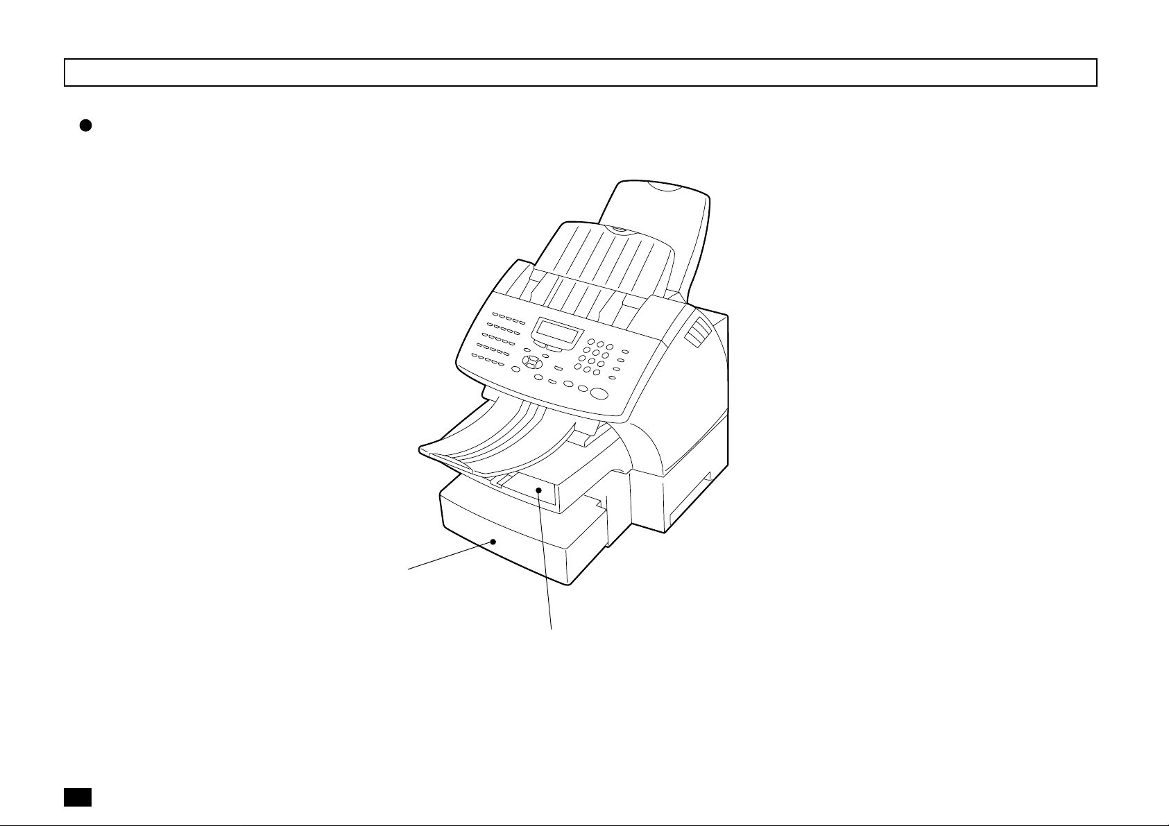
When Optional Recording Paper Tray is Installed
With Optional Recording Paper Tray Installed
12
04
Lower Recording
Paper Tray (Optional)
Upper Recording
Paper Tray
Page 15
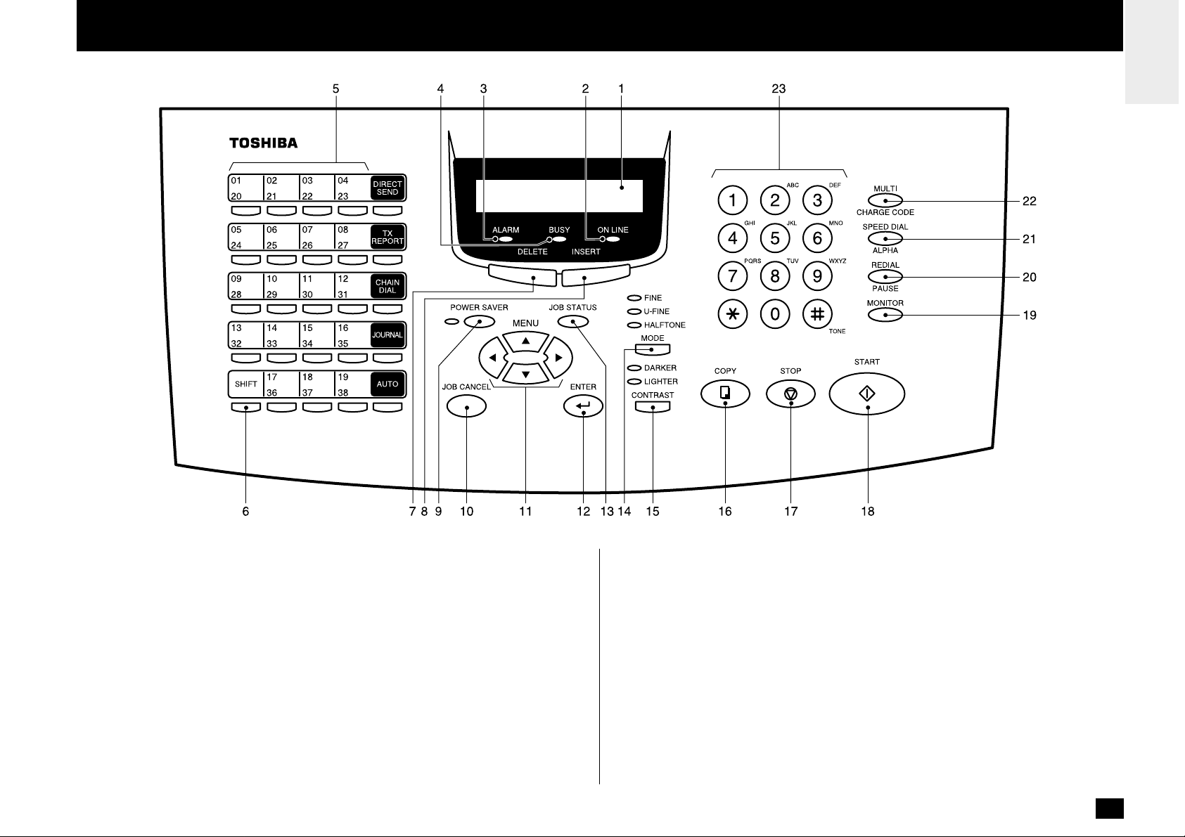
- OPERATION PANEL
1. LCD Display
Display machine status and configuration information for operator viewing and
interaction.
2. ONLINE Lamp
Blinks when communicating between the facsimile unit and a personal computer.
3. ALARM Lamp
Is illuminated when any error occurs (see page 212).
4. BUSY Lamp
Illuminated when communicating using the phone line.
5. One Touch Keys
Allows remote locations to be dialed at the touch of a button (see page 89).
6. SHIFT Key
Press this key prior to selecting the One Touch keys (No.20 to No.38).
7. DELETE Key
This key is used to delete characters in CHARACTER ENTRY mode (see page
36).
8. INSERT Key
This key is used to insert characters in CHARACTER ENTRY mode (see page 36).
9. POWER SAVER key and POWER SAVER Lamp
Press this key to select the Super Power Saver Mode.
Illuminated when the facsimile is in the Super Power Save Mode.
10.JOB CANCEL Key
Used to cancel a job reserved or being performed (see page 110).
13
Page 16

11.Menu Keys ( , , , Keys)
These keys are used to scroll LCD menu prompts (see page 35).
12.ENTER Key
Press this key to enter a selected menu item or select a menu entry.
13.JOB STATUS Key
Displays the communication status of reserved transmissions (see page 109).
14.MODE Key and FINE, U-FINE, HALFTONE Lamps
Select the desired resolution for transmission or copying. When Standard mode is
selected, none of the MODE lamps will be illuminated (see page 83).
15.CONTRAST Key and DARKER, LIGHTER Lamps
Select the desired contrast level of transmit document or copying. When normal
mode is selected, none of the CONTRAST lamps will be illuminate (see page 84).
16.COPY Key
Press this key, with a document in the Document Support, to copy a document
(see page 87).
17.STOP Key
Used to stop operation or cancel system programming. This key is also used to
clear an error condition.
18.START Key
Press this key to start facsimile communication. This key is also used to complete
programming.
Used for accessing Abbreviated, Alphabet, or Group dialing telephone directories
(see pages 90 and 91).
22.MULTI/CHARGE CODE Key
Performs Multi-address Transmissions (Broadcast) or a Multi-polling receptions
(see page 113). This key also used to input the charge code (see page 157).
23.Dial Keypad
Use these 12 keys just like a telephone keypad to dial telephone/facsimile numbers (see page 35).
The dial keys are also used to enter alphanumeric characters for remote parties
names, etc. (see page 36).
The
is also used as the [TONE] Key. The key is helpful to access
various services requiring touch-tone dialing when you are connected to a Rotary
line (see page 108).
19.MONITOR Key
Used to enable the speaker monitor, for monitoring call progress during non
memory document feeder transmissions (see page 98).
20.REDIAL/PAUSE Key
Press this key to redial a facsimile/telephone number if the number was busy on
your first try (see page 108). Or, use this key to enter a pause between telephone
digits when entering a remote facsimile number.
21.SPEED DIAL/ALPHA Key
14
Page 17
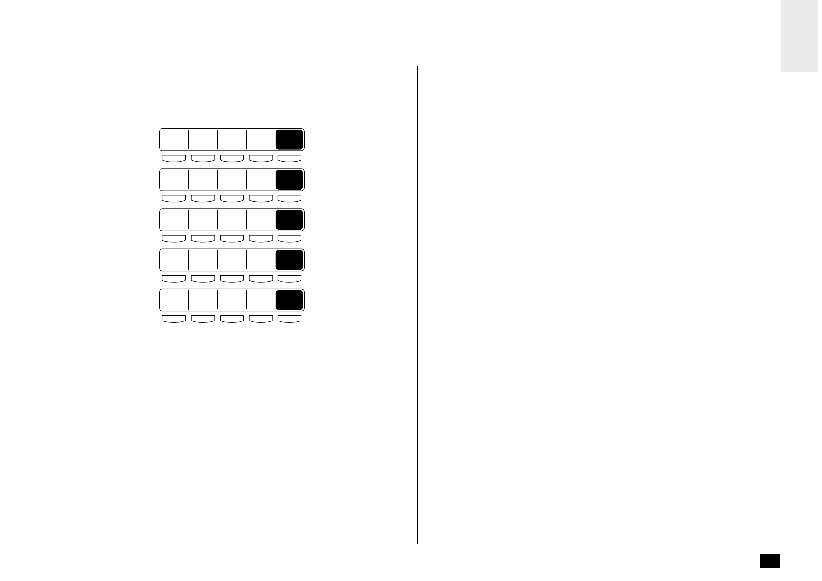
Function Keys
Frequently used functions are pre-assigned to five keys
on the right side of One Touch key panel.
01
02
03
20
05
24
09
28
13
32
SHIFT
21
06
25
10
29
14
33
17
36
22
07
26
11
30
15
34
18
37
04
23
08
27
12
31
16
35
19
38
DIRECT
SEND
TX
REPORT
CHAIN
DIAL
AUTO
JOURNAL
AUTO
DIRECT SEND
Allows transmission direct from the document feeder without scanning the document to memory first (see page 95).
TX REPORT
Press this key to request or disable a Transmission Report for your current transmission job.
CHAIN DIAL
Used to dial a remote party using Chain Dialing (see page 148).
JOURNAL
Used to print communication journals (see page 187).
AUTO
Used to select the reception mode, auto receive, Fax/Tad, Tel/Fax or manual.
15
Page 18
SETUP - UNPACKING
1
Unpack the Carton
2
3
4
2
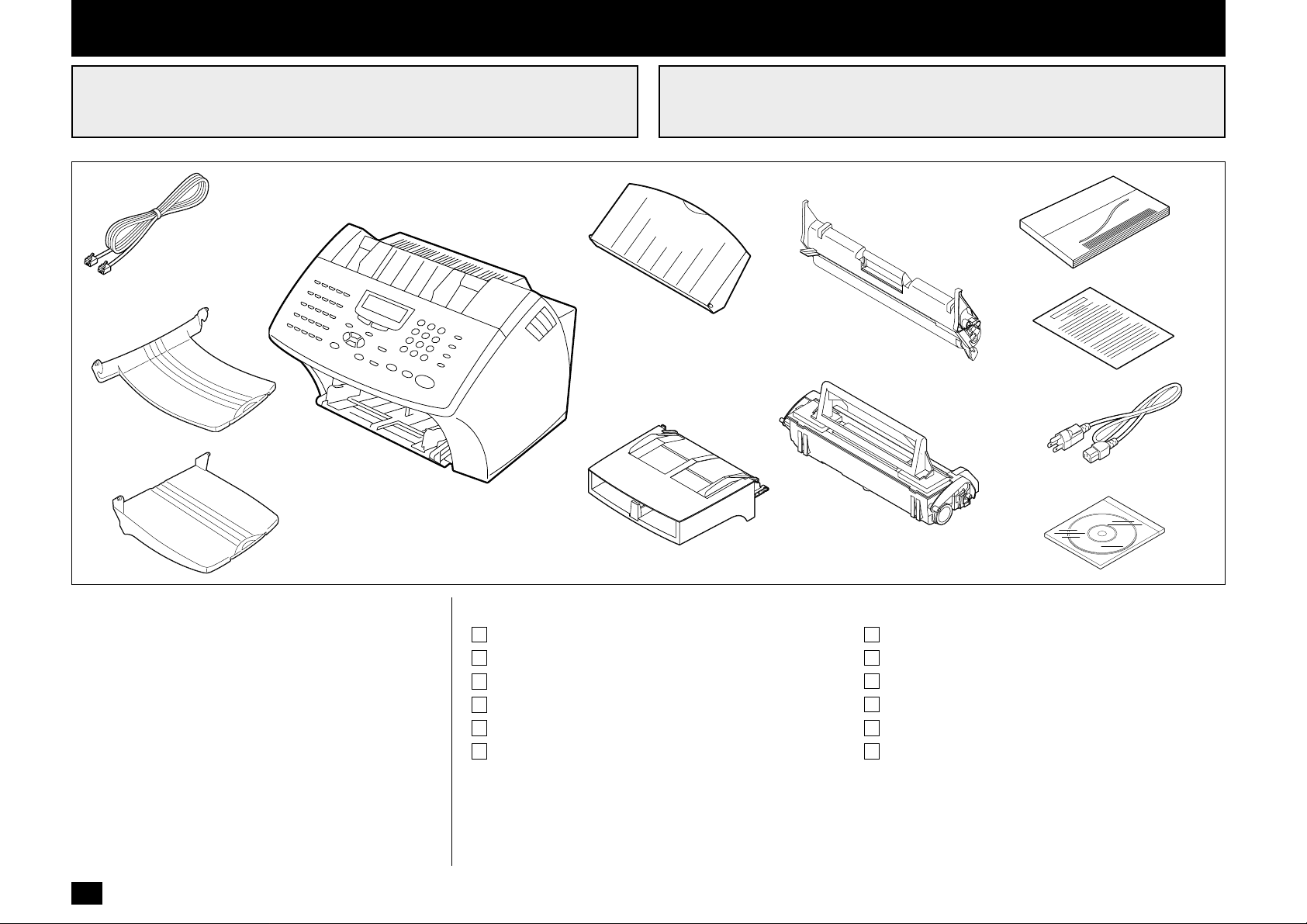
Make Sure All Items are Enclosed
5
1
7
9
10
11
6
8
12
Check the carton and report any damage to the delivery
service. Save the carton and packing materials for future
use.
Check the items in the carton with the following packing
list. If anything is missing, contact your dealer immediately.
16
Packing List
1. Facsimile .................................................. 1
2. Phone Line Cord (Modular Cord).............. 1
3. Document Exit Tray.................................. 1
4. Recording Paper Exit Tray ....................... 1
5. Document Support ................................... 1
6. Paper Tray Assembly
(with Bypass Tray) ................................... 1
7. Drum Unit ................................................. 1
8. Toner Cartridge ........................................ 1
9. Operator’s Manual.................................... 1
10. Warranty Card.......................................... 1
11. AC Power Cord ........................................ 1
12. Toshiba Viewer CD-ROM ......................... 1
Page 19
3
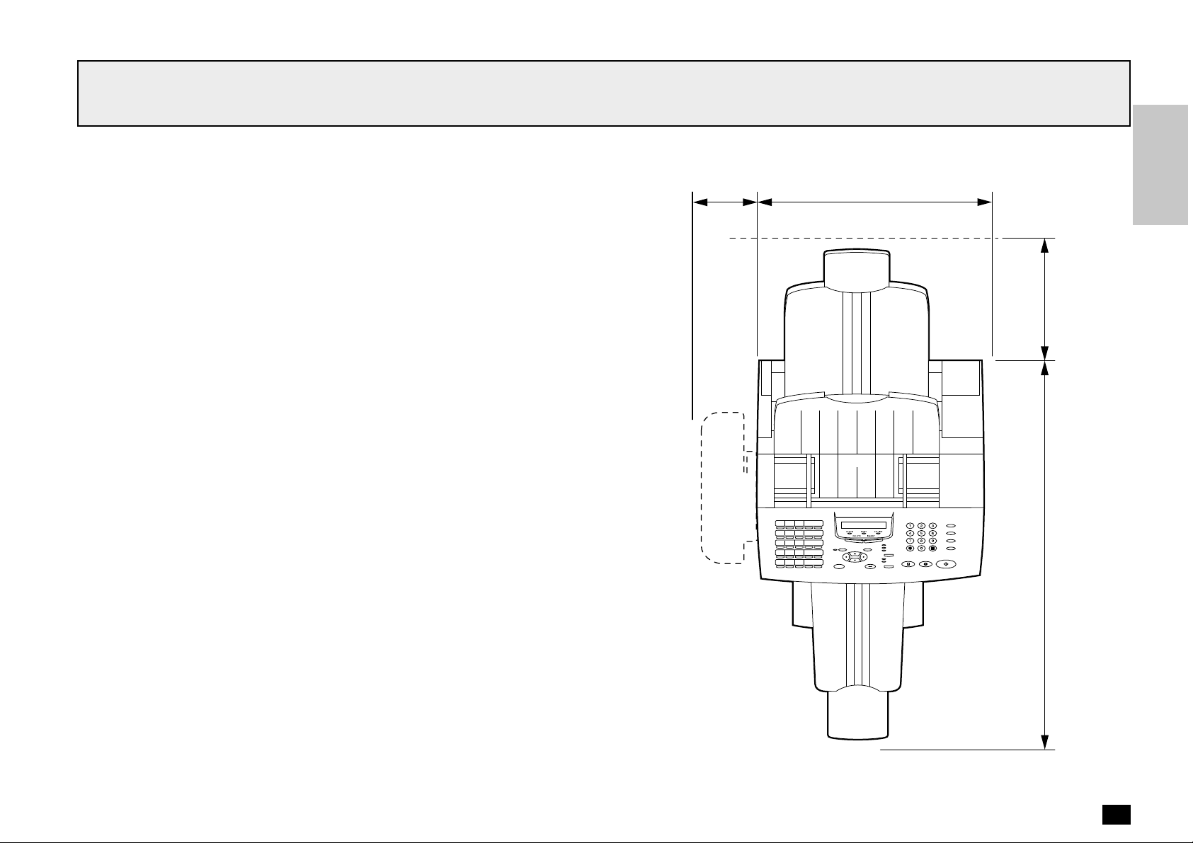
Select a Desirable Location
The unit should be installed:
• On a horizontal surface.
• Away from direct sunlight, dust, extreme heat and humidity, and vibration.
• Away from sources of strong electrical or magnetic fields, such as televisions or
radios.
• Within reach of an electrical outlet. Use an outlet not shared with equipment that
generates electrical noise or consumes large amounts of electricity, such as an air
conditioner, or a copier.
• Within reach of a telephone connection. Use a dedicated, single-line telephone
connection.
• Allow for adequate ventilation. The rear and sides of the unit need to be clear to
allow proper air flow to the unit’s power supply.
120 mm
(4.72 inches)
400 mm
(15.74 inches)
250 mm (9.84 inches)
707 mm (27.83 inches)
Height: 650 mm (25.6 inches)
17
Page 20
- FACSIMILE MACHINE INSTALLATION
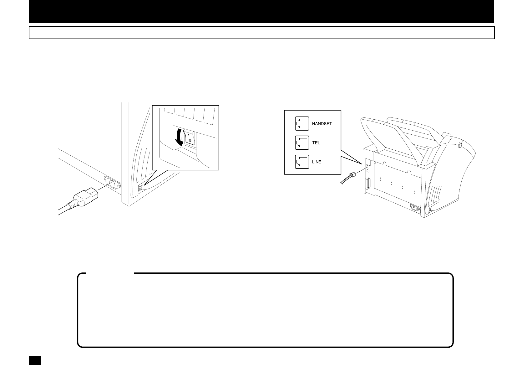
Connecting Y our TOSHIBA Facsimile
Make sure that the Power Switch is turned OFF.
Plug in the power cord as in the figure below.
Power Cord
Power Switch
OFF
Connect the telephone line cord (modular cord) to the “LINE” connector.
Connect the external telephone set (if desired) to the “TEL” connector.
Connect the optional Handset (if equipped) to the “HANDSET” connector
18
.
19
18
WARNING
• Never install telephone wiring during a lightning storm.
• Never install telephone jacks in wet locations unless the jack is specifically designed for wet locations.
• Never touch uninsulated telephone wires or terminals unless the telephone line has been disconnected at the network interface.
• Use caution when installing or modifying the telephone lines.
• Avoid using a telephone (other than a cordless type) during an electric storm. There may be a remote risk of electric shock from
lightning.
• Do not use the telephone to report a gas leak in the vicinity of the leak.
Page 21
Recording Paper Exit Tray
Document Support
Document Exit Tray
Recording Paper Tray
Bypass T ray
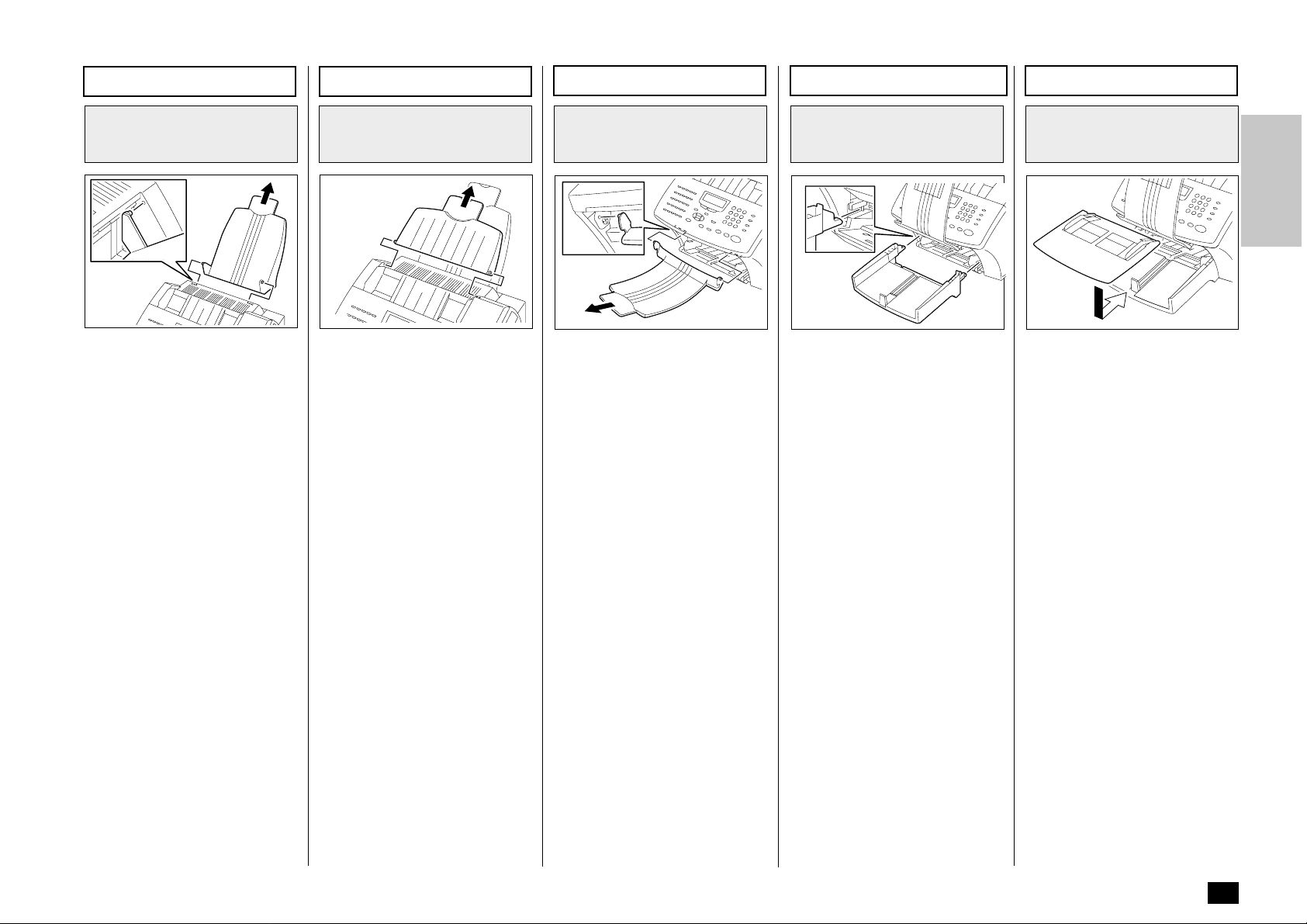
Recording Paper Exit
Tray Installation
20
Fit the tabs of the Recording
Paper Exit Tray into the slots on
the back side of the unit.
• Do not place heavy objects
on the Recording Paper Exit
Tray or apply strong force.
• Extend the Recording Paper
Exit Tray Extension for long
recording paper.
Document Support
Installation
22
Fit the tabs of the Document
Support into the slots on the top
side of the unit.
• Do not place heavy objects
on the Document Support or
apply strong force.
• Extend the Document Support Extension for long documents.
NOTE:
It may be necessary to gently bow the base of the support toward you as you place
the support into position.
Document Exit Tray
Installation
Fit the tabs of the Document
Exit Tray into the slots on the
front side of the unit.
• Do not place heavy objects
on the Document Exit Tray
or apply strong force.
• Extend the Document Exit
Tray Extension for long
documents.
Recording Paper Tray
Installation
21
Lift the Document Exit Tray so
that it catches on the under side
of the Operation Panel.
Place the hooks of the Recording Paper Tray to the guides on
the front side of the unit.
• Do not place heavy objects
on the Recording Paper Tray
or apply strong force.
Bypass Tray Installation
23
Place the Bypass Tray on the
Recording Paper Tray.
• Do not place heavy objects
on the Bypass Tray or apply
strong force.
24
19
Page 22
- INITIAL PRINTING SUPPLIES INSTALLATION
Recording Paper Installation (Recording Paper Tray)
About Recording Paper:
• Use only recommended paper brands to optimize your
facsimile performance. Contact your authorized TOSHIBA dealer for more information.
• Remove the recording paper
when storing or relocating
your facsimile.
• Avoid using damaged, folded
or misaligned recording paper. Use of damaged paper
could cause double feeding
or paper jamming.
• Use of damp recording paper
will cause poor printing over
all or part of the image area.
If the paper is excessively
moist, print quality may become uneven and voiding
may occur. Replace the paper, should this condition exist.
• Do not add paper on top of
the paper already in the machine. If you wish to add paper, first remove the existing
paper. Then stack the existing paper with the new paper
before inserting into the machine.
About Paper Sizes:
• Your TOSHIBA facsimile has
been preset to accept letter
size recording paper.
In the event that you receive
a legal-size (8.5”x14”) reception, it will automatically be
reduced to fit onto letter-size
(8.5”x11”) paper.
• If you receive only legal-
size receptions and do not
wish them to be automatically reduced: Load the le-
gal-size paper in the tray.
• If you receive a mixture of
letter and legal-size receptions, and you do not wish
your legal receptions to be
automatically reduced:
Add an optional recording
paper tray to support both
letter and legal-size paper.
With the second recording
paper tray, your TOSHIBA
facsimile will automatically
select the appropriate paper
size to match the pages you
receive.
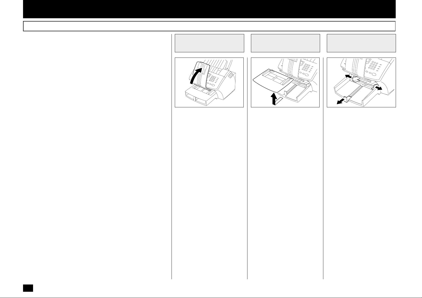
Pull Up the
1
Document Exit Tray
25 30
Pull up the Document Exit Tray.
If you raise the tray high
enough, it will latch onto the underside of the Operation Panel.
CAUTION:
• Do not place heavy objects
on the Document Exit Tray
or apply strong force.
Remove the Bypass
2
Tray
Remove the Bypass Tray from
Recording Paper Tray.
Open the Paper
3
Guides
Open the Paper Guides.
31
20
Page 23
Recording Paper Installation (Recording Paper Tray) - continued
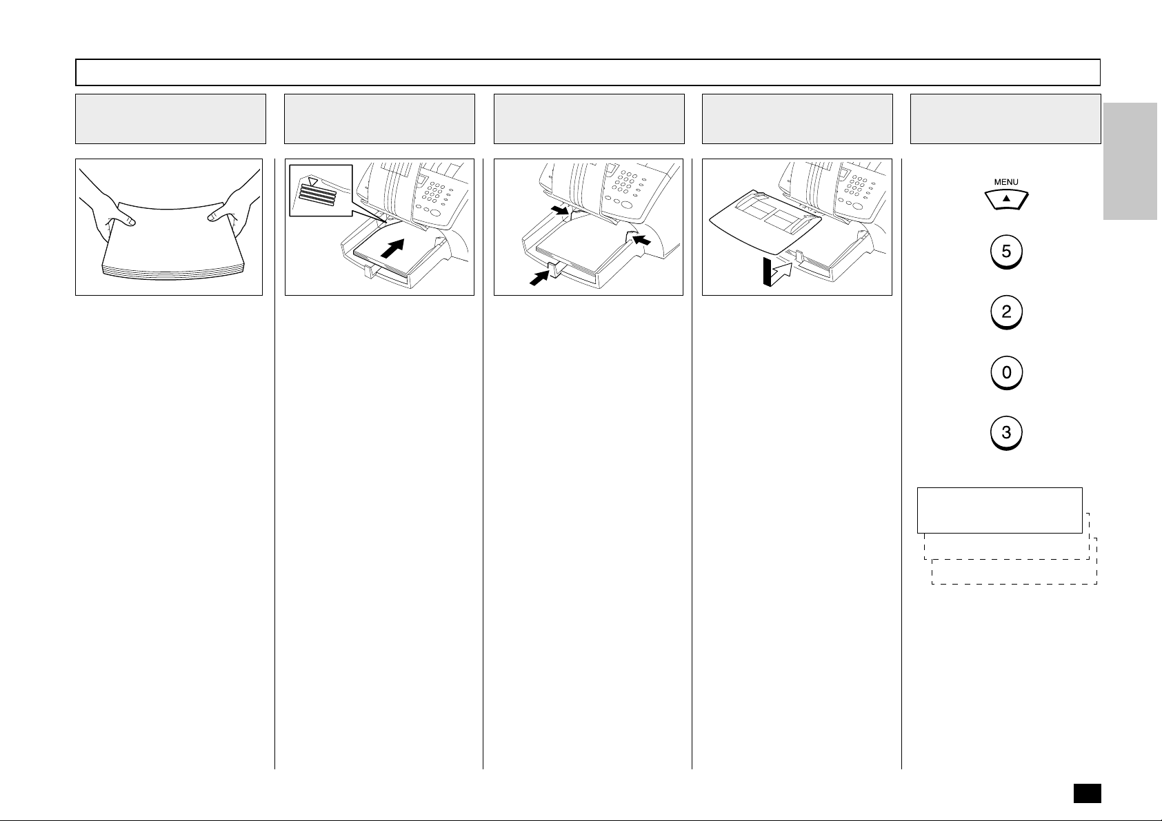
Prepare Recording
4
Paper Sheets
32
Prepare new recording paper
sheets by holding both ends
and flexing several times.
This will separate the sheets
and provide optimum feeding.
Align the stack so that all four
corners are neatly aligned.
Be sure to load the recording
paper in accordance with any
paper manufacturer’s printing
side instruction. Some papers
have a preferred image side.
This image side should be
placed face up in the Recording
Paper Tray.
Install the
5
Recording Paper
33 34
Place the recording paper stack
into the tray.
NOTES:
• Do not exceed the upper
stack limit line as this may
cause paper mis-feeds.
• Do not add paper on top of
the paper already in the machine.
Adjust the Paper
6
Guides
Adjust the Paper Guides to fit
the size of the Recording Paper.
Replace the Bypass
7
Tray and Document
Exit Tray
36
Replace the Bypass Tray and
Document Exit Tray.
CAUTION:
Do not place heavy objects
on the Document Exit Tray
or apply strong force.
Display the Paper
8
Size Menu
Press:
+
+
+
+
The menu below displays:
PAPER SIZE (TRAY 1)
1.LT
2.A4
3.LG
NOTE:
If you install legal size paper
but fail to select “3.LG” at
this point, the machine will
think letter size paper is installed. False “Paper Jam”
failures will occur when the
legal size paper is fed into
the printer.
21
Page 24
Recording Paper Installation (Recording Paper Tray) - continued
Select the Paper
9
Size
Select the paper size of the Recording Paper Tray.
To select letter size, press:
To select A4 size, press:
To select legal size, press:
COMPLETED
Displayed for 2 seconds
Return to the
10
Standby Mode
Press to return to the
Standby Mode.
Returns to display the SETUP
menu screen.
22
Page 25

Recording Paper Installation (Bypass Tray)
Pull Up the
1
Document Exit Tray
25 26
Pull up the Document Exit Tray.
If you raised the Document Exit
Tray high enough, it will catch
the underside of the Operation
Panel.
CAUTION:
Do not place heavy objects
on the Document Exit Tray
or apply strong force.
Open the Paper
2
Guides
Open the Paper Guides.
Insert the Recording
3
Paper
27
Insert a one sheet of paper on
the Bypass Tray.
CAUTION:
Do not insert more than one
sheet of paper on the Bypass Tray.
It will cause a paper jam.
Adjust the Paper
4
Guides
28
Adjust the Paper Guides so that
both sides of the paper are secure.
Return the
5
Document Exit Tray
29
Return the Document Exit Tray
to its normal position.
23
Page 26
Recording Paper Installation (Optional Recording Paper Tray)
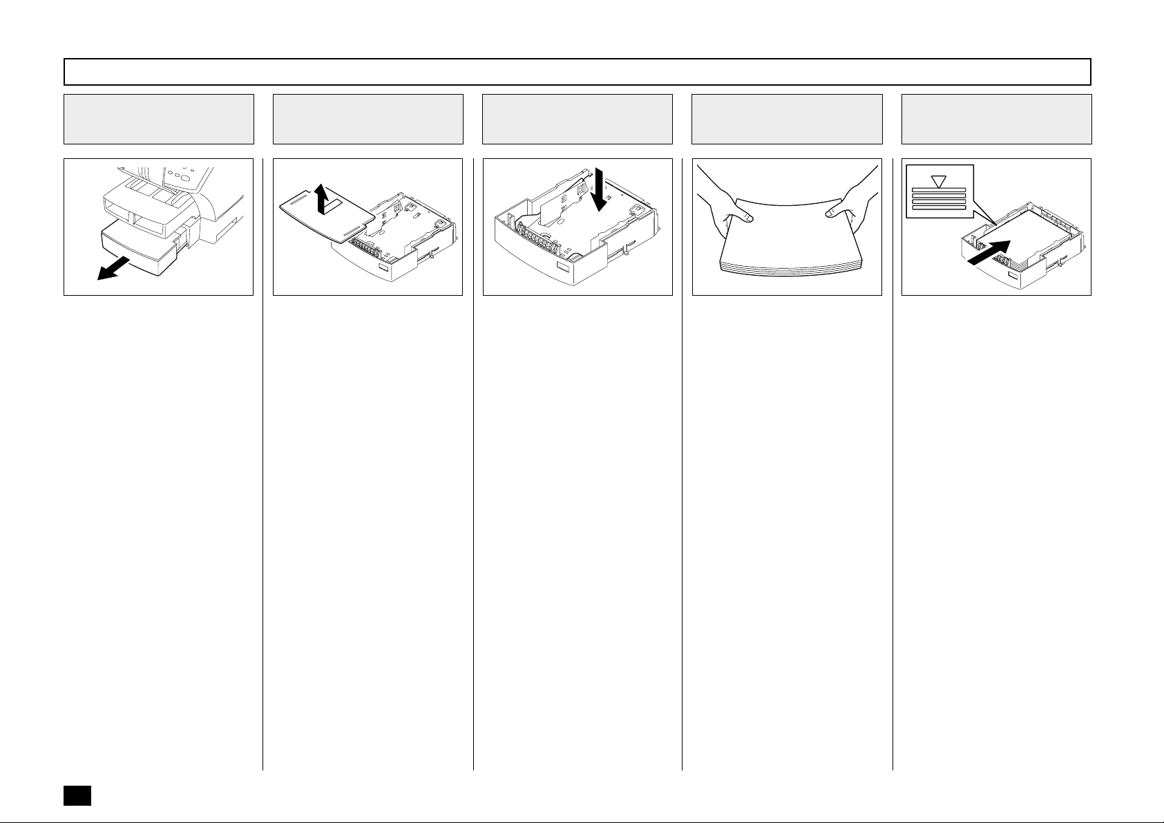
Remove the Optional
1
Recording Paper
Tray
73 74
Remove the Optional Recording
Paper Tray.
Remove the
2
Optional Tray Cover
Remove the Optional Tray
Cover.
Press Down the
3
Paper Pressure Plate
75
Press the Paper Pressure Plate
down until it clicks.
Prepare Recording
4
Paper Sheets
32
Prepare new recording paper
sheets by holding both ends
and flexing several times.
This will separate the sheets
and provide optimum feeding.
Align the stack so that all four
corners are neatly aligned.
Be sure to load the recording
paper in accordance with any
paper manufacturer’s printing
side instruction. Some papers
have a preferred image side.
This image side should be
placed face up in the Recording
Paper Tray.
NOTE:
There are two types of the
Optional Recording Paper
Tray, one for A4-size paper
and another for letter-size
paper. Use the Tray meeting
your paper size.
Install the Recording
5
Paper
76
Place the recording paper stack
into the tray.
NOTES:
• Do not exceed the upper
stack limit line as this may
cause paper misfeeds.
• Make sure that the paper is
seated under the two separation claws on the back side
of tray.
• Be careful not to damage the
claws of the Recording Paper Tray.
• Do not add paper on top of
the paper already in the machine.
24
Page 27
Recording Paper Installation (Optional Recording Paper Tray) - continued
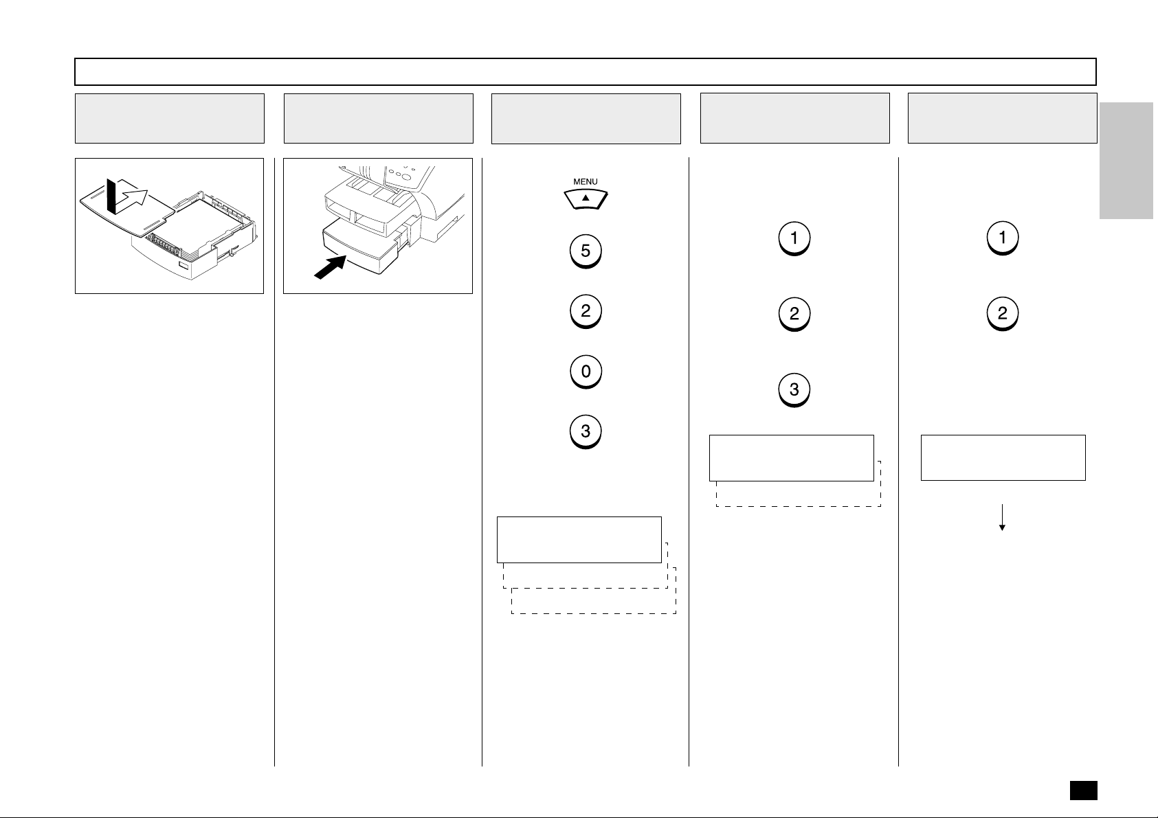
Replace the Optional
6
Tray Cover
77 78
Replace the Optional Paper
Tray Cover.
Insert the Optional
7
Recording Paper Tray
Insert the Optional Recording
Paper Tray all the way into the
machine.
NOTE:
As the tray is inserted, listen
for the sound of the paper
pressure plate moving up
into position.
Display the Paper
8
Size Menu
Press:
+
+
+
+
The menu below displays:
Select the Paper Size
9
of the Recording
Paper Tray
Select the paper size of the Recording Paper Tray.
To select letter size, press:
To select A4 size, press:
To select legal size, press:
PAPER SIZE (TRAY 2)
1.LT
2.A4
Select the Paper Size
10
of the Optional
Recording Paper Tray
Select the paper size of the Optional Recording Paper Tray.
To select the letter size, press:
To select the A4 size, press:
COMPLETED
Displayed for 2 seconds
PAPER SIZE (TRAY 1)
1.LT
2.A4
3.LG
Returns to display the SETUP
menu screen.
25
Page 28

Recording Paper Installation (Optional Recording Paper Tray) - continued
Return to the
11
Standby Mode
Press to return to the
Standby Mode.
26
Page 29
Drum Unit and Toner Cartridge Installation
Open the Top Cover
1
37 45
Push the Top Cover Open Button and open the Top Cover.
Install the Drum Unit
2
Install the Drum Unit into the
machine, aligning the guides of
the unit with the grooves inside
the machine.
Color coordinate “1” labels have
been affixed to the Drum Unit
and to the inside of the machine. Install the Drum Unit by
aligning these labels.
Make sure the Drum Unit is inserted inside the machine as far
as it will go.
Prepare a Toner
3
Cartridge
39
Mix the Toner by shaking the
Toner Cartridge back and forth.
NOTE:
Use only specified TOSHIBA
Toner Cartridges.
CAUTION:
Hold the Toner Cartridge by
the green handle.
Install the Toner Cartridge
4
2
222
40
Holding onto the Toner Cartridge’s handle, lower it into the
machine. Make sure that the
four pins (two on each side) fit
into the grooves inside the machine.
Color coordinated “2” labels
have been affixed to the Toner
Cartridge and to the inside of
the machine. Install the Toner
Cartridge by aligning these labels.
As the Toner Cartridge is lowered into the machine, its handle will rotate first to the rear of
the machine and then to the
front.
The cartridge will click into place
when it is completely installed.
41
42
27
Page 30

Drum Unit and Toner Cartridge Installation - continued
Close the Top Cover
5
43
Press down on the Top Cover
until a “Click” is heard to ensure
the latches engage.
28
Page 31

- PRINTING SUPPLIES REPLACEMENT
Toner Cartridg e Replacement
Replacement Toner Kits for your TOSHIBA facsimile include a Toner Cartridge.
Your TOSHIBA facsimile has been designed to display a two stage
alert to replace Toner once it has been depleted.
The first stage is a “TONER LOW” warning that alerts you that the
Toner is low and should be replaced at your earliest convince.
The unit will continue to receive and print facsimile messages during
this stage.
The second stage is a “TONER EMPTY” notice. When this message
is displayed, the machine can no longer print documents. Receptions will be stored in memory until the Toner has been replaced.
It is recommended to replace the Toner Cartridge whenever the
“TONER LOW” message is displayed using the following procedure.
Open the Top Cover
1
Push the Top Cover Open Button and Open the Top Cover.
Remove the Toner
2
Cartridge
38 3937
Remove the Toner Cartridge.
CAUTION:
Always hold the Toner Cartridge by the green handle.
NOTE:
Avoid touching the toner to
your clothing since toner
cannot be removed easily.
If the toner sticks to your
clothing, immediately rinse
out the toner with cold water.
Prepare a New
3
Toner Cartridge
Remove the new Toner Cartridge from its shipping carton.
Mix the Toner by shaking the
new Toner Cartridge back and
forth.
NOTE:
Use only specified TOSHIBA
Toner Cartridges.
29
Page 32

Toner Cartridg e Replacement - continued
Install the New Toner Cartridge
4
2
222
40
Holding onto the Toner
Cartridge’s handle, lower it into
the machine. Make sure that the
four pins (two on each side) fit
into the grooves inside the machine.
Color coordinated “2” labels
have been affixed to the Toner
Cartridge and to the inside of
the machine. Install the Toner
Cartridge by aligning these labels.
Close the Top Cover
5
41
42
43
Press down on the Top Cover
until a “Click” is heard to ensure
the latches engage.
As the Toner Cartridge is lowered into the machine, its
handle will rotate first to the rear
of the machine and then to the
front.
The cartridge will click into place
when it is completely installed.
30
Page 33

Drum Unit Replacement
Replacement Drum Kits for your
TOSHIBA facsimile include a
Drum Unit.
Your TOSHIBA facsimile has
been designed to display a twostage alert to replace the Drum
Unit once it has been depleted.
The first stage is a “DRUM UNIT
WARNING” that alerts you that
the Drum Unit is near its end of
life and should be replaced at
your earliest convince. The unit
will continue to receive and print
facsimile messages during this
stage.
The second stage is the “REPLACE DRUM UNIT” notice.
When this message is displayed, the machine can no
longer print documents. Receptions will be stored in memory
until the Drum Unit has been
replaced.
For the purpose of determining
Drum usage;
Each legal-size sheet of paper
counts as 1.3 letter-size sheets
of paper.
STORAGE NOTES:
The Drum Unit is a very important part of this facsimile.
Handle it with care as shown
below.
Keep the Drum Unit within a
temperature range of 0-35°C
(32-95°F) and a humidity
range of 20-80%RH (without
condensation).
Do not store or use the Drum
Unit in an environment where
the temperature changes excessively.
Do not touch the light sensitive drum because its surface
will be easily damaged.
Do not place the light sensitive drum in a location where
it is exposed to direct sunlight
or high intensity light (more
than 200 lx) such as near a
window.
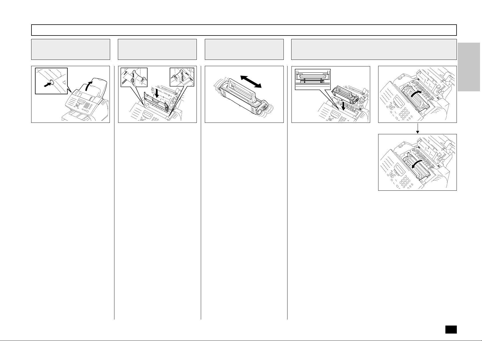
Open the Top Cover
1
37
Push the Top Cover Open Button and open the Top Cover.
Remove the Toner Cartridge and Drum Unit
2
38
Remove the Toner Cartridge and Drum Unit.
CAUTION:
Always hold the Drum Unit and Toner Cartridge by their green
handles. Do not expose the green drum to light for more than 3
minutes. Never expose it to direct sunlight or touch the green
drum. Damage or poor print quality may result.
NOTE:
Avoid touching the toner to your clothing since toner cannot be
removed easily.
If the toner sticks to your clothing, immediately rinse out the
toner with cold water.
44
31
Page 34

Drum Unit Replacement - continued
Install the New Drum
3
Unit
45
Install the new Drum Unit into
the machine, aligning the guides
of the Unit with the grooves inside the machine.
Color coordinated “1” labels
have been affixed to the Drum
Unit and to the inside of the machine. Install the Drum Unit by
aligning these labels.
Make sure the Drum Unit is inserted inside the machine as far
as it will go.
IMPORTANT:
• Never touch the photoconductive drum (the green surface) of the Drum Unit. If the
surface is scarred or
scratched, it will cause print
quality problems.
Install the Toner Cartridge
4
2
222
40
Holding onto the Toner
Cartridge’s handle, lower it into
the machine. Make sure that the
four pins (two on each side) fit
into the grooves inside the machine.
Color coordinated “2” labels
have been affixed to the Toner
Cartridge and to the inside of
the machine. Install the Toner
Cartridge by aligning these labels.
As the Toner Cartridge is lowered into the machine, its
handle will rotate first to the rear
of the machine and then to the
front.
The cartridge will click into place
when it is completely installed.
Close the Top Cover
5
Reset the Drum
6
Counter
Perform the following procedure
to reset the Drum Unit counter
after you replace the Drum Unit.
Press:
41
Press down on the Top Cover
until a “Click” is heard to ensure
the latches engage.
42
43
RESET DRUM COUNT
2.NO
1.YES
+
+
+
+
• Do not expose the photoconductive drum of the Drum
Unit to light for more than 3
minutes. If the Drum Unit is
to be left anywhere outside
the facsimile, be certain to
cover it with cloth, paper,
etc.
32
Page 35

Drum Unit Replacement - continued
Reset the Drum
6
Counter - continued
Press:
RESET DRUM COUNT
ARE YOU SURE ?
Press:
COMPLETED
Displayed for 2 seconds
Return to display the SETUP
menu screen.
Return to the
7
Standby Mode
Press to return to the
Standby Mode.
NOTE:
You must reset the drum
counter when you replace
the Drum Unit.
Never perform this operation
on any other occasion.
33
Page 36

- QUICK START
This section provides several
quick start programming steps
to prepare your new facsimile
for immediate use.
These procedures are a simple
version of the detailed procedures listed in the manual. Next
to each procedure heading is a
convenient page number reference for the detailed procedure.
Should you have any difficulty
with these simple procedures,
refer to the pages listed for
more information.
It is highly recommended that
you take the time to read
through this manual to get the
most from your new TOSHIBA
facsimile.
Terminal ID
Setting the Terminal ID (Page 42)
1
Press: , ,
NAME (40MAX)
[ ]
Enter your user ID (company
name) using the Numeric Keypad, press:
COUNTRY CODE
1.YES
2.NO
FAX NUMBER (20MAX)
[ ]
Enter your facsimile’s telephone
number, press:
COMPLETED
Displayed for 2 seconds
INITIAL SETUP
3.TERMINAL ID
Transmitting
Sending a Facsimile
2
(Page 93)
Load your document face down
into the Document Support.
MAY-17 09:43 AM 100%
AUTO RECEIVE
Dial the remote facsimile using
the Dial Keypad located on the
Operation Panel. Remember to
include any access numbers
such as 9 or press the
after the access number if you
normally have to wait for a dial
tone.
Receiving
Receiving a
3
Facsimile (Page 104)
Your TOSHIBA facsimile has
been preset from the factory to
receive facsimile messages. No
special setup is required to receive facsimile messages.
34
If you communicate internationally, select:
Otherwise, select:
Press:
After the remote facsimile number has been entered into the
keypad, press the green START
key.
Page 37

- USER INTERFACE OPERATION
Menu Operation
Various functions of this facsimile can be used by selecting
menu items displayed in the
LCD window. Performing operations or settings by selecting
menu items is called “Menu Operation.” The menus use a multilayered structure.
Starting Menu Operation:
When the facsimile is in the
Standby Mode, press
start Menu Operation.
(In the Standby Mode, the display shows the date, time and
residual memory % on the first
row and the receive mode on
the second row as shown be-
MAY-17 09:43 AM 100%
AUTO RECEIVE
to
Keys Used in Menu Operation
[ ] Key
] Key
[
[
[
[ENTER] Key or [START] Key
or
Press this key to enter the Menu Operation or to scroll up the menu selections.
Press this key to scroll down the menu selections.
] Key
Press this key to display the preceding menu screen or to move the cursor to the left.
] Key
Press this key to display the sub-menu screen or to move the cursor to the right.
When the displayed item has sub-items, pressing this key operates the same as the [
When the displayed item is the end item, press this key to complete the item selection.
] Key.
low.
Completing or Canceling
Menu Operation:
When you have reached the
end of a programming step or
wish to cancel a programming
procedure, press
turn to the Standby Mode.
to re-
Dial Keypad [1] to [0] Keys
Used to enter desired information or to select options.
[STOP] Key
Used to exit the Menu Operation and return to the Standby Mode.
35
Page 38

Character Entry
When programming and registering the Autodialer numbers or
names, you will need to enter alphanumeric characters.
This section helps you understand how to easily enter the
characters.
Keys Used in Character Entry
[INSERT] Key
Inserts characters before the selected
(underlined) character.
[DELETE] Key
Deletes the selected (underlined) character.
] Key
[
Moves the cursor to the right. If pressed
without entering a character, it inserts a
space.
] Key
[
Moves the cursor to the left.
The dial keypad is used to enter alphanumeric characters. Both U.S. and Foreign
alphanumeric characters may be selected
with each Numeric Key. The U.S. characters
are listed for your convenience above each
key. By pressing the Numeric Key multiple
times, you can scroll through all characters
assigned to a particular key (see table below).
Entry Procedure
NAME (20 MAX)
[ ]
Press twice to display “N.” Note that “M” was displayed on the first press followed by “N” on the second.
NOTE: If the next character is located on the same key
as the preceding character, press the
move the cursor to the next position. Otherwise
press the next desired key and the cursor will
automatically move to the right.
NAME (20 MAX)
[N ]
Press
NAME (20 MAX)
[NE ]
Press
2 times for E.
1 time for W.
An example to enter “NEW YORK”:
Press 3 times for Y.
NAME (20 MAX)
[NEW Y ]
Press
NAME (20 MAX)
[NEW YO ]
key to
3 times for O.
36
NAME (20 MAX)
[NEW ]
Press
insert a blank space.
NAME (20 MAX)
[NEW ]
2 times to
Press
NAME (20 MAX)
[NEW YOR ]
Press 2 times for K.
NAME (20 MAX)
[NEW YORK ]
3 times for R.
Page 39

Character Entry - continued
Character Correction
Replacing Characters
NAME (20 MAX)
[NEW YOPK ]
NAME (20 MAX)
[NEW YORK ]
Deleting Characters
NAME (20 MAX)
[NEEW YORK ]
Using / , position the cursor under the character to be corrected.
Input the correct character (“R” in this example) by
pressing
change.
Using / , position the cursor under the character to be deleted.
3 times. Press to save your
Inserting Characters
NAME (20 MAX)
[NEW YRK ]
NAME (20 MAX)
[NEW YRK ]I
NAME (20 MAX)
[NEW YORK ]I
Using / , position the cursor under the
point of insertion and press
The message “[ I ]” is displayed on the right end of
the second row.
Enter the desired character(s) (“O” in this example).
The character(s) will be inserted without deleting
other characters in the line. Press
your change.
.
to save
NAME (20 MAX)
[NEW YORK ]
Delete the character by pressing
to save your change.
. Press
37
Page 40
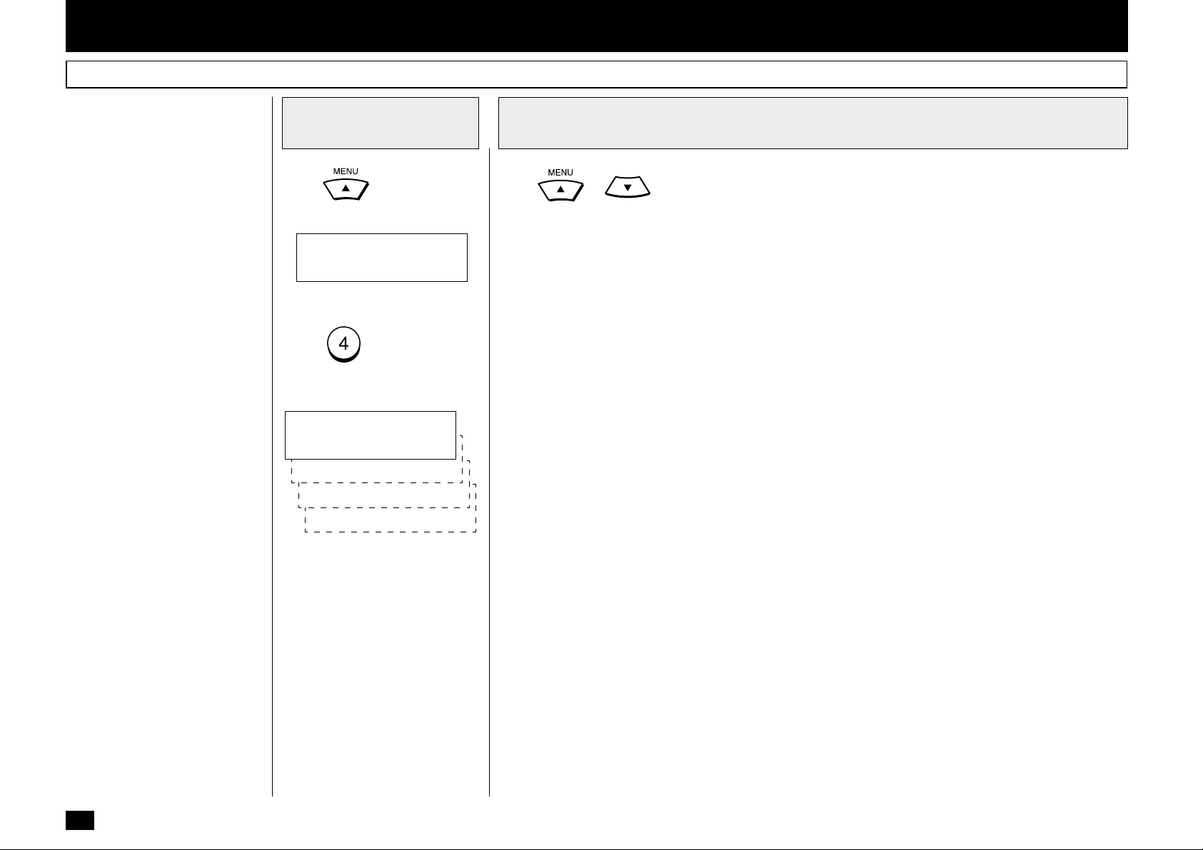
- INITIAL SETUP
Initial Setting Summary
This facsimile has several user
initial settings.
For your convenience, a quick
reference summary of all user
initial settings is shown on the
right.
Each of these initial settings is
discussed in detail throughout
the remainder of this section.
Use the following procedures to
access one or more of these initial settings.
Enter the
1
Configuration Menu
Press
Screen displays.
MENU
1.FAX FEATURES
Press to enter INITIAL
SETUP. The Installation sub-
menu displays.
INITIAL SETUP
1.LANGUAGE
2.DATE & TIME
3.TERMINAL ID
4.DIAL TYPE
. The initial Menu
Select the Desired Initial Setting (1-4)
2
Press
through 4 from the list below. The detailed initial setting procedure for each setting is shown in
parentheses after the initial setting.
1. LANGUAGE - (Page 39) - Selects ENGLISH*, FRENCH or SPANISH display and printing.
2. DATE & TIME - (Page 40) - Sets the Month, Day, Year & Time for your machine. You may select to
use the 24-hour or the 12-hour format for the time.
3. TERMINAL ID - FCC MANDATORY - (Page 42) - Sets the Terminal ID (Company Name &
Facsimile Number) for your machine.
4. DIAL TYPE - (Page 44) - Configures your machine for use with Touch Tone (MF)* or Rotary Dial
(DP) telephone service.
NOTE: * indicates the factory default setting.
or until the desired Initial Setting is displayed or enter the desired Initial Setting 1
38
Page 41

Language Selection
You can select the language
used on the LCD display and all
reports printed by your facsimile. English, French, and
Spanish are available.
To display the SETUP menu,
press:
+
INITIAL SETUP
1.LANGUAGE
Display the
1
LANGUAGE Menu
Display
INITIAL SETUP
1.LANGUAGE
Using or and
press:
or
LANGUAGE
1.ENGLISH
2.ESPAÑOL
Select the Desired
2
Language
Select the desired language.
(for ENGLISH)
(for ESPANOL)
(for FRANCAIS)
COMPLETED
Returns to display the Standby
menu screen.
3.FRANÇAIS
39
Page 42

Date and Time Setting
This facsimile displays the current date and time when in the
Standby Mode. It also uses this
time for maintaining internal list
and reports. Follow this procedure to set the time and date.
To display the SETUP menu,
press:
+
INITIAL SETUP
1.LANGUAGE
Display the DATE &
1
TIME Menu
Display
INITIAL SETUP
2.DATE & TIME
Using or and
press:
or
DATE
[04-15-2000]
Enter the Date Data
2
Move the cursor to the desired
position using the following
keys.
or
Enter the date.
When the correct date is entered, press:
Select the Date
3
Format
Select the date format for display and print.
(for Month/Day/Year 4-digit)
(for Day/Month/Year 4-digit)
(for Year 4-digit/Month/Day)
MONTH FORMAT
2.NAME
1.NUMERIC
Select the Month
4
Format
Select the month format.
(for NUMERIC, such as 01, 02,
03 ...)
(for NAME, such as JAN, FEB,
MAR ...)
TIME FORMAT
2.12 HOUR
1.24 HOUR
40
DATE FORMAT
1.MM-DD-YYYY
2.DD-MM-YYYY
3.YYYY-MM-DD
Page 43

Date and Time Setting - continued
Select the Time
5
Format
Select the time format.
(for 24-hour format)
TIME
[09:43]
(for 12-hour format) default
TIME
[09:43AM]
Enter the Time Data
6
Move the cursor to the desired
position using the following
keys.
or
Enter the time.
Change the AM/PM designation
by pressing the following keys.
Select Another
7
SETUP Item, or ...
After completing this Configuration Setting, you may continue
to select other settings referring
to their associated pages for instructions, or press
to exit the Configuration Setting
mode and return to the Standby
Mode.
or
When the correct time is entered, press:
COMPLETED
Displayed for 2 seconds
Returns to display the SETUP
menu screen.
41
Page 44
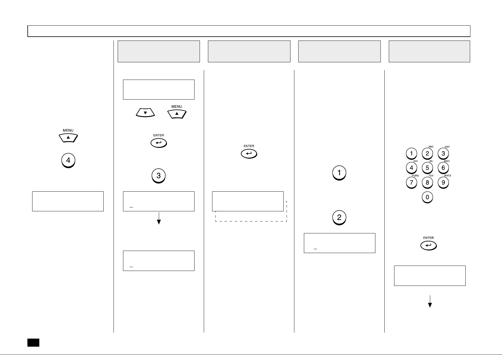
Terminal ID Setting
In compliance with FCC regulations (see page 1), this facsimile
places your company’s name,
facsimile telephone number and
date & time on top of all transmitted documents. This feature
enables remote parties to easily
identify your documents and
time of transmission.
To display the SETUP menu,
press:
+
INITIAL SETUP
1.LANGUAGE
Display the
1
TERMINAL ID Menu
Display
INITIAL SETUP
3.TERMINAL ID
Using or and
press:
or
NAME (40MAX)
[ ]
If the terminal ID is already set,
the current name is displayed
on the second row.
Enter the User ID
2
Enter your user ID (company
name) using the Numeric Keypad. You can use up to 40 characters.
For more information on selecting characters, see page 34,
Character Entry.
When your ID name is displayed
correctly on the LCD display,
press:
Your facsimile will prompt you
for your telephone number’s international code.
COUNTRY CODE
1.YES
2.NO
Select the
3
International Code
If you send documents overseas, adding your International
Code (country code) to your
stored ID name will enable the
remote party to identify the
country from which the document has been sent. The 1st
digit(s) following the “+” sign is
for the International Code.
If you send or receive documents to and from overseas,
press:
If all of your documents are sent
domestically, press:
FAX NUMBER (20MAX)
[+ ]
Enter Your
4
Telephone Number
If you selected YES in Step 3,
enter the International Code for
your country before entering
your area code and telephone
number.
Example: United States = 1
Then, enter the telephone num-
ber that has been connected to
the facsimile.
Check the LCD display to make
sure your telephone number
appears correctly, then press:
42
NAME (40MAX)
[DP80F/DP85F ]
The new name will be displayed
on the second row as it is entered.
The “+” is displayed when International Code is selected.
COMPLETED
Displayed for 2 seconds
Returns to display the SETUP
menu screen.
Page 45

Terminal ID Setting - continued
Select Another
5
SETUP Item, or ...
After completing this Configuration Setting, you may continue
to select other settings referring
to their associated pages for instructions, or press
to exit the Configuration Setting
mode and return to the Standby
Mode.
43
Page 46

Dial T ype Setting
There are two types of dialing
modes: DP [Dial Pulse (Rotary)]
and MF [Multi-Frequency (touch
tone)]. If your telephone emits
tones when you are dialing, this
usually indicates that you have
a MF type line and no adjustment is required. Otherwise, you
will have to select the appropriate setting.
To display the SETUP menu,
press:
+
INITIAL SETUP
1.LANGUAGE
Display the DIAL
1
TYPE Menu
Display
INITIAL SETUP
4.DIAL TYPE
Using or and
press:
or
DIAL TYPE
1.TONE
2.PULSE
Select Your Dial
2
Type
Select your dial line type.
(for Multi-Frequency type)
default
(for Dial Pulse type)
After selecting the dial type, the
following will be displayed.
DELETE ACCESS DIGIT
[ ]
Access digits are numbers
which are required by PBX systems to access the phone system “outside” the PBX. A common access digit is “9.”
Enter the Access
3
Digits
PBX Access Digits such as 9,
pause, and 1 need to be omitted
when using chain dialing.
If you will not be using the Chain
Dial feature, press
skip this step.
Otherwise, enter the Access
Digits to be deleted (max. 10
digits) using the Dial Keypad.
When the correct Access Digit is
displayed, press:
to
Select Another
4
SETUP Item, or ...
After completing this Configuration Setting, you may continue
to select other settings referring
to their associated pages for instructions, or press
to exit the Configuration Setting
mode and return to the Standby
Mode.
44
COMPLETED
Displayed for 2 seconds
Returns to display the SETUP
menu screen.
Page 47

- DEVICE CONFIGURATION
Configuration Summary
This facsimile has many user
adjustable settings.
Each of these configuration settings is discussed in detail
throughout the remainder of this
section.
Use the following procedures to
access one or more of these
configuration settings.
Enter the
1
Configuration Menu
Press
Screen displays.
MENU
1.FAX FEATURES
Press to enter DEFAULT
SETTINGS. The Default Set-
tings sub-menu displays.
DEFAULT SETTINGS
1.MACHINE SETTINGS
Press to enter MACHINE
SETTINGS. The Machine Set-
tings sub-menu will now be displayed.
. The initial Menu
Select the Desired Configuration Setting (01-11)
2
Press
Configuration Setting 01 through 11 from the list below. The detailed configuration procedure for each
setting is shown in parentheses after the configuration setting.
01. SPEAKER VOLUME - (Page 46) - Sets the Bell Ringer, Alarm Tone, Key Touch Tone and
Monitor volume (0-7) (5*) for the machine.
02. POWER SAVER - (Page 50) - Configures the machine’s Super Power Saver function for Auto-
matic/Manual* or Off operation and Printer Power Saver function for On or Off.
03. DEPARTMENT CODE - (Page 52) - Enables, Disables* and Configures up to 50 Department
Codes.
04. ACCOUNT CODE - (Page 56) - Enables or Disables* a 4-digit Account Code entry.
05. LINE MONITOR - (Page 57) - Enables or Disables* a Line Monitor function.
06. RECEIVE INTERVAL - (Page 58) - Sets an interval for the machine to wait (0 - 14 min.) after
making four consecutive dialings.
07. ECM - (Page 59) - Enables or Disables* an ECM function.
or until the desired Configuration Setting is displayed or enter the desired
MACHINE SETTINGS
01.SPEAKER VOLUME
02.POWER SAVER
03.DEPARTMENT CODE
04.ACCOUNT CODE
05.LINE MONITOR
06.RECEIVE INTERVAL
07.ECM
08.SORT COPY
09.REDIAL MODE
10.RECEPTION MODE
11.COPY REDUCTION
NOTE: Only 1 selection can be
displayed at one time.
08. SORT COPY - (Page 60) - Enables or Disables* a Sort Copy function.
09. REDIAL MODE - (Page 61) - Sets the number of redials (0-14) (5*) and redial interval (1min.-
15min.) (1*min.).
10. RECEPTION MODE - (Page 62) - Configures FAX*, FAX/TAD, TEL/FAX or Manual reception
modes.
11. COPY REDUCTION - (Page 64) - Configures the machine’s Copy Reduction function for Auto or
Off* operation.
NOTE: * indicates the factory default setting.
45
45
Page 48

Ringer V olume Adjustment
The bell ringer volume can be
adjusted using the following procedure.
Display the RINGER
1
VOLUME Menu
Press:
+
+
+
+
+
+
Enter the Desired
2
Volume Value
Enter the desired volume value
(1 to 8; 1 for maximum, 7 for
minimum, 8 for off).
or
Select the desired volume
value, using the following keys.
or
When the desired value is displayed, press:
Select Another
3
SETUP Item, or ...
After completing this Configuration Setting, you may continue
to select other volume settings
referring to their associated
pages for instructions, or press
to exit the Configuration Setting
mode and return to the Standby
Mode.
46
The current setting is displayed
on the bottom row.
RINGER VOLUME
5.>>>
COMPLETED
Displayed for 2 seconds
Returns to display the SETUP
menu screen.
Page 49

Alarm T one V olume Adjustment
The alarm tone volume can be
adjusted using the following procedure.
Display the ALARM
1
VOLUME Menu
Press:
+
+
+
+
+
+
Enter the Desired
2
Volume Value
Enter the desired volume value
(1 to 8; 1 for maximum, 7 for
minimum, 8 for off).
or
Select the desired volume
value, using the following keys.
or
When the desired value is displayed, press:
Select Another
3
SETUP Item, or ...
After completing this Configuration Setting, you may continue
to select other volume settings
referring to their associated
pages for instructions, or press
to exit the Configuration Setting
mode and return to the Standby
Mode.
The current setting is displayed
on the bottom row.
ALARM VOLUME
5.>>>
COMPLETED
Displayed for 2 seconds
Returns to display the SETUP
menu screen.
47
47
Page 50

Key T ouch T one V olume Adjustment
The key touch tone volume can
be adjusted using the following
procedure.
Display the KEY
1
TOUCH VOLUME
Menu
Press:
Enter the Desired
2
Volume Value
Enter the desired volume value
(1 to 8; 1 for maximum, 7 for
minimum, 8 for off).
+
+
+
or
+
+
+
Select the desired volume
value, using the following keys.
or
When the desired value is displayed, press:
Select Another
3
SETUP Item, or ...
After completing this Configuration Setting, you may continue
to select other volume settings
referring to their associated
pages for instructions, or press
to exit the Configuration Setting
mode and return to the Standby
Mode.
48
The current setting is displayed
on the bottom row.
KEY TOUCH VOLUME
5.>>>
COMPLETED
Displayed for 2 seconds
Returns to display the SETUP
menu screen.
Page 51

Monitor V olume Adjustment
The line monitor volume can be
adjusted using the following procedure.
Display the MONITOR
1
VOLUME Menu
Press:
+
+
+
+
+
+
Enter the Desired
2
Volume Value
Enter the desired volume value
(1 to 8; 1 for maximum, 7 for
minimum, 8 for off).
or
Select the desired volume
value, using the following keys.
or
When the desired value is displayed, press:
Select Another
3
SETUP Item, or ...
After completing this Configuration Setting, you may continue
to select other volume settings
referring to their associated
pages for instructions, or press
to exit the Configuration Setting
mode and return to the Standby
Mode.
The current setting is displayed
on the bottom row.
MONITOR VOLUME
5.>>>
COMPLETED
Displayed for 2 seconds
Returns to display the SETUP
menu screen.
49
49
Page 52

Power Saver Operation
This function allows you to minimize power consumption by
turning power off to portions of
the machine (as selected). If
the Power Saver function is ON,
a warm up period is needed before printing occurs. This facsimile has two Power Saver
modes, Super Power Saver and
Printer Power Saver.
Super Power Saver turns virtually all power off to minimize
power consumption. Select one
of three modes, Automatic,
Manual or OFF.
Printer Power Saver turns only
the fuser section off during the
time period selected.
NOTE:
When the machine is in the
Super Power Saver mode, it
will exit from the Super
Power Saver mode when
any of the following occurs.
- The machine receives a
facsimile,
- Option handset or external telephone handset is
lifted,
- Document is loaded into
the document tray,
Display the POWER
1
SAVER Menu
Press:
+
+
+
+
POWER SAVER
01.SUPER P.S.
02.PRINTER P.S.
Select the Power
2
Saver Mode
Select the desired Power Saver
Mode.
+
(to select Super Power
Saver mode)
SUPER P.S.
2.MANUAL
3.OFF
1.AUTOMATIC
Go to Step 3.
+
(to select Printer Power
Saver mode)
PRINTER P.S.
1.ON
2.OFF
Go to Step 5.
Select the Super
3
Power Saver Option
Select the desired Super Power
Saver Option.
(to select Automatic mode)
ENTER TIME
(1-60) [ 3]
Go to Step 4.
(to select Manual mode)
In manual mode, you can activate Super Power Saver using a
key on the Operation Panel.
Go to Step 7.
(to select OFF)
Go to Step 7.
Enter the Start Time
4
Period
Enter the time period (in minutes) for standby operation prior
to entering the Super Power
Saver mode.
ENTER TIME
(1-60) [ 3]
When the correct time period is
displayed, press:
COMPLETED
Displayed for 2 seconds
-
- PC has accessed the
machine.
50
is pressed, or
Returns to display the SETUP
menu screen.
Go to Step 7.
Page 53

Power Saver Operation - continued
Select the Printer Power Saver Function
5
Enable or Disable the Printer
Power Saver function.
(to set Printer Power Saver ON)
(to set Printer Power Saver OFF)
If “ON” is selected, the currently
set time period is displayed below. The time on the left is the
Printer Power Saver start time
(or time that the printer unit will
power down). The time on the
right is the Printer Power Saver
end time.
START/STOP TIME
[00:00-00:00]
(Example if the 24-hour format
option is selected in DATE &
TIME setting)
START/STOP TIME
[12:00AM-12:00AM]
(Example if the 12-hour format
option is selected in DATE &
TIME setting)
When “OFF” is selected, the
“COMPLETED” message is displayed as shown at the bottom
in Step 6. Returns to Step 1.
Enter the Start Time
6
and End Time
Move the cursor to the desired
position, using the following
keys.
or
Enter the time period.
Change the AM/PM designation
if selected by pressing the following keys.
or
When the correct time period is
displayed, press:
Select Another
7
SETUP Item, or ...
After completing this Configuration Setting, press
to exit the Configuration Setting
mode and return to the Standby
Mode.
COMPLETED
Displayed for 2 seconds
The display returns to Step 1.
51
51
Page 54

Department Code Setting
Department Code operation is
used to monitor the facsimiles
activity when shared between
multiple users or workgroups.
This feature is especially useful
when billing departments based
on machine usage.
When Department Code operation is enabled, access to the
facsimile is restricted to 50 valid
department code passwords.
Each department code will be
assigned a 5-digit department
code password. These passwords must be entered each
time a user wishes to send a
facsimile, make copy, print a department journal, etc.
There are two types of Department Codes, Master and Individual. The Master Code is used
as a supervisor level code to
add, delete and modify Individual Codes.
The Master Code is also used to
print the Department Code List
and Master Journals that contain all machine activity.
The Individual Codes are used
to gain an access to basic machine functions and operations.
These Department Codes can
be used to print Journals which
only show the activity under that
code.
Display the
1
DEPARTMENT CODE
Menu
Press:
+
+
+
+
SET DEPT. CODE
2.NO
1.YES
Enable/Disable the Department Code
2
Enable or Disable the Department Code function.
(for YES-Enable)
(for NO-Disable)
If “YES” is selected, the following Master Code Name Entry
screen is displayed.
NAME
[ ]
If “NO” is selected, “COMPLETED” will be displayed.
COMPLETED
Displayed for 2 seconds
Returns to the Standby mode.
If Department Code has ever
been set before, the following
screen is displayed.
To recover previously set Department Codes, press:
Go to Step 5.
To set a new Department code,
press:
Go to Step 3.
SET DEPT. CODE
1.RECOVER SETTING
2.NEW
Enter the Master
3
Department Name
Department Code NBR. 01 is
fixed as the Master Department
Code. Enter the Master Department Name. See page 36 if you
need help selecting characters.
When the name is correctly displayed on the LCD display,
press:
MASTER CODE
[ ]
52
Page 55

Department Code Setting - continued
Enter the Master
4
Department Code
Password
Enter a 5-digit Master Department Code Password using the
Dial Keypad. This password will
be required to gain supervisor
access to the machine.
Important: Record the password in a safe location so that if
it is lost or forgotten it can be
retrieved.
When the password is correctly
entered, press:
Enter the Individual
5
Department Code
Address
After entering the Master Department Code password, the
facsimile will prompt for an Individual Department Code address.
Select an Individual Department
Code address from 02 to 50.
After selecting the Individual Department Code address, press:
Enter the Individual
6
Department Code
Name
Department Codes NBR. 02
through 50 are used as Individual Department Codes. Enter
the Individual Department Code
name using the Dial keypad.
See page 36 if you need help
selecting characters.
When the name is correctly displayed on the LCD display,
press:
Enter the Department
7
Code Password
Enter a 5-digit Department
Code Password using the Dial
Keypad. This password will be
required to gain user/department access to the machine.
Important: Record this password in a safe location so that if
it is lost or forgotten it can be
retrieved.
When the password is correctly
entered, press:
Select Another
8
SETUP Item, or ...
If you want to continue entering
Department Codes, repeat
Steps 5 through 7.
After completing this Configuration Setting, you may continue
to select other settings referring
to their associated pages for instructions, or press:
to exit the Configuration Setting
mode and return to the Standby
Mode.
DEPT. NUMBER
(1-50) [ ]
NAME
[ ]
DEPT. CODE
[ ]
COMPLETED
Displayed for 2 seconds
DEPT. NUMBER
(1-50) [ ]
53
53
Page 56

Department Code Maintenance
The Department Code Maintenance is used to cancel or
change the Master or Individual
Department Code.
This procedure can only be performed by a supervisor who
possesses the Master Department Code Password. Enter this
password before proceeding.
Display the
1
DEPARTMENT
CODE Menu
Press:
Enable/Disable the
2
Department Code
Enable or Disable the Department Code function.
+
(for YES-Enable)
+
(for NO-Disable)
+
+
NOTE: Disabling Department
Codes will delete all
information related to
the Department Codes
stored.
If “YES” is selected, the following Master Code Menu is displayed.
Enter the Master or
3
Individual Department
Code Address
Select a Master or Individual
Department Code address from
1 to 50.
After selecting the Individual Department Code address, press:
Select the Desired
4
Option
Select the desired option.
Press:
To delete the previously displayed Department Code and
return to the Department Code
Address Entry menu in Step 4 of
Department Code Setting. (See
page 53.)
To change the previously displayed Department Code and
return to Step 5 of Department
Code Setting. (See page 53.)
54
SET DEPT. CODE
1.YES
2.NO
DEPT. NUMBER
(1-50) [ ]
DEPT. NUMBER 2
3.RETAIN
1.DELETE
2.MODIFY
To retain the previously displayed Department Code without modification and return to
the Department Code Address
Entry menu in Step 4 of Department Code Setting. (See page
53.)
Page 57

Department Code Maintenance - continued
Select Another
5
SETUP Item, or ...
If you wish to continue, repeat
Steps 2 and 3.
After completing this Configuration Setting, you may continue
to select other settings referring
to their associated pages for instructions, or press
to exit the Configuration Setting
mode and return to the Standby
Mode.
55
55
Page 58

Account Codes Setting
This feature provides valuable
Account Code tracking information for each facsimile transmission sent from the unit.
When a facsimile is transmitted,
the account code number will be
recorded on the Transmission
Journal.
Display the
1
ACCOUNT CODE
Menu
Press:
ACCOUNT CODE
2.OFF
1.ON
Select the Function
2
Select Another
3
SETUP Item, or ...
Enable or Disable Account
Codes.
+
Select ON to enable Account
+
+
+
Code prompting and printing on
the Transmission Journal.
Or, select OFF to disable Account Codes from being prompted and printed on the Transmission Journal.
COMPLETED
Displayed for 2 seconds
After completing this Configuration Setting, you may continue
to select other settings referring
to their associated pages for instructions, or press
to exit the Configuration Setting
mode and return to the Standby
Mode.
56
Returns to display the SETUP
menu screen.
Page 59

Line Monitor Default Setting
This function is used to set the
speaker ON in order to monitor
every transmission.
This function is mainly used to
confirm dialing and phone line
status.
Display the LINE
1
MONITOR Menu
Press:
Select the Line
2
Monitor Option
To turn ON the monitor speaker,
press:
+
To turn OFF the monitor
+
+
+
speaker, press:
Select Another
3
SETUP Item, or ...
After completing this Configuration Setting, you may continue
to select other settings referring
to their associated pages for instructions, or press
to exit the Configuration Setting
mode and return to the Standby
Mode.
LINE MONITOR
2.OFF
1.ALWAYS
COMPLETED
Displayed for 2 seconds
Returns to display the SETUP
menu screen.
57
Page 60

Receive Interval Setting Operation
This function insures there will
be a period of time set aside for
receiving incoming facsimiles
during periods of heavy out going transmission activity. After
every fourth consecutive transmission, this machine will wait 0
to 14 minutes to allow incoming
facsimiles to be received (default is 3 minutes).
Display the RECEIVE
1
INTERVAL Menu
Press:
+
+
+
+
Enter the Receive
2
Interval
Enter the interval value (0 to 14)
in minutes.
Then press:
Select Another
3
SETUP Item, or ...
After completing this Configuration Setting, you may continue
to select other settings referring
to their associated pages for instructions, or press
to exit the Configuration Setting
mode and return to the Standby
Mode.
58
INTERVAL TIME
(0-14) [ 3]
COMPLETED
Displayed for 2 seconds
Returns to display the SETUP
menu screen.
Page 61

ECM Default Setting
ECM (Error Correction Mode) is
an internationally-recognized error correction system. It enables
error free communications by
automatically re-sending any
portion of the document affected
by phone line noise or distortion.
NOTES:
• Default ECM setting is
ON.
• Both the sender and the
receiver must have the
ECM feature to perform
ECM communications.
• This setting cannot be
changed if a document is
stored in memory. Residual memory must be
100%.
Display the SET
1
ECM Menu
Press:
ECM
1.ON
2.OFF
Select the ECM
2
Option
Select the desired ECM option.
To turn ECM to ON, press:
+
+
+
+
To turn ECM to OFF, press:
COMPLETED
Displayed for 2 seconds
Returns to display the SETUP
menu screen.
Select Another
3
SETUP Item, or ...
After completing this Configuration Setting, you may continue
to select other settings referring
to their associated pages for instructions, or press
to exit the Configuration Setting
mode and return to the Standby
Mode.
59
Page 62

Sort Copy Setting
When copying documents, the SORT function may be selected.
This function will sort multiple page copies into sets of correct-order
pages.
This setting establishes the default for the Sort Copy function. Sort
copy may, also, be set manually at the time the copy operation is
performed.
Output Examples of Printed Copies
With SORT Function ON With SORT Function OFF
Page 3
Page 2
Page 1
Page 3
Page 2
Page 1
Page 3
Page 2
Page 1
NOTES:
• The pages are automatically sorted.
• Requires enough memory
for the entire multi-page
document. If there is not
enough memory (memory
overflow), the copying procedure will be canceled.
Page 2
Page 3
Page 3
Page 3
NOTES:
• Sorting is the responsibility
of the operator.
• Memory requirements are
limited to one page at a
time.
Page 1
Page 1
Page 1
Page 2
Page 2
Display the SORT
1
COPY Menu
Press:
SORT COPY
2.OFF
1.ON
Select the Desired
2
Option
Select the desired option.
To set SORT COPY to ON,
press:
+
+
+
+
To set SORT COPY to OFF,
press:
COMPLETED
Displayed for 2 seconds
Returns to display the SETUP
menu screen.
Select Another
3
SETUP Item, or ...
After completing this Configuration Setting, you may continue
to select other settings referring
to their associated pages for instructions, or press
to exit the Configuration Setting
mode and return to the Standby
Mode.
• Collation is slower than
non-collation because the
entire document must be
scanned into memory first,
then printing can occur.
60
Page 63

Setting Redial (Interval and Counter)
If the destination facsimile you
called is busy, your facsimile will
automatically redial the number
up to the number of attempts set
by this procedure. In addition,
your DP80F/DP85F will try to redial every 1 minute by default. If
desired, you may change these
redial settings.
Redial Interval
The Redial Interval sets the
length of time between redial attempts. The default redial interval is 1 minute. You may
change the interval from 1 to 15
minutes.
Redial Counter
The Redial Counter sets the
number of redial attempts. The
default setting is 5. You may
change the number of redials
from 0 to 14 attempts.
Display the REDIAL
1
MODE Menu
Press:
+
+
+
+
Enter the Redial
2
Interval
Enter the interval value (1 to 15)
in minutes.
Then press:
The following screen is displayed.
Enter the Redial
3
Counter
Enter the redial counter value (0
to 14).
Then press:
The following screen is displayed.
Select Another
4
SETUP Item, or ...
After completing this Configuration Setting, you may continue
to select other settings referring
to their associated pages for instructions, or press
to exit the Configuration Setting
mode and return to the Standby
Mode.
(1-15) [ 1]
REDIAL COUNT
(0-14) [ 5]
COMPLETEDINTERVAL (MINUTES)
Displayed for 2 seconds
Returns to display the SETUP
menu screen.
61
Page 64

Reception Mode Default Setting
The DP80F/DP85F have four
reception modes and the receiving function differs according to
the selected mode.
• AUTO RECEIVE
• TEL/FAX
• FAX/TAD
• MANUAL RECEIVE
AUTO RECEIVE (FAX):
If you use the unit as a facsimile
most of the time, you should select this mode. When the unit receives a call, the unit enters the
automatic fax reception mode
after the selected ring delay.
FAX/TAD
This mode is used together with
a TAD (telephone answering device/machine).
This mode allows you to receive
voice messages and facsimile
receptions even when no one is
present in the office.
Switching between the voice
message recording and facsimile receiving is performed automatically.
TEL/FAX:
This mode is used when the line
is used for both facsimile and
telephone functions.
The facsimile automatically determines whether an incoming
call is for facsimile or telephone.
When the call is for telephone,
the ringer will ring according to
the value set for the call time.
When the call is for facsimile,
the machine will automatically
start receiving the document.
MANUAL:
This mode is used when the facsimile is connected to a line that
is primarily used as a (voice)
telephone line.
Upon receiving a ring-in signal,
pick up the handset to talk with
the remote party before starting
a facsimile communication.
NOTE:
Manual Reception must be
initiated by an operator. No
facsimile receiving operations will be possible if no
one is present to initiate the
reception.
Display the Reception
1
Mode Menu
Press:
+
+
+
+
RECEPTION MODE
1.FAX
2.FAX/TAD
3.TEL/FAX
4.MANUAL
Select the Desired Reception Mode
2
Select the desired Reception
Mode.
(for AUTO RECEIVE)
If AUTO RECEIVE is selected,
the following will be displayed.
RINGS TO ANSWER
(1-10) [ 2]
Go to Step 3.
(for FAX/TAD RECEIVE)
FAX/TAD TIMER
(0-99) [45]
Go to Step 4.
Go to Step 5.
If MANUAL RECEIVE is selected, the following will be displayed for 2 seconds (continue
to Step 6).
(for TEL/FAX RECEIVE)
TEL/FAX RINGS
(1-15) [ 6]
(for MANUAL RECEIVE)
COMPLETED
62
Page 65

Reception Mode Default Setting - continued
Enter the FAX Ring
3
Delay
Enter the desired number of
rings (1 to 10) before the facsimile will answer the incoming
call in Auto Receive mode.
When the desired ring count is
displayed on the LCD, press:
COMPLETED
Enter the FAX
4
Monitor Time
Enter the desired Fax Monitor
Time (00 to 99). During this period, the facsimile will monitor
for the automatic fax CNG signal. If detected, the unit will
switch to fax reception when set
for FAX/TAD mode.
When the desired Fax monitor
time is displayed on the LCD,
press:
Enter the Pseudo
5
Ring Delay
Enter the desired number of
pseudo rings (1 to 15) before
switching to facsimile reception
in TEL/FAX mode.
When the desired ring count is
displayed on the LCD, press:
COMPLETED
Select Another
6
SETUP Item, or ...
After completing this Configuration Setting, you may continue
to select other settings referring
to their associated pages for instructions, or press
to exit the Configuration Setting
mode and return to the Standby
Mode.
Displayed for 2 seconds
Returns to display the SETUP
menu screen.
Go to Step 6.
COMPLETED
Displayed for 2 seconds
Returns to display the SETUP
menu screen.
Go to Step 6.
Displayed for 2 seconds
Returns to display the SETUP
menu screen.
Go to Step 6.
63
Page 66

Copy Reduction Setting
This function allows automatic
reduction of the recording image when making copies. The
default setting is OFF.
NOTES:
• If this function is enabled, documents longer
than the effective printable area (see page 86)
will be reduced by 95,
90, 86, 83, 80 or 73%
depending on the document length.
• If this function is disabled, documents more
than 10 mm longer than
the effective printable
area will be split onto
two pages. No image will
be discarded.
The excess portion of a
document that is less
than 10 mm longer than
the effective printable
area will be discarded.
Contact your authorized
TOSHIBA service representative for additional information.
Display the COPY
1
REDUCTION Menu
Press:
+
+
+
+
COPY REDUCTION
2.OFF
1.AUTO
Select the Copy
2
Reduction
To set Copy Reduction to
AUTO, press:
To set Copy Reduction to OFF,
press:
COMPLETED
Displayed for 2 seconds
Returns to display the SETUP
menu screen.
Select Another
3
SETUP Item, or ...
After completing this Configuration Setting, you may continue
to select other settings referring
to their associated pages for instructions, or press
to exit the Configuration Setting
mode and return to the Standby
Mode.
64
Page 67

BASIC FUNCTIONS - AUTOMATIC TELEPHONE DIALING
Abbreviated Dialer Registration
Once registered, 38 One Touch
and 100 (DP80F)/150 (DP85F)
Abbreviated Dial Numbers will allow you to send documents or
make telephone calls to 138
(DP80F)/183 (DP85F) frequently
called numbers without manually
dialing the entire number.
• Abbreviated Dial Numbers
This machine can store up to
100 (DP80F)/150 (DP85F)
16-digit facsimile numbers
and associated 20-character
location ID names. This information is stored into Abbreviated Dial Numbers labeled
from 001 to 999.
• One Touch Numbers
See page 71.
• Alternate Numbers
If one of the primary facsimile
numbers is busy, and a 2nd
facsimile is located at that
same remote location, the
2nd facsimile’s telephone
number can be programmed
as an Alternate Number.
IMPORTANT:
The total number of available
locations will vary depending
upon the amount of information stored in each location.
Up to 128 digits can be programmed into a One Touch
or Abbreviated number.
Display the TEL
1
LIST ENTRY Menu
Press:
+
TEL LIST ENTRY
1.ABB. NUMBERS
2.ONE TOUCH KEYS
3.GROUP NUMBERS
Display the ABB.
2
NUMBERS Menu
To select “ABB. NUMBERS,”
press:
ABB. NUMBER ENTRY
(1-999) [ ]
Enter an ABB. Dial
3
Number
Enter an Abbreviated Dial Number from 1 to 999.
Make sure the 3-digit number
(001 to 999) appears correctly,
then press:
NOTE:
Any leading zero (0) can be
omitted from the Abbreviated
Dial Number.
If the ABB. Dial Number you entered has not been previously
registered, the screen below will
be displayed.
FAX NUMBER (128MAX)
[ ]
Skip to Step 6.
If the ABB. Dial Number you en-
tered has been previously registered, continue to the next step.
When a Preset ABB.
4
Dial Number is Active
If the selected Abbreviated Dial
Number has been previously
registered, the following information will be displayed on the
LCD display.
ALREADY ASSIGNED
Displayed for 2 seconds
ABB. NUMBER ENTRY
3.RETAIN
1.DELETE
2.MODIFY
65
Page 68

Abbreviated Dialer Registration - continued
Change the ABB. Information
5
You can delete, modify, or retain
Abbreviated Dial Numbers registered in this facsimile.
• DELETE
Deletes the information
stored in the selected Abbreviated Dial Number. It will
also remove the number
from all associated Group Dialing Directories.
• MODIFY
Allows you to change the remote facsimile number and/
or associated Location ID
name. This selection is recommended if the location is
used in Group Dialing Directories.
• RETAIN
Retains the selected Abbreviated Dial Number information without modification.
5a
Delete the ABB. Dial
Information
To delete the contents stored in
the Abbreviated Dial Number,
press:
(to DELETE)
SPEED DIAL NBR 001
ARE YOU SURE ?
Then press:
Return to Step 3.
5b
Modify the ABB. Dial
Information
To change the number or Location ID (remote facsimile name)
currently assigned to an existing Abbreviated Dial Number,
press:
(to MODIFY)
The facsimile number currently
assigned is displayed on the
bottom row.
FAX NUMBER (128MAX)
[XXXXX ]
Skip to Step 6.
5c
Retain the Current
ABB. Dial Information
If you do not wish to change the
Abbreviated Dial Number information, press:
(to RETAIN)
Return to Step 3 to select a different Abbreviated Dial Number
or press
Standby Mode.
to return to the
Enter the Telephone
6
Number
Enter the telephone number you
want to store (up to 128 digits).
NOTE:
If your facsimile is connected
to a PBX system, you may
need to enter an access digit
(9) and a pause so the system will connect you to an
outside line. In such cases,
press
ond pause. This pause may
be repeated if necessary and
may be entered anywhere
between digits. A pause entry is indicated as a hyphen
“–” on the LCD display.
to enter a 3-sec-
66
Page 69

Abbreviated Dialer Registration - continued
Enter the Telephone
6
Number - continued
The telephone number is displayed on the bottom row of the
LCD display as you enter it.
Confirm that the number is correct.
FAX NUMBER (MAX128)
[9583359 ]
Then press:
ALT NUMBER (128 MAX)
[ ]
Enter an Alternate
7
Number (Optional)
Alternate Numbers are optional.
If the remote location does not
have two or more facsimile units
in the same area, you can leave
this entry blank. (See page 65
for more information.)
Enter the Alternate Facsimile
Number.
Then press:
NAME (20 MAX)
[ ]
Enter the Location
8
ID Name
Enter the Location ID name of
the remote party to be assigned
to the current Abbreviated Dial
Number.
See page 36 for more information on Character Entry.
When the name is displayed
correctly on the LCD display,
press:
FAX OPTIONS
2.NO
1.YES
Select Communication Options
9
(Advanced Setup)
This setting will allow you to
specify one or more of the following Communication Options
for the Abbreviated Dial Number
you are registering.
Delayed Communication
Default=off
Select to program a transmission start time.
Transmission Report
Default=off
Enables or disables the
printing of a TX Report.
Line Monitor
Default=off
Enables or disables the line
monitor speaker during dialing.
Fax Speed
Default=off
Selects a lower modem
speed for poor communication links.
Sub Address
Default=none
Specifies a Sub Address for
the Abbreviated Dial Number
being registered. The remote
unit must support Sub-Address capabilities.
9a
Select the
Communication
Option
To skip the Communication Options, press:
Go to next step.
To select Communication Op-
tions, press:
When “1.YES” is selected, the
FAX OPTIONS screen appears.
Follow the next steps for each
item selection.
FAX OPTIONS
1.DONE
2.DELAYED COMM.
3.TX REPORT
4.LINE MONITOR
5.FAX SPEED
6.SUBADDRESS
These items are outside
the LCD frame. To view
them, use the
scroll key.
67
Page 70

Abbreviated Dialer Registration - continued
Select Communication Options (Advanced Setup) - continued
9
9b
Done with Option
Setup
If you have completed the desired Communication Options
setting for this Abbreviated Dial
Number, select DONE by pressing:
PRESS ONE TOUCH
OR ENTER
Skip to Step 10.
9c
Delayed Communications
To designate a specific time at
which operations using this Abbreviated Dial Number will be
dialed, press:
DELAYED COMM.
[HH:MMAM]
(12 hour format)
DELAYED COMM.
[HH:MM]
(24 hour format)
Enter the desired transmission
start time in either the 12-hour
or 24-hour format depending on
the machine setup. (example:
11:30PM in the 12-hour format).
For the 12 hour format, select
DELAYED COMM.
[11:30PM] ↑↓
AM/PM using the or
.
Then press:
9d
Transmission Report
To request a Transmission Report automatically after sending
documents using this Abbreviated Dial Number, select:
TX REPORT
2.OFF
1.ON
To enable a TX Report, press:
To disable a TX Report, press:
9e
Line Monitor Speaker
To enable/disable the
facsimile’s Line Monitor
Speaker when dialing this Abbreviated Dial Number, press:
LINE MONITOR
2.OFF
1.ON
To enable the monitor speaker,
press:
To disable the monitor speaker,
press:
68
The display returns to the first
screen in Step 9. Select the
next Option.
The display returns to the first
screen in Step 9. Select the next
Option.
The display returns to the first
screen in Step 9. Select the next
Option.
Page 71
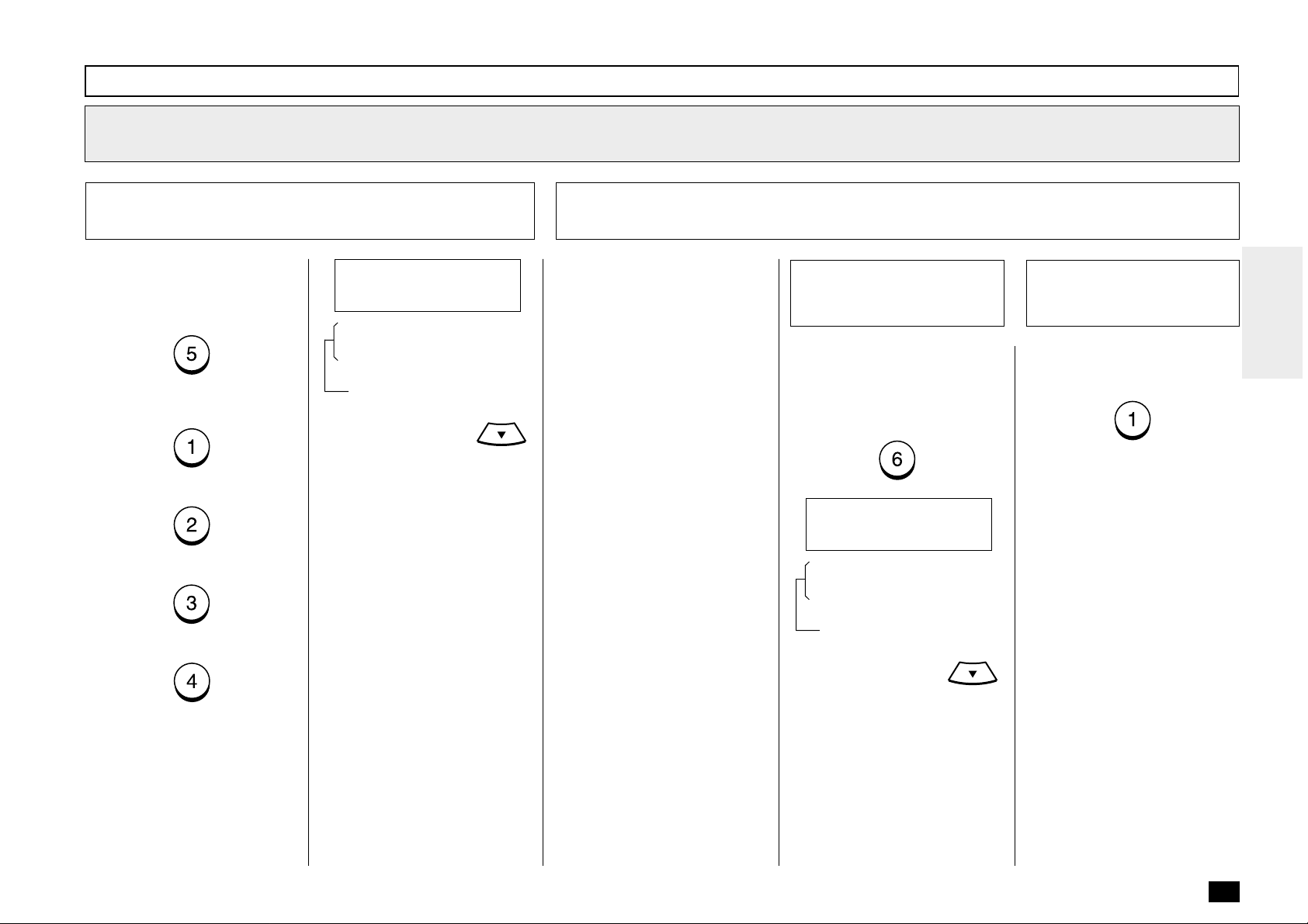
Abbreviated Dialer Registration - continued
Select Communication Options - continued
9
9f
Fax Speed
To transmit documents using
this Abbreviated Dial Number at
a lower speed to compensate
for poor line conditions, press:
To select the FASTEST POSSIBLE, press:
To select 14400BPS, press:
To select 9600BPS, press:
To select 4800BPS, press:
FAX SPEED
1.FASTEST POSSIBLE
2.14400BPS
3.9600BPS
4.4800BPS
These items are outside
the LCD frame. To view
them, use the
scroll key.
The display returns to the first
screen in Step 9. Select the next
Option.
9g
Sub-Address Communication
Sub-Address Communications
allow a variety of specialized
facsimile communications.
SUB
Sub-Address Transmission
Allows documents to be routed
through remote LAN-Facsimile
devices to specific users’ workstations.
Allows documents to be transmitted to specific Mailboxes in
remote facsimiles.
SEP
Selective Polling
Allows documents to be retrieved from specific Mailboxes
in remote facsimiles.
PWD
Password
Allows secure communications
to SUB and from SEP compatible devices.
IMPORTANT:
If you designate an incorrect
sub-address, the communication will result in an error. If you
designate an unnecessary subaddress, the communication will
result in error.
9g-1
If the remote party assigned to
the Abbreviated Dial Number requires or provides a Sub Address to route or retrieve messages, press:
Select the SubAddress Options
SUBADDRESS
1.DONE
2.SUBADDRESS SUB
3.SUBADDRESS SEP
4.SUBADDRESS PWD
These items are outside
the LCD frame. To view
them, use the
scroll key.
9g-2
To complete Sub Address entry
or skip this option, press:
The display returns to the first
screen in Step 9.
Complete the
Sub-Address
Options Setup
69
Page 72

Abbreviated Dialer Registration - continued
Select Communication Options - continued
9
9g
Sub-Address Communication - continued
9g-3
To enter a SUB type Sub Address, press:
Enter the required number (max.
20 digits), then press:
Select a SUB
Sub-Address
Communication
SUB (20MAX)
[ ]
9g-4
To enter a SEP type Sub Address, press:
Enter the required number (max.
20 digits), then press:
Select a SEP
Sub-Address
Communication
SEP (20MAX)
[ ]
9g-5
To enter a PWD type Sub Address, press:
Enter the required number (max.
20 digits), then press:
Select a PWD
Sub-Address
Communication
PWD (20MAX)
[ ]
10
Assign the Abbreviated Dial Number to a One
Touch Key
10a
Assign the
One Touch Key
To assign this Abbreviated Dial
Number to a One Touch Key,
press the desired One Touch
Key (Example: One Touch Key
01).
COMPLETED
After 2 seconds:
Returns to Step 2.
Press
Operation mode and return to
the Standby Mode.
to exit the Menu
10b
Use a Preassigned
One Touch Key
If the desired One Touch Key
has been previously linked to
another Abbreviated Dial Number or preset with a separate
One Touch number, one of the
following screens will be displayed.
ALREADY ASSIGNED
After 2 seconds:
ONE TOUCH NBR
1.DELETE
2.RETAIN
To DELETE the existing link or
One Touch assignment and return to Step 10a, press:
Returns to Step 9g-1.
70
Returns to Step 9g-1.
Returns to Step 9g-1.
To RETAIN the existing link or
One Touch assignment and return to Step 10a, press:
PRESS ONE TOUCH
OR ENTER
Page 73

One Touch Dialer Registration
This facsimile provides a total of
38 One Touch Dial keys.
• Alternate Numbers
If one of the primary facsimile numbers is busy, and
a 2nd facsimile is located at
that same remote location,
the 2nd facsimile’s telephone number can be programmed as an Alternate
Number.
Display the TEL
1
LIST ENTRY Menu
Press:
TEL LIST ENTRY
1.ABB. NUMBERS
2.ONE TOUCH KEYS
3.GROUP NUMBERS
Display the ONE
2
TOUCH KEYS Menu
To select “ONE TOUCH KEYS”,
press:
+
PRESS ONE TOUCH
Select a One Touch
3
Location
Press the desired One Touch
key.
Example: One Touch key 03
If the One Touch key has not
been previously used and the
following menu is displayed,
skip to Step 6.
FAX NUMBER (128MAX)
[ ]
When a Preset One
4
Touch is Active
If the pressed One Touch key
has already been registered
with a telephone number, the
following information appears on
the LCD display.
ALREADY ASSIGNED
After 2 seconds:
ONE TOUCH NBR
3.RETAIN
1.DELETE
2.MODIFY
71
Page 74

One Touch Dialer Registration - continued
Change One Touch Information
5
You can delete, modify or retain
the One Touch key once registered into the facsimile.
• DELETE
Deletes the information
stored in the selected One
Touch key. It will also remove the number from all
associated Group Dialing Directories.
• MODIFY
Allows you to change the remote facsimile number and/
or associated Location ID
name. This selection is recommended if the location is
used in Group Dialing Directories.
• RETAIN
Retains the selected One
Touch key information without modification.
5a
Delete the One Touch
Assignment
To delete the One Touch key
assignment, press:
(to DELETE)
ONE TOUCH NBR 03
ARE YOU SURE ?
Then press:
Return to Step 3.
5b
Modify the One Touch
Assignment
To change the number or Location ID (remote facsimile name)
currently assigned to an existing
One Touch key press:
(to MODIFY)
The facsimile number currently
assigned is displayed on the
bottom row.
FAX NUMBER (128MAX)
[XXXXX ]
Return to Step 6.
5c
Retain the One Touch
Assignment
To retain the previous One
Touch key assignment, press:
(to RETAIN)
Return to Step 3 to select a different One Touch key or press
to return to the Standby
Mode.
Enter the Telephone
6
Number
Enter the telephone number you
want to store (up to 128 digits).
NOTE:
If your facsimile is connected
to a PBX system, you may
need to enter an access digit
(9) and a pause so the system will connect you to an
outside line. In such cases,
press
ond pause. This pause may
be repeated if necessary and
may be entered anywhere
between digits. A pause entry is indicated as a hyphen
“–” on the LCD display.
to enter a 3-sec-
72
Page 75

One Touch Dialer Registration - continued
Enter the Telephone
6
Number - continued
The telephone number is displayed on the bottom row of the
LCD display as you enter it.
Confirm that the number is correct.
FAX NUMBER (MAX128)
[9583359 ]
Then press:
ALT NUMBER (128 MAX)
[ ]
Enter an Alternate
7
Number (Optional)
Alternate Numbers are optional.
If the remote location does not
have two or more facsimile units
in the same area, you can leave
this entry blank. (See page 71
for more information.)
Enter the Alternate Facsimile
Number.
Then press:
NAME (20 MAX)
[ ]
Enter the Location
8
ID Name
Enter the Location ID name of
the remote party to be assigned
to the current One Touch Dial
Number.
See page 36 for more information on Character Entry.
When the name is displayed
correctly on the LCD display,
press:
FAX OPTIONS
2.NO
1.YES
Select Communication Options
9
(Advanced Setup)
This setting will allow you to
specify one or more of the following Communication Options
for the One Touch Number you
are registering.
Delayed Communication
Default=off
Select to program a transmission start time.
Transmission Report
Default=off
Enables or disables the
printing of a TX Report.
Line Monitor
Default=off
Enables or disables the line
monitor speaker during dialing.
Fax Speed
Default=off
Selects a lower modem
speed for poor communication links.
Sub Address
Default=none
Specifies a Sub Address for
the Abbreviated Dial Number
being registered. The remote
unit must support Sub-Address capabilities.
9a
Select the
Communication
Option
To skip the Communication Options, press:
Return to Step 3.
To select Communication Op-
tions, press:
When “1.YES” is selected, the
FAX OPTIONS screen appears.
Follow the next steps for each
item selection.
FAX OPTIONS
1.DONE
2.DELAYED COMM.
3.TX REPORT
4.LINE MONITOR
5.FAX SPEED
6.SUBADDRESS
These items are outside
the LCD frame. To view
them, use the
scroll key.
73
Page 76

One Touch Dialer Registration - continued
Select Communication Options (Advanced Setup) - continued
9
9b
Done with Option
Setup
If you have completed the desired Communication Options
setting for this One Touch Dial
Number, select DONE by pressing:
PRESS ONE TOUCH
OR ENTER
Skip to Step 10.
9c
Delayed Communications
To designate a specific time at
which operations using this
One Touch Dial Number will be
dialed, press:
DELAYED COMM.
[HH:MMAM]
(12-hour format)
DELAYED COMM.
[HH:MM]
(24-hour format)
Enter the desired transmission
start time in either the 12-hour
or 24-hour format depending on
the machine setup. (example:
11:30PM in the 12-hour format).
For the 12 hour format, select
DELAYED COMM.
[11:30PM] ↑↓
AM/PM using the or
.
Then press:
9d
Transmission Report
To request a Transmission Report automatically after sending
documents using this One
Touch Dial Number, select:
TX REPORT
2.OFF
1.ON
To enable a TX Report, press:
To disable a TX Report, press:
9e
Line Monitor Speaker
To enable/disable the facsimile’s Line Monitor Speaker when
dialing this One Touch Dial
Number, press:
LINE MONITOR
2.OFF
1.ON
To enable the monitor speaker,
press:
To disable the monitor speaker,
press:
74
The display returns to the first
screen in Step 9. Select the
next Option.
The display returns to the first
screen in Step 9. Select the next
Option.
The display returns to the first
screen in Step 9. Select the next
Option.
Page 77

One Touch Dialer Registration - continued
Select Communication Options - continued
9
9f
Fax Speed
To transmit documents using
this One Touch Dial Number at
a lower speed to compensate
for poor line conditions, press:
To select the FASTEST POSSIBLE, press:
To select 14400BPS, press:
To select 9600BPS, press:
To select 4800BPS, press:
FAX SPEED
1.FASTEST POSSIBLE
2.14400BPS
3.9600BPS
4.4800BPS
These items are outside
the LCD frame. To view
them, use the
scroll key.
The display returns to the first
screen in Step 9. Select the next
Option.
9g
Sub-Address Communication
Sub-Address Communications
allow a variety of specialized
facsimile communications.
SUB
Sub-Address Transmission
Allows documents to be routed
through remote LAN-Facsimile
devices to specific users’ workstations.
Allows documents to be transmitted to specific Mailboxes in
remote facsimiles.
SEP
Selective Polling
Allows documents to be retrieved from specific Mailboxes
in remote facsimiles.
PWD
Password
Allows secure communications
to SUB and from SEP compatible devices.
IMPORTANT:
If you designate an incorrect
sub-address, the communication will result in an error. If you
designate an unnecessary subaddress, the communication will
result in error.
9g-1
If the remote party assigned to
the One Touch Dial Number requires or provides a Sub Address to route or retrieve messages, press:
Select the Sub
Address Options
SUBADDRESS
1.DONE
2.SUBADDRESS SUB
3.SUBADDRESS SEP
4.SUBADDRESS PWD
These items are outside
the LCD frame. To view
them, use the
scroll key.
9g-2
To complete Sub Address entry
or skip this option, press:
The display returns to the first
screen in Step 9.
Complete the
Sub-Address
Options Setup
75
Page 78

One Touch Dialer Registration - continued
Select Communication Options - continued
9
9g
Sub-Address Communication - continued
9g-3
To enter a SUB type Sub Address, press:
Enter the required number (max.
20 digits), then press:
Returns to Step 9g-1.
Select a SUB
Sub-Address
Communication
SUB (20MAX)
[ ]
9g-4
To enter a SEP type Sub Address, press:
Enter the required number (max.
20 digits), then press:
Returns to Step 9g-1.
Select a SEP
Sub-Address
Communication
SEP (20MAX)
[ ]
9g-5
To enter a PWD type Sub Address, press:
Enter the required number (max.
20 digits), then press:
Returns to Step 9g-1.
Select a PWD
Sub-Address
Communication
PWD (20MAX)
[ ]
76
Page 79

Group Number Registration
You can send a document to
multiple remote parties in a
single operation. This is referred
to as Group Dialing or Multi-address Transmission.
It is useful to preset addresses,
to which Multi-address Transmissions are often performed, in
a group. To make a Multi-address Transmission easier, you
can assign such a group to a
One Touch key.
The preset groups can also be
used as groups for Multi-polling
Receptions.
You can register up to 25
(DP80F)/50(DF85F) Broadcast
Groups using any combination
of Group Numbers from 1 to
1999 (no duplications allowed).
You may also assign each
group an optional name of up
to 20 characters.
Each group can contain any
combination of the 100
(DP80F)/150 (DP85F) Abbreviated and/or 38 One Touch dial
locations and can be assigned
to a One Touch key.
Display the TEL
1
LIST ENTRY Menu
Press:
TEL LIST ENTRY
1.ABB. NUMBERS
2.ONE TOUCH KEYS
3.GROUP NUMBERS
Display the GROUP
2
Enter a Group Number
3
NUMBERS Menu
To select “GROUP NUMBERS,”
press:
+
GROUP NUMBER
(1-1999) [ ]
Enter a Group Number (1 to
1999).
Example: 1
GROUP NUMBER
(1-1999) [ 1]
Then press:
NAME (20 MAX)
[ ]
The display changes to the following for character entry (go to
Step 5).
If the number entered is already
registered as a Group Number,
you will receive an LCD prompt
like the one below.
ALREADY ASSIGNED
Displayed for 2 seconds
GROUP NUMBER
3.RETAIN
1.DELETE
2.MODIFY
To select “1.DELETE,” go to
Step 4a.
To select “2.MODIFY,” go to
Step 4b.
To select “3.RETAIN,” go to
Step 4c.
77
Page 80

Group Number Registration - continued
4a
Cancel the Existing
Group
To delete the existing Group,
press:
(to DELETE)
GROUP NUMBER 0001
ARE YOU SURE ?
Then press:
Return to Step 3.
4b
Modify the Existing
Group
To change the existing Group,
press:
(to MODIFY)
NAME
[COLORADO GRP]
The current Group Name is displayed.
Go to Step 5.
4c
Retain the Existing
Group
To retain the existing Group,
press:
(to RETAIN)
Return to Step 3 to select a different Group Dial Number or
press
Standby Mode.
to return to the
Enter the Group
5
Name
Enter the Group Name (with up
to 20 characters) associated
with the Group Number.
See page 36 for more information on Character Entry.
(When no name is entered in
this step, no name will be given
to the Group Number.)
When the name is displayed
correctly on the LCD display,
press:
ENTER ABB. NUMBER
OR ONE TOUCH
Enter a Remote
6
Station
Enter the addresses of the remote stations to be preset in
the group.
If a remote station is assigned
to a One Touch key, press the
One Touch key.
If a remote station is assigned
to an Abbreviated Dial Number,
enter the number then press
.
Example:
Abbreviated Dial Number
118 (preset as DENVER
OFFICE):
+
78
+
+
GROUP NUMBER 0001
SPEED DIAL NBR 118
After 2 seconds:
PRESS OT OR ABB.
OR ENTER
Page 81

Group Number Registration - continued
Enter a Remote
6
Station - continued
Repeat this step until all of the
required remote station addresses are entered. Then go to
Step 8.
NOTE:
• When the entered Abbreviated Dial Number or One
Touch key has not been preregistered with a facsimile
number, the display shows
the message “NUMBER
NOT LISTED.” Then returns
to Step 5.
• When the entered Abbreviated Dial Number or One
Touch key is already assigned in this group, the display shows the screens below.
ALREADY ASSIGNED
7a
Cancel the Group
Number Setting
To delete the existing remote
station from this group, press:
(to DELETE)
SPEED DIAL NBR 118
ARE YOU SURE ?
Press:
DELETED
Return to Step 6.
7b
Retain the Group
Number Setting
To retain this remote station in
this group, press:
(to RETAIN)
PRESS OT OR ABB.
OR ENTER
Return to Step 6.
Complete Group
8
Station Entries
When all the stations necessary
for this group are entered in
Step 6, press:
PRESS ONE TOUCH
OR ENTER
Assign a One Touch
9
Key
To assign this group to a One
Touch key, press the desired
One Touch key.
Example: One Touch key 20.
+
COMPLETED
After 2 seconds:
GROUP NUMBER
(1-1999) [ ]
Returns to Step 3.
After 2 seconds:
ALREADY ASSIGNED
2.RETAIN
1.DELETE
Go to Step 7a or Step 7b.
79
Page 82

Group Number Registration - continued
Assign a One Touch Key - continued
9
To skip assigning this group to a
One Touch key, press:
COMPLETED
Return to Step 3.
Press
Group Setting operation and re-
turn to the Standby Mode.
to complete the
If the selected One Touch key
is already linked to or registered
with data, the following is displayed.
ALREADY ASSIGNED
Displayed for 2 seconds
ONE TOUCH NBR
2.RETAIN
1.DELETE
To select “1.DELETE” (to delete
the existing link or preset data of
this One Touch key), press:
Returns to Step 9.
80
To RETAIN, press:
Returns to Step 9.
Page 83

- TRANSMIT CONFIGURATION
Document Specifications
The following table shows the specifications for original documents that can be used
with this facsimile.
Single Sheet Multiple Sheets
Max.
Document
Size
Min.
Effective Scanning
Width
Max. Capacity of
Document Tray
Thickness of
Document
NOTES:
• Operator assistance may be required for pages longer than 356 mm (14.02
inches).
• For multiple sheets, the documents must be the same size and paper type.
• A small border region of each document is not imaged when each document is
scanned. The effective scanning area is as shown in the figure below.
0.06 to 0.15 mm
[0.003 to 0.006 in.]
216 mm (W) x 1000 mm (L)
[8.5 in. (W) x 39.37 in. (L)]
148 mm (W) x 100 mm (L)
[5.83 in. (W) x 3.94 in. (L)]
214 mm
[8.43 in.]
Up to 15 sheets (Legal Size)
Up to 30 sheets (Letter Size)
0.065 to 0.1 mm
[0.003 to 0.004 in.]
Uncoated on both sidesType of Paper
Caution:
If the documents are any of the following, they should be copied to plain paper
before transmitting.
• Torn, wrinkled, or damp pages
• Folded pages or pages with holes
• Transparent pages or pages with a smooth, shiny finish
• Cloth or metal sheets
When using originals with the following specifications, use a carrier sheet to avoid
document jams or misfeeds. When using carrier sheets, only one sheet can be
sent at a time.
• Smaller than minimum size.
• With thickness less than 0.05 mm.
To use a carrier sheet, lift the clear cover, place a single document sheet face-up
on the paper sheet. Purchase carrier sheets from your TOSHIBA facsimile dealer
or use a transparency with a paper backing attached at the lead edge.
Letter/Legal Size
216 mm (8.5 inches)
2.5 mm (0.1 inches)
Effective
Scanning
Area
2.5 mm (0.1 inches)
214 mm (8.43 inches)
81
Page 84

Document Loading
Remove Attached
1
Items
46
80
Remove any staples, paper
clips, or other items from your
document before feeding it into
the facsimile.
When scanning Legal-size documents, extend the Document
Support Extension and Document Exit Tray Extension.
Place Document Pages on the Document
2
Support
About 45°
Document Face Side
47 48
Up to 30 sheets (Letter-size)
can be loaded and sent at a
time.
Stagger the leading edges of
the sheets slightly and insert
them into the document feeder.
Adjust the Document Guides to
fit the width of the document.
Load the document face down
on the Document Support. The
first page of your document
should be at the bottom of the
Document Support.
Gently insert the leading edge of
the paper into the facsimile as
shown. The facsimile waits 2
seconds, then pulls the document into the scanning area and
stops.
When a Carrier Sheet is used,
documents must be sent one
page at a time (manually fed).
When the document sheet is
longer the Document Support,
assist it with your hand to insure
proper feeding.
Adjust the Settings
3
After the facsimile pulls the
document into the scan position
slightly and stops, you may
change the resolution and contrast settings. (It may also be
changed before or during the
document loading.)
To cancel a document already
set and pulled in, press:
If your document is extremely
dark or light, or if it contains
photographs, you may wish to
adjust the contrast and resolution settings. See the following
pages.
82
Page 85

Scan Resolution Setting
The scan resolution can be set
to one of the following five
modes based on the type of image you are scanning.
The scan resolution is normally
set to the default setting. When
you change the resolution, the
facsimile will return to the default setting after each transaction. To change the default resolution setting, see page 85.
Press until the required resolution mode is
indicated by the appropriate LED.
The mode changes as follows:
FINE
U-FINE
HALFTONE
Standard Mode
: illuminated
(
: extinguished
(when all the lamps are extinguished)
)
STANDARD
For sending normal text and
graphics.
FINE
For sending normal text and
graphics with extra clarity.
U-FINE (Ultra-Fine)
For sending fine text and
graphics with extra clarity.
FINE HALFTONE
For detailed photos or documents with colors or shading.
U-FINE HALFTONE
(Ultra-Fine Halftone)
For very detailed photos or
documents with colors or
shading.
FINE
U-FINE
HALFTONE
FINE
U-FINE
HALFTONE
Fine Mode
Ultra-Fine Mode
Each corresponding
lamp is illuminated.
FINE
U-FINE
HALFTONE
FINE
U-FINE
HALFTONE
Fine Halftone Mode
Ultra-Fine Halftone Mode
* When Ultra-Fine is selected, the DF80F/DP85F will scan all
documents at 406 dots/inch horizontal x 391 lines/inch vertical.
Depending on the capabilities of the remote facsimile receiving
this document, the document may be transmitted by the DF80F/
DP85F at Ultra-Fine resolution (406 dots/inch horizontal x 391
lines/inch vertical) or it may be transmitted at Super Fine (203
dots/inch horizontal x 391 lines/inch vertical).
83
Page 86

Contrast Setting
The Contrast Setting adjusts the
print darkness of the document
to be read.
The contrast can be set to one
of the following settings. The
facsimile will return to the default setting after each transaction.
To change the default contrast
setting, see page 85.
NORMAL
For standard originals.
Press until the required contrast level is indicated by the appropriate LED.
The level changes as follows:
DARKER
LIGHTER
Normal level
(when all the lamps are extinguished)
: illuminated
(
: extinguished
)
DARKER
To darken light originals (i.e.,
for documents with light or
faint print).
LIGHTER
To lighten the dark originals
(i.e., for documents with dark
print or shaded areas).
DARKER
LIGHTER
DARKER
LIGHTER
Lighter level
Each corresponding
lamp is illuminated.
Darker level
84
Page 87

Default Setting for Document Mode (Resolution and Contrast)
This setting will select the default setting whenever a document is set in the facsimile for
transmission. Manual settings (if
selected for a particular document) will take precedence over
default settings.
Display the
1
DOCUMENT MODE
Menu
Press:
+
+
+
+
Select the
2
Resolution
Select the desired resolution
setting by pressing one of the
following keys.
Select STANDARD mode for
sending normal text and graphics by pressing:
Select FINE mode for sending
normal text and graphics with
extra clarity by pressing:
Select U-FINE (Ultra-Fine) for
sending fine text and graphics
with extra clarity by pressing:
Select the Contrast
3
Select the default contrast level
by pressing one of the following
keys.
Select NORMAL for normal
documents by pressing:
Select DARKER to darken light
originals (i.e., for documents
with light or faint print) by pressing:
Select LIGHTER to lighten dark
originals (i.e., for documents
with dark print) by pressing:
Select Another
4
SETUP Item, or ...
After completing this Configuration Setting, you may continue
to select other settings referring
to their associated pages for instructions, or press
to exit the Configuration Setting
mode and return to the Standby
Mode.
DOCUMENT MODE
1.STANDARD
2.FINE
3.U-FINE
CONTRAST
1.NORMAL
2.DARKER
3.LIGHTER
COMPLETED
Displayed for 2 seconds
Returns to display the SETUP
menu screen.
85
Page 88

- COPYING
Paper Size for Copying
You can utilize the DP80F/DP85F as a convenient copier to make sorted copies of
original documents. The following are key points when making copies.
Recording Paper Size
The paper sizes usable with your fax unit are limited to Letter or Legal size. The
received document is recorded (printed) within the Effective Recording Area of the
paper.
Effective
Recording
Area
B
Paper Size
Letter:
Legal:
mm
inches
mm
D
C
inches
A
216
8.5
216
8.5
B
212
8.34
212
8.34
274
10.8
351
13.8
D
C
279
11.0
356
14.0
A
NOTE:
• The following copy resolutions are available:
FINE FINE+HALFTONE
U-FINE U-FINE+HALFTONE
At the time of copying, the SORT function may be selected. This function will sort
multiple page copies into sets of correct-order pages.
Output Examples of Printed Copies
With SORT Function ON With SORT Function OFF
Page 1
Page 1
Page 1
Page 3
Page 2
Page 1
Page 3
Page 2
Page 1
NOTES:
• The pages are automatically
sorted.
Page 3
Page 2
Page 1
Page 2
Page 2
Page 2
Page 3
Page 3
Page 3
NOTES:
• Sorting is the responsibility of the
operator.
86
• Requires enough memory for the
entire multi-page document. If
there is not enough memory
(memory overflow), the copying
procedure will be canceled.
• Collation is slower than non-collation because the entire document must be scanned into
memory first, then printing can
occur.
• Memory requirements are limited
to one page at a time.
Page 89

Copying Procedure
Load the Document
1
Load the document face down
in the Document Support (see
page 82).
Adjust the resolution and contrast if desired (see pages 83
and 84).
MAY-17 09:43 AM 100%
AUTO RECEIVE
Press the COPY Key
2
Display the COPY menu by
pressing:
Enter the number of copies required. If no entry is made, the
number of copies will automatically be set to “1.”
COPIES →
(1-99) [ 1]
Display the SORT
3
COPY Menu
Use the
the Sort Copy screen.
SORT COPY
2.OFF
1.ON
key to move to
Select the SORT
4
COPY Option
Select the desired Sort Copy
option.
To enable a Sort Copy, press:
To disable a Sort Copy, press:
PAPER CASSETTE
1.TRAY 1
2.BYPASS
3.TRAY 2
*
* If installed Optional Paper
Tray.
Select the Paper
5
Tray
Select the desired paper tray.
To select Paper Tray, press:
To select Bypass Tray, press:
To select Optional Paper Tray
(if installed), press:
COPIES →
(1-99) [ 1]
If you select “2.BYPASS,” the
following screen is displayed.
PAPER SIZE
2.LETTER
3.LEGAL
1.A4
Go to Step 6.
87
Page 90

Copying Procedure - continued
Select the Paper
6
Size of the Bypass
Tray
Select the paper size of the Bypass Tray.
To select the A4 size, press:
To select the Letter size, press:
To select the Legal size, press:
THICK PAPER
2.OFF
1.ON
Select the Thick
7
Paper Option
Select the thick paper mode.
To enable the thick paper mode,
press:
To disable the thick paper
mode, press:
Enter the Number of
8
Copies
Select the number of copies
(max. 99).
When all settings are complete,
press:
NOTE:
If the Sort option is selected,
the document will be
scanned into memory first.
88
COPYING
COPIES 01/10
Page 91

- DIALING METHODS
Your TOSHIBA facsimile provides various dialing methods.
One Touch Dialing
Dials remote locations with
the touch of a single key.
See page 71 for programming.
Abbreviated Dialing
Dials remote locations using
an abbreviated dial number
from 001 to 999. See page
65 for programming.
Alphabet Dialing
Allows a location selection
using an alphabetic index
search of the Location IDs
programmed into One Touch
and Abbreviated Dialing Directories.
Keypad Dialing
Accepts unregistered telephone number entry directly
from the operation panel.
See other dialing related functions on the following pages:
Multi-Key Dialing page 113
Chain Dialing page 148
Redialing page 102
Handset & pages 98
Monitor Dialing and 99
Setting Redial page 61
Interval & Counter
One T ouch Key Dialing
If you have programmed a remote party’s facsimile number
to a One Touch key, you can
dial that number by pressing the
corresponding One Touch key.
The resolution and contrast settings may be changed if necessary (see pages 83 and 84).
One Touch Key Dialing
1
Select the desired One Touch
key from 01 to 38 (see page 71
for programming).
To select the One Touch key
from 20 to 38, press
fore pressing the desired One
Touch key.
Example: One Touch key 01
One Touch key 20
+
The One Touch key number and
the name of the party appear on
the LCD display for about 2 seconds.
Your facsimile will automatically
start scanning the document
into memory (if enabled). While
scanning, the facsimile dials,
connects, and starts transmission.
be-
ONE TOUCH= 01
L.A. OFFICE
Displayed for 2 seconds
SCANNING DOC P001
FILE NBR = 089
During scan to memory
MAY-17 09:43 AM 99%
AUTO RECEIVE
During transmission
NOTES:
• If a One Touch key is not
programmed, the message “NUMBER NOT
LISTED” is displayed for
2 seconds, an alarm
buzzer sounds and the
display returns to the previous status screen.
ONE TOUCH= 01
NUMBER NOT LISTED
• When an incorrect One
Touch key has been se-
lected, press
mediately to cancel the
transmission.
im-
89
Page 92

Abbreviated Dialing
Once an Abbreviated Dial Number is programmed with a valid
remote facsimile location, that
location can be accessed by recalling the corresponding Abbreviated Dial Number.
The document must be loaded
and the resolution and contrast
set before a transmission using
Abbreviated Dialing (see pages
83 and 84).
Press the SPEED
1
DIAL Key
Press:
+
ABB. NUMBER
(1-999) [ ]
Enter the
2
Abbreviated Number
Enter the Abbreviated Dial Number (1 to 999) assigned to the
desired party.
NOTE:
When an incorrect number is
entered, use
preceding digits, or press
once to start over
from the beginning.
to delete
Press the START Key Tray
3
When the correct number is displayed, press:
The Abbreviated Dial Number
and the name of the party will
appear on the LCD display for
about 2 seconds.
Your facsimile will automatically
start scanning the document
into memory (if enabled). While
scanning, the facsimile dials,
connects, and starts transmission.
ABB. NBR= 10
LONDON OFFICE
Displayed for 2 seconds
MAY-17 09:43 AM 99%
AUTO RECEIVE
During transmission
NOTE:
When the number entered
(within the range of 1
through 999) is not preprogrammed with a specific party’s facsimile or telephone
number, the message “NUMBER NOT LISTED” is displayed for 2 seconds and
then the facsimile returns to
the screen in Step 1.
ABB. NBR= 10
NUMBER NOT LISTED
Displayed for 2 seconds
90
Example of Abbreviated Dial
Number, 10:
ABB. NUMBER
(1-999) [ 10]
SCANNING DOC P001
FILE NBR = 091
During scan to memory
Page 93

Alphabet Dialing
“Alphabet Dialing” is used to dial
the desired party by searching
for the name of the registered
Location ID name in the Abbreviated Dial, One Touch Dial and
Group Dial List.
The document must be loaded
and the resolution and contrast
set before a transmission using
Alphabet Dialing (see pages 83
and 84).
Press the SPEED
1
DIAL Key
Press:
+
SEARCH LETTER = 1
Display the Name of
2
the Desired Remote
Party
Press the key on the dial keypad which corresponds to the
name.
Example:
To find the location named
“LONDON OFFICE”:
Press
the screen for names beginning
with “L.”
SEARCH LETTER = L
L.A. OFFICE
Use the following keys to display the desired location (“LONDON OFFICE” in this example).
3 times to display
Press the START
3
Key
Once the desired name is displayed, press:
The One Touch key or Abbreviated Dial Number and the name
of the party appear on the LCD
display for about 2 seconds.
Your facsimile will automatically
start scanning the document
into memory (if enabled). While
scanning, the facsimile dials,
connects, and starts transmission.
ABB. NBR= 002
LONDON OFFICE
or
SEARCH LETTER = L
LONDON OFFICE
Displayed for 2 seconds
SCANNING DOC P001
FILE NBR = 091
During scan to memory
MAY-17 09:43 AM 99%
AUTO RECEIVE
During transmission
91
Page 94

Keypad Dialing
If you have not preset the telephone number of the destination
facsimile to an Abbreviated Dial
Number or One Touch key, you
can dial your destination by entering the number from the Dial
Keypad.
The document must be loaded
and the resolution and contrast
set before a transmission using
Keypad Dialing. (See pages 83
and 84.)
Enter the Facsimile
1
Number
Enter the facsimile number of
the desired party.
NOTE:
When an incorrect number is
entered, use
preceding digits, or press
once to start over
from the beginning.
to delete
Press the START
2
Key
When the correct number is displayed, press:
Your facsimile will automatically
start scanning the document
into memory (if enabled). While
scanning, the facsimile will dials, connects, and starts transmission.
SCANNING DOC P001
FILE NBR = 093
During scan to memory
MAY-17 09:43 AM 99%
AUTO RECEIVE
92
Example with 012345678 entered:
TEL NUMBER=(MAX128)
012345678
During transmission
Page 95

- TRANSMITTING
Memory T ransmission
A Memory Transmission first scans and stores the document into memory prior to a
transmission to a remote facsimile(s).
Memory Transmission is automatically initiated with any of the following dialing methods.
• One Touch Dialing (See page 89)
• Abbreviated Dialing (See page 90)
• Alphabet Dialing (See page 91)
• Keypad Dialing (See page 92)
You may reserve a transmission even when other Memory Communications are under
way.
Once scanning a document is started, the facsimile will dial, connect and start transmission to the remote location. In the event the Memory becomes full, Memory Release will hold originals in the ADF until the pages already stored into memory are
successfully transmitted. As each page is successfully transmitted, the Memory for
subsequent pages will be released and the next page is scanned.
If a connection is not established during the scanning procedure, Memory Release will
be disabled (see NOTES).
To bypass Memory Transmission, see page 96 on Direct Document Transmission.
File Number and Residual Memory
• FILE NUMBERS
The facsimile assigns a File Number to each transmission or polling-reception
job for internal control of reserved communications.
This File Number is very useful, should it become necessary to cancel a
memory operation. It is also useful when tracking communication activities
using the transmission and reception journals (see page 195).
File Number Display Example:
SCANNING DOC P001
File No.
• RESIDUAL MEMORY
The amount of memory remaining for memory transmission usage is called
Residual Memory and is displayed as a percentage value.
NOTES:
1. If there is not enough Residual Memory or the
Job queue it at full capacity, a Memory Full status may occur. If this occurs during scanning a
document for transmission, the facsimile displays MEMORY OVERFLOW.
FILE NBR = 123
Residual Memory Display Example:
MAY-17 09:43 AM 70%
AUTO RECEIVE
Residual Memory
MAY-17 09:43 AM 100%
MEMORY OVERFLOW
2. If this message is displayed, press
sion. The Memory Overflow message will be reset and the document will be
ejected.
3. Wait until memory becomes available (i.e., after some reserved jobs are completed), and retry the job later or use a Direct Document Transmission (see
page 95).
4. A maximum of 100 transmissions can be reserved for Memory Transmissions
(including Polling Reception reservations and mailboxes). Any transmission attempted thereafter will result in a direct transmission from the ADF.
to cancel the Memory Transmis-
93
Page 96

Memory T ransmission - continued
Memory Transmission Procedure
Load the Document
1
Load the document face down
in the Document Support (see
page 82).
Adjust the resolution and contrast if desired (see pages 83
and 84).
MAY-17 09:43 AM 100%
AUTO RECEIVE
Dial the Facsimile
2
Number
Dial the facsimile number of the
remote party using any of the
four dialing methods.
• One Touch Key Dialing
... See page 89
• Abbreviated Dialing
... See page 90
• Alphabet Dialing
... See page 91
• Keypad Dialing
... See page 92
• Press
ror occurs.
Example of screen displayed
while a number is entered by
Keypad Dialing:
if a dialing er-
Start Scanning
3
The facsimile starts scanning
and storing the document into
memory.
A File Number is assigned.
Residual Memory will decrease
as the document is scanned.
• Press
transmission operation.
to cancel the
Return to the
4
Standby Mode
When the document scanning is
complete, the facsimile returns
to the Standby Mode.
MAY-17 09:43 AM 99%
AUTO RECEIVE
94
TEL NUMBER =(MAX128)
0559761234
SCANNING DOC P001
FILE NBR = 108
Page 97

Direct T ransmission
Direct Transmission is used if
there is not enough residual
memory or when a large number of document pages are to
be sent, etc.
This mode is also useful if the
operator wishes to visually confirm the actual transmission of
the document to the remote party.
The documents will remain in
the ADF and be transmitted one
by one.
Direct Transmission as Default Setting
Load the Document
1
This procedure will discuss Direct Transmission when selected as the default setting or
when Residual Memory has
been depleted.
Load the document face down
in the Document Support (see
page 82).
Adjust the resolution and contrast if desired (see pages 83
and 84).
MAY-17 09:43 AM 100%
AUTO RECEIVE
Example of screen displayed
when Residual Memory has
been depleted:
Dial the Facsimile
2
Number
Dial the facsimile number of the
remote party using any of the
four dialing methods.
• One Touch Key Dialing
... See page 89
• Abbreviated Dialing
... See page 90
• Alphabet Dialing
... See page 91
• Keypad Dialing
... See page 92
• Press
ror occurs.
Example of screen displayed
while a number is entered using
Keypad Dialing:
if a dialing er-
Start Dialing
3
Once the facsimile number is
entered, the dialing starts.
DIALING
0559761234
If the destination facsimile is
busy, the screen below is displayed.
WAITING TO REDIAL
AUTO RECEIVE
If the redial procedure is completed without a success, the
screen below is displayed and
printed the Transmission Report.
Line Connection to
4
the Remote Party
Once connected to the destination facsimile, the screen below
is displayed.
COMMUNICATING
+81 559 761234
MAY-17 09:43 AM 0%
AUTO RECEIVE
TEL NUMBER =(MAX128)
0559761234
MAY-17 09:43 AM 100%
PRINTING LIST
After printing
MAY-17 09:43 AM 100%
LINE BUSY
95
Page 98

Direct Transmission - continued
Direct Transmission as Default Setting - continued
Document
5
Transmission
The transmission starts as the
document is scanned, the
screen below is displayed.
TRANSMIT P001
+81 559 761234
Complete the
6
Transmission
When the communication is
complete, BUSY lamp turns off
and the facsimile returns to the
Standby Mode.
MAY-17 09:43 AM 100%
AUTO RECEIVE
96
Page 99

Direct T ransmission - continued
Temporary Direct Transmission
Even if the Memory Transmission Mode is selected as the default, you may desire to transmit
a specific document directly
from the Automatic Document
Feeder.
This is useful when the document consists of many pages or
when the residual memory is too
small to store the document
data.
Load the Document
1
Load the document face down
in the Document Support (see
page 82).
Adjust the resolution and contrast if desired (see pages 83
and 84).
MAY-17 09:43 AM 100%
AUTO RECEIVE
Change the
2
Transmission Mode
Select the desired function key
on the operation panel.
Press:
DIRECT TX
1.YES
2.NO
Select YES
3
Dial the Facsimile
4
Number
Select “1. YES” by pressing: Dial the facsimile number of the
remote party using any of the
four dialing methods.
• One Touch Key Dialing
... See page 89
• Abbreviated Dialing
... See page 90
MAY-17 09:43 AM 100%
ENTER TEL NUMBER
• Alphabet Dialing
... See page 91
• Keypad Dialing
... See page 92
97
Page 100

Direct T ransmission - continued
On-hook Transmission (Monitor Speaker Dialing)
You can send your documents
with On-hook Dialing using the
monitor speaker to confirm the
answering tone from the remote
party’s facsimile.
Load the Document
1
Load the document face down in
the Document Support (see
page 82).
Adjust the resolution and contrast if desired (see pages 83
and 84).
MAY-17 09:43 AM 100%
AUTO RECEIVE
Press the MONITOR
2
Key
Press:
The facsimile is connected to
the telephone line and the dial
tone is heard through the speaker.
TEL NUMBER=(MAX128)
[ ]
Dial the Facsimile
3
Number
Dial the facsimile number of the
remote party using any of the
four dialing methods.
• One Touch Key Dialing
... See page 89
• Abbreviated Dialing
... See page 90
• Alphabet Dialing
... See page 91
• Keypad Dialing
... See page 92
NOTE:
If an incorrect number is di-
aled, press
low the instruction displayed
on the LCD display to start
the operation over.
Example of screen displayed
while a number is entered using
Keypad Dialing:
and fol-
Press the START
4
Key
When you hear the answering
tone, press
operator answers the phone,
pick up the handset (if
equipped) and inform the remote party that you wish to
send a document.
Upon hearing the facsimile
tone, press:
When the transmission is completed, the facsimile returns to
the Standby Mode.
MAY-17 09:43 AM 100%
AUTO RECEIVE
. If an
98
TEL NUMBER=(MAX128)
[0559761234 ]
 Loading...