


SERVICE MANUAL
DIGITAL PLAIN PAPER COPIER
e-STUDIO550/650/810
(DP-5510/6510/8110)
File No.31100202
2002-06

Copyright 2002
TOSHIBA TEC CORPORATION

GENERAL PRECAUTIONS REGARDING THE INSTALLATION AND SERVICE FOR THE COPIER e-STUDIO550/650/810
The installation and service should be done by a qualified service technician.
1. Transportation/Installation
• When transporting/installing the copier, move it by the casters while lifting the stoppers.
The copier is quite heavy and weighs approximately 200 kg (441 lb), therefore pay full attention
when handling it.
• Be sure to use a dedicated outlet with AC 115V or 120V/20A (220V, 230V, 240V/10A) or more
for its power source.
• The copier must be grounded for safety.
Never ground it to a gas pipe or a water pipe.
• Select a suitable place for installation.
Avoid excessive heat, high humidity, dust, vibration and direct sunlight.
• Also provide proper ventilation as the copier emits a slight amount of ozone.
• To insure adequate working space for the copying operation, keep a minimum clearance of
80 cm (32”) on the left, 80 cm (32”) on the right and 10 cm (4”) in the rear.
• The socket-outlet shall be installed near the copier and shall be easily accessible.
2. Service of Machines
• Basically, be sure to tur n the main switch off and unplug the power cord during service.
• Be sure not to touch high-temperature sections such as the exposure lamp, the fuser unit, the
damp heater and their periphery.
• Be sure not to touch high-voltage sections such as the chargers, high-voltage transformer,
exposure lamp control inverter, inverter for the LCD bac klight and pow er supply unit. Especially,
the board of these components should not be touched since the electirc charge may remain in
the condensers, etc. on them even after the power is turned OFF.
• Be sure not to touch rotating/operating sections such as gears, belts, pulleys, fan, etc.
• Be careful when removing the covers since there might be the parts with very sharp edges
underneath.
• When servicing the machines with the main switch turned on, be sure not to touch live sections
and rotating/operating sections. Avoid exposure to laser radiation.
• Use suitable measuring instruments and tools.
• Avoid exposure to laser radiation during servicing.
- Avoid direct exposure to the beam.
- Do not insert tools, par ts, etc. that are reflective into the path of the laser beam.
- Remove all watches, rings, bracelets, etc. that are reflective.

3. Main Service Parts for Safety
• The breaker , door switch, fuse, thermostat, thermofuse, thermistor, etc. are particularly important
for safety. Be sure to handle/install them properly. If these parts are shorted circuit and/or
made their functions out, they may burn down, for instance, and may result in fatal accidents.
Do not allow a short circuit to occur. Do not use the parts not recommended by Toshiba TEC
Corporation.
4. Cautionary Labels
• During servicing, be sure to check the rating plate and the cautionary labels such as “Unplug
the power cord during service”, “Hot area”, “Laser warning label” etc. to see if there is any dir t
on their surface and whether they are properly stuck to the copier.
5. Disposition of Consumable Parts, Packing Materials, Used batteries and RAM-ICs
• Regarding the recovery and disposal of the copier, supplies , consumable parts, packing materials,
used batteries and RAM-ICs including litium batteries, it is recommended to follow the relevant
local regulations or rules.
6. When parts are disassembled, reassembly is basically the reverse of disassembly unless
otherwise noted in this manual or other related documents. Be careful not to reassemble
small parts such as screws, washers, pins, E-rings, star washers in the wrong places.
7. Basically, the machine should not be operated with any parts removed or disassembled.
8. Precautions Against Static Electricity
• The PC board must be stored in an anti-electrostatic bag and handled carefully using a wrist-
band, because the ICs on it may become damaged due to static electricity.
Caution: Before using the wristband, pull out the power cord plug of the copier and
make sure that there are no uninsulated charged objects in the vicinity.
Caution : Dispose of used batteries and RAM-ICs including lithium batter-
ies according to this manual.
Attention : Se débarrasser de batteries et RAM-ICs usés y compris les batteries
en lithium selon ce manuel.
Vorsicht : Entsorgung des gebrauchten Batterien und R A M -ICs (inklusive
der Lithium-Batterie) nach diesem Handbuch.

1. SPECIFICATIONS / ACCESSORIES / OPTIONS / SUPPLIES
1. 1 . Specifications
1. 2 . Accessories
1. 3. Options
1. 4. Supplies
1. 5. System List
1. SPECIFICATIONS / A CCESSORIES / OPTIONS / SUPPLIES
1. 1. Specifications
When the specification is different among e-STUDIO550, 650 and 810, the value for e-STUDIO650 is
shown by [ ] and the value for e-STUDIO810 is shown by { }.
• Copy process ...............Indirect electrophotographic process (dry system)
• Type ..............................Console type
• Original table ................Fixed type (left rear corner used as a guide to place originals)
• Acceptable originals .....Sheets, books and 3-dimensional objects
The automatic document feeder only accepts paper (single-sided originals:
50~127g/m2/13~34Ib.Bond, double-sided originals: 50~104g/m2/13~28Ib.Bond)
excluding carbon paper , pasted sheet and stapled sheet.
Maximum size : A3/LD
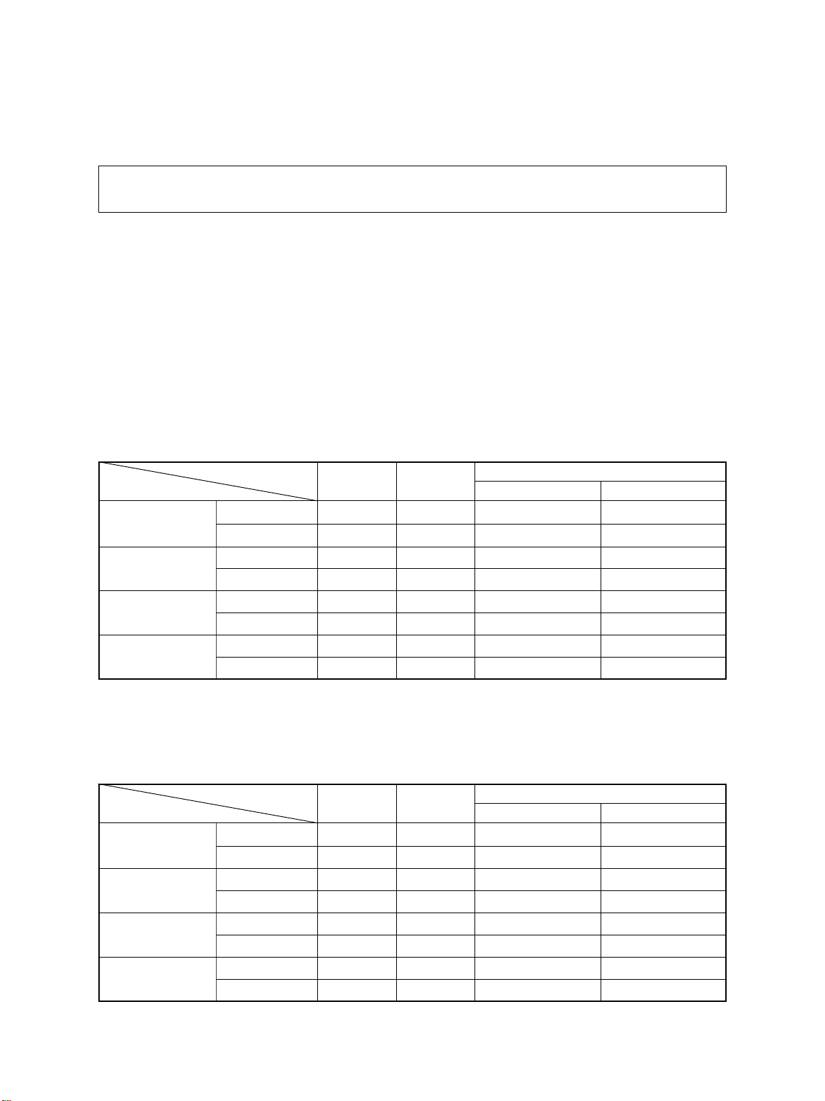
• Copy speed
e-STUDIO550 (Copies/min.)
Paper supply Tandem
Paper size Size specified Size not specified
A4, LT, B5
A4-R, B5-R,
A5-R, L T-R, ST-R
B4, LG
A3, LD
T op side discharging
Back side discharging
T op side discharging
Back side discharging
T op side discharging
Back side discharging
T op side discharging
Back side discharging
Cassette
55 55 48 33
55 55 48 30
44 — 42 33
42 — 42 30
39 — 37 33
35 — 35 30
34 — 33 33
30 — 30 30
LCF
Bypass feeding
e-STUDIO650
Paper supply Tandem
Paper size Size specified Size not specified
A4, LT, B5
A4-R, B5-R,
A5-R, L T-R, ST-R
B4, LG
A3, LD
JUNE 2002 © TOSHIBA TEC 1 - 1 e-STUDIO550/650/810 SPECIFICATIONS
T op side discharging
Back side discharging
T op side discharging
Back side discharging
T op side discharging
Back side discharging
T op side discharging
Back side discharging
Cassette
65 65 48 33
65 65 48 33
50 — 42 33
48 — 42 33
43 — 37 33
40 — 37 33
37 — 33 33
34 — 33 33
LCF
Bypass feeding
(Copies/min.)
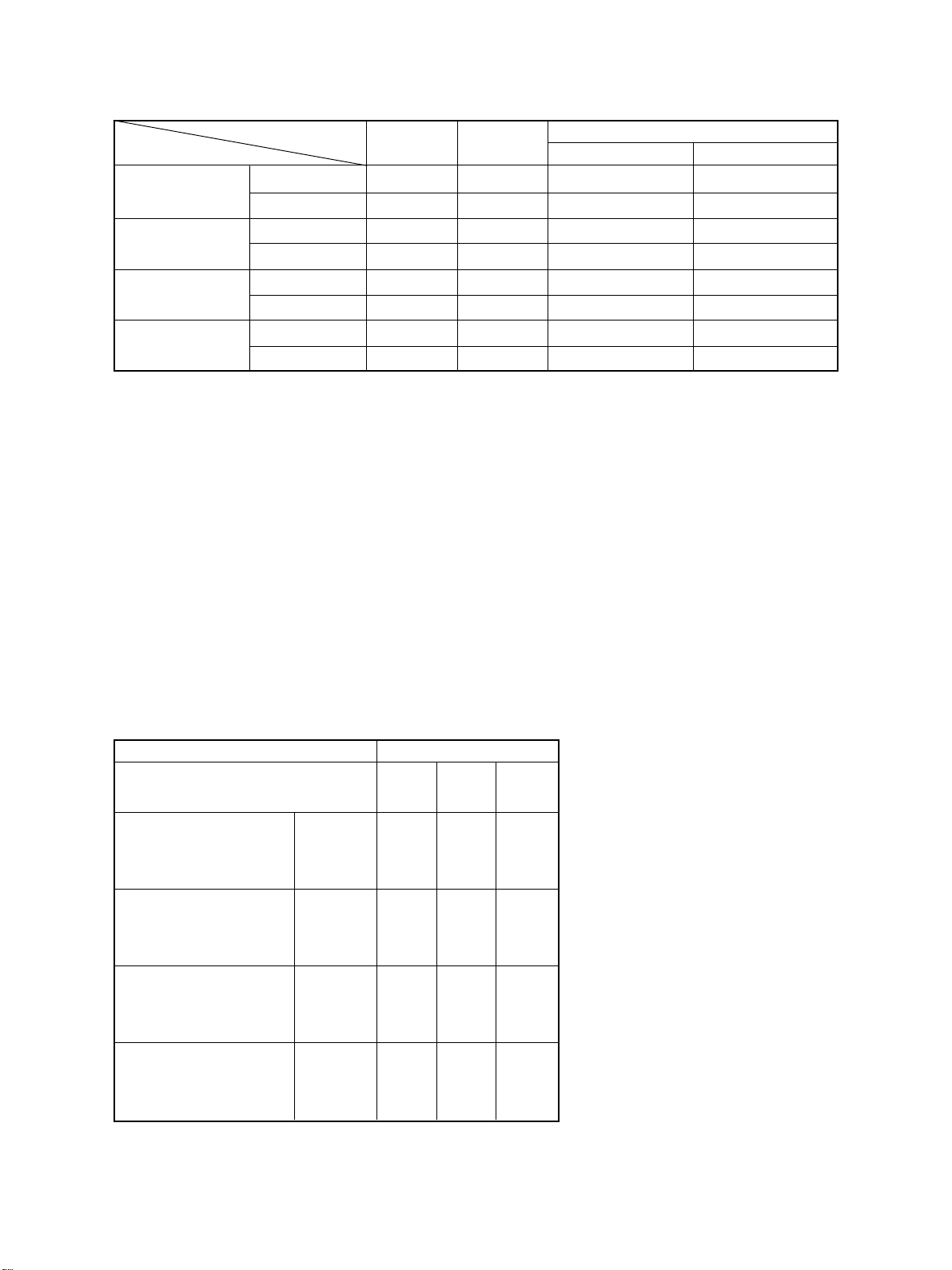
e-STUDIO810
(Copies/min.)
Paper supply
Paper size Size specified Size not specified
A4, LT, B5
A4-R, B5-R,
A5-R, L T-R, ST-R
B4, LG
A3, LD
“–” means “Not acceptable”.
*
Each copy speed described in the table of the previous page is available when doing a multiple copying
*
of the manually placed single-sided originals, and in this mode, only the top side discharging is carried
out.
When using the automatic document f eeder, each copy speed of 55 [65] {81} copies/min. is a vailable
*
only when the following conditions are met:
• Original/Mode : Single-sided original, A4/LT size, 1 sheet/APS and automatic
• Preset number of sheets: 55 [65] {81} or more.
• Reproduction ratio : 100%
T op side discharging
Back side discharging
T op side discharging
Back side discharging
T op side discharging
Back side discharging
T op side discharging
Back side discharging
Cassette
81 81 50 34
81 81 50 34
61 — 44 34
56 — 44 34
52 — 39 34
45 — 39 34
43 — 34 34
37 — 34 34
density are not selected.
Tandem
LCF
Bypass feeding
System copy speed
*
Copy mode
e-STUDIO e-STUDIO e-STUDIO
550 650 810
Single-sided originals 1 set 18"86 16"81 15"96
훹 3 sets 40"17 35"99 30"52
Single-sided copies 5 sets 61"92 53"56 45"19
Single-sided originals 1 set 21"28 20"70 20"46
훹 3 sets 42"91 39"47 36"37
Double-sided copies 5 sets 64"89 57"70 49"48
Double-sided originals 1 set 35"32 35"21 34"36
훹 3 sets 78"61 71"70 63"89
Double-sided copies 5 sets 121"96 108"01 95"06
Double-sided originals 1 set 31"77 31"49 30"88
훹 3 sets 74"75 67"97 60"58
Single-sided copies 5 sets 117"88 104"64 90"02
e-STUDIO550/650/810 SPECIFICATIONS 1 - 2 JUNE 2002 © TOSHIBA TEC
sec.
System copy speed, including
*
scanning time, is available when 10
sheets of A4-sized original are set
on RADF and one of the copy modes
in the left table is selected.
1st cassette is selected and copying
*
is at the sort mode.
Finisher, hole-punch unit and inserter
*
are installed.
Measurement deviation is included
*
since the system copy speed was
measured by actual measurement.

• Copy paper
Cassette Duplex copy LCF Bypass copy Remarks
Size A3~A5R, A4, LT A3~A5-R, LD~ST-R, No guarantee for 8K,
LD~ST-R, 13"LG, 8.5"x8.5", 8.5"x8.5", 8K, 16K, 16K-R 16K, 16K-R at duplex
8K, 16K, 16K-R
(Non-standard or user-
copy
specified sizes can be set.)
Weight 64~209g/m2, 17~110lb. -inde x 64~209g/m
2
17Ib~110Ib -index
Special Tab paper _
paper
(2nd casette only) OHP film (thickness: should be recommanded
T racing paper , labels, Special types of paper
80µm or thicker), tab paper by T oshiba.
• First copy time ..................3.3 seconds or less (A4/LT , LCF, 100%, original placed manually)
• Warming-up time ................Approx.160 seconds (e-STUDIO550/650/810, Temperature: 20°C)
Notes: 1. This is at the condition not entering the toner supply operation.
2. The auto job start is not operated.
• Multiple copying.................Up to 9999 copies; set number entered with digital keys
• Reproduction ratio..............Actual ratio: 100±0.5%
Zooming: 25~400% in increments of 1%
(25~200% when using the RADF)
• Resolution/Gradation ......... Read: 600 dpi
.........Write: Equivalent to 2400 dpi x 600 dpi
(primary scanning only : 4 division smoothing)
• Eliminated image width......Leading edge: 3.0±1.0 mm, Trailig edge: 2.0±1.0 mm, Side edges: 2.0±2.0 mm
• P aper f eeding.....................Automatic feeding: Copier cassettes–2 cassettes (Paper stac k height
55 mm, equivalent to 550 sheets; 64 to 80 g/m2 (17
to 22 lb.Bond))
LCF (Paper stac k height 137 mm: equiv alent to 2500
sheets; 64 to 80 g/m2, 17 to 22 lb.Bond)
Bypass feeding: (Paper stac k height 11 mm : equivalent to 100 sheets;
64 to 80 g/m2, 17 to 22 lb.Bond)
• Capacity of originals in the automatic document feeder
.................A3~A5-R, LD~ST-R
: 100 sheets
• Automatic duplexer............Stackless, Switchback type
• Toner supplying..................Automatic toner density detection/supply
T oner cartridge replacing method
(There is a recycle toner supplying system.)
JUNE 2002 © TOSHIBA TEC 1 - 3 e-STUDIO550/650/810 SPECIFICATIONS
• Density control ..................Automatic density mode and manual density mode selectable in 11 steps
• Weight ............................... Approx. 200kg, 441lb
• P ow er requirements ........... AC 115V/15A, AC 220 – 240V/10A
• Power consumption ...........2.0 kW or less (115V series, 200V series)
The electric power is supplied to the finisher and external LCF (optional) through the copier .
*
• T otal counter ......................Electronic counter
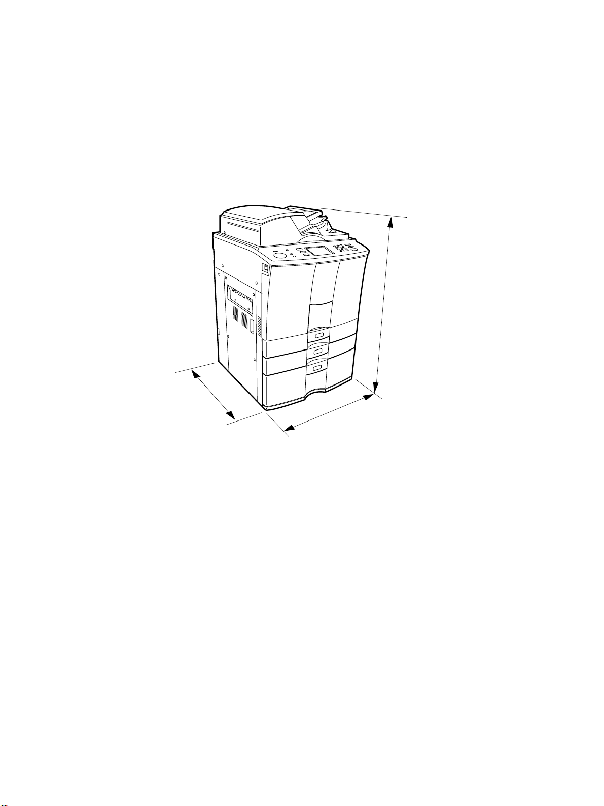
• Dimensions of the copier ... See the figure below . (W698x D778 x H1207 mm)
1207 mm
778 mm
698 mm
e-STUDIO550/650/810 SPECIFICATIONS 1 - 4 JUNE 2002 © TOSHIBA TEC

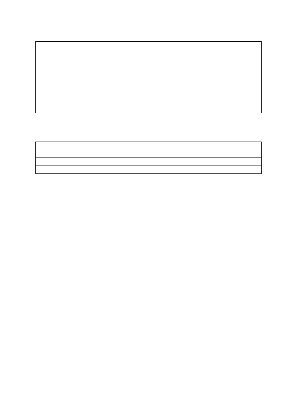
1. 2. Accessories
Unpacking/setup instruction 1 pc.
Operator’s Manu al 1 pc. (not available for MJD)
PM sticker 1 pc. (for MJD)
Setup report 1 set. (for NAD and MJD)
Customer satisfaction card 1 pc. (for MJD)
Operator’s Manual pocket 1 pc.
P ow er cable 1 pc. (for ASD, AUD and MJD)
Warr anty sheet 1 pc. (for NAD)
Drum 1 pc.
Drum cover 1 pc.
Original feeding tray 1 pc.
Tab paper end guide 1 pc.
* Machine version
NAD: North America
MJD: Europe
AUD: Australia
ASD: Asia
JUNE 2002 © TOSHIBA TEC 1 - 5 e-STUDIO550/650/810 SPECIFICATIONS
1. 3. Options
Finisher MJ-1017, MJ-1018
Hole punch unit MJ-6003N/E/F/S
Inserter MJ-7001
Staple cartridge STAPLE-600/STAPLE-700 (for saddle stitcher)
External large capacity feeder MP-4003A/L
Key copy counter/Key copy counter socket MU-8/MU-10
Damp heater kit MF-6510U/E
Printer controller GL-1020
Printer board GA-1140
1. 4. Supplies
Drum OD- 6510
Developer material D-6510
T oner PS-ZT6510/PS-ZT6510/PS-ZT -6510D
T oner bag PS-TB6510/PS-TB6510E
e-STUDIO550/650/810 SPECIFICATIONS 1 - 6 JUNE 2002 © TOSHIBA TEC
1. 5. System List
Ke y counter
Key counter socke t
MU-10
MU-8
LCF
MP-4003
Printer board
GA-1140
Finisher
MJ-1017
Staple cartridge
STAPLE-600
Inserter
MJ-7001
Hole punch unit
MJ-6003
Finisher
MJ-1018
Staple cartridge
STAPLE-700
Printer controller
GL-1020
JUNE 2002 © TOSHIBA TEC 1 - 7 e-STUDIO550/650/810 SPECIFICATIONS

2. OUTLINE OF THE MACHINE
2. 1. Sectional View
2. 2. Electric Parts Layout
2. 3. Symbols and Functions of Various Components
2. 4. Symbols and Functions of RADF Various Components
2. 5. System Block Layout
2. 6. Disassembly and Replacement of Covers and PC Boards
2. 6 . 1. Covers
2. 6. 2. PC boards

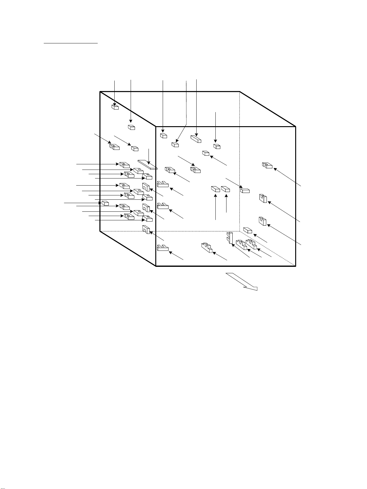
2. OUTLINE OF THE MACHINE
2. 1. Sectional View
[A] Front side vie w
32
33
34
35
36
43
44
37
38
39
45
46
5 6
4
21
3
47 48 49 50
40 41
42
19
17
18
16
30
31
1213
1415
7
10 11
89
20 21
26
272829
51
60
23
22
24
25
52
54
55
53
56
57
58
59
61
62
63
64
69
70
71
JUNE 2002 © TOSHIBA TEC 2 - 1 e-STUDIO550/650/810 OUTLINE OF THE MACHINE
68
65
66
67

1 Exposure lamp
41 Thermostat
2 Reflector
3 Mirror 1
4 Mirror 2
5 Mirror 3
6 Original glass
7 Lens
8 CCD driving PC board
9 Scanner control PC board
10 Drum
11 Drum thermistor
12 Charger wire cleaner
13 Main charger
14 Discharge LED
15 Drum cleaning b lade
16 Drum cleaning brush
17 Drum recov erly blade
18 Image quality sensor
19 Drum separation finger
42 Pressure roller thermistor
43 Exit roller
44 R e verse/e xit s witching gate
45 R e verse path roller 1
46 R e verse path roller 2
47 Transfer roller 1
48 Transfer roller 2
49 Transfer roller 3
50 Transfer roller 4
51 Registr ation roller
52 Bypass tr ansf er roller
53 Bypass separ ation roller
54 Bypass feed roller
55 Bypass pic kup roller
56 Intermiditate transf er roller
57 1st cassette tr ansf er roller
58 1st cassette feed roller
59 1st cassette separ ation roller
21 Upper de v eloper sleev e
22 L ower de v eloper sleev e
(Magnetic roller)
(Magnetic roller
23 Doctor b lade
24 Scattered toner reco v ery roller
25 A uto-toner sensor
26 Transfer belt driv en roller
27 Transfer belt po wer supply roller
28 Transfer belt
29 Transfer belt driv e roller
30 Transfer belt cleaning b lade
31 Transfer belt cleaning brush
32 Cleaning w eb
33 Cleaning w eb pushing roller
34 Fuser roller
35 Separ ation finger
36 Fuser exit roller
37 Pressure roller
38 Cleaning roller (metal)
60 1st cassette pic kup roller
)
61 2nd cassette transfer roller
62 2nd cassette feed roller
63 2nd cassette separ ation roller
64 2nd cassette pic kup roller
65 Tandem LCF transfer roller
66 Tandem LCF feed roller
67 Tandem LCF separation roller
68 Tandem LCF cassette pickup roller
69 1st cassette
70 2nd cassette
71 Tandem LCF tra y
39 Cleaning roller (f elt)
40 Fuser roller thermistor
e-STUDIO550/650/810 OUTLINE OF THE MACHINE 2 - 2 JUNE 2002 © TOSHIBA TEC
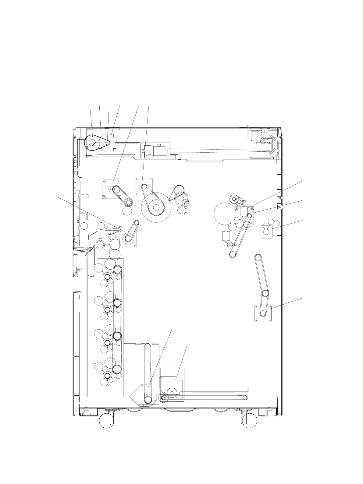
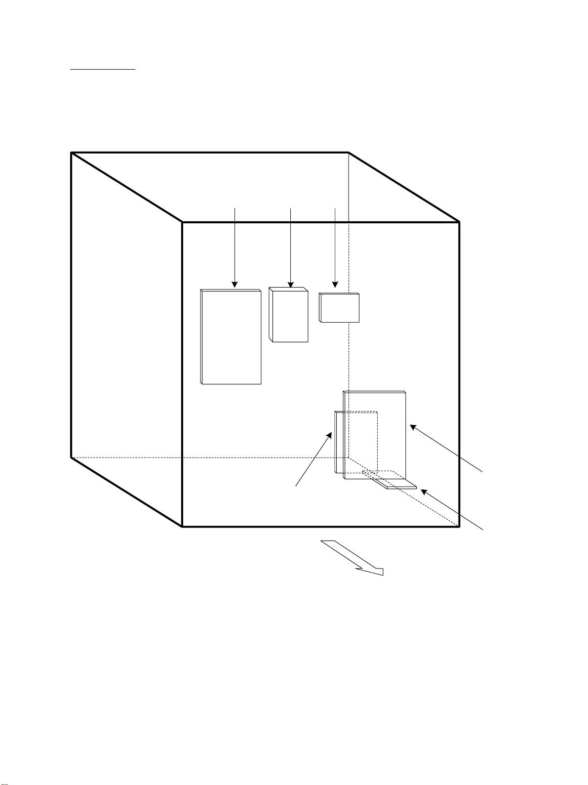
[B] Rear side view (Drive system)
1234
7
65
9
8
10
11
12
13
JUNE 2002 © TOSHIBA TEC 2 - 3 e-STUDIO550/650/810 OUTLINE OF THE MACHINE

1 Scanner motor
2 Drive pulley
3 Drive belt
4 Driven pulley
5 Drum motor
6 Dev eloper unit motor
7 Registration motor
8 Fuser motor
9 Web motor
10 Exit motor
11 R e v erse motor
12 LCF tr ay-up motor
13 LCF end fence motor
e-STUDIO550/650/810 OUTLINE OF THE MACHINE 2 - 4 JUNE 2002 © TOSHIBA TEC
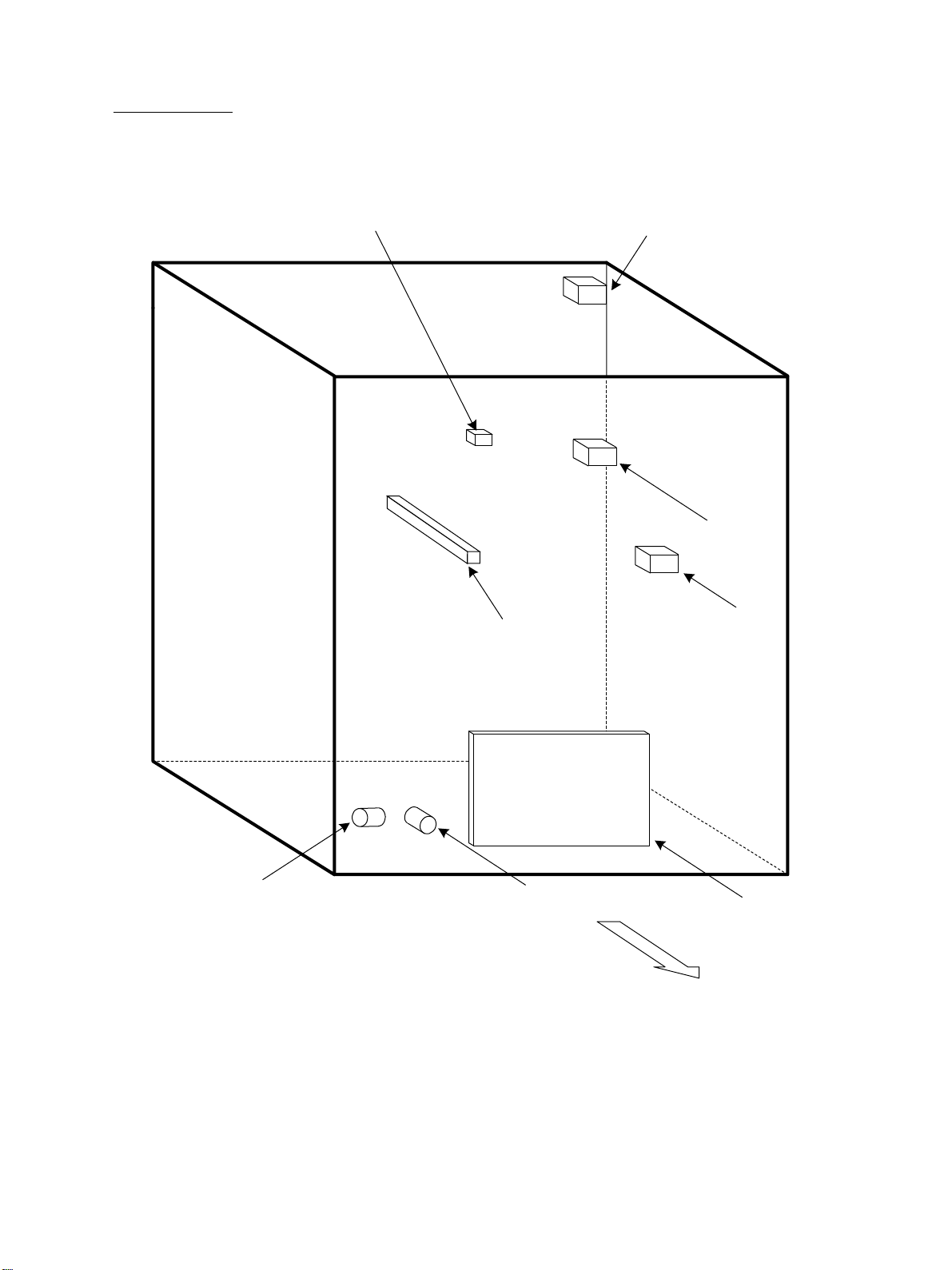
2. 2. Electric Parts Layout
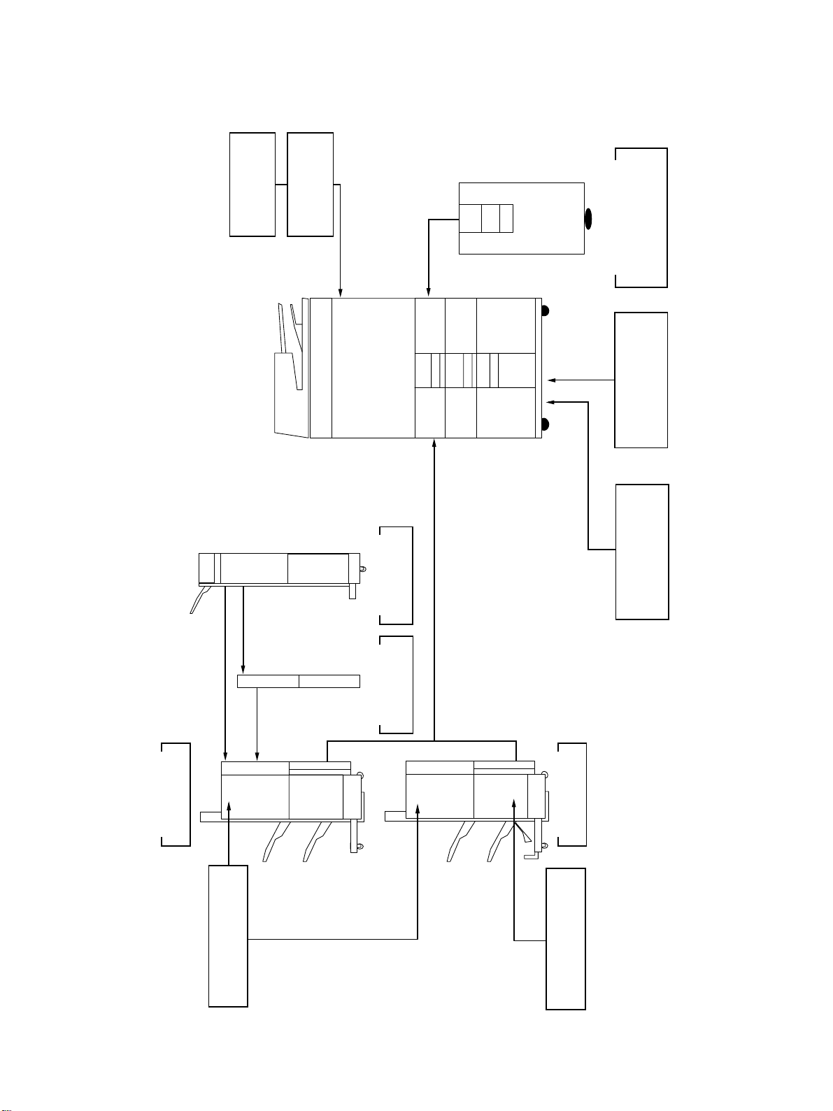
[A] Unit construction
Reversing automatic document f eeder unit
Scanner unit
Laser unit
T r ansfer/Transport unit
Copier unit
Fuser unit
Rear side
JUNE 2002 © TOSHIBA TEC 2 - 5 e-STUDIO550/650/810 OUTLINE OF THE MACHINE
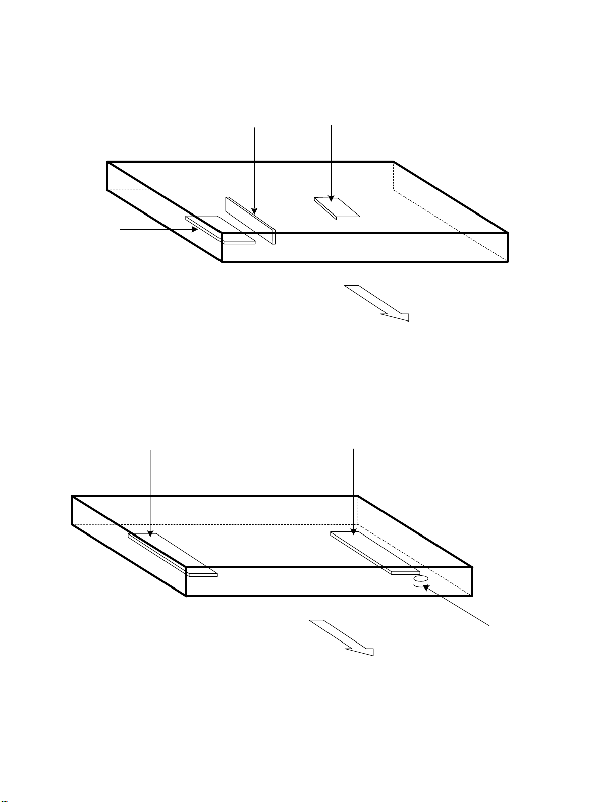
[B] Scanner unit
(B-1) Motor/Exposure lamp
(B-2) Sensor/Switch
A4 series
M31
M1
S1-5
EXP
Rear side
S1-5
S1-5
S1-5
S1-5
S2
Rear side
S1-4
S1-4
LT series
S1-4
S1-4
S2
Rear side
e-STUDIO550/650/810 OUTLINE OF THE MACHINE 2 - 6 JUNE 2002 © TOSHIBA TEC
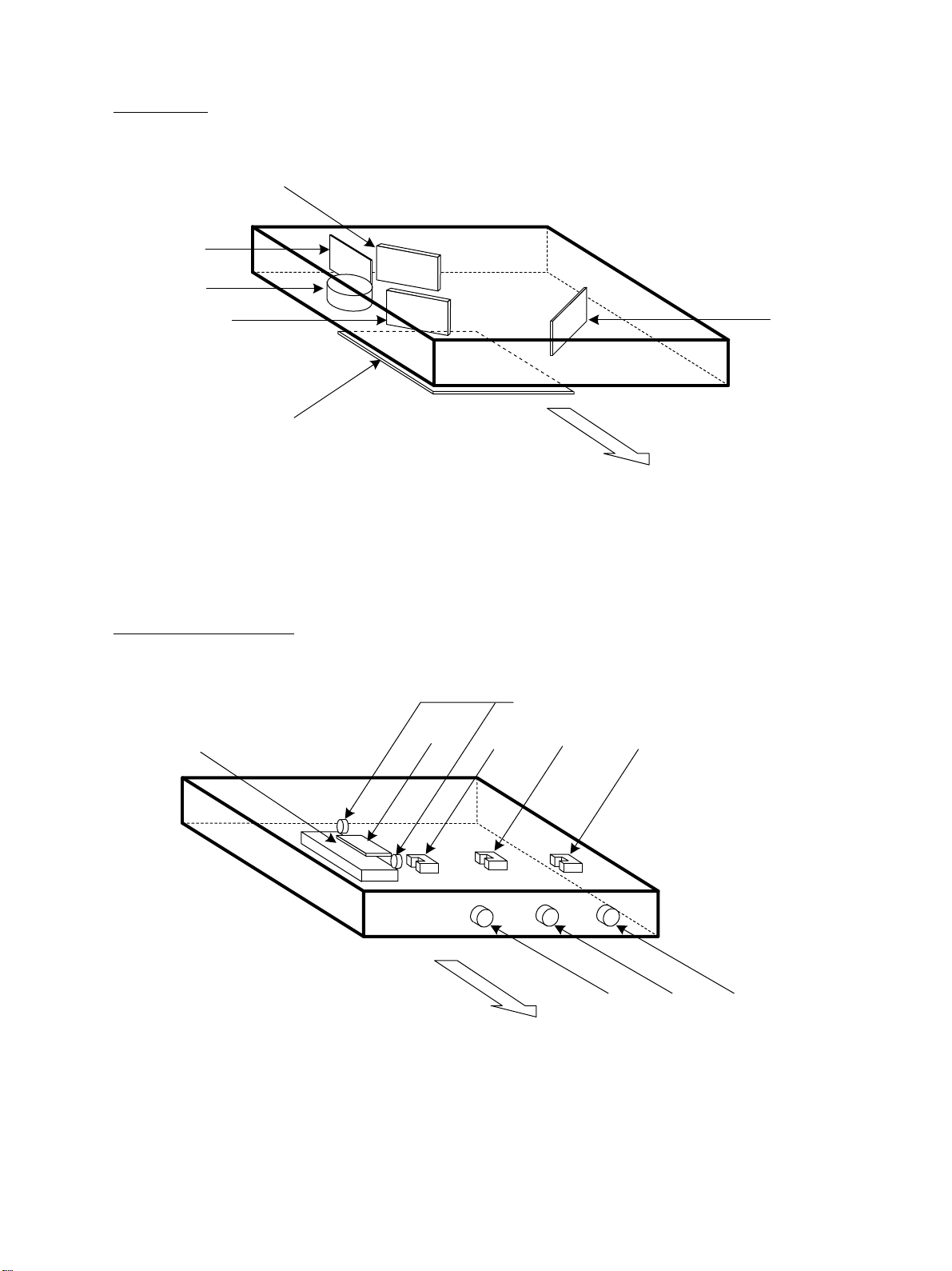
(B-3) PC board
SLG
(B-4) Other parts
CCD
INV
Rear side
DHR
DHL
THMO4
Rear side
JUNE 2002 © TOSHIBA TEC 2 - 7 e-STUDIO550/650/810 OUTLINE OF THE MACHINE
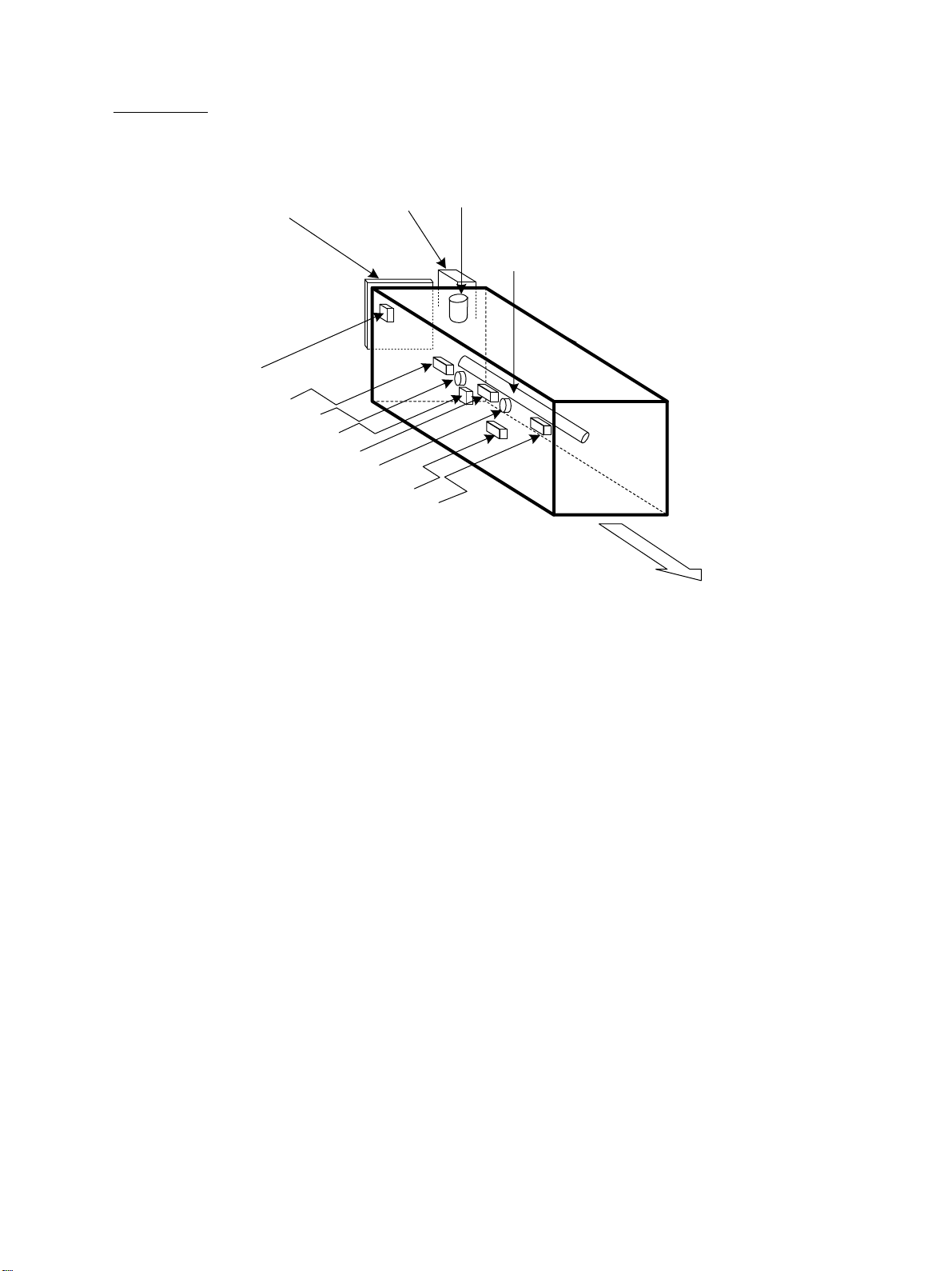
[C] Laser unit
LDR1
M2
GLV
LDR2
PLG
[D] T ransfer/Transport unit
DHT
FUSE
S5
THMO3
S4
SNS
Rear side
S3
CLT3
CLT1CLT2
Rear side
e-STUDIO550/650/810 OUTLINE OF THE MACHINE 2 - 8 JUNE 2002 © TOSHIBA TEC
[E] Fuser unit
S6
THM1
THMO2
IH
S7
THM2
THMO1
M30
THM5
THM3
M3
IHCOIL
Rear side
JUNE 2002 © TOSHIBA TEC 2 - 9 e-STUDIO550/650/810 OUTLINE OF THE MACHINE

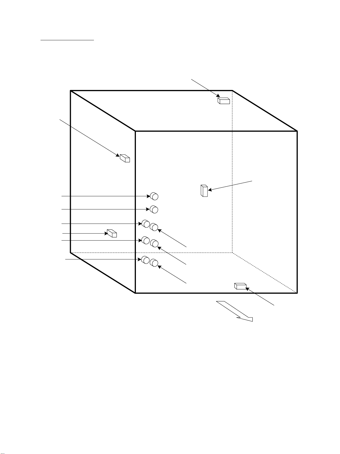
[F] Copier unit
(F-1) Motor/Fa n
M19
M20
M26
M27
M28
M29
M18
M17
M25
M24
M16
M15
M21
M22
M14
M13
M23
M12
M11
M10
M9
M8
M7
M6
M4
M5
M32
Rear side
e-STUDIO550/650/810 OUTLINE OF THE MACHINE 2 - 10 JUNE 2002 © TOSHIBA TEC
(F-2) Clutch/Solenoid
SOL1
CLT4
SOL2
SOL3
CLT5
CLT6
SOL5
CLT8
CLT10
CLT7
CLT9
CLT11
SOL4
Rear side
JUNE 2002 © TOSHIBA TEC 2 - 11 e-STUDIO550/650/810 OUTLINE OF THE MACHINE
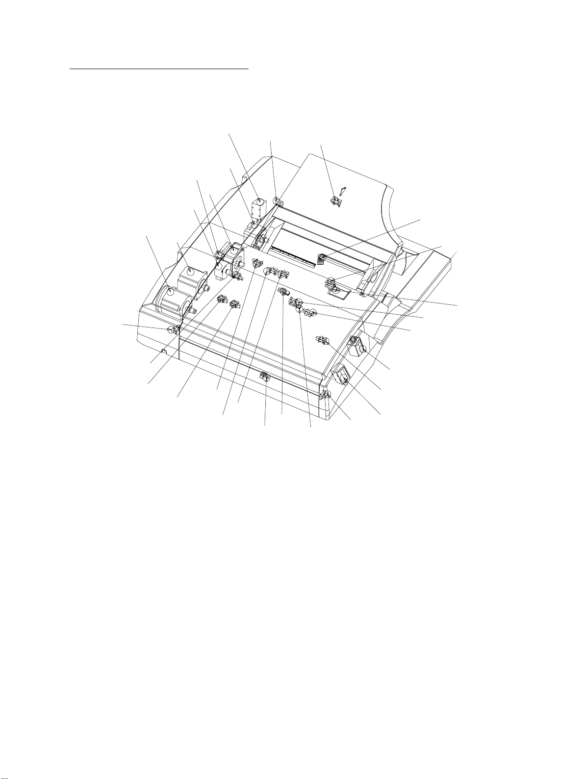
(F-3) Sensor/Switch
S25
S26
S32
S38
S27
S33
S39
S28
S34
S40
S49
S29
S35
S41
S52
S50
S14
S51
S15
S31
S37
S42
S21
S30
S36
S16S17
S20
S19
S22
S24
S23
S18
S13
S10
S11
S12
S43
S44
S47
Rear side
S46S45
e-STUDIO550/650/810 OUTLINE OF THE MACHINE 2 - 12 JUNE 2002 © TOSHIBA TEC
(F-4) PC board
SYS
HDD
MOT
LGC
HVT
MOT2
Rear side
JUNE 2002 © TOSHIBA TEC 2 - 13 e-STUDIO550/650/810 OUTLINE OF THE MACHINE
(F-5) Other parts
THM4
S8
S9
S48
ERS
NF1
BRK1
PS
Rear side
e-STUDIO550/650/810 OUTLINE OF THE MACHINE 2 - 14 JUNE 2002 © TOSHIBA TEC
[G] Reversing automatic document f eeder
APS
RMOT
DLMTS
SIZE2
TLMOT
FMOT
SIZE1
COPSW
LMOT
SSOL
SMOT
COPS
EMPS
a
b
LLMTS
DFOPSW
READS
LNGS
TRYS
LOES
c
DFOPEN
TRVR
SOES
SSBS
REGS
ITFS
RSOL
SIZE3
LSOL
JUNE 2002 © TOSHIBA TEC 2 - 15 e-STUDIO550/650/810 OUTLINE OF THE MACHINE

2. 3. Symbols and Functions of Various Components
The column <P-I> shows the page and item number in the parts list.
(1) Motors
Symbol Name Function P-I Remarks
M1 SCAN-MOT Driving of the carriages 33-6 (B-1)
Scanner motor
M2 M/DC-POL Driving of the polygonal mirror 31-10 [C]
Polygonal motor
M3 WEB-MOT Cleaning web take-up 25-29 [E]
Web motor
M4 FEED-MOT Driving of the feeding section 6-2 (F-1)
Feed motor
M5 CST-TRY-MOT1 Driving ups of the 1st and 6-20 (F-1)
Cassette tray-up motor 2nd cassettes
M6 CST -TRY-MOT2 Driving ups of the tandem LCF tray 6-20 (F-1)
Casette tray-up motor 2
M7 RGST-MOT Driving of the registration roller 6-26 (F-1)
Registration motor
M8 DEV-MOT Driving of the developer unit 40-22 (F-1)
Developer unit motor
M9 DRUM-MOT Driving of the drum 39-18 (F-1)
Drum motor
M10 TRB-CAM-MOT Contact/Release of the transfer belt 18-7 (F-1)
Transfer belt cam motor
M11 REV-MOT Dr iving of the reverse section 13-5 (F-1)
Reverse motor
M12 USTNR-AUG-MOT Recovery of the toner scraped with 45-2 (F-1)
Used toner transport motor the transfer belt cleaning blade
M13 EXIT-MOT Driving of the exit roller 13-25 (F-1)
Exit motor
M14 FUSER-MOT Driving of the fuser unit 24-5 (F-1)
Fuser motor
M15 TRB-MOT Driving of the transfer belt 18-26 (F-1)
Transfer belt motor
M16 FUR-MOT Dr iving of the transfer belt cleaning 30-12 (F-1)
Cleaning brush drive motor brush
M17 CH-CLN-MOT Driving of the charger wire cleaner 37-8 (F-1)
Charger wire cleaner drive motor
M18 TNR-MOT Toner supply 44-27 (F-1)
New toner supply motor
M19 TNR-RCY-HOP-MOT Driving of the recycle toner hopper 46-15 (F-1)
Toner recycle hopper motor
M20 RCY-TNR-MOT Transpor ting of the recycle toner 46-19 (F-1)
Recycle toner transport motor
M21 HTR-FAN-MOT Cooling down of the copier inside 31-7 (F-1)
Heater fan motor
e-STUDIO550/650/810 OUTLINE OF THE MACHINE 2 - 16 JUNE 2002 © TOSHIBA TEC

Symbol Name Function P-I Remarks
M22 ADU-FAN-MOT1 Cooling down the reverse section 15-12 (F-1)
Reverse section fan motor 1
M23 ADU-FAN-MOT2 Cooling down the reverse section 15-12 (F-1)
Reverse section fan motor 2
M24 EXIT-FAN-MOT Cooling down of the exit section 31-7 (F-1)
Exit fan motor
M25 DUCT-OUT-FAN-MOT Sucking of ozone 31-7 (F-1)
Duct out fan motor
M26 LSU-FAN-MOT Cooling down of the laser unit 31-7 (F-1)
Laser unit fan motor
M27 DUCT-IN-FAN-MOT Cooling down of the copier inside 40-25 (F-1)
Duct in fan motor
M28 SYS-FAN-MOT Cooling down of the copier inside 52-24 (F-1)
System fan motor
M29 DEV-FAN-MOT Sucking of the toner in the developer 40-13 (F-1)
Developer unit fan motor unit
M30 IH-FAN-MOT Cooling down of the IH board 24-17 [E]
IH fan motor
M31 SLG-FAN-MOT Cooling down of the SLG board 32-10 (B-1)
SLG fan motor
M32 END-F-MOT Moving of the end fence 9-22 (F-1)
End fence motor
JUNE 2002 © TOSHIBA TEC 2 - 17 e-STUDIO550/650/810 OUTLINE OF THE MACHINE

(2) Sensos and switches
Symbol Name Function P-I Remarks
S1-5 APS 1-5 Original size detection 36-6 (B-2)
Automatic original detection sensor
S2 HOME-SNR Carriage home position detection 36-12 (B-2)
Carriage home position sensor
S3 TR-SNR 1 Paper detection at the reversed 20-23 [D]
Transpor t sensor 1 paper transport path
S4 TR-SNR 2 Paper detection at the reversed 20-23 [D]
Transpor t sensor 2 paper transport path
S5 TR-SNR 3 Paper detection at the reversed 20-23 [D]
Transpor t sensor 3 paper transport path
S6 WEB-SNR Cleaning web take-up amount 25-8 [E]
Web detection sensor detection
S7 FUS-EXIT-SNR Paper detection at the fuser unit 25-8 [E]
Fuser unit exit sensor
S8 MAIN-SW ON/OFF of the copier AC power 28-11 (F-5)
Main switch supply
S9 DOOR-SW Turning OFF of the AC power supply 28-24 (F-5)
Front door switch when opening the front cover
Interlock switch
S10 EXIT-SNR Paper detection at the exit section 15-25 (F-3)
Exit sensor
S11 RVS-SNR Paper detection at the reverse section 15-14 (F-3)
Reverse sensor 1
S12 RVS-SNR Paper detection at the reverse section 15-14 (F-3)
Reverse sensor 2
S13 EXIT-COV-SW Cover open/close detection at the 15-11 (F-3)
Exit cover switch exit cover
S14 DEV-SW Detection of the developer unit 5-16 (F-3)
Developer unit switch presence or absence
S15 TNR-SW Toner car tridge detection 44-18 (F-3)
Toner cartridge switch
S16 DRUM-SUF-SNR Detection of the drum surface 5-13 (F-3)
Drum surface potential sensor potential
S17 ATTNR-SNR Toner density detection 42-26 (F-3)
Auto-toner sensor
S18 TNLVL-SNR Toner adhesion amount detection 49-16 (F-3)
Image quality sensor
S19 CH-HOME-SW Detection of the wire cleaner home 37-13 (F-3)
Wire cleaner home position switch position
S20 MID-TR-SNR Paper detection at the feeding section 17-6 (F-3)
Intermediate transport sensor
S21 RGST-SNR Paper detection at the registration 16-6 (F-3)
Registration sensor section
S22 TR-BELT-SW 1 Transfer belt release position 18-3 (F-3)
Transfer belt release switch detection
e-STUDIO550/650/810 OUTLINE OF THE MACHINE 2 - 18 JUNE 2002 © TOSHIBA TEC

Symbol Name Function P-I Remarks
S23 TR-BELT-SW 2 Transfer belt contact position 18-2 (F-3)
Transfer belt contact switch detection
S24 TNR-FULL-SNR Used toner full detection 45-17 (F-3)
Toner bag full detection sensor
S25 COV-R-SNR Feed cover open/close detection 28-7 (F-3)
Feed cover sensor
S26 CST1-TR-SNR 1st cassette paper detection 7-18 (F-3)
1st cassette transport sensor
S27 CST1-TRY-SNR 1st cassette tray position detection 7-18 (F-3)
1st cassette tray-up sensor
S28 CST1-FED-SNR 1st cassette paper detection 7-18 (F-3)
1st cassette feed sensor
S29 CST1-EMP-SNR Detection of 1st cassette paper 7-18 (F-3)
1st cassette empty sensor presence or absence
S30 CST1-BTM-SNR 1st cassette position lower limit 7-18 (F-3)
1st cassette bottom sensor detection
S31 CST1-SNR Detection of 1st cassette presence or 7-18 (F-3)
1st cassette detection sensor absence
S32 CST2-TR-SNR 2nd cassette paper detection 7-18 (F-3)
2nd cassette transport sensor
S33 CST2-TRY-SNR 2nd cassette tray position detection 7-18 (F-3)
2nd cassette tray-up sensor
S34 CST2-FED-SNR 2nd cassette paper detection 7-18 (F-3)
2nd cassette feed sensor
S35 CST2-EMP-SNR Detection of 2nd cassette paper 7-18 (F-3)
2nd cassette empty sensor presence or absence
S36 CST2-BTM-SNR 2nd cassette position lower limit 7-18 (F-3)
2nd cassette bottom sensor detection
S37 CST2-SNR Detection of 2nd cassette presence 7-18 (F-3)
2nd cassette detection sensor or absence
S38 LCF-TR-SNR Paper detection at the tandem LCF 7-18 (F-3)
Tandem LCF transpor t sensor feeder section
S39 LCF-TRY-SNR Tandem LCF tray position detection 7-18 (F-3)
Tandem LCF tray-up sensor
S40 LCF-FED-SNR Paper detection at the tandem LCF 7-18 (F-3)
Tandem LCF feed sensor feeder section
S41 LCF-EMP-SNR Detection of paper presence or 7-18 (F-3)
Tandem LCF empty sensor absence at tandem LCF
S42 LCF-SNR Detection of the tandem LCF tray 7-18 (F-3)
Tandem LCF detection sensor presence or absence
S43 LCF-BTM-SNR Tray home position detection 8-14 (F-3)
Tandem LCF bottom sensor
S44 END-F-STP-SNR End fence stop position detection 8-14 (F-3)
End fence stop position sensor
JUNE 2002 © TOSHIBA TEC 2 - 19 e-STUDIO550/650/810 OUTLINE OF THE MACHINE

Symbol Name Function P-I Remarks
S45 EMP-SNR-SS Paper position detection at the 18-14 (F-3)
Standby side empty sensor standby side
S46 END-F-HP-SNR End fence home position detection 18-14 (F-3)
End fence home position sensor
S47 PR-MST-SS Detection of the paper mis-stacking 18-16 (F-3)
Standby side paper mis-stacking sensor at the standby side
S48 HTR-SW Detection of the fuser unit presence 24-7 (F-5)
Fuser unit switch or absence
S49 SFB-COV-SNR Open/close detection of the bypass 28-7 (F-3)
Bypass feed unit cover sensor feed unit cover
S50 SFB-FED-SNR Paper detection at the bypass feeding 10-23 (F-3)
Bypass sensor
S51 SFB-SIZE-SNR Paper size detection at the bypass 12-9 (F-3)
Bypass paper size detection sensor feed width detection
S52 TEMP/HUMI-SNR Detection of the temperature and 3-103 (F-3)
Temperature/humidity sensor humidity of the copier inside
e-STUDIO550/650/810 OUTLINE OF THE MACHINE 2 - 20 JUNE 2002 © TOSHIBA TEC

(3) Electromagnetic spring clutches
Symbol Name Function P-I Remarks
CLT1 TR-DRV-CLT Dr iving of the reversed paper 19-21 [D]
Reversed paper transport driving clutch transpor t section
CLT2 REV-TR1-CLT Reversed paper transporting 20-21 [D]
Reversed paper transport clutch 1
CLT3 REV-TR2-CLT Reversed paper transporting 20-21 [D]
Reversed paper transport clutch 2
CLT4 MDL-TR-CLT Paper transporting 17-23 (F-2)
Intermediate transport clutch
CLT5 SFB-FEED-CLT Driving of the bypass pickup roller 11-13 (F-2)
Bypass feed clutch
CLT6 CST1-TR-CLT 1st cassette paper transporting 7-26 (F-2)
1st cassette transport clutch
CLT7 CST1-FED-CLT Driving of 1st cassette pickup roller 7-26 (F-2)
1st cassette feed clutch
CLT8 CST2-TR-CLT 2nd cassette paper transporting 7-26 (F-2)
2nd cassette transport clutch
CLT9 CST2-FED-CLT Driving of 2nd cassette pickup roller 7-26 (F-2)
2nd cassette feed clutch
CLT10 LCF-TR-CLT Tandem LCF paper transpor ting 7-26 (F-2)
Tandem LCF transpor t clutch
CLT11 LCF-FED-CLT Driving of the tandem LCF pickup 7-26 (F-2)
Tandem LCF feed clutch roller
(4) PC boards
Symbol Name Function P-I Remarks
SLG PWA-F-SLG Control of the scanning section and 36-1 (B-3)
Scanning section control PC board (SLG board) image processing
CCD PWA-F-CCD Preprocessing control of the CCD 32-17 (B-3)
CCD driving PC board (CCD board) image data
SYS PWA-F-SYS Control of the whole copier 52-10 (F-4)
System PC board (SYS board) Data processing
LGC PWA-F-LGC Control of the whole copier 52-14 (F-4)
Logic PC board (LGC board)
LDR1 PWA-F-LDR1 Driving of the laser diode 31-10 [C]
Laser driving PC board 1 (LDR board 1)
LDR2 PWA-F-LDR2 Driving of the laser diode 31-10 [C]
Laser driving PC board 2 (LDR board 2)
SNS PWA-F-SNS Detection of the laser beam position 31-10 [C]
H-Sync detection PC board
IH PS-IH Control of the fuser unit IH coil 24-16 [E]
IH control board
FUSE PWA-F-FUS Cutting of the electric current to the 21-30 [D]
Fuse PC board damp heater
JUNE 2002 © TOSHIBA TEC 2 - 21 e-STUDIO550/650/810 OUTLINE OF THE MACHINE

Symbol Name Function P-I Remarks
MOT PWA-F-MOT Driving of the drum motor and 24-21 (F-4)
Motor driving PC board transfer belt motor
MOT2 PWA-F-MOT2 Driving of the reverse motor 13-19 (F-4)
Motor driving PC board 2
PLG PWA-F-PLG Control of the printing section and 31-16 [C]
Laser control PC board (PLG board) image processing
(5) Heaters and lamps
Symbol Name Function P-I Remarks
EXP LP-EXPO Exposing of original to the light 34-3 (B-1)
Exposure lamp
DHR DNP- HTR-R Preventing of the condensation in the 36-11 (B-4)
Scanner damp heater (R) scanning section (for mirrors)
DHL DNP-HTR-L Preventing of the condensation in the 36-9 (B-4)
Scanner damp heater (L) scanning section (for lens)
DHD D-HTR Keeping of the drum warm 21-28 [D]
Drum damp heater
IHCOIL IH-COIL Heating up of the fuser roller 25-36 [E]
IH coil
(6) Solenoid
Symbol Name Function P-I Remarks
SOL1 SFB-SOL Driving of the bypass pickup roller 10-8 (F-2)
Bypass pickup solenoid
SOL2 GATE-SOL Switching of the gate at the reverse 15-2 (F-2)
Gate solenoid section
SOL3 SEP-FING-SOL Driving of the dr um separation finger 30-17 (F-2)
Drum separation finger solenoid
SOL4 END-F-SOL Moving of the lever to detect the 8-9 (F-2)
End fence solenoid paper mis-stacking at the standby
side tray
SOL5 LCF-PICK-SOL Driving of the Tandem LCF pickup 7-36 (F-2)
Tandem LCF pickup solenoid roller
(7) Transformer
Symbol Name Function P-I Remarks
HVT PS-HVT Generating of the voltages for the 51-19 (F-4)
High-voltage transformer followings:
• main charger wire
• main charger grid
• developer bias
• drum cleaning brush
e-STUDIO550/650/810 OUTLINE OF THE MACHINE 2 - 22 JUNE 2002 © TOSHIBA TEC

(8) Others
Symbol Name Function P-I Remarks
INV INV-EXP Control of the exposure lamp 34-4 (B-3)
Lamp inverter
HDD HDD Storing of the image data 52-16 (F-4)
Hard disk
GLV MIR-GLV Control of the laser 31-10 [C]
Galvanometer mirror
PS PS-ACC Power supplying 51-18 (F-5)
Switching power supply
THMO1 THERMO-HTR Preventing of the fuser unit 26-4 [E]
Center thermostat over-heating
THMO2 THERMO-S-HTR Preventing of the fuser unit 26-4 [E]
Side thermostat over-heating
THMO3 DAMP-HTR Preventing of the dump heater 21-31 [D]
Dump heater thermostat over-heating
THMO4 THERMO-EXP Preventing of the dump heater 36-9 (B-4)
Expousre lamp thermostat over-heating in scanner section
THM1 THMS-S-HTR Detection of the surface temperature 26-6 [E]
Fuser roller side thermistor (front) at the drum edges/Abnormal detection
THM2 THMS-HTR Detection of the surface temperature 26-6 [E]
Fuser roller center thermistor at the drum center
THM3 THMS-S-HTR Detection of the surface temperature 26-6 [E]
Fuser roller side thermistor (rear) at the drum edges
THM4 THMS-DRM Detection of the drum surface 49-12 (F-5)
Drum thermistor
THM5 THMS-L-HTR Detection of the surface temperature 26-28 [E]
Pressure roller thermistor of the pressure roller
NF1 NOIZ-FILTER1 Noize cut 51-7 (F-5)
Noize filter 1
BRK1 BREAKER1 Safety switch 51-6 (F-5)
Breaker 1
BRK2 BREAKER2 Safety switch 51-6 (F-5)
Breaker 2
ERS CD-ERS Removing of the residual charge from 37-11 (F-5)
Discharge lamp the drum surface
JUNE 2002 © TOSHIBA TEC 2 - 23 e-STUDIO550/650/810 OUTLINE OF THE MACHINE

2. 4. Symbols and Functions of RADF Various Components
(1) Motors
Symbol Name Function Remarks
RMOT RMOT ·Driving of the transport roller Stepping motor
Read motor (P83-I27)
SMOT SMOT ·Driving of the small original exit roller Stepping motor
Small original exit motor and small original reverse roller (P87-I14)
TLMOT UDMOT ·Driving of the tray lift motor Stepping motor
Tray lift motor (P86-I20)
FMOT FMOT ·Driving of the f eed roller , pic kup roller Stepping motor
Feed motor and registration roller (P86-I19)
LMOT LMOT ·Driving of the large original e xit roller Stepping motor
Large original exit motor and large original reverse roller (P87-I13)
(2) Solenoids
Symbol Name Function Remarks
ESSOL ESSOL ·Disengagement of the large original DC solenoid
Disengagement solenoid exit roller (P89-I4)
LSOL LSOL ·Switching of the large original exit DC solenoid
Large original exit solenoid
SSOL SSOL ·Switching of the small original exit DC solenoid
Small original exit solenoid
flapper (P89-I3)
flapper and reverse flapper (P87-I1)
(3) PC boards
Symbol Name Function Remarks
DFLG PW A-F-ADF ·Control of the ADF (P88-I13)
ADF PC control board
(ADF board)
e-STUDIO550/650/810 OUTLINE OF THE MACHINE 2 - 24 JUNE 2002 © TOSHIBA TEC

(4) Switches and sensors
Symbol Name Function Remarks
COPSW COV-OPN-SW Detecting if the jam access cover is Mi cro switch
Cover open/close s witch opened/closed (Interlock switch) (P86-I13)
DFOPSW DF-OPN-SW Detecting if RADF is opened/closed Micro switch
RADF open/close switch (Interlock switch) (P88-I101)
DFOPNS DF-OPN-SNS Detecting if RADF is opened/closed Semiconductive
RADF open/close sensor photosensor (P89-101)
APS AUTO-PS-SNS Detecting the angle opened and Semiconductive
APS operation sensor switching ON/OFF of the APS sensor photosensor (P86-I105)
COPS COV-OPN-SNS Detecting if the jam access cover is Semiconductiv e
Cover open/close sensor opened/closed photosensor (P81-I29)
EMPS EMP-SNS Detecting the presence or absence of Semiconductive
Empty sensor original during feeding photosensor (P81-I29)
ULMTS UP-LMT-SNS Detecting the upper limit of the lifting tra y Semiconductive
Upper limit sensor photosensor (P81-I29)
SIZES1 SIZE-SNS1 Detecting the original width Semiconductiv e
Original width sensor 1 photosensor (P91-I103)
SIZES2 SIZE-SNS2 Detecting the original width Semiconductiv e
Original width sensor 2 photosensor (P91-I103)
SIZES3 SIZE-SNS3 Detecting the original width Semiconductiv e
Original width sensor 3 photosensor (P91-I103)
REGS REG-SNS Detecting original at the registering Semiconductive
Registration sensor section photosensor (P91-I103)
TRYS TRY-SNS Detecting the original length on the tray Semiconductive
Tray sensor photosensor (P93-I102)
LLMTS LO-LMT-SNS Detecting the lower limit of the lifting tray Semiconductive
Lower limit sensor photosensor (P82-I36)
ITFS INT-F-SNS Detecting original on the small original Semiconductive
Intermediate transpor t sensor
transport path photosensor (P90-I103)
SOES SO-EX-SNS Detecting original at the small original Semiconductiv e
Small original exit sensor e xit photosensor (P84-I105)
READS READ-SNS Detecting original at the scanning Semiconductive
Read sensor section photosensor (P83_I36)
LNGS LENG-SNS Detecting the original length Semiconductive
Original length sensor photosensor (P82-I31)
SSBS SO-SB-SNS Detecting original at the small original Semiconductive
Small original reverse sensor
reverse section photosensor (P84-I31)
TRV R TRY-VR Detecting the original width on the trayRotary volume
Tray width sensor (P93-I6)
LOES LO-EX-SNS Detecting original at the large original Semiconductive
Large original exit sensor exit photosensor (P85-I15)
JUNE 2002 © TOSHIBA TEC 2 - 25 e-STUDIO550/650/810 OUTLINE OF THE MACHINE

2. 5. System Block Layout
ADF
CCD
Serial-I/F
PWA-F-SLG-340
Flash
ROM
AmpAmp
CPU
32
or
ASIC
S-CPU
SRAM
Serial-I/F
32
Controller
Printer
A/DA/D
32
SDRAM
Image Data
ASIC
ADR/DAT-Bus
Image Data
32
16
SRAM
PCI-Bus
32
ASIC
16
IDE-I/F
Laser Unit
PWA-F-CCD2-340
PWA-F-PLG-340
JIG
Download
16
32
ROM
Flash
32
Local-
Bus
4
RTC
D/A
ROM
Flash
NVRAM
32
32
ASIC
8
LD
PWA-F-LDR-340
ASIC
Image Data
ASIC
32
SDRAM
PWA-F-LDR-340
32
LD
ASIC
PWA-F-SCN-340
8
8 8
PWA-F-SYS-340
SRAM
8
Laser
ROM
Flash
Image Data
Image Data
Beam
ASIC
D/A
ADR/DAT-Bus
Serial-I/F
Sensor
PWA-F-SNS-340
PWA-F-LGC-340
L-CPU
SRAM
SRAM
Gate
Mirror
Galvanic
DRV
Galvano
D/A
ROM
Flash
NVRAM
Serial-I/F
ADR/DAT-Bus
Array
ROM
Flash
M-CPU
Serial-I/F
ADR/DAT-Bus
PFC
IPC
LCF
Printer Board
HDD
123
456
LCD
789
C
O
P
Y
C
L
R
A
S
Y
-C
O
0
M
P
A
N
E
TANDEM LCF
Finisher
e-STUDIO550/650/810 OUTLINE OF THE MACHINE 2 - 26 JUNE 2002 © TOSHIBA TEC

2. 6. Disassembly and Replacement of Covers and PC boards
2. 6. 1. Covers
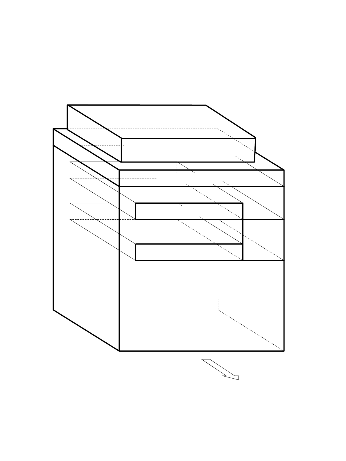
[A] Front co v er/Front side right inner cover
(1) Open the front cov er.
(2) Pull out 2 L-shaped pins and take off the front
cover.
L-shaped
pin
Front cover
(3) Remove 2 screws and take off the front side
right inner cover .
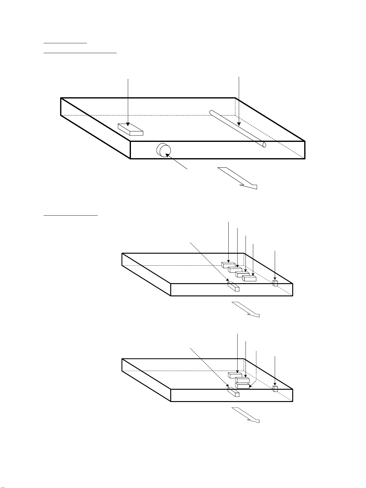
[B] Feed side rear cov er/Feed side top cover/
Feed side center cov er
(1) Remov e 1 scre w and take off the feed side
rear cover.
(2) Remove 2 screws and take off the feed side
top cover.
(3) Open the bypass unit tr a y and remo ve 2
screws. Then remo ve 6 screws and take off
the feed side center cov er.
Front side right inner cover
Feed side
top cover
Feed side
center cover
Feed side
rear cover
[C] Exit side top cover/Exit side rear cover/
Exit side bottom cover
(1) Remove 2 screws and take off the exit side
Exit side
rear cover
Exit side
top cover
top cover.
(2) Remove 1 screw and take off the exit side
rear cover.
(3) Remove 6 screws and take off the exit side
bottom cover.
Exit side
bottom cover
JUNE 2002 © TOSHIBA TEC 2 - 27 e-STUDIO550/650/810 OUTLINE OF THE MACHINE

[D] Rear cover
(1) Loosen 1 screw (sho wn by a white arrow),
remove 6 scre ws, release 2 hooks and take
off the rear cover.
Hook
[E] Right top cover
(1) Remov e 1 screw and take off the right top
cover.
[F] Left top cover
(1) Remov e 1 screw and take off the left top
cover.
Right top cover
Left top cover
e-STUDIO550/650/810 OUTLINE OF THE MACHINE 2 - 28 JUNE 2002 © TOSHIBA TEC

2. 6. 2. PC boards
[A] System control board (SYS board)/Hard disk/
Logic board (LGC board)
(1) Remove the rear co ver.
(2) Disconnect 1 connector .
(3) Remov e 2 scre ws (shown by 2 white arrows),
loosen 14 screws and take off the rear feed
side inner cover (plate co v er).
(4) Remove 1 screw (shown by a white arrow),
loosen 8 screws and take off the rear e xit
side inner cover (plate co v er).
(5) Disconnect 7 connectors, remov e 6 screws
and take off the SYS board.
(6) Disconnect 2 connectors, remov e 4 screws
and take off the hard disk with the brac k et.
(7) Remove 4 screws and release the hard disk
from the bracket.
Rear feed side
inner cover
SYS board Hard disk bracket
Rear exit side
inner cover
(8) Disconnect 19 connectors, remove 6 screws
and take off the LGC board.
[B] High-voltage transformer
(1) Disconnect 7 connectors to the SYS board
and hard disk.
(2) Remove 9 screws and take off the brack et
with the LGC board and hard disk.
LGC board
SYS board
Hard disk
JUNE 2002 © TOSHIBA TEC 2 - 29 e-STUDIO550/650/810 OUTLINE OF THE MACHINE

(3) Disconnect 19 connectors to the LGC board.
(4) Remov e 6 screws and take off the bracket
with the LGC board.
LGC board
(5) Disconnect 6 connectors, remov e 1 screw ,
release 3 lock supports and take off the highvoltage transf ormer.
[C] Po wer supply unit
(1) Remov e the SYS board, hard disk and LGC
board with the bracket.
(2) Remov e 4 screws and take off the bracket of
the power supply unit.
High-voltage transformer
Lock support
(3) Disconnect 1 link connector .
(4) Remov e 9 connectors and pull out the po wer
supply unit.
Note: Be careful not for the power supply unit to be
caught by harnesses.
Link connector (3)
e-STUDIO550/650/810 OUTLINE OF THE MACHINE 2 - 30 JUNE 2002 © TOSHIBA TEC

3. COPY PROCESS
3. 1. General Description
3. 2. Details of Copy Process
3. 3. Comparison of Copy Process to 6570/5570

3. COPY PROCESS
3. 1. General Description
Image processing
10
9
8
Discharging
Original exposure
2 3
Xenon lamp
29W
1
-733V (grid voltage)
Discharging
LED array (wavelength 660nm x 16)
Blade cleaning
Fur brush cleaning
7
Fusing
Fuser roller
700~1450W
Charging
–
–
–
–
Scanning
CCD
600dpi, 7500pixel
–
–
–
–
– –
++++
–
–
–
–
Transfer/Separation
80µA
4
Writing
Semiconductor laser
Pw=3.8nJ/mm
2
Toner
Carrier
–
–
+
–
++
+
–
+
–
++
+
–
–
–
Bias -500VDC+AC
5
Development
Magnetic roller
Bypass feeding
6
Cassette feeding
(1) Charging: Negatively charges the surface of the
photoconductive drum.
훹
(2 ) Original exposure: Converts images into optical
signals.
훹
(3) Scanning: Converts image optical signals into
electrical signals.
훹
(4 ) Writing: Conv erts image electrical signals into
optical signals (laser emission) and exposes
them to the surface of the photoconductive drum.
훹
(5) Development: Makes the negatively-charged
toner adhere to the photoconductive drum and
forms a visible image.
훹
Cleaning brush + Blade
LCF feeding
5µA
(6) Transfer: Transfers the visible image on the
photoconductive drum onto a paper .
Separation: Separates the paper from the drum
together with the toner.
훹
(7) Fusing: Fuses the toner on the paper by applying
heat and pressure.
훹
(8 ) Fur brush cleaning: Cleans dirt and paper dust
on the drum.
훹
(9 ) Blade cleaning: Forcibly removes the residual
toner on the drum.
훹
(10) Discharging: Discharges any remaining
negative charge on the drum.
JUNE 2002 © TOSHIBA TEC 3 - 1 e-STUDIO550/650/810 COPY PROCESS

3. 2. Details of Copy Process
(1) Photoconductive drum
The photoconductive drum has two layers, an outer
and an inner lay er. The outer la yer is a photoconductive
layer made of an organic photoconductive carrier
(OPC). The inner layer is an aluminum conductive
base in a cylindrical form.
The photoconductive carrier has the characteristic
that its electrical resistance changes depending on
the strength of the light exposed.
Example:
· Strong light촞
Resistance is decreased (works as a conductor.)
· Weak light촞
Resistance is increased (works as an insulator.)
[Formation of electrostatic latent image]
In the processes of charging, scanning, printing and
discharging described below , negative potential on
the areas of the drum corresponding to black areas
of the original is eliminated, while the areas of the
drum corresponding to white areas remains the
negative charge.
As this image on the drum formed by the negative
potential is invisible, it is called an “electrostatic latent image.”
Photoconductive layer
Aluminum conductive base
Structure of the photoconductive drum (OPC)
Time (t)
0
– 500
Black area of original
Surface potential (V)
Discharging
process
– 1000
Charging
process
White area of original
Electric potential on the photoconductive drum
Main charger
(2) Charging
Charging is a process of uniformly applying a charge
uniformly to the photoconductive drum surface.
The charger wire produces a negative corona dis-
Rotation of drum
charge, which is controlled by the grid so that the
drum surface is uniformly charged with negative potential.
The surface potential on the drum is determined by
the grid potential and controlled to a certain value
by the grid control circuit.
e-STUDIO550/650/810 COPY PROCESS 3 - 2 JUNE 2002 © TOSHIBA TEC
Discharge
transformer
Grid control circuit

(3) Scanning
Scanning is a process of exposing the original to
the light and converting the reflection into electrical
signals.
The light reflected from the original is impor ted to
the charge coupled device (CCD) and this optical
image information is converted into electrical signals (image signals), which are then sent to the
image processing section.
CCD
Image processing
section
(Example)
(4) Writing
Writing is a process of converting the image signals
sent from the image processing section into optical
signals and exposing the drum surface to the light.
Semiconductor laser element converts image signals sent from the image processing section into
optical signals (laser emission) and exposes the
drum surface to the light to form an electrostatic
latent image on it.
CCD light
receiving
amount
Light
쩪
쩪
Dark 0
Image
processing
section
Polygonal mirror
Photo-
conductive
drum
V alue of
image signals
to be output
255
Difference between
"light " and "dark" is
divided into 256
steps.
Laser Drive
board
Semiconductor
laser element
JUNE 2002 © TOSHIBA TEC 3 - 3 e-STUDIO550/650/810 COPY PROCESS

(5) Development
Development is a process of making the electrostatic latent images visible to the eye (visible images).
Developer material is supplied to the photoconductive drum surface by magnetic roller. The toner in
the developer material adheres to the areas on the
drum surface where the potential is lower than the
developer bias which is applied to the magnetic roller
(reverse development method).
Magnet
Magnetic roller
Bias voltage
–500 VDC
Photoconductive
drum
Toner
Carrier (always attracted
onto the magnet)
Toner
The (–) potential
of the drum being
higher than the
developer bias
The (–) potential
Toner
of the drum being
lower than the
developer bias
Photoconductive layer
Aluminum conductive
base
Dru m Magnetic roller
White background Half tone Solid
– 700V
– 600V
– 500V
– 400V
– 300V
– 200V
– 100V
White background
0
Image not developed
Image is developed by
toner
Bias
potential
e-STUDIO550/650/810 COPY PROCESS 3 - 4 JUNE 2002 © TOSHIBA TEC

• Developer material
The developer material is a mixture of toner and
carrier. The toner is charged to negative polarity and
the carrier to positive polarity , due to the friction with
each other caused by mixing.
Toner :Mainly consists of resin and carbon.
Carrier : Consists of ferrite and resin coating on its
surface to provide consistent frictional electrification.
Resin (90~95%)
[Toner]
Carbon
(5~10%)
5~20µm
Ferrite
30~100µm
[Carrier]
Note:
If the developer material is used for a long time (beyond its normal life span),
the toner is caked onto the carrier.
훹
The carrier’s (charging) performance is lowered.
Symptom: 1. Image density is decreased.
2. Toner scattering occurs.
3. Background fogging occurs.
Solution: Replace new developer material.
• Magnetic roller
- Magnetic brush development The south and north poles are arranged inside the
magnetic rollers, as shown in the right figure. The
developer material forms a brush-like fluff which contacts the photoconductive drum surface.
훹
This is caused by the lines of magnetic force between the south and north poles.
No frictional electrification
on the area where the toner
is caked on
Photoconductive
drum
Toner
Lines of
magnetic force
Carrier
S
N
S
Magnetic roller
JUNE 2002 © TOSHIBA TEC 3 - 5 e-STUDIO550/650/810 COPY PROCESS

Additional Explanation
The life of the toner cartridge (number of copies) varies depending on the following conditions.
1. Coverage of originals (printing image ratio of the original size) and density of original background
2. Size and density of originals
3. The existence of solid black when making copies (when a book is copied and the original cover is
partially open)
4. Temperature and humidity in the room when making copies
5. Copy density and image quality mode
As indicated in the figure below , the life of the toner cartridge varies depending on the copy mode and
coverage of originals
74,000
70,000
60,000
50,000
40,000
30,000
20,000
A
46,000
40,000
30,000
20,000
A
27,000
20,000
B
15,000
C
38,000
30,000
20,000
A
Type of originals
A.
B.
C.
e-STUDIO550/650/810 COPY PROCESS 3 - 6 JUNE 2002 © TOSHIBA TEC

(6) T ransfer/Separation
Transfer:
Transfer is a process of transfering the toner image
(visible image) formed on the drum surface onto the
paper.
An electric charge applied by the high voltage power
supply flows to the transfer belt from the power
supply roller. Then it flows to the paper and photo
conductor. The toner, which has been developed
on the photo conductor, is transfered to this paper
with an electric charge.
Separation:
The paper is absorbed to the belt and separated
from the drum by the electrostatic attraction acting
between the belt (plus charge) and the polarization
charge (minus charge) on the bottom surface of the
paper.
Toner
Drum
Transfer
belt
Paper
Drum
Aluminum conductive base
Photoconductive layer
E
Paper
Transfer belt
Reference
Combined use of transfer belt and
•
separation finger
To prevent the copy paper from failing to
be separated during the operation, due to
incomplete transfer belt charging or
absorption of moisture, and thus jamming
up the cleaner, a separation finger
mechanically separates any copy paper
which fails to be separated.
Power supply roller
Separation finger
Rotation of drum
Paper movement
Transfer belt
JUNE 2002 © TOSHIBA TEC 3 - 7 e-STUDIO550/650/810 COPY PROCESS

(7) Fusing
Fusing is a process of melting and fixing the toner
on the paper.
Method : The melting point of the toner (main
ingredient: resin) is 100~110°C.
훹
(Heat) The toner is melted by the heat of the
surface of the fuser roller .
+
(Pressure) The pressure roller is pressed against
the fuser roller by the springs to increase
adherence of the melted toner to the
paper.
훹
Heat and pressure are applied to the
paper when it passes between the fuser
roller and pressure roller.
||
(Fusing) The toner is fixed on the paper.
Fuser roller
Paper
Pressure
IH coil Fuser roller
Separation finger
Paper mov ement
Pressure
(8) Cleaning
Cleaning is a process of recovering the residual toner
on the photoconductive drum.
1. The cleaning brush scrapes off the excessive
toner and paper wastes. The flicker scrapes off
the toner on the brush.
Also, too pervent the cleaning b lade from
scratching the surface of the drum to make a
circumferential streak, the varistor is attached
between the brush and earth.
2. Cleaning blade scrapes off the residual toner on
the drum.
3. The reco very blade pic ks up the scraped toner .
Pressure roller
Cleaning blade
Drum rotation
Cleaning brush
Flicker
Recovery blade
e-STUDIO550/650/810 COPY PROCESS 3 - 8 JUNE 2002 © TOSHIBA TEC

(9) Discharging
Discharging is a process of eliminating the (–) charge
remaining on the photoconductive drum before the
next charging process begins.
If discharging does not occur, the following
phenomenon will occur:
The (–) charge remains on the photoconductive
drum.
훹
Uneven charge is applied to the drum during the
next copy.
훹
The next copy has a double image. (Preceding image
appears.)
Solution :
Expose the entire surface of the photoconductive
drum to the light by the discharge LED array.
훹
The photoconductive drum becomes electrically
conductive.
훹
All the (–) charges remaining on the photoconductive
drum are conducted to the ground.
훹
The preparation for the next copy is completed.
Dischage LED array
Drum
JUNE 2002 © TOSHIBA TEC 3 - 9 e-STUDIO550/650/810 COPY PROCESS

3. 3. Comparison of Copy Process to 6570/5570
Process
1. Photoconductive drum
(1) Sensitivity
(2) Surface potential
2. Charging
OD-6570 (OPC drum) OD-6510 (OPC drum)
Highly sensitized drum Same as 6570/5570
–650 V (grid voltage –720V) –700 V (grid voltage –733V)
Scolotron method (constant current) Same as 6570/5570
6570/5570 e-STUDIO550/650/810
Grid output variable Same as 6570/5570
3. Surface potential controlling
Non e Surface potential sensor
4. Writing
(1) Light source Semiconductor laser (adjustment Same as 6570/5570
not required)
(2) Light amount 4.0 nJ/mm
2
3.8nJ/mm
2
5. Image density control Image quality sensor Same as 6570/5570
6. Development
(1) Magnetic roller Two magnetic rollers Same as 6570/5570
(2) Auto-toner Magnetic bridge-circuit method Same as 6570/5570
(3) Toner supply Toner hopper system Toner cartridge system
(There is a toner recycle system.)
(4) Toner-empty detection Density detection method/lever joint Density detection system
use
(5) Toner T-6570/6570E T-6510/6510E/6510D
(6) Developer material D-6570J D-6510
(7) Developer bias DC-400V + AC DC-500V + AC
7. Transfer
(1) Transfer Transfer belt Transfer belt
(Electrical resistance is lower than
6570/5570.)
(2) Power supply roller Power supply roller Power supply roller
Separation auxiliary roller Separation auxiliary roller
8. Separation Transfer belt charging Same as 6570/5570
Separation finger applied Same as 6570/5570
9. Discharging
(1) Discharging position Discharge by exposure after cleaning Same as 6570/5570
(2) Discharge lamp Discharge by red LED Same as 6570/5570
(3) Pre-cleaning discharge N one Same as 6570/5570
10. Cleaning
(1) System Blade + Brush Same as 6570/5570
(2) Recovered toner Not acceptable Reuse (by the toner recycle system)
11. Cleaning brush bias Earth Varistor 430V
e-STUDIO550/650/810 COPY PROCESS 3 - 10 JUNE 2002 © TOSHIBA TEC

Process 6570/5570 e-STUDIO550/650/810
12. Fusing
(1) System Long-life heat roller system Same as 6570/5570
· Fuser roller: · Fuser roller:
Fluoroplastic-coated roller (ø60) Fluoroplastic-coated roller (ø60)
· Pressure roller: · Pressure roller:
PFA tube roller (ø60) PFA tube roller (ø60)
(2) Cleaning · Fuser roller cleaning roller (ø33) · Cleaning web (for fuser roller cleaning)
· Cleaning felt roller (ø27)
· Pressure roller cleaning felt roller (ø28) · Pressure roller cleaning felt roller
· Cleaning metal roller · Pressure roller cleaning metal roller
(3) Heater Halogen lamp (Lamp system) IH coil (Induction heating system)
(Lamp rating: 800W + 300W)
ON/OFF control by thermistor Same as 6570/5570
JUNE 2002 © TOSHIBA TEC 3 - 11 e-STUDIO550/650/810 COPY PROCESS

4. GENERAL OPERATION
4. 1 . Overview of Operation
4. 2. Operation
4. 2. 1. Warming-up
4. 2. 2. Standby state (ready for copying)
4. 2. 3. Cassette feed copying with [ST ART] key ON
4. 2. 4. Bypass copying
4. 2. 5. Interrupt copying
4. 3. Abnormality Detection
4. 3. 1. Abnormality classification
4. 3. 2. Abnormality description
4. 4. Flow Chart
4. 4. 1 . Power ON to ready
4. 4. 2. Automatic feed copying

4. GENERAL OPERATION
4. 1. Overview of Operation
Copier operation Operation during warming-up, pre-running and standby
Automatic f eed copying by pressing [ST AR T] key
Copying operation Bypass copying
Interrupt copying
4. 2. Operation
4. 2. 1. Warming-up
(1) Initialization
• Power turned ON
• IH coil turned ON
• Set number “1” and “WAIT W ARMING UP” displayed
• Fan motors turned ON
• Scanning section initialization
~Carriage moving to home position and stopping there
~Carriage moving to peak detection position
~Exposure lamp turned ON ~ P eak detection (White color is detected b y the shading correction plate.)
~ Exposure lamp turned OFF
~Carriage moving to home position
• Feed unit initialization
~Each cassette tray going up
• Writng section initialization
~Polygonal motor rotating
~Beam position controlled
• Other
~Main charger cleaner operating
(2) Pre-running operation
Pre-running operation is started when the temperature of the fuser roller reaches a certain temperature.
(Pre-running is not carried out when the fuser roller has been already hot enough.)
• Fuser roller rotating
• Drum rotating
~Drum motor, used toner transport motor turned ON
• Image quality control
~Patch formed on drum and its reflective ratio read out to set an optimal condition.
(3 ) When fuser roller temperature becomes sufficient for fusing:
• IH coil turned OFF
• Set number “1” and “READ Y” displayed
JUNE 2002 © TOSHIBA TEC 4 - 1 e-STUDIO550/650/810 GENERAL OPERATION

4. 2. 2. Standby state (ready for copying)
• Keys on control panel enab led
• When no key is pressed f or a certain period of time:
~ Set number “1” and reproduction ratio “100%” displayed and copier returning to normal standby
state
4. 2. 3. Cassette feed copying with [START] key ON
(1) [START] key ON
• “READ Y” displa y changed to “COPYING”
• Main charger, de veloper bias and discharge lamp turned ON/Each fan rotating at a high speed
• Drum, transfer belt, fuser unit and developer unit rotating
(2 ) Cassette paper feeding
• Feed motor and feed clutch turned ON
~ Pickup roller, feed roller and tr ansport roller rotating
• Paper reaching transport roller
~Cassette transport sensor turned ON
• Feed clutch turned OFF after a certain period of time
• Paper reaching registration roller
~Registration sensor turned ON and aligning performed
• Feed motor stopping after a certain period of time
(3) Carriage operation
• Exposure lamp turned ON → White shading compensation is carried out.
• Scanning motor turned ON → Carriages 1 and 2 start to advance.
• Copier entering toner supply operation with developer material toner density being lower than pre-set
value
(4 ) In a certain time after carriage operation:
• Registration motor turned ON → Paper is sent to the transfer section.
• Copies counted
(5 ) In a certain time after registration motor is turned ON:
• T ransf er charger ON
(6 ) Carriage scanning termination
• Scanning motor turned OFF
• Exposure lamp turned OFF
• Registration motor turned OFF (after paper trailing edge has passed registration sensor)
e-STUDIO550/650/810 GENERAL OPERATION 4 - 2 JUNE 2002 © TOSHIBA TEC

(7) Paper discharging
• Exit sensor detecting passing of paper trailing edge
• Main charger, dev eloper bias and discharge lamp turned OFF
• Each operation of drum, transfer belt, fuser unit and developer unit stopping and each fan returning
to standby mode rotation
• “READY” displa yed and copier entering standby mode
JUNE 2002 © TOSHIBA TEC 4 - 3 e-STUDIO550/650/810 GENERAL OPERATION

0
22
536
1365
1423
1906
236
1365
250
3680
220
830
260 830
890
1790
1280
1830
1270
1780
260
3240
3330
430
260 4040
2980
2470
Timing chart for copying one A4 sized sheet fed from the 1st cassette
(ms)
Forward rotation
Reverse rotation
Scanner motor
Exposure lamp
Drum motor
1st cassette feed clutch
1st cassette feed sensor
Registration sensor
Registration motor
MVDEN signal
Main charger
Developer bias
Discharge lamp
Exit sensor
e-STUDIO550/650/810 GENERAL OPERATION 4 - 4 JUNE 2002 © TOSHIBA TEC

4. 2. 4. Bypass copying
(1) Paper inserted into bypass feed tra y.
• SFB feed sensor turned ON
~ “READY FOR BYPASS FEEDING” displa y ed
(2) [START] key pressed
• “READY FOR BYPASS FEEDING” displa y changed to “COPYING”
• Main charger, de veloper bias and discharge lamp turned ON/Each fan rotating at a high speed
• Drum, developer unit, transfer belt, and fuser roller rotating
(3 ) Sheet-bypass feeding
• Bypass pickup solenoid turned ON and feed motor rotating in reverse
~ Bypass pickup roller lowered
• Bypass feed clutch turned ON
~ Bypass feed roller, paper f eed roller , and separation roller rotating
• Aligning operation
• Paper reaching registration roller
• Bypass pickup solenoid, feed motor and bypass feed clutch turned OFF in a certain period of
time later
(4 ) Same operations as (3) through (6) of cassette feed cop ying with [START] k ey ON carried out
4. 2. 5. Interrupt copying
(1 ) [INTERRUPT] key pressed
• Interruption lamp turned ON
• Copying operation temporarily halted and carriages-1 and -2 returning to their home position
• “JOB INTERRUPTED JOB 1 SA VED” displa y ed
• Copying mode set to automatic density and 1-to-1 reproduction ratio and copy quantity indicator
unchanged
(2 ) Preferred copying modes specified
(3 ) After an interrupt copying is terminated:
• “PRESS INTERRUPT T O RESUME JOB 1” displayed
• Interruption lamp turned OFF/Copier returning to conditions before interruption when [INTERRUPT]
key is pressed again
• “READY TO RESUME JOB 1” displa yed
(4) [START] key pressed
• Back to copying operation before interruption
JUNE 2002 © TOSHIBA TEC 4 - 5 e-STUDIO550/650/810 GENERAL OPERATION

4. 3. Abnormality Detection
When an abnormality occurs in the copier, a symbol corresponding to the type of the abnormality is
displayed to dr aw the operater’s attention.
4. 3. 1. Abnormality classification
A) Abnormalities which can be cleared without resetting the door switch
(1) Add paper
(2 ) Paper misf eed in bypass
(3) Set key copy counter
B) Abnormalities which cannot be cleared without resetting the door switch.
(1 ) Misfeed in copier
(2 ) Developer unit not installed properly
(3 ) Add toner
C ) Abnormalities which cannot be cleared without turning OFF the main switch
(1 ) Call for service
4. 3. 2. Abnormality description
A-1) Add paper
Empty sensor detects the presence or absence of paper.
[When cassette is not installed]
No Cassette detected
훹
Tray not going up (empty sensor OFF)
훹
“Add paper” displayed
훹
[START] key disabled
[When cassette is installed]
Cassette detected
훹
Tray going up (empty sensor OFF)
훹
“Add paper” displayed
훹
[START] key disabled
e-STUDIO550/650/810 GENERAL OPERATION 4 - 6 JUNE 2002 © TOSHIBA TEC

• When power is turned ON or feed unit initializing is operated:
↓
Presence or absence of paper detected
Tray motor ON ~ Tray going up
When tray-up sensor is not turned ON within a certain period of time:
T ra y being abnormal “Add paper” displayed regardless of paper being present
↓
or not
↔
Turn ON and OFF the power to clear this condition.
When tray-up sensor is turned ON within a certain period of time:
~ Tray motor stopping
At this time, if empty sensor is ON ~ Determined there is a paper
if empty sensor is OFF ~ Determined there is no paper
↓
“Add paper” display blinked
• When the remaining sheets of paper are getting short during copying:
→Tray-up sensor turned OFF → Tray-up motor turned ON ~ Tray going up
→Tray-up sensor turned ON → Tray motor stopping
• When empty sensor is turned OFF despite tray-up sensor being ON during copying:
↓
Determined there is no paper
↓
“Add paper” display blinked
↓
Copying stopped
JUNE 2002 © TOSHIBA TEC 4 - 7 e-STUDIO550/650/810 GENERAL OPERATION

A-2) Bypass misfeed ( )
• When doing a bypass feeding:
Bypass feed pickup solenoid turned ON
↓
Registration sensor turned ON
* When the registration sensor is not turned ON after a certain period of time (E12):
↓
Bypass misfeeding
↓
“Clear paper” symbol ( ) displayed
↓
Copying operation disabled
Solution: Remove paper from the bypass tray, and the bypass sensor will be turned OFF.
A-3) Set key copy counter
• When the key copy counter (optional) is pulled out from the copier which installs it:
“Set key copy counter” displayed
↓
Copying operation disabled
• When the counter is pulled out during copying:
Copying is stopped when the key copy counter is pulled out.
e-STUDIO550/650/810 GENERAL OPERATION 4 - 8 JUNE 2002 © TOSHIBA TEC

B-1) Misfeed in copier ( )
• Paper leading edge jam detected by e xit sensor
Registration motor turned ON
↓
Exit sensor not turned ON within 0.975 sec.
↓
“Clear paper” symbol ( ) displayed (E01)
↓
Copying stopped
Registration
motor
Exit sensor
Timer
ON
ON
0
0.975sec.
• Paper trailing edge jam deteced by exit sensor
Registration motor OFF
↓
Exit sensor not turned OFF within 0.952 sec.
↓
“Clear paper” symbol ( ) displayed (E02)
↓
Copying stopped
• Immediately after power is turned ON:
↓
Any of all sensors at transport path detecting paper (ON)
↓
“Clear paper” symbol ( ) displayed (E03)
• Front cover opened during copying
↓
“Clear paper” symbol ( ) displayed (E41)
Registration
motor
Exit sensor
Timer
Misfeed in copier (E01)
OFF
ON
0
Misfeed in copier (E02)
0.952sec.
• Paper leading edge jam detected by registration sensor
Registration sensor not turned ON within a certain period of time after paper leading edge has
passed transport roller
↓
“Clear paper” symbol ( ) displayed (E20, 22, 25, 30, 34, 3C)
• When a sheet of paper is fed at reverse section:
Registration sensor not turned ON within a certain period of time after reverse motor has been
turned ON
↓
“Clear paper” symbol ( ) displayed (E11)
JUNE 2002 © TOSHIBA TEC 4 - 9 e-STUDIO550/650/810 GENERAL OPERATION

• When a sheet of reversed paper is transported:
Transport sensor 1 not detecting paper in a certain timing
↓
“Clear paper” symbol ( ) displayed (E51, 52, 53, 54)
• When a sheet of paper is fed:
Feed sensor not turned ON after feed clutch has been turned ON
↓
“Clear paper” ( ) symbol display ed (E13, 14, 15, 16, 18, 19: Error codes change depending
on the cassette used.)
B-2 ) Add toner ( )
Toner density lowered
↓
Toner empty detected: Auto toner sensor
↓
Control circuit “Replace toner cartridge” symbol ( ) displayed: Cop ying cannot be started.
↓
Solution: Open the front cover and replace the toner cartridge.
Toner supply operation: copying can be started.
B-3) Replace toner bag ( )
Toner bag becoming full with used toner
↓
Used toner transport auger moving to feed side: Toner bag full detection sensor ON
↓
“Replace toner bag” symbol ( ) displayed
• T oner bag full detection sensor turned ON during copying
↓
Copying stopped after the last sheet copied has been discharged
Solution: Replace to a new toner bag by a service technician.
B-4 ) Developer unit not installed properly
Developer unit desconnected
↓
“Developer unit not installed properly” displayed
Solution: Connect the de v eloper unit connector and close the front cov er .
C-1) Call for service
When the [CLEAR] and “8” keys are pressed simultaneously when the “Call for service” symbol is
blinking, an error code appears on the message display.
For the contents of the error codes, ref er to the “SER VICE HANDBOOK”.
e-STUDIO550/650/810 GENERAL OPERATION 4 - 10 JUNE 2002 © TOSHIBA TEC

4. 4. Flowchart
4. 4. 1. Power ON to ready
Restart
Main SW ON
DC power supply ON
YES
Is cover opened?
NO
IH coil ON
· Scanner motor ON
· Cassette tray-up
motor ON
Is registration
sensor ON?
NO
Is exit sensor ON?
NO
(Start initializing)
YES
YES
Is transport
YES
sensor 1 ON?
NO
A
JUNE 2002 © TOSHIBA TEC 4 - 11 e-STUDIO550/650/810 GENERAL OPERATION
Jam
"E03"

A
Polygonal motor rotating
Scanning section initialization
NO
Is
toner full detection
sensor ON?
NO
Is toner empty?
YES
Toner supply
Is initialization
finished?
YES
YES
NO
NO
Drum motor ON
for 6 sec.
Is
toner full detection
sensor ON?
Have
20sec. passed after
initialization started?
YES
Call for service
(used toner full clear operation)
YES
T oner bag replacement
NO
Is
fuser roller temperature
high enough to start
pre-running?
YES
Pre-running started
Is
fuser roller temperature
high enough to
be ready?
YES
Pre-running finished
Ready
"C26"
NO
Is thermistor
cut down?
YES
NO NO NO
Is heater
cut down?
YES
Is
polygonal motor
NG?
YES
Call for service Call for service Call for service
"C41" "C44" "CA1"
e-STUDIO550/650/810 GENERAL OPERATION 4 - 12 JUNE 2002 © TOSHIBA TEC

4. 4. 2. Automatic feed copying
Press [START] key
Developer bias ON Fuser motor ON
Main charger ON Developer unit motor ON
Discharge lamp ON T ransfer belt motor ON
Drum motor ON Used toner transport motor ON
Recycle toner transport motor ON
Process system
control
Is
polygonal motor
ON?
YES
Laser ON
T ransf er belt bias ON
T ransf er belt bias OFF
Transport system
control
NO
Call for service
"CA1"
Intermediate transport
clutch ON
Intermediate transport
clutch OFF
Registration motor ON
Drum separation
finger solenoid ON
Scanning system
control
Exposure lamp ON
Carriege moving
forward
Carriage stopped
Exposure lamp OFF
Drum separation
finger solenoid OFF
NO
Is H-sync OK?
Registration motor
OFF
Carriage moving
Call for service
"CA2"
NO
remaining set number
Laser OFF
Is
0?
YES
YES
NO
remaining set number
Is
fuser unit exit sensor
ON?
Is
0?
YES
NO
YES
backward
Carriage stopped
Scanning system
control finished
Paper jam
"E01"
Process system
control finished
JUNE 2002 © TOSHIBA TEC 4 - 13 e-STUDIO550/650/810 GENERAL OPERATION
B

B
Paper jam
"E02"
NO
Is
fuser unit exit sensor
ON?
YES
Main charger OFF
Discharge lamp OF F
Developer bias OF F
Drum motor OFF
Transfer belt motor OFF
Fuser motor OFF
Developer unit motor OFF
Recycle toner transport motor OFF
Used toner transport motor O FF
Drum reversed
Standby
e-STUDIO550/650/810 GENERAL OPERATION 4 - 14 JUNE 2002 © TOSHIBA TEC

5. CONTROL PANEL
5. 1. Control Panel and Display Panel
5. 2. Items Shown on Display Panel
5. 2. 1. Display during normal copying
5. 2. 2. Display in abnormal condition
5. 3. Relation between Copier State and Operator's Action
5. 4. Operation
5. 4. 1. Dot matrix LCD circuit
5. 4. 2. LED display circuit
5. 5. Disassembly and Replacement

5. CONTROL PANEL
5. 1. Control Panel and Display Panel
The display unit consists of key switches and touch-panel switches to operate the copier and select
various modes, and LEDs and an LCD to display the state of the copier or the messages.
When the operator’s attention is reguired, g raphic symbols appear with messages explaining the condition
of the copier in the LCD panel.
Control Panel Exterior View
JUNE 2002 © T OSHIBA TEC 5 - 1 e-STUDIO550/650/810 CONTROL P ANEL

5. 2. Items Shown on Display Panel
A
C
Fig. 5.2-1
H
I
G
E
J
D
F
E
K
B
Fig. 5.2-2
e-STUDIO550/650/810 CONTROL PANEL 5 - 2 JUNE 2002 © TOSHIBA TEC

5. 2. 1. Display during normal copying
No. Message
1 WAIT W ARMING UP
2 READY(WARMING
UP)
3 READY
4 COPYING
5 Saving energy
- Press [START]
6 Place next original
Press [START] to
copy
7 —
8 READY (PRINTING)
9 READY
(ADD PAPER)
10 READY
(FINISHER FULL)
11 READY
(HOLE PUNCH
DUST FULL)
State of copier
Scanner warming up
- Displayed when the power is turned ON until the copier becomes ready to start scanning.
Ready for scanning
- The copier is ready for scanning and waiting
for operator to select the copying conditions.
- Returns to default setting if no key is
operated within 45 seconds.
Ready for copying
- The copier is ready for copying and waiting for
the operator to select the copying conditions.
- Returns to default setting if no key is operated
within 45 seconds.
The original is being scanned
- Displayed by pressing the [START] key.
The copier is in the energy saver mode.
Ready for the next original
- Displayed by pressing the [Next original;
YES] key.
Pow er is OFF
- Nothing is displayed in the display panel.
- Timer LED is lit.
Ready for scanning
- The copier is ready for scanning and waiting
for the operator to select the copying conditions.
Background printing is in progress.
Ready for scanning
- The copier is ready for scanning and waiting
for the operator to select the copying conditions.
Paper in the cassette has run out during printing.
Ready for scanning
- The copier is ready for scanning and waiting
for the operator to select the copying conditions.
The finisher is full of paper.
Ready for scanning
- The copier is ready for scanning and waiting
for operator to select the copying conditions.
The punching dust box is full.
Note
- The set number “1” and the reproduction ratio “100%” are displayed
when the power is turned ON.
- The set n umber “1” is display ed. Press
the digital key to change the number.
- The number is reset to “1” by pressing
the [CLEAR] key.
- Bypass feed copying is enabled.
- The set n umber “1” is display ed. Press
the digital key to change the number.
- The number is reset to “1” by pressing
the [CLEAR] key.
- Bypass feed copying is enabled.
- After scanning is completed, the copier
becomes ready for the next scanning.
- Can be cleared by pressing the
[START] key, function select key.
- Displayed for SADF and manually
placed originals.
- Press the [START] key or function
select key.
- Since background printing is in
progress, the scanned image is not
output immediately.
- Printing is resumed by adding paper
to the cassette.
- Printing is resumed by removing
paper from the finisher.
- Printing is resumed by removing
punching dust from the dust box.
JUNE 2002 © T OSHIBA TEC 5 - 3 e-STUDIO550/650/810 CONTROL P ANEL

No. Message
12 READY
(SADDLE STITCH
TRAY FULL)
State of copier Note
Ready for scanning
- The copier is ready for scanning and waiting
for the operator to select the copying conditions.
The saddle stitcher is full of paper.
Printing is resumed by removing paper
from the saddle stitcher unit.
13 READY
(SET CORRECT
CASSETTE)
14 READY (ADDING
TONER)
15 READY (CHECK
STAPLER)
16 READY (CHECK
SADDLE STITCH
STAPLER)
17 READY (USE
GENUINE TOSHIBA
TONER)
18 ENTER DEPART-
MENT CODE
19 READY (ADD
INSERTER PAPER)
20 READY (ADD TAB
SHEET)
21 READY (FINISHER
IN USE)
Ready for scanning
- The copier is ready for scanning and waiting
for the operator to select the copying conditions.
Cassette not installed during printing
Ready for scanning
- The copier is ready for scanning and waiting
for the operator to select the copying
conditions.
The receiving tray is full of paper.
Ready for scanning
- The copier is ready for scanning and waiting for
the operator to select the copying conditions.
The finisher unit runs out of the staples.
Ready for scanning
- The copier is ready for scanning and
waiting for the operator to select the
copying conditions.
The saddle stitcher unit runs out of the
staples.
Ready for scanning
- The copier is ready for scanning and
waiting for the operator to select the
copying conditions.
Toner other than Toshiba’s has been used.
The copier is waiting for the operator to
enter the department code.
- Displayed when the department management function has been used
Ready for scanning
- The copier is ready for scanning and
waiting for the operator to select the
copying conditions.
No inserter paper
Ready for scanning
- The copier is ready f or scanning and waiting
for the operator to select the copying
conditions.
No tab paper
Ready for scanning
-The copier is ready for scanning and waiting
for the operator to select the copying
conditions.
Finisher manual operating
- Printing is resumed by changing
the setting for cassette selection,
then pressing the [START] key.
- Printing is resumed automatically
when the toner supply is completed.
- Printing is resumed automatically
when the staple cartridge is
replaced with a new one.
- Printing is resumed automatically
when the staple cartridge is
replaced with a new one.
The display is made to disappear by
using the toner provided by Toshiba.
The copier becomes ready to start
copying when the correct department code is entered.
Printing is resumed when the
[START] key is pressed under the
condition the printing UI is displayed
([JOB STATUS] key pressed) after
adding inserter paper.
Printing is resumed when the [ST AR T]
key is pressed under the condition the
printing UI is displayed ([JOB
STA TUS] key pressed) after adding
tab paper.
Printing is started when pressing the
[START] key.
e-STUDIO550/650/810 CONTROL PANEL 5 - 4 JUNE 2002 © TOSHIBA TEC

5. 2. 2. Display in abnormal condition
No. Message
1 Add paper
2 Add toner
Press [HELP]
3 Set key copy
counter
4 Paper misfeed in
bypass
5 Misfeed in copier
Press [HELP]
6 Misfeed in copier
Press [HELP]
Abnormal state and indication on display panel
Paper run out [Fig.5.2-1 A]
- The cassette with no more paper flashes.
Toner r un out [Fig.5.2-2 B]
- The toner cartridge is empty.
- The message is displayed and the copier is
stopped.
Key copy counter not installed [Fig.5.2-1 C]
- The key copy counter was pulled out when
copier was ready for scanning.
- The copier is stopped when the key copy
counter is pulled out after the [START] key
was pressed.
Bypass paper jam [Fig.5.2-2 D]
- Paper jam at the bypass tray
Paper jam in the copier [Fig.5.2-2 E]
Misfeeding of cassette paper [Fig.5.2-2 F]
- Paper fed from the cassette does not reach
the feed sensor in a fixed time.
Solution
- Add paper to the cassette.
- Select a different cassette.
- Replace the toner cartridge and close
the front door.
- Insert the key copy counter (option).
- Remove the paper from the bypass
tray.
- Press the [HELP] key and remove the
paper following the messages
shown on the display panel.
- Press the [HELP] key and remove the
paper following the messages
shown on the display panel.
7 Misfeed in doc.
feeder
Press [HELP]
8 Misfeed in finisher
Press [HELP]
9 Misfeed in
INSERTER
10 Call for service
11 Time for periodic
maintenance
12 Check paper in LCF
13 —
14 Select the same
sized Tab sheets as
the originals
Original jam [Fig.5.2-2 G]
- Original jamming in RADF
Paper jam in the finisher [Fig.5.2-2 H]
Paper jam in the inserter [Fig.5.2-2 I]
Motors, sensors, switches, etc. do not work
properly. [Fig.5.2-2 J]
PM cycle
- Time for maintenance
- Copying is possible.
Paper misloading in the tandem LCF
- Displayed when a paper is set out of alignment
Toner bag full
- The toner bag is full of used toner.
The copier stops its operation. [Fig.5.2-2 K]
Displayed when the paper sizes for the tab
sheets and originals are different
- Open the jam-access cover and
RADF unit to remove the original.
- Press the [HELP] key and remove the
paper following the messages
shown on the display panel.
- Press the [HELP] key and remove the
paper following the messages
shown on the display panel.
- Turn OFF the power and solve the
problem, then turn ON the power again.
- Maintenance and inspection are performed by a qualified service technician.
- Set the paper correctly.
- Replace the toner bag with a new
one and close the front cover.
- Select the same size for tab sheets
and originals.
JUNE 2002 © T OSHIBA TEC 5 - 5 e-STUDIO550/650/810 CONTROL P ANEL

No. Message
15 Select the same
sized Inserter sheets
as the originals
Abnormal state and indication on display panel Solution
Displayed when the paper sizes for
inserter paper and original are different
- Select the same size for the inserter
sheets and originals.
16 Set Tab sheets in the
same direction as
the originals
17 Set Inserter sheets in
the same direction as
the originals
18 Only one paper
source can be used
with Cover Sheet
feature.
19 Only two paper
sources can be used
with Sheet Insertion
feature.
20 ADD PAPER TO
INSERTER FEEDER
21 Set the paper source
for T ab sheet
22 Cannot use OHP
Displayed when the paper directions for
tab paper and original are different
Displayed when the paper directions for
inserter paper and original are different
Displayed when both the cover mode and
inserter cover mode are selected
Displayed when all the sheet insertion
mode, tab insertion mode and inserter
sheet insertion mode are selected
Displayed when the inserter mode is valid
and the [START] key is pressed without
papers on the tray
Displayed when the tab paper mode is valid
and the tab cassette is not selected
Displayed when the paper is OHP and
duplex printing is carried out
- Set the tab sheets in the same
direction as the originals.
- Set the inserter sheets in the same
direction as the originals.
- Release either the cover mode or
inserter cover mode.
- Release any of three modes
- Release the inserter mode
- Set papers on the inserter tray
- Select the 2nd cassette property to
the tab to release this state.
- The display is released when
either the setting for OHP or for
dupulex printing is released.
23 Wait Saving f orm
24 Fuser cleaning web
decreased
25 Time for periodic
maintenance (Fuser
cleaning web)
26 Tab size: A4/LT only
27 Please divide and set
the documents which
is loading over
28 Service
recommended for
SPC
Displayed during inputting the form
combination original
Displayed when the fuser unit cleaning
web gets decreased
* This message is set not to be displayed
at shipment, but the setting can be
changed at the setting mode (08-938).
Displayed when the fuser unit cleaning
web gets run out
Displayed when the tab paper mode is
valid and other than A4/LT is selected for
the tab paper size
Displayed when originals on the RADF are
loading over
Displayed when the surface potential
control error occurs
- The display is released when the
saving has finished.
- Replace the cleaning web.
- Replace the cleaning web.
- Select A4 or LT for tab paper.
- Remove originals from RADF.
- The condition is released when the
surface potential control has
finished normally.
e-STUDIO550/650/810 CONTROL PANEL 5 - 6 JUNE 2002 © TOSHIBA TEC

5. 3. Relation between Copier State and Operator’s Action
-
-
STOP
JOB ST A TUS
-
-
--
-
--
---
Function select
Bypass Touch
ENERGY SA VER
--
INTERRUPT
-
--
--
-
--
-------
----
----
Operation START CLEAR Digital Cassette
State of copier key key keys s el e ction key key feeding panel key key key
Scanner warming up
Printer warming up
Ready for copying
Printing
Scanning -
Paper run out
T oner empty
Key cop y counter not inserted -
(optional)
Paper misfeed in bypass copying -----------
Paper jammed inside the machine -----------
Service call indicated -----------
Ready for interrupt copying
In energy saver mode
Power OFF
JUNE 2002 © T OSHIBA TEC 5 - 7 e-STUDIO550/650/810 CONTROL P ANEL
: Operation enabled - : Operation disabled
Manual operating

5. 4. Operation
5. 4. 1. Dot matrix LCD circuit
(1 ) Structure
(320 x 240)
The DSP-LCD-320 is an STN blue mode transmissive type LCD with a 320 x 240-dot display capacity. It
consists of a driver LSI, frame, printed circuit board, and lateral type CFL backlight.
* STN:Super Twisted Nematic
(2 ) Block diagram
XSCL
UD0
UD1
UD2
UD3
IC2
LCD PANEL
IC3 IC4
WF
LP
LCDEN
IC5
IC6
IC1
80 80 80 80
80
80
320 x 240 DOTS
VDD
GND
V0
VEE
e-STUDIO550/650/810 CONTROL PANEL 5 - 8 JUNE 2002 © TOSHIBA TEC
Power
supply
IC7
80

(3 ) LCD drive operation
The following describes the drive operation to displa y the message “READY”.
PWA-F-SYS-300
PWA-F-SYS-340
GA
LCD
controller
(c)
(c)
(d)
System
CPU
R
A
M
(a)
PROM
(b)
(a) The System CPU requests the
PROM data to display “READY”.
(b) The PROM outputs data to display
the message to the System CPU.
(c) The System CPU writes the data to
be displayed on the LCD into the
RAM.
(d ) The LCD controller/driver reads the
display data from the RAM, and outputs the data to the LCD .
LED
driver
(d)
LED
PWA-F-DSP-300
PWA-F-DSP-340, PWA-F-MKEY-340, PWA-F-SKEY-340
LCD
KEY CPU
Key switches
and
touch panel
(4 ) Data transmission
FRAME
240 1 2 240
LOAD
FRAME
12
1/tF1/tF
240
12
LOAD
CP
D0-D3
JUNE 2002 © T OSHIBA TEC 5 - 9 e-STUDIO550/650/810 CONTROL P ANEL
CP x(320/4) pulses

5. 4. 2. LED display circuit
(1 ) Method of LED display
ex) Displaying “COPY”
5VL
LDON0
"L"
Q3
Current
G
(COPY)
LED4
"L" 17
D7
R3
IC8(7932)
The transistor is turned ON when the LDON 0 signal becomes “L” le vel.
Also, when IC8-17pin (D7) changes to “L”, the current flows from 5VL via the transistor to LED4 (“COPY”)
to turn ON LED4 (“COPY”).
Conditions to turn ON the LED
(a ) The transistor (Q3) connected to the LED anode is ON.
(b) The output from the cathode side of the LED is “L” lev el.
The LED is turned ON when (a) and (b) are satisfied.
e-STUDIO550/650/810 CONTROL PANEL 5 - 10 JUNE 2002 © TOSHIBA TEC

5. 5. Disassembly and Replacement
[A] Control panel unit
(1 ) Open the front cover and take off the front side
right inner cover , toner cartridge drive unit and
toner recycle unit.
(2 ) Remove 2 screws and take off the control panel
bottom cover.
Control panel bottom cover
(3 ) Disconnect 3 connecters, remove 2 screws,
release harnesses from 2 clamps and take off
the control panel unit.
(4 ) Remove 10 screws, disconnect 2 connectors
and release the braket after disconnecting 1
connector at the counter.
Clamp
Connector
Connector
(5 ) Disconnect 7 connectors, remove 6 screws and
take off the DSP board.
JUNE 2002 © T OSHIBA TEC 5 - 11 e-STUDIO550/650/810 CONTROL PANEL
Connector
DSP board
Connector
Connector

(6 ) Remove 9 screws and take off the MKEY board.
(7 ) Remove 8 screws and take off the SKEY board.
(8 ) Remove 4 screws and take off the LCD panel.
MKEY board
LCD panel
SKEY board
e-STUDIO550/650/810 CONTROL PANEL 5 - 12 JUNE 2002 © TOSHIBA TEC

6. SCANNING SECTION
6. 1 . Function
6. 2. Construction
6. 3. Operation
6. 3. 1. Scanner motor
6. 3. 2. T wo-phase motor drive circuit (fixed-current type)
6. 4. Control for Exposure Lamp
6. 4. 1. General description
6. 4. 2. Exposure lamp
6. 4. 3 . Control circuit for exposure lamp
6. 5. CCD control
6. 5. 1. Opto-electronic conversion
6. 5. 2. Shading correction
6. 6. Automatic Original Size Detection Circuit
6. 6. 1. Principle of original size detection
6. 6. 2. Process of original size detection
6. 7. Disassembly and Replacement

6. SCANNING SECTION
6. 1. Function
In the scanning section of this copier, the surface of an original is irradiated with a direct light and the
reflected light is led through mirrors and lens to the CCD where the optical-to-electrical conversion is
performed, converting the optical image data into an electrical signal. This analog signal is changed to a
digital signal, and then undertakes various corrective processes necessary for image formation. After that,
an arithmetic operation is performed on the digital signal, which is then sent to the data writing section.
Exposure lamp Carriage-1 Drive pulley
Reflector
Shading correction
plate
Rail for carriage-1 Original glass
Carriage-2
Lens
Rail for carriage-2
CCD sensor
CCD board
SLG board
JUNE 2002 © TOSHIBA TEC 6 - 1 e-STUDIO550/650/810 SCANNING SECTION

6. 2. Construction
The construction and purpose of the scanning system are described in this section.
(1 ) Original glass
This is the glass on which originals to be copied are placed. The light from the e xposure lamp is irradiated
to the original through this glass.
(2) Carriage-1
The carriage-1 consists of the exposure lamp, lamp inverter, reflector, mirror-1, etc. It is driven by the
scanner motor and scans the original on the glass.
a. Exposure lamp
This lamp is the light source to irradiate the original on the glass (one 29W Xenon lamp).
b . Lamp inverter
This inverter controls lighting of the Xenon lamp.
c. Reflector
This is a plate to direct the light from the exposure lamp efficiently to the surface of the original on the
glass.
d. Mirror-1
This is a mirror to direct the reflected light from the original to the mirror-2 that is described later.
Original glass
Exposure lamp
Original
Reflector
Mirror-1
e-STUDIO550/650/810 SCANNING SECTION 6 - 2 JUNE 2002 © TOSHIBA TEC

(3) Carriage-2
The carriage-2 consists of mirror-2, mirror-3, etc. and directs the reflected light from the mirror-1 through
mirrors-2 and -3 to the lens.
This carriage-2 is driven by the scanner motor as the carriage-1, at half the scanning speed of carriage-1
(the scanning distance is also half of carriage-1).
(4 ) Lens unit
The light reflected from mirror-3 is led to the CCD placed at the focal point of the lens which is fixed in
position.
(5) CCD board
Processes such as the signal amplification, signal integration, A/D conversion and shading correction are
applied on the electrical signal which has been converted by the CCD .
(6 ) Automatic original detection sensor
The size of the original placed on the glass is instantly detected using the automatic original detection
sensors (APS sensor) fixed on the base frame without carriage-1 having to move.
JUNE 2002 © TOSHIBA TEC 6 - 3 e-STUDIO550/650/810 SCANNING SECTION

6. 3. Operation
2GT-Z24
6. 3. 1. Scanner motor
Carriage-1Carriage wireScanner motor Pulley for carriage-2
Ø20
Motor pulley
2GT-Z24
Wire pulley
Ø30.83/2GT-Z84
Idler pulley
Ø20
Carriage-2
(a ) Scanning original on original glass
This motor drives the carriages-1 and -2 through the timing belt and carriage wire. The scanner motor
first drives carriages-1 and -2 to their respective home positions. The home positions are detected
when carriage-1 passes the home position sensor. When the [START] key is pressed, both carriages
start to move and scan the original on the glass.
(b ) Scanning original on RADF
Carriage-1 stays at the shading position during the shading correction, and at the scanning position
during the scanning operation.
e-STUDIO550/650/810 SCANNING SECTION 6 - 4 JUNE 2002 © TOSHIBA TEC

6. 3. 2. Two-phase motor drive circuit (fixed-current type)
The scanner motor with the unipolar fixed current chopper method is driven by the stepping motor
driver STK672-080 (IC4).
PG
1
5 4 3 2
Vcc2 Vref A AB B BB
SUB
Switching
current
fraction ratio
Generation
of pseudo
sine wave
Generation of phase
excitation signal
6 7
Excitation
mode setting
9
8
Phase
counter
Switching pulse
ON/OFF detection
11
10
12
13
Excitation
status monitor
14
PWM control
Generation of
reference clock
CR oscillation
15
M2
M1
CWB
JUNE 2002 © TOSHIBA TEC 6 - 5 e-STUDIO550/650/810 SCANNING SECTION
M3
CLOCK
RESET
Mol
ENABLE

PWA-F-SLG
Scanner CPU
SCNREF-0A
SCNEN-0
SCNRST
SCNDIR-0
SCNCLK-0
SCNMD1-0
SCNMD2-0
SCNMD3-0
Motor
driver
J8
1
2
3
4
5
6
SCN-MOT
6
5
4
321
IC9
Input signals
SCNCLK-0 CLK input Input
SCNDIR-0
SCNEN-0
SCNREF-0A
SCNMD1~3-0
SCNRST Reset Input
Sets the direction
of motor rotation
Cuts OFF the
drive output
Voltage to set value
for the motor current
Sets the exicitation
mode (1)–(3)
Input
Input
Input
Input
IC4
+36V
+36V
J9
1
3
2
4
Circuit diagram
The motor is rotated by setting the number of pulses.
* The internal circuit of the motor driver works at the rising and falling
edge of pulse.
The direction of the motor rotation is determined by the setting level
of signal
“H”…Clockwise direction (as seen from the output shaft)
“L”…Counterclockwise direction (as seen from the output shaft)
Note: When SCNMD3-0 is “L”, do not change the rotation direction
within 6.25µs before and after the rising and falling edge of
the pulse of SCNCLK-0.
“H” …Normal operation (The motor has been excited.)
“L”…Excitation drive output is forcibly shut OFF (the motor has not
been excited).
Motor wire current value is set in the range of 0 to 2.25 (A)/phase by
applying the analog voltage 0 to 5 (V).
Sets the excitation mode.
Note: Do not change the setting wihin 5µs before and after the
rising and falling edge of the pulse of SCNCLK-0.
Internal circuit of the driver is initialized by setting the motor to “L”
level (pulse interval: 10µs or more).
The motor drive circuit is automatically reset when the power is
turned ON.
e-STUDIO550/650/810 SCANNING SECTION 6 - 6 JUNE 2002 © TOSHIBA TEC

6. 4. Control for Exposure Lamp
6. 4. 1. General description
Control circuit of the exposure lamp consists of the following 3 blocks.
(1 ) Lighting device for the Xenon lamp (Inv erter)
Turns the exposure lamp ON/OFF.
(2 ) CCD sensor circuit
This circuit works to the convert the reflected light amount from the original surface and the shading
correction plate to the electrical signals. The reflected light amount from the shading correction plate is
read to control the exposure amount.
(3 ) Image processing circuit
The output signals from the CCD are digitized and the image processing such as gamma correction
and shading correction is applied to them.
PWA-CCD
Original
Shading correction plate
Exposure lamp (Xenon lamp)
CCD sensor
PWA-CCD
A/D
Image processing
circuit
Construction of exposure lamp control circuit
Lighting device
for Xenon lamp
(Inverter)
PWA-SLG
Scanner
Main CPU
CPU
IC37
JUNE 2002 © TOSHIBA TEC 6 - 7 e-STUDIO550/650/810 SCANNING SECTION

6. 4. 2. Exposure lamp
External electrode type Xenon fluorescent lamp is used as an exposure lamp in this copier .
(1 ) Structure
The fluorescer is applied to the inside surface of the lamp pipe (except for a part which serves as an
opening) which is filled with the Xenon gas.
A pair of the external electrodes
covered by film with adhesive agent
is attached around the pipe.
PET film
Aluminum tape
electrode
Adhesive agent
Fluorescer
Xenon gas
Glass valve
(2 ) Behavior inside the lamp
The electron inside the pipe is led
to the electric field by applying voltage to the pair of the external electrodes, and the discharge is started.
The electrons then flow and clash
with the Xenon atoms inside the pipe
to excite them and allow them to
generate ultraviolet r ays. This ultraviolet rays con vert the fluorescer into
visible light.
(6)
(5)
(7)
(1)Electrode (2)Electron (3)Xenon atom (4)Ultraviolet ray (5)Fluorescer
(6)Visible light (irradiated from the opening to outside the pipe)
(7)Opening (8)Harness
(2)
(4)
(3)
(1)
(8)
e-STUDIO550/650/810 SCANNING SECTION 6 - 8 JUNE 2002 © TOSHIBA TEC

6. 4. 3. Control circuit for exposure lamp
P24
WDTOUT
P23
EXPON–0
WDTOUT–0
WDTEN–0
HCT00
IC16
+5V
HCT00
IC16
HC14
IC17
HCT00
IC16
D1:1SS184
Q3:RN2401
Scanner
CPU
IC9
PWA–F–SLG–340
Working conditions
EXPON-0
WDTOU T-0 WDTEN-0
(Lamp drive signal)
+5VSW Q2 Xenon lamp State of copier
HH H ON OFF OFF
HH L ON ON ON
LX X OFF OFF OFF
+5VSW
Q2:RN1401
SG
EXPON–0A
Normal operation
Scanner CPU
Xenon lamp
Xenon lamp
lighting device
overdriving
HL X OFF OFF OF F Call for Service
JUNE 2002 © TOSHIBA TEC 6 - 9 e-STUDIO550/650/810 SCANNING SECTION

6. 5. CCD Control
6. 5. 1. Opto-electr onic conversion
A CCD (charge-coupled device) is used to produce an electrical signal corresponding to the reflected light
amount from the original. The CCD is a one-chip opto-electronic con version de vice, comprised of se veral
thousand light-receiving elements arranged in a line; each one of them is a few microns square.
This model is equipped with a CCD which has 7,500 light-receiving elements.
Each element of the light-receiving section consists of the semiconductive lay ers P and N. When the light
irradiates the element, the light energy produces a (-) charge in the layer P; the amount of the charge
produced is proportional to the energy and irradiating time. The charges produced in the light-receiving
section are then sent to the transfer section where they are shifted by the transfer clock from left to right as
shown in the figure below , and are finally output from the CCD . At this time , to increase the transfer speed
of the CCD, image signals in the even-number and odd-number elements are separated and output in
parallel via two channels.
Transfer section
Light receiving
section
Transfer section
1
Shift register
Transfer clock
2
34
7497 7498 7499 7500
Transfer clock
Light energy
layer N
layer P
Details of light receiving element
[Principle of the opto-electronic conver sion by CCD]
6. 5. 2. Shading correction
Signal voltages read by the CCD have the following characteristics.
(1 ) Light source has variation in its light distribution.
(2) Since the light beam reflected from the original is converged using a lens, the light path is the
shortest at the center of the CCD and the longest at ends. This causes difference in the amount of
light reaching the CCD (i.e. the light amount is maximum at the CCD center, gradually decreases
toward ends).
(3 ) Each of the 7,500 elements varies in the opto-electronic conversion efficiency.
These variations need to be corrected and this correction is referred to as shading correction. Based on the
black and white data obtained in advance, a normalization process using the following formula is applied to
the raw image data to correct lighting variance and element variation of the image data.
I = k ×
(S — K)
(W — K)
k : Coefficient
S : Image data before correction
K : Black data (stored in “black” memory)
W : White data (stored in “white” memory)
e-STUDIO550/650/810 SCANNING SECTION 6 - 10 JUNE 2002 © TOSHIBA TEC

6. 6. Automatic Original Size Detection Circuit
This circuit detects the size of original (standard sizes only) using the reflection type photosensors arranged on the base frame of the scanner unit.
6. 6. 1. Principle of original size detection
The reflection type photosensors are placed on the base frame of the scanner unit as shown in the Fig. 6.6-
1. Each sensor consists of an infrared light emitting diode (LED) on the light emitting side, and a phototransistor
on the light receiving side.
When there is an original on the original glass, light beams from the LEDs are reflected by the original and
led to the phototransistors. This means that the size of the original is detected by checking which
phototransistors are turned on or are not.
[A4 Series]
Original
APS-4
Original glass
APS-5
[LT Series]
Original glass
Original
APS-5
APS-4
APS-2 APS-3
APS-1
APS-3APS-2
Fig. 6.6-1
6. 6. 2. Process of original size detection
(1 ) When the copier is in the original size detection mode, the carriage-1 is set at its home position.
(2) When the RADF is opened, the sensors receive the light reflected from the original and if one of the
matrix conditions shown in (4) for original sizes is satisfied, the size of the original is instantly
detected.
(3 ) The output signal from each sensor is input to the CPU on the scanner control PC board to determine
the size of the original.
APS-5
V
DD
33
P81
[LT Ser ies][A4 Series]
APS-5
33
P81
V
DD
32
P80
30
P96
29
P95
28
P94
PWA-SLG
GND
Reflection type
photosensor
APS-4
APS-3
APS-2
30
P80
29
P96
28
P95
PWA-SLG
GND
Reflection type
photosensor
APS-4
APS-3
APS-2
APS-1
Fig. 6.6-2 Original size detection circuit
JUNE 2002 © TOSHIBA TEC 6 - 11 e-STUDIO550/650/810 SCANNING SECTION

[A4 Series]
A5 B5 A4
APS-5
[LT Series]
APS-4
APS-3
APS-1
APS-2
ST LT
A5–R
B5–R
A4–R
B4
A3
APS-4
APS-5
ST–R
APS-3
LT–R
APS-2
LG
LD
Fig.6.6-3 Sensor detection points
e-STUDIO550/650/810 SCANNING SECTION 6 - 12 JUNE 2002 © TOSHIBA TEC

(4 ) Original size is determined by the combination of the presense/absence of signals which are output at
each detection point. The combination chart for size determination of A4 series and LT series are as
followed.
[A4 Series]
Size APS-1 APS-2 APS-3 APS-4 APS-5
A300000
A400001
B400010
B510011
A4-R 0 0 1 1 0
A510111
B5-R 0 1 1 1 0
A5-R 0 1 1 1 1
[LT Ser ies]
Size APS-2 APS-3 APS-4 APS-5
LD 0 0 0 0
LT 0 0 0 1
LG 0 0 1 0
LT-R 0 0 1 1
ST 1 0 1 1
ST-R 0 1 1 1
Code
1 H Absent
0 L Present
* When the APS operation sensor is OFF;
• The following points are determined by the output signals from APS sensors
Size (The combination of the signals satisfy the above chart)
Size retention (The combination of the signals do not satisfy the above chart)
No original (output from all the sensors are “1”.)
• Size change is always observed and detected.
• Carriage-1 stays at the standby position even if the reproduction ratio changes corresponding to the change of
the original size.
* When the APS operation sensor is ON;
Retains the latest original size (or no original state) recognized right before the APS operation sensor is turned
ON regardless of the state of the APS sensor output signals.
Output signal
: Size is displayed on the control panel and an appropriate paper and reproduction ratio are selected.
:Retains the latest original size recognized (or no original state) until a new paper size is recognized.
:Reproduction ratio and paper size are not selected.
Original
JUNE 2002 © TOSHIBA TEC 6 - 13 e-STUDIO550/650/810 SCANNING SECTION

About reflection type photosensor
The reflection type photosensor is comprised of an infrared light emitting diode and a phototransistor . It
uses the pulse modulation to detect an original.
Original
8µsec
130µsec
LED
Phototransistor
The light emitting diode is driven by a pulse having a 130-µsec cycle and an 8-µsec ON time . When the
phototransistor receives the same signal as this pulse, it is determined that there is an original. The
pulse modulation is performed inside the reflection type phototransistor .
e-STUDIO550/650/810 SCANNING SECTION 6 - 14 JUNE 2002 © TOSHIBA TEC

6. 7. Disassembly and Replacement
[A] Original glass
(1) Take off the right top cover.
(2) Remove 2 screws and take off the glass retainer .
(3) Lift the feed side of the original glass and tak e it
off toward the f eed side.
Glass retainer
[B] Lens cover
(1) Remov e the original glass.
(2) Remov e 9 screws and take off the lens cover.
(Disconnect 1 connector of APS sensor at this
time.)
[C] Automatic original detection sensor (APS sensor)
(C-1) A4 series
(1) Remov e the original glass.
(2) T ak e off 4 APS sensors each with disconnecting
1 connector and removing 1 screw.
Lens cover
APS sensor
(3) Remove the lens co ver.
APS sensor
(4) Remove 2 scre ws and take off the APS sensors
with brackets .
(5) Remove 1 scre w and release the APS sensors
from the brack ets.
JUNE 2002 © TOSHIBA TEC 6 - 15 e-STUDIO550/650/810 SCANNING SECTION

(C-2) LT series
(1) Remov e the original glass.
(2) T ak e off 3 APS sensors each with disconnecting
1 connector and removing 1 screw.
(3) Remov e the lens cover.
(4) Remov e 1 screw and tak e off the APS sensors
with brackets .
(5) Remov e 1 screw and release the APS sensors
from the brackets .
APS sensor
[D] SLG fan motor
(1) Remov e the lens cover.
(2) Disconnect 1 connector, remove 2 screws and
take off the SLG fan motor.
[E] Exposure lamp
(1) Move the carriages toward the exit side,
disconnect 1 connector of the exposure lamp
and remove 1 scre w.
SLG fan motor
Connector
e-STUDIO550/650/810 SCANNING SECTION 6 - 16 JUNE 2002 © TOSHIBA TEC
 Loading...