

Page 1

SERVICE HANDBOOK
DIGITAL PLAIN PAPER COPIER
e-STUDIO550/650/810
(DP-5510/6510/8110)
File No.31110201
2002-06
Page 2

Copyright 2002
TOSHIBA TEC CORPORATION
Page 3

GENERAL PRECAUTIONS REGARDING THE INSTALLATION AND SERVICE FOR THE COPIER e-STUDIO550/650/810
The installation and service should be done by a qualified service technician.
1. Transportation/Installation
• When transporting/installing the copier, move it by the casters while lifting the stoppers.
The copier is quite heavy and weighs appro ximately 200 kg (441 lb), therefore pay full attention
when handling it.
• Be sure to use a dedicated outlet with AC 115V or 120V/20A (220V, 230V, 240V/10A) or more
for its power source.
• The copier must be grounded for safety.
Never ground it to a gas pipe or a water pipe.
• Select a suitable place for installation.
Avoid excessive heat, high humidity, dust, vibration and direct sunlight.
• Also provide proper ventilation as the copier emits a slight amount of ozone.
• To insure adequate working space for the copying operation, keep a minimum clearance of
80 cm (32”) on the left, 80 cm (32”) on the right and 10 cm (4”) in the rear.
• The socket-outlet shall be installed near the copier and shall be easily accessible.
2. Service of Machines
• Basically, be sure to tur n the main switch off and unplug the power cord during service.
• Be sure not to touch high-temperature sections such as the exposure lamp, the fuser unit, the
damp heater and their periphery.
• Be sure not to touch high-voltage sections such as the chargers, high-voltage transformer,
exposure lamp control inverter, inverter for the LCD bac klight and pow er supply unit. Especially,
the board of these components should not be touched since the electirc charge may remain in
the condensers, etc. on them even after the power is turned OFF.
• Be sure not to touch rotating/operating sections such as gears, belts, pulleys, fan, etc.
• Be careful when removing the covers since there might be the parts with very sharp edges
underneath.
• When servicing the machines with the main switch turned on, be sure not to touch live sections
and rotating/operating sections. Avoid exposure to laser radiation.
• Use suitable measuring instruments and tools.
• Avoid exposure to laser radiation during servicing.
- Avoid direct exposure to the beam.
- Do not insert tools, par ts, etc. that are reflective into the path of the laser beam.
- Remove all watches, rings, bracelets, etc. that are reflective.
Page 4

3. Main Service Parts for Safety
• The breaker , door switch, fuse, thermostat, thermofuse, thermistor, etc. are particularly important
for safety. Be sure to handle/install them properly. If these parts are shorted circuit and/or
made their functions out, they may burn down, for instance, and may result in fatal accidents.
Do not allow a short circuit to occur. Do not use the parts not recommended by Toshiba TEC
Corporation.
4. Cautionary Labels
• During servicing, be sure to check the rating plate and the cautionary labels such as “Unplug
the power cord during service”, “Hot area”, “Laser warning label” etc. to see if there is any dir t
on their surface and whether they are properly stuck to the copier.
5. Disposition of Consumable Parts, Packing Materials, Used batteries and RAM-ICs
• Regarding the recovery and disposal of the copier, supplies , consumable parts, packing materials,
used batteries and RAM-ICs including litium batteries, it is recommended to follow the relevant
local regulations or rules.
6. When parts are disassembled, reassembly is basically the reverse of disassembly unless
otherwise noted in this manual or other related documents. Be careful not to reassemble
small parts such as screws, washers, pins, E-rings, star washers in the wrong places.
7. Basically, the machine should not be operated with any parts removed or disassembled.
8. Precautions Against Static Electricity
• The PC board must be stored in an anti-electrostatic bag and handled carefully using a wrist-
band, because the ICs on it may become damaged due to static electricity.
Caution: Before using the wristband, pull out the power cord plug of the copier and
make sure that there are no uninsulated charged objects in the vicinity.
Caution : Dispose of used batteries and RAM-ICs including lithium batter-
ies according to this manual.
Attention : Se débarrasser de batteries et RAM-ICs usés y compris les batteries
en lithium selon ce manuel.
Vorsicht : Entsorgung des gebrauchten Batterien und R A M -ICs (inklusive
der Lithium-Batterie) nach diesem Handbuch.
Page 5

1. SPECIFICATIONS /
ACCESSORIES / OPTIONS /
SUPPLIES
2. ERROR CODE AND SELFDIAGNOSIS
3. ADJUSTMENT
4. PREVENTIVE MAINTENANCE
(PM)
5. TROUBLESHOOTING
6. UPDATING THE FIRMWARE
7. POWER SUPPLY UNIT
8. WIRE HARNESS CONNECTION
DIAGRAMS
Page 6

CONTENTS
1. SPECIFICATIONS / ACCESSORIES / OPTIONS / SUPPLIES.................................................. 1-1
1. 1. Specifications ........................................................................................................................ 1-1
1. 2. Accessories........................................................................................................................... 1-5
1. 3. Options .................................................................................................................................. 1-6
1. 4. Supplies................................................................................................................................. 1-6
1. 5. System List ........................................................................................................................... 1-7
2. ERROR CODES AND SELF-DIA GNOSIS................................................................................... 2-1
2. 1. Error Codes............................................................................................................................ 2-1
2. 2. Self-diagnosis Modes............................................................................................................. 2-8
2. 2. 1. Input check (test mode 03) ....................................................................................... 2-10
2. 2. 2. Output check (test mode 03) .................................................................................... 2-16
2. 2. 3. T est print mode (04) .................................................................................................. 2-19
2. 2. 4. Adjustment mode (05)............................................................................................... 2-20
2. 2. 5. Setting mode (08) ..................................................................................................... 2-31
3. ADJUSTMENT............................................................................................................................ 3-1
3. 1. Hard Disk Formatting ............................................................................................................ 3-1
3. 2. Adjustment of Auto-toner Sensor ........................................................................................... 3-2
3. 3. Dimensional Adjustment of Copied Image.............................................................................. 3-4
3. 3. 1. Overview .................................................................................................................. 3-4
3. 3. 2. Paper alignment........................................................................................................ 3-6
3. 3. 3. Paper related adjustment .......................................................................................... 3- 7
3. 3. 4. Scanner related adjustment ..................................................................................... 3-12
3. 4. Image Quality Adjustment..................................................................................................... 3-19
3. 4. 1. Image density for copier .......................................................................................... 3-19
3. 4. 2. Sharpness adjustment for copier ............................................................................. 3-20
3. 4. 3. Gamma slope adjustment for copier ........................................................................ 3-20
3. 4. 4. Setting for range correction for copier ..................................................................... 3-21
3. 4. 5. Adjustment of background peak for range correction for copier .............................. 3-21
3. 4. 6. Adjustment of blurred/thin spotted text .................................................................... 3-22
3. 4. 7. Adjustment of image density for printer ................................................................... 3-22
3. 5. High-voltage Adjustment ....................................................................................................... 3-23
3. 6. Adjustment of Scanning Section ........................................................................................... 3-25
3. 6. 1. Carriages ................................................................................................................. 3-25
3. 6. 2. Lens unit .................................................................................................................. 3-29
3. 7. Adjustment of Paper Feeding System ................................................................................... 3-32
3. 7. 1. Sheet sidewa ys deviation caused by paper feeding ................................................ 3-32
3. 8. Adjustment of Developer Unit ............................................................................................... 3-34
3. 9. Adjustment of Fuser Unit ...................................................................................................... 3-35
3. 9. 1. Adjustment of fuser roller pressure ......................................................................... 3-35
I
JUNE 2002 © TOSHIBA TECe-STUDIO550/650/810 CONTENTS
Page 7

3. 9. 2. Setting of fuser roller temperature........................................................................... 3-36
3. 9. 3. Adjustment of fuser inlet guide ................................................................................ 3-36
3. 9. 4. High-fusing mode ..................................................................................................... 3-37
3. 10 Adjustment of Exit/Reversal Unit .......................................................................................... 3-38
3. 10. 1.Adjustment of sideways deviation at reverse discharging ....................................... 3-38
3. 11. Adjustmet of Reversing Automatic Document Feeder .......................................................... 3-39
3. 11. 1. Installing of the RADF unit ....................................................................................... 3-39
3. 11. 2.Skew adjustment ..................................................................................................... 3-40
3. 11. 3.Adjustment of solenoid ............................................................................................ 3-41
3. 11. 4.Adjustment of RADF open/close switch .................................................................. 3-42
3. 11. 5.Adjustment of RADF height ..................................................................................... 3-42
3. 12. Key Copy Counter (MU-8, MU-10)........................................................................................ 3-43
4. PREVENTIVE MAINTENANCE (PM) ......................................................................................... 4-1
4. 1. PM Support Mode ................................................................................................................. 4-1
4. 1. 1. General description ................................................................................................... 4-1
4. 1. 2. Operational flow and operational screen.................................................................... 4- 1
4. 2. General Descriptions for PM procedure.................................................................................. 4- 5
4. 3. Operational Items in Overhauling ........................................................................................... 4-5
4. 4. Preventive Maintenance Checklist ......................................................................................... 4-5
4. 5. PM Kit ................................................................................................................................... 4-19
4. 6. Jig List ................................................................................................................................... 4-20
4. 7. Precautions for Storing and Handling Supplies....................................................................... 4-21
4. 7. 1. Precautions for storing TOSHIBA supplies................................................................ 4-21
4. 7. 2. Checking and cleaning of OPC drum ........................................................................ 4-21
4. 7. 3. Checking and cleaning of drum cleaning blade and transfer belt cleaning blade ............. 4-22
4. 7. 4. Handling of drum cleaning brush and transfer belt cleaning brush ............................. 4-23
4. 7. 5. Handling of transfer belt ............................................................................................ 4-23
4. 7. 6. Checking and cleaning of fuser roller and pressure roller........................................... 4-23
4. 7. 7. Checking and replacing of cleaning web and cleaning rollers (felt, metal) .................. 4-24
5. TROUBLESHOOTING ............................................................................................................... 5-1
5.1 Diagnosis and Prescription for Each Error Code and Phenomenum .................................... 5-1
5.1.1 Paper transport jam ................................................................................................. 5-1
5.1.2 Paper misfeeding ..................................................................................................... 5-14
5.1.3 Cover open jam........................................................................................................ 5-21
5.1.4 Jams at eit/reverse section and other transport jams ............................................. 5-24
5.1.5 Original jam in RADF ............................................................................................... 5-33
5.1.6 Paper jam in finisher ................................................................................................ 5-37
5.1.7 Drive system related service call............................................................................ 5-48
5.1.8 Process system related service call ....................................................................... 5-58
5.1.9 Scanning system related ser vice call ..................................................................... 5-60
5.1.10 Fuser unit related ser vice call ................................................................................. 5-62
IIJUNE 2002 © TOSHIBA TEC e-STUDIO550/650/810 CONTENTS
Page 8

5.1.11 Communication related service call ........................................................................ 5-68
5.1.12 ADF related ser vice call .......................................................................................... 5-71
5.1.13 Laser optical unit related service call...................................................................... 5-76
5.1.14 Finisher related ser vice call .................................................................................... 5-79
5.1.15 Ser vice call for others ........................................................................................... 5-101
5.1.16 Troubleshooting for image quality control .............................................................. 5-102
5.1.17 Troubleshooting for surface potential control ......................................................... 5-105
5.2 Troubleshooting for the Image............................................................................................. 5-107
6. FIRMWARE UPDATING............................................................................................................ . 6-1
6. 1. Software Installing for Firmware Updating............................................................................ 6-2
6. 1. 1. Outline ..................................................................................................................... 6-2
6. 1. 2. Requirements........................................................................................................... 6-2
6. 1. 3. Dial-up network function .......................................................................................... 6-4
6. 1. 4. Installing of dial-up network ..................................................................................... 6-8
6. 1. 5. Setting of dial-up network ........................................................................................ 6-10
6. 1. 6. Software installing for FTP server ........................................................................... 6-14
6. 2. Operation Procedure in [3][9] Mode...................................................................................... 6-18
6. 2. 1. Outline ..................................................................................................................... 6-18
6. 2. 2. Preparation .............................................................................................................. 6-18
6. 2. 3. Updating procedure.................................................................................................. 6-20
6. 2. 4. Display ..................................................................................................................... 6-28
6. 3. Firmware Updating with Download Jig.................................................................................. 6-32
6. 3. 1. System firmware...................................................................................................... 6-33
6. 3. 2. Engine firmware ....................................................................................................... 6-39
7. POWER SUPPLY UNIT ........................................................................................................7-1
7. 1. Output Channel ..................................................................................................................... 7-1
7. 2. Fuse ...................................................................................................................................... 7-5
8. WIRE HARNESS CONNECTION DIAGRAMS ........................................................................8-1
8. 1. AC Wire Harness .................................................................................................................. 8-2
8. 2. DC Wire Harness ................................................................................................. 8-4, Appendix
IIIe-STUDIO550/650/810 CONTENTS
JUNE 2002 © TOSHIBA TEC
Page 9
1. SPECIFICATIONS / A CCESSORIES / OPTIONS / SUPPLIES
1. 1. Specifications
When the specification is different among e-STUDIO550, 650 and 810, the value for e-STUDIO650 is
shown by [ ] and the value for e-STUDIO810 is shown by { }.
• Copy process ...............Indirect electrophotographic process (dry system)
• Type ..............................Console type
• Original table ................Fixed type (left rear corner used as a guide to place originals)
• Acceptable originals .....Sheets, books and 3-dimensional objects
The automatic document feeder only accepts paper (single-sided originals:
50~127g/m2/13~34Ib.Bond, double-sided originals: 50~104g/m2/13~28Ib.Bond)
excluding carbon paper , pasted sheet and stapled sheet.
Maximum size : A3/LD
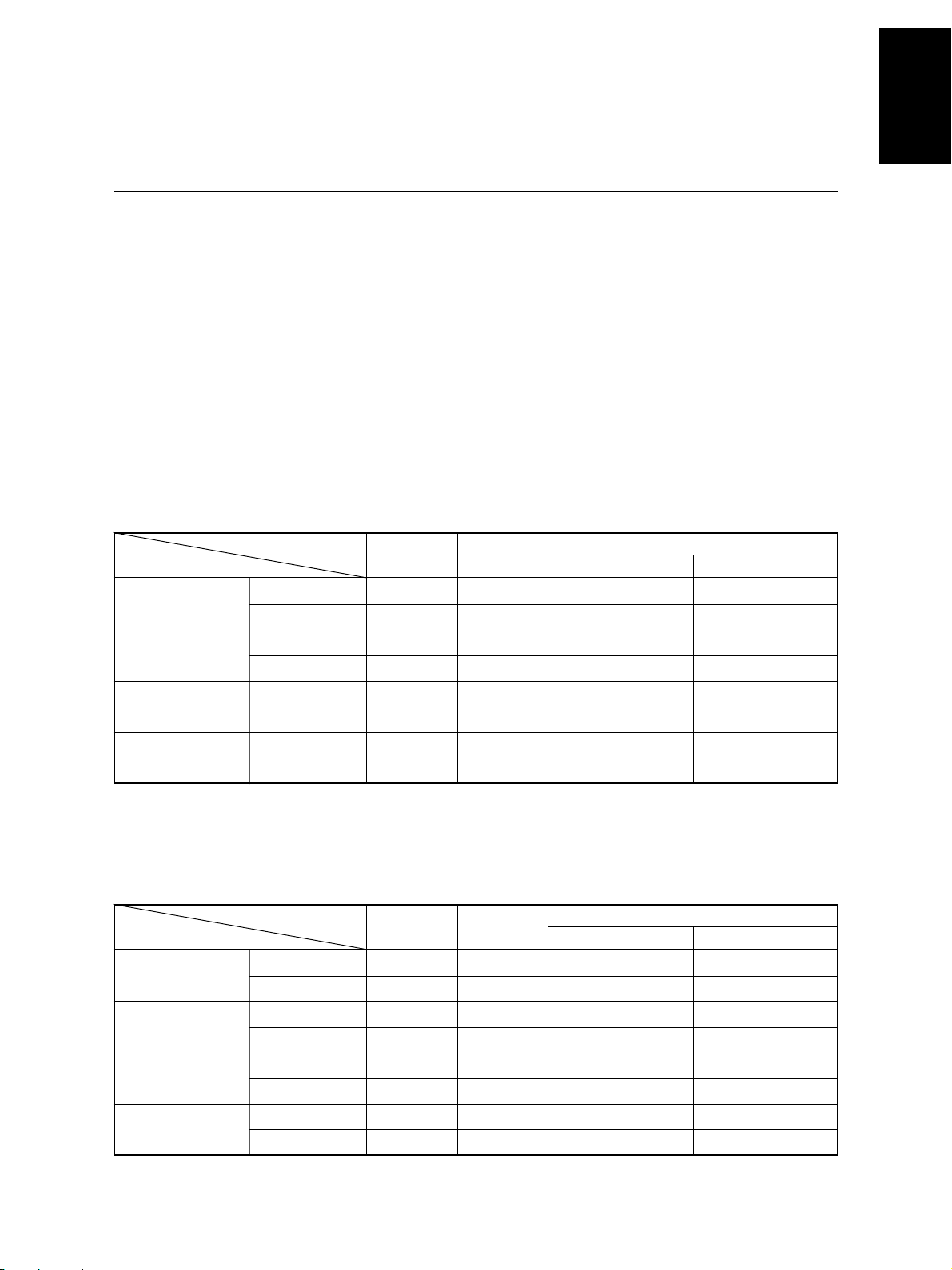
• Copy speed
e-STUDIO550 (Copies/min.)
Paper supply Tandem
Paper size Size specified Size not specified
A4, LT, B5
A4-R, B5-R,
A5-R, L T-R, ST-R
B4, LG
A3, LD
T op side discharging
Back side discharging
T op side discharging
Back side discharging
T op side discharging
Back side discharging
T op side discharging
Back side discharging
Cassette
55 55 48 33
55 55 48 30
44 — 42 33
42 — 42 30
39 — 37 33
35 — 35 30
34 — 33 33
30 — 30 30
LCF
Bypass feeding
e-STUDIO650
Paper supply Tandem
Paper size Size specified Size not specified
A4, LT, B5
A4-R, B5-R,
A5-R, L T-R, ST-R
B4, LG
A3, LD
JUNE 2002 © T OSHIBA TEC 1 - 1 e-STUDIO550/650/810 SPECIFICATIONS
T op side discharging
Back side discharging
T op side discharging
Back side discharging
T op side discharging
Back side discharging
T op side discharging
Back side discharging
Cassette
65 65 48 33
65 65 48 33
50 — 42 33
48 — 42 33
43 — 37 33
40 — 37 33
37 — 33 33
34 — 33 33
LCF
Bypass feeding
(Copies/min.)
Page 10
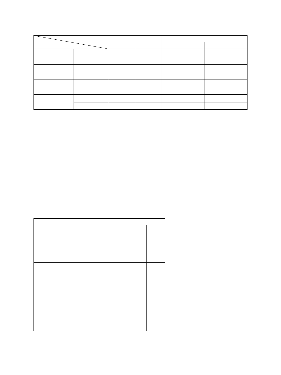
e-STUDIO810
(Copies/min.)
Paper supply
Paper size Size specified Size not specified
A4, LT, B5
A4-R, B5-R,
A5-R, L T-R, ST-R
B4, LG
A3, LD
“–” means “Not acceptable”.
*
Each copy speed described in the table of the previous page is available when doing a multiple copying
*
of the manually placed single-sided originals, and in this mode, only the top side discharging is carried
out.
When using the automatic document f eeder, each copy speed of 55 [65] {81} copies/min. is a vailable
*
only when the following conditions are met:
• Original/Mode : Single-sided original, A4/LT size, 1 sheet/APS and automatic
• Preset number of sheets: 55 [65] {81} or more.
• Reproduction ratio : 100%
T op side discharging
Back side discharging
T op side discharging
Back side discharging
T op side discharging
Back side discharging
T op side discharging
Back side discharging
Cassette
81 81 50 34
81 81 50 34
61 — 44 34
56 — 44 34
52 — 39 34
45 — 39 34
43 — 34 34
37 — 34 34
density are not selected.
Tandem
LCF
Bypass feeding
System copy speed
*
Copy mode
e-STUDIO e-STUDIO e-STUDIO
550 650 810
Single-sided originals 1 set 18"86 16"81 15"96
훹 3 sets 40"17 35"99 30"52
Single-sided copies 5 sets 61"92 53"56 45"19
Single-sided originals 1 set 21"28 20"70 20"46
훹 3 sets 42"91 39"47 36"37
Double-sided copies 5 sets 64"89 57"70 49"48
Double-sided originals 1 set 35"32 35"21 34"36
훹 3 sets 78"61 71"70 63"89
Double-sided copies 5 sets 121"96 108"01 95"06
Double-sided originals 1 set 31"77 31"49 30"88
훹 3 sets 74"75 67"97 60"58
Single-sided copies 5 sets 117"88 104"64 90"02
e-STUDIO550/650/810 SPECIFICA TIONS 1 - 2 JUNE 2002 © TOSHIBA TEC
sec.
System copy speed, including
*
scanning time, is available when 10
sheets of A4-sized original are set
on RADF and one of the copy modes
in the left table is selected.
1st cassette is selected and copying
*
is at the sort mode.
Finisher, hole-punch unit and inserter
*
are installed.
Measurement deviation is included
*
since the system copy speed was
measured by actual measurement.
Page 11
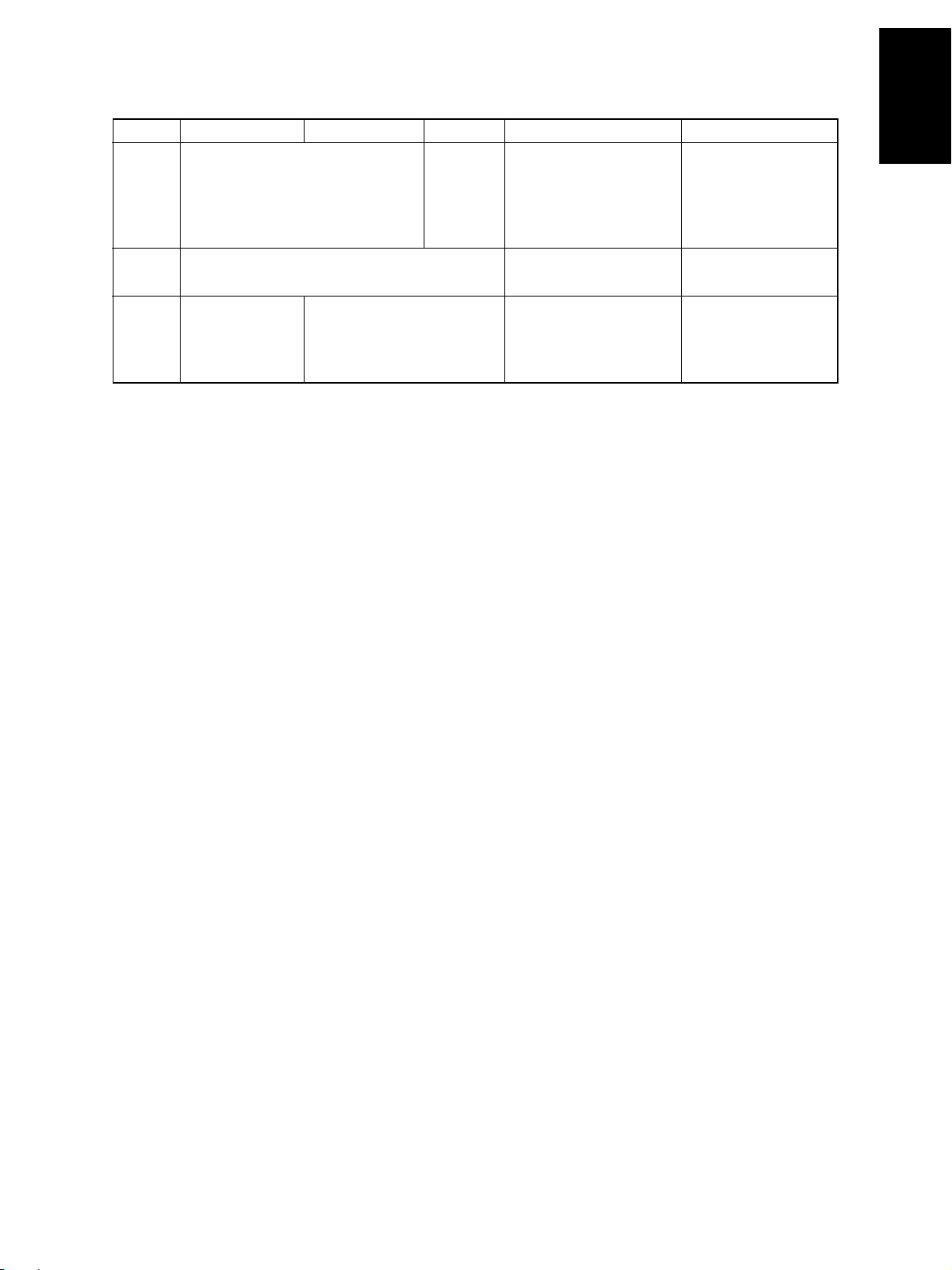
• Copy paper
Cassette Duplex copy LCF Bypass copy Remarks
Size A3~A5R, A4, LT A3~A5-R, LD~ST -R, No guarantee for 8K,
LD~ST-R, 13"LG, 8.5"x8.5", 8.5"x8.5", 8K, 16K, 16K-R 16K, 16K-R at duplex
8K, 16K, 16K-R
(Non-standard or user-
copy
specified sizes can be set.)
Weight 64~209g/m2, 17~110lb. -inde x 64~209g/m
2
17Ib~110Ib -index
Special Tab paper _
paper
(2nd casette only) OHP film (thickness: should be recommanded
T racing paper , labels, Special types of paper
80µm or thicker), tab paper by T oshiba.
• First copy time ..................3.3 seconds or less (A4/L T, LCF, 100%, original placed manually)
• Warming-up time ................ Approx.160 seconds (e-STUDIO550/650/810, T emper ature: 20°C)
Notes: 1. This is at the condition not entering the toner supply operation.
2. The auto job start is not operated.
• Multiple copying.................Up to 9999 copies; set number entered with digital keys
• Reproduction ratio..............Actual ratio: 100±0.5%
Zooming: 25~400% in increments of 1%
(25~200% when using the RADF)
• Resolution/Gradation ......... Read: 600 dpi
.........Write: Equivalent to 2400 dpi x 600 dpi
(primary scanning only : 4 division smoothing)
• Eliminated image width......Leading edge: 3.0±1.0 mm, Trailig edge: 2.0±1.0 mm, Side edges: 2.0±2.0 mm
• P aper f eeding.....................Automatic feeding: Copier cassettes–2 cassettes (Paper stac k height
55 mm, equivalent to 550 sheets; 64 to 80 g/m2 (17
to 22 lb.Bond))
LCF (Paper stac k height 137 mm: equiv alent to 2500
sheets; 64 to 80 g/m2, 17 to 22 lb.Bond)
Bypass feeding: (Paper stac k height 11 mm : equivalent to 100 sheets;
64 to 80 g/m2, 17 to 22 lb.Bond)
• Capacity of originals in the automatic document feeder
.................A3~A5-R, LD~ST-R
: 100 sheets
• Automatic duplexer............Stackless, Switchback type
• Toner supplying..................Automatic toner density detection/supply
T oner cartridge replacing method
(There is a recycle toner supplying system.)
JUNE 2002 © T OSHIBA TEC 1 - 3 e-STUDIO550/650/810 SPECIFICATIONS
Page 12
• Density control ..................Automatic density mode and manual density mode selectable in 11 steps
• Weight ............................... Approx. 200kg, 441lb
• P ow er requirements ...........AC 115V/15A, AC 220 – 240V/10A
• Power consumption ...........2.0 kW or less (115V series, 200V series)
The electric power is supplied to the finisher and external LCF (optional) through the copier .
*
• T otal counter ......................Electronic counter
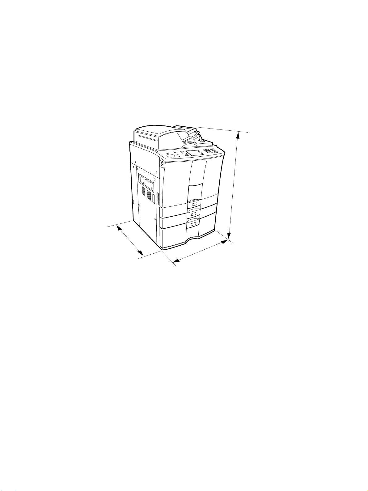
• Dimensions of the copier ... See the figure below . (W698x D778 x H1207 mm)
1207 mm
778 mm
698 mm
e-STUDIO550/650/810 SPECIFICA TIONS 1 - 4 JUNE 2002 © TOSHIBA TEC
Page 13
1. 2. Accessories
Unpacking/setup instruction 1 pc.
Operator’s Manu al 1 pc. (not available for MJD)
PM sticker 1 pc. (for MJD)
Setup report 1 set. (for NAD and MJD)
Customer satisfaction card 1 pc. (for MJD)
Operator’s Manual pocket 1 pc.
P ow er cable 1 pc. (for ASD, AUD and MJD)
Warr anty sheet 1 pc. (for NAD)
Drum 1 pc.
Drum cover 1 pc.
Original feeding tray 1 pc.
Tab paper end guide 1 pc.
* Machine version
NAD: North America
MJD: Europe
AUD: Australia
ASD: Asia
JUNE 2002 © T OSHIBA TEC 1 - 5 e-STUDIO550/650/810 SPECIFICATIONS
Page 14
1. 3. Options
Finisher MJ-1017, MJ-1018
Hole punch unit MJ-6003N/E/F/S
Inserter MJ-7001
Staple cartridge STAPLE-600/STAPLE-700 (for saddle stitcher)
External large capacity feeder MP-4003A/L
Key copy counter/Key copy counter socket MU-8/MU-10
Damp heater kit MF-6510U/E
Printer controller GL-1020
Printer board GA-1140
1. 4. Supplies
Drum OD- 6510
Developer material D-6510
T oner PS-ZT6510/PS-ZT6510/PS-ZT -6510D
T oner bag PS-TB6510/PS-TB6510E
e-STUDIO550/650/810 SPECIFICA TIONS 1 - 6 JUNE 2002 © TOSHIBA TEC
Page 15
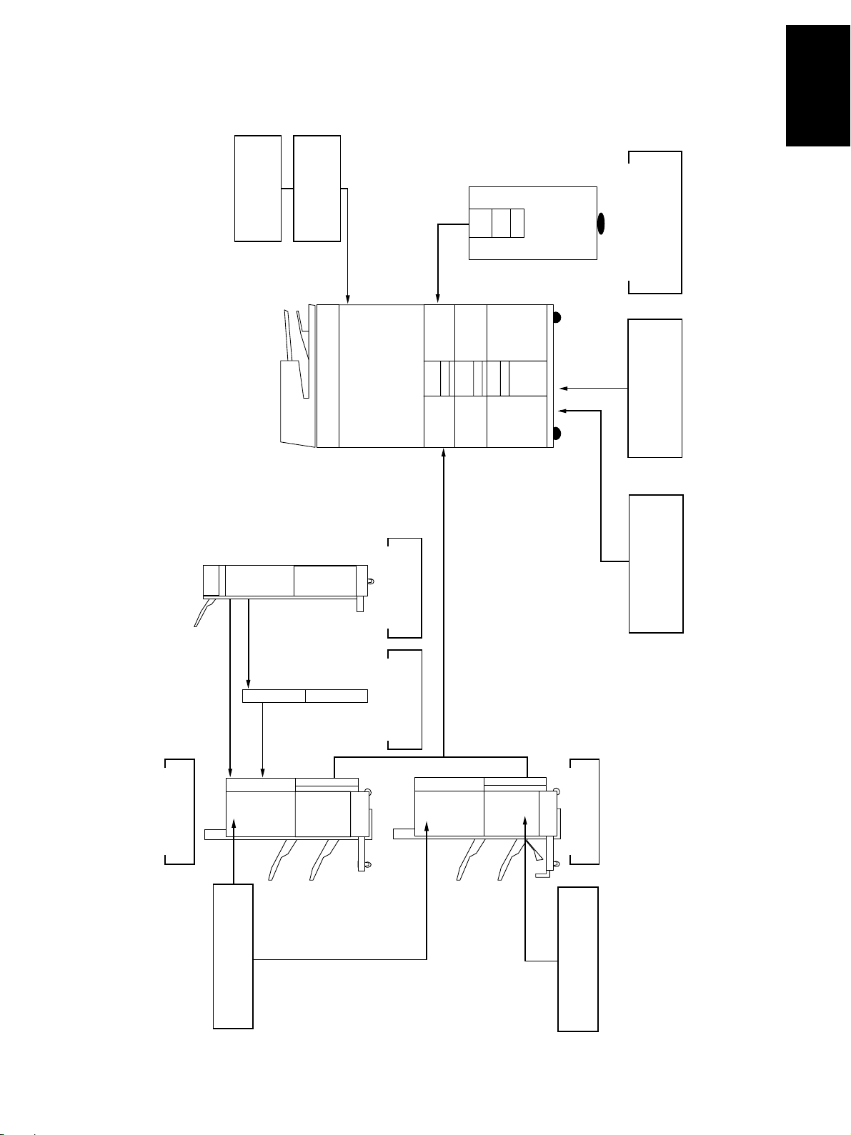
1. 5. System List
Ke y counter
Key counter socke t
MU-10
MU-8
LCF
MP-4003
Printer board
GA-1140
Finisher
MJ-1017
Staple cartridge
STAPLE-600
Inserter
MJ-7001
Hole punch unit
MJ-6003
Finisher
MJ-1018
Staple cartridge
STAPLE-700
Printer controller
GL-1020
JUNE 2002 © T OSHIBA TEC 1 - 7 e-STUDIO550/650/810 SPECIFICATIONS
Page 16
2. ERR OR CODES AND SELF-DIAGNOSIS
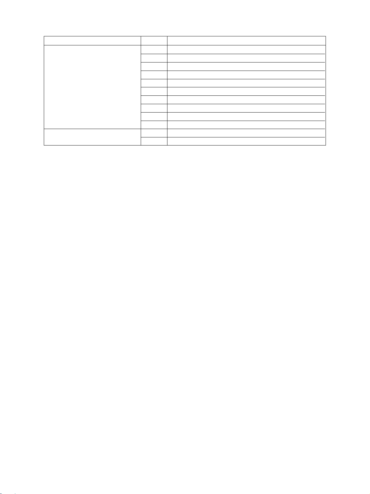
2. 1. Error Codes
Instead of the set number, one of the following error codes is displayed with pressing the [CLEAR] key and
the digital key “8” simultaneously when the “CLEAR PAPER” or “CALL SERVICE” symbol is flashing.
Group
Paper transport jam inside the E01 Leading edge of paper not reaching the fuser exit sensor
copier (1) E02 T railing edge of paper not passing the fuser e xit sensor
Paper misfeeding E11 Misfeeding during duplex printing
Paper transport jam inside the copier (2) E20 Paper fed from the 1st cassette
Error Code
E03 Paper remaining inside the copier at power ON
E09 Jam caused by an abnormal HDD
(paper not reaching the registration sensor)
E12 Bypass misfeeding
(paper not reaching the registration sensor)
E13 1st cassette misfeeding
(paper not reaching the 1st cassette feed sensor)
E14 2nd cassette misfeeding
(paper not reaching the 2nd cassette feed sensor)
E15 3rd cassette misfeeding
(paper not reaching the 3rd cassette feed sensor)
E16 4th cassette misfeeding
(paper not reaching the 4th cassette feed sensor)
E18 Tandem LCF misfeeding
(paper not reaching the tandem LCF feed sensor)
E19 External LCF misfeeding
(paper not reaching the external LCF feed sensor)
(not reaching the registration sensor)
E21 Paper fed from the 1st cassette
(not reaching the 1st cassette transport sensor)
E22 Paper fed from the 2nd cassette
(not reaching the registration sensor)
E23 Paper fed from the 2nd cassette
(not reaching the 1st cassette transport sensor)
E24 Paper fed from the 2nd cassette
(not reaching the 2nd cassette transport sensor)
E25 Paper fed from the e xternal LCF
(not reaching the registration sensor)
E30 Paper fed from the 3rd cassette
(not reaching the registration sensor)
E31 Paper fed from the 3rd cassette
(not reaching the 1st cassette transport sensor)
E32 Paper fed from the 3rd cassette
(not reaching the 2nd cassette transport sensor)
Machine Status
JUNE 2002 © T OSHIBA TEC 2 - 1 e-STUDIO550/650/810
ERROR CODES AND SELF-DIAGNOSIS
Page 17
Group
Paper transport jam inside the copier (2) E33 Paper fed from the 3rd cassette
Cover open jam E41 Front cover opened during printing
Transpor t jam (exit/reversing section E5 0 Leading edge of paper not reaching the reverse sensor 2
and others) E51 Leading edge of paper not reaching the transport sensor 1
T r ansport jam (RADF) E71 Original feeding jam
Error Code
(not reaching the 3rd cassette transport sensor)
E34 Paper fed from the 4th cassette
(not reaching the registration sensor)
E35 Paper fed from the 4th cassette
(not reaching the 1st cassette transport sensor)
E36 Paper fed from the 4th cassette
(not reaching the 2nd cassette transport sensor)
E37 Paper fed from the 4th cassette
(not reaching the 3rd cassette transport sensor)
E38 Paper fed from the 4th cassette
(not reaching the 4th cassette transport sensor)
E3C Paper fed from the tandem LCF
(not reaching the registration sensor)
E3D Paper fed from the tandem LCF
(not reaching the 1st cassette feed sensor)
E3E Paper fed from the tandem LCF
(not reaching the 2nd cassette feed sensor)
E3F Paper fed from the tandem LCF
(not reaching the tandem LCF transport sensor)
E44 Feed cover opened during printing
E45 LCF side cover opened during printing
E46 Bypass feed unit cover opened during printing
E47 Exit cover opened during printing
E52 Leading edge of paper not reaching the transport sensor 2
E54 Leading edge of paper not reaching the transport sensor 3
E55 Paper remaining on the transport path when CRUN is OFF
E57 Leading edge of paper not reaching the reverse sensor 1
E58 Trailing edge of paper not passing the reverse sensor 1 or
reverse sensor 2
E59 T railing edge of paper not passing the e xit sensor
E5A Leading edge of paper not reaching the exit sensor
E72 Original transport jam
E73 Original discharging jam
E74 Original reversing jam
E76 Small original discharging jam
E77 Scanning section transport jam
E7B RADF opened at the original transporting
E7C RADF opened at the large original discharging
E7D RADF opened at the small original reversing
E7E RADF opened at the small original discharging
E7F RADF opened at the original scanning section
Machine Status
e-STUDIO550/650/810
ERROR CODES AND SELF-DIAGNOSIS
2 - 2 JUNE 2002 © T OSHIBA TEC
Page 18
Group
T ransport jam (RADF) E8 0 Jam access cover opened at the original feeding
Paper jam in finisher E9F Punching jam
Paper transport jam inside the EB5 Paper left on the transport path
copier (3) EB6 Paper left on the transport path
Error Code
E81 Jam access cover opened at the original transporting
E82 Jam access cover opened at the large original dischaging
E83 Jam access cover opened at the small original reversing
E84 Jam access cover opened at the small original discharging
E85 Jam access cover opened at the original scanning section
EA1 Finisher paper transport delay jam
EA2 Finisher paper transport stop jam
EA3 Paper remaining inside the finisher at power ON
EA4 Finisher front door opened during printing
EA5 Finisher stapling jam
EA6 Finisher early arrival jam
EA7 Stack transport jam before stapling
EA8 Saddle stitcher stapling jam
EA9 Saddle stitcher door opened during printing
EAA Paper remaining at the saddle stitcher at power ON
EAB Saddle stitcher paper transport stop jam
EAC Saddle stitcher paper transport delay jam
EAD Print end command time-out jam
EAE Receiving time time-out jam
EB3 Ready time time-out jam
EC0 Inserter feeding delay jam
EC1 Inserter feeding stop jam
EC2 Inserter reverse path delay jam 1
EC3 Inserter reverse path stop jam 1
EC4 Inserter reverse path delay jam 2
EC5 Inserter reverse path stop jam 2
EC6 Inserter transport delay jam 1
EC7 Inserter transport stop jam 1
EC8 Inserter transport delay jam 2
EC9 Inserter transport stop jam 2
ECA Paper remaining in the inserter when power is ON
ECB Wrong size of inserter
ECC Inserter feeding Jam
Machine Status
JUNE 2002 © T OSHIBA TEC 2 - 3 e-STUDIO550/650/810
ERROR CODES AND SELF-DIAGNOSIS
Page 19
Group
Paper feeding system related service call
Scanning system related service call C26 Peak detection error
Processing system related service call C36 Abnormal main charger wire cleaner drive motor
Fuser unit related service call C41 Abnormal thermistor or heater at the power ON
Error Code
C04 Abnormal feed motor
C1 3 Abnormal 1st cassette tray (Paper can be fed from cassettes
other than the 1st cassette.)
C14 Abnormal 2nd cassette tray (Paper can be fed from cassettes
other than the 2nd cassette.)
C15 Abnormal 3rd cassette tray (Paper can be fed from cassettes
other than the 3rd cassette.)
C16 Abnormal 4th cassette tray (Paper can be fed from cassettes
other than the 4th cassette.)
C1 8 Abnormal tandem LCF tray-up motor
(Paper can be fed from cassettes other than the tandem LCF
cassette.)
C1A Abnormal tandem LCF end fence motor
(Paper can be fed from cassettes other than the tandem LCF
cassette.)
C1C Abnormal external LCF tray-up motor
(Paper can be f ed from cassettes other than the external LCF)
C27 Carriage home position sensor not going OFF within a fixed time
C28 Carriage home position sensor not going ON within a fixed time
C37 Abnormal transfer belt cam motor
CD1 Abnormal drum cleaning brush motor
CD2 Abnormal used toner transport motor
CD3 Abnormal recycle toner transport motor
CD4 Full toner bag
C43 Abnormal thermistor after abnormality judgment
C44 Abnormal fuser after abnormality judgment
C45 Abnormal side thermistor after the copier has become ready
C46 Abnormal pressure roller thermistor during a ready state
C47 Abnormal IH power voltage / IH initialization error
C48 IGBT high temperature
C49 Abnormal IH circuit or coil
C4A Cleaning web finished
CD5 Web motor signal path error
Machine Status
e-STUDIO550/650/810
ERROR CODES AND SELF-DIAGNOSIS
2 - 4 JUNE 2002 © T OSHIBA TEC
Page 20
Group
Communication related service call C55 RADF I/F error
RADF related service call C73 EEPROM initialization error
Laser optical unit related service call CA1 Abnormal polygonal motor
Finisher related service call CB1 Abnormal feed motor
Error Code
C56 Communication error between main CPU and PFC
C57 Communication error between main CPU and IPC board
C58 Communication error between IPC board and finisher
C59 Communication error between main CPU and laser CPU
F07 Communication error between SYS board and LGC board
F11 Communication error between SYS board and SLG board
C82 Read sensor adjustment error
C83 Original length sensor adjustment error
C84 Small original reverse sensor adjustment error
C85 Abnormal tray lift motor
C86 Large original exit sensor adjustment error
CA2 H-Sync detection error
CA3 Secondary scanning coarse adjustment error
CA5 Laser power adjustment error
CA6 Laser calibration error
CA9 Image data transmission error from SYS board
CAA Secondary scanning fine adjustment error
CAB Secondary scanning inter-page compensation error
CAC Primary scanning dot adjustment error
CD 0 Laser initializing time out
CE0 Abnormal comparator
CE1 Beam sensor detection error
CE2 Sensor busy error
CE3 Primary scanning adjustment error
CE4 Abnormal window comparator
CB2 Abnormal delivery motor
CB3 Abnormal tray lift motor
CB4 Abnormal alignment motor
CB5 Abnormal staple motor
CB6 Abnormal stapler shift motor
CB7 Abnormal height sensor
CB8 Abnormal backup RAM data
CB9 Abnormal saddle stitcher paper pushing plate motor
CBA Abnormal saddle stitcher stitch motor (front)
CBB Abnormal saddle stitcher stitch motor (rear)
CBC Abnormal saddle stitcher alignment motor
CBD Abnormal saddle stitcher guide motor
CBE Abnormal saddle stitcher paper folding motor
CBF Abnormal saddle stitcher paper positioning plate motor
Machine Status
JUNE 2002 © T OSHIBA TEC 2 - 5 e-STUDIO550/650/810
ERROR CODES AND SELF-DIAGNOSIS
Page 21
Group
Finisher related service call CC0 Abnormal saddle stitcher sensor connector connection
Service call for others C94 Abnormal main CPU
Error Code
CC1 Abnormal saddle stitcher microswitch
CC2 Abnormal communication between finisher and saddle stitcher
CC4 Abnormal swing motor
CC5 Abnormal horizontal registration motor
CC6 Abnormal punch motor
CC7 Abnormal punch unit backup RAM data
CCC Communication error between inserter and finisher
CCD Abnormal inserter EEPROM
CCE Abnormal inserter fan
F10 HDD formatting error
Machine Status
e-STUDIO550/650/810
ERROR CODES AND SELF-DIAGNOSIS
2 - 6 JUNE 2002 © T OSHIBA TEC
Page 22
<<Error history (08-253)>>
(Example of display)
Copy mode
A Paper source
0: Not selected 1: Bypass feeding 2:Tandem LCF 3: 1st cassette 4: 2nd cassette 5: 3rd cassette
6: 4th cassette 7: Duplex printing 8: External LCF 9: Inserter
B Paper size code
0: Not selected 1: A5-R 2: ST-R 3: LT 4: A4 5: B5-R 6: LT-R 7: A4-R 8: OTHER/UNIV 9: B5
A: FOL/COM B: LG C: B4 D: LD E: A3 F: 13'LG G: 8.5*8.5 H: 8K I:16K J:16K-R
C Sort mode/Staple mode
0: Non-sort/Non-staple 1: Group 2: Sort 7: Staple sort (standard) 8: Staple sort (2 places)
9: Staple sort (rear side) A: Saddle stitch
D ADF mode
0: Not used 1: AUTO FEED (SADF) 2: STACK FEED
E APS/AMS mode
0: Not selected 1: APS 2: AMS
F Duplex mode
0: Not selected 1: Book 2: Two-sided/Single-sided 4: T wo-sided/Duple xed
8: Single-sided/Duplexed
G Not used
0: Not used
H Image shift
0: Not used 1: Book 2: Left 3: Right
I Editing
0: Not used 1: Masking 2: Trimming 3: Mirror image 4: Negative/Positive
J Edge erasing/Dual-page
0: Not used 1: Edge erase 2: Dual-page 3: Edge erase & Dual-page
K Not used
0: Not used
L Function
0: Not used 1: Copying 2: Not used 3: Not used 4: LAN printer 5: DSS
EA1
Error code
3 digits
0 2 0 6 2 6 1 7 5 7 3 2
YYMMDDHHMMSS
with its last 2 digits)
6 4
MMM
3 digits
3 digits12 digits (Year indicated
6 4
NNN
2 3 6 2 1 0 0 0 0 0 0 0
ABCDEFGHIJKL
12 digits
Reproduction ratio
MMM Primary scanning reproduction ratio
Shown in hexadecimal
NN N Secondary scanning reproduction ratio
Shown in hexadecimal
The latest 20 errors data can be displayed in the setting mode (08-253).
JUNE 2002 © T OSHIBA TEC 2 - 7 e-STUDIO550/650/810
ERROR CODES AND SELF-DIAGNOSIS
Page 23
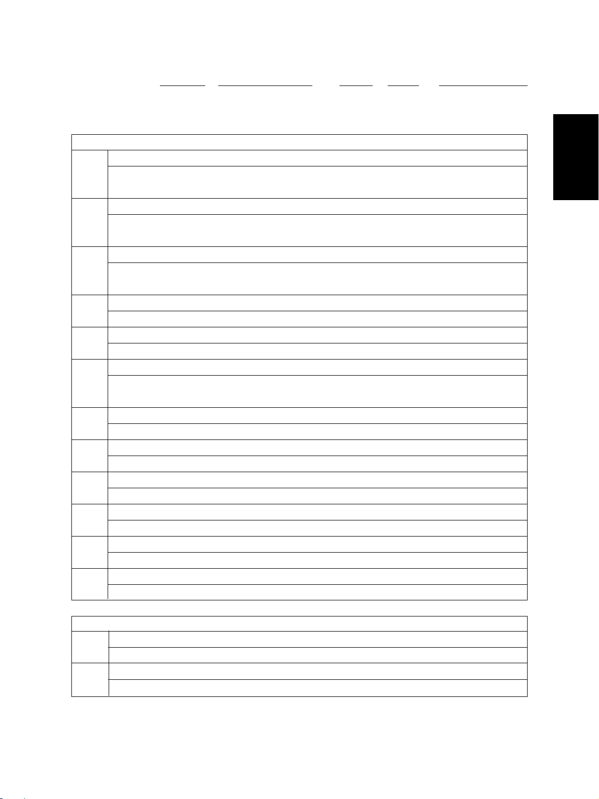
2. 2. Self-diagnosis Modes
Mode
Control panel [0]+[1]+ All LEDs on the control panel are lit, and all [CLEAR] or
check mode [POWER] the LCD pixels flash.
T est mode [0]+[3]+ Checks the status of input/output signals. [POWER] 100% C
Test print mode [0]+[4]+ Outputs the test patterns. [POWER] 100% P A4
Adjustment mode [0]+[5]+ Adjusts various items. [POWER] 100% A A4
Setting mode [0]+[8]+ Sets various items. [POWER] 100% D
List printing mode
PM support mode
Firmware [3]+[9]+ Performs updating of the firmware. [POWER]
update mode [POWER] OFF/ON
Keys to
press exit
[POWER] OFF/ON TEST MODE
[POWER] OFF/ON TEST PRINT
[POWER] OFF/ON TEST MODE
[POWER] OFF/ON TEST MODE
[9]+[START]
+[POWER]
[6]+[START]
+[ POWER ]
Prints out the data lists of the codes 05 and [POWER] 100% L A4
08 and PM support mode. OFF/ON LIST PRINT
Perf orms auto-toner adjustment and clears [POWER] 100% K
each counter. OFF/ON TEST MODE
Contents
Keys to
[POWER] OFF/ON
Display
Note: To enter the desired mode, turn ON the power while two digital keys designated to each mode (e.g. [0] and
[5]) are pressed simultaneously.
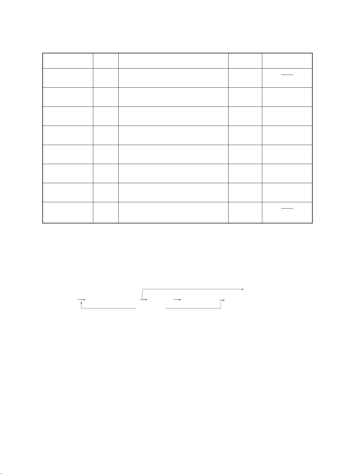
<Operation procedure>
• Control panel check mode (01):
[CLEAR] or [POWER]OFF/ON
(Exit)
[0] [1]
[POWER]
Notes: 1. A mode can be canceled only by pressing the [CLEAR] key during the key check and by the [CLEAR]
key or [POWER] OFF/ON during the LED and LCD are lit.
2. Key Check Keys with LED (Press to turn OFF the LED.)
(LED/LCD lit)
Keys without LED (Press to display the message on the control panel.)
[START]
[START]
(Key check) [CLEAR] (Exit)
e-STUDIO550/650/810
ERROR CODES AND SELF-DIAGNOSIS
2 - 8 JUNE 2002 © T OSHIBA TEC
Page 24
• Test mode (03): Refer to “2.2.1. Input check (test mode 03)” and “2.2.2. Outpout check (test mode 03)”.
• Test print mode (04): Refer to “2.2.3. Test print mode (04)”.
• Adjustment mode (05): Refer to “2.2.4. Adjustment mode (05)”.
• Setting mode (08): Refer to “2.2.5. Setting mode (08)”.
• List printing mode (9S):
[9] [START]
[POWER]
(code)
101:Adjustment mode(05)
(List starts to be printed)
[START]
102:Setting mode(08)
103: PM support mode
• PM support mode (6S):
[6] [START]
[POWER]
(code) [POWER] OFF/ON
1: Auto-toner adjustment
2: PM management screen
[START]
(Operation started)
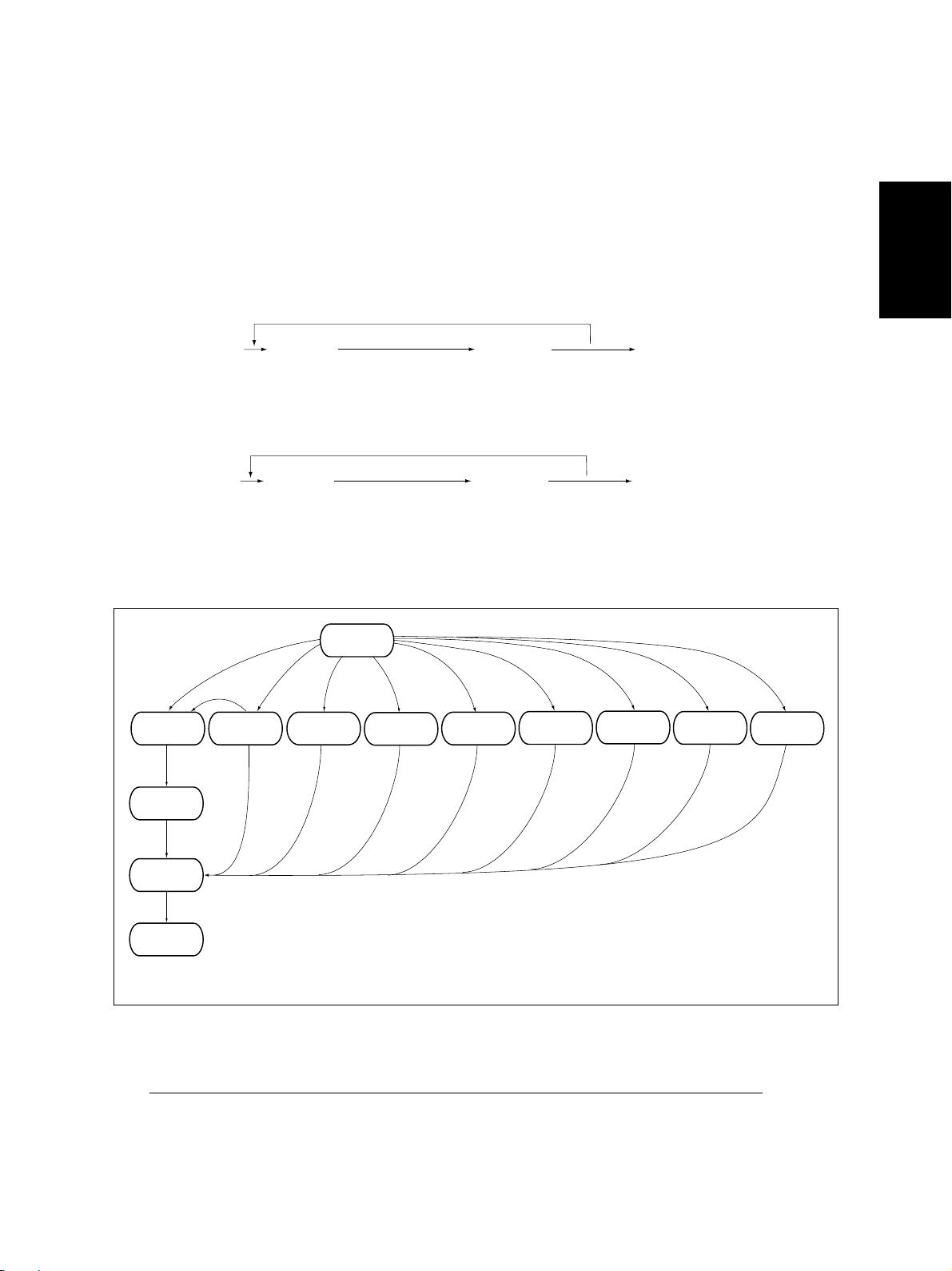
• Firmware update mode (39): Refer to “6. FIRMWARE UPDATING”.
[POWER]
ON
T est print
mode
Adjustment
mode
[0][8][0][4]
Setting
mode
Warming up
Standby
Normal
[CLEAR]
Control panel
check mode
*1
[0][1] [0][3] [0][5]
Test mode
[POWER] OFF/ON
(Exit)
(Exit)
[9][START]
List print
mode
PM support
[6][START]
mode
[3][9]
Firmware
update mode
[POWER]
OFF
*2
To user
State transition diagram of self-diagnosis modes
*1 In the “Control panel check mode”, copying is disabled. Enter the standby state by pressing the
[CLEAR] key to start copying.
*2 Turn OFF the power after using the self-diagnosis mode, and leave the copier to the user.
JUNE 2002 © T OSHIBA TEC 2 - 9 e-STUDIO550/650/810
ERROR CODES AND SELF-DIAGNOSIS
Page 25
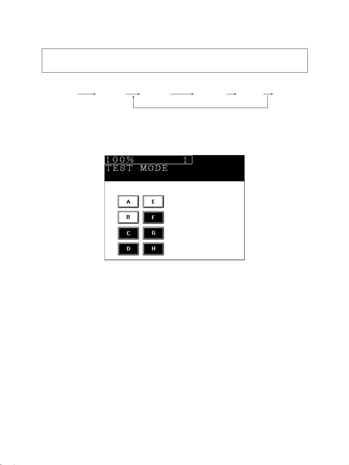
2. 2. 1. Input check (test mode 03)
The state of each input signal can be checked by pressing the [ENERGY SAVER] key and the
digital keys in the test mode (03).
<Operation procedure>
[0] [3]
[POWER]
Note: Initialization is performed before the copier enters the test mode.
[START] ([ENERGY
SAVER])
[Digital key] (LCD ON)
[POWER]
OFF/ON
(Exit)
[Example of display during input check]
Items to be checked and the state of the copier with the icons [A] to [H] displayed in black are listed on the
following pages.
e-STUDIO550/650/810
ERROR CODES AND SELF-DIAGNOSIS
2 - 10 JUNE 2002 © TOSHIBA TEC
Page 26

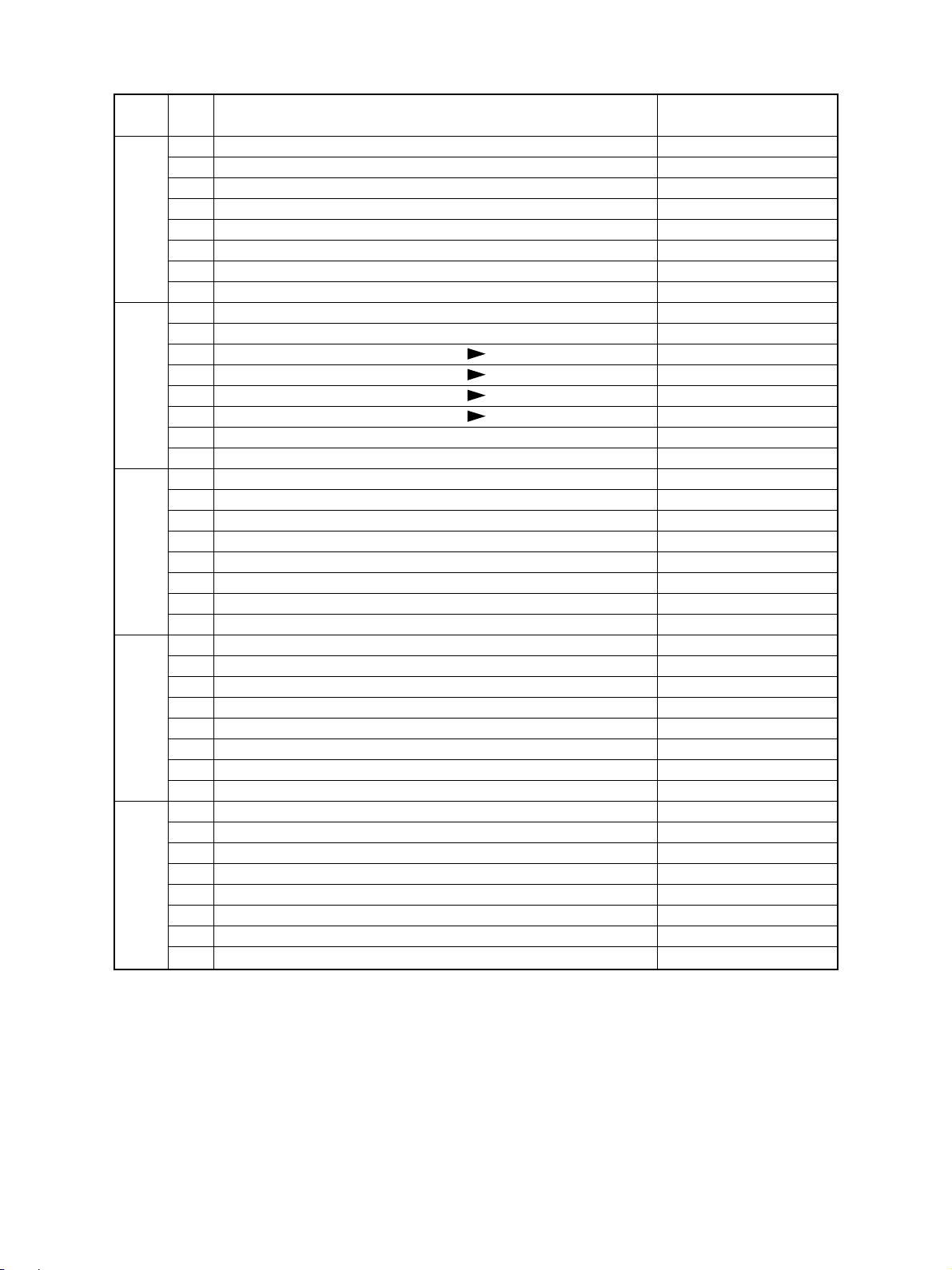
[ENERGY SAVER] key: OFF ( [ENERGY SAVER] LED: OFF)
Digital
Icon Items to check
key with black icon
A—
B External LCF feed sensor No paper —
C External LCF tray-up sensor Top position
[1]
[2]
[3]
[4]
[5]
D External LCF tray bottom sensor Bottom position
E External LCF tray sensor Stack opened
F External LCF empty sensor No paper
G External LCF set sensor Unit opened
H External LCF connection Not connected
A 1st cassette feed sensor No paper
B 1st cassette transport sensor No paper
C 1st cassette tray top sensor Top position
D 1st cassette tray bottom sensor Bottom position
E 1st cassette detection switch Cassette installed
F 1st cassette paper empty sensor No paper
G—
H—
A 2nd cassette feed sensor No paper
B 2nd cassette transport sensor No paper
C 2nd cassette tray top sensor Top position
D 2nd cassette tray bottom sensor Bottom position
E 2nd cassette detection switch Cassette installed
F 2nd cassette paper empty sensor No paper
G—
H—
A 3rd cassette feed sensor / Tandem LCF feed sensor No paper
B 3rd cassette transport sensor / Tandem LCF transport sensor No paper
C 3rd cassette tra y top sensor / Tandem LCF tray top sensor T op position
D 3rd cassette tray bottom sensor Bottom position
E 3rd cassette detection switch / Tandem LCF cassette detection switch Cassette installed
F
3rd cassette paper empty sensor/ Tandem LCF f eeding side paper empty sensor
G Feed cover open/close switch Cover opened
H—
A 4th cassette feed sensor No paper
B 4th cassette transport sensor No paper
C 4th cassette tray top sensor Top position
D 4th cassette tray bottom sensor Bottom position
E 4th cassette detection switch Cassette installed
F 4th cassette paper empty sensor No paper
G—
H—
Copier state
No paper
JUNE 2002 © T OSHIBA TEC 2 - 11 e-STUDIO550/650/810
ERROR CODES AND SELF-DIAGNOSIS
Page 27
Digital
Icon Items to check
key with black icon
A—
B Reverse sensor 2 No paper
C Reverse sensor 1 No paper
[6]
[7]
[8]
[9]
[0]
D—
E Exit/Reversing section connection Not connected
F Fuser unit exit sensor No paper
G Exit sensor Paper present
H Exit cover open/close switch Cover opened
A Tandem LCF end fence home position sensor Home postion
B Tandem LCF end fence stop position sensor Stop position
C Bypass paper size detection sensor 3 ( Table1)
D Bypass paper size detection sensor 2 (
E Bypass paper size detection sensor 1 ( Table1)
F Bypass paper size detection sensor 0 ( Table1)
G Bypass unit cover open/close switch Door closed
H Bypass sensor No paper
A Tandem LCF tray bottom sensor Bottom position
B Tandem LCF connection switch Connected
C Tandem LCF standby side mis-stacking sensor Paper loaded improperly
D—
E—
F—
G—
H Tandem LCF standby side empty sensor No paper
A Transport sensor 1 Paper present
B Transport sensor 2 Paper present
C Transport sensor 3 Paper present
D—
E—
F—
G—
H—
A—
B—
C—
D Finisher connection (IPC board connection) Not connected
E Fuser unit switch Fuser unit installed
F—
G—
H Developer unit switch Developer unit installed
Table1)
Copier state
e-STUDIO550/650/810
ERROR CODES AND SELF-DIAGNOSIS
2 - 12 JUNE 2002 © TOSHIBA TEC
Page 28
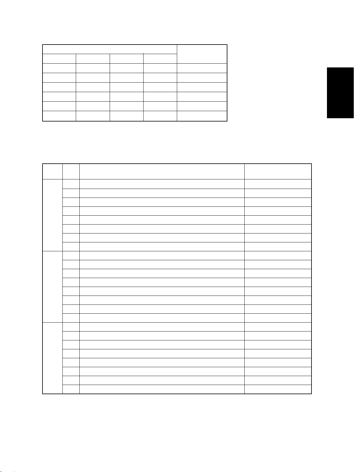
Table 1. Relation between the state of the bypass paper size detection sensor and paper size (width).
Bypass paper width sensor
3210
0 1 1 1 A3/LD
1 0 1 1 A4-R/LT-R
1 1 0 1 A5-R/ST-R
1 1 1 0 Post card
0 0 1 1 B4/LG
1001B5-R
Paper width size
[ENERGY SA VER] k e y: ON ([ENERGY SAVER] LED: ON)
Digital
Icon Items to check
key with black icon
A Front door s witch Door opened
B—
C Exit sensor Paper present
[1]
[2]
[3]
D—
E T oner full detection sensor Toner bag full
F—
G Fuser unit exit sensor No paper
H—
A—
B—
C Total counter connection Not connected
D Auto-toner sensor connection Not connected
E—
F Cleaner unit connection Not connected
G Wire cleaner stop position switch Other than stop position
H Exit jam access door open/close switch Door opened
A—
B—
C—
D—
E—
F Key cop y counter connection Not connected
G T oner cartridge switch No cartridge
H—
Copier state
JUNE 2002 © T OSHIBA TEC 2 - 13 e-STUDIO550/650/810
ERROR CODES AND SELF-DIAGNOSIS
Page 29
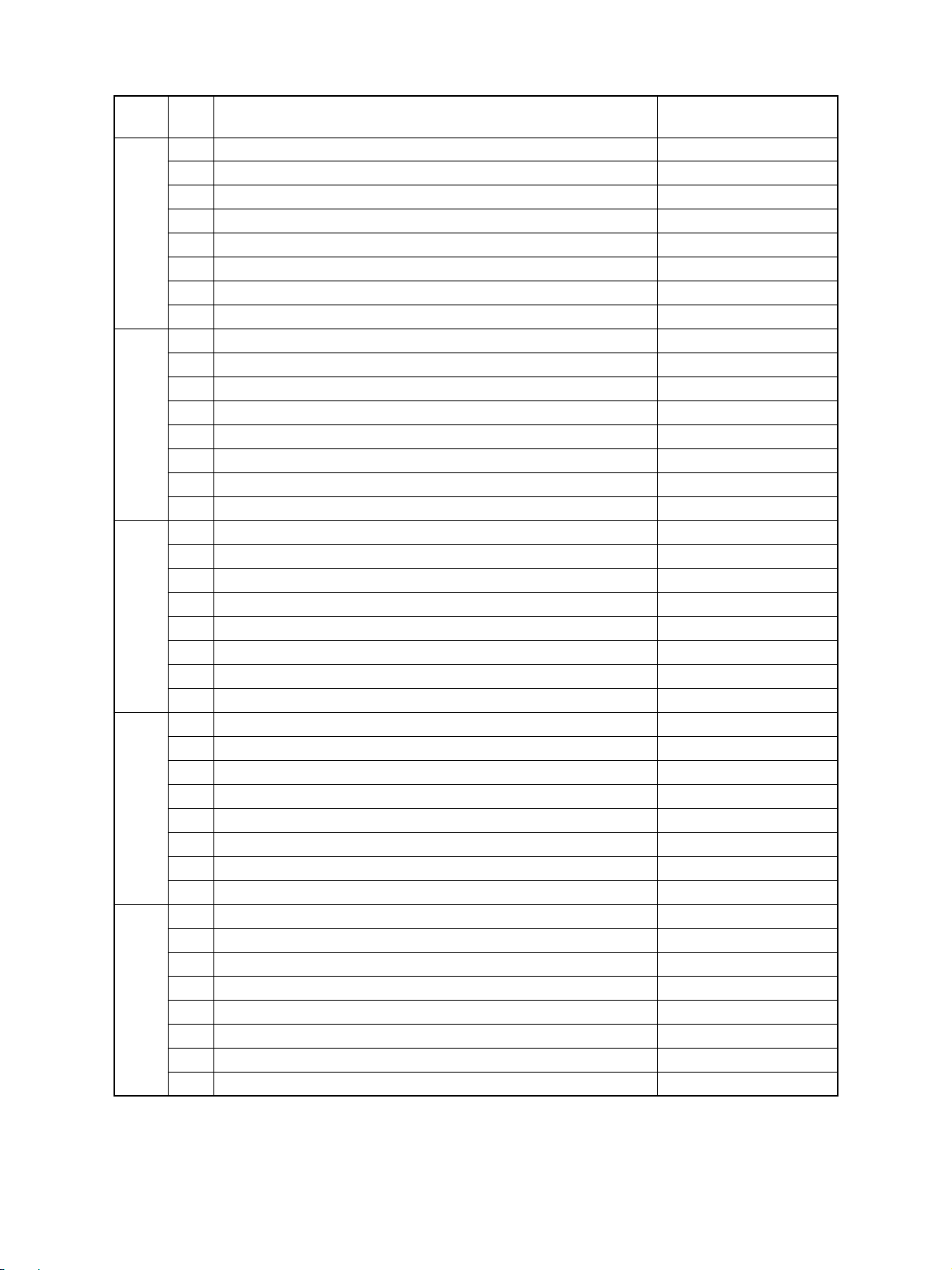
Digital
Icon Items to check
key with black icon
A—
B—
C—
[4]
[5]
[6]
[7]
[8]
D—
E Registration sensor Paper present
F—
G T ransfer belt release s witch Other than release position
H Transfer belt contact switch Other than contact position
A—
B—
C—
D—
E—
F RADF connection RADF connected
G RADF open/close sensor RADF opened
H Carriage home position sensor Home position
A—
B—
C—
D Automatic original detection sensor (APS-5) (for A 4 /LT s e ries) No original
E Automatic original detection sensor (APS-4) (f o r A 4 /LT s er ies) No original
F Automatic original detection sensor (APS-3) (for A 4/LT s e r ies) No original
G Automatic original detection sensor (APS-2) (f o r A 4 /LT s e r ies) No original
H Automatic original detection sensor (APS-1) (for A4 series) No original
A RADF tray sensor Original present
B RADF empty sensor Original present
C RADF jam access cover open/close switch Cover opened
D RADF open/close switch RADF opened
E RADF large original exit sensor Original present
F RADF intermediate sensor Original present
G RADF read sensor Original present
H RADF registration sensor Original present
A RADF lifting tray lower limit sensor Lower limit position
B RADF lifting tray upper limit sensor Upper limit position
C RADF small original exit sensor Original present
D RADF small original reverse sensor Original present
E RADF original length sensor Original present
F RADF original width sensor-1 Original present
G RADF original width sensor-2 Original present
H RADF original width sensor-3 Original present
Copier state
e-STUDIO550/650/810
ERROR CODES AND SELF-DIAGNOSIS
2 - 14 JUNE 2002 © TOSHIBA TEC
Page 30
Digital
Icon Items to check
key with black icon
A—
B—
C—
[9]
[0]
D—
E—
F—
G RADF APS operation sensor APS sensors operated
H RADF 24V power supply Power OFF
A—
B—
C—
D—
E—
F—
G—
H—
Copier state
JUNE 2002 © T OSHIBA TEC 2 - 15 e-STUDIO550/650/810
ERROR CODES AND SELF-DIAGNOSIS
Page 31

2. 2. 2. Output check (test mode 03)
State of the output signals can be checked by entering the codes in the following table in the test
mode 03.
Procedure 1
[0] [3]
[POWER]
Procedure 2
[0] [3]
[POWER]
Procedure 3
[0] [3]
[POWER]
Procedure 4
[0] [3]
[POWER]
(Code) [START]
(Code) [START]
(Code) [START] [START]
(Code)
[START]
Operation
started
Operation
(One direction)
Operation
started
[POWER] OFF
Code to stop
operation
[CLEAR]
Operation
stopped
[START]
Test mode
standby
Operation
stopped
[CLEAR]
[POWER]
OFF/ON
(Exit)
[POWER]
OFF/ON
(Exit)
Test mode
standby
[POWER]
OFF/ON
(Exit)
Code Function Code Function Procedure
101 Drum motor ON 151 Code 101 operation OFF 1
102 New toner supply motor ON 152 Code 102 operation OFF 1
103 Polygonal motor (600dpi) ON 153 Code 103 operation OFF 1
108 Registration motor ON 158 Code 108 operation OFF 1
110 Reversed paper transport driving clutch ON 16 0 Code 110 operation OFF 1
111 Drum separation finger solenoid ON 161 Code 111 operation OFF 1
11 2 Developer unit motor ON 16 2 Code 112 operation OFF 1
113 Fuser motor ON 163 Code 113 operation OFF 1
11 4 Transfer belt motor ON 164 Code 114 operation OFF 1
11 5 Cleaning brush drive motor ON 1 6 5 Code 115 operation OFF 1
11 6 Used toner transport motor ON 166 Code 116 operation OFF 1
11 8 Laser ON 16 8 Code 118 operation OFF 1
119 Fuser moter (low speed) ON 169 Code 119 operation OFF 1
120 Exit motor (normal) ON 170 Code 120 operation OFF 1
e-STUDIO550/650/810
ERROR CODES AND SELF-DIAGNOSIS
2 - 16 JUNE 2002 © TOSHIBA TEC
Page 32

Code Function Procedure
121 Exit motor (increased speed) ON 171 Code 121 operation OFF 1
122 External LCF feed motor ON 172 Code 122 operation OFF 1
123 Toner recycle hopper motor ON 173 Code 122 operation OFF 1
124 Web motor ON 174 Code 122 operation OFF 1
125 Feed motor ON 175 Code 122 operation OFF 1
126 Reverse motor (normal/forward rotation) ON 176 Code 122 operation OFF 1
127
Reverse motor (increased speed/forward rotation) ON
128 Reverse motor (normal/reverse rotation) ON 1 78 Code 122 operation OFF 1
129
Reverse motor (increased speed/reverse rotation) ON
131 Recycle toner transport motor ON 181 Code 122 operation OFF 1
201 1st cassette feed clutch ON/OFF 3
202 2nd cassette feed clutch ON/OFF 3
203 Intermediate transport clutch ON/OFF 3
204 Bypass feed clutch ON/OFF 3
206 Tandem LCF pickup solenoid ON/OFF 3
207 T andem LCF end f ence reciprocating movement 2
208 T andem LCF end f ence motor ON/OFF 3
209 Tandem LCF feed clutch ON/OFF 3
210 Tandem LCF transport clutch ON/OFF 3
211 RADF feed motor (forward rotation) ON/OFF 3
212 RADF feed motor (reverse rotation) ON/OFF 3
213 RADF read motor (forward rotation) ON/OFF 3
218 Key cop y counter count-up 2
219 Exit fan ON/OFF 3
220 Reversed paper transport clutch 1 ON/OFF 3
221 Reversed paper ransport clutch 2 ON/OFF 3
225 4th cassette transport clutch ON/OFF 3
226 3rd cassette feed clutch ON/OFF 3
228 4th cassette feed clutch ON/OFF 3
229 1st cassette transport clutch ON/OFF 3
230 2nd cassette transport clutch ON/OFF 3
231 3rd cassette transport clutch ON/OFF 3
234 Bypass pickup solenoid ON/OFF 3
235 Discharge lamp ON/OFF 3
238 System fan ON/OFF 3
240 Developer unit fan ON/OFF 3
24 3 Main charger wire cleaner motor ON 2
24 4 Transfer belt cam motor UP/DOWN 3
24 5 Transfer belt supply roller bias TR1 ON/OFF 3
24 6 Transfer belt supply roller bias TR2 ON/OFF 3
24 7 Transfer belt supply roller bias TR3 ON/OFF 3
177 Code 122 operation OFF 1
179 Code 122 operation OFF 1
JUNE 2002 © T OSHIBA TEC 2 - 17 e-STUDIO550/650/810
ERROR CODES AND SELF-DIAGNOSIS
Page 33

Code Function Procedure
248 Developer bias +DC ON/OFF (Operation is possible without the developer unit.) 3
249 Developer bias -DC1 ON/OFF (Operation is possible without the developer unit.) 3
250 Developer bias -DC2 ON/OFF (Operation is possible without the developer unit.) 3
251 Developer bias -DC3 ON/OFF (Operation is possible without the developer unit.) 3
252 Main charger ON/OFF (Operation is possible without the developer unit.) 3
254 Duct in fan ON/OFF 3
255 Transfer belt cleaning brush bias ON/OFF (Operation is possible without the dev eloper unit.) 3
257 Duct out fan (high speed) ON/OFF 3
258 Duct out fan (low speed) ON/OFF 3
259 Heater fan (high speed) ON/OFF 3
260 Heater fan (low speed) ON/OFF 3
261
Scanner motor ON (automatically stopping at the limit position, speed changeable by the ZOOM keys)
264 SLG fan ON/OFF 3
267 Exposure lamp ON/OFF 3
270 Tandem LCF tray motor ON (tray lifted) 2
271 External LCF tray motor ON (tray lifted) 2
272 External LCF feed clutch ON/OFF 3
273 External LCF transport clutch ON/OFF 3
274 Gate solenoid ON/OFF 3
276 Cassette tray-up motor 1 ON (1st cassette tray lifted) 2
278 Cassette tray-up motor 1 ON (2nd cassettetray lifted) 2
27 9 Cassette tray-up motor 2 ON (3rd cassettetray lifted) 2
28 0 Cassette tray-up motor 2 ON (4th cassettetray lifted) 2
28 3 RADF large original exit roller (forward rotation) ON/OFF 3
28 4 RADF large original exit roller (reverse rotation) ON/OFF 3
28 5 RADF small original exit roller (forward rotation) ON/OFF 3
28 6 RADF small original exit roller (reverse rotation) ON/OFF 3
287 RADF large original exit solenoid ON/OFF 3
288 RADF small original exit solenoid ON/OFF 3
289 RADF disengagement solenoid ON/OFF 3
290 RADF tray lift motor ON (tray lifted) 2
29 2 Laser unit fan (high speed) ON/OFF 3
293 Laser unit fan (low speed) ON/OFF 3
29 5 Power OFF mode 4
450 IH fan (high speed) ON/OFF 3
451 IH fan (low speed) ON/OFF 3
45 2 Reverse section fan 1 (high speed) ON/OFF 3
45 3 Reverse section fan 1 and 2 (low speed) ON/OFF 3
454 Reverse section fan 2 (high speed) ON/OFF 3
2
e-STUDIO550/650/810
ERROR CODES AND SELF-DIAGNOSIS
2 - 18 JUNE 2002 © TOSHIBA TEC
Page 34

2. 2. 3. Test print mode (test 04)
The built-in test pattern can be printed out by entering the following codes in the test print mode (04).
<Operation procedure>
[0] [4]
[POWER]
Notes: 1. An error code is displayed on the control panel if an error occurs in the process, but no recovery
Code Types of test pattern Remarks
11 1 Primary scanning direction, 33 gradation steps, error diffusion
11 3 Secondary scanning direction, 33 gradation steps, error diffusion
142 Grid pattern (Pattern width: 2 dots, Pitch: 10 mm)
(Code) [START]
operation is performed.
2. Turn the power OFF, and then turn it back ON to clear the error.
Operation
(Test pr int)
[CLEAR]
[POWER]
OFF/ON
(Exit)
JUNE 2002 © T OSHIBA TEC 2 - 19 e-STUDIO550/650/810
ERROR CODES AND SELF-DIAGNOSIS
Page 35

2. 2. 4. Adjustment mode (05)
Items in the adjustment mode list in the following pages can be corrected or changed in this adjustment mode (05). Turn ON the power with pressing the digital ke ys [0] and [5] simultaneously in order
to enter this mode.
Procedure 1
[0] [5]
[POWER]
Procedure 2
[0][5]
[POWER]
Procedure 3
[0] [5]
[POWER]
[Digital key]
(Code)
(Code)
[Digital key]
(Code)
[START]
[CANCEL]
[START]
[START]
[CLEAR]
or
[CANCEL]
[Digital key]
[JOB STATUS] key
*
(Enter a value)
(Corrects value)
(Value
displayed)
[UP]
or
[DOWN]
(Enter a value)
(Corrects value)
[SET]
or
[INTERRUPT]
(Stores value in RAM)
[CLEAR]
* Press [JOB STATUS] to enter “–”.
[SET]
or
[INTERRUPT]
(value unchangable)
[SET]
or
[INTERRUPT]
(Stores value in RAM)
[RESET]
[ENERGY
SAVER]
(Test copy)
([ENERGY SAVER]
(Test copy)
[POWER]
OFF/ON
(Exit)
[POWER]
OFF/ON
(Exit)
[START])
[POWER]
OFF/ON
(Exit)
Procedure 4
[0] [5]
[POWER]
e-STUDIO550/650/810
[Digital key]
(Code)
[CANCEL]
[START]
ERROR CODES AND SELF-DIAGNOSIS
[Digital key]
(Sub code)
[CLEAR]
(Corrects value)
[START]
2 - 20 JUNE 2002 © TOSHIBA TEC
[Digital key]
* [JOB STA TUS] k ey
Enter a
value
(Corrects value)
[SET]
[ENERGY
or
[INTERRUPT]
(Stores value in
RAM)
[CLEAR]
* Press [JOB STA TUS] to enter “–”.
SAVER]
Test
copy
[POWER]
OFF/ON
(Exit)
Page 36

Procedure 6
[0] [5]
[POWER]
Procedure 13
[0] [5]
[POWER]
Procedure 15
[0] [5]
[POWER]
[Digital key]
(Code)
[Digital key]
(Code)
[Digital key]
(Code)
[START]
[START]
[START]
[CLEAR]
[CANCEL]
[Digital key]
(Sub code)
(Corrects value)
Automatic
adjustment
[CLEAR]
Automatic
adjustment
[START]
[POWER]
OFF/ON
(Exit)
[Digital key]
* [JOB STA TUS] k ey
Enter a
value
(Corrects value)
[SET]
or
[INTERRUPT]
(Stores value in
RAM)
[SET]
[ENERGY
or
[INTERRUPT]
(Stores value in
RAM)
SAVER]
Test
copy
[POWER]
OFF/ON
(Exit)
[CLEAR]
* Press [JOB STA TUS] to enter “–”.
[POWER]
OFF/ON
(Exit)
Note: The fuser roller temperature control is different from it at the normal state. Theref ore, the problem of
fusing efficiency may be occured in the test copy at the adjustment mode.
In that case, turn ON the power normally , leav e the copier for appro x. 3 minuites after it has become
ready state and then start up the adjustment mode again.
JUNE 2002 © T OSHIBA TEC 2 - 21 e-STUDIO550/650/810
ERROR CODES AND SELF-DIAGNOSIS
Page 37

Adjustment mode (05)
Code Items to adjust Function
200
Automatic adjustment of auto-toner
sensor (Fuser heater ON)
201
Correction of auto-toner sensor
(Fuser heater ON)
Developer bias DC output adjustment
205
206
Developer bias actual value
210
Main charger grid bias output
adjustment
211
Main charger grid bias actual value
ALL – –
ALL – 0~255
ALL 141 0~255
ALL – 0~255
ALL 112 0~255
ALL – 0~255
Default
Accept-
able Contents
value
- As the value increases, the
sensor output increases
correspondingly.
- The value starts changing
approx. 2 minutes after this
adjustment was started and is
automatically set in the range of
2.45 to 2.55V.
( Chapter 3.2.)
As the value increases by “1”,
output from the transformer
increases correspondingly.
( Chapter 3.5.)
The developer bias value at the
latest printing is displayed.
As the value increases by “1”,
output from the transformer
increases correspondingly.
( Chapter 3.5.)
The main charger grid bias value
at the latest printing is displayed.
Operation
procedure
6
3
3
2
3
2
221
T r ansfer transf ormer DC output adjustment/center value
242
Control status of the drum surface
potential sensor
Image quality control
268
Display of the exposure corrected value
Image quality control
269
Display of limiter flag
Enforced performing of Image quality
290
control
Image quality control
291
Control status display
ALL 175 0~255
ALL 0 0~255
ALL 0 -255
~255
ALL 0 0~255
ALL – –
ALL 0 0~255
The voltage for the transfer belt
power supply roller can be
adjusted but cannot be
measured.
* When carrying out an adjustment,
close the front cover and be
careful not to touch the highvoltage section.
3
2
2
2
6
2
e-STUDIO550/650/810
ERROR CODES AND SELF-DIAGNOSIS
2 - 22 JUNE 2002 © TOSHIBA TEC
Page 38

Adjustment mode (05)
Code Items to adjust Function
292
Display of the output Sensor light
value of the image source OFF
quality sensor
ALL – 0~1023
Default
Accept-
able Contents
value
The output value of the image
quality sensor is displayed when
the sensor light source is OFF.
Operation
procedure
2
293
296
Display of the light amount adjustment
result of the image quality sensor
305
Adjustment of scanner secondary
scanning start position deviation
306
Adjustment of scanner primary scanning start position deviation
308
Distortion mode
340
Adjustment of scanner secondary
scanning reproduction ratio
354
Adjustment of for single-sided
RADF paper original
alignment for two -sided
355
Automatic adjustment of RADF sen-
356
sor and EEPROM initialization
357
Fine adjustment of RADF transport
speed
358
RADF sideways deviation adjustment
Drum surface
original
ALL – 0~1023
ALL – 0~255
ALL 13 7 0~255
ALL 128 0~255
ALL – –
PPC 1 28 0~255
ALL 10 0~20
ALL 10 0~20
ALL – –
ALL 50 0~100
ALL 12 8 0~255
The output value of the image
quality sensor on the drum surface
(without a test pattern) is
displayed.
LED light amount adjustment of
the sensor, which makes the light
amount reflected from the drum a
standard velue is displayed.
When the value increases by “1”,
the image shifts toward the
leading edge of paper by approx.
0.1213mm.
When the value increases by “1”,
image shifts toward the rear side
of paper by approx. 0.0423mm.
Moves the carriages to the
adjustment position.
( Chapter 2.3.4.)
When the value increases by “1”,
the reproduction ratio of the
secondary scanning direction
decreases by approx. 0.025%.
When the value increases by “1”,
the aligning amount increases by
approx. 0.5mm.
Perform the adjustment and
initialization when the ADF board
or sensor of the RADF is
replaced.
When the value increases by “1”,
the reproduction ratio of the
secondary scanning direction on
original fed from the RADF
increases by approx. 0.1%.
When the value increases by “1”,
the image of original fed from the
RADF shifts toward the rear side
of paper by approx. 0.0423mm.
2
2
1
1
6
1
1
1
6
1
1
JUNE 2002 © T OSHIBA TEC 2 - 23 e-STUDIO550/650/810
ERROR CODES AND SELF-DIAGNOSIS
Page 39

Adjustment mode (05)
Code Items to adjust Function
365
RADF leading for single-sided
edge position original
adjustment for two-sided
366
original
RADF original tray Minimum
367
width sensor Maximum
368
adjustment
Fine adjustment of polygonal motor
401
rotation speed (Reproduction ratio adjustment of primary scanning direc-
405
tion)
Adjustment of primary scanning laser
410
writing start position
411
Adjustment of the Normal speed
424-0
exit motor speed
424-1
425-0
425-1
Adjustment of the Normal speed
426-0
reverse motor speed
426-1
427-0
427-1
Top margin adjustment (blank area at
430
the leading edge of the paper)
Left margin adjustment (blank area
431
at the left of the paper along the paper feeding direction)
Right margin adjustment (blank area
432
at the right of the paper along the paper feeding direction)
Bottom margin adjustment (blank
433
area at trailing edge of paper)
Increased speed
Normal speed
Increased speed
Increased speed
Normal speed
Increased speed
ALL 50 0~100
ALL 50 0~100
ALL – –
ALL – –
PRT 1 33 0~255
PPC 129 0~255
PPC 1 28 0~255
PRT 1 28 0~255
PPC 1 28 0~255
PPC 1 28 0~255
PRT 1 28 0~255
PRT 1 28 0~255
PPC 1 28 0~255
PPC 1 28 0~255
PRT 1 28 0~255
PRT 1 28 0~255
PPC 0 0~255
PPC 0 0~255
PPC 0 0~255
PPC 0 0~255
Default
Accept-
able Contents
value
When the value increases by “1”,
the copied image of original fed from
the RADF shifts toward the trailing
edge of paper by approx. 0.1mm.
When the value increases by “1”,
the reproduction ratio of the
primary scanning direction
increases by approx. 0.07%.
(approx.0.5mm/5steps)
When the value increases by “1”,
the writing start position shifts to
the front side by approx.
0.0423mm.
When the value increases by “1”,
the rotation speed increases by
approx. 0.24%.
When the value increases by “1”,
the rotation speed increases by
approx. 0.32% (e-STUDIO550),
0.37% (e-STUDIO650) or 0.43%
(e-STUDIO810).
Same as 424-0.
Same as 424-1.
When the value increases by “1”,
the rotation speed increases by
approx. 0.195%.
When the value increases by “1”,
the rotation speed increases by
approx. 0.28% (e-STUDIO550),
0.32% (e-STUDIO650) or 0.37%
(e-STUDIO810).
Same as 426-0.
Same as 426-1.
When the value increases by “1”,
the blank area becomes wider by
approx. 0.0423mm.
Operation
procedure
1
1
6
6
1
1
1
1
13
13
13
13
13
13
13
13
1
1
1
1
e-STUDIO550/650/810
ERROR CODES AND SELF-DIAGNOSIS
2 - 24 JUNE 2002 © TOSHIBA TEC
Page 40

Adjustment mode (05)
Code Items to adjust Function
435
Top margin adjustment (blank area at
the leading edge of the paper)
Left margin adjustment (blank area
436
at the left of the paper along the paper feeding direction)
Right margin adjustment (blank area
437
at the right of the paper along the paper feeding direction)
Bottom margin adjustment (blank
438
area at the trailing edge of the paper)
439
Secondary 1st cassette
440
scanning laser 2nd cassette
441
write start position 3rd cassette or
442
443
444
445
446
Adjustment of 4th cassette
remaining paper
detect ion Tandem LCF
447
/Paper empty
Paper aligning 3rd cassette
448-0
amount adjustment /Long size
(at the copier 3rd cassette
448-1
registration section) /Middle size
448-2
448-3
449-0
449-1
449-2
449-3
450-0
450-1
450-2
450-3
tandem LCF
Bypass feeding
External LCF
4th cassette
Duplex feeding
3rd cassette
/Short size
3rd cassette
/Thick paper
4th cassette
/Long size
4th cassette
/Middle size
4th cassette
/Short size
4th cassette
/Thick paper
1st cassette
/Long size
1st cassette
/Middle size
1st cassette
/Short size
1st cassette
/Thick paper
PRT 24 0~255
PRT 0 0~255
PRT 0 0~255
PRT 0 0~255
ALL 20 0~40
ALL 8 0~15
ALL 8 0~15
ALL 8 0~15
ALL 8 0~15
ALL 8 0~15
ALL 8 0~15
ALL 10 0~31
ALL 10 0~31
ALL 9 0~31
ALL 9 0~31
ALL 8 0~31
ALL 20 0~31
ALL 9 0~31
ALL 9 0~31
ALL 8 0~31
ALL 20 0~31
ALL 11 0~31
ALL 11 0~31
ALL 15 0~31
ALL 15 0~31
Default
Accept-
able Contents
value
When the value increases by “1”,
the blank area becomes wider by
approx. 0.0423mm.
When the value increases by “1”,
the image shifts toward the
leading edge of paper by approx.
0.4mm.
When the value increases by “1”,
the aligning amount increases by
approx. 0.8mm.
<Paper length>
Long size: 330mm or longer
Middle size: 220mm~329mm
Short size: 219mm or shorter
Operation
procedure
1
1
1
1
1
1
1
1
1
1
1
1
1
13
13
13
13
13
13
13
13
13
13
13
13
JUNE 2002 © T OSHIBA TEC 2 - 25 e-STUDIO550/650/810
ERROR CODES AND SELF-DIAGNOSIS
Page 41

Adjustment mode (05)
Code Items to adjust Function
452-0
452-1
452-2
452-3
Adjustment of 4th cassette
453
remaining paper
detection
/Paper full Tandem LCF
454
Paper aligning Duplex feeding
455-0
amount adjustment /Long size
( at the copier Duplex feeding
455-1
registration section) /Middle size
455-2
455-3
456-0
456-1
457-0
457-1
458-0
458-1
458-2
458-3
458-4
2nd cassette
/Long size
2nd cassette
/Middle size
2nd cassette
/Short size
2nd cassette
/Thick paper
Duplex feeding
/Short size
Duplex feeding
Thick paper
T andem LCF
/Normal paper
Tandem LCF
/Thick paper
External LCF
/Normal paper
External LCF
/Thick paper
Bypass feeding
/Long size
Bypass feeding
/Middle size
Bypass feeding
/Short size
Bypass feeding
/Thick paper
Bypass feeding
/Post card
ALL 12 0~31
ALL 9 0~31
ALL 8 0~31
ALL 20 0~31
ALL JPN: 8 0~31
ALL JPN: 8 0~31
ALL 11 0~31
ALL 11 0~31
ALL 15 0~31
ALL 15 0~31
ALL 16 0~31
ALL 18 0~31
ALL 8 0~31
ALL 8 0~31
ALL 20 0~31
ALL 16 0~31
ALL 15 0~31
ALL 25 0~31
ALL 18 0~31
Default
UC,
EUR: 2
UC,
EUR: 2
Accept-
able Contents
value
When the value increases by “1”,
the aligning amount increases by
approx. 0.8mm.
<Paper length>
Long size: 330mm or longer
Middle size: 220mm~329mm
Short size: 219mm or shorter
Operation
procedure
13
13
13
13
1
1
13
13
13
13
13
13
13
13
13
13
13
13
13
e-STUDIO550/650/810
ERROR CODES AND SELF-DIAGNOSIS
2 - 26 JUNE 2002 © TOSHIBA TEC
Page 42

Adjustment mode (05)
Code Items to adjust Function
468-0
Fine adjustment of A4-R / L T-R
468-1
binding position / B 4
468-2
folding position A3 / LD
470
Automatic adjustment of remaining
paper detection
471
Adjustment of External LCF
472
remaining paper 1st cassette
473
detect ion 2nd cassette
474
/Paper empty 3rd cassette
475
Automatic adjustment of remaining
paper detection/Paper full
Adjustment of External LCF
476
remaining paper
detection
/Paper full 1st cassette
477
478
479
481
Fine adjustment of the drum motor
482
rotating speed
483
Fine adjustment of the registration
484
motor rotating speed
485
Fine adjustment of the fuser motor
486
rotation speed
487
Fine adjustment of the transfer belt
488
motor rotation speed
489
Fine adjustment of the feed motor
490
rotation speed
493-0
Fine adjustment of Photo/Text
493-1
the developer unit Text
493-2
motor rotation Photo
495-0
speed Normal
495-1
2nd cassette
3rd cassette
Toner save
ALL 0 -14~14
ALL 0 -14~14
ALL 0 -14~14
ALL – –
ALL 10 0~31
ALL 10 0~31
ALL 10 0~31
ALL 10 0~31
ALL – –
ALL JPN:8 0~31
ALL JPN:8 0~31
ALL JPN:8 0~31
ALL JPN:8 0~31
PPC 12 8 0~255
PRT 1 20 0~255
PPC 12 8 0~255
PRT 1 28 0~255
PPC 12 8 0~255
PRT 1 28 0~255
PPC 12 8 0~255
PRT 1 28 0~255
PPC 12 8 0~255
PRT 1 28 0~255
PPC 4 0~15
PPC 4 0~15
PPC 4 0~15
PRT 4 0~15
PRT 4 0~15
Default
UC:2
EUR:2
UC:2
EUR:2
UC:2
EUR:2
UC:2
EUR:2
Accept-
able Contents
value
When the value increases by “1”,
binding / folding position shifts
toward the right page by 0.25mm.
When the value increases by “1”,
the rotation speed increases by
approx. 0.067%.
When the value increases by “1”,
the rotation speed increases by
approx. 0.097%.
When the value increases by “1”,
the rotation speed increases by
approx. 0.061%.
When the value increases by “1”,
the rotation speed increases by
approx. 0.127%.
When the value increases by “1”,
the rotation speed increases by
approx. 0.061%.
When the value increases by “1”,
the rotation speed increases by
approx. 3.85%.
Operation
procedure
13
13
13
15
1
1
1
1
15
1
1
1
1
1
1
1
1
1
1
1
1
1
1
13
13
13
13
13
JUNE 2002 © T OSHIBA TEC 2 - 27 e-STUDIO550/650/810
ERROR CODES AND SELF-DIAGNOSIS
Page 43

Adjustment mode (05)
Code Items to adjust Function
Adjustment of Tandem LCF
497-4
cassette sideways
deviation
Adjustment of Long size
498-0
duplex feeding Short size
498-1
sideways deviation
Density adjustment Photo
501
Fine adjustment of
“manual density” Photo/Text
503
/Center value
504
(A4/L T or smaller)
Text
ALL 128 0~255
ALL 14 8 0~255
ALL 14 8 0~255
PPC 1 28 0~255
PPC 1 28 0~255
PPC 1 28 0~255
Default
Accept-
able Contents
value
When the value increases by “1”,
the image shifts toward the front
side by 0.0423mm.
When the value increases by “1”,
the image shifts toward the front
side by 0.0423mm.
When the value increases, the
image of the center step density
becomes darker.
Operation
procedure
13
13
13
1
1
1
Density adjustment Photo
505
Fine adjustment of
“manual density”
/Light step value Photo/Text
506
507
Density adjustment Photo/Text
508
Fine adjustment of
“manual density”
/Dark step value Photo
509
510
Density adjustment Photo
512
Fine adjustment of Photo/T ext
514
“automatic density” Tex
515
Range correction Photo/Text
532
Background peak Photo
533
adjustment Text
534
Text
Text
PPC
JPN:23
EUR: 21
PPC 27 0~255
PPC 16 0~255
PPC
JPN:38
EUR:25
PPC 33 0~255
PPC
JPN:42
EUR:19
PPC 128 0~255
PPC 128 0~255
PPC 128 0~255
PPC 4 0 0~255
PPC 1 6 0~255
PPC 6 4 0~255
0~255
UC,
0~255
UC,
0~255
UC,
When the value increases, the
image of the “light” steps
becomes lighter.
When the value increases, the
image of the “dark” steps becomes darker.
When the value increases, the
image becomes darker.
When the value increases, the
background becomes more
brightened.
1
1
1
1
1
1
1
1
1
1
1
1
e-STUDIO550/650/810
ERROR CODES AND SELF-DIAGNOSIS
2 - 28 JUNE 2002 © TOSHIBA TEC
Page 44

Code Items to adjust
570
Range correction on Photo/Text
original manually set
on the original glass
571
572
593
Gamma data Photo/Text
594
slope adjustment Photo
595
620
Sharpness Photo/Text
adjustment
621
622
Photo
Text
Text
Photo
Text
Adjustment mode (05)
Accept-
Function
PPC 2 0~99
PPC 5 0~99
Default
PPC
JPN:44
UC,
EUR:12
PPC 12
PPC 44
PPC 0 0~9
PPC 0 0~9
PPC 0 0~9
PPC
JPN:1
UC:31
EUR:31
able Contents
value
11~14,
21~24,
31~34,
41~44
0~99
Set whether the value of the
background peak and text peak
are fixed or not. One’ s place is an
adjustment for “automatic
densitiy” and ten’s place is one
for “manual density”. If they are
fixed, the range correction is
performed with standard values.
The values of the background
peak and text peak affect the
reproduction of the background
density and text density respectively.
Background p eak Text peak
1: fixed fixed
2: varied fixed
3: fixed varied
4: varied varied
When the value increases,
the image becomes darker.
The number of units: Enter one of
the following fixed values in the
copying mode.
1: Text/Photo 2: Photo 5: Text
The number of tens: intensity
0: default value
1 to 9: when the value increases,
the image becomes sharper.
• In case of Text/Photo mode
(code 620),
2 1
Fixed value for the Text/
Photo mode
Enter a number (0 to 9)
Operation
procedure
1
1
1
1
1
1
1
1
1
648
Adjustment of Photo/Text
blurred/thin
spotted text
657
658
JUNE 2002 © T OSHIBA TEC 2 - 29 e-STUDIO550/650/810
Normal
Toner save
PPC
JPN:152
UC:30
EUR:30
PRT 4 0~9
PRT 6 0~9
0~255
Adjustment of the blurred/thin
spotted text
05-648: With increasing the
value, the thin spotted text is
suppressed, and with decreasing
it, the blurred text is suppressed.
05-657, 658: With decreasing the
value, the thin spotted text is
suppressed, and with increasing
it, the blurred text is suppressed.
1
1
1
ERROR CODES AND SELF-DIAGNOSIS
Page 45

Adjustment mode (05)
Code Items to adjust Function
672-0
Adjustment of Normal
printer image
672-1
density
672-2
672-3
672-4
673-0
673-1
673-2
673-3
673-4
676-0
676-1
676-2
676-3
676-4
677-0
677-1
677-2
677-3
677-4
693
Range correction Photo/Text
on original set on
the RADF
694
695
Toner save
Photo
Text
PRT 0 0~10
PRT 4 0~10
PRT 5 0~10
PRT 6 0~10
PRT 10 0~10
PRT 0 0~10
PRT 4 0~10
PRT 5 0~10
PRT 6 0~10
PRT 10 0~10
PRT 0 0~10
PRT 4 0~10
PRT 5 0~10
PRT 6 0~10
PRT 10 0~10
PRT 0 0~10
PRT 4 0~10
PRT 5 0~10
PRT 6 0~10
PRT 10 0~10
PPC
PPC 12
PPC 44
Default
JPN:44
UC,
EUR:12
Accept-
able Contents
value
Adjustment of the image density.
With decreasing the value, the
text becomes lighter.
11~14,
21~24,
31~34,
41~44
Set whether the value of the
background peak and text peak
are fixed or not. One’s place is an
adjustment for “automatic
density” and ten’s place is one for
“manual density”.
If they are fixed, the range
correction is performed with
standard values.
The values of the background
peak and text peak affect the
reproduction of the background
density and text density respectively.
Background p eak Text peak
1: fixed fixed
2: varied fixed
3: fixed varied
4: varied varied
Operation
procedure
4
4
4
4
4
4
4
4
4
4
4
4
4
4
4
4
4
4
4
4
1
1
1
e-STUDIO550/650/810
ERROR CODES AND SELF-DIAGNOSIS
2 - 30 JUNE 2002 © TOSHIBA TEC
Page 46

2. 2. 5. Setting mode (08)
The items in the setting code list can be set or changed in this setting mode (08).
Procedure 1
[CANCEL]
[0] [8]
[POWER]
Procedure 2
[Digital key]
(Code)
[START]
[Digital key]
or
[Select icon]
Sets or
changes value
(Corrects value)
[CLEAR]
[SET]
or
[INTERRUPT]
(Stores value in RAM)
[POWER] OFF/ON
(Exit)
[0] [8]
[POWER]
Procedure 3
[0] [8]
[POWER]
[Digital key]
(Code)
[Digital key]
(Code)
[START]
[SET]
[INTERRUPT]
Adjustment value
cannot be changed
[CANCEL]
[START] [Digital key]
(1st setting)
(Corrects value)
or
[CLEAR]
[POWER] OFF/ON
(Exit)
[START] [Digital key]
(2nd setting)
[CLEAR]
(Corrects value)
[SET]
or
[INTERRUPT]
(Stores value in RAM)
[POWER]
OFF/ON
(Exit)
JUNE 2002 © T OSHIBA TEC 2 - 31 e-STUDIO550/650/810
ERROR CODES AND SELF-DIAGNOSIS
Page 47

Code Name
200
Date and time setting
201
Destination selection
202
Setting for externally installed copy counter
203
Line adjustment mode
204
Auto clear timer setting
205
Energy saver timer setting
206
Auto-power off timer
setting
210
Punch setting to the tab
paper
211
Inserter/
Reverse setting when
inserting the back cover
213
Reversal exit setting at
SADF - single-sided
copying
214
Tab paper pr inting/
tab extension setting
(2nd cassette feeding)
Tab paper pr inting/
215
tab shift setting (2nd
cassette feeding)
Setting mode (08)
Function
Default Contents
ALL – 13 digits
ALL 0:EUR 0~2
1:UC
2:JPN
ALL 0 0~3
ALL 0 0~1
ALL 3 0~10
ALL 11 0, 11~15
ALL 12 5~20
ALL 0 0~1
PPC 0 0~1
PPC 0 0~1
PPC 13 0 120~170
PPC 13 0 0~300
Acceptable
Value
Year /month /date /day /hour /minute /second
Example: 02 06 01 5 13 27 49
0:EUR 1:UC 2:JPN
0: External copy counter not used
1: Coin controller
2: Copy key card
3: Key copy counter
0: For factory shipment 1: For line
*Field: ‘0' must be selected
*Need to be checked when K-SRAM
was changed.
Timer to return the machine to the default
settings when the [START] key is not
pressed after the function and mode were
set
0: Max. (150 sec.)
1 to 10: Set number X 15 sec.
Timer to automatically switch to the energy saving mode when the copier has
not been used
0: Disabled 11: 15min. 12: 20min.
13: 30min. 14: 45min. 15: 60min.
Timer to automatically turn OFF the power
when the copier has not been used
5: 25min. 6: 30min. 7. 40min 8. 50min.
9: 60min. 10: 70min. 11. 80min.
12. 90min. 13. 100min. 14. 110min.
15. 120min. 16. 150min 17. 180min.
18. 210min. 19. 240min. 20. Not used
Setting of whether or not punching the tab
paper when both the tab and hole punch
functions are selected
0: No punch 1: Punch set
Setting of whether or not to reverse only
the back cover when inserting the back
cover at the inserter function
0: No reverse 1: Reverse set
Setting of whether or not to discharge
paper without reversing it when carrying
out a single-sided copying at SADF
0: Invalid (reversing)
1: Valid (no reversing)
Setting of the initial value for the tab
extension at the tab printing mode by
0.1mm
Setting of the initial value for the shift
amount at the tab printing mode by
0.1mm
Operation
procedure
1
1
1
1
1
1
1
1
1
1
1
1
e-STUDIO550/650/810
ERROR CODES AND SELF-DIAGNOSIS
2 - 32 JUNE 2002 © TOSHIBA TEC
Page 48

Code Name
Tab paper pr inting/
216
tab extension setting
(bypass feeding)
Tab paper pr inting/
217
tab shift setting (bypass
feeding)
Language displayed at
220
power ON
Paper size for bypass
224
feed
Paper size for 1st
225
cassette
Paper size for 2nd
226
cassette
Paper size f or 3rd
227
cassette
Paper size for 4th
228
cassette
Paper size (A3)
229
feeding/widthwise direction
Paper size (A4-R)
230
feeding/widthwise direction
Paper size (A5-R)
231
feeding/widthwise direction
Paper size (B4)
232
feeding/widthwise direction
Paper size (B5-R)
233
feeding/widthwise direction
Paper size (LT-R)
234
feeding/widthwise direction
Paper size (LD)
235
feeding/widthwise direction
Paper size (LG)
236
feeding/widthwise direction
Paper size (ST-R)
237
feeding/widthwise direction
Paper size (COMPUTER)
238
feeding/widthwise direction
Paper size (FOLIO)
239
feeding/widthwise direction
Paper size (13”LG)
240
feeding/widthwise direction
Paper size (8.5”X8.5”)
241
feeding/widthwise direction
Setting mode (08)
Function
PPC 130 100~200
PPC 13 0 0~300
Default Contents
ALL 0 0~5
ALL UNDEF 0~255
ALL JPN:A4 0~255
UC: LT-R
EUR:A4-R
ALL JPN:A3 0~255
UC: LD
EUR:A3
ALL JPN:A4-R 0~255
ALL JPN:B4 0~255
ALL 420/297 182~432
ALL 297/210 182~432
ALL 210/148 182~432
ALL 364/257 182~432
ALL 257/182 182~432
ALL 279/216 182~432
ALL 432/279 182~432
ALL 356/216 182~432
ALL 216/140 182~432
ALL 356/257 182~432
ALL 330/210 182~432
ALL 330/216 182~432
ALL 216/216 182~432
Acceptable
Value
/140~297
/140~297
/140~297
/140~297
/140~297
/140~297
/140~297
/140~297
/140~297
/140~297
/140~297
/140~297
/140~297
Setting of the initial value for the tab
extension at the tab printing mode by
0.1mm
Setting of the initial value for the shift
amount at the tab printing mode by
0.1mm
0: Language1 1: Language2
2: Language3 3: Language4
4: Language5 5: Language6
Press the icon on the LCD to select the size.
Press the icon on the LCD to select the size.
Press the icon on the LCD to select the size.
Press the icon on the LCD to select the size.
Press the icon on the LCD to select the size.
Operation
procedure
1
1
1
1
1
1
1
1
4
4
4
4
4
4
4
4
4
4
4
4
4
JUNE 2002 © T OSHIBA TEC 2 - 33 e-STUDIO550/650/810
ERROR CODES AND SELF-DIAGNOSIS
Page 49

Code Name
Paper size (Non-standard)
242
feeding/widthwise direction
Paper size (8K)
244
feeding/widthwise direction
Paper size (16K-R)
245
feeding/widthwise direction
Service call telephone
250
number
PM counter setting value
251
PM counter current value
252
Error history display
253
Paper cassette
255
/External LCF installation
Paper size setting
256
/T andem LCF
Paper size setting
261
/External LCF
MAX9 selection
300
Original counter display
302
Quick access menu
332
Initial setting
Continued original input
333
number of times
External LCF counter
349
Electrical counter
351
Setting mode (08)
Function
ALL 0 0~1
Default Contents
ALL 432/279 148~432
ALL 390/270 182~432
ALL 270/195 182~432
ALL 0 14 digits
ALL 0~99999999
Contents
ALL 0 0~99999999
ALL – –
ALL 0 0~4
ALL UC: L T 0~255
EUR:A4
ALL JPN:A4 0~255
UC:LT
EUR:A4
ALL 0 0~3
ALL JPN:0 0 or 2
UC:0
EUR:2
ALL JPN:0 0~2
UC:1
EUR:0
ALL 0 0~99999999
ALL 0 0~99999999
Acceptable
Value
/105~297
/140~297
/140~297
Up to 14 digits of a telephone number can
be entered. Use the [HELP] key to enter a
hyphen (-).
<Default>
e-STUDIO550 JPN: 0 UC,EUR:400000
e-STUDIO650 JPN: 0 UC,EUR:460000
e-STUDIO810 JPN: 0 UC,EUR:500000
Displaying of the latest 20 errors data
0: Automatic
Press the icon on the LCD to select the size.
Press the icon on the LCD to select the size.
0:9999 1:999 2:99 3:9
0: Not displayed 2: Displayed
Setting of whether or not to display the
[QUICK] menu screen
0: Normal menu screen + [QUICK] tab
1: Normal menu screen (not displaying
[QUICK] tab)
2: [QUICK] menu screen
0: 9 times 1: 4 times
Counting of the number of papers fed from
the external LCF
Operation
procedure
4
4
4
1
1
1
2
1
1
1
1
1
1
1
1
1
Large size double count
352
setting
Large size setting
355
1st cassette counter
356
2nd cassette counter
357
e-STUDIO550/650/810
ALL JPN:0 0~2
UC,EUR:1
ALL 0 0~1
ALL 0 0~99999999
ALL 0 0~99999999
ERROR CODES AND SELF-DIAGNOSIS
2 - 34 JUNE 2002 © TOSHIBA TEC
0: Single count 1: Double count
2: Double count (only mechanical counter
and key copy counter)
Setting of the paper size to be double
counted when “1” is set at 08-352
0: A3/LD (420mm or over)
1:
A3/B4/LD/COMP/LG/FOLIO (330mm or over)
Counting of the number of papers fed from
the 1st cassette
Counting of the number of papers fed from
the 2nd cassette
1
1
1
1
Page 50

Code Name
Bypass feed counter
358
Tandem LCF counter
359
3rd cassette counter
360
Copy scan counter
361
Copy counter
362
List report counter
366
Printer counter
367
Scan counter
368
4th cassette counter
370
Duplex printing counter
372
ADF counter
374
Large size counter
385
Small size counter
386
Large size counter
387
Small size counter
388
HDD error counter
390
HDD error counter
392
Used toner full counter
399
Fuser unit error counter
400
Drum life control counter
401
(enter 0 to reset the counter)
Ready time counter
402
Setting mode (08)
Function
Default Contents
ALL 0 0~99999999
ALL 0 0~99999999
ALL 0 0~99999999
ALL 0 0~99999999
ALL 0 0~99999999
ALL 0 0~99999999
ALL 0 0~99999999
ALL 0 0~99999999
ALL 0 0~99999999
ALL 0 0~99999999
ALL 0 0~99999999
PPC 0 0~99999999
PPC 0 0~99999999
PRT 0 0~99999999
PRT 0 0~99999999
PPC 0 0~32767
LAN 0 0~32767
DSS
ALL 0 0~3
ALL 0 0~19
ALL 0 0~99999999
ALL 0 0~99999999
Acceptable
Value
Counting of the number of papers fed from
the bypass tray
Counting of the number of paper s fed from
the tandem LCF
Counting of the number of papers fed from
the 3rd cassette
Counting of the number of scans at the copying function
Counting of the number of prints at the copying function
Counting of the number of the list reports
(including the group list)
Counting of the number of prints at the
printer function
Counting of the number of scans at the
scanner function
Counting of the number of papers fed from
the 4th cassette
Counting of the number of the automatic
duplex printing
Counting of the number of papers fed from
the ADF
Double counting when “1” is set and single
counting when “2” is set at 08-352
Single counting when “0” is set at 08-312
Double counting when “1” is set and single
counting when “2” is set at 08-352
Single counting when “0” is set at 08-312
Reset at the HDD formatting
Reset at the HDD formatting
When the value becomes “3”, call for
service. Then reset to “0” after replacing
the toner bag.
0: No error 1: C41 occurred once
2: C41 occurred continuously
3: – 4: Error C43 5: Error C44
6: Error C43 7: Error C44 8: Error C45
9: Error C44 10: Error C47 11: Error C47
12: Error C48 13: Error C49 14: Error C47
15: Error C48 16: Error C49 17: Error C47
18: Error C48 19: Error C49
Counting of the drum rotation time
(Value x 2 sec.)
Counting of the copier running time (min.)
Operation
procedure
1
1
1
2
2
2
2
2
1
1
1
1
1
1
1
2
2
1
1
1
2
Fuser unit drive time
403
counter
(enter 0 to reset the counter)
JUNE 2002 © T OSHIBA TEC 2 - 35 e-STUDIO550/650/810
ALL 0 0~99999999
Counting of the heat roller rotation time (sec.)
2
ERROR CODES AND SELF-DIAGNOSIS
Page 51

Code Name
Developer material
404
counter
(enter 0 to reset the counter)
T ransf er belt counter
405
(enter 0 to reset the counter)
Fuser unit temperature
408
after pre-running
Fuser roller temperature
410
during printing
Fuser roller temperature
411
during standby state
Fuser roller temperature
412
in energy saver mode
Fuser unit temperature
413
after pre-running in a low
temperature enviroment
Correction setting of
414
toner density
Charger wire cleaning
418
Abnormal detection
420
number of the drum
surface potential sensor
control
Setting of the drum
421
surface potential sensor
Setting mode (08)
Function
Default Contents
ALL 0
ALL 0
ALL 0~12
Contents
ALL 8 0~11
ALL 8 0~11
ALL 0~15
Contents
ALL 0~12
Contents
ALL 6 0~7
ALL 0 0~1
ALL 0 0~16
ALL 0 0~1
Acceptable
Value
0~99999999
0~99999999
Counting of the total consumed papers
(double count for the long size)
0: 100°C 1: 110°C 2: 120°C 3: 125°C
4: 130°C 5: 135°C 6: 140°C 7: 145°C
8: 150°C 9: 155°C 10: 160°C 11: 165°C
12: 170°C
<Default>
e-STUDIO550 JPN: 8 UC: 4 EUR: 4
e-STUDIO650 JPN: 8 UC: 4 EUR: 4
e-STUDIO810 JPN: 4 UC: 4 EUR: 4
0: 173°C 1: 180°C 2: 183°C 3: 186°C
4: 189°C 5: 192°C 6: 195°C 7: 198°C
8: 200°C 9: 203°C 10: 206°C
11: 209°C
0: 173°C 1: 180°C 2: 183°C 3: 186°C
4: 189°C 5: 192°C 6: 195°C 7: 198°C
8: 200°C 9: 203°C 10: 206°C
11: 209°C
0: 60°C 1: 65°C 2: 70°C 3: 80°C
4: 90°C 5: 100°C 6:110°C 7: 120°C
8: 130°C 9: 140°C 10: 145°C
11:150°C 12: 155°C 13: 160°C
14: 170°C 15: 180°C
<Default>
e-STUDIO550 JPN: 2 UC,EUR: 9
e-STUDIO650 JPN: 2 UC,EUR: 12
e-STUDIO810 JPN: 12 UC,EUR: 14
0: 100°C 1: 110°C 2: 120°C 3: 125°C
4: 130°C 5: 135°C 6: 140°C 7: 145°C
8: 150°C 9: 155°C 10: 160°C 11: 165°C
12: 170°C
<Default>
e-STUDIO550 JPN: 9 UC: 8 EUR: 8
e-STUDIO650 JPN: 9 UC: 8 EUR: 8
e-STUDIO810 JPN: 8 UC: 8 EUR: 8
Correction of the toner density
0: 0.5% higher 1: 0.8% higher
2: 1.5% higher 3: 1.5% lower
4: 0.8% lower 5: 0.3% lower
6: Status quo 7: 0.3% higher
0: Cleaning 1: No cleaning
0: V alid 1: In valid
Operation
procedure
1
1
1
1
1
1
1
1
1
1
1
e-STUDIO550/650/810
ERROR CODES AND SELF-DIAGNOSIS
2 - 36 JUNE 2002 © TOSHIBA TEC
Page 52

Code Name
High-fusing mode 2
433
High-fusing mode 1
434
Temporary laser
449
running service mode
when the laser beam
position adjustment fails
(*1)
Toner supply amount
455
setting/toner cartridge
motor control
Toner supply amount
456
setting/recycle toner
hopper motor control
Setting mode (08)
Function
Default Contents
ALL 0 0~1
ALL 0 0~10
ALL 0 0~1
ALL 0 0~2
ALL 0 0~2
Acceptable
Value
Level up of the fusing performance at the
continuous printing (reflected when the
“Thick paper 2” is selected)
0: Invalid 1: Valid
Level up of the fusing performance for
the 1st printing (reflected when the
“Thick paper 2” is selected)
0: Invalid 1: 1 sec. 2: 5sec.
3: 8 sec. 4: 10 sec. 5: 12 sec.
6: 15 sec. 7: 17 sec. 8: 20 sec.
9: 22 sec. 10: 25 sec.
Set to “Continuous mode” until laser unit
can be replaced.
Service call error codes;
CA3, CA5, CA6, CAA, CAB, CAC, CD0,
CE0, CE1, CE2, CE3 or CE4
(
Chapter 5.1.13.)
0: Normal mode - The laser unit
operates in this mode unless a service
call is indicated when the beam position
adjustment fails.
1: Continuous mode - Set to this mode
when the laser beam adjustment has
faild. The results of this setting places
the laser beam close to target even
though the beam position adjustment
has fails.
Setting of the new toner supply amount
to the developer unit
0: Normal amount
1: Normal amount x 1.5
2: Normal amount x 0.5
Setting of the recycle toner supply
amount to the developer unit
0: Normal amount
1: Normal amount x 1.5
2: Normal amount x 0.5
Operation
procedure
1
1
1
1
1
(*1) 08-449
Due to the error of an optical component such as the galvanomirror or an error caused by the passing
time of the housing, if the beam positioning adjustment is not finished correctly an temporary
countermeasure will be brought about and a mode in which printing can continue to operate be applied.
(If the H-Sync is not taken, printing is impossible)
If there is an error in the galvanomirror, then correction control is not performed and “Service Call” is
display ed so the copier stops. When image deterioration is allowab le, copier can be used without an y
judgment as to whether adjustment has been finished or not. This can contin ue untill a replacement unit
is available and service technician can use this mode for that purpose.
JUNE 2002 © T OSHIBA TEC 2 - 37 e-STUDIO550/650/810
ERROR CODES AND SELF-DIAGNOSIS
Page 53

Code Name
Reversing speed
459
switching for thick paper
Setting for switchback
462
operation to copy mixedsized original on RADF
Paper source priority
480
selection
Automatic chage of paper
481
source
Feeding retry
482
Polygonal motor rotation
490
in the energy saver mode
Density mode priority se-
503
lection at power on
Copy mode priority selec-
550
tion
Screen setting for auto-
602
matic energy saver/automatic power off
Setting for automatic
603
duplexing mode
APS priority selection
604
RADF priority mode se-
607
lection
Book type original priority
611
Summer time mode
612
Paper size designation
613
for OTHER key
Original size priority
618
(same/mixed size)
Setting mode (08)
Function
PPC 0 0~1
PPC 0 0~2
PPC 0 0~3
PPC 0 0~2
PPC 0 0~1
PPC 0 0~1
PPC
PPC 0 0~1
Default Contents
ALL 0 0~1
ALL 0 0~1
ALL 0 0~5
ALL 1 0~2
ALL 0 0~1
ALL 0 0~1
ALL JPN, UC: 1 0~1
EUR: 0
ALL 0 0~1
JPN:A5-R
UC:COMP
EUR:FOLIO
Acceptable
Value
0~255
Operation
procedure
0: Increased speed
1: Normal speed
0: OFF 1: ON
0: A4/LT 1: Tandem LCF 2: 1st cassette
3: 2nd cassette 4: 3rd cassette
5: 4th cassette 6: External LCF
Setting of whether or not changing the cassette
automatically to the other cassette which has the
paper of the same size when paper in the selected
cassette has run out
0: OFF
1: ON (Changed to the cassette which has the same
paper direction and size: ex. A4 to A4)
2: ON (Changed to the cassette which has the same
paper size. Paper with the different direction is acceptable as long as the size is the same: ex., A4 to
A4-R, LT-R to LT.
spaple/hole-punch is specified.)
0: ON 1: OFF
0: Stopped 1: 10000[rpm]
0: Automatic density 1: Manual density
0: Text/Photo 1: Photo 2: Text
0: Display OFF 1: Display ON
0: Disabled 1: Single-sided to duplex
2: Two-sided to duplex
3: User selection
0: APS 1: AMS 2: None
0:Continuous feeding
(by pressing the [START] key)
1: Single feeding
(by setting original on the tray)
0: Left page to right page
2: Right page to left page
0: Not summer time 1: Summer time
Press the icon on the LCD to select the
size.
0: Same size originals
1: Mixed size originals
“1” is applied when the
1
1
1
1
1
1
1
1
1
1
1
1
1
2
1
1
e-STUDIO550/650/810
ERROR CODES AND SELF-DIAGNOSIS
2 - 38 JUNE 2002 © TOSHIBA TEC
Page 54

Code Name
619
Time lag before auto-start
of bypass feeding
625
Blank copying prevention mode during RADF
jamming
Outer guide elimination
626
when paper size is not
selected for a bypass
feed printing
627
Reverse setting at the
manually placed original/
non-sorting
628
Direction priority of original image
Department management
629
setting
Setting mode (08)
Function
PPC 0 0~ 1
PPC 1 0~ 1
PPC 0 0~ 1
PPC 0 0~1
Default Contents
ALL 4 0~10
ALL 7 0~7
Acceptable
Value
Setting of the time taken to add paper and
resume paper feeding when paper in the
bypass tray has run out during the bypass
feed copying
0: Paper is not drawn in unless the START
key is pressed.
1~10: Setting value x 0.5sec.
0: OFF
1: ON (Printing is started after the
scanning is finished completely)
When a size is not selected for a bypass
feed printing,
0: OFF (Outer guide not eliminated-image
printed in the largest size)
1: ON (Image printed with a standard width
detected by the bypass guide.)
Setting of whethere or not reversing and
discharging (printed side facing down) an
original when copying with the manually
placed original/non-sorting
0: Not reversed 1: Reversed
0: A utomatic 1: Portrait
V alue Copy Printer/Scanner
0X X
1 X
2X X
3 X
4X
5
6X
7
---- Functionable
X -----Unfunctionable
Operation
procedure
1
1
1
1
1
1
634
Print Me setting display
636
Width setting for image
shift copying (linkage of
front side and back side)
639
Time display
640
Date display format
641
Automatic sorting mode
priority setteing (RADF)
Sorter mode priority
642
setting
JUNE 2002 © T OSHIBA TEC 2 - 39 e-STUDIO550/650/810
PRT 0 0~1
ALL 0 0~1
PPC 1 0~ 1
PPC JPN:0 0~2
UC:2
EUR:1
PPC 2 0~ 3
PPC 0 0~3
Setting of whether or not to display the
setting items for the Print Me function
0: OFF (not displaying)
1: ON (displaying)
0: ON
1: OFF
0: OFF 1: ON
0: YYYY.MM.DD 1: DD.MM.YYYY
2: MM.DD.YYYY
0: Disabled 1: STAPLE 2: SORT
3: GROUP
0: NON SORT 1: STAPLE 2: SOR T
3: GROUP
1
1
1
1
1
1
ERROR CODES AND SELF-DIAGNOSIS
Page 55

Code Name
Correction of
645
reproduction ratio in
editting copy
Image position in editting
646
copy
Returning finisher tray
648
when printing is finished
Magazine sort setting
649
2 in 1/4 in 1 page
650
allocating order setting
Printing format setting
651
for date, time and page
number
Cascade operation set-
652
ting
Cascade operation set-
653
ting
Direction priority for an-
657
notation printing
Auto-start setting for by-
658
pass feed printing
Auto-start setting for
659
bypass feed printing
Setting mode (08)
Function
PPC 10 0~10
PPC 1 0~1
PPC 0 0~1
PPC 0 0~1
PPC 0 0~3
PPC 0 0~1
PRT 0 0~1
PPC 0 0~1
PRT 0 0~1
PPC 1 0~1
Default Contents
ALL 0 0~1
Acceptable
Value
Setting of the reproduction ratio for the “X in
1” printing (including magazine sort) to the
“Reproduction ratio x Correction ratio”
0: 90% 1: 91% 2: 92% 3: 93%
4: 94% 5: 95% 6: 96% 7: 97%
8: 98% 9: 99% 10: 100%
Setting of the page pasted position for “Xin
1” to the upper left corner/center
0: Cornering 1: Centering
Setting whether or not returning the finisher
tray to the 1-bin when printing is finished
0: Not returned 1: Returned
0: Left page to right page
1: Right page to left page
0: Horizontal 1: Vertical
Hyphen Dropout
(with page number) (with date, time and
page number)
0: OFF OFF
1: ON OFF
2: OFF ON
3: ON ON
Note: Hyphen printing format
ON: -1- OFF: 1
0: OFF 1: ON
0: OFF 1: ON
0: Short edge
1: Long edge
Setting of whether or not feeding a paper
automatically into the copier when it is
placed on the bypass tray
0: OFF
(Press the [ST AR T] key to start feeding.)
1: ON (Automatical feeding)
Setting of whether or not feeding a paper
automatically into the copier when it is
placed on the bypass tray
0: OFF
(Press the [ST AR T] key to start feeding.)
1: ON (Automatical feeding)
Operation
procedure
1
1
1
1
1
1
1
1
1
1
1
e-STUDIO550/650/810
ERROR CODES AND SELF-DIAGNOSIS
2 - 40 JUNE 2002 © TOSHIBA TEC
Page 56

Code Name
663
Auto-feed setting for the
inserter function/tab
paper feeding
664
Auto-feed setting for the
inserter function/tab
paper feeding
672
Initialization of department management information
690
HDD formatting
691
HDD type display
693
HDD standby mode
800
Image quality control/
Abnormality detection
number(Enter 0 to reset)
Setting of image quality
802
control
Image quality control/
803
Auto-start print volume
setting 1
Setting mode (08)
Function
Default Contents
PRT 1 0~1
PPC 1 0~1
–– –
ALL – 2, 10, 11
ALL – 0~2
ALL 242 0~255
ALL 0 0~16
ALL 0 0~1
ALL 2 0~30
Acceptable
Value
Setting of whether or not feeding a paper
automatically when feeding from the
inserter
0: OFF
(Press the [ST AR T] key to start feeding.)
1: ON (Automatical feeding)
Setting of whether or not feeding a paper
automatically when feeding from the inserter
0: OFF
(Press the [ST AR T] ke y to start feeding.)
1: ON (Automatical feeding)
Initializing of the department managment
information
* Enter the code with the digital keys and
press the [INITIALIZE] key to perform the
initialization.
If the area storing the department
management information is destroyed for
some reason, “Enter Department code”
is displayed on the control panel even if
the department management function is
not set on. In this case, initialize the area
with this code. This area is normally ini-
tialized at the factory.
2: Normal formatting
10: Formatting except the information of
the scanner template for the controller GA1140
11: Formatting only the information of the
scanner template for the controller GA1140
( Chapter 3.1.)
0: Not formatted 1: Not used
2: Normal format
Setting the time taken for the HDD to enter
the standby mode.
* This value may need to be changed when
the HDD is replaced since the HDDs of
the different manufactureres have their own
characteristics.
0: ON 1: OFF
Operation
procedure
1
1
–
1
2
1
1
1
2
JUNE 2002 © T OSHIBA TEC 2 - 41 e-STUDIO550/650/810
ERROR CODES AND SELF-DIAGNOSIS
Page 57

Code Name
Image quality control/
814
Abnormal value of the
image quality sensor
Control by humidity
839
sensor
Low speed pre-running
855
in recovering from the
energy saving mode
Developer bias DC
859
correction (Toner save)
(*2)
Developer bias DC
860
correction (Normal)
(*2)
Developer bias DC
861
correction (Photo/Text)
(*2)
Developer bias DC
862
correction (Text)
(*2)
Developer bias DC
863
correction (Photo)
(*2)
Main charger grid bias
864
correction (Normal)
(*3)
Main charger grid bias
865
correction (Photo/Text)
(*3)
Main charger grid bias
866
correction (Text)
(*3)
Main charger grid bias
867
correction (Photo)
(*3)
Transfer bias correction
868
(High)
Transfer bias correction
869
(Low)
Main charger grid bias
871
correction (Toner save)
(*3)
Setting mode (08)
Function
Default Contents
ALL 97 0~255
ALL 0 0~1
ALL 0~1
Contents
PRT 1 28 0~255
PRT 1 28 0~255
PPC 12 8 0~255
PPC 12 8 0~255
PPC 12 8 0~255
PRT 1 28 0~255
PPC 12 8 0~255
PPC 12 8 0~255
PPC 128 0~255
ALL 128 0~255
ALL 128 0~255
PRT 128 0~255
Acceptable
Value
Setting of whether or not applying a
humidity sensor control.
0:Auto-toner control
1: Not used
0: Pre-running operated
1: Pre-running not operated
e-STUDIO550 JPN:1, UC,EUR:0
e-STUDIO650 JPN:1, UC,EUR:0
e-STUDIO810 JPN:0, UC,EUR:0
Correcting of the developer transformer DC
output adjustment value in 05-205 (at the
printer/toner save mode)
Correcting of the developer transformer DC
output adjustment value in 05-205 (at the
printer/normal mode)
Correcting of the developer transformer DC
output adjustment value in 05-205 (at the
copy/Photo/Text mode)
Correcting of the developer transformer DC
output adjustment value in 05-205 (at the
copy/text mode)
Correcting of the developer transformer DC
output adjustment value in 05-205 (at the
copy/photo mode)
Correcting of the main charger transformer
output adjustment value in 05-210 (at the
printer/normal mode)
Correcting of the main charger transformer
output adjustment value in 05-210 (at the
copy/photo/text mode)
Correcting of the main charger transformer
output adjustment value in 05-210 (at the
copy/text mode)
Correcting of the main charger transformer
output adjustment value in 05-210 (at the
copy/photo mode)
Correcting of the main charger transformer
output adjustment value in 05-210 (at the
printer/toner save mode)
Operation
procedure
2
1
1
1
1
1
1
1
1
1
1
1
1
1
1
(*2) When changing the values of the codes 859, 860, 861, 862 and 863, shift the same amount at all of
these codes.
(*3) When changing the values of the codes 864, 865, 866, 867 and 871, shift the same amount at all of
these codes.
e-STUDIO550/650/810
ERROR CODES AND SELF-DIAGNOSIS
2 - 42 JUNE 2002 © TOSHIBA TEC
Page 58

Code Name
872
Laser power correction
873
Laser power correction
883
Fuser roller temperature
during warming up
890
T emperature in starting
low speed pre-running
during ready (pressure
roller)
891
Temperature in stopping
low speed pre-running
during ready (pressure
roller)
Temperature in star ting
897
low speed pre-running
during ready (pressure
roller)
(at the option connected)
898
Temperature in stopping
low speed pre-running
during ready (pressure
roller)
(at the option connected)
System firmware ROM
900
version
903
Printer ROM version
904
Laser ROM version
905
Scanner ROM version
906
PFC ROM version
907
RADF ROM version
908
Finisher ROM version
909
Inserter ROM version
920
FROM basic section software version
FROM internal program
921
version
Setting mode (08)
Function
Default Contents
PRT 128 0~255
PPC 128 0~255
ALL 8 0~11
ALL 0~16
Contents
ALL JPN: 5 0~9
UC:4
EUR:5
ALL 0~16
Contents
ALL JPN: 5 0~9
UC:4
EUR:5
ALL – –
ALL – –
ALL – –
ALL – –
ALL – –
ALL – –
ALL – –
ALL – –
ALL
ALL – –
Acceptable
Value
Correcting of the laser power adjustment
value in 05-286 (at the printer mode)
Correcting of the laser power adjustment
value in 05-286 (at the copy mode)
0: 173°C 1: 180°C 2: 183°C 3: 186°C
4: 189°C 5: 192°C 6: 195°C 7: 198°C
8: 200°C 9: 203°C 10: 206°C 11: 209°C
0: 50°C 1: 55°C 2: 60°C 3: 65°C
4: 70°C 5: 75°C 6: 80°C 7: 85°C
8: 90°C 9: 95°C 10: 100°C
11: 105°C 12: 110°C 13: 115°C
14: 120°C 15: 125°C 16: 130°C
<Default value>
e-STUDIO550 JPN:4, UC:13,EUR:12
e-STUDIO650 JPN:4, UC:13,EUR:12
e-STUDIO810 JPN:10, UC:13,EUR:12
0: +5°C 1: +10°C 2: +15°C 3: +20°C
4: +25°C 5: +30°C 6: +35°C 7: +40°C
8: +45°C 9: +50°C
0: 50°C 1: 55°C 2: 60°C 3: 65°C
4: 70°C 5: 75°C 6: 80°C 7: 85°C
8: 90°C 9: 95°C 10: 100°C
11: 105°C 12: 110°C 13: 115°C
14: 120°C 15: 125°C 16: 130°C
<Default value>
e-STUDIO550 JPN:7, UC:13,EUR:12
e-STUDIO650 JPN:7, UC:13,EUR:12
e-STUDIO810 JPN:10, UC:13,EUR:12
0: +5°C 1: +10°C 2: +15°C 3: +20°C
4: +25°C 5: +30°C 6: +35°C 7: +40°C
8: +45°C 9: +50°C
JPN: T340SJXXX
UC, EUR, Others: T340SUXXX
340M-XXX
340L-XXX
340S-XXX
340F-XXX
DF-XXX
SDL-XXX
FIN-XXX
INS-XXX
VX.X/X.X
VXXX.XXX
Operation
procedure
1
1
1
1
1
1
1
2
2
2
2
2
2
2
2
2
2
JUNE 2002 © T OSHIBA TEC 2 - 43 e-STUDIO550/650/810
ERROR CODES AND SELF-DIAGNOSIS
Page 59

Code Name
922
UI data fixed section
version
UI data common section
923
version
V ersion of UI data 1st lan-
924
guage in HDD
Version of UI data 2nd
925
language in HDD
V ersion of UI data 3rd lan-
926
guage in HDD
Version of UI data 4th
927
language in HDD
Version of UI data 5th
928
language in HDD
Version of UI data 6th
929
language in HDD
Version of UI data in
930
FROM displayed at
power ON
Display of remaining
938
cleaning web
Printing halt in finishing
939
cleaning web
Cleaning web life control
940
counter
Setting value for
941
cleaning web near end
display
942
Setting value for
cleaning web end
display
943
Cleaning web paper
feeding amount
Paper type inf ormation
955
/ 1st cassette
956
Paper type information
/ 2nd cassette
957
Paper type information
/ 3rd cassette
958
Paper type information
/ 4th cassette
959
Paper type inf ormation
/ T andem LCF
Setting mode (08)
Function
Default Contents
ALL – –
ALL – –
ALL – –
ALL – –
ALL – –
ALL – –
ALL – –
ALL – –
ALL – –
ALL 1 0~1
ALL 0 0~1
ALL 0 0~9999999
ALL
Contents
ALL 300
ALL 0 0~2
ALL 0 0~2
ALL 0 0~2
ALL 0 0~2
ALL 0 0~2
Acceptable
Value
0~99999999
0~99999999
VXXX.XXX
VXXX.XXX
VXXX.XXX
VXXX.XXX
VXXX.XXX
VXXX.XXX
VXXX.XXX
VXXX.XXX
VXXX.XXX
0: Displayed 1: Not displayed
0: Halt 1: Operated
<Default>
e-STUDIO550: 360001
e-STUDIO650: 410001
e-STUDIO810: 450001
<Default>
e-STUDIO550: 400001
e-STUDIO650: 460001
e-STUDIO810: 500001
Displaying of the set paper type
0: Normal paper 1: Thick paper
2: Thick paper 2
Displaying of the set paper type
0: Normal paper 1: Thick paper
2: Thick paper 2
Displaying of the set paper type
0: Normal paper 1: Thick paper
2: Thick paper 2
Displaying of the set paper type
0: Normal paper 1: Thick paper
2: Thic k paper 2
Displaying of the set paper type
0: Normal paper 1: Thick paper
2: Thic k paper 2
Operation
procedure
2
2
2
2
2
2
2
2
2
1
1
1
1
1
2
2
2
2
2
2
e-STUDIO550/650/810
ERROR CODES AND SELF-DIAGNOSIS
2 - 44 JUNE 2002 © TOSHIBA TEC
Page 60

Code Name
Paper type inf ormation
960
/ External LCF
Paper type inf ormation
961
/ Bypass feed
Paper type information
962
/ Inserter
FSMS total counter
999
Setting mode (08)
Function
Default Contents
ALL 0 0~2
ALL 0 0~3
ALL 0 0~3
ALL 0
Acceptable
Value
0~99999999
Displaying of the set paper type
0: Normal paper 1: Thic k paper
2: Thic k paper 2
Displaying of the set paper type
0: Normal paper 1: Thic k paper
2: Thick paper 2 2: OHP film
Displaying of the set paper type
0: Normal paper 1: Thick paper
3: OHP film
Operation
procedure
2
2
2
2
Image quality control/
1110
Auto-start print volume
setting 2
ALL 5 0~20
1
JUNE 2002 © T OSHIBA TEC 2 - 45 e-STUDIO550/650/810
ERROR CODES AND SELF-DIAGNOSIS
Page 61

<< PM support mode related code (08) >>
Present number
of the printouts (V alue : 0~99999999)
*Order of default values : e-STUDIO550/e-STUDIO650/e-STUDIO810
Standard number to replace Present drive
time
Previous replase-
ment date
<Procedure 2> <Procedure 1> <Procedure 2> <Procedure 2>
Code Code
Default(x1000)
Code Code
Drum 2001 2002 400/460/500 2003 2004
Drum cleaning blade 2005 2006 400/460/500 2007 2008
Drum cleaning brush 2009 2010 400/460/500 2011 2012
Ozone filter 2013 2014 400/460/500 2015 2016
Drum separation fenger 2063 2064 400/460/500 2065 2066
Main charger grid 2051 2052 400/460/500 2053 2054
Charger wire 2055 2056 400/460/500 2057 2058
Cleaning pad 2059 2060 400/460/500 2061 2062
Developer material 2101 2102 400/460/500 2103 2104
Toner filter 2105 2106 400/460/500 2107 2108
Toner bag 2121 2122 800/920/1000 2123 2124
Transfer belt 2151 2152 400/460/500 2153 2154
Transfer belt cleaning blade 2155 2156 400/460/500 2157 2158
Transfer belt cleaning brush 2159 2160 400/460/500 2161 2162
Fuser roller 2201 2202 400/460/500 2203 2204
Pressure roller 2205 2206 400/460/500 2207 2208
Cleaning web 2209 2210 400/460/500 2211 2212
Cleaning web pushing roller 2213 2214 400/460/500 2215 2216
Cleaning roller (felt) 2217 2218 400/460/500 2219 2220
Cleaning roller (metal) 2221 2222 400/460/500 2223 2224
Fuser unit upper separation finger 2225 2226 400/460/500 2227 2228
RADF pickup belt 2251 2252 500/500/500 — 2254
RADF feed roller 2255 2256 500/500/500 — 2258
RADF separation roller 2259 2260 500/500/500 — 2262
Tandem LCF pickup roller 2301 2302 300/300/300 — 2304
1st cassette pickup roller 2305 2306 200/200/200 — 2308
2nd cassette pickup roller 2309 2310 200/200/200 — 2312
3rd cassette pickup roller 2393 2394 200/200/200 — 2396
4th cassette pickup roller 2397 2398 200/200/200 — 2400
Bypass pickup roller 2401 2402 100/100/100 — 2404
External LCF pickup roller 2317 2318 500/500/500 — 2320
Tandem LCF feed roller 2321 2322 300/300/300 — 2324
1st cassette feed roller 2325 2326 200/200/200 — 2328
2nd cassette feed roller 2329 2330 200/200/200 — 2332
3rd cassette feed roller 2377 2378 200/200/200 — 2380
4th cassette feed roller 2381 2382 200/200/200 — 2384
Bypass feed roller 2385 2386 100/100/100 — 2388
External LCF feed roller 2337 2338 500/500/500 — 2340
Tandem LCF separation roller 2341 2342 300/300/300 — 2344
1st cassette separation roller 2345 2346 200/200/200 — 2348
2nd cassette separation roller 2349 2350 200/200/200 — 2352
3rd cassette separation roller 2361 2362 200/200/200 — 2364
4th cassette separation roller 2365 2366 200/200/200 — 2368
Bypass separation roller 2369 2370 100/100/100 — 2372
External LCF separation roller 2357 2358 500/500/500 — 2360
e-STUDIO550/650/810
ERROR CODES AND SELF-DIAGNOSIS
2 - 46 JUNE 2002 © TOSHIBA TEC
Page 62

3. ADJUSTMENT
3. 1. Hard Disk Formatting
<Procedure>
(1) Turn ON the power while the digital keys [0] and [8] are pressed simultaneously.
(2) Confirm that “Test Mode” is displayed on the control panel. Enter the code “690” and press the
[START] key. The display changes to “System Mode”.
(3) Enter the set value and press the [SET] or [INTERRUPT] key.
<Set value>
02: Initializing at the normal type
10: Initializing except information of the scanner template for the controller GA-1140
11: Initializing only information of the scanner template for the controller GA-1140
(4) “Wait” is displayed.
(5) Turn OFF the power after the message “REBOOT THE MACHINE” is displayed.
Note: The set value “10” and “11” are valid when the controller GA-1140 is installed and the HDD is
initialized at “2” (normal type). They are applied to the template used in the scanner function (needing
GE-1060).
JUNE 2002 © T OSHIBA TEC 3 - 1 e-STUDIO550/650/810 ADJUSTMENT
Page 63

3. 2. Adjustment of Auto-toner Sensor
Note: Check if the cleaning blade is pressed against the drum before performing this adjustment.
<Procedure> (Adjustment mode (05-200))
(1) Install the cleaner and developer unit in the copier (the cleaning blade is in contact with the drum).
(2) Turn ON the power while the digital keys “0” and “5” are pressed simultaneously.
The following is displayed on the control panel.
100%
[0][5]
[POWER]
(3) Enter “200” using the digital keys and press the [START] key.
The display changes as follows.
[200] [START]
Note: :indicates the controlled value of the auto-toner sensor output. Press the Up or Down icon to
change the value.
TEST MODE
B
230%
TEST MODE
128
C
A
200
:indicates the output voltage of the auto-toner sensor (2.30 V in the above case).
The drum, developer unit, etc. are in operation.
:indicates the latest adjustment value.
A3
A3
128
A
(4) After about two minutes, the value changes to “0”.
0%
TEST MODE WAIT
128
(5) After the automatic adjustment has finished normally, the value becomes stable and the display
changes as follows.
e-STUDIO550/650/810 ADJUSTMENT 3 - 2 June 2002 © TOSHIBA TEC
B
240%
ADJUSTMENT MODE
128
200
200
A3
128
A3
150
A
Page 64

(6) Check if the value is within the range of 245 to 255 (the output voltage range of the auto-toner
sensor is 2.45 V to 2.55 V).
(7) If the value is not within the range of 235 to 245%, press the Up or Down icon to adjust the
value manually.
Note: The relation between the icons and the values and is as follows.
Icon to be pressed Value Value
Up Increased Increased
Down Decreased Decreased
(8) Press the [SET] icon or [INTERRUPT] key.
The drum, developer unit, etc. are stopped and the following is displayed.
[SET]
or
[INTERRUPT]
(9) Enter “290” using the digital keys and press the [START] key. (enforced performing of image quality
control)
The display changes as follows.
100%
TEST MODE
A
A3
100%
[290]
(10)After the operation has finished, the copier are automatically stopped and the following is displa yed.
(11)Tur n OFF the power.
[START]
TEST MODE
100%
TEST MODE
290
A
A3
WAIT
A3
JUNE 2002 © T OSHIBA TEC 3 - 3 e-STUDIO550/650/810 ADJUSTMENT
Page 65

3. 3. Dimensional Adjustment of Copied Image
3. 3. 1. Overview
The followings are the items in the copy image dimensional adjustment mode.
The adjustment must be performed in the following order.
Items to adjust Code
(1) Paper alignment (450) (452) (448) (449) (456)
(455) (457) (458)
a) Reproduction ratio of primary scanning direction
(Fine adjustment of polygonal motor rotation speed) (401)
b) Image position of primar y scanning direction
(Laser writing start position) (411) (410)
c ) Reproduction ratio of secondary scanning direction
(Fine adjustment of transfer belt motor rotation speed) (488)
d) Image position of secondary scanning direction (439) (440) (441) (443)
(Laser writing start position) (444) (445) (442)
e) Image position of primar y scanning direction during
(2) Printer related adjustmet(3) Scanner related adjustment
duplex copying (Laser writing star t position) (498)
a) Image distor tion –
b) Reproduction ratio of primary scanning direction
(Fine adjustment of polygonal motor rotation speed/PPC) (405)
c ) Image position of primar y scanning direction
(Deviation correction of the scanner primary scanning
start position) (306)
d) Reproduction ratio of secondary scanning direction (340)
e) Image position of secondary scanning direction
(Deviation correction of the scanner secondary
scanning start position) (305)
f) Top margin (430)
g) Right margin (432)
h) Bottom margin (433)
Note: By carrying out the scanner related image position adjustment ((3)-b)~e)), an image position at reversing
is adjusted and that at the “Manually-placed original/Non-sort mode” (at which rev ersing is not performed)
does not come to the same position as adjusted above.
When the image position has to be matched at all modes, carry out a setting so that reversing can be
performed also at the “Manually-placed original/Non-sort mode” (setting mode: 08-627).
Howev er, 0.7sec. of dela y at first cop y occurs when this setting is carried out.
e-STUDIO550/650/810 ADJUSTMENT 3 - 4 June 2002 © TOSHIBA TEC
Page 66

[Procedure to input the adjustment values]
In accordance with the following procedure, adjust each adjustment item so that the measured
values obtained from the test copy satisfy the specification. Single-side test copying can be
performed (in the normal copy modes) by pressing the [ENERGY SAVER] or [COPY] key
immediately after entering the adjustment mode (05).
<Keys used in operation> <Display>
100%
[0] [5]
[POWER]
1
[Digital keys]: Enter a code.
[START]
[Digital keys]: Enter an adjust-
ment value.
[CLEAR] Corrects the value
[SET]
or
[INTERRUPT]
[ENERGY SAVER]: Test copy
or
[COPY]
Value “ZZZ” is newly
stored in BC-RAM
instead of “YYY”.
TEST MODE
100%
TEST MODE
Current adjustment value
100%
TEST MODE
100%
WAIT W ARMING UP
A
XXX
ZZZYYY
A
A
V aries depending on the code “xxx”
entered with the digital keys.
A3
Code No.
A3
Adjustment value
newly entered (YYY
is default display).
A3
A3
If the copied image does
not satisfy the specifications, return to 쩸, and
perform the adjustment
again.
[POWER ] OFF/ON: To exit the
adjustment mode
JUNE 2002 © T OSHIBA TEC 3 - 5 e-STUDIO550/650/810 ADJUSTMENT
100%
COPYING
A
A3
Page 67

3. 3. 2. Paper alignment
<Procedure> (The adjustment code for each cassette is as follows.)
Note: The construction of the paper source depends on the destination. P erf orm the adjustment in the order
corresponding to the construction.
1st 2nd
cassette cassette
450
(*1)
452
(*1)
3rd 4th
cassette cassette
448
(*1)
449
(*1)
T andem LCF
(*2)
456
Duplexing
(*1)
455
Sub-code
(*1) 0:Long size, 1:Middle size, 2:Short size, 3:Thic k paper , 4;Post card (for bypass)
(*2) 0:Normal paper, 1:Thick paper
(1)
[0] [5]
[START](Code) (Sub-code) [START]
[POWER]
[SET]
Current value
displayed
Enter new
value
or
[INTERRUPT]
[Cassette selection]
(Stores value in the RAM)
(2) Check if image void is occurring. If there is
any, reduce the value as in “31” “30”
“29”… until the void disappears. At this time,
make sure there are no paper jams.
Increasing the aligning amount may increase
the scraping noise caused by the paper and
the Mylar as the paper is transported by the
V oid
registration roller.
Decrease the value if the noise is annoying.
(3) Perform the same procedure for all paper
source.
External
LCF
(*2)
457
[ENERGY SAVER]
50~100mm
Bypass
(Test print)
feed
458
(*1)
[POWER]
OFF/ON
(Exit)
Note: When paper thinner than that specified is used, paper jams may occur frequently at the registration section.
In this case, it is advised to change (reduce) the aligning amount. Howev er , if the aligning amount is reduced
too much, this may cause the shift of the leading edge position.
Select the appropriate value when the adjustment value is changed while confirming if the leading edge is
not shifted.
* As a tentative countermeasure, the service life of the feed roller can be extended by increasing the
aligning amount.
e-STUDIO550/650/810 ADJUSTMENT 3 - 6 June 2002 © TOSHIBA TEC
Page 68

3. 3. 3. Printer related adjustment
(a) Reproduction ratio adjustment of the primary scanning direction (fine adjustment of polygonal
motor rotation speed/PRT)
1. Turn ON the power while the digital keys [0] and [5] are pressed simultaneously. (Adjustment
mode)
2. Press [1] and [ENERGY SAVER]. (A grid pattern of 10 mm squares is printed out: Use A3/LD in the
2nd cassette.)
3. Measure the distance A from the first grid line to the 21st of the grid pattern.
4. Check if the distance A is within 200 ± 0.5 mm or not.
5. If not, change the value taking the following procedure, and measure the distance A again.
<Procedure> (Adjustment mode)(Enter the code [401] with the digital keys)[START]
(Enter a value (acceptable values: 0 to 255) with the digital keys)
Press the [SET] or the [INTERRUPT] key to store the value in the RAM
“100% A” is displayed.Press [1][ENERGY SAVER](A grid pattern is pr inted out)
*The larger the adjustment value, the longer the distance A becomes
(approx. 0.5 mm/5 steps).
(b) Image position adjustment of the primary scaning direction (the adjustment of the laser writing
start position/PRT)
1. Turn ON the power while the digital keys [0] and [5] are pressed simultaneously.(Adjustment mode)
2. Press [1][ENERGY SAVER] (A grid pattern is pr inted out: Use A3/LD in the 2nd cassette.)
3. Measure the distance B from the front edge of the paper to the 6th line of the grid pattern.
4. Check if the distance B is in the range of 52 ± 0.5 mm.
5. If not, change the value taking the following procedure and measure the distance B again.
<Procedure> (Adjustment mode)(Enter the code [411] with the digital keys)Press [START]
(Enter a value (acceptable values: 0 to 255) with the digital keys)
Press the [SET] or the [INTERRUPT] key to store the value in the RAM.
“100% A” is displayed.
Press [1][ENERGY SAVER](A grid pattern is pr inted out.)
*The larger the adjustment value, the longer the distance B becomes
(approx. 0.5 mm/10 steps).
6. After the adjustment for the code 411 is completed, apply the same adjustment value for the code 410.
<Procedure> (Adjustment mode)(Enter the code [410] with the digital keys)Press [START]
(Enter the same value entered in the step 5 above with the digital keys)
Press the [SET] or the [INTERRUPT] key to store the value in the RAM.
Note: The first line of the grid pattern is occasionally not printed out.
JUNE 2002 © T OSHIBA TEC 3 - 7 e-STUDIO550/650/810 ADJUSTMENT
Page 69

(c) Reproduction ratio adjustment of the secondary scanning direction (fine adjustment of transfer belt
motor rotation speed)
1. Turn ON the power while the digital keys [0] and [5] are pressed simultaneously.(Adjustment
mode)
2. Press [1] and then [ENERGY SA VER]. (A grid pattern is printed out. Use A3/LD in the 2nd cassette.)
3. Measure the distance C from the 5th line at the leading edge of the paper to the 25th line of the grid
pattern.
4. Check if the distance C is within the range of 200 ± 0.5 mm.
5. If not, change the value taking the following procedure and measure the distance C again.
<Procedure> (Adjustment mode)(Enter the code [488] with the digital keys)[START]
(Enter a value (acceptable values: 0 to 255) with the digital keys)
Press the [SET] or the [INTERRUPT] key to store the value in the RAM.
“100% A” is displayed.Press [1][ENERGY SAVER](A grid pattern is printed
out)
*The larger the adjustment value, the longer the distance C becomes (0.5 mm/4
steps).
(d) Image position adjustment of the secondary scanning direction (the adjustment of the laser writing
start position/PRT)
This adjustment has to be performed for each paper source.
The following table shows the order of the paper source to be adjusted, code, paper size and
acceptable values.
Order for
adjustment size value
1 2nd cassette 440 A3/LD 0 to 15
2 1st cassette 439 A4/L T 0 to 40
3
4 External LCF 443 A4/L T 0 to 15
5 4th cassette 444 A4 0 to 15
6 Bypass feed 442 A4/L T 0 to 15
7 Duplexing 445 A3/LD 0 to 15 Paper f ed from the 2nd cassette
Paper source Code
3rd cassette or tandem LCF
Paper Acceptable
441 A4/LT 0 to 15
Remarks
1. Turn ON the power while the digital keys [0] and [5] are pressed simultaneously.(Adjustment
mode)
2. Press [1] ([3] for duplexing)[ENERGY SAVER]. (A grid pattern is printed out.)
3. Measure the distance D from the leading edge of the paper to the 5th line of the grid pattern.
* At the duplexing, measure it on the top side.
4. Check if the distance D is within the range of 52 ± 0.5 mm.
5. If not, change the value taking the following procedure and measure the distance D again.
e-STUDIO550/650/810 ADJUSTMENT 3 - 8 June 2002 © TOSHIBA TEC
Page 70

<Procedure> (Adjustment mode)(Enter the code [see table abov e] with the digital k e ys)[START]
(Enter a value (the acceptable values: see the table above) with the digital keys)
Press the [SET] or the [INTERRUPT] key to store the value in the RAM.
“100% A” is displayedPress [1] ([3] for duplexing)[ENERGY SAVER]
(A grid pattern is printed out)
*The larger the adjustment value, the shorter the distance D becomes (0.4 mm/
steps).
(e) Image position adjustment of the primary scanning direction during duplex printing (the adjustment
of the laser writing start position)
Note: The first line of the grid pattern is occasionally not printed out.
(e-1) Adjustment for long-sized paper
1. Turn ON the power while the digital keys [0] and [5] are pressed simultaneously.(Adjustment
mode)
2. Press [3][ENERGY SAVER] (A grid pattern is printed out on both sides of the paper: Use A3/LD
in the 2nd cassette.)
3. Check the grid pattern on the top side of the paper. Measure the distance E from the front edge of
the paper to the 6th line of the grid pattern.
4. Check if the distance E is in the range of 52 ± 0.5 mm.
5. If not, change the value taking the following procedure and measure the distance E again.
<Procedure> (Adjustment mode)(Enter the code [498] with the digital keys)Press [0][START]
(Enter a value (acceptable values: 0 to 255) with the digital keys)
Press the [SET] or the [INTERRUPT] key to store the value in the RAM.
“100% A” is displayed.
Press [3][ENERGY SAVER]
(Grid patterns are printed out on both sides of the paper)
*The larger the adjustment value, the longer the distance E becomes
(approx. 0.5 mm/10 steps).
(e-2) Adjustment for short-sized paper
1. Turn ON the power while the digital keys [0] and [5] are pressed simultaneously.(Adjustment
mode)
2. Press [3][ENERGY SAVER] (A grid pattern is printed out on both sides of the paper: Use A3/LD
in the 2nd cassette.)
3. Check the grid pattern on the top side of the paper. Measure the distance E from the front edge of
the paper to the 6th line of the grid pattern.
JUNE 2002 © T OSHIBA TEC 3 - 9 e-STUDIO550/650/810 ADJUSTMENT
Page 71

4. Check if the distance E is in the range of 52 ± 0.5 mm.
5. If not, change the value taking the following procedure and measure the distance E again.
<Procedure> (Adjustment mode)(Enter the code [498] with the digital keys)Press [1][START]
(Enter a value (acceptable values: 0 to 255) with the digital keys)
Press the [SET] or the [INTERRUPT] key to store the value in the RAM.
“100% A” is displayed.
Press [3][ENERGY SAVER]
(Grid patterns are printed out on both sides of the paper)
*The larger the adjustment value, the longer the distance E becomes
(approx. 0.5 mm/10 steps).
e-STUDIO550/650/810 ADJUSTMENT 3 - 10 June 2002 © TOSHIBA TEC
Page 72

1
21
A
6
B, E
D
5
Feeding direction
C
25
[Grid pattern]
<Order of distances to be adjusted>
[0] [5] [POWER] [1] ([3] for duplexing (05-445,498)) [ENERGY SAVER]
A: 05-401 (2nd cassette, A3/LD) 200±0.5 mm (+0.5 mm/5 steps)
B: 05-411 (2nd cassette, A3/LD) 52±0.5 mm (+0.5 mm/10 steps) enter the same value for 05-
410.
C: 05-488 (2nd cassette, A3/LD) 200±0.5 mm (+0.5 mm/4 steps)
D: 05-439 (1st cassette, A4/LT), 440 (2nd cassette, A3/LD), 441 (3rd cassette or tandem LCF, A4/LT),
443 (LCF, A4/LT), 444 (4th cassette, A4),442 (bypass feed, A4/LT), 445 (duplexing, A3/LD)
52±0.5 mm (–0.4 mm/steps)
E: 05-498-0, 498-1 52±0.5 mm (+0.5 mm/10 steps)
JUNE 2002 © T OSHIBA TEC 3 - 11 e-STUDIO550/650/810 ADJUSTMENT
Page 73

3. 3. 4. Scanner related adjustment
(a) Image distortion adjustment
Feeding direction
Step 1
Step 2
A
C
1. Turn ON the power while the digital keys [0]
and [5] are pressed simultaneously.
2. Press [ENERGY SAVER] to make a copy of
any image on a sheet of A3/LD paper.
B
Feeding direction
D
Adjustment screw
for the mirror-1
Adjustment screw
for the mirror-2
3. Enter [308] and press the [START] key to
move the carriage to the position for
adjustment (exit side).
4. Make an adjustment in the order of step 1 and
2.
[Step 1]
In the case of A: Tighten the adjustment screw
for mirror-2 (CW).
In the case of B: Loosen the adjustment screw
for mirror-2 (CCW).
[Step 2]
In the case of C: Tighten the adjustment screw
for mirror-1 (CW).
In the case of D: Loosen the adjustment screw
for mirror-1 (CCW).
e-STUDIO550/650/810 ADJUSTMENT 3 - 12 June 2002 © TOSHIBA TEC
Page 74

(b) Reproduction ratio adjustment of the primary scanning direction (fine adjustment of the polygonal
motor rotation speed/PPC)
1. Tur n ON the power while the digital keys [0] and [5] are pressed simultaneously. (Adjustment
mode)
2. Place a ruler on the original glass (along the direction from the rear to the front of the machine).
3. Select the condition of 2nd cassette (A3/LD) and 100% and press the [COPY] key to make a copy.
4. Measure the distance A from 10 mm to 210 mm of the copied image of the ruler.
5. Check if the distance A is within the range of 200±0.5 mm.
6. If not, change the value taking the following procedure , and repeat the steps 3 to 5 until the distance
falls within range.
<Procedure> (Adjustment mode) (Enter the code [405] with the digital keys) [START]
(Enter a value (acceptable values : 0 to 255) with the digital keys)
Press the [SET] or the [INTERRUPT] key to store the value in the RAM.
(“100% A” is displayed.)
* The larger the adjustment value, the higher the reproduction ratio and the longer the
distance A become (approx. 0.5 mm/5 steps).
A
Feeding direction
50 100 150 200 250
Copied image of the ruler
JUNE 2002 © T OSHIBA TEC 3 - 13 e-STUDIO550/650/810 ADJUSTMENT
Page 75

(c ) Image position adjustment of the primary scanning direction (Deviation adjustment of the scanner
primary scanning star t position)
1. Tur n ON the power while the digital keys [0] and [5] are pressed simultaneously. (Adjustment
mode)
2. Place a ruler on the original glass with its leading edge pushed against the rear side and its side
along the original scale on the left.
3. Select the condition of 2nd cassette (A3/LD) and 100% and press the [COPY] key to make a copy.
4. Measure the distance B from the left edge of the paper to 100 mm of the copied image of the ruler.
5. Check if the distance B is within the range of 100±1.0 mm .
6. If not, change the value taking the follo wing procedure, and repeat the steps 3 to 5 until the distance
falls within range.
<Procedure> (Adjustment mode) (Enter the code [306] with the digital keys) [START]
(Enter a value (acceptable values : 0 to 255) with the digital keys)
Press the [SET] or the [INTERRUPT] key to store the value in the RAM.
(“100% A” is displayed.)
* The larger the adjustment value, the more the image is shifted to the right and the
distance B becomes wider (0.0423 mm/step).
Feeding direction
Copied image of the ruler
B
50 100 150 200
e-STUDIO550/650/810 ADJUSTMENT 3 - 14 June 2002 © TOSHIBA TEC
Page 76

(d) Reproduction ratio adjustment of the secondary scanning direction
1. Tur n ON the power while the digital keys [0] and [5] are pressed simultaneously. (Adjustment
mode)
2. Place a ruler on the original glass with its leading edge pushed against the original scale on the left.
3. Select the condition of 2nd cassette (A3/LD) and 100% and press the [COPY] key to make a copy.
4. Measure the distance C from 10 mm to 210 mm of the copied image of the ruler.
5. Check if the distance C is within the range of 200±0.5 mm.
6. If not, change the value taking the following procedure, and repeat steps 3 to 5 until the distance
falls within range.
<Procedure> (Adjustment mode) (Enter the code [340] with the digital keys) [START]
(Enter a value (acceptable values : 0 to 255) with the digital keys)
Press the [SET] or the [INTERRUPT] key to store the value in the RAM.
(“100% A” is displayed.)
* The larger the adjustment value, the lower the reproduction ratio becomes. (0.05
mm/step)
Feeding direction
C
Copied image of the ruler
50 100 150 200
JUNE 2002 © T OSHIBA TEC 3 - 15 e-STUDIO550/650/810 ADJUSTMENT
Page 77

(e) Image position adjustment of the secondary scanning direction (Deviation adjustment of the scanner
secondary scanning star t position)
1. Tur n ON the power while the digital keys [0] and [5] are pressed simultaneously. (Adjustment
mode)
2. Select the value of the top margin to “0”.
(Adjustment mode) (Enter the code [430] with the digital keys) [STAR T] (Enter the value “0”
with the digital keys) Press the [SET] or [INTERRUPT] key to store the value in the RAM.
3. Place a ruler on the original glass with its leading edge pushed against the original scale on the left.
4. Select the condition of 2nd cassette (A3/LD) and 400%, enter “305” with the digital keys, and press
the [START] [SET] or [INTERRUPT] [COPY] key to make a copy.
5. Measure the distance D from the leading edge of the paper to 10 mm of the copied image of the
ruler.
6. Check if the distance D is within the range of 34±0.5 mm.
7. If not, change the value taking the follo wing procedure, and repeat the steps 3 to 5 until the distance
falls within range.
<Procedure> (Adjustment mode) (Enter the code [305] with the digital keys) [START]
(Enter a value (acceptable values : 0 to 255) with the digital keys)
Press the [SET] or the [INTERRUPT] key to store the value in the RAM.
(“100% A” is displayed.)
* The larger the adjustment value, the more the image is shifted to the leading edge
(0.1433 mm/step).
Copied image of the ruler
Feeding direction
D
10 20 30 40
e-STUDIO550/650/810 ADJUSTMENT 3 - 16 June 2002 © TOSHIBA TEC
Page 78

(f) Top margin
1.
T urn ON the power while the digital ke ys [0] and [5] are pressed simultaneously . (Adjustment mode)
2. Open the platen cover or ADF.
3.
Select the condition of 2nd cassette (A3/LD) and 100% and press the [ENERGY SA VER] key to mak e a copy .
4. Measure the blank area E at the leading edge of the copied image.
5. Check if the blank area E is within the range of 3±0.5 mm.
6. If not, change the value taking the follo wing procedure, and repeat the steps 3 to 5 until the distance
falls within range.
<Procedure> (Adjustment mode) (Enter the code [430] with the digital keys) [START]
(Enter a value (acceptable values : 0 to 255) with the digital keys)
Press the [SET] or the [INTERRUPT] key to store the value in the RAM.
(“100% A” is displayed.)
* The larger the adjustment value, the wider the blank area becomes (0.0423 mm/
step).
Feeding direction
E
(g) Right margin
1.
T urn ON the power while the digital k eys [0] and [5] are pressed simultaneously . (Adjustment mode)
2. Open the RADF.
3.
Select the condition of 2nd cassette (A3/LD) and 100% and press the [ENERGY SA VER] key to mak e a copy .
4. Measure the blank area F at the right side of the copied image.
5. Check if the blank area F is within the range of 2±0.5 mm.
6. If not, change the value taking the following procedure, and repeat the steps 3 to 5 until the area
falls within range.
<Procedure> (Adjustment mode) (Enter the code [432] with the digital keys) [START]
(Enter a value (acceptable values : 0 to 255) with the digital keys)
Press the [SET] or the [INTERRUPT] key to store the value in the RAM.
(“100% A” is displayed.)
* The larger the adjustment value, the wider the blank area at the right side becomes
(0.0423 mm/step).
Feeding direction
F
JUNE 2002 © T OSHIBA TEC 3 - 17 e-STUDIO550/650/810 ADJUSTMENT
Page 79

(h) Bottom margin
1. Tur n ON the power while the digital keys [0] and [5] are pressed simultaneously. (Adjustment
mode)
2. Open the RADF.
3. Select the condition of 2nd cassette (A3/LD) and 100% and press the [ENERGY SAVER] key to
make a copy.
4. Measure the blank area G at the trailing edge of the copied image.
5. Check if the blank area G is within the range of 2±0.5 mm.
6. If not, change the value taking the following procedure, and repeat the steps 2 to 4 until the area
falls within range.
<Procedure> (Adjustment mode) (Enter the code [433] with the digital keys) [START]
(Enter value (acceptable values : 0 to 255) with the digital keys)
Press the [SET] or the [INTERRUPT] key to store the value in the RAM.
(“100% A” is displayed.)
* The larger the adjustment value, the wider the blank area at the trailing edge be-
comes (0.0423 mm/step).
Feeding direction
G
e-STUDIO550/650/810 ADJUSTMENT 3 - 18 June 2002 © TOSHIBA TEC
Page 80

3. 4. Image Quality Adjustment
3. 4. 1. Image density for copier
Perform the image density adjustment in the adjustment mode “05” if the user requests to change the
image density.
Original mode
T e xt/Photo
Code
Adjust the image density by taking the following procedure while studying the image obtained from the
test copy and the currently entered values.
<Keys used in the operation> <Display>
1
[Digital keys]: Enter the code.
Photo Text
503 501 504 Manual density center value The larger the value, the darker the image becomes
505 506 507
508 509 510
514 512 515 Automatic density
[0] [5]
[POWER]
[START]
Items to adjust Remarks
Manual density light step value
Manual density dark step value
100%
TEST MODE
100%
TEST MODE
The larger the value, the lighter the image of the lighter steps become
The larger the value, the darker the image of the darker steps become
The larger the value, the darker the image becomes
V aries depending on the code “xxx” entered
with the digital keys.
A
Code No.
XXX
A3
A3
[Digital keys]: Enter the adjust-
ment value.
[CLEAR] Corrects the values
[SET]
:
V alue “ZZZ” is newly stored in
BC-RAM instead of “YYY”.
or
[INTERRUPT]
[ENERGY SAVER]: Test copy
Return to 쩸 to make
the adjustment again
[POWER ]OFF/ON: To exit the
adjustment mode
ZZZYYY
Current adjustment value
100%
TEST MODE
100%
WAIT W ARMING UP
100%
COPYING
Notes: 1. Only one single-sided copy can be made.
2. Since the duplex copying is disabled, make a test copy after
exiting the adjustment mode.
A
A
A
A3
A3
A3
Newly entered
adjustment value
(YYY is the default
display).
JUNE 2002 © T OSHIBA TEC 3 - 19 e-STUDIO550/650/810 ADJUSTMENT
Page 81

3. 4. 2. Sharpness adjustment for copier
When making the image sharpness softer or harder, adjust the sharpness setting in the adjustment
mode “05”.
Code
Original mode
T e xt/Photo
620 62 1 622 Sharpness setting
Photo T ext
Items to adjust Remarks
Enter one of the following values in the original mode.
Units: 1: Text/Photo 2: Photo 5: Text
T ens: 0: Use default value
1~9: Change intensity
(The larger the value, the sharper the image
becomes.)
• Example of value entry in case the original
mode is “Text/Photo”.
2 1
Fixed value f or Text/Photo mode
Enter a value 0 to 9
Note: When the value “0” is entered in the
tens digit, the value is not displayed on
the LCD screen.
The entry procedure of the adjustment value is the same as that for “3.4.1 Image density”.
3. 4. 3. Gamma slope adjustment
If the user requests to change the gamma slope, perform the gamma slope adjustment in the adjustment
mode “05”.
Original mode
T e xt/Photo
593 594 59 5 Gamma slope adjustment 0: Use default value (equivalent to the set
Code
Photo T ext
The entry procedure of the adjustment value is the same as that for “3.4.1 Image density”.
Items to adjust Remarks
value 5)
1 to 9: Gamma data (The larger the value, the
darker the image becomes)
e-STUDIO550/650/810 ADJUSTMENT 3 - 20 June 2002 © TOSHIBA TEC
Page 82

3. 4. 4. Setting for range correction for copier
The range correction on the values of the background peak/text peak can be set in the adjustment
mode (05).
If they are fixed, the range correction is performed with standard values.
The values of the background peak and text peak affect the reproduction of the backg round density and
text density respectively.
Code
Original mode
T ext/Photo
570 57 1 57 2 Range correction for
693 69 4 69 5 Range correction for
Photo Text
Items to set Remarks
original manually set
on the original glass
original set on the
RADF
The following are the default values set for each original
mode.
T e xt/Photo: 12, Photo: 12, Text: 44
Units:Setting for the automatic density mode
T ens: Setting for the manual density mode
1: Value of the bac kground peak - fixed
V alue of the te xt peak - fixed
2: Value of the bac kground peak
- varies depending on image data to be copied.
V alue of the te xt peak - fixed
3: Value of the bac kground peak - fixed
V alue of the text peak
- varies depending on image data to be copied.
4: Value of the bac kground peak
- varies depending on image data to be copied.
V alue of the text peak
- varies depending on image data to be copied.
The entry procedure of the adjustment value is the same as that for “3.4.1 Image density ”.
3. 4. 5. Adjustment of background peak for range correction for copier
The level of the background peak for the range correction is set at the following codes in the adjustment
mode (05).
Original mode
Code
T ext/Photo
532 5 33 5 34 Back ground peak
Photo Text
The entry procedure of the adjustment value is the same as that for “3.4.1 Image density ”.
JUNE 2002 © T OSHIBA TEC 3 - 21 e-STUDIO550/650/810 ADJUSTMENT
Items to set Remarks
When the value is increased, the background (low
for range correction
density section) of the image becomes not to be output.
Page 83

3. 4. 6. Adjustment of blurred/thin spotted text
The blurred/thin spotted text can be adjusted at the following codes in the adjustment mode (05).
Function / Mode
Copier
T ext/Photo Smoothing T oner Sav e
648 65 7 658 Adjustment of 05-648: When the value is increased, the thin spotted
Code
The entry procedure of the adjustment value is the same as that for “3.4.1 Image density”.
Printer Printer Items to set Remarks
blurred/thin spotted text is improved, and when it is decreased, the blurred
text text is improved.
05-657, 658: When the value is increased, the blurred
text is improved, and when it is decreased, the thin
spotted text is improved.
Note: Remember that the image specifications and life
span of the replacing parts may not meet the
standard when the setting value is changed from
the default value.
3. 4. 7. Adjustment of Image density for printer
The level of the image density is set at the following codes in the adjustment mode (05).
Mode
Standard Toner save
672-0~4 676-0~4 Adjustment of image The image density level at the printer mode is set.
673-0~4 677-0~4 density When the value is decreased, text becomes
Code
Item to set Remarks
lighter.
Notes:
1. Set not to reverse the large and small number
of the setting value corresponding to the sub
code.
Ex.) When substituting the setting value for
672-0 with A
A
2. Input the same value for the code 672/673 and
code 676/677.
3. Remember that the image specifications and
life span of the replacing parts may not meet
the standard when the setting value is
changed from the default value.
0, · · ·, 672-4 with A4:
<
<
0
A1
A2
=
=
<
=
A3
<
A4
=
e-STUDIO550/650/810 ADJUSTMENT 3 - 22 June 2002 © TOSHIBA TEC
Page 84

3. 5. High-voltage Adjustment
The outputs of the main charger grid bias and developer bias should be chec k ed and adjusted when the
high-voltage transformer has replaced.
The checking and adjusting is performed in the adjustment mode “05”.
(1) Preparation
(a) Main charger grid bias
1. Take off the developer unit.
2. Connect the digital tester following the right
figure. Use a digital tester with an input
resistance of 10M
(RMS value) or higher.
• Range DC1000V
• (+) terminal Connect to the rail for the
main charger.
• (–) terminal Connect to the frame
(ground).
3. Set the door switch jig and start up the
adjustment mode (05).
(b) Developer bias
1. Install the developer unit.
At this time, keep the connector of the autotoner sensor disconnecting and the
developer unit releasing from the drum (Lshaped shaft in the vertical direction.)
2. Connect the digital tester following the right
figure. Use a digital tester with an input
resistance of 10M (RMS value) or higher.
• Range DC1000V
• (+) terminal Connect to the shaft of the
developer sleeve.
• (–) terminal Connect to the frame
(ground).
3. Set the door switch jig and start up the
adjustment mode (05).
To the rail for the
main charger
Digital
tester
Digital
tester
(+)
(-)
(+)
(-)
T o the fr ame
To the shaft of the upper
developer sleeve
T o the fr ame
JUNE 2002 © T OSHIBA TEC 3 - 23 e-STUDIO550/650/810 ADJUSTMENT
Page 85

(2) Operation
Connect the digital tester as described in (1) Preparation, and perform the following procedure to
adjust the outputs.
<Keys to press> <Display>
[0][5]
[POWER]
쩸
[Digital keys]: Enter the code.
[START]
[Up] or [Down]
[SET]
or
[INTERRUPT]
[POWER] OFF/ON : To exit the adjustment mode.
: Adjust the value “YYY” to satisfy the following table.
Code 210 205
Adjustment value -733±5V -480±5V
: Adjusted value “YYY” is stored in the BC-RAM.
Return to
the other adjustment
mode.
쩸 to enter
100%
TEST MODE
100%
TEST MODE
YYY
Current set value
Main charger grid bias Developer bias
100%
TEST MODE
A
XXX
A
A3
A3
A3
Code No.
(3) Precautions
(a) Developer bias
Note for adjustment
Adjust the developer bias if fogging occurs over the entire image even though the main charger grid
voltage and toner density are appropriate. The developer bias can be adjusted at the setting mode
(08-861, 862, 863, 860, 859) (about 36V/10 steps), and the equivalent number of steps must be
adjusted for the main charger grid when adjusting the developer bias (08-865, 866, 867, 864, 871).
However, the following problems may occur if the developer bias is lowered too much:
• Image contrast becomes low.
• Image is patchy or blurred.
• The carrier in the developer material adheres to the photoconductive drum, causing scratches
around the cleaner.
e-STUDIO550/650/810 ADJUSTMENT 3 - 24 June 2002 © TOSHIBA TEC
Page 86

3. 6. Adjustment of Scanning Section
3. 6. 1. Carriages
(1) Installing the carriage wire
Install a new carriage wire as in the following figure when it is replaced.
[Front side]
[Rear side]
Idler pulley
Carriage-2
Carriage wire
Bracket for Carriage-1
Hook
T ension spring
Wire pulley
Idler pulley
Carriage-2
Carriage wire
Bracket for Carriage-1
Hook
T ension spring
Wire pulley
Adjustment of the carriage wire tension is not necessary since a cer tain tension is applied to the
carriage wires by the tension springs.
Note: Make sure that the tension applied to the wire is normal.
JUNE 2002 © T OSHIBA TEC 3 - 25 e-STUDIO550/650/810 ADJUSTMENT
Page 87

(2) Adjustment of the positions of the carriages-1 and -2
a. Move the carriage-2 toward the exit side.
b. Loosen the screws fixing the front side pulley bracket, make the A/B section of the carriage-2 touch
with the inside of the exit side frame and screw it up.
Pulley bracket
Exit side frame
[Rear]
B
A
[Front]
c. Put the carriage-1 on the rail, make the C/D section of the exit side frame touch with the inside of
the exit frame and screw up the front/rear side of the bracket to fix it.
Exit side frame
[Front] [Rear]
Bracket
Bracket
CD
e-STUDIO550/650/810 ADJUSTMENT 3 - 26 June 2002 © TOSHIBA TEC
Page 88

(3) Winding the wire around the pulleys
Wind the wire around the wire pulley:
a. Put the ø3 ball terminal located at the center of the wire into a hole on the wire pulley. One end of the
wire with a hook attached comes to the outside.
b. Wind the wires around the wire pulleys of the front and rear sides. The number of turns to be wound
are as follows:
· 2 turns toward the opposite side of the boss
· 5 turns toward the boss side
Note: Pa y attention to the following when the wires are w ound around the pulleys:
· Do not twist the wire.
· Wind the wires tightly so that they are in complete contact with the surface of the pulleys.
· Each turn should be pushed against the previously wound turn so that there is no space
between them.
2 turns
Hook Hook
Silver
5 turns
No space between turns
Ball terminal
Ball terminal
5 turns
Black
2 turns
JUNE 2002 © T OSHIBA TEC 3 - 27 e-STUDIO550/650/810 ADJUSTMENT
Page 89

c. After winding the wires around the pulleys, attach the wire holder jigs not to loosen the wires.
Notes: 1. When the wire holder jig is attached, make sure that the wire is not shifted or loosened.
2. The wire should come out of the slot of the wire holder jig and be passed under the arm of it.
e-STUDIO550/650/810 ADJUSTMENT 3 - 28 June 2002 © TOSHIBA TEC
Page 90

3. 6. 2. Lens unit
(1) Replacment of the lens unit
· Since the lens unit is precisely adjusted at the factory, it must not be readjusted in the field and
some of the components cannot be replaced. If any of the components is defective, replace the
whole unit.
· When the unit is replaced with a new one, do not loosen or remove the 8 screws indicated with the
arrows.
Front sideRear side
· Handle the unit with care. Do not hold the lens and adjusted par t (hold the unit as shown below).
Do not hold the lens
and adjusted part.
JUNE 2002 © T OSHIBA TEC 3 - 29 e-STUDIO550/650/810 ADJUSTMENT
Page 91

(2) Adjustment of the magnification ratio of the
Feeding direction
lens
Notes: 1. P erform magnification ratio adjustment of the
lens only when the lens unit has been
removed or is to be replaced.
2. Before making this adjustment, check that
the primary scanning reproduction ratio of
the printer is correct.
Copied ruler Actual ruler
a. Place a ruler on the original glass and make a copy on a A4/LT-sized paper at a 100% reproduction
ratio.
b. Compare the copied ruler with the actual ruler to see the difference in size.
c. Make adjustment following the procedure below, so as to make the distance between each mark on
the rulers match.
Note: After this adjustment is finished, be sure to perform the “deviation adjustment of the scanner primary
scanning start position”.
<Adjustment procedure>
1. Remove the original glass and lens cover.
Adjustment pin
2. Screw the two pins for the lens magnification adjustment to the long hole at the lens base.
3. Loosen the 2 screws fixing the lens unit.
e-STUDIO550/650/810 ADJUSTMENT 3 - 30 June 2002 © TOSHIBA TEC
Page 92

4. Slide the lens unit forward or backward using the marks on the lens base as a guide.
The following table shows the relation between the difference in the reproduction ratio between the
copied ruler and the actual ruler and the movement amount of the lens unit.
Reproduction-ratio error Movment amount of unit
0.1 % 0.5 mm
0.2 % 1.0 mm
0.3 % 1.5 mm
0.4 % 2.0 mm
0.5 % 2.5 mm
0.6 % 3.0 mm
0.7 % 3.5 mm
0.8 % 3.9 mm
Reproduction
ratio error is
small
Direction of movement
Reproduction ratio
error is large
Exit side
Lens unit Feeding side
0.9 % 4.4 mm
1.0 % 4.9 mm
Note: Finer adjustment can be made in the “Fine adjustment of polygonal motor rotation speed/Copier (05-405)”.
5. Attach the lens cover and original glass. Make a copy to confirm the reproduction ratio.
6. Remove the original glass and lens cover again, and tighten 2 screws to fix the lens unit.
7. Reattach the lens cover and original glass.
JUNE 2002 © T OSHIBA TEC 3 - 31 e-STUDIO550/650/810 ADJUSTMENT
Page 93

3. 7. Adjustment of Paper Feeding System
3. 7. 1. Sheet sideways deviation caused by paper feeding
<Procedure>
• The center of the printed image shifts to the rear
side. Move the guide to the rear side or the
front cover to the front side with the tandem LCF
(the direction (A) in the figures below).
• The center of the printed image shifts to the front
side. Move the guide to the front side or the
front cover to the rear side with the tandem LCF
(the direction (B) in the figures below).
Feeding
direction
• Cassette feeding
(A)
(B)
Front
Center
Feeding
direction
• Bypass feeding
(B)
Center
Front
(A)
e-STUDIO550/650/810 ADJUSTMENT 3 - 32 June 2002 © TOSHIBA TEC
Page 94

• Tandem LCF
Move the screws to the long holes and adjust the position of the front cover along the front-rear
direction.
(B)
(A)
(B)
(A)
JUNE 2002 © T OSHIBA TEC 3 - 33 e-STUDIO550/650/810 ADJUSTMENT
Page 95

3. 8. Adjustment of Developer Unit
(1) Doctor-sleeve gap
The doctor-sleev e gap is set by putting both edges
of the doctor blade against the protrusions of the
front and rear side frames and fixing the blade.
Therefore, the adjusment of the gap is not
necessary.
(2) Drum-sleeve gap
The drum-sleeve gap is set by putting the guide
rollers of the developer unit against the cleaner
unit. Therefore, the adjustment of the gap is not
necessary.
(3) Pole position of the developer sleeve
The pole positions of the developer sleeves are
set by installing the sleeve holders and pole
position fixing bushings. Theref ore, the adjustment
of the pole position is not necessary.
Doctor blade
Protrusion
e-STUDIO550/650/810 ADJUSTMENT 3 - 34 June 2002 © TOSHIBA TEC
Page 96

3. 9. Adjustment of Fuser Unit
3. 9. 1. Adjustment of fuser roller pressure
Normally, the heat roller pressure need not be adjusted. However, it must be carr ied out when wr inkles
frequently appear on copies made on plain paper.
<Procedure>
(1) Open the RADF and make a copy with A3/LD size (solid copy).
(2) Turn the power OFF after copying is finished.
(3) Open the front cover quickly, and pull out the transfer/transport unit.
(4) Insert the copy made in (1) into the fuser inlet guide with the image side facing down while turning
the jam release lever CCW until the center of the copy paper is nipped by the heat roller.
(5) Leave the copy paper for about 20 seconds, and then take it out by quickly turning the jam release
lever CCW again.
(6) Measure the width of the area nipped by the heat and pressure rollers at the front and the rear.
R
Rear
Copy paper(solid black)
F
Nipped area
Front
(7) If |F-R|
>
0.5mm, lift up the upper separation finger unit and loosen the fixing screw of the pressure
=
spring on the side with the wider nip width. One half turn corresponds to narrowing the nipped
section by about 0.5mm.
(8) If |F-R|<0.5mm, the adjustment is completed. Close the RADF and make five blank copies with A3/
LD size to clean the heat and pressure rollers.
JUNE 2002 © T OSHIBA TEC 3 - 35 e-STUDIO550/650/810 ADJUSTMENT
Page 97

3. 9. 2. Setting of fuser roller temperature
The fuser has been set (heat roller surface temperature: 200°C, pressurizing pressure: 100 kg)
taking the fusing performance, wrinkling, curling and toner transfer deficiency at the leading/
trailing edges of the duplex print into consideration when our company recommended paper is
used. This is to allow the characteristics of the paper to be demonstrated in a well-balanced
manner. However, various types of paper are used in the field, and factors such as the paper
thickness and smoothness greatly effect the fusing performance, in particular. If the fusing
performance deteriorates while using a specific type of paper, deal with that by changing the fuser
roller temperature at the setting mode “08”.
Change the heat roller setting temperature in the setting mode (08-410, 411, 883). The default is “8”
(200°C), and can be changed within the range “8” to “10” (200°C to 206°C). Input the same value in 80410, 411 and 883.
Notes: 1. When a large value is set (to increase the temperature), the level of wrinkling, curling and toner
transfer deficiency at the leading/trailing edges of the duplex print tends to worsen.
2. Do not set the temperature to value larger than “12” (212°C or more). The fuser thermostat
actuates to turn the power OFF, and the thermostat must be replaced.
3. 9. 3. Adjustment of fuser inlet guide
Check the gap between the fuser inlet guide and the press roller when the following troubles
occur:
• Stain on the paper back side
• Jam at the fuser entrance
• Paper wrinkling
(1) Move the screw fastening position of the inlet
guide towards the oblong hole, and adjust with
Fuser inlet guide
reference to the scale.
(2) Adjust the gap between the fuse inlet guide
and the pressure roller. (0.4
Gap < 1.7)
<
=
(0.4
e-STUDIO550/650/810 ADJUSTMENT 3 - 36 June 2002 © TOSHIBA TEC
<
gap < 1.7)
=
Fuser inlet guide
Pressure roller
Scale
Page 98

3. 9. 4. High-fusing mode
When the fusing level needs to be raised, it can be set at the setting mode “08”.
(1) Level up at 1st printing
The level for the 1st printing is set at the “high-fusing mode 1 (08-434)”. The level is raised by delaying
the time for the 1st printing and extending the time to warm the fuser roller. At this code, the time to
delay is set.
(2) Level up at continuous printing
The level for the continuous printing is set at the “high-fusing mode 2 (08-433)”. The level is raised by
delaying the printing cycle and controlling not to lower the fuser roller temperature.
Note: (1) and (2) can be combined.
The above settings are reflected when the “Thick paper 2” is selected.
JUNE 2002 © T OSHIBA TEC 3 - 37 e-STUDIO550/650/810 ADJUSTMENT
Page 99

3. 10. Adjustment of Exit/Reversal Unit
3. 10. 1. Adjustment of sideways deviation at reverse discharging
When a paper sideways deviation occurs at
reverse discharging, the transport guide position
is adjusted through the following procedure.
(1) Open the exit side door.
(2) Loosen 6 screws fixing the transport guide.
(3) Remove 2 screws, and take off the plate.
(4) Set the plate lengthwise, and fix it again with
2 screws after adjusting the plate installing
position depending on the paper deviation
amount.
(5) Remove 2 screws, and take off the plate with the latch holder.
(6) Turn the latch holder to the opposite direction, and install it to the plate.
(7) Turn the plate upside down (with the long hole upside), and install it again with 2 screws after
adjusting the same amount as did in the above (4).
e-STUDIO550/650/810 ADJUSTMENT 3 - 38 June 2002 © TOSHIBA TEC
Page 100

3. 11. Adjustment of Reversing Automatic Document Feeder
3. 11. 1. Installing of the RADF unit
When replacing an RADF unit to another one, install it with 2 RADF positioning pins according to the
following procedure.
(1 ) Attach the positioning pins to the copier.
(2 ) Put the RADF quietly on the copier and slide it
to the front side.
(3) While closing it slowly, adjust the RADF unit
to the position where the positioning pins fit
smoothly into the holes at the unit.
Positioning pin
(4) Loosen 2 screws fixing a hinge at the exit side
and move the plate to the position where its
center hole and one at the copier side are met
together.
(5) Fix hinges at the feed and exit sides with 2
shouldered screws (shown by white arrows).
(6 ) Tighten 2 screws loosened at the step (4).
Plate
[Exit side]
[Feed side]
JUNE 2002 © T OSHIBA TEC 3 - 39 e-STUDIO550/650/810 ADJUSTMENT
 Loading...