

Page 1

SERVICE HANDBOOK
DIGITAL PLAIN PAPER COPIER
Click the Navigation Pane button to open the overview area and
display bookmarks and thumbnails palettes.
Click the Bookmarks to open the Contents and display Bookmarks
created for the document. Click a bookmark's name to go to the
Page marked by that bookmark.
DP4500/3500
Click the Thumbnails to open the overview area and display
thumbnail images of each document page. Click a thumbnail to go
to the Page marked by that thumbnail.
Copyright TOSHIBA CORPORATION 2001
ALL RIGHTS RESERVED
Page 2
GENERAL PRECAUTIONS REGARDING THE INSTALLATION
AND SER VICE FOR THE COPIER DP4500/3500
The installation and service should be done by a qualified service technician.
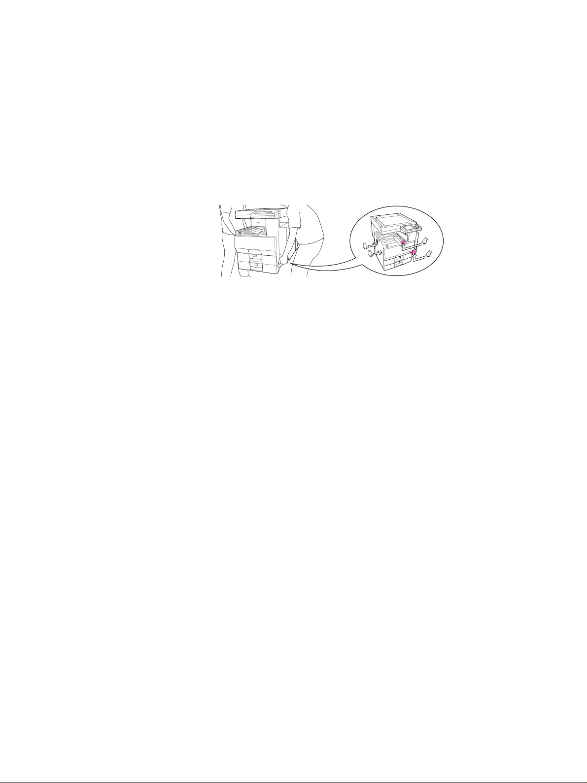
1. T ransportation/Installation
• When transporting/installing the copier, employ two persons and be sure to use the positions as
indicated below .
The copier is quite heavy and weighs approximately 73kg (161lb), therefore pay full attention when
handling it.
• Be sure to use a dedicated outlet with AC 115V or 120V/15A (220V, 230V , 240V/10A) or more f or
its power source.
• The copier must be grounded for saf ety.
Never g round it to a gas pipe or a water pipe.
• Select a suitable place for installation.
Av oid excessive heat, high humidity, dust, vibration and direct sunlight.
• Also provide proper ventilation as the copier emits a slight amount of ozone .
• To insure adequate working space for the copying operation, keep a minimum clearance of
80 cm (32”) on the left, 80 cm (32”) on the right and 10 cm (4”) in the rear.
• The socket-outlet shall be installed near the copier and shall be easily accessible.
2. Service of Machines
• Basically, be sure to turn the main switch off and unplug the power cord during service.
• Be sure not to touch high-temperature sections such as the exposure lamp, the fuser unit, the
damp heater and their periphery.
• Be sure not to touch high-voltage sections such as the chargers, high-voltage transformer, IH
control circuit, exposure lamp control inverter, inverter for the LCD backlight and power supply
unit. Especially, the board of these components should not be touched since the electirc charge
may remain in the condensers, etc. on them even after the power is turned OFF.
• Be sure not to touch rotating/operating sections such as gears, belts, pulleys, fan, etc.
• Be careful when removing the covers since there might be the parts with very sharp edges underneath.
• When servicing the machines with the main switch turned on, be sure not to touch live sections
and rotating/operating sections. Av oid exposure to laser radiation.
• Use suitable measuring instruments and tools.
• Av oid exposure to laser radiation during servicing.
− Av oid direct exposure to the beam.
− Do not insert tools, parts, etc. that are reflective into the path of the laser beam.
− Remove all watches, rings, bracelets , etc. that are reflective.
Page 3

3. Main Service Parts for Safety
• The breaker , door switch, fuse, thermostat, thermofuse, thermistor, etc. are particularly important
for safety. Be sure to handle/install them properly.
4. Cautionary Labels
• During servicing, be sure to check the rating plate and the cautionary labels such as “Unplug the
power cord during service”, “Hot area”, “Laser w arning label” etc. to see if there is any dirt on their
surface and whether they are properly stuck to the copier.
5. Disposition of Consumable Parts/Packing Materials
• Regarding the recovery and disposal of the copier, supplies , consumable parts and packing materials, it is recommended to follow the relevant local regulations or rules.
6. When parts are disassembled, reassembly is basically the reverse of disassembly unless
otherwise noted in this manual or other related documents. Be careful not to reassemble
small parts such as screws, washers, pins, E-rings, star washers in the wrong places.
7. Basically , the machine should not be operated with an y parts removed or disassembled.
8. Precautions Against Static Electricity
• The PC board must be stored in an anti-electrostatic bag and handled carefully using a wristband,
because the ICs on it may become damaged due to static electricity.
Caution: Before using the wristband, pull out the power cord plug of the copier and make
sure that there are no uninsulated charged objects in the vicinity .
Caution : Dispose of used batteries and RAM-ICs including lithium batteri es
according to the manufacturer’s instructions.
Attention : Se débarrasser de batteries et RAM-ICs usés y compris les batteries en
lithium selon les instructions du fabricant.
V orsic ht : Entsorgung des gebrauchten Batterien und RAM-ICs (inklusive
der Lithium-Batterie) nach Angaben des Herstellers.
Page 4

1. ERROR CODE AND SELFDIAGNOSIS
2. ADJUSTMENT
3. PREVENTIVE MAINTENANCE
(PM)
4. PRECAUTIONS FOR STORING
/ HANDLING SUPPLIES AND
PARTS
5. TROUBLESHOOTING
6. UPDATING THE FIRMWARE
7. WIRE HARNESS
CONNECTION DIAGRAMS
Page 5

CONTENTS
1. ERROR CODE AND SELF-DIA GNOSIS ..................................................................................... 1- 1
1.1 Error Code ............................................................................................................................. 1-1
1.2 Self-Diagnosis Modes ............................................................................................................ 1-6
1.2.1 Input check (test mode 03) ....................................................................................... 1-8
1.2.2 Output check (test mode 03) ....................................................................................1-13
1.2.3 T est print mode (test mode 04) ................................................................................. 1-15
1.2.4 Adjustment mode (05)............................................................................................... 1-16
1.2.5 Setting mode (08) .....................................................................................................1-22
2. ADJUSTMENT............................................................................................................................ 2- 1
2.1 Formatting the Hard Disk ....................................................................................................... 2-1
2.2 Adjustment of Auto-Toner Sensor........................................................................................... 2-2
2.3 Dimensional Adjustment of Copied Image.............................................................................. 2- 4
2.3.1 Overview .................................................................................................................. 2-4
2.3.2 Paper alignment........................................................................................................ 2-6
2.3.3 Printer related adjustment ......................................................................................... 2- 7
2.3.4 Scanner related adjustment ...................................................................................... 2-11
2.4 Image Quality Adjustment...................................................................................................... 2-18
2.4.1 Image density ........................................................................................................... 2-18
2.4.2 Sharpness(HPF) adjustment ..................................................................................... 2-19
2.4.3 Gamma slope adjustment ......................................................................................... 2-19
2.4.4 Setting for the range correction ................................................................................. 2-20
2.5 High-Voltage Adjustment........................................................................................................ 2-21
2.6 Adjustment of Developer Unit ................................................................................................ 2-27
2.6.1 Adjustment of the doctor-sleeve gap......................................................................... 2-27
2.6.2 Adjustment of the developer polarity position............................................................ 2-29
2.7 Adjustment of Scanning Section............................................................................................ 2-30
2.7.1 Adjustment of carriages ............................................................................................ 2-30
2.7.2 Lens unit................................................................................................................... 2-3 4
2.8 Adjustment of Angle of the Printed Image.............................................................................. 2-37
2.9 Adjustment of Sidewa ys De viation of Sheet Caused by P aper F eeding.................................. 2-38
2.10 Key Copy Counter (MU-8, MU-10) .......................................................................................... 2-39
3. PREVENTIVE MAINTENANCE (PM) ......................................................................................... 3- 1
3.1 Maintenance Performed Every 150,000(DP4500) and
116,000 Copies (DP3500) ................................................................................................... 3- 1
3.2 Maintenance Performed Every 450,000(DP4500) and
348,000 Copies (DP3500) ................................................................................................... 3- 1
3.3 Cleaning the Units Which Have Processed 75,000 Copies (DP4500)/58,000 Copies (DP3500).. 3-1
3.4 Preventive Maintenance Checklist ......................................................................................... 3- 1
I October 2000 © T OSHIBA TECDP4500/3500 CONTENTS
Page 6

3.5 PM Kit ................................................................................................................................... 3-10
3.6 Jig List...................................................................................................................................3-11
4. PRECA UTIONS FOR STORING / HANDLING SUPPLIES AND PARTS ....................................4- 1
4.1 Precautions for Storing TOSHIBA Supplies............................................................................ 4-1
4.2 Checking and Cleaning of Photoconductive Drum .................................................................. 4- 1
4.3 Checking and Cleaning of Drum Cleaning Blade..................................................................... 4-2
4.4 Checking and Replacement of Pressure Roller Cleaning Roller .............................................. 4- 3
4.5 Checking and Cleaning of Fuser Roller and Pressure Roller ................................................... 4- 3
5. TROUBLESHOOTING ................................................................................................................ 5- 1
5.1 Diagnosis and Prescription for Each Error Code..................................................................... 5-1
5.1.1 Paper transport jam ..................................................................................................5- 1
5.1.2 Paper misf eeding ...................................................................................................... 5-10
5.1.3 Cover open jam ........................................................................................................ 5-17
5.1.4 T ransport jam (ADU and other area).......................................................................... 5-23
5.1.5 T ransport jam (RADF) ............................................................................................... 5-27
5.1.6 Paper jam in finisher ................................................................................................. 5-28
5.1.7 Drive system related service call .............................................................................. 5-48
5.1.8 Paper feeding system related service call................................................................. 5-49
5.1.9 Scanning system related service call........................................................................ 5-55
5.1.10 Fuser unit related service call ................................................................................... 5-57
5.1.11 Communication related service call .......................................................................... 5-60
5.1.12 ADF related service call............................................................................................ 5-63
5.1.13 Laser optical unit related service call ........................................................................ 5-65
5.1.14 Finisher related service call ...................................................................................... 5-66
5.1.15 Service call for others............................................................................................... 5-94
5.2 Troubleshooting for the Image ................................................................................................ 5-95
5.3 Troubleshooting for the Blown Fuse........................................................................................ 5-117
6. UPDA TING THE FIRMWARE ...................................................................................................... 6-1
6.1 Installing Software for Firmware Update ................................................................................. 6- 2
6.1.1 Outline ...................................................................................................................... 6- 2
6.1.2 Requirements ........................................................................................................... 6-2
6.1.3 Dial-up networking function ....................................................................................... 6-3
6.1.4 Installing dial-up networking ...................................................................................... 6-7
6.1.5 Setting dial-up networking ......................................................................................... 6-9
6.1.6 Installing software for FTP server ............................................................................. 6-13
6.2 Operation Procedure in [3][9] Mode........................................................................................ 6- 17
6.2.1 Outline ...................................................................................................................... 6-17
6.2.2 Preparation ...............................................................................................................6-17
6.2.3 Updating firmware ..................................................................................................... 6-19
IIOctober 2000 © TOSHIBA TEC DP4500/3500 CONTENTS
Page 7

6.2.4 Display .....................................................................................................................6-25
6.3 Updating the Firmware Using the Downloading Jig ................................................................. 6-29
6.3.1 System firmware....................................................................................................... 6-30
6.3.2 Engine firmware ........................................................................................................ 6-37
7. WIRE HARNESS CONNECTION DIAGRAMS ............................................................................ 7- 1
7.1 AC Wire Harness....................................................................................................... 7-2
7.2 DC Wire Harness ............................................................................................. Appendix
III October 2000 © TOSHIBA TECDP4500/3500 CONTENTS
Page 8
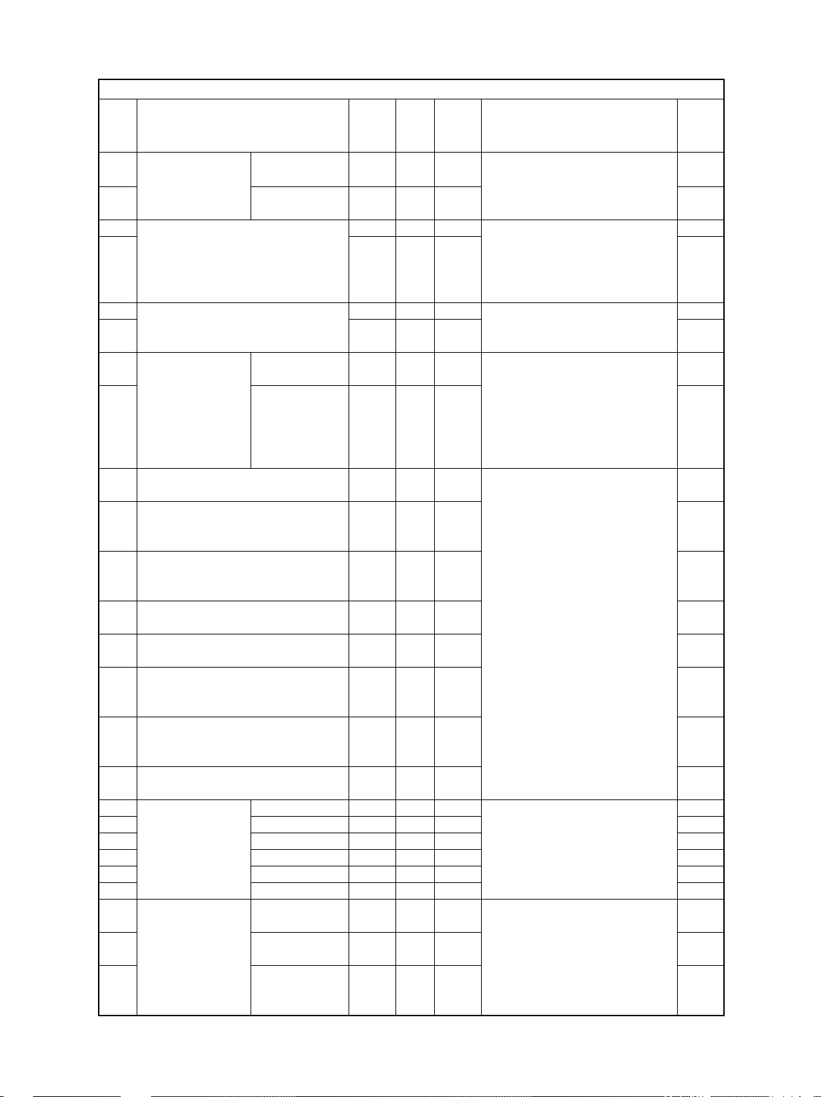
1. ERROR CODES AND SELF-DIAGNOSIS
1.1 Error Code
One of the following error codes is displayed instead of the set number while the [CLEAR/STOP] key and the
digital key “8” are pressed simultaneously when the “CLEAR PAPER” or “CALL SERVICE” symbol is flashing.
Group
Paper transport jam inside the E01 Leading edge of paper not reaching the exit sensor
copier (1) E02 Trailing edge of paper not passing the exit sensor
Paper misfeeding E11 ADU misfeeding
Paper transport jam inside the E20 Paper fed from the upper cassette
copier (2) not reaching the registration sensor
December 2000 © TOSHIBA TEC 1 - 1
Error Code
E03 Paper remaining inside the copier at power ON
E09 HDD is abnormal
(paper not reaching the registration sensor)
E12 Bypass misfeeding
(paper not reaching the registration sensor)
E13 Upper cassette misfeeding
(paper not reaching the upper feed sensor)
E14 Lower cassette misfeeding
(paper not reaching the lower feed sensor)
E15 PFP upper cassette misfeeding
(paper not reaching the PFP upper feed sensor)
E16 PFP lower cassette misfeeding
(paper not reaching the PFP lower feed sensor)
E19 LCF misfeeding
(paper not reaching the LCF feed sensor)
E21 Paper fed from the lower cassette
not reaching the registration sensor
E22 Paper fed from the lower cassette
not reaching the upper feed sensor
E30 Paper fed from the PFP upper cassette
not reaching the registration sensor
E31 Paper fed from the PFP upper cassette
not reaching the upper feed sensor
E32 Paper fed from the PFP upper cassette
not reaching the lower feed sensor
E33 Paper fed from the PFP lower cassette
not reaching the registration sensor
E34 Paper fed from the PFP lower cassette
not reaching the upper feed sensor
E35 Paper fed from the PFP lower cassette
not reaching the lower feed sensor
E36 Paper fed from the PFP lower cassette
not reaching the PFP upper feed sensor
E3C Paper fed from the LCF
not reaching the registration sensor
E3D Paper fed from the LCF
not reaching the upper feed sensor
E3E Paper fed from the LCF
not reaching the lower feed sensor
Machine Status
DP4500/3500 ERROR CODES AND SELF-DIAGNOSIS
Page 9
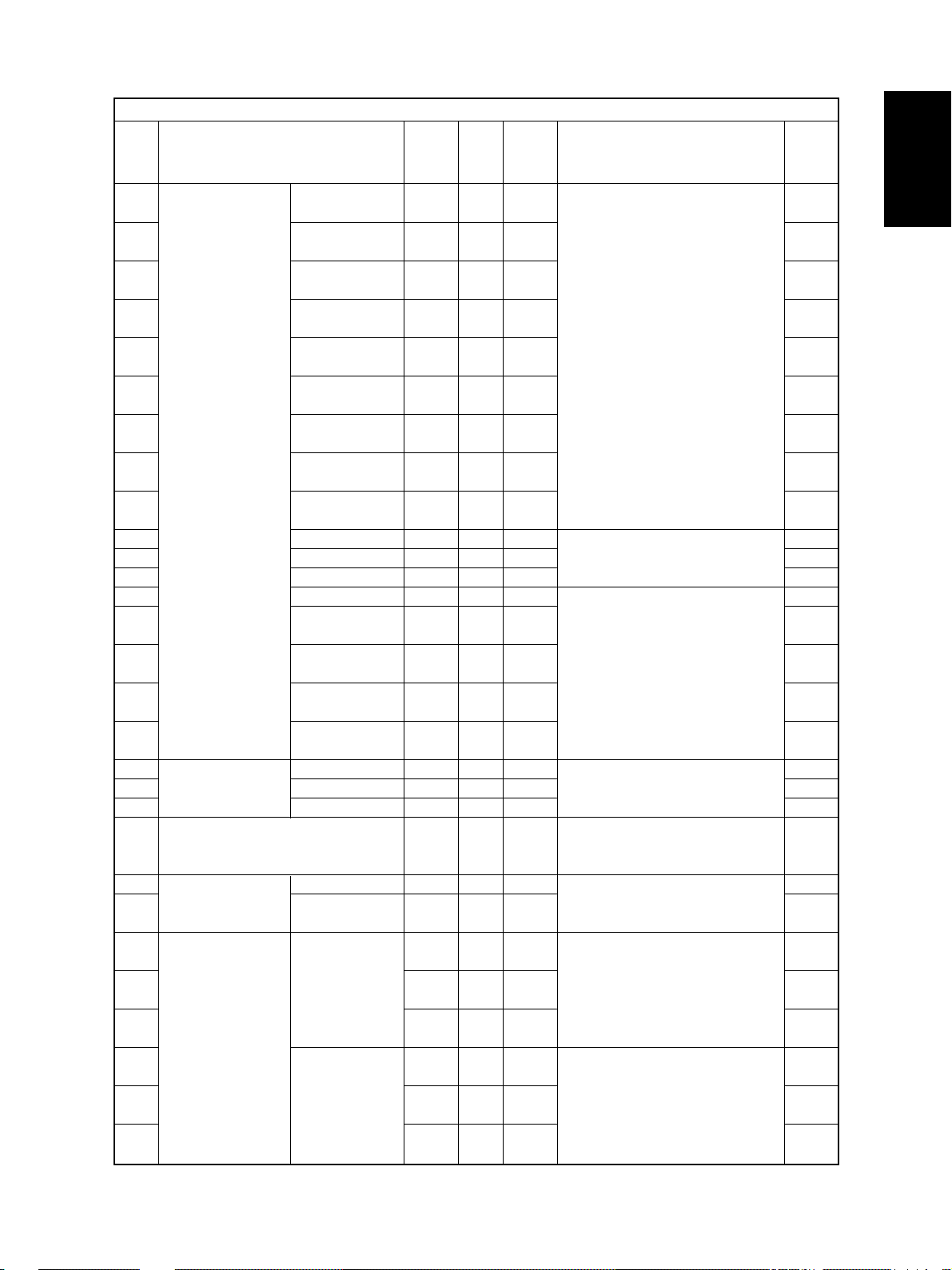
Group
Cover open jam E40 Jam access cover opened during printing
Transport jam (ADU and other area) E51 ADU stack jam (paper not reaching the ADU entrance sensor)
Transport jam (RADF) E71 Original feeding jam
Paper jam in finisher E91 Leading edge of paper not reaching the relay unit transport
Paper transport jam inside the EB5 Paper left on the transport path due to multiple feeding
copier (3) EB6 Paper left on the transport path due to multiple feeding
Drive system related service call C0 1 Main motor is abnormal
Error Code
E41 Front cover opened during printing
E42 PFP side cover opened during printing
E43 ADU opened during printing
E44 Side cover opened during printing
E45 LCF side cover opened during printing
E48 Relay unit opened during printing
E52 ADU transport jam (paper not reaching the ADU exit sensor)
E55 Paper remaining on the transport path when CRUN is OFF
E72 Original transport jam
E73 Original discharging jam
E74 Original reversing jam
sensor-1
E92 Trailing edge of paper not passing the relay unit transport sen-
sor-1
E93 Leading edge of paper not reaching the relay unit transport
sensor-2
E94 Trailing edge of paper not passing the relay unit transport sen-
sor-2
E9F Punching jam
EA1 Finisher paper transport delay jam
EA2 Finisher paper transport stop jam
EA3 Paper remaining inside the finisher at power ON
EA4 Finisher front door opened during printing
EA5 Finisher stapling jam
EA6 Finisher early arrival jam
EA7 Stack transport jam before stapling
EA8 Saddle stitcher stapling jam
EA9 Saddle stitcher door opened during printing
EAA Paper remaining at the saddle stitcher at power ON
EAB Saddle stitcher paper transport stop jam
EAC Saddle stitcher paper transport delay jam
EAD Print end command time-out jam
EAE Receiving time time-out jam
EAF Stapled stack transport jam
EB3 Ready time time-out jam
Machine Status
DP4500/3500 ERROR CODES AND SELF-DIAGNOSIS
1 - 2 December 2000 © TOSHIBA TEC
Page 10

Group
Paper feeding system related service call
Scanning system related service call C2 6 Peak detection error
Fuser unit related service call C4 1 Thermistor or heater is abnormal at power ON
Communication related service call C55 ADF I/F is abnormal
RADF related service call C7 1 ADF feed motor is abnormal
Laser optical unit related service call CA 1 Polygonal motor is abnormal
Error Code
C0 4 PFP motor is abnormal
(paper can be fed from cassettes other than PFP cassette)
C1 3 Upper cassette tray is abnormal (paper can be fed from the
cassettes other than the copier cassettes)
C1 4 Lower cassette tray is abnormal (paper can be fed from the
cassettes other than the copier cassettes)
C1 5 PFP upper cassette tray is abnormal (paper can be fed from
the cassettes other than the PFP upper cassette)
C16 PFP lower cassette tray is abnormal (paper can be fed from the
cassettes other than the PFP lower cassette)
C1 8 LCF tray-up motor is abnormal
(paper can be fed from the cassettes other than the LCF
cassette)
C1A LCF end fence motor is abnormal
(paper can be fed from the cassettes other than the LCF
cassette)
C1B LCF motor is abnormal
(paper can be fed from the cassettes other than the LCF
cassette)
C2 7 Carriage home position sensor not going OFF within a fixed
time
C28 Carriage home position sensor not going ON within a fixed
time
C4 3 Thermistor is abnormal after abnormality judgment
C4 4 Fuser is abnormal after abnormality judgment
C45 Side thermistor is abnormal after the copier has become ready
C4 7 IH power voltage is abnormal/IH initialization error
C4 8 IGBT high temperature
C4 9 IH circuit or coil is abnormal
C5 7 Communication error between main CPU and IPC board
C5 8 Communication error between IPC board and finisher
F07 Communication error between SYS board and LGC board
F11 Communication error between SYS board and SLG board
C7 3 EEPROM initialization error
C7 4 Reverse sensor adjustment error
C8 1 Fan motor is abnormal
C8 2 Read sensor adjustment error
C8 3 Original length sensor adjustment error
CA2 H-Sync detection error
Machine Status
December 2000 © TOSHIBA TEC 1 - 3
DP4500/3500 ERROR CODES AND SELF-DIAGNOSIS
Page 11
Group
Finisher related service call CB1 Feed motor is abnormal
Service call for others C 9 4 Main CPU is abnormal
Error Code
CB2 Delivery motor is abnormal
CB3 Tray lift motor is abnormal
CB4 Alignment motor is abnormal
CB5 Staple motor is abnormal
CB6 Stapler shift motor is abnormal
CB7 Height sensor is abnormal
CB8 Backup RAM data are abnormal
CB9 Saddle stitcher paper pushing plate motor is abnormal
CBA Saddle stitcher stitch motor (front) is abnormal
CBB Saddle stitcher stitch motor (rear) is abnormal
CBC Saddle stitcher alignment motor is abnormal
CBD Saddle stitcher guide motor is abnormal
CBE Saddle stitcher paper folding motor is abnormal
CBF Saddle stitcher paper positioning plate motor is abnormal
CC 0 Saddle stitcher sensor connector connection error
CC 1 Saddle stitcher microswitch error
CC 2 Communication error between finisher and saddle stitcher
CC 3 Stack processing motor is abnormal
CC 4 Swing motor is abnormal
CC 5 Horizontal registration motor is abnormal
CC 6 Punch motor is abnormal
CC 8 Front jogging motor is abnormal
CC 9 Upper stack tray lift motor is abnormal
CCA Lower stack tray lift motor is abnormal
CCB Rear jogging motor is abnormal
F10 HDD initialization error
Machine Status
DP4500/3500 ERROR CODES AND SELF-DIAGNOSIS
1 - 4 December 2000 © TOSHIBA TEC
Page 12
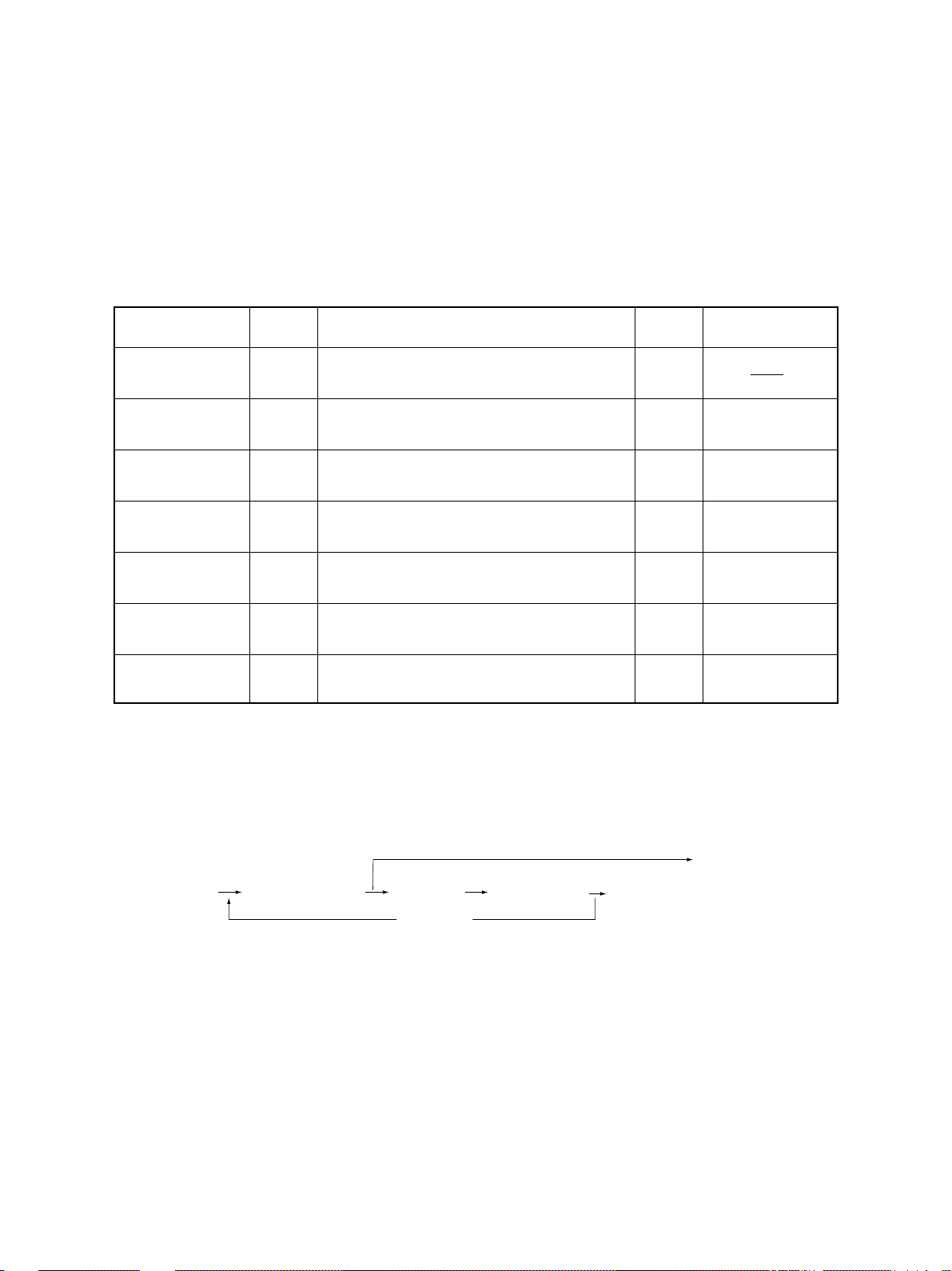
<<Error history (08-253)>>
(Example of display)
Copy mode
A Paper source
0: Not selected 1: Bypass feeding 2: LCF 3: PFP(U) 4: Not used 5: PFP(L) 6: ADU feeding
7: Upper cassette 8: Lower cassette
B Paper size code
0: Not selected 1: A5-R 2: ST-R 3: LT 4: A4 5: B5-R 6: LT-R 7: A4-R 8: O THER/UNIV 9: B5
A: FOL/COM B: LG C: B4 D: LD E: A3 F: 13'LG G: 8.5*8.5 H: 8K I:16K J:16K-R
C Sort mode/Staple mode
0: Not selected 1: Group 2: Sort 7: Staple (stapling one corner -1) 8: Staple (stapling 2 places)
9: Staple (stapling one corner -2) A: Saddle stitch
D ADF mode
0: Not used 1: A UTO FEED (SADF) 2: STACK FEED
E APS/AMS mode
0: Not selected 1: APS 2: AMS
F Duplex mode
0: Not selected 1: BOOK 2: Two-sided/Single-sided 4: Two-sided/Duplex 8: Single-sided/Duplex
G Not used
0: Not used
H Image shift
0: Not used 1: BOOK 2: LEFT 3: RIGHT
I Editing
0: Not used 1: Masking 2: Trimming 3: Mirror image 4: Negative/Positive
J Edge erasing/Dual-page
0: Not used 1: Edge erase 2: Dual-page 3: Edge erase & Dual-page
K Not used
0: Not used
L Function
0: Not used 1: Copying 2: Fax input 3: Fax printing 4: LAN printer 5: DSS
EA1
Error code
3 digits
0 0 1 2 2 6 1 7 5 7 3 2
YYMMDDHHMMSS
with its last 2 digits)
6 4
MMM
3 digits
3 digits12 digits (Year indicated
6 4
NNN
2 3 6 2 1 0 0 0 0 0 0 0
ABCDEFGHIJKL
12 digits
Reproduction ratio
MMM Primary scanning reproduction ratio
Shown in hexadecimal
NN N Secondary scanning reproduction ratio
Shown in hexadecimal
The latest 8 error data can be displayed in the setting mode (08-253).
December 2000 © TOSHIBA TEC 1 - 5
DP4500/3500 ERROR CODES AND SELF-DIAGNOSIS
Page 13
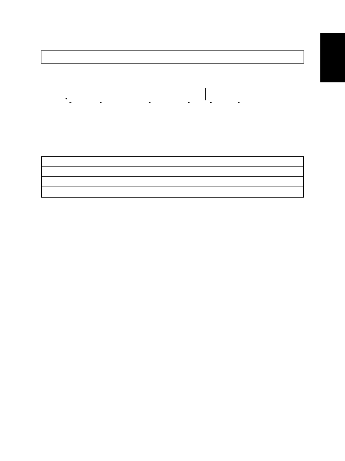
1.2 Self-Diagnosis Modes
Since this copier is designed to cope with multifunctions such as those of a network printer and DSS, there
are many setting items which are related to each other in the self-diagnosis modes.
Malfunctions such as machine locking can be caused by the internal structural problem of the program
when a normal operation is attempted by pressing [0] and [9] simultaneously or [C/S] on the control panel
subsequently to the adjustment.
Therefore, turn OFF the power after using the self-diagnosis mode for adjustment after unpacking, service
or prev entive maintenance , and then leav e the machine to the customer .
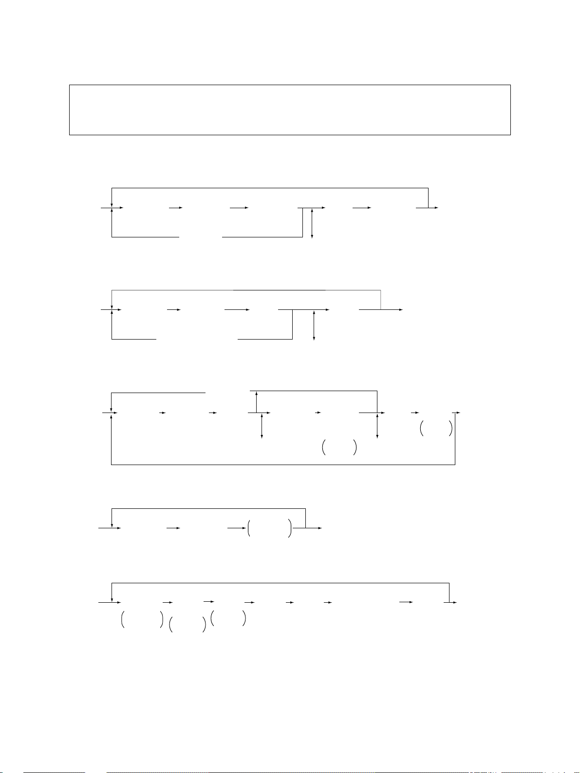
Mode
Whole control panel
items lighting mode
Test mode
Test print mode
Adjustment mode
Setting mode
List printing mode
Unit replacement
mode
Note: To enter the desired mode, turn ON the power while two digital keys designated to each mode (e.g. [0] and
[5]) are pressed simultaneously.
Keys to
press exit
[0]+[1]+
[POWER]
[0]+[3]+
[POWER]
[0]+[4]+
[POWER]
[0]+[5]+
[POWER]
[0]+[8]+
[POWER]
[9]+[ST AR T]
+[ POWER]
[6]+[ST ART]
+[ POWER]
All LEDs on the control panel are lit, and all
the LCD pixels flash.
Checks the status of input/output signals.
Outputs the test patterns.
Adjusts various items.
Sets various items.
Prints out the lists for the codes 05 and 08.
Performs auto-toner adjustment and clears
the process counters.
Function
Keys to
[C/S]or
[0]+[9]
[0]+[9]
[0]+[9]
[0]+[9]
[0]+[9]
[POWER]
OFF
[POWER]
OFF
Display
100% C
TEST MODE
100% P A4
TEST PRINT
100% A A4
TEST MODE
100% D
TEST MODE
100% L A4
LIST PRINT
100% K
TEST MODE
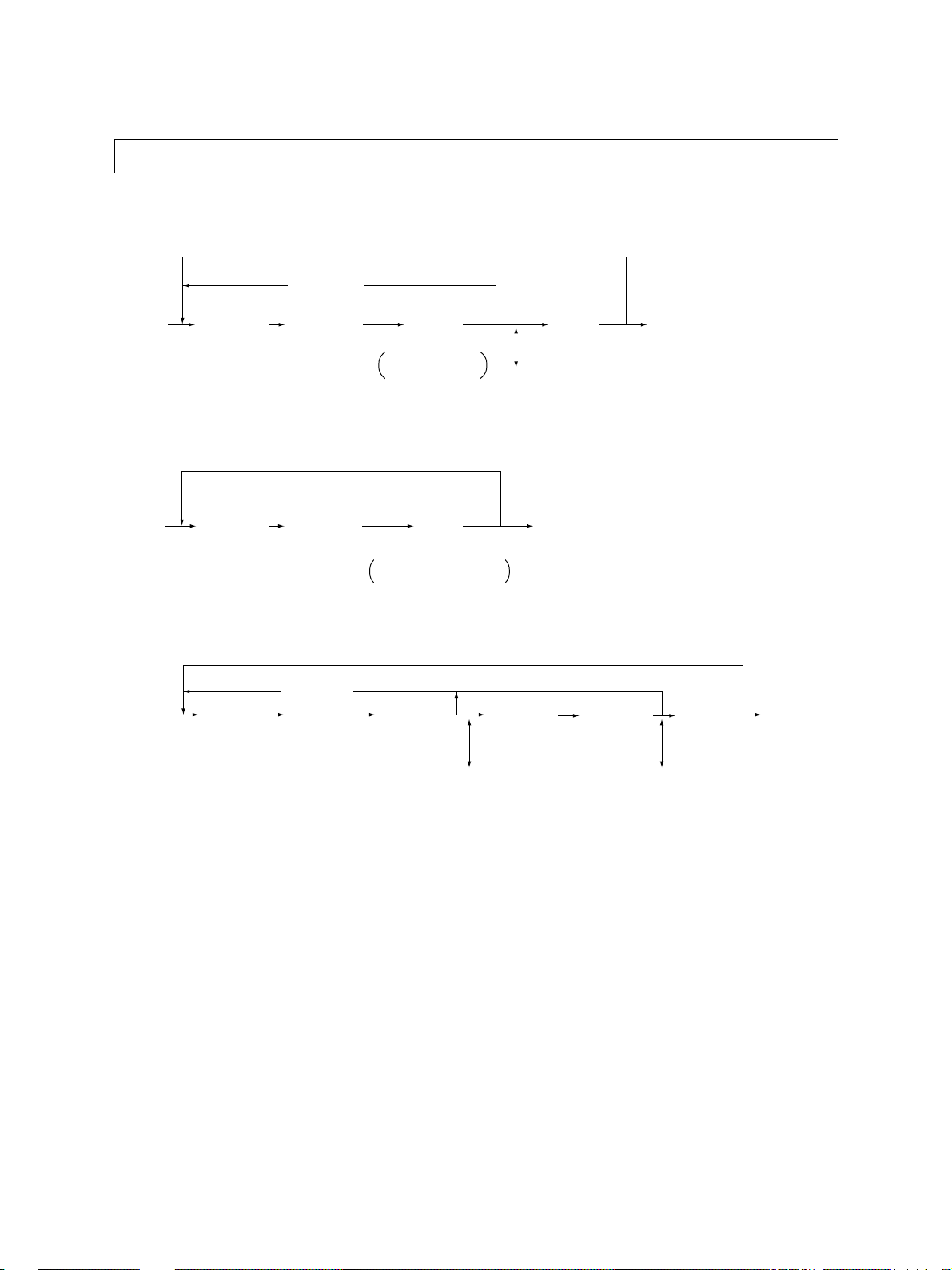
<Operation procedure>
• Whole control panel items lighting mode (01):
[0] [1]
[POWER]
Notes: 1. The mode can be canceled only by pressing the [C/S] key during the key check.
2. Key Check Keys with LED (Press to turn OFF the LED)
DP4500/3500 ERROR CODES AND SELF-DIAGNOSIS
(All control
panel LEDs lit)
Keys without LED (Press to display the message on the control panel)
[START]
[START]
(Key check) [C/S] (Exit)
1 - 6 December 2000 © TOSHIBA TEC
[C/S] or [0] [9]
(Exit)
Page 14
• Test mode (03): Refer to “1.2.1 Input check (test mode 03)” and “1.2.2 Outpout check (test mode 03)”.
• Test print mode (04): Refer to “1.2.3 Test print mode (04)”.
• Adjustment mode (05): Refer to “1.2.4 Adjustment mode (05)”.
• List print mode
[9] [START]
[POWER]
(code)
101:05 adjustment mode
(List starts to be printed)
102: 08 setting mode
• Unit replacement mode
[6] [START]
[POWER]
(code) [POWER] OFF
1: Auto-toner adjustment
2: Drum life counter resetting (08-401)
3: Resetting of the copier running time counter (08-402) and fuser unit counter (08-403)
4: Resetting of the separation charger life counter (08-497)
[STA RT]
(Operation started)
• Setting mode (08): Refer to “1.2.5 Setting mode (08)”.
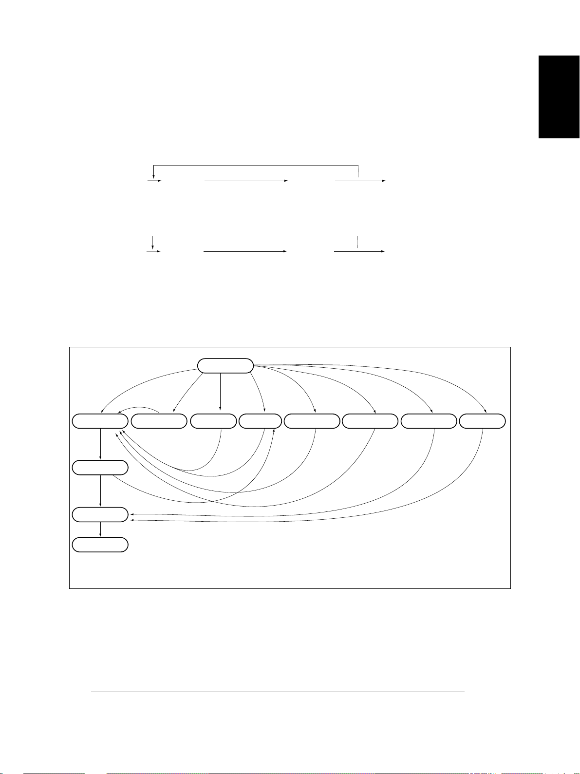
[POWER] ON
Warming up
Normal
[C/S]
Whole control
panel items lit
*2
[0][1] [0][3]
Test mode
[0][5]
Adjustment mode
[0][9][0][9]
Setting mode
[0][9]
[STA RT]
[0][8] [0][4] [9][S]
T est print mode
[0][9]
[POWER] OFF
List print mode
[6][S]
Unit replacement
mode
Standby
*1
[0][5]
[POWER] OFF
*3
To user
[S]: START key
[C/S]: CLEAR/STOP key
State transition diagram of self-diagnosis mode
*1 Only when the copier is put into the adjustment mode by turning ON the power while the digital keys
[0] and [5] are pressed simultaneously and then becomes standby state by pressing [0] and [9]
simultaneously, it can go back to the adjustment mode by the pressing of [0] and [5] simultaneously.
*2 In the “whole control panel items lighting mode”, copying is disabled. Enter the standby state by
pressing [0] and [9] simultaneously or [C/S] key to perform copying.
*3 Turn OFF the power after using the self-diagnosis mode, and leave the copier to the user .
December 2000 © TOSHIBA TEC 1 - 7
DP4500/3500 ERROR CODES AND SELF-DIAGNOSIS
Page 15
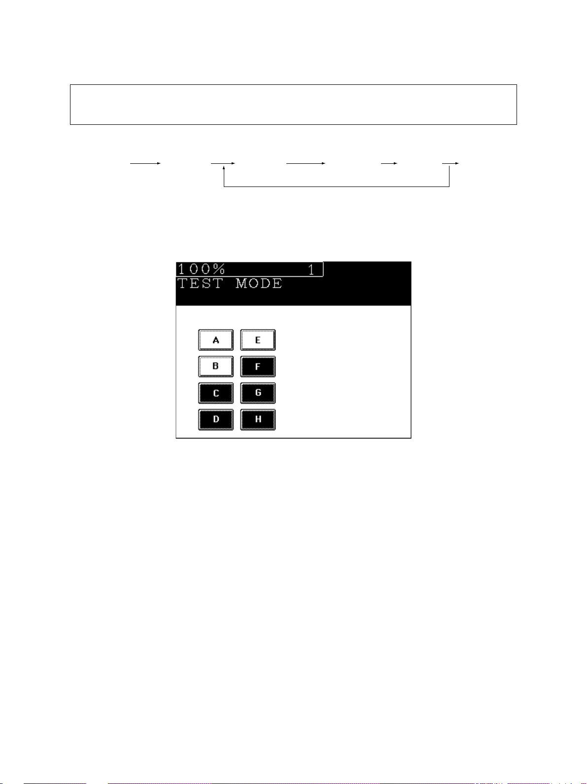
1.2.1 Input check (test mode 03)
The state of each input signal can be checked b y pressing the [FAX] key and the digital keys in the
test mode (03).
<Operation procedure>
[0] [3]
[POWER]
Note: Initialization is performed before the copier enters the test mode.
[ST ART] ([F AX]) [Digital key] (LCD ON) [0] [9]
(Exit)
[Example of display during input check]
Items to be checked and the state of the copier with the icons [A] to [H] displayed in black are listed on the
following pages.
DP4500/3500 ERROR CODES AND SELF-DIAGNOSIS
1 - 8 December 2000 © TOSHIBA TEC
Page 16
[FAX] key: OFF ( [FAX] LED: OFF)
Digital
key with black icon
Icon Items to check
A—
B LCF connection Not connected
C—
[1]
[2]
[3]
[4]
[5]
[6]
D Bypass feed sensor Paper does not exist
E ADU connection Not connected
F ADU opening/closing switch ADU opened
G ADU exit sensor There is paper
H ADU entrance sensor There is paper
A—
B—
C PFP upper cassette paper-stock sensor Paper is almost finished
D PFP upper feed sensor There is paper
E PFP connection Not connected
F PFP side cover opening/closing switch Cover opened
G PFP upper cassette paper-empty sensor No paper
H PFP upper cassette tray-up sensor Tray at upper limit position
A LCF tray bottom sensor Tray at bottom position
B LCF paper mis-insertion detection sensor Paper not inserted properly
C—
D—
E—
F—
G—
H LCF feed side paper-stock sensor Paper is almost finished
A—
B—
C PFP lower cassette paper-stock sensor Paper is almost finished
D PFP lower feed sensor There is paper
E PFP motor rotation condition (motor is being rotated in the output check (03)) Abnormal rotation
F—
G PFP lower cassette paper-empty sensor No paper
H PFP lower cassette tray-up sensor Tray at upper limit position
A LCF end fence home position sensor Fence at home position
B LCF end fence stop position sensor Fence at stop position
C LCF standby side paper-empty sensor No paper
D LCF side cover opening/closing switch Cover closed
E LCF motor rotation condition (motor is being rotated in the output check (03)) Abnormal rotation
F LCF tray-up sensor Tray at upper limit position
G LCF feed sensor No paper
H LCF feed side paper-empty sensor No paper
A—
B—
C—
D—
E Upper feed sensor There is paper
F—
G Upper cassette paper-empty sensor No paper
H Upper cassette tray-up sensor Tray at upper limit position
Copier state
December 2000 © TOSHIBA TEC 1 - 9
DP4500/3500 ERROR CODES AND SELF-DIAGNOSIS
Page 17
Digital
key with black icon
Icon Items to check
A—
B—
C—
[7]
[8]
[9]
[0]
D—
E Lower feed sensor There is paper
F—
G Lower cassette paper-empty sensor No paper
H Lower cassette tray-up sensor Tray at upper limit position
A Bypass feed paper width sensor-3 See table 1.
B Bypass feed paper width sensor-2 See table 1.
C Bypass feed paper width sensor-1 See table 1.
D Bypass feed paper width sensor-0 See table 1.
E—
F—
G—
H PFP upper cassette detection sensor No cassette
A—
B—
C—
D PFP lower cassette detection sensor No cassette
E—
F—
G Upper cassette detection sensor No cassette
H Upper cassette paper-stock sensor Paper is almost finished
A—
B—
C—
D LCF cassette detection switch No cassette
E—
F—
G Lower cassette detection sensor No cassette
H Lower cassette paper-stock sensor Paper is almost finished
Copier state
Table 1. Relation between the state of the bypass feed paper width sensor and paper siz e (width).
Bypass paper width sensor
3210
0 1 1 1 A3/LD
1 0 1 1 A4-R/LT-R
1 1 0 1 A5-R/ST-R
1 1 1 0 Card size
0 0 1 1 B4-R/LG
1 0 0 1 B5-R
DP4500/3500 ERROR CODES AND SELF-DIAGNOSIS
Paper width size
1 - 10 December 2000 © TOSHIBA TEC
Page 18

[FAX] key: ON ([FAX] LED: ON)
Digital
key with black icon
Icon Items to check
A—
B—
C—
[1]
[2]
[3]
[4]
[5]
D IPC board connection Not connected
E—
F Polygonal motor rotation condition (motor is being rotated in the output check (03)) Abormal rotation
G Toner cartridge detection switch OFF
H 24V power supply OFF
A Registration sensor There is paper
B Exit sensor There is paper
C Auto-toner sensor connection Not connected
D Front cover switch Cover opened
E—
F—
G Side door switch Side cover opened
H Main motor rotation condition (motor is being rotated by in the output check (03)) Abormal rotation
A—
B Key copy counter connection Not connected
C Toner bag full detection sensor Toner is full
D Fuser unit connection Unit connected
E Relay unit transport sensor-2 No paper
F Relay unit opening/closing switch Cover opened
G—
H Relay unit paper full detection sensor Paper not full
A—
B—
C—
D—
E—
F—
G Relay unit installation Not installed
H Relay unit transport sensor-1 No paper
A—
B—
C—
D—
E—
F RADF connection RADF connected
G Platen sensor Platen cover opened
H Scanner carriage home position sensor Home position
Copier state
December 2000 © TOSHIBA TEC 1 - 11
DP4500/3500 ERROR CODES AND SELF-DIAGNOSIS
Page 19
Digital
key with black icon
Icon Items to check
A—
B—
C—
[6]
[7]
[8]
[9]
[0]
D APS sensor (APS-5/for A4 series) / (APS-6/for LT series) No original
E APS sensor (APS-4/for A4 series) No original
F APS sensor (APS-3) No original
G APS sensor (APS-2) No original
H APS sensor (APS-1) No original
A RADF tray sensor Original present
B RADF empty sensor Original present
C RADF jam access cover opening/closing switch Cover opened
D RADF opening/closing sensor RADF opened
E RADF exit sensor Original present
F RADF reverse sensor Original present
G RADF read sensor Original present
H RADF registration sensor Original present
A—
B—
C—
D—
E RADF original length sensor Original present
F RADF original width sensor-1 Original present
G RADF original width sensor-2 Original present
H RADF original width sensor-3 Original present
A—
B—
C—
D—
E—
F—
G—
H—
A—
B—
C—
D—
E—
F—
G—
H—
Copier state
DP4500/3500 ERROR CODES AND SELF-DIAGNOSIS
1 - 12 December 2000 © TOSHIBA TEC
Page 20

1.2.2 Output check (test mode 03)
State of the output signals can be checked by entering the codes in the following table in the test
mode 03.
<Operation procedure>
Group (1)
[0] [3]
[POWER]
(Code) [START ]
Operation
started
Code to stop
operation
[START]
Operation
stopped
[0] [9]
(Exit)
Warming up
Group (2)
[0] [3]
[POWER]
(Code)
[STAR T]
Operation
(One direction)
[C/S] [0] [9]
Test mode
standby
Warming up
(Exit)
Group (3)
[0] [3]
[POWER]
(Code) [START] [START] [C/S] [0] [9]
Operation
started
Operation
stopped
Test mode
standby
(Exit)
Warming
up
Group (4)
[0] [3]
[POWER]
Code Function Code Function Procedure
10 1 Main motor ON 15 1 Code 101 operation OFF 1
10 2 Toner motor ON 152 Code 102 operation OFF 1
10 3 Polygonal motor (600dpi) ON 1 53 Code 103 operation OFF 1
10 8 Registration clutch ON 15 8 Code 108 operation OFF 1
109 PFP motor ON 159 Code 109 operation OFF 1
11 0 ADU motor (215mm/s) ON 16 0 Code 110 operation OFF 1
11 8 Laser ON 1 68 Code 118 operation OFF 1
12 0 Exit motor ON / forward rotation 17 0 Code 120 operation OFF 1
12 1 Exit motor ON / reverse rotation 17 1 Code 121 operation OFF 1
12 2 LCF motor ON 17 2 Code 122 operation OFF 1
201 Upper cassette feed clutch ON/OFF 3
202 Lower cassette feed clutch ON/OFF 3
20 3 Transport clutch (high speed) ON/OFF 3
204 Bypass feed clutch ON/OFF 3
20 5 Transport clutch (low speed) ON/OFF 3
20 6 LCF pickup solenoid ON/OFF 3
(Code)
[START]
[POWER] OFF
December 2000 © TOSHIBA TEC 1 - 13
DP4500/3500 ERROR CODES AND SELF-DIAGNOSIS
Page 21

Code Function Procedure
20 7 LCF end fence reciprocating movement 2
208 LCF end fence motor ON/OFF 3
209 LCF feed clutch ON/OFF 3
210 LCF transport clutch ON/OFF 3
211 RADF feed motor ON/OFF / forward rotation 3
212 RADF feed motor ON/OFF / reverse rotation 3
213 RADF read motor ON/OFF / forward rotation 3
214 RADF read motor ON/OFF / reverse rotation 3
215 RADF reverse motor ON/OFF / forward rotation 3
216 RADF reverse motor ON/OFF / reverse rotation 3
21 7 Sub-separation fan ON/OFF 3
21 8 Key copy counter count-up 2
21 9 Middle cooling fan ON/OFF 3
222 ADU clutch ON/OFF 3
225 PFP transport clutch ON/OFF 3
226 PFP upper cassette feed clutch ON/OFF 3
228 PFP lower cassette feed clutch ON/OFF 3
23 2 Relay unit gate solenoid ON/OFF 3
23 5 Discharge lamp ON/OFF 3
23 6 Exhaust fan (low speed) ON/OFF 3
23 7 Exhaust fan (high speed) ON/OFF 3
23 8 IH control board cooling fan / developer unit cooling fan ON/OFF 3
24 1 Fuser unit cooling fan ON/OFF 3
24 2 Upper cassette tray-up motor ON (tray raised) 2
24 3 Lower cassette tray-up motor ON (tray raised) 2
24 8 Developer bias +DC ON/OFF 3
24 9 Developer bias -DC1 ON/OFF 3
252 Main charger ON/OFF 3
25 3 Separation charger ON/OFF 3
25 5 Transfer guide bias ON/OFF 3
25 6 Transfer charger ON/OFF 3
261 Scanner motor ON (automatically stops at the limit position, speed can be changed by the ZOOM keys) 2
26 7 Scanner exposure lamp ON/OFF 3
26 8 Laser unit fan (high speed) ON/OFF 3
271 LCF tray-up motor UP/DOWN 2
27 8 PFP upper cassette tray-up motor ON (tray raised) 2
28 0 PFP lower cassette tray-up motor ON (tray raised) 2
29 4 RADF reverse solenoid ON/OFF 3
29 5 Power OFF mode 4
297 RADF fan motor ON/OFF 3
DP4500/3500 ERROR CODES AND SELF-DIAGNOSIS
1 - 14 December 2000 © TOSHIBA TEC
Page 22
1.2.3 T est print mode (test mode 04)
The built-in test pattern can be printed out by entering the following codes in the test print mode (04).
<Operation procedure>
[0] [4]
[POWER]
Note: An error code is displayed on the control panel if an error occurs in the process, but no recovery operation
Code Types of test pattern Remarks
11 1 Primary scanning direction, 33 gradation steps, error diffusion
11 3 Secondary scanning direction, 33 gradation steps, error diffusion
142 Grid pattern (Pattern width: 2 dots, Pitch: 10 mm)
(Code) [STAR T] [0] [9]
(Test pr int)
is performed.
Turn the power OFF and then back ON to clear the error.
[C/S]
Warming upOperation
(Exit)
December 2000 © TOSHIBA TEC 1 - 15
DP4500/3500 ERROR CODES AND SELF-DIAGNOSIS
Page 23
1.2.4 Adjustment mode (05)
Items in the adjustment code list on the following pages can be corrected or changed in this adjustment mode (05). Turn ON the power while the digital keys [0] and [5] are pressed sim ultaneously to
enter this mode.
<Procedure>
Group 1
[SET]
[0] [5]
[POWER]
[Digital key]
(Code)
[ST AR T] [0] [9]
[CANCEL]
[Digital key]
*[FC] key
(Enter a value)
(Corrects value)
or
[INTERRUPT]
(Stores value in RAM)
[C/S]
(Test copy)
[FAX]
(Exit)
* Press [FC] to enter “–”.
Group 2
[0] [5]
[POWER]
Group 3
[0] [5]
[POWER]
Group 4
[0] [5]
[POWER]
Group 5
[Digital key]
(Code)
[Digital key]
(Code)
[Digital key]
(Code)
[UP]
[START]
[C/S] or [CANCEL]
[CANCEL]
[START]
[ST ART] [0] [9]
[Digital key]
(Sub code)
or
[DOWN]
(Enter a value)
(Corrects value)
[START]
[C/S]
(Corrects value)
Automatic
adjustment
[SET]
or
[INTERRUPT]
(Stores value in RAM)
[RESET]
[Digital key]
* [FC] key
Enter a
value
(Exit)
[0] [9]
(Exit)
[SET]
or
[INTERRUPT]
(Stores value in
RAM)
[C/S]
(Corrects value)
* Press [FC] to enter “–”.
[F AX]
Test
copy
[0] [9]
(Exit)
[0] [5]
[POWER]
DP4500/3500 ERROR CODES AND SELF-DIAGNOSIS
[Cassette]
Selects
cassette
[Digital key]
Selects
output
pattern
1: Code 401, 421, 440~444
2: Code 445, 498
[F AX]
T est
copy
[Digital key]
(Code)
[ST ART]
(Adjustment)
1 - 16 December 2000 © TOSHIBA TEC
[Digital key]
(Enter a value)
(Stores value in RAM)
[SET]
or
[INTERRUPT]
[0] [9]
(Exit)
Page 24

Adjustment mode (05)
Code Items to adjust Mode
Automatic adjustment of auto-toner
200
sensor (Fuser heater ON)
201
Manual adjustment of auto-toner sensor initial value(Fuser heater ON)
Developer bias DC output adjustment
205
210
Main charger grid bias output
adjustment
T ransf er transformer DC output adjust-
221
ment/center value
Separation transformer AC output
231
adjustment/center value
Laser power adjustment
286
305
Adjustment of scanner secondary
scanning start position deviation
306
Adjustment of scanner primary scanning start position deviation
308
Distortion mode
340
Adjustment of scanner secondary
scanning reproduction ratio
354
Adjustment of for single-sided
RADF paper paper
alignment for double-sided
355
paper
Automatic adjustment of RADF sen-
356
sor and EEPROM initialization
357
Fine adjustment of RADF transport
speed
358
RADF sideways deviation adjustment
ALL – –
ALL 128 0~255
ALL 193 0~255
ALL 158 0~255
ALL 117 0~255
ALL 159 0~255
ALL 117 0~255
ALL 128 0~255
ALL 128 0~255
ALL – –
ALL 128 0~255
ALL 10 0~20
ALL 10 0~20
ALL – –
ALL 50 0~100
ALL 128 0~255
Default
Accept-
able Contents
value
- As the value increases, the sensor output increases correspondingly.
- The value starts changing
approx. 2 minutes after this adjustment was started and is automatically set in the range of 2.35
to 2.45V.
( chapter 2.2)
Adjustment value of auto-toner
sensor can be displayed.
As the value increases by “1”, output from the transformer increases
correspondingly. Remove the developer unit and install the service
jig to make adjustment. However,
the service jig is not necessary to
adjust the developer bias DC.
( chapter 2.5)
When the value increases by “1”,
the laser output increases correspondingly.
When the value increases by “1”,
the image shifts toward the leading
edge of paper by approx. 0.17mm.
When the value increases by “1”,
image shifts toward the rear side
of paper by approx. 0.0423mm.
Moves the carriages to the adjustment position.
( chapter 2.3.4)
When the value increases by “1”,
the reproduction ratio of the secondary scanning direction decreases by approx. 0.025%.
When the value increases by “1”,
the aligning amount increases by
approx. 0.5mm.
Perf orm the adjustment and initialization when the PC board or sensor of the RADF is replaced.
When the value increases by “1”,
the reproduction ratio of the secondary scanning direction on original fed from the RADF increases
by approx. 0.1%.
When the value increases by “1”,
the image of original fed from the
RADF shifts toward the rear side
of paper by approx. 0.0423mm.
Operation
procedure
group
–
2
2
2
2
2
2
1
1
4
1
1
1
4
1
1
December 2000 © TOSHIBA TEC 1 - 17
DP4500/3500 ERROR CODES AND SELF-DIAGNOSIS
Page 25
Adjustment mode (05)
Code Items to adjust Mode
365
RADF leading for single-sided
edge position paper
adjustment for double-sided
366
paper
Fine adjustment of polygonal motor
401
rotation speed (Reproduction ratio
405
adjustment of primary scanning direction)
410
Adjustment of primary scanning laser
411
writing start position
421
Fine adjustment of For units other
main motor rotation than the fax
speed For the fax
422
(Reproduction ratio
adjustment of secondary scanning
direction)
Top margin adjustment (blank area
430
at the leading edge of the paper)
Left margin adjustment (blank area
431
at the left of the paper along the paper feeding direction)
Right margin adjustment (blank area
432
at the right of the paper along the paper feeding direction)
Bottom margin adjustment (blank
433
area at trailing edge of paper)
Top margin adjustment (blank area
435
at the leading edge of the paper)
Left margin adjustment (blank area
436
at the left of the paper along the paper feeding direction)
Right margin adjustment (blank area
437
at the right of the paper along the paper feeding direction)
Bottom margin adjustment (blank
438
area at the trailing edge of the paper)
440
Secondary Upper cassette
441
scanning laser Lower cassette
442
write start position Bypass feed
443
444
445
448-0
Paper aligning PFP upper cas-
amount adjustment sette/Long size
(at the copier regis- PFP upper cas-
448-1
tration section) sette/ Middle size
448-2
DP4500/3500 ERROR CODES AND SELF-DIAGNOSIS
LCF
PFP
ADU
PFP upper cassette/Short size
ALL 50 0~100
ALL 50 0~100
PRT 133 0~255
PPC 129 0~255
PPC 128 0~255
PRT 128 0~255
ALL 13 8 0~255
FAX 139 0~255
PPC 0 0~255
PPC 0 0~255
PPC 0 0~255
PPC 0 0~255
PRT 24 0~255
PRT 0 0~255
PRT 0 0~255
PRT 0 0~255
ALL 7 0~15
ALL 24 0~40
ALL 8 0~15
ALL 8 0~15
ALL 8 0~15
ALL 8 0~15
ALL 10 0~63
ALL 10 0~63
ALL 8 0~63
Accept-
Default
1 - 18 December 2000 © TOSHIBA TEC
able Contents
value
When the value increases by “1”,
the copied image of original fed from
the RADF shifts toward the trailing
edge of paper by approx. 0.1mm.
When the value increases by “1”,
the reproduction ratio of the primary scanning direction increases
by approx. 0.07%. (approx.0.5mm/
4steps)
When the value increases by “1”,
the writing start position shifts to the
front side by approx. 0.0423mm.
When the value increases by “1”,
the reproduction ratio of the secondary scanning direction increases by approx. 0.055%.
(approx. 0.5mm/4steps)
When the value increases by “1”,
the blank area becomes wider by
approx. 0.0423mm.
When the value increases by “1”,
the image shifts toward the leading edge of paper by approx.
0.4mm.
When the value increases by “1”,
the aligning amount increases by
approx. 0.8mm.
<Paper length>
Long size: 330mm or longer
Middle size: 220mm~329mm
Short size: 219mm or shorter
Operation
procedure
group
1
1
5
1
1
1
5
1
1
1
1
1
1
1
1
1
5
5
5
5
5
5
3
3
3
Page 26
Adjustment mode (05)
Code Items to adjust Mode
449-0
Paper aligning PFP lower cas-
amount adjustment sette/Long size
(at the copier regis- PFP lower cas-
449-1
tration section) sette/ Middle size
449-2
450-0
450-1
450-2
452-0
452-1
452-2
455-0
455-1
455-2
457
458-0
458-1
458-2
458-3
Fine adjustment of A4-R / LT-R
468-0
binding position / B4
468-1
folding position A3 / LD
468-2
Adjustment of LCF
497-4
sideways
deviation
Adjustment of ADU Long size
498-0
sideways Short size
498-1
deviation
Fine adjustment of Center value
501
manual density
503
504
505
506
507
PFP lower cassette/Short size
Upper cassette
/Long size
Upper cassette
/Middle size
Upper cassette
/Short size
Lower cassette
/Long size
Lower cassette
/Middle size
Lower cassette
/Short size
ADU/Long size
ADU/Middle size
ADU/Short size
LCF
Bypass feed
/Long size
Bypass feed
/Middle size
Bypass feed
/Short size
Bypass feed
/post card
(A4 / LT or smaller)
Light step value
ALL 10 0~63
ALL 10 0~63
ALL 8 0~63
ALL 20 0~63
ALL 22 0~63
ALL 19 0~63
ALL 12 0~63
ALL 10 0~63
ALL 10 0~63
ALL 38 0~63
ALL 38 0~63
ALL 38 0~63
ALL 8 0~63
ALL 28 0~63
ALL 28 0~63
ALL 21 0~63
ALL 24 0~63
ALL 0 -14~14
ALL 0 -14~14
ALL 0 -14~14
ALL 12 8 0~255
ALL 14 8 0~255
ALL 14 8 0~255
PPC 128 0~255
(Photo)
PPC 128 0~255
(Text/Photo)
PPC 128 0~255
(Text)
PPC 20 0~255
(Text/Photo)
PPC 12 0~255
(Photo)
PPC 26 0~255
(Text)
Accept-
Default
(25 for JPN)
(23 for JPN)
able Contents
value
When the value increases by “1”,
the aligning amount increases by
approx. 0.8mm.
<Paper length>
Long size: 330mm or longer
Middle size: 220mm~329mm
Short size: 219mm or shorter
When the value increases by “1”,
the aligning amount increases by
approx. 0.5mm.
When the value increases by “1”,
the aligning amount increases by
approx. 0.8mm.
When the value increases by “1”,
binding / folding position shifts toward the right page by 0.25mm.
When the value increases by “1”,
the image shifts toward the front
side by 0.0423mm.
When the value increases by “1”,
the image shifts toward the front
side by 0.0423mm.
When the value increases, the image of the center step density becomes darker.
When the value increases, the image of the “light” steps becomes
lighter.
Operation
procedure
group
3
3
3
3
3
3
3
3
3
3
3
3
1
3
3
3
3
3
3
3
3
5
5
1
1
1
1
1
1
December 2000 © TOSHIBA TEC 1 - 19
DP4500/3500 ERROR CODES AND SELF-DIAGNOSIS
Page 27
Adjustment mode (05)
Code Items to adjust Mode
508
Fine adjustment of Dark step value
manual density
509
510
512
Fine adjustment of automatic density
514
515
570
Range correction on original
manually set on the original glass
571
572
593
Gamma data slope adjustment
594
595
620
Sharpness adjustment (HPF inten-
sity)
621
622
PPC 20 0~255
(Text/Photo)
PPC 25 0~255
(Photo)
PPC 14 0~255
(Text)
PPC 128 0~255
(Photo)
PPC 128 0~255
(Text/Photo)
PPC 128 0~255
(Text)
PPC 12 11~14,
(Text/Photo)
PPC 12 31~34,
(Photo) 41~44
PPC 44
(Text)
PPC 0 0~9
(Text/Photo)
PPC 0 0~9
(Photo)
PPC 0 0~9
(Text)
PPC 1 0~99
(Text/Photo)
PPC 2 0~99
(Photo)
PPC 5 0~99
(Text)
Accept-
Default
value
(12 for JPN)
(8 for JPN)
(44 for JPN)
21~24,
able Contents
When the value increases, the image of the “dark” steps becomes
darker.
When the value increases, the image becomes darker.
Set whether the value of the
background peak and text peak are
fixed or not.
If they are fixed, the range
correction is performed with
standard values.
The values of the background peak
and text peak affect the
reproduction of the background
density and text density respectively.
Background peak Text peak
1: fixed fixed
2: varied fixed
3: fixed varied
4: varied varied
When the value increases, the image becomes darker.
The number of units: Enter one of
the following fixed values in the
copying mode.
1: Text/Photo 2: Photo 5: Text
The number of tens: intensity
0: default value
1 to 9: when the value increases,
the image becomes sharper.
• In case of Te xt/Photo mode (code
620),
2 1
Fixed value for the Text/
Photo mode
Enter a number (0 to 9)
Operation
procedure
group
1
1
1
1
1
1
1
1
1
1
1
1
1
1
1
DP4500/3500 ERROR CODES AND SELF-DIAGNOSIS
1 - 20 December 2000 © TOSHIBA TEC
Page 28
Adjustment mode (05)
Code Items to adjust Mode
693
Range correction on original set on
the RADF
694
695
PPC 12 11~14,
(Text/Photo)
PPC 12 31~34,
(Photo) 41~44
PPC 44
(Text)
Accept-
Default
(44 for JPN)
21~24,
able Contents
value
Set whether the value of the
background peak and text peak are
fixed or not.
If they are fixed, the range
correction is performed with
standard values.
The values of the background peak
and text peak affect the
reproduction of the background
density and text density respectively.
Background peak Text peak
1: fixed fixed
2: varied fixed
3: fixed varied
4: varied varied
Operation
procedure
group
1
1
1
December 2000 © TOSHIBA TEC 1 - 21
DP4500/3500 ERROR CODES AND SELF-DIAGNOSIS
Page 29
1.2.5 Setting mode (08)
The items in the setting code list can be set or changed in this setting mode (08).
<Procedure>
Group 1
[CANCEL]
[0] [8]
[POWER]
[Digital key]
(Code)
[START]
[Digital key]
or
[Select icon]
Sets or
changes value
(Corrects value)
[C/S]
[SET]
or
[INTERRUPT]
(Stores value in RAM)
Group 2
[0] [9]
(Exit)
[0] [8]
[POWER]
Group 3
[0] [8]
[POWER]
[Digital key]
(Code)
[Digital key]
(Code)
[START]
[SET]
[INTERRUPT]
Adjustment value
cannot be changed
[CANCEL]
[START] [Digital key]
(1st setting)
(Corrects value)
or
[0] [9]
(Exit)
[START] [Digital key]
[C/S]
(2nd setting)
(Corrects value)
[SET]
or
[INTERRUPT]
(Stores value in RAM)
[C/S]
[0] [9]
(Exit)
DP4500/3500 ERROR CODES AND SELF-DIAGNOSIS
1 - 22 December 2000 © TOSHIBA TEC
Page 30
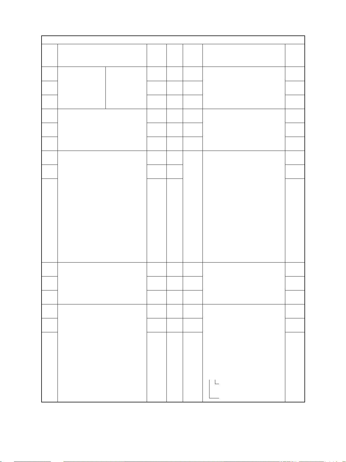
Code Name Mode Default
200
Date and time setting
201
Destination selection
202
Setting for externally installed copy counter
203
Line adjustment mode
204
Auto clear timer setting
205
Energy saver timer setting
206
Auto-power off timer
setting
220
Language displayed at
power ON
224
Paper size for bypass
feed
Paper size for upper cas-
225
sette
226
Paper size for lower cassette
227
Paper size for PFP upper cassette
228
Paper size for PFP lower
cassette
ALL – 13 digits
ALL 0:EUR 0~2
1:UC
2:JPN
ALL 0 0~3
ALL 0 0~1
ALL 3 0~10
ALL 11 0~15
ALL 9 0~20
ALL 0 0~4
ALL UNDEF 0~255
ALL JPN:A4 0~255
UC: LT
EUR:A4
ALL JPN:A3 0~255
UC: LD
EUR:A3
ALL JPN:A4-R 0~255
UC: LT-R
EUR:A4-R
ALL JPN:B4 0~255
UC: LG
EUR:A4
Setting mode (08)
Accept-
able
Value
Year / month / date / day / hour / minute / second
Example: 00 03 01 5 13 27 49
0:EUR 1:UC 2:JPN
0: External copy counter not used
1: Coin controller
2: Copy key card
3: Key copy counter
0: For factory shipment 1: For line
*Field: ‘0' must be selected
*Need to be checked when K-SRAM
was changed.
Timer to return the machine to the default
settings when the [START] key is not
pressed after the function and mode were
set.
0: Max. (150 sec.)
1 to 10: Set number X 15 sec.
Timer to automatically switch to the energy saving mode when the copier has
not been used.
0: Disabled 1: 30sec. 2: 60sec. 3: 90sec.
4: 120sec. 5: 150sec. 6: 3min. 7: 4min.
8: 5min. 9: 7min. 10: 10min. 11: 15min.
12: 20min. 13: 30min. 14: 45min. 15: 60min.
Timer to automatically turn OFF the power
when the copier has not been used.
0: 3min. 1: 5min. 2: 10min. 3: 15min.
4: 20min. 5: 25min. 6: 30min. 7. 40min
8. 50min. 9: 60min. 10: 70min. 11. 80min.
12. 90min. 13. 100min. 14. 110min.
15. 120min. 16. 150min 17. 180min.
18. 210min. 19. 240min. 20. Not used
0: Language1 1: Language2
2: Language3 3: Language4
4: Language5
Press the icon on the LCD to select the
size
Press the icon on the LCD to select the
size
Press the icon on the LCD to select the
size
Press the icon on the LCD to select the
size
Press the icon on the LCD to select the
size
Contents
Operation
procedure
group
1
1
1
1
1
1
1
1
1
1
1
1
1
December 2000 © TOSHIBA TEC 1 - 23
DP4500/3500 ERROR CODES AND SELF-DIAGNOSIS
Page 31

Code Name Mode Default
Paper size (A3)
229
feeding/widthwise direction
Paper size (A4-R)
230
feeding/widthwise direction
Paper size (A5-R)
231
feeding/widthwise direction
Paper size (B4)
232
feeding/widthwise direction
Paper size (B5-R)
233
feeding/widthwise direction
Paper size (LT-R)
234
feeding/widthwise direction
Paper size (LD)
235
feeding/widthwise direction
Paper size (LG)
236
feeding/widthwise direction
Paper size (ST-R)
237
feeding/widthwise direction
Paper size (COMPUTER)
238
feeding/widthwise direction
Paper size (FOLIO)
239
feeding/widthwise direction
Paper size (13 inch LG)
240
feeding/widthwise direction
Paper size (8.5X8.5inch)
241
feeding/widthwise direction
Paper size (Non-standard)
242
feeding/widthwise direction
Paper size (8K)
244
feeding/widthwise direction
Paper size (16K-R)
245
feeding/widthwise direction
Service call telephone
250
number
PM counter setting value
251
PM counter current value
252
Error history display
253
PFP/LCF installation
255
Paper size for LCF
256
ALL 420/297 182~432
ALL 297/210 182~432
ALL 210/148 182~432
ALL 364/257 182~432
ALL 257/182 182~432
ALL 279/216 182~432
ALL 432/279 182~432
ALL 356/216 182~432
ALL 216/140 182~432
ALL 356/257 182~432
ALL 330/210 182~432
ALL 330/216 182~432
ALL 216/216 182~432
ALL 432/279 148~432
ALL 390/270 182~432
ALL 270/195 182~432
ALL 0 14 digits
ALL
DP4500: 150000
DP3500: 116000
(0 for JPN)
ALL 0
ALL – –
ALL 0 0~4
ALL JPN:A4 0~255
UC: LT
EUR:A4
Setting mode (08)
Accept-
able
Value
/140~297
/140~297
/140~297
/140~297
/140~297
/140~297
/140~297
/140~297
/140~297
/140~297
/140~297
/140~297
/140~297
/105~297
/140~297
/140~297
Telephone numbers up to 14 digits can
be entered. Use the HELP/INFO key to enter a hyphen (-).
0~99999999
0~99999999
Displays the latest 8 error data.
0: Automatic
1: PFP single cassette type installed
2: PFP two cassette type installed
3: LCF installed
4: PFP/LCF not installed
Press the icon on the LCD to select the
size
Contents
Operation
procedure
group
3
3
3
3
3
3
3
3
3
3
3
3
3
3
3
3
1
1
1
2
1
1
DP4500/3500 ERROR CODES AND SELF-DIAGNOSIS
1 - 24 December 2000 © TOSHIBA TEC
Page 32

Code Name Mode Default
Copying total counter
257
value
MAX9 selection
300
Original counter display
302
Screen selection
331
A3/LD double count set-
352
ting
Upper cassette counter
356
Lower cassette counter
357
Bypass feed counter
358
LCF counter
359
PFP upper cassette
360
counter
Copy scan counter
361
Copy counter
362
Fax scan counter
363
Fax transmission coun-
364
ter
Fax reception counter
365
Fax/list counter
366
Printer counter
367
DSS scan counter
368
PFP lower cassette
370
counter
ADU counter
372
ADF counter
374
HDD error counter
390
HDD error counter
391
HDD error counter
392
ALL – 1~2
PPC 0 0~2
ALL 0 0 or 2
EUR : 2
ALL 0 0~1
ALL 1 0~1
ALL 0
ALL 0
ALL 0
ALL 0
ALL 0
ALL 0
ALL 0
ALL 0
ALL 0
ALL 0
ALL 0
ALL 0
ALL 0
ALL 0
ALL 0
ALL 0
PPC 0 0~32767
FAX 0 0~32767
LAN 0 0~32767
DSS
Setting mode (08)
Accept-
able
Value
1: > (Counter value displayed at left is
2: < (Counter value displayed at right is
0:999 1:99 2:9
0: Not displayed 2: Displayed
0: Copy 1: FAX
0: Single count 1: Double count
0~99999999
0~99999999
0~99999999
0~99999999
0~99999999
0~999999999
0~999999999
0~999999999
0~999999999
0~999999999
0~999999999
0~999999999
0~999999999
0~999999999
0~99999999
0~99999999
Counter for paper fed from the upper cassette
Counter for paper fed from the lower cassette
Counter for paper fed from the bypass tray
Counter for paper fed from LCF
Counter for paper fed from the PFP upper
cassette
Counts number of scannings in the copying mode.
Counts number of printings in the copying mode.
Counts number of scannings in the fax
transmission mode.
Counts number of documents transmitted
Counts number of polling documents received
Counts number of fax documents and lists/
reports (including group list) which are
output
Counts number of printings in the printer
mode
Counts number of scannings in the DSS
scanner mode
Counts paper fed from the PFP lower cassette
Counts number of automatic duplex copies
Counts papers fed from ADF
Reset by HDD formatting
Reset by HDD formatting
Reset by HDD formatting
Contents
overwritten on the counter value on the
right)
overwritten on the counter value on the
left)
( 1-32)
Operation
procedure
group
–
1
1
1
1
1
1
1
1
1
2
2
2
2
2
2
2
2
1
1
1
2
2
2
December 2000 © TOSHIBA TEC 1 - 25
DP4500/3500 ERROR CODES AND SELF-DIAGNOSIS
Page 33

Code Name Mode Default
Fuser roller thermistor
400
error counter
Drum life counter
401
(enter 0 to reset the counter)
Copier running time
402
counter
(enter 0 to reset the counter)
Fuser unit counter
403
(enter 0 to reset the counter)
Developer material
404
counter
(enter 0 to reset the counter)
Pre-running time before
408
1st print (thick paper)
Fuser roller temperature
410
during printing
Fuser roller temperature
411
during standby state
Fuser roller temperature
412
in energy saver mode
Fuser roller temperature
413
for thick paper
Correction of toner den-
414
sity adjustment value
Correction of toner sup-
455
ply amount
Setting for switchback
462
operation to copy mixedsized original on RADF
Speed switching of sub-
469
separation fan
ALL 0 0~19
ALL 0
ALL 0
ALL 0
ALL 0
ALL 0 0~15
ALL 12 0~14
ALL 12 0~12
ALL 0 0~1
ALL 2 0~4
ALL 0 0~8
ALL 0 0~2
ALL 0 0~1
ALL 0 0~1
Setting mode (08)
Accept-
able
Value
0: No error 1: C41 occurred once
2: C41 occurred continuously
3: Not used 4: Error C43 5: Error C44
6: Error C43 7: Error C44 8: Error C45
9: Error C44 10: Error C47 11: Error C47
12: Error C48 13: Error C49 14: Error C47
15: Error C48 16: Error C49 17: Error C47
18: Error C48 19: Error C49
0~99999999
0~99999999
0~99999999
0~99999999
Counts drum rotation time (sec.)
Counts the copier running time (min.)
Counts the fuser roller rotation time (sec.)
Counts the total consumed paper (Long
size: double count)
0: Not used 1: 1sec. 2: 2sec. 3: 3sec.
4: 4sec. 5: 5sec. 6: 6sec 7: 7 sec 8: 8sec.
9: 9sec. 10: 10sec. 11: 12 sec. 12: 14sec.
13: 16sec. 14: 18sec. 15: 20sec.
0: 140°C 1: 145°C 2: 150°C 3: 155°C
4: 160°C 5: 165°C 6: 170°C 7: 175°C
8: 180°C 9: 185°C 10: 190°C
11: 195°C 12: 200°C 13: 205°C
14: 210°C
0: 140°C 1: 145°C 2: 150°C 3: 155°C
4: 160°C 5: 165°C 6: 170°C 7: 175°C
8: 180°C 9: 185°C 10: 190°C 11: 195°C
12: 200°C
0: OFF 1: 100°C
0: Not used 1: 195°C 2: 200°C
3: 205°C 4: 210°C
Corrects the toner density adjustment
value set in 05-201.
0: 0 bit (No correction) 1: +3 bit 2: +6 bit
3: +9 bit 4: +12 bit 5: -3 bit 6: -6 bit
7: -9 bit 8: -12 bit
Corrects the rotation time of the toner motor during toner supply
0: 100% 1: 90% 2: 80%
0: Disabled 1: Enabled
0: High speed 1: Low speed
Contents
Operation
procedure
group
1
1
1
1
1
1
1
1
1
1
1
1
1
1
DP4500/3500 ERROR CODES AND SELF-DIAGNOSIS
1 - 26 December 2000 © TOSHIBA TEC
Page 34

Code Name Mode Default
Paper source priority
480
selection
Paper source automatic
481
alternation
Feeding retrying
482
Pre-running rotation of
483
polygonal motor
Auto-stop of pre-running
484
rotation of polygonal
motor
Rotation of polygonal
485
motor during the
standby state
Auto-stop timer for pre-
486
running rotation of polygonal motor
Polygonal motor rotation
489
number during the
standby state
Polygonal motor rotation
490
in the energy saver
mode
Separation charger life
497
counter (enter 0 to reset
the counter)
Density mode priority
503
selection at power on
Copy mode priority se-
550
lection
Screen setting for auto-
602
matic energy saver/automatic power off
Setting for automatic
603
duplexing mode
APS priority selection
604
ALL 0 0~5
ALL 1 0~2
ALL 0 0~1
ALL 0 0~2
ALL 0 0~1
ALL 0 0~1
ALL 0 0~2
ALL 5 0~5
ALL 0 0~1
ALL 0
PPC 0 0~1
PPC 0 0~2
ALL 1 0~1
EUR: 0
PPC 0 0~3
PPC 0 0~2
Setting mode (08)
Accept-
able
Value
0: A4/LT 1: LCF 2: Upper cassette
3: Lower cassette 4: PFP upper cassette
5: PFP lower cassette
Set if the cassette is automatically changed to the
other cassette which has the paper of the same size
when paper in the selected cassette has run out.
0: OFF
1: ON (Changed to the cassette which has the same
2: ON (Changed to the cassette which has the same
0: ON 1: OFF
0: ON (Motor starts rotating when original
1: OFF
2: ON (Motor starts rotating when original
0: Motor stops (according to the setting
1: Motor not stopped
0: Rotated (corresponding to the setting
1: Stopped
0: 15 sec. 1: 30sec. 2: 45sec.
This setting only effective when 08-484
is set to “0”
0: 38090.55[rpm] 1: 35000[rpm]
2: 30000[rpm] 3: 25000[rpm]
4: 20000[rpm] 5: 10000[rpm]
0: Stopped 1: 10000[rpm]
0~99999999
Counts the total number of consumed
paper (Long size: double count)
0: Automatic density 1: Manual density
0: Text/Photo 1: Photo 2: Text
0: Display OFF 1: Display ON
0: Disabled 1: Single-sided to duplex
2: Two-sided to duplex
3: User selection
0: APS 1: AMS 2: None
Operation
Contents
paper direction and size: ex. A4 to A4)
paper size. Paper with the different direction is acceptable as long as the size is the same: ex. A4 to
A4-R, L T-R to L T)
is placed on the RADF tray or original
glass.
is placed on the RADF tray.
vaue in 08-486)
value in 08-489)
procedure
group
1
1
1
1
1
1
1
1
1
1
1
1
1
1
1
December 2000 © TOSHIBA TEC 1 - 27
DP4500/3500 ERROR CODES AND SELF-DIAGNOSIS
Page 35

Code Name Mode Default
RADF priority mode se-
607
lection
BOOK duplex copy
611
Summer time mode
612
Paper size designation
613
for OTHER key
Original size priority
618
(same/mixed size)
Time lag before auto-
619
start of bypass feeding
Blank copying preven-
625
tion mode during RADF
jamming
Outer guide elimination
626
when paper size is not
selected for a bypass
feed printing
Rotation printing in the
627
non-sort mode for original fed from RADF
Direction priority of origi-
628
nal image
Department manage-
629
ment setting
PPC 0 0~1
PPC 0 0~1
ALL 0 0~1
PPC JPN:A5R 0~255
EUR:FOLIO
UC:COMP
PPC 0 0~1
ALL 4 0~10
PPC 0 0~1
PPC 1 0~1
PPC 0 0~1
PPC 0 0~2
PPC 7 0~7
Setting mode (08)
Accept-
able
Value
0:Continuous feed (original fed by press-
1: Single feed (original automatically fed
0: Left page to right page
2: Right page to left page
0: Not summer time 1: Summer time
Press the icon on the LCD to select the
size
0: Same sized original
1: Mixed sized original
Time to take to add paper and resume
paper feeding when paper in the bypass
tray has run out during the bypass feed
copying.
0: Paper is not dra wn in unless the START
1~10: Setting value x 0.5sec.
0: Disabled
1: Enabled (Printing is started after the
When a size is not selected for a bypass
feed printing,
0: OFF (Outer guide not eliminated (im-
1: ON (Image printed with a standard width
Set if the rotation printing is performed
when an original fed from the RADF needs
to be printed in the same direction with
the original placed on the original glass.
0: Not performed 1: Performed
0: Automatic 1: Portrait 2: Landscape
Contents
ing the START key)
by setting it on the tray)
key is pressed.
scanning is finished completely)
age printed in the largest size))
detected by the bypass guide.)
Value COPY FAX LAN/DSS
0X X X
1 XX
2X X
3 X
4X X
5 X
6X
7
---- Function enabled
X ----- Function disabled
Operation
procedure
group
1
1
2
1
1
1
1
1
1
1
1
Width setting for image
636
shift copying (linkage of
front side and back side)
DP4500/3500 ERROR CODES AND SELF-DIAGNOSIS
ALL 0 0~1
0: Enabled
1: Disabled
1 - 28 December 2000 © TOSHIBA TEC
1
Page 36

Code Name Mode Default
Counter display for
637
printer UI
Time display
639
Date display format
640
Automatic sorting mode
641
(RADF)
Sorter mode priority se-
642
lection
Reproduction ratio in
645
editing mode
Image position of 2-in-1
646
or 4-in-1
Returning finisher tray
648
when printing is finished
Magazine sort setting
649
2 in 1/4 in 1 setting
650
Annotation printing for-
651
mat setting
Cascade operation set-
652
ting
Cascade operation set-
653
ting
Direction priority for an-
657
notation printing
Auto-start setting for by-
658
pass feed printing
PPC 1 0~2
PPC 1 0~1
PPC JPN:0 0 ~2
UC:2
EUR:1
PPC 2 0~4
PPC 0 0~4
PPC 1 0 0~10
PPC 0 0~1
ALL 0 0~1
PPC 0 0~1
PPC 0 0~1
PPC 0 0~3
PPC 0 0~1
PRT 0 0~ 1
PPC 0 0~1
PRT 0 0~ 1
Setting mode (08)
Accept-
able
Value
0: Not displayed
1: Only total counter displayed
2: T otal counter , copy counter , f ax/list coun-
0: OFF 1: ON
0: 2000.11.28 1: 28.11.2000
2: 11.28.2000
0: Disabled 1: STAPLE 2: SORT
3: GROUP 4: ALTERNATION
0: NON SOR T 1: STAPLE 2: SORT
3: GROUP 4: ALTERNATION
Set the reproduction ratio for “X in 1” printing (including magazine sort) to “Reproduction ratio x adjustment reproduction
ratio”
0: 90% 1: 91% 2: 92% 3: 93%
4: 94% 5: 95% 6: 96% 7: 97%
8: 98% 9: 99% 10: 100%
0: Images placed at the upper left corner
1: Images placed in the center of each
Set whether the finisher tray is returned to
the 1-bin when printing is finished or not
0: Not returned 1: Returned
0: Left page to right page
1: Right page to left page
0: Horizontal 1: Vertical
0: OFF OFF
1: ON OFF
2: OFF ON
3: ON ON
Note: Hyphen printing format
ON: -1- OFF: 1
0: OFF 1: ON
0: OFF 1: ON
0: Short edge
1: Long edge
Set if the paper is automatically fed into
the copier when it is placed in the bypass
tray.
0: Auto-start OFF. Sheet is f ed by pressing
1: Auto-start ON
Contents
ter and printer counter displayed
of each page
page
Hyphen Dropout
(page number) (annotation/page number)
the [START] key.
Operation
procedure
group
1
1
1
1
1
1
1
1
1
1
1
1
1
1
1
December 2000 © TOSHIBA TEC 1 - 29
DP4500/3500 ERROR CODES AND SELF-DIAGNOSIS
Page 37

Code Name Mode Default
659
Auto-start setting for bypass feed printing
672
Initialization of department management information
690
HDD formatting
691
HDD type display
693
HDD standby mode
839
Control by humidity sensor
840
Toner density temperature control
855
Fuser roller temperature
during printing on OHP
Developer bias DC ad-
860
justment
861
Developer bias DC adjustment
862
Developer bias DC adjustment
PPC 1 0~1
–– –
ALL – 2
ALL – 0~2
ALL 242 0~255
ALL 0 0~3
ALL 1 0~1
ALL 7 0~7
PRT 128 0~255
PPC 128 0~255
(Text/
Photo)
PPC 128 0~255
(Text)
Setting mode (08)
Accept-
able
Value
Set if the paper is automatically fed into
the copier when it is placed in the bypass
tray.
0: Auto-start OFF. Sheet is f ed by pressing
1: Auto-start ON
Initializes the department managment information.
* Enter the code with the digital keys and
2: Normal format
0: Not formatted 1: Not used
2: Normal format
Timer for the HDD to enter the standby
mode.
* This value may need to be changed
0: Auto-toner control
1: Not used
2: Main charger grid, developer bias and
3:Auto-toner, main charger grid,
Set if the toner density is controlled by the
thermistor.
0: Controlled
1: Not controlled (Default)
0: 165°C 1: 170°C 2: 175°C 3: 180°C
4: 185°C 5: 190°C 6: 195°C 7: 200°C
Adjusts the developer transformer DC
output adjustment value in 05-205 (in PRT
mode)
Adjusts the developer transformer DC
output adjustment value in 05-205 (in PPC
Text/Photo mode)
Adjusts the developer transformer DC
output adjustment value in 05-205 (in PPC
text mode)
Contents
the [START] key.
press the [INITIALIZE] icon to perform the
initialization.
If the area storing the department
management information is destroyed for
some reason, “Enter Department code”
is displayed on the control panel even if
the department management function is
not set on. In this case, initialize the area
with this code. This area is normally initialized at the factory.
when the HDD is replaced since the
HDDs of the different manufactureres
have their own characteristics.
laser power control
developer bias and laser power control
Operation
procedure
group
1
–
1
2
1
1
1
1
1
1
DP4500/3500 ERROR CODES AND SELF-DIAGNOSIS
1 - 30 December 2000 © TOSHIBA TEC
Page 38

Code Name Mode Default
863
Developer bias DC adjustment
Main charger grid bias
864
adjustment
Main charger grid bias
865
adjustment
Main charger grid bias
866
adjustment
Main charger grid bias
867
adjustment
Laser power adjustment
872
Laser power adjustment
873
System firmware ROM
900
version
Printer ROM version
903
Scanner ROM version
905
RADF ROM version
907
Finisher ROM version
908
FROM main section soft-
920
ware version
FROM internal program
921
version
UI data fixed area ver-
922
sion
UI data common area
923
version
Version of UI data 1st
924
language in HDD
Version of UI data 2nd
925
language in HDD
Version of UI data 3rd
926
language in HDD
Version of UI data 4th
927
language in HDD
Version of UI data 5th
928
language in HDD
Version of UI data in
930
FROM displayed at
power ON
PPC 128 0~255
(Photo)
PRT 128 0~255
PPC 128 0~255
(Text/
Photo)
PPC 128 0~255
(Text)
PPC 128 0~255
(Photo)
PRT 128 0~255
PPC 128 0~255
ALL – –
ALL – –
ALL – –
ALL – –
ALL – –
ALL
ALL – –
ALL – –
ALL – –
ALL – –
ALL – –
ALL – –
ALL – –
ALL – –
ALL – –
Setting mode (08)
Accept-
able
Value
Adjusts the developer transformer DC
output adjustment value in 05-205 (in PPC
Photo mode)
Adjusts the main charger transformer output adjustment value in 05-210 (in PRT
mode)
Adjusts the main charger transformer output adjustment value in 05-210 (in PPC
Text/Photo mode)
Adjusts the main charger transformer output adjustment value in 05-210 (in PPC
Text mode)
Adjusts the main charger transformer output adjustment value in 05-210 (in PPC
Photo mode)
Adjusts the laser power adjustment value
in 05-286 (in PRT mode)
Adjusts the laser power adjustment value
in 05-286 (in PPC mode)
JPN: T320SJXXXX UC: T320SUXXXX
EUR: T320SEXXXX
Others: T320SXXXXX
320M-XXX
320S-XXX
DF-XXX
SDL-XXX
FIN-XXX
VX.X/X.X
VXXX.XXX
VXXX.XXX
VXXX.XXX
VXXX.XXX
VXXX.XXX
VXXX.XXX
VXXX.XXX
VXXX.XXX
VXXX.XXX
Contents
Operation
procedure
group
1
1
1
1
1
1
1
2
2
2
2
2
2
2
2
2
2
2
2
2
2
2
December 2000 © TOSHIBA TEC 1 - 31
DP4500/3500 ERROR CODES AND SELF-DIAGNOSIS
Page 39

<<Procedure to copy the total counter value (08-257)>>
1. Turn ON the power while [0] and [8] are pressed simultaneously .
2. Enter the code “257” with the digital ke ys and press the [START] key (the following is displa y ed).
Note: Before performing the following operations, note the current counter values.
3. Enter the value “1” or “2” with the digital ke y and press the [START] k ey.
The value entered is displayed on the left of the “%”, and the [SET] icon is displayed.
Note: The value can be erased by pressing the [C/S] k ey to change as long as the [START] k ey is not
pressed. (The value on the left of the “%” is reset to “0” by pressing the [C/S] k ey. )
• Enter “1” to copy the value of the total counter
(LGC board) (A) onto the value of the backup
counter (SLG board) (B).
• Enter “2” to copy the value of the backup coun-
ter (SLG board) (B) onto the value of the total
counter (LGC board) (A).
4. Press the [SET] icon to complete overwriting of
the counter value.
(A) (B)
(A) (B)
Note: The screen returns to the code entry screen
without copying (overwriting) the value when
the [CANCEL] icon is pressed.
DP4500/3500 ERROR CODES AND SELF-DIAGNOSIS
1 - 32 December 2000 © TOSHIBA TEC
Page 40

2. ADJUSTMENT
2.1 Formatting the Hard Disk
<Procedure>
(1 ) Turn ON the power while the digital ke ys [0] and [8] are pressed simultaneously.
(2 ) Confirm that “Test Mode” is display ed on the control panel. Enter the code “690” and press the [START]
key. The display changes to “System Mode”.
(3) Enter “2” and then press the [SET] icon or [INTERRUPT] k e y.
(4) “Wait” is displayed.
(5 ) T urn OFF the power after the message “Wait” is gone.
December 2000 © TOSHIBA TEC 2 - 1 DP4500/3500 ADJUSTMENT
Page 41

2.2 Adjustment of Auto-Toner Sensor
Note: Check if the cleaning blade is pressed against the drum before performing this adjustment.
<Procedure> (Code “200” in the adjustment mode (05))
(1 ) Install the cleaner and developer unit in the copier (the cleaning blade is in contact with the drum).
(2 ) T urn ON the power while the digital ke ys “0” and “5” are pressed simultaneously.
The following is displayed on the control panel.
100%
[0][5]
[POWER]
(3) Enter “200” using the digital keys and press the [START] key.
The display changes as follows.
[200] [START]
Note: A : indicates the controlled value of the auto-toner sensor output. Press the Up or Down
icon to change the value.
B : indicates the output voltage of the auto-toner sensor (2.30 V in the abov e case).
The drum, developer unit, etc. are in operation.
C : indicates the latest adjustment value.
(4) After about two minutes, the value B automatically starts changing.
TEST MODE
B
230%
TEST MODE
128
C
A
200
A3
A3
128
A
230%
TEST MODE WAIT
128
(5) After a short time, the value B becomes stable and the display changes as follows.
B
240%
ADJUSTMENT MODE
128
(6) Check if the value B is within the range of 235 to 245 (the output voltage range of the auto-toner
sensor is 2.35 V to 2.45 V).
DP4500/3500 ADJUSTMENT 2 - 2 December 2000 © TOSHIBA TEC
200
200
A3
128
A3
150
A
Page 42

(7) If the value B is not within the range of 235 to 245%, press the Up or Down icon to adjust the value
manually.
Note: The relation between the icons and the values A and B is as follows.
Icon to be pressed Value A Value B
Up Increased Increased
Down Decreased Decreased
(8) Press the [SET] icon or [INTERRUPT] key.
The drum, developer unit, etc. are stopped and the following is displayed.
[SET]
or
[INTERRUPT]
100%
TEST MODE READY
A
A3
[0] [9]
100%
1
A4
December 2000 © TOSHIBA TEC 2 - 3 DP4500/3500 ADJUSTMENT
Page 43

2.3 Dimensional Adjustment of Copied Image
2.3.1 Overview
The followings are the items in the copy image dimensional adjustment mode.
The adjustment must be performed in the following order.
Items to adjust Code
(1) Paper alignment (450) (452) (448) (449)
(455) (457) (458)
a) Reproduction ratio of primary scanning direction
(Fine adjustment of polygonal motor rotation speed) (401)
b) Image position of primary scanning direction
(Laser writing start position) (411) (410)
c) Reproduction ratio of secondary scanning direction
(Fine adjustment of main motor rotation speed) (421)
d) Image position of secondary scanning direction
(Laser writing start position) (441) (440) (443) (444) (445) (442)
(2) Printer related adjustmet(3) Scanner related adjustment
e) Image position of primary scanning direction during
duplex copying (Laser writing start position) (498)
a) Image distortion –
b) Reproduction ratio of primary scanning direction
(Fine adjustment of polygonal motor rotation speed/PPC) (405)
c) Image position of primary scanning direction
(Deviation correction of the scanner primary scanning
start position) (306)
d) Reproduction ratio of secondary scanning direction (340)
e) Image position of secondary scanning direction
(Deviation correction of the scanner secondary
scanning start position) (305)
f) Top margin (430)
g) Right margin (432)
h) Bottom margin (433)
DP4500/3500 ADJUSTMENT 2 - 4 December 2000 © TOSHIBA TEC
Page 44

[Procedure to input the adjustment values]
In accordance with the following procedure, adjust each adjustment item so that the measured
values obtained from the test copy satisfy the specification. Single-side test copying can be performed (in the normal copy modes) by pressing the [F AX] k ey immediately after entering the adjustment mode (05).
<Keys used in operation> <Display>
100%
[0] [5]
[POWER]
1
[Digital keys]: Enter a code.
[START]
[Digital keys]:Enter an adjust-
ment value.
[C/S] Corrects the value
[SET]
or
[INTERRUPT]
[FAX]: Test copy
V alue “ZZZ” is newly
stored in BC-RAM
instead of “YYY”.
TEST MODE
100%
TEST MODE
Current adjustment value
100%
TEST MODE
100%
WAIT WARMING UP
A
XXX
ZZZYYY
A
A
Varies depending on the code “xxx”
entered with the digital keys.
A3
Code No.
A3
Adjustment value
newly entered (YYY
is default display).
A3
A3
If the copied image does
not satisfy the specifications, return to y, and
perform the adjustment
again.
[0] [9]:To exit the adjustment
mode
December 2000 © TOSHIBA TEC 2 - 5 DP4500/3500 ADJUSTMENT
100%
COPYING
A
A3
Page 45

2.3.2 Paper alignment
<Procedure> (The adjustment code for each cassette is as follows.)
Copier
Upper Lower
cassette cassette
(450) (452)
(1)
[POWER]
Current value
[0] [5]
u
displayed
u
Enter new
u
PFP
Upper Lower
cassette cassette
(448) (449)
In case of adjustment for papers in the copier
cassette, PFP, ADU and bypass tray
[STA RT](Code) (Sub-code) [START]
value
(Stores value in the RAM)
u
[SET]
u
or
[INTERRUPT]
(2 ) Check if image void is occurring. If there is any,
reduce the value as in “31” n “30” n “29”… until
the void disappears. At this time, make sure there
are no paper jams.
Increasing the aligning amount may increase
the scraping noise caused by the paper and the
Mylar as the paper is transported by the registration roller .
Decrease the value if the noise is annoying.
(3) P erf orm the same procedure for the ADU , LCF
and bypass feeding.
ADU
(455)
u
[Cassette selection] [FAX]
V oid
LCF
(457)
u
u
(Test print)
50~100mm
Bypass
feed
(458)
u
u
[0] [9]
(Exit)
Note: When paper thinner than that specified is used, paper jams may occur frequently at the registra-
tion section. In this case, it is advised to change (reduce) the aligning amount. However, if the
aligning amount is reduced too much, this may cause the shift of the leading edge position.
Select the appropriate value when the adjustment value is changed while confirming if the leading edge is not shifted.
* As a tentative countermeasure, the service life of the feed roller can be extended by increasing the
aligning amount.
DP4500/3500 ADJUSTMENT 2 - 6 December 2000 © TOSHIBA TEC
Page 46

2.3.3 Printer related adjustment
(a) Reproduction ratio adjustment of the primary scanning direction (fine adjustment of polygonal motor
rotation speed/PRT)
1. T urn ON the power while the digital k eys [0] and [5] are pressed simultaneously. n(Adjustment mode)
2. Press [1] and [FAX]. (A grid pattern of 10 mm squares is printed out: Use A3 (LD) in the lower cassette .)
3. Measure the distance A from the first grid line to the 21st of the grid pattern.
4. Check if the distance A is within 200 ± 0.5 mm or not.
5. If not, change the value taking the following procedure, and measure the distance A again.
<Procedure> (Adjustment mode)n(Enter the code [401] with the digital k eys)n[START]
n(Enter a value (acceptable values: 0 to 255) with the digital keys)
nPress the [SET] icon or the [INTERRUPT] key to store the value in the RAM
n“100% A” is displa yed.nPress [1]n[FAX]n(A grid pattern is printed out)
*The larger the adjustment value, the longer the distance A becomes
(approx. 0.5 mm/4 steps).
(b) Image position adjustment of the primary scaning direction (the adjustment of the laser writing start
position)
1. Turn ON the power while the digital ke ys [0] and [5] are pressed simultaneously . n(Adjustment mode)
2. Press [1]n[F AX] (A grid pattern is printed out: Use A3 (LD) in the lo wer cassette.)
3. Measure the distance B from the leading edge of the paper to the 6th line of the grid pattern.
4. Check if the distance B is in the range of 52 ± 0.5 mm.
5. If not, change the value taking the following procedure and measure the distance B again.
<Procedure> (Adjustment mode)n(Enter the code [411] with the digital k eys)nPress [START]
n(Enter a value (acceptable values: 0 to 255) with the digital keys)
nPress the [SET] icon or the [INTERRUPT] key to store the value in the RAM.
n“100% A” is displayed.
nPress [1]n[FAX]n(A grid pattern is printed out.)
*The larger the adjustment value, the longer the distance B becomes
(approx. 0.5 mm/10 steps).
6. After the adjustment for the code 411 is completed, apply the same adjustment value for the code 410.
<Procedure> (Adjustment mode)n(Enter the code [410] with the digital k eys)nPress [START]
n(Enter the same value entered in the step 5 above with the digital keys)
nPress the [SET] icon or the [INTERRUPT] key to store the value in the RAM.
Note: The first line of the grid pattern is occasionally not printed out.
December 2000 © TOSHIBA TEC 2 - 7 DP4500/3500 ADJUSTMENT
Page 47

(c) Reproduction ratio adjustment of the secondary scanning direction (fine adjustment of main motor
rotation speed)
1. Turn ON the power while the digital ke ys [0] and [5] are pressed simultaneously . n(Adjustment mode)
2. Press [1] and then [F AX]. (A grid pattern is printed out. Use A3 (LD) in the low er cassette.)
3. Measure the distance C from the 1st line at the trailing edge of the paper to the 21st line of the grid
pattern.
4. Check if the distance C is within the range of 200 ± 0.5 mm.
5. If not, change the value taking the following procedure and measure the distance C again.
<Procedure> (Adjustment mode)n(Enter the code [421] with the digital k eys)n[START]
n(Enter a value (acceptable values: 0 to 255) with the digital keys)
nPress the [SET] icon or the [INTERRUPT] key to store the value in the RAM.
n“100% A” is displa yed.nPress [1]n[FAX]n(A grid pattern is printed out)
*The larger the adjustment value, the longer the distance C becomes (0.5 mm/4 steps).
(d) Image position adjustment of the secondary scanning direction (the adjustment of the laser writing
start position)
This adjustment has to be performed for each paper source.
The following table shows the order of the paper source to be adjusted, code, paper size and acceptable
values.
Order for
adjustment size value
1 Lower cassette 441 A3 0 to 40
2 Upper cassette 440 A4 0 to 15
3 LCF 443 A4 0 to 15
4 PFP 444 A3 0 to 15
5 ADU 4 4 5 A 3 0 to 15 Paper fed from the lower cassette
6 Bypass feed 44 2 A 4 0 to 15
Paper source Code
Paper Acceptable
Remarks
1. Turn ON the power while the digital ke ys [0] and [5] are pressed simultaneously . n(Adjustment mode)
2. Press [1] ([3] for ADU)n[FAX]. (A grid pattern is printed out.)
3. Measure the distance D from the leading edge of the paper to the 5th line of the grid pattern.
4. Check if the distance D is within the range of 52 ± 0.5 mm.
5. If not, change the value taking the following procedure and measure the distance D again.
<Procedure> (Adjustment mode)n(Enter the code [see tab le abov e] with the digital ke ys)n[START]
n(Enter a value (the acceptable values: see the table above) with the digital keys)
nPress the [SET] icon or the [INTERRUPT] key to store the value in the RAM.
n“100% A” is displa yednPress [1] ([3] for ADU)n[FAX]n(A grid pattern is printed out)
*The larger the adjustment value, the shorter the distance D becomes (0.4 mm/steps).
DP4500/3500 ADJUSTMENT 2 - 8 December 2000 © TOSHIBA TEC
Page 48

(e ) Image position adjustment of the primary scanning direction during duplex printing (the adjustment of
the laser writing start position)
(e-1) Adjustment for long-sized paper
1. Turn ON the power while the digital ke ys [0] and [5] are pressed simultaneously . n(Adjustment mode)
2. Press [3]n[FAX] (A grid pattern is printed out on both sides of the paper: Use A3 (LD) in the lower
cassette.)
3. Check the grid pattern on the back side of the paper. Measure the distance E from the leading edge of
the paper to the 6th line of the grid pattern.
4. Check if the distance E is in the range of 52 ± 0.5 mm.
5. If not, change the value taking the following procedure and measure the distance E again.
<Procedure> (Adjustment mode)n(Enter the code [498] with the digital k eys)nPress [0]n[START]
n(Enter a value (acceptable values: 0 to 255) with the digital keys)
nPress the [SET] icon or the [INTERRUPT] key to store the value in the RAM.
n“100% A” is displayed.
nPress [3]n[FAX]n(Grid patterns are printed out on both sides of the paper)
*The larger the adjustment value, the longer the distance E becomes
(approx. 0.5 mm/10 steps).
(e-2) Adjustment for short-sized paper
After the adjustment for long-sized paper is completed, apply the same adjustment v alue f or short-sized
paper.
<Procedure> (Adjustment mode)n(Enter the code [498] with the digital k eys)nPress [1]n[START]
n(Enter the same value entered for long-sized paper with the digital keys)
nPress the [SET] icon or the [INTERRUPT] key to store the value in the RAM.
Note: The first line of the grid pattern is occasionally not printed out.
December 2000 © TOSHIBA TEC 2 - 9 DP4500/3500 ADJUSTMENT
Page 49

Feeding direction
1
21
A
6
B, E
D
5
C
121
[Grid pattern]
<Order of distances to be adjusted>
[0] [5] [POWER] n [1] ([3] for duplex copying) n [FAX]
A: 05-401 (lower cassette, A3/LD) n 200±0.5 mm (+0.5 mm/4 steps)
B: 05-411 (lower cassette, A3/LD) n 52±0.5 mm (+0.5 mm/10 steps) n enter the same value for 05-410.
C: 05-421 (lower cassette, A3/LD) n 200±0.5 mm (+0.5 mm/4 steps)
D: 05-441 (lower cassette, A3/LD), 440 (upper cassette, A4/LT), 443 (LCF, A4/L T), 444 (PFP, A3/LD), 445
(ADU, A3/LD), 442 (bypass feed, A4/LT) n 52±0.5 mm (–0.4 mm/steps)
E: 05-498-0, 498-1 n 52±0.5 mm (+0.5 mm/10 steps)
DP4500/3500 ADJUSTMENT 2 - 10 December 2000 © TOSHIBA TEC
Page 50

2.3.4 Scanner related adjustment
(a) Image distortion adjustment
Feeding direction
Step 1
Step 2
A
C
1. T urn ON the power while the digital k eys [0] and
[5] are pressed simultaneously.
2. Press [F AX] to make a copy of any image on a
sheet of A3 (LD) paper.
B
Feeding direction
D
Adjustment screw for the mirror-1
3. Enter [308] and press the [START] key to mov e
the carriage to the position for adjustment (exit
side).
4. Make an adjustment in the order of step 1 and
2.
[Step 1]
In the case of A: Tighten the adjustment screw
for mirror-2 (CW).
In the case of B: Loosen the adjustment screw
for mirror-2 (CCW).
[Step 2]
In the case of C: Tighten the adjustment screw
for mirror-1 (CW).
In the case of D: Loosen the adjustment screw
for mirror-1 (CCW).
Adjustment screw for the mirror-2
December 2000 © TOSHIBA TEC 2 - 11 DP4500/3500 ADJUSTMENT
Page 51

(b) Reproduction ratio adjustment of the primary scanning direction (fine adjustment of the polygonal
motor rotation speed/PPC)
1. T urn ON the power while the digital k eys [0] and [5] are pressed simultaneously. n (Adjustment mode)
2. Place a ruler on the original glass (along the direction from the rear to the front of the machine).
3. Press the [F AX] key and make a copy in the condition of A3 (LD), 100% and lower cassette.
4. Measure the distance A from 10 mm to 270 mm of the copied image of the ruler.
5. Check if the distance A is within the range of 260±0.5 mm.
6. If not, change the value taking the following procedure, and repeat the steps 3 to 5 until the distance
falls within range.
<Procedure> (Adjustment mode) n (Enter the code [405] with the digital k eys) n [START]
n (Enter a value (acceptable values : 0 to 255) with the digital keys)
n Press the [SET] icon or the [INTERRUPT] key to store the value in the RAM.
n (“100% A” is displayed.)
* The larger the adjustment v alue , the higher the reproduction ratio and the longer the
distance A become (approx. 0.5 mm/4 steps).
Copied image of the ruler
A
50 100 150 200 250
Feeding direction
DP4500/3500 ADJUSTMENT 2 - 12 December 2000 © TOSHIBA TEC
Page 52

(c) Image position adjustment of the primary scanning direction (Deviation adjustment of the scanner
primary scanning start position)
1. T urn ON the power while the digital k eys [0] and [5] are pressed simultaneously. n (Adjustment mode)
2. Place a ruler on the original glass with its leading edge pushed against the rear side and its side along
the original scale on the left.
3. Press the [F AX] key and make a copy in the condition of A3 (LD), 100% and lower cassette.
4. Measure the distance B from the left edge of the paper to 10 mm of the copied image of the ruler.
5. Check if the distance B is within the range of 10±0.5 mm .
6. If not, change the value taking the following procedure, and repeat the steps 3 to 5 until the distance
falls within range.
<Procedure> (Adjustment mode) n (Enter the code [306] with the digital k eys) n [START]
n (Enter a value (acceptable values : 0 to 255) with the digital keys)
n Press the [SET] icon or the [INTERRUPT] key to store the value in the RAM.
n (“100% A” is displayed.)
* The larger the adjustment value, the more the image is shifted to the left and the
distance B becomes narrower (0.0423 mm/step).
Copied image of the ruler
50 100 150 200
Feeding direction
December 2000 © TOSHIBA TEC 2 - 13 DP4500/3500 ADJUSTMENT
B
Page 53

(d ) Reproduction ratio adjustment of the secondary scanning direction
1. T urn ON the power while the digital k eys [0] and [5] are pressed simultaneously. n (Adjustment mode)
2. Place a ruler on the original glass with its leading edge pushed against the original scale on the left.
3. Press the [F AX] key and make a copy in the condition of A3 (LD), 100% and lower cassette.
4. Measure the distance C from 210 mm to 410 mm (in case of A3) or from 220 mm to 420 mm (in case
of LD) of the copied image of the ruler.
5. Check if the distance C is within the range of 200±0.5 mm.
6. If not, change the value taking the following procedure, and repeat steps 3 to 5 until the distance falls
within range.
<Procedure> (Adjustment mode) n (Enter the code [340] with the digital k eys) n [START]
n (Enter a value (acceptable values : 0 to 255) with the digital keys)
n Press the [SET] icon or the [INTERRUPT] k e y to store the value in the RAM.
n (“100% A” is displayed.)
* The larger the adjustment value, the lower the reproduction ratio becomes. (0.05
mm/step)
Copied image of the ruler
200 250 300 350 400
200 250 300 350 400
Feeding direction
C (LD)
C (A3)
DP4500/3500 ADJUSTMENT 2 - 14 December 2000 © TOSHIBA TEC
Page 54

(e ) Image position adjustment of the secondary scanning direction (Deviation adjustment of the scanner
secondary scanning start position)
1. T urn ON the power while the digital k eys [0] and [5] are pressed simultaneously. n (Adjustment mode)
2. Place a ruler on the original glass with its leading edge pushed against the original scale on the left.
3. Enter “305” with the digital keys and press the [START] key n [SET] icon or [INTERRUPT] key n
[FAX] key to make a copy in the condition of A3(LD), 400% and lower cassette .
4. Measure the distance D from the leading edge of the paper to 10 mm of the copied image of the ruler.
5. Check if the distance D is within the range of 34±0.5 mm.
6. If not, change the value taking the following procedure, and repeat the steps 3 to 5 until the distance
falls within range.
<Procedure> (Adjustment mode) n (Enter the code [305] with the digital k eys) n [START]
n (Enter a value (acceptable values : 0 to 255) with the digital keys)
n Press the [SET] icon or the [INTERRUPT] key to store the value in the RAM.
n (“100% A” is displayed.)
* The larger the adjustment value, the more the image is shifted to the leading edge (0.68
mm/step).
Copied image of the ruler
10 20 30 40
D
Feeding direction
December 2000 © TOSHIBA TEC 2 - 15 DP4500/3500 ADJUSTMENT
Page 55

(f) T op margin
1. T urn ON the power while the digital k eys [0] and [5] are pressed simultaneously. n (Adjustment mode)
2. Open the platen cover or ADF.
3. Press the [F AX] key and make a copy in the condition of A3 (LD), 100% and lower cassette.
4. Measure the blank area E at the leading edge of the copied image.
5. Check if the blank area E is within the range of 3±0.5 mm.
6. If not, change the value taking the following procedure, and repeat the steps 3 to 5 until the distance
falls within range.
<Procedure> (Adjustment mode) n (Enter the code [430] with the digital k eys) n [START]
n (Enter a value (acceptable values : 0 to 255) with the digital keys)
n Press the [SET] icon or the [INTERRUPT] key to store the value in the RAM.
n (“100% A” is displayed.)
* The larger the adjustment value, the wider the blank area becomes (0.0423 mm/step).
Feeding direction
E
(g ) Right margin
1. T urn ON the power while the digital k eys [0] and [5] are pressed simultaneously. n (Adjustment mode)
2. Open the platen cover or ADF.
3. Press the [F AX] key and make a copy in the condition of A3 (LD), 100% and lower cassette.
4. Measure the blank area F at the right side of the copied image.
5. Check if the blank area F is within the range of 2±0.5 mm.
6. If not, change the value taking the following procedure, and repeat the steps 3 to 5 until the area falls
within range.
<Procedure> (Adjustment mode) n (Enter the code [432] with the digital k eys) n [START]
n (Enter a value (acceptable values : 0 to 255) with the digital keys)
n Press the [SET] icon or the [INTERRUPT] key to store the value in the RAM.
n (“100% A” is displayed.)
* The larger the adjustment value, the wider the blank area at the right side becomes
(0.0423 mm/step).
Feeding direction
F
DP4500/3500 ADJUSTMENT 2 - 16 December 2000 © TOSHIBA TEC
Page 56

(h ) Bottom margin
1. T urn ON the power while the digital k eys [0] and [5] are pressed simultaneously. n (Adjustment mode)
2. Open the platen cover or ADF.
3. Press the [F AX] key and make a copy in the condition of A3 (LD), 100% and lower cassette.
4. Measure the blank area G at the trailing edge of the copied image.
5. Check if the blank area G is within the range of 2±0.5 mm.
6. If not, change the value taking the following procedure, and repeat the steps 2 to 4 until the area falls
within range.
<Procedure> (Adjustment mode) n (Enter the code [433] with the digital k eys) n [START]
n (Enter value (acceptable values : 0 to 255) with the digital keys)
n Press the [SET] icon or the [INTERRUPT] key to store the value in the RAM.
n (“100% A” is displayed.)
* The larger the adjustment value, the wider the blank area at the trailing edge be-
comes (0.0423 mm/step).
Feeding direction
G
December 2000 © TOSHIBA TEC 2 - 17 DP4500/3500 ADJUSTMENT
Page 57

2.4 Image Quality Adjustment
2.4.1 Image density
Perform the image density adjustment in the adjustment mode “05” if the user requests to change the
image density.
Copy mode
T ext/Photo
50 3 501 5 04 Manual density center value The larger the value, the darker the image becomes
Code
Adjust the image density to satisfy the user’s request b y taking the follo wing procedure while studying the
image obtained from the test copy and the currently entered values.
<Keys used in the oper ation> <Display>
505 506 507
508 509 510
51 4 5 12 51 5 Automatic density
1
[Digital keys]: Enter the code.
Photo Text
[0] [5]
[POWER]
[START]
Items to adjust Remarks
Manual density light step value
Manual density dark step value
100%
TEST MODE
100%
TEST MODE
The larger the value, the lighter the image of the lighter steps become
The larger the value, the darker the image of the darker steps become
The larger the value, the darker the image becomes
Varies depending on the code “xxx”
entered with the digital keys.
A
Code No.
XXX
A3
A3
[Digital keys]:Enter the adjust-
ment value.
[C/S] Corrects the values
[SET]
:
V alue “ZZZ” is ne wly stored in
BC-RAM instead of “YYY”.
or
[INTERRUPT]
[F AX]: Test copy
Return to y to make
the adjustment again
[0] [9]: To exit the adjustment
mode
ZZZYYY
Current adjustment value
100%
TEST MODE
100%
WAIT W ARMING UP
100%
COPYING
Notes) 1. Only one single-sided copy can be made.
2. Since the duplex copying is disabled, make a test copy
after exiting the adjustment mode.
A
A
A
A3
A3
A3
Newly entered
adjustment value
(YYY is the default
display).
DP4500/3500 ADJUSTMENT 2 - 18 December 2000 © TOSHIBA TEC
Page 58

2.4.2 Sharpness (HPF) adjustment
If user requests to make the image sharpness softer or harder, adjust the sharpness setting (HPF intensity) in the adjustment mode “05”.
Code
Copy mode
T e xt/Photo
62 0 62 1 622 Sharpness setting
Photo T ext
Items to adjust Remarks
Enter one of the following values in the copy mode.
(HPF intensity)
Units: 1: Text/Photo 2: Photo 5: Text
Tens: 0: Use default value
1~9: Change intensity
(The larger the value, the sharper the
image becomes.)
• Example of value entry in case the copy
mode is “Text/Photo”.
2 1
Fixed value for Text/Photo mode
Enter a value 0 to 9
The entry procedure of the adjustment value is the same as that for “2.4.1 Image density”.
2.4.3 Gamma slope adjustment
If the user requests to change the gamma slope, perform the gamma slope adjustment in the adjustment
mode “05”.
Code
Copy mode
T ext/Photo
593 5 94 5 95 Gamma slope adjustment 0: Use default value (equivalent to the
Photo T ext
Items to adjust Remarks
set value 5)
1 to 9: Gamma data (The larger the value,
the darker the image becomes)
The entry procedure of the adjustment value is the same as that for “2.4.1 Image density”.
December 2000 © TOSHIBA TEC 2 - 19 DP4500/3500 ADJUSTMENT
Page 59

2.4.4 Setting for the range correction
The range correction on the values of the background peak/text peak can be set in the adjustment mode
(05).
If they are fixed, the range correction is performed with standard values.
The values of the background peak and text peak affect the reproduction of the background density and
text density respectively.
Code
Copy mode
Text/Photo
570 5 71 57 2 Range correction
693 6 94 69 5 Range correction
Photo Text
Items to set Remarks
for original
manually set on the
original glass
for original set on
the RADF
The following are the default values set for each copy
mode.
Text/Photo: 12, Photo: 12, Text: 44
Units: Setting for the automatic density mode
Tens: Setting for the manual density mode
1: Value of the background peak - fixed
Value of the text peak - fixed
2: Value of the background peak
- varies depending on image data to be copied.
Value of the text peak - fixed
3: Value of the background peak - fixed
Value of the text peak
- varies depending on image data to be copied.
4: Value of the background peak
- varies depending on image data to be copied.
Value of the text peak
- varies depending on image data to be copied.
The entry procedure of the adjustment value is the same as that for “2.4.1 Image density”.
DP4500/3500 ADJUSTMENT 2 - 20 December 2000 © TOSHIBA TEC
Page 60

2.5 High-Voltag e Adjustment
(1) Preparation
Developer Bias Main Charger Transfer Charger Separation Charger
Developer unit
Cleaner unit
Developer unit
connector of the copier
(+) terminal
(–) terminal
Digital Tester
Function switch
Full-scale
Remarks
How to turn on the power
Remarks
Disconnect the connector.
Remove the drum and
install the cleaner unit in
the copier.
Not connected
Connect in the hole at the
front side of the developer
unit.
Connect to the machine
frame (to ground).
Use a digital tester with an input resistance of 10 M (RMS value) or higher.
Attach the door switch jig and press the front cover opening/closing switch while the front cover is open.
Refer to (b) Connection Refer to (c) Connection Refer to (d) Connection for
for developer bias for main charger transfer/separation charger adjustment.
adjustment. adjustment.
Remove from the copier. (Not used)
Install the unit together with the current measuring jig in the copier.
NOTE 1:Connect the green cable of the current measuring jig to ground on the
copier frame. Refer to (a) Installation of current measuring jig.
Connect the jig detection conector with the developer unit connector of the
copier.
Connect to the main
charger case (between the
case and the terminal).
Connect with the white cable of the current measuring jig (to ground).
DC
1,000 V
Connect with the red cable of the current
measuring jig.
AC
2V
(a ) Installation of the current measuring jig
Notes: 1.Clean the toner recovery auger when the
toner is sticking to it. Then attach the jig.
2.Do not damage the tip of the separation
fingers.
3.Remove the cleaner stay before installing
the jig.
1. Unlock the cleaning blade using the blade
releasing jig. ( Chapter 11.5 [C] in the Service Manual)
2. Insert the shaft through the hole at the front side of the cleaner.
3. Put the shaft through the current measuring jig and put it into the rear hole to fix it to the cleaner. Attach
the cleaner stay.
4. Install the cleaner unit in the copier with 2 screws, and connect the jig detection connector with the
connector of the dev eloper unit in the copier .
Fix the green cable of the current measuring jig to the machine frame.
Notes: 1. Set the current measuring jig in the center of the cleaner unit.
2. High-voltage adjustment cannot be performed without connecting the jig detection connector
(except the developer bias adjustment).
December 2000 © TOSHIBA TEC 2 - 21 DP4500/3500 ADJUSTMENT
Page 61

(b ) Connection for developer bias adjustment
Front cover
opening/closing switch
(–) terminal
Connected to the machine frame
(c) Connection for main charger adjustment
Front cover
opening/closing switch
(+) terminal
Connect the jig detection connector
with the developer unit connector
(+) terminal
(d ) Connection for transfer/separation charger adjustment
Front cover
opening/closing switch
Connect the jig detection
connector with the developer
unit connector
Grounded to the machine
frame (green cable)
(–) terminal
(Connect the white cable of the jig)
Grounded to the machine
frame (green cable)
(–) terminal
(Connect the white cable of the jig)
(+) terminal
(Connect the red cable of the jig)
DP4500/3500 ADJUSTMENT 2 - 22 December 2000 © TOSHIBA TEC
Page 62

(2) Operation
NOTES
1. After the drum is replaced with a new one, reset the drum life counter to “0” (08-401).
2. After the developer material is replaced with a new one, reset the developer material life counter to
“0” (08-404).
3. After the separation charger wire is replaced with a new one, reset the separation charger life
counter to “0” (08-497).
4. A current measuring jig is necessary to adjust the high-voltage output (except the developer bias
adjustment).
5. If the connectors of the current measuring jig and the developer unit of the copier are not connected
with each other, high-voltage adjustment codes except those for the developer bias are not accepted. Do not connect anything with the connector of the developer unit of the copier during the
measurement of the developer bias.
6. After the high-voltage transformer is replaced with a new one, the output of the main charger,
developer bias charger , transf er charger and separation charger need to be checked and adjusted.
Connect the digital testers as described in (1) Preparation, and follow the procedure on the next page to
adjust the output from the main charger, de veloper bias charger , transf er charger and separation charger .
December 2000 © TOSHIBA TEC 2 - 23 DP4500/3500 ADJUSTMENT
Page 63

<Keys to press> <Display>
[0][5]
[POWER]
y
[Digital keys]: Enter the code.
[ST AR T]
[UP] or [DOWN]
[SET] icon
or
[INTERRUPT]
: Adjust the value “YYY” to satisfy the following table.
Code 210 205 221
Adjustment value –790 ±5V –521 ±5V 413 ±45mV
Code 231
Adjustment RMS value 1267 ±115mV
Value Mean value 1235 ±112mV
: Adjusted value “YYY” is stored in the BC-RAM.
100%
TEST MODE
100%
TEST MODE
YYY
Current set value
Main Developer
charger
Separation
Center value
100%
TEST MODE
A
XXX
bias charger
A
A3
A3
Transfer charger
Center value
A3
Code No.
Return to y to enter
the other adjustment
mode.
[0][9] : To exit the adjustment mode.
Note: The “adjustment value” indicates the output voltage of the D/A converter (IC47 and IC48) on the logic PC
board. The relation between the output voltage and adjustment value is as follows:
Output voltage = (Adjustment value + 1)
256 ✕ 5 V
DP4500/3500 ADJUSTMENT 2 - 24 December 2000 © TOSHIBA TEC
Page 64

(3 ) Precautions
(a) Developer bias
Note for adjustment
Adjust the developer bias if fogging occurs over the entire image even though the main charger grid
voltage and toner density are appropriate. However, the following may occur if the developer bias is
lowered too much:
• Image contrast becomes low.
• Image is patchy or blurred.
• The carrier in the developer material adheres to the photoconductive drum, causing scratches around
the cleaner.
(b) Transfer
Items to check before adjustment
Blotched image or poor transfer can be also caused by matters other than defective adjustment of
transfer output. Check the f ollowing items bef ore adjusting the transf er charger. If there is no prob lem,
adjust the output of the transfer charger .
• Is the charger wire incorrectly installed or dirty? Is the transfer guide deformed?
• Is the developer unit properly installed? Is the developer magnetic brush in contact with the drum?
Is the developer sleeve rotating during copying? Is the toner density low?
• Is the copy paper fed straight? Is the copy paper abnormally moist?
• Is the rotation of the registration roller normal?
• Is the output of the transfer guide bias normal?
• Is the separation output different from the set value?
• Is the developer bias value an appropriate one?
• Are the transfer/separation charger case and the drum shaft grounded? Is the transfer/separation
transformer grounded?
• Is the transfer insulation film (transparent film) damaged or deformed?
Note for adjustment
When blotched image appear:
• If blotched image appear in halftone areas, lower the transfer output value. Remember that transfer
performance becomes low if the transfer output value is lowered too much.
When transfer is poor:
Increase the transfer output value under the following conditions. Remember that blotched image appear
if the transfer output value is increased too much.
• Transfer is poor even though the charger wire is not dirty.
• Thick paper has been frequently used.
December 2000 © TOSHIBA TEC 2 - 25 DP4500/3500 ADJUSTMENT
Page 65

(c) Separation
Items to check before adjustment
Poor paper separation from the drum can be also caused by matters other than defectiv e adjustment of
the separation output. Check the following items before making an adjustment. If there is no problem,
adjust the output of the separation charger .
• Is the charger wire incorrectly installed or dirty?
• Is the developer unit installed properly? Is the developer magnetic brush in contact with the drum?
Is the developer sleeve rotating during copying? Is the toner density low?
• Is the copy paper fed straight? Is the copy paper abnormally moist?
• Is the rotation of the registration roller normal?
• Is the output of the main charger normal?
• Is the transfer output different from the set value?
• Is the transfer/separ ation charger case grounded? Is the transfer/separ ation transformer grounded?
• Is the sub-separation fan rotating?
• Is the separation finger in contact with the drum surface?
Note for adjustment
When poor paper separation occurs:
Increase the separation output value under the following conditions. Remember that if the separation
output value is increased too much, blotched image occurs and separation perf ormance becomes low .
• P oor separation occurs e ven though the charger wire is not dirty.
• Thin paper has been frequently used.
When poor transfer occurs:
• Decrease the separation output value when poor transfer occurs. Remember that the separation per-
formance becomes low if the separation output value is decreased too much.
DP4500/3500 ADJUSTMENT 2 - 26 December 2000 © TOSHIBA TEC
Page 66

2.6 Adjustment of Developer Unit
2.6.1 Adjustment of the doctor-sleeve gap
Tool to be used: Doctor-sleev e jig
(1 ) Take out the de v eloper unit from the copier .
Remove the top cover and dispose the developer material ( Chapter 12.5 in the Service
Manual).
(2) Remove 2 screws to take off the developer
sleeve cover. Place the developer unit on a
flat surface.
(3) Loosen 4 screws fixing the doctor blade.
(4) Lift up the toner scattering prevention sheet
(urethane sheet), and insert the jig of the gauge
“0.45” into the gap between the developer sleeve
and doctor blade (front and rear).
(5) Tighten the screws while the doctor blade is
pressed against the doctor-sleev e jig lightly.
(6) Inser t the jig of the gauge “0.40” into the gap
between the developer sleeve and doctor blade.
Confirm that the jig moves smoothly to the front
and rear sides, and the jig of the gauge “0.50”
cannot be inserted into the gap.
Note: Before adjusting or checking the gap, make
sure the mark on the developer sleeve is
facing the blade.
December 2000 © TOSHIBA TEC 2 - 27 DP4500/3500 ADJUSTMENT
Page 67

(7 ) Confirm that the both ends (rear and front) of the toner scattering prevention sheet get in between the
developer slee ve and doctor b lade support holder.
Note: Make sure that the side seals are attached on the toner scattering prevention sheet.
[Front] [Rear]
Side seal
Toner scattering
prevention sheet
(8 ) Put the pin at the back of the developer sleeve
cover into the positioning hole of the doctor blade
support holder. Tighten the screws (one each
for the front and the rear) to fix the developer
sleeve cover.
Note: 1. Tighten the screw of the front side first.
2. Attach the developer sleeve cover properly , otherwise the cover may be def ormed.
3. Make sure that the toner scattering prevention sheet is not caught between the
doctor blade and the developer sleeve.
Side seal
Toner scatter ing
prevention sheet
Pin
Positioning hole
(9) Attach the top cover. Securely hook it on the
Screw
latches and fit the protrusion of the developer
unit into the cut-out part of the cover.
Toner scatter ing
prevention sheet
DP4500/3500 ADJUSTMENT 2 - 28 December 2000 © TOSHIBA TEC
Page 68

2.6.2 Adjustment of the developer polarity position
(1) Remove the developer unit from the copier
( Chapter 12.5 in the Service Manual).
(2) Loosen the fixing screw of the polarity adjust-
ment lever. Move the lever and adjust the polarity position using the scale on the frame.
Notes: 1. Do not loosen or remove the fixing screw
of the lever unnecessarily since it is adjusted with a special jig at the factory.
2. When the screw needs to be loosened for
disassembly, mark the position of the polarity adjustment lever and reassemble it
where it was.
Howev er , when the new dev eloper sleeve
is installed, the height “H” in the figure
below has priority over the position of the
lever in assembling the developer unit.
Scale
Polarity adjustment lever
Fixing screw of the polarity
adjustment lever
H = 15.1mm
H
December 2000 © TOSHIBA TEC 2 - 29 DP4500/3500 ADJUSTMENT
Page 69

2.7 Adjustment of Scanning Section
2.7.1 Adjustment of the carriages
(1) Installing the carriage wire
Install a new carriage wire as in the following figure when it is replaced.
[Front side]
Idler pulley
Carriage-2
Carriage wire (black)
Bracket for Carriage-1
Hook
Spring
Wire winding pulley
Idler pulley
[Rear side]
Idler pulley
Carriage-2
Carriage wire (silver)
Bracket for Carriage-1
Hook
Spring
Wire winding pulley
Idler pulley
(2 ) Adjustment of the carriage wires
Adjustment is not necessary since a cer tain tension is applied to the carriage wires by the tension
springs.
Note: Make sure that the tension applied to the wire is normal.
DP4500/3500 ADJUSTMENT 2 - 30 December 2000 © TOSHIBA TEC
Page 70

(3) Adjustment of the positions of the carriages-1
and -2
a. Move the carriage-2 to the exit side. Loosen
one screw fixing the front side idler pulley
bracket. Tighten the screw again while the
positions A and B are pushed against inside
the frame of exit side.
b . Fix 2 brackets (one each at the rear and the
front) attached to the wire temporarily to the
base of the carriage-1. Push the positions C
and D of the carriage-1 against inside the
frame of the exit side while the carriage-2 is
also pushed against inside the frame of the
exit side, and then fix the carriage-1 to the
wire.
* The adjustment screw of the carriage-2 can-
not be reached when the carriage-1 has
been fixed temporarily to the wire bracket.
Frame of exit side
Carriage-1
Position C (D)
Position A (B)
Carriage-2
Exit side Feeding side
Carriage-1
Position C (D) Position A (B)
Rear side Front side
Carriage-2
Frame of exit side
December 2000 © TOSHIBA TEC 2 - 31 DP4500/3500 ADJUSTMENT
Page 71

(4 ) Winding the wire around the pulleys
Wind the wire around the wire pulley:
a. Put the ø3 ball terminal located at the center of
the wire into a hole on the wire pulley . One end of
the wire with a hook attached comes to the outside.
b. Wind the wires around the wire pulleys of the
front and rear sides. The number of turns to be
wound are as follows:
· 2 turns to the opposite side of the boss.
· 4 turns to the boss side.
After winding the wires around the pulleys, attach the wire holder jigs not to loosen the wires.
[Rear side] [Front side]
Hook
Ball terminal
Wire pulley
Ball terminal
2 turns
Hook
Hook
4 turns
Pulley (rear)
Wire
Pulley (front)
4 turns
Hook
Ball terminal
2 turns
(Front)
Wire pulley
Ball terminal
(Rear)
Wire pulley
DP4500/3500 ADJUSTMENT 2 - 32 December 2000 © TOSHIBA TEC
Wire holder jig
Page 72

Notes: 1. P a y attention to the follo wing when the wires are wound around the pulleys:
· Do not twist the wire.
· Wind the wires tightly so that they are in complete contact with the surface of the pulleys.
· Each turn should be pushed against the previously wound turn so that there is no space be-
tween them.
2. When the wire holder jig is attached, make sure that the wire is not shifted or loosened.
3. The wire should come out of the slot of the wire holder jig.
4. Attach the wire holder jig with its one side with the wider space between the slots facing the exit
side.
[Front side] [Rear side]
No space between turns
Ball terminal (ø3)
Wire holder jig
Wire holder jig
Pulley
Exit side
Feeding side
December 2000 © TOSHIBA TEC 2 - 33 DP4500/3500 ADJUSTMENT
Page 73

2.7.2 Lens unit
(1) Replacment of the lens unit
· Since the lens unit is precisely adjusted at the factory, it must not be readjusted in the field and
some of the components cannot be replaced. If any of the components is defective, replace the
whole unit.
· When the unit is replaced with a new one, do not loosen or remove the 8 screws indicated with the
arrows.
Rear side
Front side
· Handle the unit with care. Do not hold the lens and adjusted part (hold the unit as shown below).
Rear side
Do not hold the lens
and adjusted part.
Front side
DP4500/3500 ADJUSTMENT 2 - 34 December 2000 © TOSHIBA TEC
Page 74

(2 ) Adjustment of the magnification ratio of the lens
Feeding direction
Notes: 1. P erf orm magnification ratio adjustment of
the lens only when the lens unit has been
removed or is to be replaced.
2. Before making this adjustment, check
that the primary scanning reproduction
ratio of the printer is correct.
Copied ruler Actual ruler
a. Place a ruler on the original glass and make a copy on a A4(LT)-sized paper at a 100% reproduction
ratio .
b . Compare the copied ruler with the actual ruler to see the difference in size.
c. Mak e adjustment following the procedure below , so as to mak e the distance between each mark on the
rulers match.
Note: After this adjustment is finished, be sure to perform the “deviation adjustment of the scanner primary
scanning start position”.
<Adjustment procedure>
1. Remove the original glass and lens cover.
2. Loosen the 2 screws fixing the lens unit.
Rear side
Marks
Front side
December 2000 © TOSHIBA TEC 2 - 35 DP4500/3500 ADJUSTMENT
Page 75

3. Slide the lens unit forward or backward using the marks on the lens base as a guide.
The following table shows the relation between the difference in the reproduction ratio between the
copied ruler and the actual ruler and the movement amount of the lens unit.
Reproduction-ratio error Movment amount of unit
0.1 % 0.5 mm
0.2 % 0.9 mm
0.3 % 1.4 mm
Reproduction
ratio error is
small
Direction of movement
Reproduction
ratio error is large
0.4 % 1.8 mm
0.5 % 2.3 mm
0.6 % 2.7 mm
Exit side
Lens unit
0.7 % 3.2 mm
0.8 % 3.6 mm
0.9 % 4.1 mm
1.0 % 4.5 mm
Note: Finer adjustment can be made in the “Fine adjustment of polygonal motor rotation speed”.
4. Attach the lens cover and original glass. Make a copy to confirm the reproduction ratio.
5. Remove the original glass and lens cover again, and tighten 2 screws to fix the lens unit.
6. Reattach the lens cover and original glass.
Feeding
side
DP4500/3500 ADJUSTMENT 2 - 36 December 2000 © TOSHIBA TEC
Page 76

2.8 Adjustment of Angle of the Printed Image
(1 ) Print out a grid pattern in the test print mode (04-142). Measure the deviation A (see the figure below)
against the distance of 240mm in the feeding direction on the grid pattern.
(2 ) Remove the rear side upper cover .
(3 ) Look at the scale on the frame and write down the position of the stay before making an adjustment.
(4 ) Loosen the adjustment screw and slide the stay as much as the deviation A on the printed grid pattern
in the direction as described below to adjust the deviation of the laser optical unit.
ex.) If the grid line is slanted by 1mm to the rear side, slide the stay 1mm downward.
Feeding
direction
Feeding
direction
240
A
(a) The grid line is slanted to the rear
side against the feeding direction.
n Slide the stay downward.
Scale
(space between
Stay
each mark: 1mm)
240
A
(b) The grid line is slanted to the front
side against the feeding direction.
n Slide the stay upward.
Adjustment screw
Stay
Note: Print out an image and check if it is positioned properly. Adjust the printer section following “2.3
Dimentional Adjustment of Copied Image” if necessary .
December 2000 © TOSHIBA TEC 2 - 37 DP4500/3500 ADJUSTMENT
Page 77

2.9 Adjustment of Sideways Deviation of Sheet Caused by Paper Feeding
<Procedure>
• The center of the copied image shifts to the front
side. n Move the guide to the front side (the direction A in the figures below).
Feeding
direction
Center
Rear
• Bypass feeding
• The center of the copied image shifts to the rear
side. n Move the guide to the rear side (the direction B in the figures below).
Feeding
direction
Center
Rear
• Cassette feeding
B
A
A
B
DP4500/3500 ADJUSTMENT 2 - 38 December 2000 © TOSHIBA TEC
Page 78

2.10 Key Copy Counter (MU-8, MU-10)
The following 2 parts are needed to install the key cop y counter.
Counter socket
MU-10
Key copy counter
MU-8
<Installation procedure>
(1) Remove the rear side upper cover.
(2) Remove the feeding side upper cover, and cut
out the cover for the key copy counter.
(3 ) Pull out the harness connector from the hole on
the frame, and cut the shorted harness of the
connector. (Treat the cut harness properly to
avoid its being shorted on the machine frame).
Disconnect the dummy connector .
Screw hole to attach the socket
Harness
connector
Dummy
connector
December 2000 © TOSHIBA TEC 2 - 39 DP4500/3500 ADJUSTMENT
Page 79

(4) Connect the connector of the counter socket with
the harness connector of the copier.
(5) Install the counter socket to the copier frame
with two M3 screws.
(6) Attach the feed side upper cover and the rear
side upper cover .
(7 ) Insert the key copy counter with its arrow mark
facing up.
Socket
connector
Connector of the
copier
M3 screws
Arrow mark
(8) Enter the value “3” for the code 202 in the set-
ting mode (08).
DP4500/3500 ADJUSTMENT 2 - 40 December 2000 © TOSHIBA TEC
Page 80

3. PREVENTIVE MAINTENANCE (PM)
3.1 Maintenance Performed Every 150,000 (DP4500) and 116,000 Copies (DP3500)
(1) Preparation
a. Ask the user about the current machine conditions and note them down.
b . Before starting maintenance, make some sample copies and save them.
c. T urn OFF the power and be sure to unplug the copier .
(2 ) Perform preventiv e maintenance using the follo wing checklist and the illustrations. Ref er to the Serv-
ice Manual if necessary.
(3) When the maintenance is finished, plug in the copier, turn ON the power and make some copies to
confirm that the copier is working properly .
3.2 Maintenance Performed Every 450,000 (DP4500) and 348,000 Copies (DP3500)
(1 ) Replace all the supplies.
(2) Check the components in the drive section (gears, pulleys, timing belts, etc.). Replace them with
new ones if they are damaged.
(3) Check all the adhesives such as tape and Mylars if they are damaged or have become unstuck.
Replace them with new ones if necessary .
(4 ) Check the performance of all the switches and sensors. Replace them with new ones if necessary.
(5 ) Clean inside the copier thoroughly.
3.3 Cleaning the Units which Have Processed 75,000 Copies (DP4500)/58,000
Copies (DP3500)
Clean inside the machine as needed following the checklist.
3.4 Preventive Maintenance Checklist
Symbols used in the checklist
Cleaning Lubrication Replacement Operation check Date
A Clean with alcohol
Clean with soft pad,
cloth or vacuum cleaner
L Launa 40
Coating
SI Silicon oil
W White grease
(Molycoat)
AV Alvania No.2
The number of sheets
consumed before
replacement
(Value x 1,000)
Replace if deformed
or damaged
After cleaning
or replacement,
confirm there is
no problem.
User name
Serial No.
Inspector’s
name
Remarks
December 2000 © TOSHIBA TEC 3 - 1 DP4500/3500 PREVENTIVE MAINTENANCE
Page 81

[Preventive Maintenance Checklist]
Notes: 1. Perform cleaning and apply lubrication every 150,000 copies for DP4500 and 116,000 copies for
DP3500. Apply lubrication to the replacement parts according to the replacement cycle.
2. Values under “Replacement” indicate the replacement cycle for the DP4500/DP3500.
3. <P-I> under “Remarks” indicates page and item number in the Parts List.
4. The replacement cycle of the parts in the feeding section depends on the number of sheets fed from
each paper source.
5. Do not put oil on the rollers, belts and belt pulleys.
Replace-
Section Items to check Cleaning
Scanner
Laser unit
Drive system
Feeding
section
1. Original glass
2. ADF original glass
3.Mirror-1
4. Mirror-2
5. Mirror-3
6. Reflector
7.Lens
8. Exposure lamp
9. Automatic original detection sensor
10.Slide sheet (front and rear)
11.Slit glass
12.Main motor drive unit gear
13.Pickup roller (upper and lower)
14.Feed roller (upper and lower)
15. Separation roller (upper and lower)
16. Transport roller
17. Paper guide (all)
18.Drive gear (tooth face and shaft)
19.One side of the GCB bushing to which
the shaft is inserted
20. Registration roller
21. Paper guide
or A *1
or A
or A <P9
A <P14-I7>
A <P18-I19>
Lubri- -ment Operation Remarks
cation (x1,000 check <P-I>
sheets)
<P20-I2>
-I41,42>
W
W 80/80 *2
<P13-I20>
W 80/80 *2
<P13-I20>
AV 80/80 *3
<P13-I9>
W*4
L
<P18
-I1,7,12>
DP4500/3500 PREVENTIVE MAINTENANCE 3 - 2 December 2000 © TOSHIBA TEC
Page 82

Section Items to check Cleaning
Bypass
feed unit
Drum
Main charger
22. Pickup roller
23. Feed roller
24. Separation pad
25.Bypass tray
26.Drive gear (tooth face and shaft)
27.One side of the GCB bushing to which
the shaft is inserted
28. Discharge lamp
29.Drum shaft
30. Photoconductive drum
31.Ozone filter
32. Charger case
33. Charger wire
34.Contact point of terminals
35. Charger wire cleaner
36. Grid
Replace-
Lubri- -ment Operation Remarks
cation (x1,000 check <P-I>
sheets)
80/80 <P17-I18>
80/80 <P17-I14>
80/80 <P16-I4>
W
L
150/116 *5
<P24-I31>
150/116 <P10-I16>
*6
150/116
150/116 <P22-I15>
*6
<P22-I10>
<P22-I3>
Transfer/
separation
charger
Cleaner
37. Charger case
38. Transfer charger wire
39. Separation charger wire
40. Pre-transfer guide
41. Post-transfer guide
42. Separation supporter
43. Terminal cover
44.Contact point of terminals
45.Whole unit
46. Drum cleaning blade
47. Toner bag
or A
or A
*7
150/116
150/116
150/116 *8
8/8
*7
<P23-I6>
*7
<P23-I6>
<P23-I12>
<P24-I4>
Should be replaced togeth-
er with toner
by operator
<P27-I30>
December 2000 © TOSHIBA TEC 3 - 3 DP4500/3500 PREVENTIVE MAINTENANCE
Page 83

Section Items to check Cleaning
Cleaner
Developer
unit
Fuser unit
ADU
48. Recovery blade
49.Separation finger for drum
50.Whole unit
51. Developer material
52.Front shield
53.Oil seal (5pcs.)
54. Guide roller
55.Developer unit lower stay
56.Toner car tridge dr ive gear shaft
57.Inside of the toner cartridge stay
58.Fuser roller
59. Pressure roller
60.Separation finger for fuser roller
61.Separation finger for pressure roller
62. Pressure roller cleaning roller
63.One side of the cleaning roller to which
the shaft is inserted
64.Thermistor (2pcs.)
65.Fuser unit entrance guide
66. Exit/reverse guide
67.Exit roller
68. Drive gear
69. Transport roller (upper, middle and lower)
70.One side of the GCB bushing to which
the shaft is inserted
71.One side of the plastic bushing to which
the shaft is inserted
72. Paper guide
or A <P25-I9>
A <P28-I10>
A
A
A <P30-I2>
A
Replace-
Lubri- -ment Operation Remarks
cation (x1,000 check <P-I>
sheets)
<P24-I18>
150/116
150/116 *10
AV 450/348 *11
W
150/116 *12
150/116 *12
150/116 *13
150/116 *14
SI
SI
L
W
*9
<P24-I13>
<P25-I34>
<P25-I33>
<P29-I5>
<P29-I1>
<P30-I13>
<P29-I10>
<P29-I8>
<P32
-I7,14>
DP4500/3500 PREVENTIVE MAINTENANCE 3 - 4 December 2000 © TOSHIBA TEC
Page 84

542 863 91710
115157
35
34
36
55
28
3332
29
61
65596066675864
62,63
69
4630
48
72
41
49
42
37
69
39
44
31
43
38
69
25
40
22
20
23
24
31
15 21 16141353
[Front side]
December 2000 © TOSHIBA TEC 3 - 5 DP4500/3500 PREVENTIVE MAINTENANCE
Page 85

Remarks “*” in the Preventive Maintenance Chec k List
*1 Original glass
Clean both sides of the original glass.
Note: Make sure that there is no fingerprints or oil staining on part of the original glass on where the original
scale is mounted since the shading correction plate is located below the scale to be scanned.
*2 Pickup roller and feed roller
Apply white molycote of quantity like one grain of rice to the shaft of the idler gear (see the figure below)
when the pickup roller and feed roller are replaced with new ones.
Notes: 1. Do not put the white molycote to the idler gear tooth and the other parts.
2. Do not put oil to the roller surface. In case that it was, wipe it off in the same manner of the cleaning
with alcohol.
Apply white molycote
*3 Separation roller
Apply Alvania No .2 ov er the entire inner surf ace of the spring.
Put some silicon oil on a cloth and wipe parts of holder shown in the following figure with it when the
separation roller is replaced with a new one.
Note: Do not put oil or grease on the roller surface. In case that they were, wipe them off in the same manner
of the cleaning with alcohol.
Apply grease on the
inner surface
Apply silicon oil
DP4500/3500 PREVENTIVE MAINTENANCE 3 - 6 December 2000 © TOSHIBA TEC
Page 86

*4 Drive gears in the paper feeding section (teeth face and shafts)
Apply some white molycote to the teeth faces and shafts of the drive gears.
Note: Make sure that oil is not running over or scattered around as the gear is rotated coming into the clutch
after applying molycote to the gear which is located near the clutch. The quantity of molycote should be
smaller than that to be applied to the other parts.
*5 Phtoconductive drum
Refer to “4.2 Checking and Cleaning of Photoconductive Drum”.
*6 Main charger case/main charger wire
Clean the main charger case and wire with a cloth soaked in water and then squeezed tightly.
Note: Be careful of the following when attaching a new wire (length: 363mm).
• Insert the wire securely into the V-grooves of the front and rear sides.
• Do not twist the wire.
• Do not touch the wire with your bare hand.
*7 T ransf er/separation charger case and transfer/separation charger wire
Clean the transfer/separation charger case and wire with a cloth soaked in water and then squeezed
tightly.
Notes: 1. Do not deform the metal plate of the pre-transfer guide.
2. Be careful of the following when attaching a new wire (length: 353mm).
• Insert the wire securely into the V-grooves of the front and rear sides.
• Do not twist the wire.
• Do not touch the wire with your bare hand.
*8 Drum cleaning blade
Since the edge of the blade is breakable and can be easily damaged by matters such as the adherence
of paper dust. Replace the cleaning blade with a new one if poor images are copied due to the damaged
blade regardless of the number of copies which have been made.
*9 Separation fingers for the drum
The paper jam may be caused if the tip of the separation finger is damaged or deformed. If there is any
problem with it, replace the finger with a new one regardless of the number of copies which have been
made.
If any mark which was made by the finger appears on the copied image , clean the tip of the finger .
Notes: 1. Wipe the tip of the finger lightly with a dry cloth trying not to deform it.
Do not leave the lint on the tip.
2. Apply patting power to the tip of the fingers and drum surface after replacing or cleaning them to
reduce the load on the drum surface by the finger.
December 2000 © TOSHIBA TEC 3 - 7 DP4500/3500 PREVENTIVE MAINTENANCE
Page 87

*10 Developer material
Be sure to perform the auto-toner adjustment after replacing the developer material.
*1 1 Oil seal
Locations of the oil seals used in this developer unit (5 in total)
a. One at the rear side of the developer sleeve shaft
b. Two at both sides of the shaft of mixer-1
c. Two at both sides of the shaft of mixer-2
Procedure for replacement of the oil seal
1. Stick something thin like a screwdriver into
the depression of the oil seal to take it out.
2. Push in the new oil seal in parallel with the
frame of the developer unit or bushing of the
mixer shaft paying attention to its direction.
3. Apply grease (Alvania No .2; quantity lik e one
grain of rice) evenly over the entire surface
of the oil seal. Assemble the mixer and developer sleeve.
Note: Wipe off excessive grease.
4. Apply grease (Alvania No .2; quantity lik e one
or two grains of rice) on the entire surface of
the shafts of the mixer and the developer
sleeve evenly, and attach the bushings.
(Bushing side)
Grease
Oil seal
(Inside of frame)
Grease
Excessive
grease
Shaft
DP4500/3500 PREVENTIVE MAINTENANCE 3 - 8 December 2000 © TOSHIBA TEC
Page 88

*12 Fuser roller and pressure roller
Refer to “4.5 Checking and Cleaning of Fuser Roller and Pressure Roller”.
*13 Separation fingers for fuser roller and pressure roller
The paper jam may be caused if the tip of the finger is damaged or deformed. If there is any problem
with it, replace the finger with a new one regardless of the number of copies which have been made. Do
not damage the tip of the finger during the cleaning. The finger ma y be damaged if the toner adhering to
the tip of it is scraped off forcibly. Replace the finger if the toner is sticking to it heavily.
*14 Pressure roller cleaning roller
Refer to “4.4 Checking and Replacement of Pressure Roller Cleaning Roller”.
*15 Thermistor
Clean the thermistor with alcohol if the toner or dirt is sticking to it when the fuser roller is replaced.
Do not deform or damage the thermistor during the cleaning. Replace the thermistor with a new one if
it is damaged or deformed regardless of degree.
December 2000 © TOSHIBA TEC 3 - 9 DP4500/3500 PREVENTIVE MAINTENANCE
Page 89

3.5 PM Kit
Item Part name Qty.
1 Developer material D-3500 1
2 Drum cleaning blade BL-3500D 1
3 Separation finger for drum SCRAPER-DRUM 3
4 Main charger wire WIRE-CH-363 1
5 Main charger grid GRID-220 1
6 Transfer charger wire WIRE-CH-060*353 1
7 Separation charger wire WIRE-CH-060*353 1
8 Ozone filter FILTER-OZ-320 1
9 Fuser roller HR-3500-U 1
10 Pressure roller HR-3500-L 1
11 Pressure roller cleaning roller SHAFT-CLN-P/R 1
12 Separation finger for fuser roller SCRAPER-H/R 6
[Location of PM parts]
4529
12
10
11
3
8
7
6
1
DP4500/3500 PREVENTIVE MAINTENANCE 3 - 10 December 2000 © TOSHIBA TEC
Page 90

3.6 Jig List
Item
Door switch jig 100 1
Doctor-sleeve jig 100 2
Brush 1 00 3
Current measuring jig 10 0 4
Wire holder jig 10 0 5
Downloading jig (DLM board) 100 6
Downloading jig (DLS board) 10 0 7
Blade releasing jig 100 8
Developer material nozzle 100 9
Parts list
Page Item
December 2000 © TOSHIBA TEC 3 - 11 DP4500/3500 PREVENTIVE MAINTENANCE
Page 91

DP4500/3500 PREVENTIVE MAINTENANCE 3 - 12 December 2000 © TOSHIBA TEC
Page 92

4. PRECAUTIONS FOR STORING/HANDLING SUPPLIES AND PARTS
4.1 Precautions for Storing TOSHIBA Supplies
A. Toner and De veloper Material
Toner and developer material should be stored in a shaded place where the ambient temperature is between 10 to 35°C (no condensation), and should be also protected from direct sunlight during transportation.
B. Photoconductive Drum
Like the toner and developer material, the photoconductive drums should be stored in a dark place where
the ambient temperature is between 10 to 35°C (no condensation). Keep the drum awa y from places where
it may be exposed to high humidity, chemicals and/or chemical gases.
C. Drum Cleaning Blade
This blade should be stored horizontally on a flat place where the ambient temperature is between 10 to
35°C, and should be also protected from high humidity, chemicals and/or chemical gases.
D. Fuser Roller
Keep the fuser roller away from place where it may be subjected to high humidity, chemicals and/or
chemical gases.
E. Cleaning Roller
Keep the cleaning roller away from place where it may be exposed to high humidity, chemicals and/or
chemical gases.
F. Cop y P aper
Do not store copy paper in place where it ma y be subjected to high humidity.
After a package is opened, be sure to store the paper in a storage bag.
4.2 Checking and Cleaning of Photoconductive Drum
(1 ) Use of gloves
Since fingerprints or oil stains on the drum surface affects the quality of the copy image and degrades the
characteristics of the photoconductor, do not touch the drum surface with y our bare hands.
(2 ) Handling precautions
As the drum surface is very sensitive, be sure to handle the drum carefully when installing or removing it
so as not to damage its surface.
When the drum is replaced with a new one, apply patting powder (lubricant) on the entire surface of the new
drum (including both edges to where the OPC is not coated) and separation finger of the cleaner before
installing them. The drum counter must be cleared to 0 (zero) in the setting mode 08 – 401.
December 2000 © TOSHIBA TEC 4 - 1 DP4500/3500 SUPPLIES
Page 93

Note:
1. Application of the patting powder is to reduce friction among the drum, the cleaning blade and the
separation finger . If this process is not perf ormed, the drum and the cleaning blade may be damaged.
2. Remove any fibers or lint adhering to the blade since they can damage the drum and blade, or allows
defective cleaning.
(3 ) Installation of the copier and storage of the drum
Do not install the copier in a place where it may be exposed to high temper ature, high humidity, chemicals
and/or chemical gas.
Do not leave the drum in a brightly lit place for a long time. Otherwise, it would be fatigued and causes
background fogging on the copied image right after it is installed in the machine. How ever, this phenomenon will decrease as time elapses.
(4 ) Cleaning the drum
At the preventive maintenance, wipe the entire surface of the drum softly using the specified cleaning
cotton (dry soft pad). Use sufficiently thick cleaning cotton so as not to touch the drum surface directly with
your fingertips or nails. Remove y our rings and wristwatch before cleaning so as not to damage the drum.
Do not use organic solvents such as alcohol or silicone oil as they have a bad influence on the drum. Do
not use selenium refresher either.
(5 ) Scratches on the photoconductive drum surface
If the surface is scratched and the aluminum base is exposed, black spots or streaks will appear on the
copied images. Since those scratches can damage the cleaning blade, replace the drum with a new one.
(6 ) Used photoconductive drums
Dispose of the used drums following the regulations regarding industrial waste established by your local
municipal office.
4.3 Checking and Cleaning of Drum Cleaning Blade
(1 ) Handling Precautions
Since the edge of the cleaning blade performs the cleaning operation, pay attention to the followings:
• Do not hit or rub the blade edge with anything hard.
• Do not rub the edge with a dry cloth or soft pad.
• Do not stain the edge with oil or fingerprints, etc.
• Do not put solvents such as paint thinner on the blade.
• Do not leave lint or dirt on the blade edge.
• Do not put the blade close to a heat source.
(2) Cleaning
Clean the blade edge softly with a cloth soaked in water and afterwards squeezed hard.
DP4500/3500 SUPPLIES 4 - 2 December 2000 © TOSHIBA TEC
Page 94

4.4 Checking and Replacement of Pressure Roller Cleaning Roller
(1 ) Handling Precautions
Do not put solvents such as paint thinner on the cleaning roller .
(2 ) Defective Cleaning and Corrective Action
Judge if there is defectiv e cleaning by seeing the toner left on the pressure roller . If the toner is adhering to
the roller heavily, cleaning has not performed sufficiently. In this case , replace the cleaning roller with new
one.
The cleaning roller is gradually degraded due to being sujected to the heat from the fuser roller and toner
adhesion. Replace it with new one after a certain amount of copies have been made .
4.5 Checking and Cleaning of Fuser Roller and Pressure Roller
(1 ) Handling Precautions
a. Fuser roller
• Do not put oil, fingerprints, etc. on the fuser roller .
• As a thin fluoroplastic coating is applied on the roller, def ectiv e cleaning can be caused by hitting
or rubbing the roller surface with something hard.
b . Pressure roller
• Do not put oil, fingerprints, etc. on the pressure roller .
(2) Checking
• Check the fuser roller for staining and damage. Clean it if necessary.
• Clean the separation fingers and check if the tips are damaged.
• Check the cleaning effect of the cleaning roller .
• Check if the thermistor is in proper contact with the fuser roller.
• Check the fusing condition of the toner image.
• Check the gap between the entrance guide and the pressure roller .
• Check if the the fuser roller is rotated properly .
(3 ) Cleaning the fuser roller
Paper jam occurs when the fuser roller is dirty. Clean the roller surface with a cloth. It can be cleaned
effectively while the roller is slightly warm.
Note:
Do not rub or try to scrape off the toner from the fuser roller using your nails or anything hard since the roller
can be easily damaged. Do not apply silicone oil to the fuser roller .
December 2000 © TOSHIBA TEC 4 - 3 DP4500/3500 SUPPLIES
Page 95

DP4500/3500 SUPPLIES 4 - 4 December 2000 © TOSHIBA TEC
Page 96

5. TROUBLESHOOTING
5.1 Diagnosis and Prescription for Each Error Code
5.1.1 Paper transport jam
[E01] Leading edge of paper not reaching the exit sensor
[E02] Trailing edge of paper not passing the exit sensor
Open the jam access cover. Is there any paper on the transport path?
YES
Remove the paper .
▼▼
▼▼
NO
▼▼
▼
▼▼
Is the exit sensor working? (P erf orm the input check in the test mode: 03-[FAX]ON/[2]/[B])
▼
NO
1. Check if the connector of the exit sensor is disconnected.
▼▼
▼▼
▼
2. Check if the connector J315 on the LGC board is disconnected.
3. Check if the connector pins are disconnected and the harnesses are open-circuited.
4. Check if the conductor pattern on the LGC board is short- or open-circuited.
5. Replace the exit sensor .
YES
▼▼
▼
▼▼
Is the registration clutch working? (Perf orm the output check in the test mode: 03-108/158)
6 . Replace the LGC board.
NO
1 . Check if the connector of the registration clutch is disconnected.
▼▼
▼▼
▼
2 . Check if the connector J313 on the LGC board is disconnected.
3. Check if the connector pins are disconnected and the harnesses are open-circuited.
4 . Check if the conductor pattern on the LGC board is short- or open-circuited.
5 . Replace the registration clutch.
6 . Replace the LGC board.
YES
▼▼
▼
▼▼
Check the registration roller . Replace it if it is worn out.
December 2000 © TOSHIBA TEC 5 - 1 DP4500/3500 TROUBLESHOOTING
Page 97

[E03] Paper remaining inside the copier at power ON
Open the cover of the unit/area whose picture is flashing on the control panel. Is there any paper on
the transport path? (Refer to the following tab le)
YES
Remove the paper .
▼▼
▼▼
NO
▼▼
▼
▼▼
▼
Is the sensor in the jamming area working? (Perf orm the input check in the test mode: ref er to the
following table.)
NO
1 . Check if the connector of the sensor is disconnected.
▼▼
▼▼
▼
2 . Check if any of the connectors on the LGC board is disconnected.
3. Check if the connector pins are disconnected and the harnesses are open-circuited.
4 . Check if the conductor pattern on the LGC board is short- or open-circuited.
5 . Replace the sensor .
6 . Replace the LGC board.
YES
▼▼
▼
▼▼
Replace the LGC board.
Relation between the jamming area and the corresponding sensors/covers
(If a jam is occuring in the ADU, LCF or PFP, check the board in each unit.)
Jamming area Cover Sensor Test mode/Input check
Registration sensor 03-[F AX]ON/[2]/[A]
Registration area Jam access cover
Upper feed sensor 03-[F AX]OFF/[6]/[E]
Exit area Jam access cover Exit sensor 03-[FAX]ON/[2]/[B]
ADU entrance sensor 03-[F AX]OFF/[1]/[H]
ADU ADU
ADU exit sensor 03-[F AX]OFF/[1]/[G]
Feeding area
Side cover Lower feed sensor 03-[FAX]OFF/[7]/[E]
(main unit)
LC F LCF side cover LCF feed sensor 03-[F AX]OFF/[5]/[G]
PFP upper feed sensor 03-[FAX]OFF/[2]/[D]
PFP PFP side cover
PFP lower feed sensor 03-[F AX]OFF/[4]/[D]
Relay unit transport sensor-1
03-[F AX]ON/[4]/[H]
Relay unit Relay unit
Relay unit transport sensor-2
03-[F AX]ON/[3]/[E]
DP4500/3500 TROUBLESHOOTING 5 - 2 December 2000 © TOSHIBA TEC
Page 98

[E09] HDD is abnormal
(1 ) Check if the connectors of the HDD are disconnected.
(2 ) Check if the connector pins are disconnected and the harnesses are open-circuited.
(3 ) Replace the HDD.
(4 ) Replace the SYS board.
[E20] Paper fed from the upper cassette not reaching the registration sensor
Open the jam access cover. Is there any paper in front of the registration sensor?
YES
Remove the paper .
▼▼
▼▼
NO
▼▼
▼
▼▼
▼
Is the registration sensor working? (Perf orm the input check in the test mode: 03-[FAX]ON/[2]/[A])
NO
1 . Check if the connector of the registration sensor is disconnected.
▼▼
▼▼
▼
2 . Check if the connector J313 on the LGC board is disconnected.
3. Check if the connector pins are disconnected and the harnesses are open-circuited.
4 . Check if the conductor pattern on the LGC board is short- or open-circuited.
5 . Replace the registration sensor .
6 . Replace the LGC board.
YES
▼▼
▼
▼▼
Is the upper cassette feed clutch working?
(Perf orm the output check in the test mode: 03-201)
NO
1. Check if the connector of the upper cassette feed clutch is disconnected.
▼▼
▼▼
▼
2 . Check if the connector J310 on the LGC board is disconnected.
3. Check if the connector pins are disconnected and the harnesses are open-circuited.
4 . Check if the conductor pattern on the LGC board for short- or open-circuited.
5 . Replace the upper cassette feed clutch.
6 . Replace the LGC board.
YES
▼▼
▼
▼▼
Check the upper cassette feed roller and separation roller. Replace them if the y are worn out.
December 2000 © TOSHIBA TEC 5 - 3 DP4500/3500 TROUBLESHOOTING
Page 99

[E21] Paper fed from the lower cassette not reaching the registration sensor
[E30] Paper fed from the PFP upper cassette not reaching the registration sensor
[E33] Paper fed from the PFP lower cassette not reaching the registration sensor
[E3C] Paper fed from the LCF not reaching the registration sensor
Open the jam access cover. Is there paper in front of the registration sensor?
YES
Remove the paper .
▼▼
▼▼
NO
▼▼
▼
▼▼
▼
Is the registration sensor working? (Perf orm the input check in the test mode: 03-[FAX]ON/[2]/[A]
NO
1 . Check if the connector of the registration sensor is disconnected.
▼▼
▼▼
▼
2 . Check if the connector J313 on the LGC board is disconnected.
3. Check if the connector pins are disconnected and the harnesses are open-circuited.
4 . Check if the conductor pattern on the LGC board is short- or open-circuited.
5 . Replace the registration sensor .
YES
▼▼
▼
▼▼
Are the transport clutches working? (Perform the output check in the test mode: 03-203, 205)
6 . Replace the LGC board.
NO
1 . Check if the connectors of the transport clutches are disconnected.
▼▼
▼▼
▼
2 . Check if the connector J311 on the LGC board is disconnected.
3. Check if the connector pins are disconnected and the harnesses are open-circuited.
4 . Check if the conductor pattern on the LGC board is short- or open-circuited.
5 . Replace the transport clutches.
6 . Replace the LGC board.
YES
▼▼
▼
▼▼
Check the transport roller. Replace it if it is worn out.
DP4500/3500 TROUBLESHOOTING 5 - 4 December 2000 © TOSHIBA TEC
Page 100

[E22] Paper fed from the lower cassette not reaching the upper feed sensor
[E31] Paper fed from the PFP upper cassette not reaching the upper feed sensor
[E34] Paper fed from the PFP lower cassette not reaching the upper feed sensor
[E3D] Paper fed from the LCF not reaching the upper feed sensor
Open the jam access cover. Is there paper in front of the upper feed sensor?
YES
Remove the paper .
▼▼
▼▼
NO
▼▼
▼
▼▼
▼
Is the upper feed sensor working? (P erf orm the input check in the test mode: 03-[F AX]OFF/[6]/[E])
NO
1 . Check if the connector of the upper feed sensor is disconnected.
▼▼
▼▼
▼
2 . Check if the connector J313 on the LGC board is disconnected.
3. Check if the connector pins are disconnected and the harnesses are open-circuited.
4 . Check if the conductor pattern on the LGC board is short- or open-circuited.
5 . Replace the upper feed sensor .
YES
▼▼
▼
▼▼
Are the transport clutches working? (Perform the output check in the test mode: 03-203, 205)
6 . Replace the LGC board.
NO
1 . Check if the connectors of the transport clutches are disconnected.
▼▼
▼▼
▼
2 . Check if the connector J311 on the LGC board is disconnected.
3. Check if the connector pins are disconnected and the harnesses are open-circuited.
4 . Check if the conductor pattern on the LGC board is short- or open-circuited.
5 . Replace the transport clutches.
6 . Replace the LGC board.
YES
▼▼
▼
▼▼
Check the transport roller. Replace it if it is worn out.
December 2000 © TOSHIBA TEC 5 - 5 DP4500/3500 TROUBLESHOOTING
 Loading...