

Toshiba DP1200, DP1500 Service Manual

DIGITAL PLAIN PAPER COPIER
DP1200/1500
File No. 31100024

Copyright 2001
TOSHIB A TEC CORPORATION

DP1200/1500
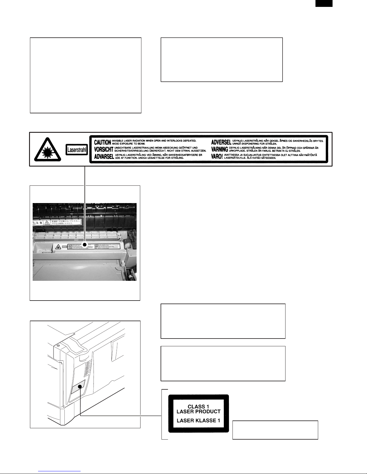
CAUTION
This product is a class 1 laser product that complies with 21CFR 1040.10 and 1040.11 of the CDRH standard and IEC825. This means that this machine does not produce hazardous laser radiation. The use of
controls, adjustments or performance of procedures other than those specified herein may result in hazardous radiation exposure.
This laser radiation is not a danger to the skin, but when an exact focusing of the laser beam is achieved
on the eye’s retina, there is the danger of spot damage to the retina.
The following cautions must be observed to avoid exposure of the laser beam to your eyes at the time
of servicing.
1) When a problem in the laser optical unit has occurred, the whole optical unit must be exchanged as
a unit, not as individual parts.
2) Do not look into the machine with the main switch turned on after removing the developer unit, toner
cartridge, and drum cartridge.
3) Do not look into the laser beam exposure slit of the laser optical unit with the connector connected
when removing and installing the optical system.
4) The middle frame contains the safety interlock switch.
Do not defeat the safety interlock by inserting wedges or other items into the switch slot.
LASER WAVE – LENGTH : 780 ∼ 795
Pulse times : 0.481 ms/6 mm
Out put power : 0.20 ± 0.03 mW
CAUTION
INVISIBLE LASER RADIATION,
WHEN OPEN AND INTERLOCKS DEFEATED.
AVOID EXPOSURE TO BEAM.
VORSICHT
UNSICHTBARE LASERSTRAHLUNG,
WENN ABDECKUNG GEÖFFNET UND
SICHERHEITSVERRIEGELUNG ÜBERBRÜCKT.
NICHT DEM STRAHL AUSSETZEN.
VARO !
AVATTAESSA JA SUOJALUKITUS
OHITETTAESSA OLET ALTTIINA
NÄKYMÄTTÖMÄLLE LASERSÄTEILYLLE ÄLÄ
KATSO SÄTEESEEN.
ADVARSEL
USYNLIG LASERSTRÅLNING VED ÅBNING, NÅR
SIKKERHEDSBRYDERE ER UDE AF
FUNKTION. UNDGÅ UDSAETTELSE FOR
STRÅLNING.
VARNING !
OSYNLIG LASERSTRÅLNING NÄR DENNA DEL
ÄR ÖPPNAD OCH SPÄRREN ÄR URKOPPLAD.
BETRAKTA EJ STRÅLEN. – STRÅLEN ÄR FARLIG.
,
DP1200/1500
At the production line, the output power
of the scanner unit is adjusted to 0.57
MILLI-WATT PLUS 20 PCTS and is
maintained constant by the operation of
the Automatic Power Control (APC).
Even if the APC circuit fails in operation
for some reason, the maximum output
power will only be 15 MILLI-WATT 0.1
MICRO-SEC. Giving an accessible
emission level of 42 MICRO-WATT
which is still-less than the limit of
CLASS-1 laser product.
Caution
This product contains a low power laser
device. To ensure continued safety do not
remove any cover or attempt to gain access
to the inside of the product. Refer all
servicing to qualified personnel.
The foregoing is applicable only to the 220V
230V model and 240V model.
model
VAROITUS! LAITTEEN KÄYTTÄMINEN MUULLA
KUIN TÄSSÄ KÄYTTÖOHJEESSA MAINITULLA
TAVALLA SAATTAA ALTISTAA KÄYTTÄJÄN
TURVALLISUUSLUOKAN 1 YLITTÄVÄLLE
NÄKYMÄTTÖMÄLLE LASERSÄTEILYLLE.
VARNING - OM APPARATEN ANVÄNDS PÅ ANNAT
SÄTT ÄN I DENNA BRUKSANVISNING
SPECIFICERATS, KAN ANVÄNDAREN UTSÄTTAS
FÖR OSYNLIG LASERSTRÅLNING, SOM
ÖVERSKRIDER GRÄNSEN FÖR LASERKLASS 1.
LUOKAN 1 LASERLAITE
KLASS 1 LASER APPARAT

CONTENTS
1. GENERAL ................................................................................................................... 1-1
1. DP1200/1500 major functions .......................................................................................... 1-1
2. System Configuration ....................................................................................................... 1-1
2. SPECIFICATIONS ....................................................................................................... 2-1
1. Basic specifications of copier ........................................................................................... 2-1
3. CONSUMABLE PARTS .............................................................................................. 3-1
1. Supply system table ......................................................................................................... 3-1
2. Environmental .................................................................................................................. 3-1
3. Production control number (lot No.) identification ............................................................. 3-1
4. TD cartridge replacement ................................................................................................. 3-2
4. EXTERNAL VIEWS AND INTERNAL STRUCTURES................................................ 4-1
1. Appearance ...................................................................................................................... 4-1
2. Internal ............................................................................................................................. 4-1
3. Operational panel ............................................................................................................. 4-2
4. Motors and solenoids ....................................................................................................... 4-3
5. Sensors and switches....................................................................................................... 4-4
6. PWB unit .......................................................................................................................... 4-5
7. Cross sectional view......................................................................................................... 4-6
5. UNPACKING AND INSTALLATION
1. A WORD ON COPIER INSTALLATION ............................................................................ 5-1
2. CHECKING PACKED COMPONENTS AND ACCESSORIES .......................................... 5-1
3. UNPACKING .................................................................................................................... 5-1
4. REMOVING PROTECTIVE PACKING MATERIALS ......................................................... 5-1
5. DEVELOPER UNIT INSTALLATION ................................................................................. 5-2
6. TONER CARTRIDGE INSTALLATION.............................................................................. 5-3
7. LOADING COPY PAPER ................................................................................................. 5-3
8. POWER TO COPIER ....................................................................................................... 5-4
9. CONNECTING THE INTERFACE CABLE (DP1200 Only) ............................................... 5-4
6. INSTALLING THE PRINTER DRIVER SOFTWARE (DP1200 Only) ......................... 6-1
1. Description of the printer driver ........................................................................................ 6-1
2. Checking the hardware and software requirements.......................................................... 6-1
3. Installing the printer driver ................................................................................................ 6-1
4. Printer driver group........................................................................................................... 6-3
5. Parallel interface ............................................................................................................... 6-3

7. OPERATIONAL DESCRIPTIONS ............................................................................... 7-1
1. Outline of operation .......................................................................................................... 7-1
2. Scanner section................................................................................................................ 7-2
3. Laser unit ......................................................................................................................... 7-2
4. Fuser section.................................................................................................................... 7-3
5. Paper feed section and paper transport section ............................................................... 7-4
6. Printing process ............................................................................................................... 7-7
8. DISASSEMBLY AND ASSEMBLY .............................................................................. 8-1
1. High voltage section ......................................................................................................... 8-1
2. Operation panel section.................................................................................................... 8-4
3. Optical section .................................................................................................................. 8-5
4. Fusing section .................................................................................................................. 8-6
5. Tray paper feed/Transport section ..................................................................................... 8-9
6. Manual paper feed section ............................................................................................... 8-13
7. Rear frame section ........................................................................................................... 8-17
8. Power section ................................................................................................................... 8-18
9. ADJUSTMENTS .......................................................................................................... 9-1
1. Optical section .................................................................................................................. 9-1
2. Copy density adjustment .................................................................................................. 9-8
3. High voltage adjustment ................................................................................................... 9-9
10. SIMULATION, TROUBLE CODES .............................................................................. 10-1
1. Entering the simulation mode ........................................................................................... 10-1
2. List of simulations ............................................................................................................. 10-2
3. Contents of simulations .................................................................................................... 10-3
4. TROUBLE CODES........................................................................................................... 10-13
11. USER PROGRAM ....................................................................................................... 11-1
12. MAINTENANCE .......................................................................................................... 12-1
1. Maintenance table ............................................................................................................ 12-1
2. Maintenance display system ............................................................................................ 12-1
13. ELECTRICAL SECTION ............................................................................................. 13-1
1. Block diagram................................................................................................................... 13-1
2. Circuit descriptions ........................................................................................................... 13-3
14. CIRCUIT DIAGRAM .................................................................................................... 14-1
DP1200/1500
[1]GENERAL
1.DP1200/1500 major functions
Item
Model
DP1200 12CPM MB
DP1500 15CPM MB Opt Opt Opt
Descriptions of items
CPM: Copy speed (Copies Per Minute)
SB/MB: SB = Manual feed single bypass, MB = Manual feed multi bypass
2 tray:Second cassette unit. The 1 tray unit (MY-1019) is optionally available.
SPF (ADF): Original feed unit (Automatic document feeder)
GDI with USB:GDI printer function with USB. The GA-1090 (GDI + USB kit) is optionally available.
SOPM:Scan One Print Many function (Many copies are made by one scan.)
PCL6 with USB:PCL printer function with USB. The GA-1100 (PCL6 + USB kit) is optionally available.
FAX: FAX unit. The GD-1100 (FAX unit) is optionally available.
Descriptions of table
Standard provision
:
No function or no option available
:
Opt: Option
* PCL6 with USB (GA-1100) + FAX (GD-1100) is not available.
CPM SB/MB 2 tray SPF (ADF)
GDI without
USB
GDI with
USB
PCL6 with
USB
Opt
2. System Configuration
SOPM
FAX
Opt
(Options)
MR-2013
(DP-1200/1500)
GD-1100
GA-1100
MY-1019
GA-1090
1 – 1

[2]SPECIFICATIONS
1.Basic specifications of copier
A.Basic specifications
Item Spec.
Type Desktop
Copy system Dry, electrostatic
Segment (class) Digital personal copier
External dimensions (W x D x H) (mm)
Weight
B.Operation specification
SectionItem Details Spec.
Paper feed
system
Paper size A4, B5, A5 (Landscape)
Paper weight 56 – 80g/m
Paper feed capacity 250 sheets
Kinds Standard paper, specified paper, recycled paper
Remark User adjustment of paper guide available
Paper size A4, B5, A5, B6, A6 (Landscape)
Paper weight 52 – 128g/m
Paper feed capacity 50 sheets
Kinds 1
Remark User adjustment of paper guide available
Paper size 8-1/2" x 14", 8-1/2 x 11", 8-1/2" x 5-1/2" (Landscape)
Paper weight 15 – 21 lbs.
Paper feed capacity 250 sheets
Kinds Standard paper, specified paper, recycled paper
Remark User adjustment of paper guide available
Paper size
Paper weight 14 – 34.5 lbs.
Paper feed capacity 50 sheets
Kinds 1
Remark User adjustment of paper guide available
Paper
feed
section
Tray paper feed
section
AB system
Multi bypass paper
feed section
Tray paper feed
section
Inch system
Multi bypass paper
feed section
DP1200: 293mm x 518mm x 445mm (TBD)
DP1500: 293mm x 518mm x 483mm (TBD)
DP1200: Approx. 17.4kg (TBD)
DP1500: Approx. 19kg (TBD)
DP1200, DP1500: 1 tray (250 sheets) + multi bypass (50 sheets)
Standard paper, specified paper, recycled paper, OHP, Label,
8-1/2" x 14", 8-1/2 x 11", 8-1/2" x 5-1/2", 3-1/2" x 5-1/2"
(Landscape)
Standard paper, specified paper, recycled paper, OHP, Label,
DP1200/1500
2
2
Postal card
Postal card
1:OHP, Label, Postal card: each 1 pc.
As special media have wide variety of forms by country or region, they may not be used in some cases.
2 – 1

DP1200/1500
Section Item Details Spec.
Exit way Face down
Paper exit section
Capacity of output
tray
Original set Center Registration (left edge)
Max. original size B4 (10″ × 14″)
Originals
Original kinds Sheet and book
Original size
detection
Scanning system CCD sensor scanning by lighting lamp scanner
CCD sensor Resolution 400 dpi
Optical
section
Scanning
section
Lighting lamp
Type Xenon lamp
Voltage 1.5kV
Power consumption 11 ± 3W
Gradation 256 gradations/8bit
Writing
section
Writing system Writing to OPC drum by the semiconductor laser
Laser unit Resolution 600 dpi
Photoconductor
Type OPC (30φ)
Life25k
Image forming
Charger
Charging system Saw -tooth charging with a grid, / (–) scorotron discharge
Transfer system (+) DC corotron system
Separation system (–) DC corotron system
Developing Developing system Dry, 2-component magnetic brush development system
Cleaning Cleaning system Counter blade system (Counter to rotation)
Fusing system Heat roller system
Upper heat roller Type Teflon roller
Fusing section
Lower heat roller Type Silicon rubber roller
Type Halogen lamp
Heater lamp
Voltage100V/240V
Power consumption 800W
Power source
Voltage Local AC voltage
Frequency Common use for 50 and 60Hz
Max.DP1200/DP1500: 1000W
Electrical section
Power consumption
Average (operating) *
Stand-by mode
(initial condition) *
Pre-heat mode *
1)
Auto power shut-off mode *
*1) May fluctuate due to environmental conditions and the input voltage.
1)
1)
1)
DP1500: 310Wh/H, DP1200: 270Wh/H
100 sheets
None
DP1200/DP1500: 70Wh/H
DP1200/DP1500: 40Wh/H
DP1200/DP1500: 18Wh/H
2 – 2

C.Copy performance
Section Item Details Spec.
Copy magnification
Manual steps (manual,
photo)
Copy speedFirst copy time
AB system: A4
(Landscape)
B5 (Landscape)Copy speed (CPM)
Inch system 8-1/2”
× 14” (Landscape)
8-1/2” × 11”
(Landscape)
Max. continuous copy
quantity
Fixed magnification ratios
Zooming magnification ratios 50 ~ 200% (151 steps in 1% increments)
Copy speed (CPM)
Copy speed (CPM)
Copy speed (CPM)
Void area
DP1200/1500
3R + 2E (AB system: 50, 70, 81, 100, 141, 200%)
(Inch system: 50, 64, 78, 100, 129, 200%)
5 steps
9.6 sec. or below (A4), 9.4 sec. or below (8-1/2"
Tray paper feed
Manual paper feed
Same size DP1200: 12DP1500: 15
EnlargementDP1200: 12DP1500: 15
Reduction DP1200: 11DP1500: 15
Same size DP1200: 12DP1500: 15
EnlargementDP1200: 12DP1500: 15
Reduction DP1200: 12DP1500: 15
Same size DP1200: 10DP1500: 12
EnlargementDP1200: 10DP1500: 12
Reduction DP1200: 10DP1500: 12
Same size DP1200: 12DP1500: 15
EnlargementDP1200: 12DP1500: 15
Reduction DP1200: 12DP1500: 15
Leading edge 1 4 mm
Trailing edge
14") (Pre-heat mode: 16 sec. or below / Auto power-
shut-off mode: 23 sec. or below)
10.0 sec (Pre-heat mode: 16 sec. or below / Auto
power-shut-off mode: 23 sec. or below)
99
4 mm or less
Void
Image loss
Side edge void area
OC mode Leading edge
SPF mode
Leading edge
4 mm or less
(per side)
Same size: 3.0mm or less / Enlarge (200%): 2.0mm
or less / Reduction (50%): 6.0mm or less
Same size: 4.0mm or less / Enlarge (200%): 3.0mm
or less / Reduction (50%): 8.0mm or less
2 – 3
DP1200/1500
[3]CONSUMABLE PARTS
1.Supply system table
No. Name Model name Life Package unit Remark
1 Toner Cartridge PS-ZT1200
2 Developer D-1200 10
3 Drum Kit OD-1200 10
6.5K
25K
(6%)
25K
10 Life based on 6% coverage of A4 original.
2.Environmental
The environmental conditions for assuring the copy quality and the
machine operations are as follows:
(1) Normal operating condition
Temperature: 20°C~25
Humidity: 65 5%RH
(2) Acceptable operating condition
Humidity (RH)
85%
60%
20%
10°C 30°C 35°C
(3) Transportation condition
Humidity (RH)
90%
60%
3.Production control number (lot No.)
identification
áDeveloping cartridgeñ
Production month
Production day
Destination code
(Dealer, distributor, OEM, etc.)
Production place
(SOCC: Fixed to B.)
End digit of year
Version No.
*:Destination
Division No.
EX Destination
Option Destination
áDrum cartridgeñ
The label on the drum cartridge shows the date of production.
(SOCC production)
A same pack G
B same pack H
AP
BQ
15%
–25°C 30°C 40°C
(4) Supply storage condition
Humidity (RH)
90%
20%
–5°C 45°C
Production month
Production day
Destination code
(Dealer, distributor, OEM, etc.)
Production place
(SOCC: Fixed to B.)
End digit of year
Version No.
áJAPAN productionñ
Ver. A 9 1 1 0001 X
Production month
(1-9=Jan. -Sep. 0=Oct. X=Nov. Y=Dec)
Serial number of month
Fixed to 1.
Pack division
(See table below)
End digit of year
Version No.
3 – 1
DP1200/1500
Division No.
Ex production 1
Option 2
Same pack 3
Production control
label attachment position
4. TD cartridge replacement
1) Open the front and side cabinets of the copier.
2) Keep holding Toner lover, and
3) Carefully pull out Toner unit from the copier.
2
3
1
4) Put Toner unit in a collection bag immediately after removing it from
the copier
Production control
label attachment position(*1)
∗1 The production control label is not attached to the cartridge of a
China product.
Note: Never carry exposed Toner unit. Be sure to put it in the col-
lection bag.
3 – 2
DP1200/1500
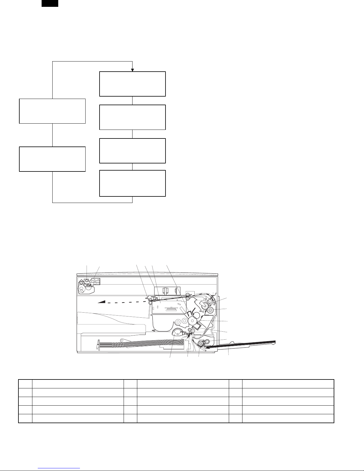
[4] EXTERNAL VIEWS AND INTERNAL STRUCTURES
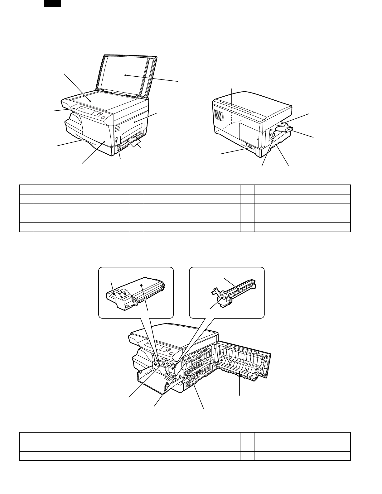
1. Appearance
(1)
(2)
(4)
(6)
(5)
(1) Original table (2) Original cover (3) Side cover
(4) Operation panel (5) Front cover (6) Paper tray
(7) Side cover open button (8) Paper guides (9) Handle
(10) Paper output tray (11) Paper output tray extension (12) Power cord socket
(13) Power switch
(7)
(3)
(8)
(12)
(9)
(13)
(9)
2. Internal
(10)
(11)
(1)
(2)
(5)
(6)
(1) TC cartridge lock release button (2) TD cartridge (3) Drum cartridge
(4) Drum cartridge handle (5) Paper feed roller (6) Fusing unit release lever
(7) Charger cleaner (8) Transfer charger
(3)
(4)
(8)
(7)
4 – 1
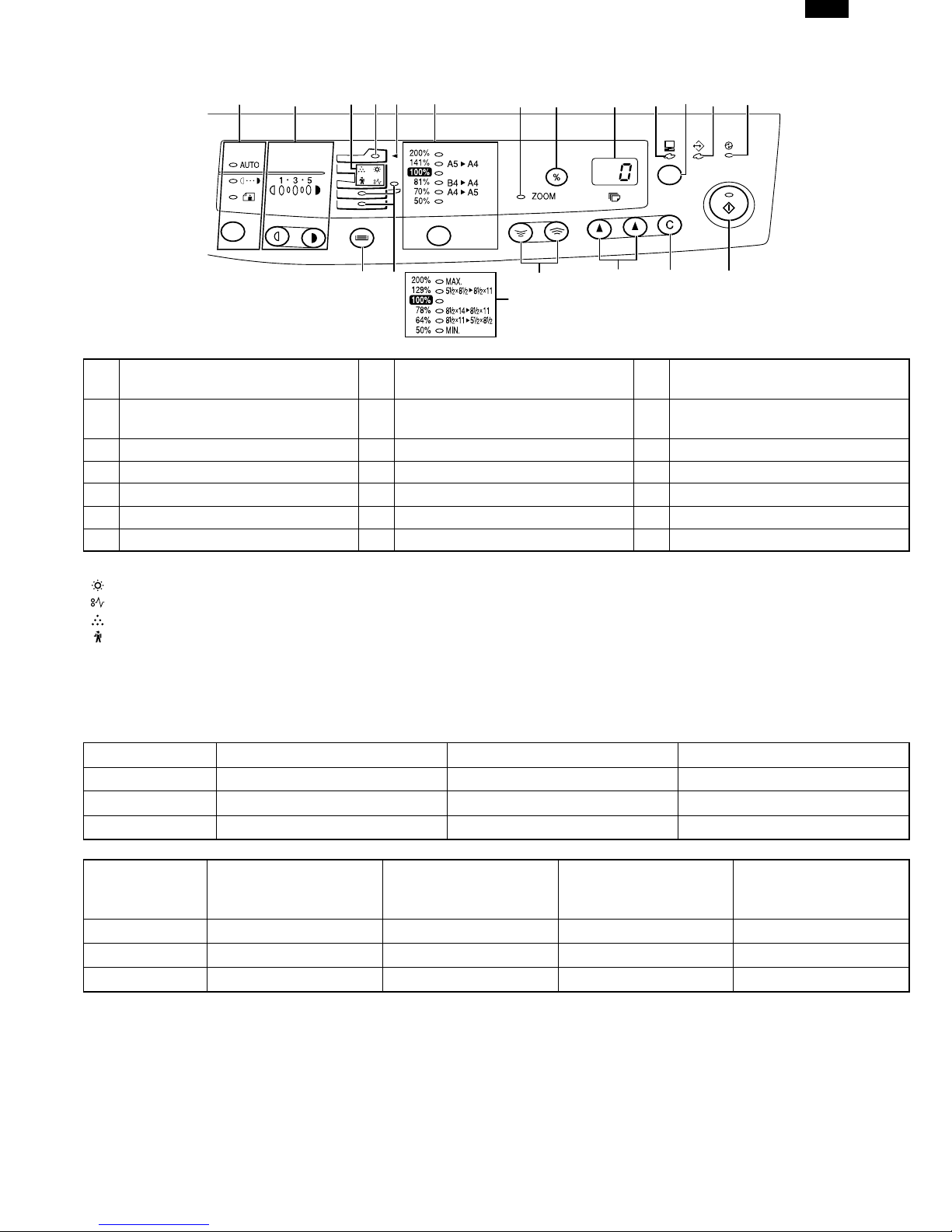
3. Operational panel
DP1200/1500
(1) (2) (3)
(14)
(4)
(15)
(5)
(6)
(7) (8)
(16) (17) (18) (19)
(6)
(9)
(10)
(11)
(12)
(13)
Inch system
Exposure mode selector key
(1)
and indicators
(4) SPF indicator (5) SPF misfeed indicator (6)
(7) Zoom indicator (8) Copy ratio display (%) key (9) Display
(10) ON LINE indicator (11) ON LINE key (12) DATA indicator
(13) Power save indicator (14) Tray select key (15) Paper feed location indicators
(16) Zoom keys (17) Copy quantity keys (18) Clear key
(19) Print key and ready indicator
Light and dark keys and
(2)
exposure indicators
(3) Alarm indicators
Copy ratio selector key and
copy ratio indicators
∗1
∗1
Developer replacement required indicator
Misfeed indicator
Toner cartridge replacement required indicator
Maintenance indicator
∗2 ON: Indicates that the machine is in the energy saving (pre-heat) mode.
Blink: Indicates that the machine is in the process of resetting from the energy saving mode or just after supplying the power.
OFF: Indicates that resetting from the energy saving mode is completed and that the fusing temperature is in ready state.
The combinations of the above display lamps are as follows: (● = ON, ✕ = OFF)
Lamp Immediately after power ON Ready Copying
Pre-heat lamp Blink ✕✕
Ready lamp ●●✕
Other lamps ●●●
Copy is started during
resetting from energy
saving mode
Lamp
Energy saving mode (Pre-
heating)
Energy saving mode
(Auto power shut off)
Resetting from energy
saving mode
Pre-heat lamp ●●Blink Blink
Ready lamp ●✕●✕
Other lamps ●✕●●
4 – 2
DP1200/1500
4. Motors and solenoids
(3)
(2)
(4)
(1)
(5)
(7)
(6)
No. Part name Control signal Function,operation
(1) Main motor MM Drives the copier.
(2) Mirror motor MRMT Drives the optical mirror base (scanner unit).
(3) Toner motor TM Supplies toner.
(4) Cooling fan motor VFM Cools the optical section.
(5) Resist roller solenoid RRS Resist roller rotation control solenoid
(6) Paper feed solenoid CPFS1 Cassette Paper feed solenoid
(7) Multi paper feed solenoid MPFS Multi manual pages feed solenoid
4 – 3
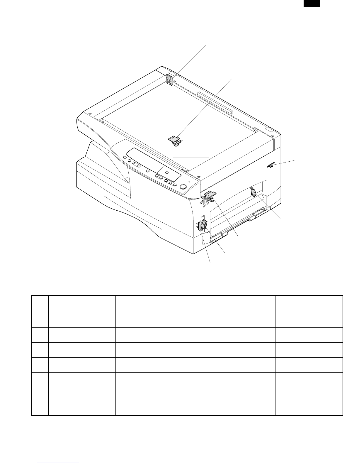
5. Sensors and switches
DP1200/1500
(1)
(2)
(3)
(4)
(5)
(6)
(7)
No. Name Signal Type Function Output
Mirror home position
(1)
sensor
(2) POD sensor POD Transmissions sensor Paper exitdetection “H” at paper pass
(3) PPD2 sensor PPD2 Transmission sensor
Cassette detection
(4)
switch
(5) PPD1 sensor PPD1 Transmission sensor
(6) Door switch DSW Micro switch
(7) Door switch DSW Micro switch
MHPS Transmission sensor
CED1 Microswitch
Mirror (scanner unit)
home position detection
Paper transport
detection 2
Cassette installation
detection
Paper transport
detection 1
Door open/close
detection (safety switch
for 5V)
Door open/close
detection (safety switch
for 24V)
“H” at home position
“L” at paper pass
“H” at cassette insertion
“L” at paper pass
1 or 0V of 5V at door
open
1 or 0V of 24V at door
open
4 – 4
DP1200/1500
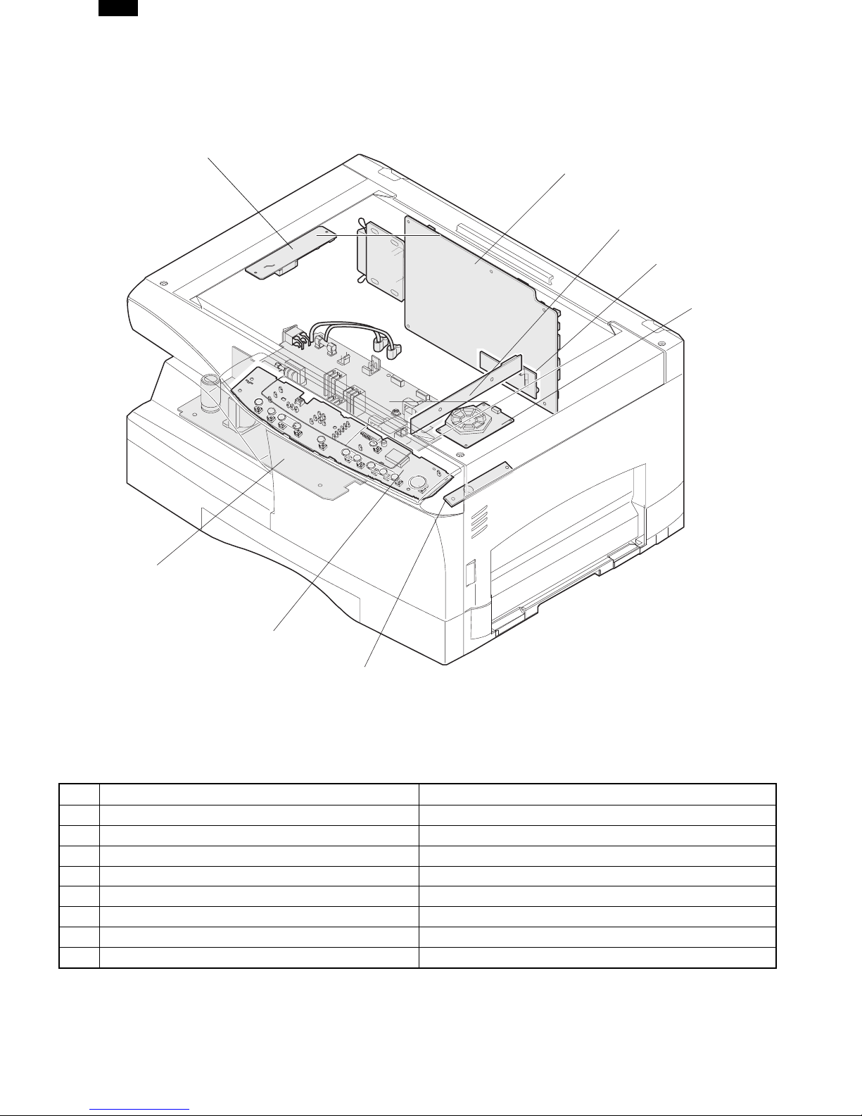
6. PWB unit
(1)
(2)
(5)
(8)
(6)
(4)
(3)
(7)
No. Name Function
(1) Exposure lamp invertor PWB Exposure lamp (Xenon lamp) control
(2) Main PWB (MCU) Copier control
(3) Operation PWB Operation input/display
(4) Power PWB AC power input, DC voltage control, High voltage control
(5) CCD sensor PWB For image scanning
(6) LSU motor PWB For polygon motor drive
(7) TCS PWB For toner sensor control
(8) LSU PWB For laser control
4 – 5
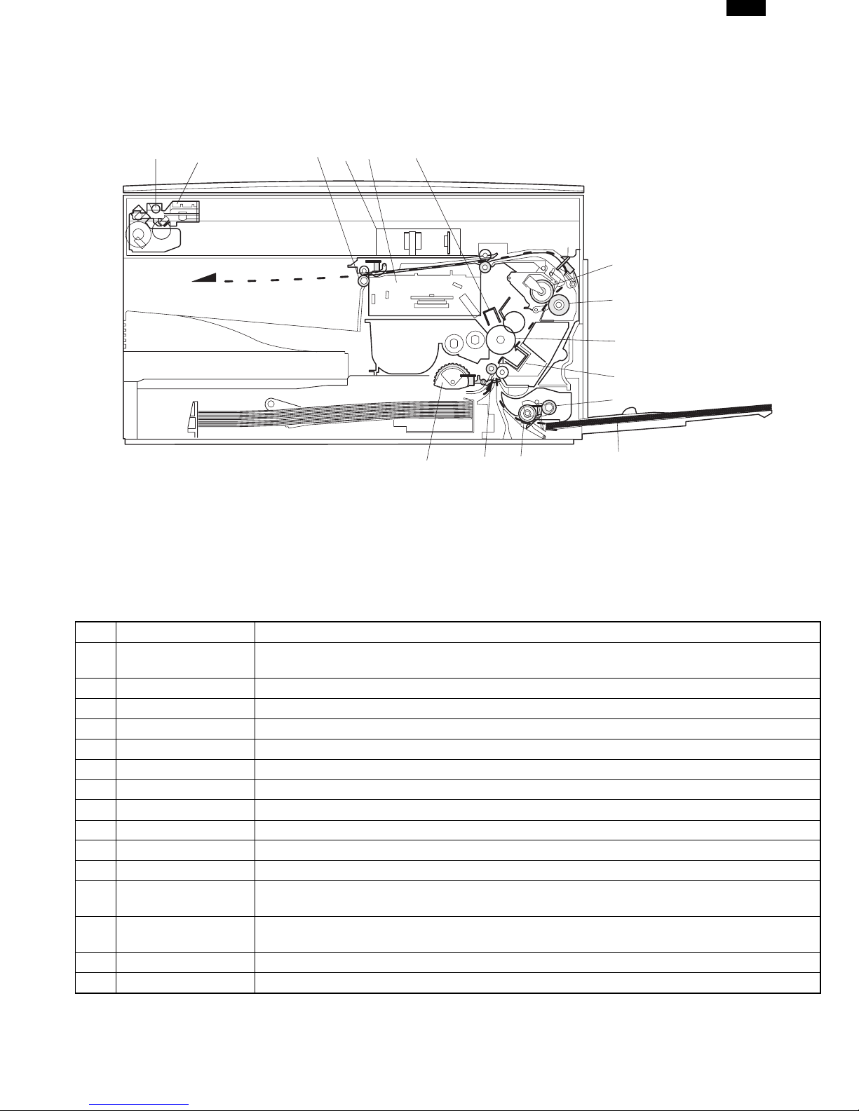
7. Cross sectional view
DP1200/1500
(2)
(1)
(5)
(3)
(4)
(6)
(15)
(14)
(13)
(7)
(8)
(9)
(10)
(11)
(12)
No. Part name Function and operation
(1) Scanner unit
(2) Exposure lamp Exposure lamp (Xenon lamp) Illuminates original
(3) Lens unit Scans the original image with the lens and the CCD.
(4) LSU (Laser unit) Converts the original image signal into laser beams and writes onto the drum.
(5) Paper exit roller Roller for paper exit
(6) Main charger Provides negative charges evenly to the drum surface.
(7) Heat roller Fuses toner on the paper. (Teflon roller)
(8) Pressure roller Fuses toner on the paper. (Silicon rubber roller)
(9) Drum Forms images.
(10) Transfer unit Transfers images onto the drum.
(11) Pickup roller Picks up the manual feed paper. (In multi feed only)
(12)
(13)
(14) PS roller unit Takes synchronization between the lead edge and the rear edge of the paper.
(15) Paper feed roller Picks up a sheet of paper from the cassette.
Manual paper feed
tray
Manual paper feed
roller
Illuminates the original with the copy lamp and passes the reflected light to the lens unit
(CCD).
Tray for manual feed paper
Transport the paper from the manual paper feed port.
4 – 6
DP1200/1500
[5] UNPACKING AND INSTALLATION
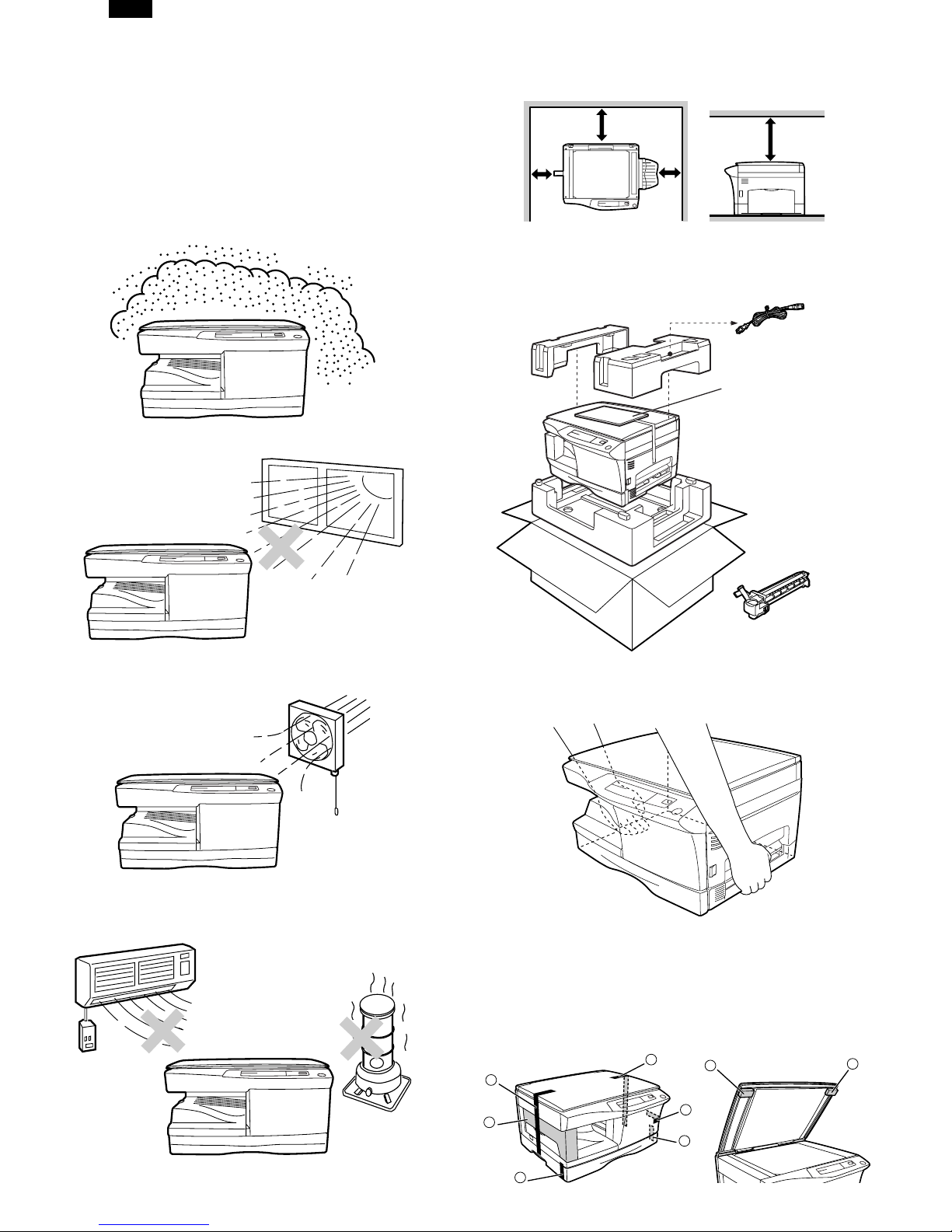
1. A WORD ON COPIER INSTALLATION
Improper installation may damage the copier. Please note the
following during initial installation and whenever the copier is
moved.
Do not install your copier in areas that are:
● damp, humid, or very dusty
● exposed to direct sunlight
Be sure to allow the required space around the machine for
servicing and proper ventilation.
8"(20cm)
8"(20cm)
4"
(10cm)
4"
(10cm)
2. CHECKING PACKED COMPONENTS AND
ACCESSORIES
Open the carton and check if the following components and accessories are included.
Power cord
Operation manual
(CD-ROM : DP1200 Only)
Copier
● poorly ventilated
● subject to extreme temperature or humidity changes, e.g.,
near an air conditioner or heater.
Drum cartridge
(installed in copier)
3. UNPACKING
Unpack the copier and carry it to the installation location by
holding the handles on both sides of the copier.
4. REMOVING PROTECTIVE PACKING
MATERIALS
1) Remove pieces of tape (a), (b), (c), (d) and (e) and protec-
tive cover (f). Then open the original cover and remove
protective materials (g) and (h).
c
a
g
h
f
e
d
b
5 – 1
DP1200/1500
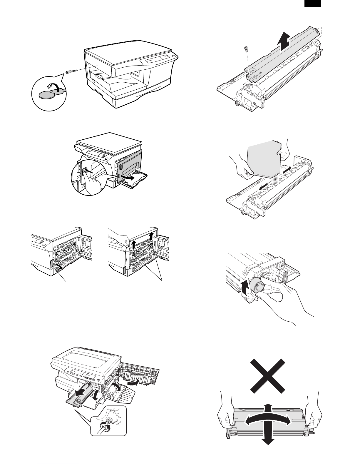
2) Use a coin (or suitable object) to remove the screw.
Store the screw in the paper tray because it will be used if
the copier has to be moved.
3) Open the bypass tray and then open the side cover whilst
pressing the side cover open button.
8) Remove Upper developer unit.
9) Shake the aluminum bag to stir developer
10) Supply developer from the aluminum bag to the top of the
MX roller evenly.
4) Remove the CAUTION tape from the front cover and
remove the two protective pins from the fusing unit by pulling the strings upward one at a time.
CAUTION tape
Protective pins
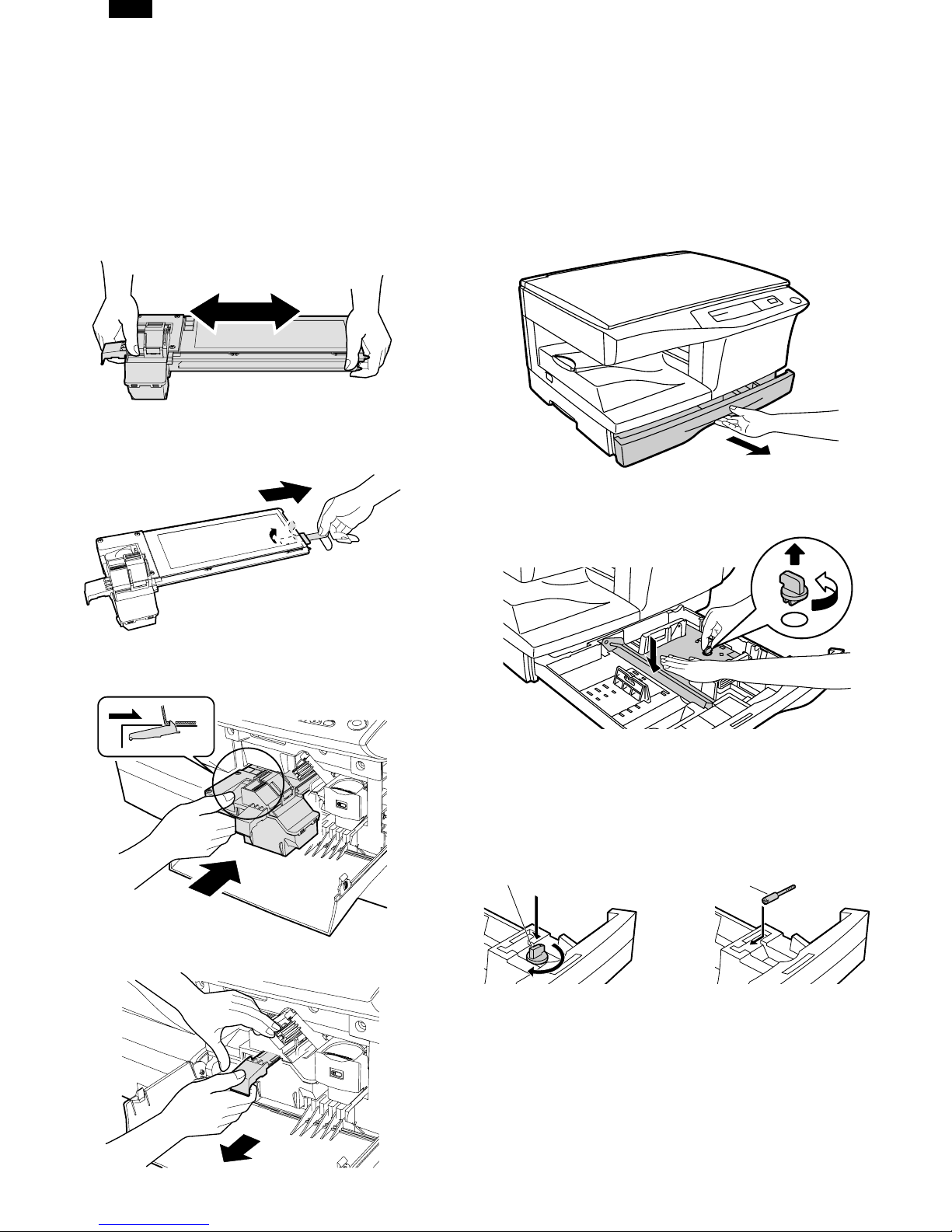
5. DEVELOPER UNIT INSTALLATION
1) 2) 3) Open the side and front cabinets of the copier.
4) Remove the locking tape of the developer unit.
5) Remove the screw which is fixing the copier and
Developer unit.
6) Remove Developer unit slowly from the copier.
Note: Be careful not to splash developer outside Developer
unit.
11) Attach Upper developer unit and fix it with a screw.
12) Rotate the MG roller gear to distribute developer evenly.
Note: Never rotate the gear in the reverse direction.
Note: When carrying Developer unit, do not tilt it extremely
as shown with the arrow in the figure below.
(Prevention of splash of developer)
5
1
3
4
7) Remove the screw (1 pc).
2
5 – 2
DP1200/1500
13) Insert Developer unit carefully into the copier.
Note: Quick insertion may result in splash of developer. Be
sure to insert carefully.
14) Confirm that Developer unit is completely inserted to the
bottom of the machine, fix Developer unit and the machine
with a screw.
15) Completion of Developer unit installation
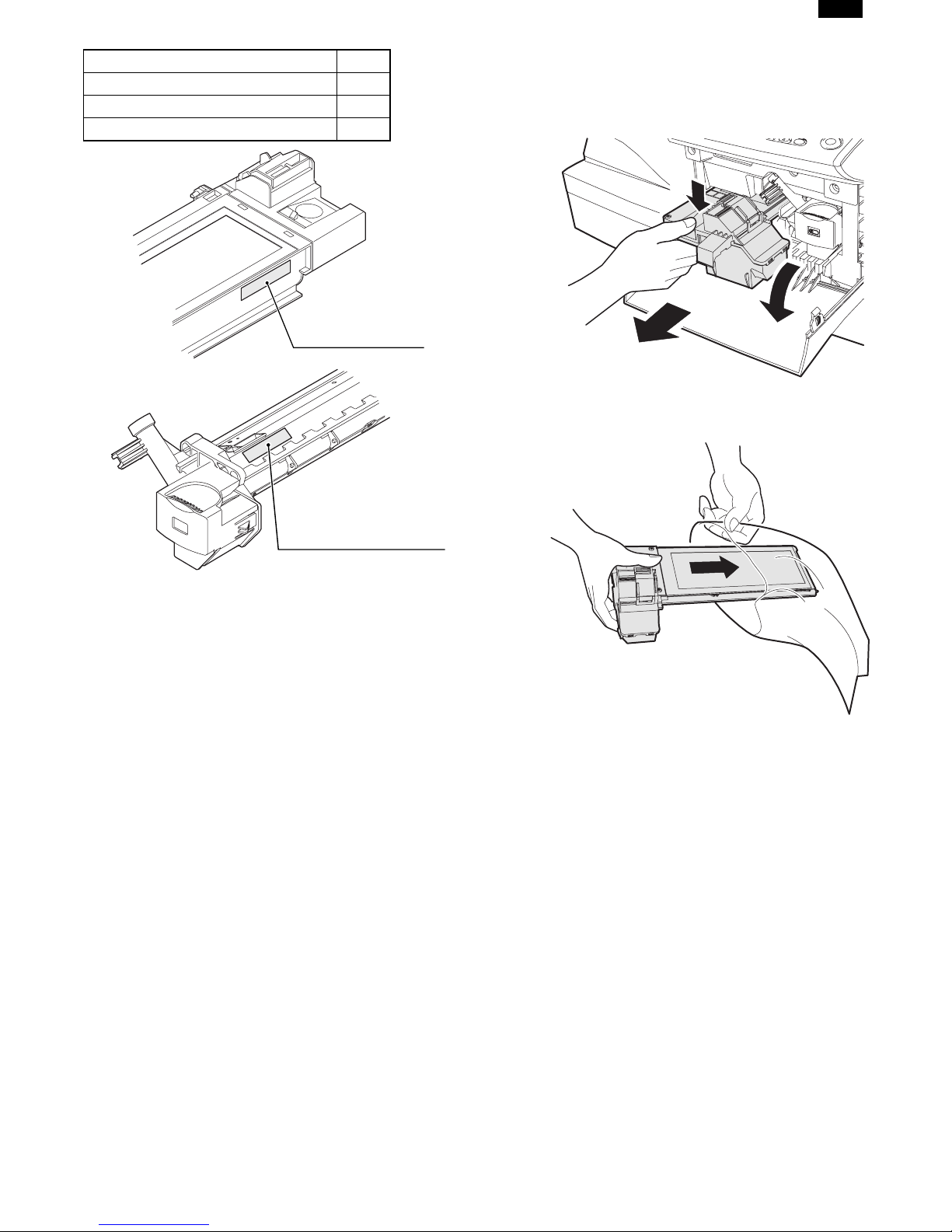
6. TONER CARTRIDGE INSTALLATION
1) To prevent against uneven distribution of toner, hold Toner
unit with both hands and shake it several times horizontally.
2) Hold the section of Toner unit shown in the figure below,
remove the packing tape, and remove the cushion.
3) Remove the tape securing the shutter, and pull out the
cushion in the arrow direction.
Note: Do not hold and carry the shutter. Otherwise the shut-
ter may drop and Toner unit may drop.
7) Completion of Toner unit installation
Close the front and side cabinets.
7. LOADING COPY PAPER
Note: This copier is equipped with two paper trays. Load copy
paper into the two paper trays.
1) Raise the handle of the paper tray and pull the paper tray
out until it stops.
2) Remove the pressure plate lock. Rotate the pressure plate
lock in the direction of the arrow to remove it while pressing
down the pressure plate of the paper tray.
4) Insert Toner unit carefully into the copier.
5) Insert until the hook is engaged with the copier as shown in
the figure below.
6) Pull out the shutter in the arrow direction.
3) Store the pressure plate lock which has been removed in
step 2 and the screw which has been removed when unpacking (see page 5-2, step 2 of REMOVING PROTECTIVE PACKING MATERIALS) in the front of the paper tray.
To store the pressure plate lock, rotate the lock to fix it on
the relevant location.
Pressure plate lock
Screw
4) Adjust the paper guides on the paper tray to the copy paper
width and length.
Squeeze the lever of paper guide (A) and slide the guide to
match with the width of the paper.
Move paper guide (B) to the appropriate slot as marked on
the tray.
5 – 3
Paper guide (B)
Paper guide (A)
5) Fan the copy paper and insert it into the tray. Make sure the
edges go under the corner hooks.
Note: Do not load paper above the maximum height line ( ).
Exceeding the line will cause a paper misfeed.
DP1200/1500
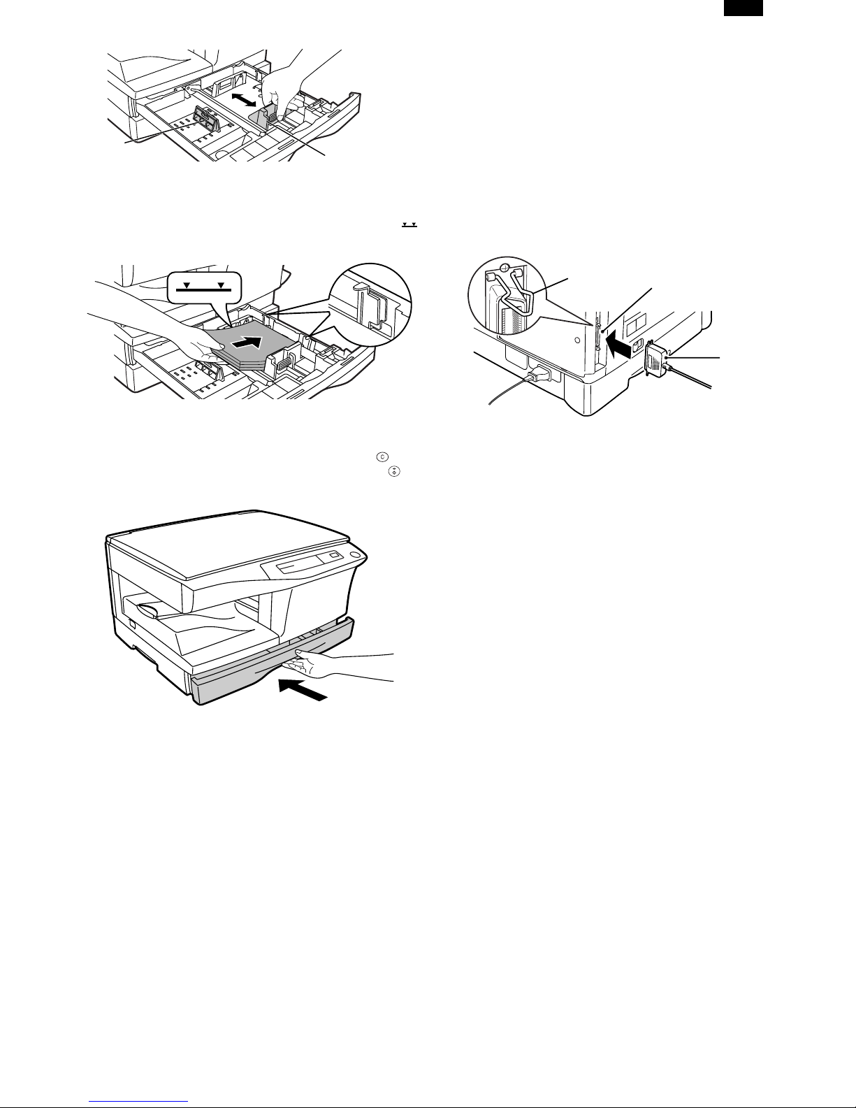
9. CONNECTING THE INTERFACE CABLE
(DP1200 Only)
● For specifications of the parallel interface, see page 6-3.
1) Check that the power switches of both the printer and the
computer are in the OFF position.
2) Plug the parallel interface cable into the printer interface
connector. Fasten the two bail clips at the side of the printer
connector to hold the interface connector in place.
3) Plug the other end of the cable into the parallel interface
connector on your computer. (Refer to your computer
manual for details.)
6) Gently push the paper tray back into the copier.
Note: After loading copy paper, to cancel the blinking “P”
without restarting copying, press the clear ( ) key.
The “P ” in the disp lay wil l go out and t he rea dy ( ) indicator will light up.
Bail clip
Parallel interface connector
Interface connector
Cable
● The printer sends and receives data bi-directionally and
at high speed. Some switch boxes and pass-through
devices cannot support high-speed, bi-directional transfer of data, and using them may cause printing errors.
8. POWER TO COPIER
1) Ensure that the power switch of the copier is in the OFF
position. Insert the attached power cord into the power cord
socket at the rear of the copier.
2) Plug the other end of the power cord into the nearest outlet.
5 – 4
DP1200/1500
[6] INSTALLING THE PRINTER DRIVER
SOFTWARE (DP1200 Only)
1. Description of the printer driver
The printer driver is the software program which runs the
printer. It converts the data in your file into information that the
printer can understand. It also controls communication between
the printer and computer as the data is printed.
2. Checking the hardware and software requirements
You will need the following hardware and software in order to
install the printer driver.
Computer type IBM PC/AT or compatible
computer equipped with a
bi-directional parallel
interface and CD-ROM
drive
Windows type Windows 3.1x, Windows
95, Windows 98, Windows
NT 4.0
CPU 486DX 66 MHz or better
Physical RAM Windows 95, Windows
3.1x: 8 MB (16 MB or
more is recommended.)
Windows 98, Windows NT
4.0: 16MB (32MB or more
is recommended.)
Virtual storage (swap file) 8 MB or moreDisplay 640
´ 480 dots (VGA) or better
Hard disk free space 10 MB or more
The printer driver included in this product cannot be used
under Windows NT3.5x, OS/2, pure MS-DOS and other
operating systems which are not described above.
If you are using some of your computers memory as a RAM
drive, the printer driver may not be allocated the correct
amount of memory. In such a case, reduce the size of your
RAM disk, or do not use the RAM disk. Please refer to your
MS Windows documentation for further information.
3. Installing the printer driver
The software for your printer is provided on CD-ROM.
Before installing the printer driver, be sure to check the following items.
Is the printer connected properly to the computer?
Does the printer have paper?
Is there another GDI printer driver or Windows Printing
System printer driver already installed? If installed,
change the printer port setting.
In this description, the following drive configuration is supposed. Specify proper drives depending on the configuration of
your computer.
Drive R: CD-ROM drive (installation source)
Drive C: Hard disk drive (installation destination)
A. Windows 95/Windows NT 4.0:
1) Load paper into the paper tray of the printer.
2) Turn on the printer.
3) Turn on your computer and start Windows.
Before installing the printer driver, be sure to close all
other applications which may be open.
4) When using Windows 95 on a personal computer with
plug & play
will appear. Insert the installation CD-ROM into the CDROM drive. Click the Next button and follow the on-screen
instructions. Proceed to step 7. If the "Copying Files" window appears during this operation, enter R:\ (if the CDROM is designated as drive R) and click the OK button.
If you use Windows 95 and the "New Hardware Found"
window will appear, click the Driver from Disk Provided
by Hardware Manufacturer button and then click OK.
Proceed to step 6.
If you use Windows 95 and the screen shown above or
the "New Hardware Found" window does not appear,
proceed to step 5.
If you use Windows NT 4.0, proceed to step 5.
Plug & play
This feature is effective if both the computer and
peripheral equipment are equipped with IEEE 1284 compliant parallel interface.
The screen displayed depends on the version of Windows.
5) Insert the installation CD-ROM into the CD-ROM drive.
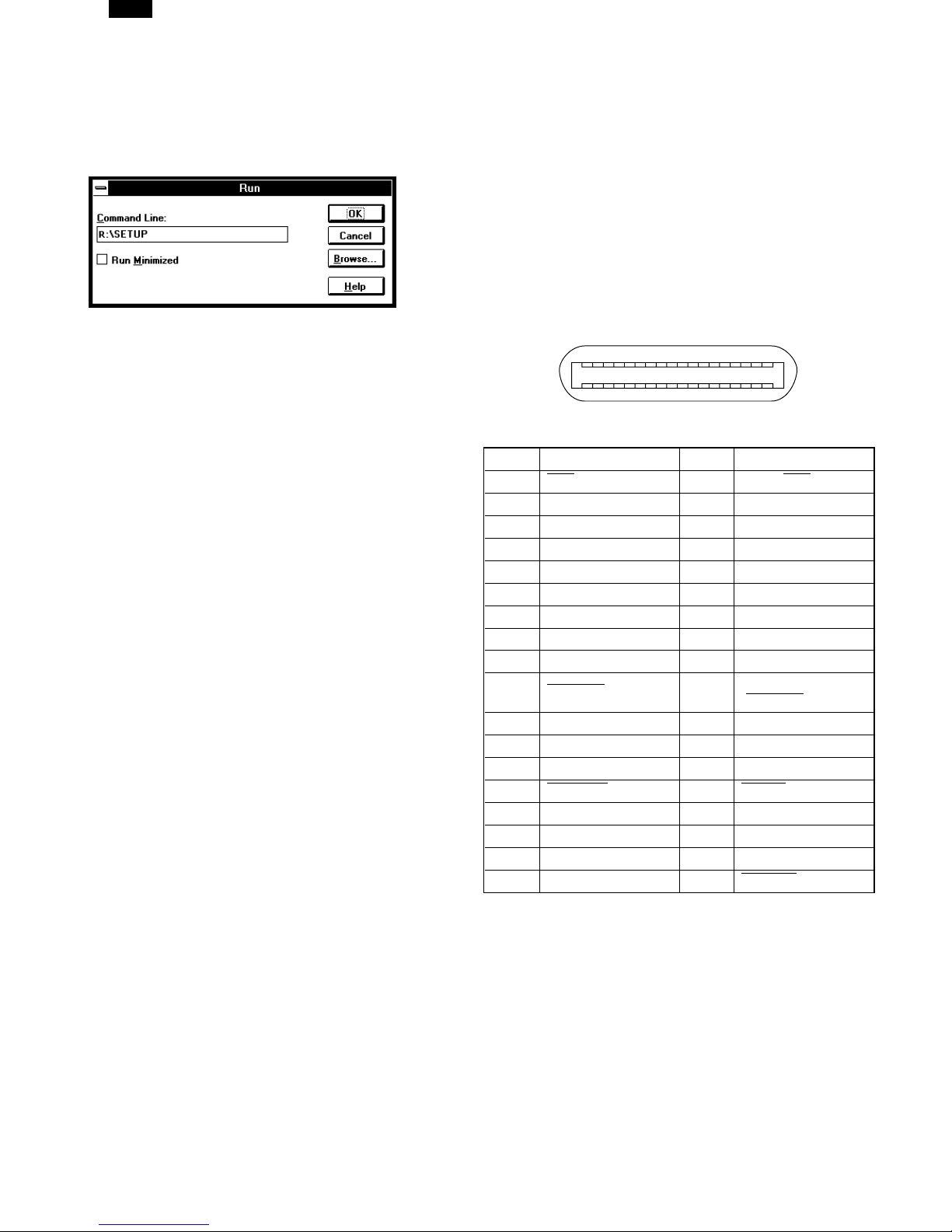
Click the Start button and select Run. When the screen
shown below appears, type R:\SETUP (if the CD-ROM is
designated as drive R) and click the OK button. Proceed
to step 7.
*
, the "Update Device Driver Wizard" window
6 – 1
DP1200/1500
6) "Installation from CD-ROM" window will appear. Insert the
installation CD-ROM into the CD-ROM drive. Type R:\ (if
the CD-ROM is designated as drive R) and click the OK
button. Proceed to step 7.
7) The installation program will start. To install the printer
driver to the default folder, click the Next button. To select
a different folder, select Browse and type in the new path
and folder name. Click OK and say YES to create the
folder, select the Next button to continue.
8) On the display, you will see "printer port to be used". Normally, this is LPT1 and it is selected automatically.
Ensure that Yes is checked to use the printer as the
default printer.
Finally click the Next button.
9) A "Confirm installation" window will be displayed. To continue installation, click the Yes button.
5) Select Search for the best driver for your device and
click the Next button.
6) Insert the installation CD-ROM into the CD-ROM drive.
Select the CD-ROM drive and click the Next button.
7)Windows driver file search will find the device TOSHIBA
e-STUDIO Series. Click the Next button. Proceed to step 9.
8) Insert the installation CD-ROM into the CD-ROM drive.
Click the Start button and select Run. When the window
shown below appears, type R:\SETUP (if the CD-ROM is
designated as drive R) and click the OK button. Proceed
to step 9.
10) When the installation is complete, you will be asked
whether or not to print a test page. If you wish to do so,
click the Yes button. At this time, ensure that paper is
loaded in the paper tray.
11) If the test print completes successfully, click the Finish
button. "The installation of the
TOSHIBA e-STUDIO
Series
Software is complete." window will be displayed. Click the
OK button.
B. Windows 98:
1) Load paper into the paper tray of the printer.
2) Turn on the printer.
3) Turn on your computer and start Windows.
Before installing the printer driver, be sure to close all
other applications which may be open.
4) When using Windows 98 on a personal computer with
*
plug & play
, the "Add New Hardware Wizard" window will
appear. Click the Next button and follow the on-screen
instructions.
If the "Add New Hardware Wizard" window does not appear, proceed to step 8.
Plug & play: For plug & play information, see page 4-1.
9) The installation program will start. To select a different
folder, select Browse and type in the path and folder
name where the printer driver will be installed. Click OK
and say YES to create the folder, select the Next button
to continue. To install the printer driver to the default
folder, click the Next button.
10) On the display, you will see "printer port to be used". Normally, this is LPT1 and it is selected automatically. Ensure
that Yes is checked to use the printer as the default
printer. Finally click the Next button.
11) A "Confirm installation" window will be displayed. To continue installation, click the Yes button.
12) When the installation is complete, you will be asked
whether or not to print a test page. If you wish to do so,
click the Yes button. At this time, ensure that paper is
loaded in the paper tray.
13) If the test print completes successfully, click the Finish
button. "The installation of the TOSHIBA e-STUDIO Series
Software is complete." window will be displayed. Click the
OK button.
C. Windows 3.1x:
1) Load paper into the paper tray of the printer.
2) Turn on the printer and then start Windows on your computer.
Before installing the printer driver, be sure to close all
other applications which may be open.
6 – 2
DP1200/1500
3)Insert the installation CD-ROM into a CD-ROM drive.
4)Choose File from the Menu bar in Program Manager, and
then choose the Run... command.
5)Type R:\SETUP (if the CD-ROM is designated as drive R)
in the command line box and then click the OK button.
6)Select a directory to which the printer driver will be installed and click the Next button. To install it to the default
directory, click the Next button.
7)A “printer port to be used” window will be displayed. Normally, LPT1 is automatically set.
Then ensure that Yes is checked to use this printer as the
default printer.
8)A “Confirm installation” window will be displayed. To continue installation, click Yes.
9)When the installation is complete, restart Windows.
4.Printer driver group
When the printer driver is installed, the TOSHIBA e-STUDIO Series
printer driver group will be created. This group allows the following functions to be executed.
Uninstall
The printer driver can be uninstalled. If the driver is
uninstalled, printing cannot be performed on the printer.
For proper uninstallation, be sure to use uninstallation program of the printer driver group.
Readme
The latest information on the printer driver is included in
this note. Read the Readme first.
Advanced Settings
See help for application support and application problems
that may occur when printing. See help for the applicable
method of usage.
Status Monitor
The printer state and information on current printing are
displayed on the status monitor window.
DOS Emulation Setup
Status Monitor HELP
DOS Emulation HELP
Advanced Settings HELP
5.Parallel interface
This printer uses a bi-directional parallel interface. Use the supplied interface cable.
Connector
36-pin DDK 57LE-40360-730B (D29) female connector or
equivalent connector
Cable
Shielded type bi-directional parallel interface
For best results,, use a printer interface cable which is
IEEE1284 compliant.
Pin configuration
The pin numbers and signal names are listed in the following table.
18
36 19
Pin No.Signal namePin No.Signal name
1 STB19GND (STB RET)
2DATA120GND (DATA1 RET)
3DATA221GND (DATA2 RET)
4DATA322GND (DATA3 RET)
5DATA423GND (DATA4 RET)
6DATA524GND (DATA5 RET)
7DATA625GND (DATA6 RET)
8DATA726GND (DATA7 RET)
9DATA827GND (DATA8 RET)
ACKNLG28
10
11BUSY29GND (BUSY RET)
12PE (Paper End)30GND (PE RET)
13SLTC31INPRM
AUTO LF32 FAULT
14
15(NC)33(NC)
16GND (0 V)34(NC)
17FG35+5 V
18+5 V36
1
GND
ACKNLG RET)
(
SLTC IN
●Be sure to read “Readme” found in the printer driver group
before starting to print from application programs.
6 – 3
[7]OPERATIONAL DESCRIPTIONS
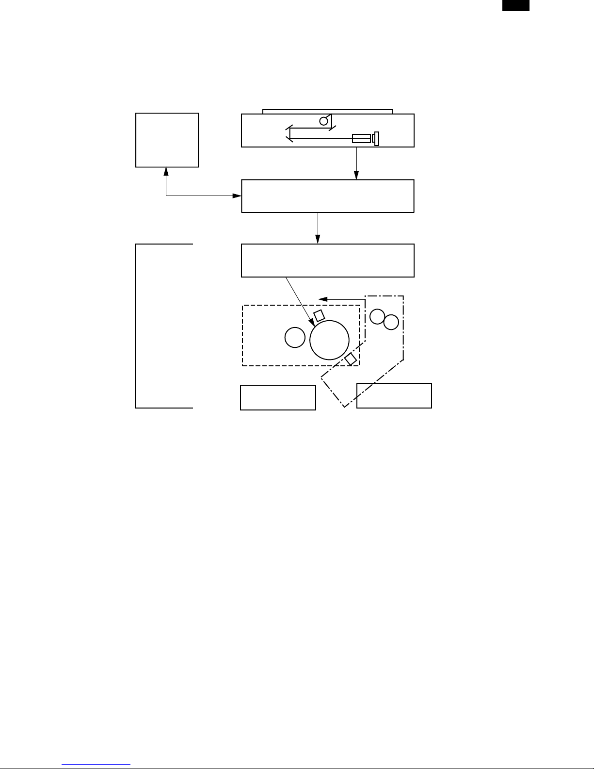
1.Outline of operation
The outline of operation is described referring to the basic configuration.
(Basic configuration)
DP1200/1500
Operation
section
Printer section
Scanner section
MCU (Main control/image process section)
LSU (Laser unit)
Laser diode, Polygon mirror lens
Laser beam
Process section
Cassette paper
feed section
CCD
Paper exit
Fusing section
Paper transport section
Manual paper
feed section
(Outline of copy operation)
Setting conditions
1)Set copy conditions such as the copy quantity and the copy density with the operation section, and press the COPY button. The information
on copy conditions is sent to the MCU.
Image scanning
2)When the COPY button is pressed, the scanner section starts scanning of images.
The light from the copy lamp is reflected by the document and passed through the lens to the CCD.
Photo signal/Electric signal conversion
3)The image is converted into electrical signals by the CCD circuit and passed to the MCU.
Image process
4)The document image signal sent from the CCD circuit is processed under the revised conditions and sent to the LSU (laser unit) as print data.
Electric signal/Photo signal (laser beam) conversion
5)The LSU emits laser beams according to the print data.
(Electrical signals are converted into photo signals.)
6)The laser beams are radiated through the polygon mirror and various lenses to the OPC drum.
Printing
7)Electrostatic latent images are formed on the OPC drum according to the laser beams, and the latent images are developed to be visible images (toner images).
8)Meanwhile the paper is fed to the image transfer section in synchronization with the image lead edge.
9)After the transfer of toner images onto the paper, the toner images are fused to the paper by the fusing section. The copied paper is discharged
onto the exit tray.
7 – 1
DP1200/1500
2.Scanner section
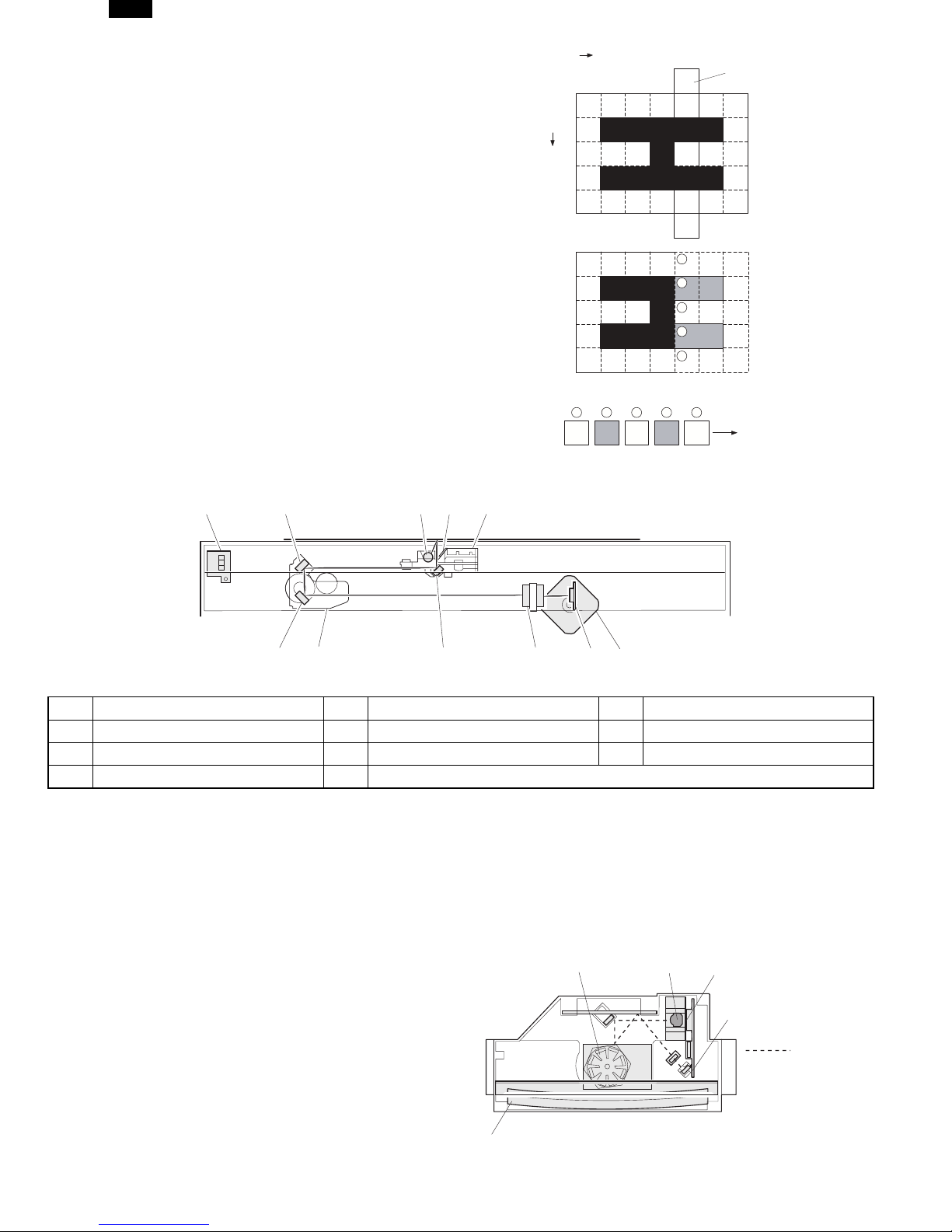
A.How to scan documents
The scanner has sensors that are arranged in a line. These sensors scan a
certain area of a document at a time and deliver outputs sequentially. When
the line is finished, the next line is scanned, and this procedure is repeated.
The figure below shows the case where the latter two sections of an image
which are scanned are shown with solid lines and the former two sections
which are being transmitted are shown with dotted lines.
The direction of this line is called “main scanning direction,” and the scanning
direction “sub scanning direction.”
In the figure above, one line is divided into 4 sections. Actually, however, one
line is divided into thousands of sections. For scanning, the light receiving element called CCD is used.
The basic resolution indicates the scanner capacity. The basic resolution is expressed in dpi (dot/inch) which shows the number of light emitting elements per
inch on the document.
The basic resolution of this machine is 400dpi.
In the sub scanning direction, at the same time, the motor that drives the optical system is controlled to scan the image at the basic resolution.
Sub scanning direction
Sensor scanning area
Main
scanning
direction
Original
1
2
3
4
5
Image data sent to the ICU PWB
5 4 3 2
1
To MCU PWB
B.Basic structure of scanner section
(1)
(11)
(4)
(7)
1Copy lamp (Xenon lamp)2Reflector (light conversion plate)3No. 1 mirror
4No. 2 mirror5No. 3 mirror6Lens
7No. 2/3 mirror unit8Copy lamp unit9CCD
10Mirror motor11MHPS (Mirror home position sensor)
The scanner unit performs scanning in the digital optical system.
The light from the light source (Xenon lamp) is reflected by a document and passed through three mirrors and reduction lenses to the CCD element
(image sensor) where images are formed. This system is known as the reduction image sensor system. Photo energy on the CCD element is converted into electrical signals (analog signals). (Photo-electric conversion). The output signals (analog signals) are converted into digital signals (A/D
conversion) and passed to the MCU (main control/image process section). The resolution at that time is 400dpi.
The mirror unit in the scanner section is driven by the mirror motor.
The MHPS is provided to detect the home position of the copy lamp unit.
(2)
(3)
(8)
(6)(5)
(9)
(10)
3.Laser unit
The image data sent from the MCU (image process circuit) is sent to
the LSU (laser unit), where it is converted into laser beams.
A.Basic structure
The LSU unit is the writing section of the digital optical system.
The semiconductor laser is used as the light source, and images are
formed on the OPC drum by the polygon mirror and fθ lens, etc.
The laser beams are passed through the collimator lens, the cylindrical
lens, the polygon mirror, the fθ lens, and the mirror to form images on
the OPC drum in the main scanning direction. The laser emitting PWB
is provided with the APC (auto power control) in order to eliminate fluctuations in the laser power. The BF PWB works for measurement of the
laser writing start point.
7 – 2
(3)
(5)
(1)(2)
(4)
: Laser beam
path for BF PWB
DP1200/1500
No.ComponentFunction
(1)Semiconductor laserGenerates laser beams.
(2)Collimator lens
Polygon mirror,
(3)
polygon motor
BD (Mirror, lens,
(4)
PWB)
(5)fθ lens
Makes the laser scanning speeds at both ends of the drum same as
each other.
a ≠ b ≠ c
abc
Converges laser beams in
parallel.
Reflects laser beams at a
constant rpm.
Detects start timing of laser
scanning.
Converges laser beams at a
spot on the drum.
Makes the laser scanning
speeds at both ends of the
drum same as each other.
(Refer to the figure below.)
d = e = f
def
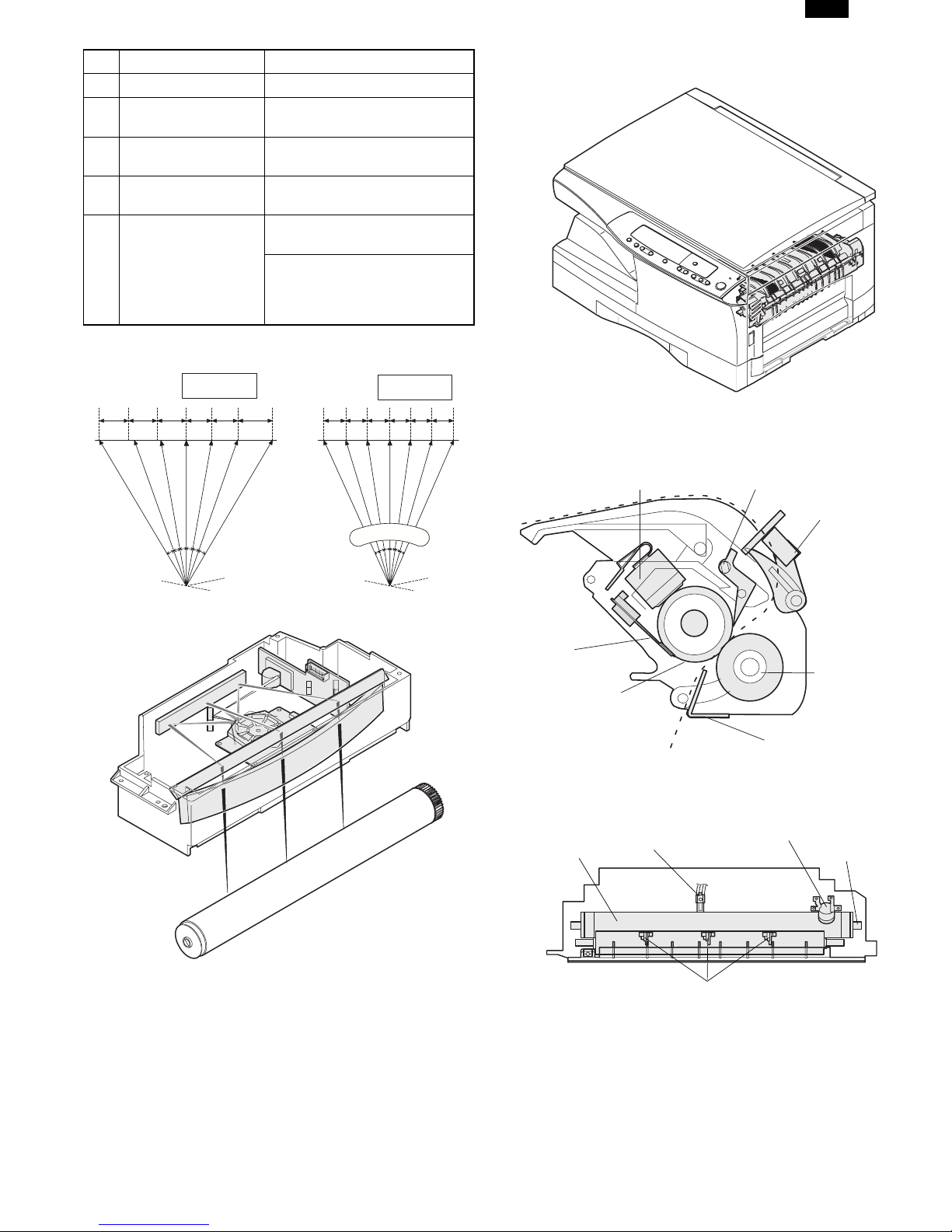
4.Fuser section
A.General description
General block diagram (cross section)
Thermal fuse
Separator pawl
PPD2
f
θ
LENS
B.Laser beam path
C.Composition
Effective scanning width:216mm (max.)
Resolution:600dpi
Beam diameter:75um in the main scanning
direction, 80um in the sub scanning
direction
Image surface power:
Polygon motor section:
0.20 ±0.03mW (Laser wavelength
780 – 795nm)
Brushless motor 20.787rpm
No. of mirror surfaces: 6 surfaces
Thermistor
Pressure roller
Heat roller
Paper guide
Top view
Heat roller
(1)Heat roller
A Teflon roller is used for the heat roller and a silicone rubber roller is
used for the lower heat roller for better toner fusing performance and
paper separation.
(2)Separator pawl
Three separator pawls are used on the upper heat roller. The separator
pawls are teflon coated to reduce friction with the roller and prevent a
smear on the paper caused by the separator pawl.
Thermistor
Separator pawl
Thermal fuse
Heater lamp
7 – 3
DP1200/1500
(3)Thermal control
1.The heater lamp, thermistor, main PWB, DC power supply PWB,
and triac within the power supply unit are used to control the
temperature in the fuser unit.
To prevent against abnormally high temperature in the fuser unit, a
thermal breaker and thermal fuse are used for safety purposes.
Heated by the heater
lamp.(950W)
Saftey device
(Thermal breaker, thermal
fuse)
Triac (in the
power supply unit)
The surface temperature
of the upper heat roller is
sensed by the thermistor.
Level of the thermistor is
controlled by the main PWB.
With the signal from the
main PWB, the triac is
controlled on and off.
(power supply PWB)
2.The surface temperature of the upper heat roller is set to 165˚C ∼
190˚C. The surface temperature during the power save mode is set
to 100˚C.
3.The self-check function comes active when one of the following
malfunctions occurs, and an "H" is displayed on the multicopy window.
a.When the heat roller surface temperature rises above 240˚C.
b.When the heat roller surface temperature drops below 100˚C
during the copy cycle.
c.Open thermistor
d.Open thermal fuse
e.When the heat roller temperature does not reach 190˚C within
27 second after supplying the power.
(4)Fusing resistor
Fusing resistor
This model is provided with a fusing resistor in the fusing section to improve transfer efficiency.
General descriptions are made in the following.
General descriptions
Since the upper heat roller is conductive when copy paper is highly
moist and the distance between the transfer unit and the fusing unit is
short, the transfer current leaks through the copy paper, the upper heat
roller and the discharging brush.
5.Paper feed section and paper transport section
A.Paper transport path and general operations
(2)
(1)
(1)Scanner unit(6)Main charger(11)Pickup roller
(2)Copy lamp(7)Heat roller(12)Manual paper feed tray
(3)Lens unit(8)Pressure roller(13)Manual paper feed roller
(4)LSU (Laser unit)(9)Drum(14)PS roller unit
(5)Paper exit roller(10)Transfer unit(15)Paper feed roller
Paper feed is made in two ways; the tray paper feed and the manual paper feed. The tray is of universal-type, and has the capacity of 250 sheets.
The front loading system allow you to install or remove the tray from the front cabinet.
The general descriptions on the tray paper feed and the manual paper feed are given below.
(5)
(3)
(4)
(6)
(15)
(13)
(14)
(7)
(8)
(9)
(10)
(11)
(12)
7 – 4
DP1200/1500
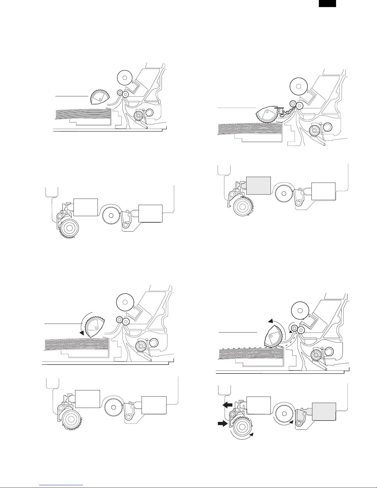
(1)Cassette paper feed operation
1)The figure below shows the positions of the pick-up roller, the paper
feed clutch sleeve, and the paper feed latch in the initial state
without pressing the COPY button after lighting the ready lamp.
The paper feed latch is in contact with the projection of the clutch
sleeve.
2)When the COPY button is pressed, the main drive motor starts
rotating to drive each drive gear.
The pick-up drive gear also is driven at that time. Since, however,
the paper feed latch is in contact with the projection of the clutch
sleeve, rotation of the drive gear is not transmitted to the pick-up
roller, which does not rotate.
PFS
RRS
OFF
OFF
5)At this time, the paper is fed past the paper entry detection switch
(PPD1), and detected by it. After about 0.15 sec from detection of
paper by PPD1, the tray paper feed solenoid (PFS) turns on so that
the clutch sleeve projection comes into contact with the paper feed
latch to stop the pick-up roller. Then the pick-up roller rotates for
about 0.15 sec so that the lead edge of the paper is evenly pressed
on the resist roller, preventing against skew feeding.
PFS
RRS
ON
OFF
3)After about 0.1 sec from when the main motor start rotating, the
tray paper feed solenoid (PFS) turns on momentarily.
This disengages the paper feed latch from the projection of the
clutch sleeve, transmitting rotation of the pick-up drive gear to the
paper feed roller shaft, rotating the pick-up roller to feed the paper.
PFS
RRS
OFF
OFF
6)To release the resist roller, the tray paper feed solenoid and the
resist solenoid are turned on by the paper start signal to disengage
the resist start latch from the clutch sleeve projection, transmitting
rotation of the resist drive gear to the resist roller shaft. Thus the
paper is transported by the resist roller.
7)After the resist roller starts rotating, the paper is passed through the
pre-transfer guide to the transfer section. Images are transferred on
the paper, which is separated from the OPC drum by the drum
curve and the separation section.
PFS
RRS
OFF
ON
4)After more than half rotation of the pick-up roller, the paper feed
latch is brought in contact with the projection of the clutch sleeve,
stopping rotation of the pick-up roller.
8)The paper separated from the drum is passed through the fusing
paper guide, the heat roller (fusing section), POD (paper out detector) to the copy tray.
7 – 5
 Loading...