

Page 1

1
User manual
Toshiba heat pump control by mobile phone
Page 2

Quick start guide
Suitable for everybody!
Page 3

Contents
Quick start guide
Suitable for everybody!
What Combi Control does? 6
Indicator lights 8
Buttons 10
Power 12
SIM card 12
Installing Combi Control 14
Testing Combi Control 19
Turning heat pump ON/OFF 20
Commands 22
User levels 24
Owner setup 26
Owner number reset 27
Contents
Advanced guide
For the brave!
Setup reset 30
User setup 31
Multiple commands 32
Heat pump model setup 34
Alarm messages 36
Error messages 39
Report messages 40
Combi Control command sheets 44
Get in touch with us 46
Page 4

6
What Combi
Control does?
Combi Control is a heat pump controller you operate
with a mobile phone. It is compatible with most
popular Toshiba heat pumps and all mobile phones (see
CombiControl.eu for the complete list).
The easiest way to use Combi Control is with a
Smartphone, using the Combi Control app downloadable
from the Android Market (for Android phones ) or App
Store (for iPhone). It can also be controlled with regular
mobile phone text messages (SMS). Combi Control allows
you to have long distance control over the mode of the
pump, room temperature and fan speed settings. Combi
Control can also inform you about low room temperature,
power failures and heat pump service intervals.
Page 5

8
Indicator lights
The controller has 3 LED indicators and 2 buttons for
easy setup. It has also 2 infrared LEDs that transmit your
commands to the heat pump.
LED 1 - Power
on switched on
blinking no power, working on battery
off switched o
LED 2 - mobile phone LED
on restart time, SIM missing or SMS processing
1 blink (3 s interval) normal status
3 blinks (3 s interval) no signal from mobile phone or not
connected to a mobile network
blinking (500 ms interval) data call session is active
LED 3 - IR LED
blinking transmitting by IR
LED 1 - Power
LED 2 - mobile phone LED
LED 3 - IR LED
Page 6

10
Buttons
Use a straightened paper clip or something similar to push
the recessed buttons.
RESET button
Short push turns the controller o when working on
battery
The controller has a battery that keeps it operational even
if it’s disconnected from a wall outlet. To fully turn o the
controller, push the RESET button. The 3 LED lights will
blink for about a second and the controller switches o.
Use this button also to clear the most recent settings (the
Owner number will remain unchanged).
TEST button
Short push turns the heat pump ON/OFF
Use the TEST button to conrm that the IR beam from the
controller reaches the heat pump.
RESET button
TEST button
IR beam
NB! Pushing both buttons simultaneously for 3 seconds initiates the hard reset: restores
factory settings, deletes Owner number and heat pump settings (same function as with
Page 7

12
Power
When the power is out (power = 0V) the controller
continues to work on the battery and turns o after the
battery’s voltage drops below 3.5V. A fresh battery lasts
for approximately 24 hours (note that over time the
battery’s capacity decreases). After the controller is turned
o the run time will be saved. To save battery life when
the power is out the controller can be turned o with a
short push on the RESET button.
SIM card
NB! Make sure you disable the PIN code of the SIM card
you use in Combi Control.
NB! Make sure the SIM card you use in Combi Control can
access 2G network. Combi Control is not compatible with
SIM cards that use only 3G network.
A) Make sure that you have previously disabled the SIM card PIN code.
Insert SIM card as shown into Combi Control.
B) Plug the adapter into the socket under the Combi Control.
Page 8
14
Installing
Combi Control
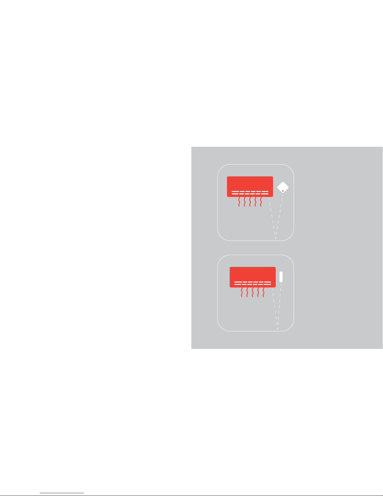
Combi Control should be mounted on the wall to the right
of your heat pump’s indoor unit (see g. 1), with its IR
transmitter pointing down. This way
the IR beam is reected from the oor and reaches the heat
pump’s sensor most eciently.
Other mounting congurations are possible too
as long as IR transmission from the controller
to the pump works.
NB! Thick carpets and dark oors can distort the IR beam.
Make sure the IR beam reaches the pump’s sensor by using
the controller’s Test function (see page 19).
Fig. 1
On the right side of
the indoor unit
Fig. 2
Attached to the right side of
the indoor unit
Page 9

Fig. 3
Beneath the indoor unit
Fig. 4
On the wall, opposite to
the indoor unit
Fig. 5
On a ledge, opposite to the
indoor unit
Page 10

19
Fig. 6, 7
Do not place Combi Control
on the left side of the indoor
unit!
Indoor unit’s internal
condenser might block Combi
Control’s signal.
Testing Combi
Control
To see if Combi Control can send commands to your
heat pump, turn o the pump and press the controller’s
TEST button. When the connection is established, Combi
Control turns the pump on with its last settings and you
can proceed using the controller.
Page 11

20
Turning heat
pump ON/OFF
SMS Command ON turns heat pump on.
SMS Command OFF turns heat pump o.
ON
sms: sms:
OFF
Page 12

22
Commands
The range of heat pump temperature values Combi
Control controls is 16-30 °C (default +20 °C) and the fan
speeds are MIN, NORM, MAX
(the default is NORM).
After selecting a mode (AUTO, DRY, COOL, HEAT, T8, T10)
heat pump is turned on with 20 °C maximum temperature
and normal fan speed, if not assigned dierently by the
Owner or the Users (see pages 24 and 29 for how to set
the Owner and Users).
The pump can be assigned dierent temperature and fan
speed values with Combi Control.
For example, the SMS: “COOL 19 MAX” orders the pump
to cool until 19 °C and fan at maximum speed. When
you change a heat pump function Combi Control always
responds with an SMS that reports its STATUS (see page 39
for full STATUS report explanation).
MIN
NORM
MAX
AUTO
DRY
COOL
HEAT
T8
T10
16
17
18
...
28
29
30
Combine the pump mode, room temperature and fan speed values for a home
atmosphere you like the best.
Page 13

24
User levels
The amount of control Combi Control users have over the
device and the amount of information they receive from
the device can be set on a 3 level scale:
1. The Owner can send commands, report queries, setup
commands and receive Combi Control report messages
and alarm messages.
2. The Users can send commands and report queries to
Combi Control but cannot send Setup commands.
3. The All-level users can make report queries about the
status of the controller.
Page 14

26 27
Owner setup
Setup can only be performed by the Owner. When no
Owner has been previously set, Owner number can be
sent from any mobile phone number. There are 2 ways
to do this:
The to-be Owner sends the SMS “93” to the controller. The
SMS containing “93” followed
by the mobile number of the to-be Owner –
e.g. “935012345”– is sent from any mobile phone.
The Owner number can be international (with the “+”
symbol and country code) or local. The length of the
number must be between 3 -16 symbols (“+” counts as
1 symbol).
Successful Owner number entry/Owner number change
is conrmed by “VERSION” report SMS sent to the new
Owner (see page 40 for full “VERSION” repor t explanation).
After Owner number has been set up, setup can be done
from this Owner number. All other numbers attempting
to change setup will be ignored. When no Owner number
has been entered all numbers have Owner rights (all
numbers can assign themselves as owners and no alarm
messages will be sent). When the Owner has not set User
numbers, all numbers have User rights.
Should you suspect Combi Control could be controlled
from unapproved numbers, we recommend you set the
Owner and User numbers.
Owner number
reset
Once set, Owner number can be reset via mobile phone
only by the Owner himself or by performing a hard reset
by pushing both controller hidden buttons simultaneously
for 3 seconds (hard reset can also be used when a wrong
Owner number is entered by mistake).
Page 15

28
Advanced setup
For the brave!
Page 16

30 31
Setup reset
For setup reset send the SMS “90” to the controller. Combi Control responds with SETUP
report:
“Owner: All; Users: All; Pump: All; Ring 2,2,2; Param: 5, 24, 180”.
This means Owner is not specied; all users can send commands;
the pump model is not specied, call commands are set to default;
“LOW TEMPERATURE” message will be sent when room temperature drops below 5 °C ,
“NO POWER” message blackout is in 24 hours and the “SERVICE” alarm message interval
is 180 days.
Setup SMS command you
send
Response SMS Controller function you activate
90 SETUP
Setup reset (Owner deleted)
and controller restart
User setup
To set User numbers start your command SMS with “91”, followed by the mobile phone
number of the User. For example: “91+495012345” or “915012345” to enter User1
number where “5012345” is the cell phone number of User1 and +49 is the country
code. User numbers (Owner, User1, User2) can be international (with the “+” symbol and
country code) or local. The length of the number must be between 3-16 symbols
(“+” counts as one symbol). Multiple commands can be combined into one SMS. When a
User has been set, Combi Control responds with a SETUP report message.
Setup SMS command you send Controller function you activate
91xx* User1 number entry (to delete: 910)
92xx* User2 number entry (to delete: 920)
93xx* Owner number entry (to delete: 930)
*xx marks the place of mobile phone number
Page 17

32 33
Multiple commands
If you want to set up several parameters with one SMS, separate commands with one of the
following:
space
comma “,”
semicolon “;”
For example, the SMS „91+ 49550111111 92+49550222222 9522 9720”
sets the User1 and User2 numbers, species the heat pump model as “Toshiba Daiseikai 5”,
and determines that NO POWER message will not be sent in case of a power failure.
When a command in the multi-setup is incorrect, the Owner will receive an error message.
All the correct commands that precede the error command in the multi-setup command
will be activated.
Multi-setup sender will always receive SETUP report SMS from Combi Control to conrm
that all commands arrived to the controller. There can be spaces before and after a
command but not inside a command as this will interfere with the code.
Heat pump model setup
The pump can be chosen on 3 levels of precision:
1. The precise name of the pump: the manufacturer and the model.
This is recommended for the most ecient operation.
2. Pump manufacturer.
If you only choose the pump manufacturer, functions T8 will not be checked and the
command will be sent even if the pump does not have
T8 mode. If the exact pump model is not listed on our webpage or in this manual,
Combi Control may or may not work with the heat pump, for which the Combi Control
manufacturer will not be held responsible.
3. All pump models.
If you choose All pump models (SMS: “950”), then all supported brands IR commands will
be sent to the pump, and Combi Control can be used without choosing the pump more
precisely.
Page 18

34 35
Setup SMS command
you send
Heat pump model and series T8*
950 All pump models T8
952 Toshiba T8
9521 Toshiba Daiseikai 3 T8
9522 Toshiba Daiseikai 5 T8
9523 Toshiba Daiseikai 6 T8
* T8 is a heat pump function that keeps the room temperature from dropping below
8 °C respectively.
Page 19

36 37
Alarm messages setup
The Owner can change the default values of the conditions on which alarm messages
are sent. For example, SMS “9713” lowers the room temperature value at which “LOW
TEMPERATURE” SMS is sent from the default 5 °C to 3 °C.
Setup SMS
command you
send
Response
SMS format
Combi Control function you activate Default
values
91xx* SETUP
temperature treshold for
„LOW TEMPERATURE” message
5 °C
92xx* SETUP
“NO POWER” message blackout
in hours
24 h
93xx* SETUP
“SERVICE” message interval
in days
180 days
* xx marks the place of the numeric value
When you set parameter 971 to 0, (e.g. you send a text message “9710”) then the
controller will not send you a “LOW TEMPERATURE” message.
When you set parameter 972 to 0, then “NO POWER” message will not be sent.
When you set parameter 973 to 0, then “SERVICE” message will not be sent.
Alarm messages
Alarm messages are only sent to the Owner.
Combi Control alarm SMS Alarm message meaning Message blackout/
alarm treshold
e.g. “LOW TEMPERATURE:
6 °C” (when the limit is 7 °C)
Room temperature is low 24h / +5 °C
NO POWER 220V power failure Default: 24h
e.g. ”SERVICE: 1 days” Service date Default: 180 days
VERSION New Owner
After setting a new
Owner or changing
Owner
The „LOW TEMPERATURE” parameters (971) can be between 0-16
The
“NO POWER” parameters (972) can be between 0-48
The
“SERVICE” parameters (973) can be between 0-360
Page 20

38 39
Error messages
“Error command: text”
SMS will be sent if there was an error in your command.
For example, an SMS “cool19max” receives the response
“Error command: cool19max”. Note that Combi Control will only return your incorrect
command without suggesting a correct one (the error in the example is the absence of
spaces between commands).
“Error userrights: text”
SMS will be sent if the user had no rights for that command.
“Error pump command: text“
SMS means the operation T8 is not available for the specied pump.
When Combi Control fails to send an SMS it will retry after 1 minute.
Page 21

40 41
Report messages
You can send report requests to Combi Control about your heat pump status, controller
status and the setup of the controller. Report messages are sent only to the sender of the
request.
SMS
command
you send
SMS command
function
Response SMS example
STATUS
Pump status
request
Pump: ON; Mode: HEAT; Fan: MAX;
VERSION
Controller
status request
Ver: 1.01b05; Pump: Toshiba, ON; Power: ON
(4.37V); Room: 19C; GSM: 14,1; Life: 00.05;
Owner: +49550111111;
SETUP Setup request
Owner: +49550111111; Users: All; Pump: Toshiba,
ON/OFF/NO POWER; Ring: 2,2,2; Param: 5,24,180;
Pump ”STATUS” report explanation
Pump “STATUS” report
SMS Format
Response SMS example
Pump: ON/OFF/NO POWER Pump ON/OFF/NO POWER
Mode: AUTO/DRY/COOL/HEAT/T8/T10 Pump mode
Fan: AUTO/MIN/NORM/MAX Fan speed
Temp: xxC Pump temperature
Room: xxC Room temperature
Page 22

42 43
Controller “VERSION” report explanation
SMS format Explanation
Ver: version number Combi Control firmware version
Pump: type,ON/OFF Pump status: type and ON/OFF
Power: ON/OFF(x.xxV)
Voltage 5V input and battery voltage
(3.50V- 4.20V)
Room: xxC Room temperature in Celsius degrees
GSM: sq, cell
GSM signal strength (0-31,99) and GSM
area info (1-local network, 5-roaming)
Life: mm.dd Controller run time: months, days
Owner: number Owner mobile phone number
”SETUP” report explanation
SMS format Explanation
Owner: number / All Owner number or All if not defined
Users: number1, number2 / All
User1 and User2 number or All if not
defined
Pump: pump manufacturer’s and
model name
Chosen pump model:
Toshiba
ALL
Ring: x,x1,x2 Ring codes: Owner, User1, User2
Param: x1,x2,x3
Parameters: 971 (low temperature),
972 (no power), 973 (service)
Page 23

44 45
Heat pump ON/OFF
Restart and Owner number entry
Command SMS Heat pump function
ON Pump ON
OFF Pump OFF
Command SMS Controller function
90
Setup reset (Owner deleted)
and controller restart
Commands
Command SMS Heat pump function
AUTO AUTO (+20 °C, fan: NORM)
DRY DRY (+20 °C, fan: NORM)
COOL COOL (+20 °C, fan: NORM)
HEAT HEAT (+20 °C, fan: NORM)
T8 T8 mode
Setup command SMS
you send
Heat pump model and series T8
950 All pump models T8
952 Toshiba T8
9521 Toshiba Daiseikai 3 T8
9522 Toshiba Daiseikai 5 T8
9523 Toshiba Daiseikai 6 T8
Heat pump model setup
Page 24

46
Get in touch with us
Page 25

 Loading...