

Page 1
TOSHIBA
Macintosh Ethernet and Wireless Network Configuration
The following screens describe how to configure the network set t ings for a Ma cint osh OS 9
computer.
Macintosh OS 9 Configuration Ethernet Settings
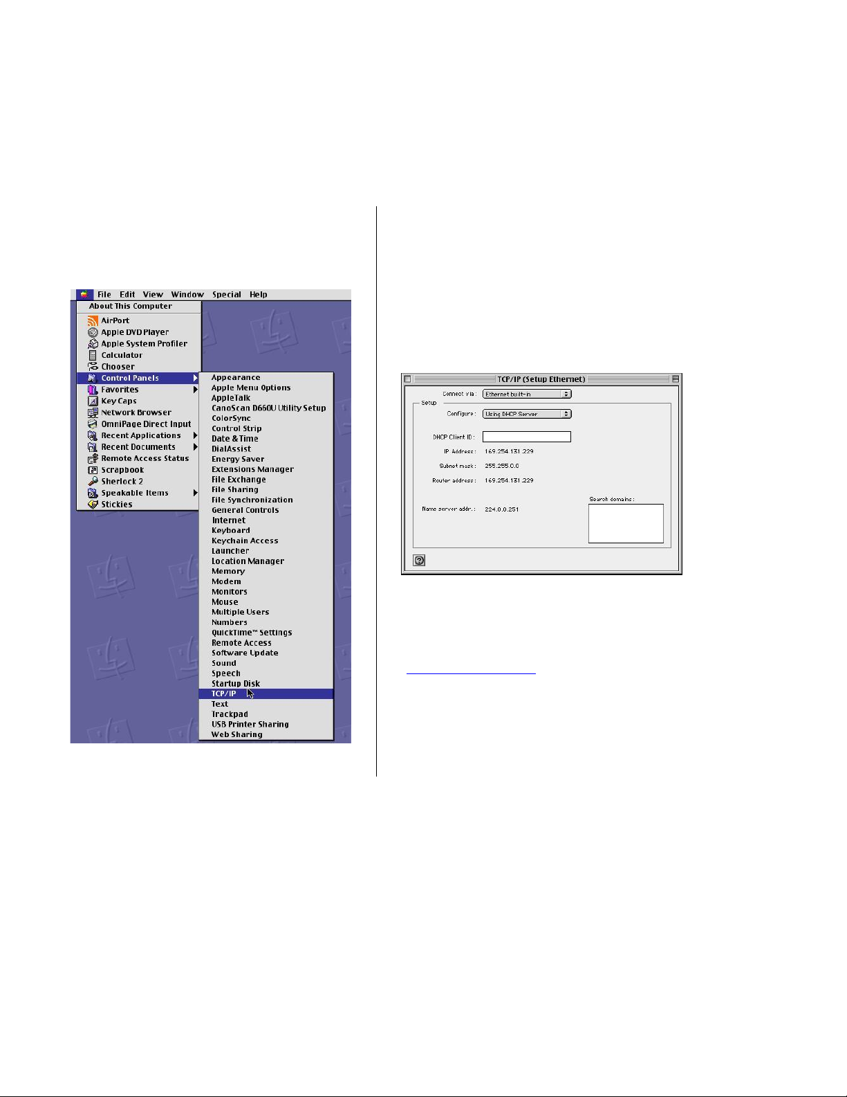
Step 1: At the Macintosh desktop, click the
Apple icon at the top left of the screen,
select Control Panel, and then click the
TCP/IP listing on the side panel.
Step 2: In the TCP/IP (Setup Ethernet)
panel, select the Ethernet port you are usin g
to connect your Macintosh to the PCX4500
in the Show choice box. The default port is
“Built–in Ethernet”. Then select “Using
DHCP Server” in the Configure choice box.
Close the panel by clicking on the top left
corner. You will be prompted to save the
configuration.
Step 3: You should now be able to access
the PCX4500 Configuration Pages.
Launch the browser supplied with the
Macintosh and open location:
”http://192.168.100.1
Proceed to the Configuring the PCX4500
section of this manual.
”
25
Page 2
TOSHIBA
Macintosh OS 9 AirPort Settings
If you are using the AirPort wireless connection, first verify the PCX4500 wireless link is turned on.
Refer to the “PCX4500 Wireless Configuration ” page in this manual.
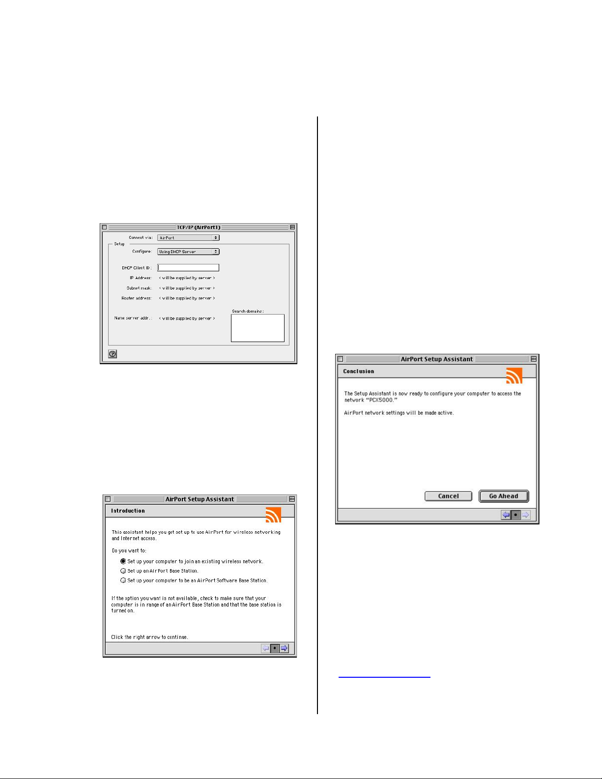
Step 1: Using the same procedure
described previously to set the Ethernet
TCP/IP configuration, navigate to the
TCP/IP (Setup Ethernet) panel and select
AirPort in the Connect via choice box.
Then select Using DHCP Server in the
Configure choice box. You will be
prompted to save the changes.
Step 2: At the Macintosh Desktop, double
click the Macintosh HD icon, and navigate
to the AirPort Setup Assistant icon located
in the Applications/ Uti litie s/Assist ants fold er.
Launch the “AirPort Setup Assistant”
application by double clicking the icon.
Select “Set up your computer to join an
existing AirPort network”. Click the right
arrow button to continue.
The Setup Assistant will scan for nearby
802.11b wireless base stations. If the
PCX4500 is in range, it will respond with a
message announcing it has joined the
network.
If the AirPort Assistant cannot find a
wireless network, verify the Macintosh is in
range of the PCX4500 and that the
PCX4500 has had the wireless option
turned on.
Step 3: If the AirPort Setup Assistant is
successful in finding the PCX4500 wireless
base station, it will display a panel stating,
“The AirPort Assistant is now ready to
configure your computer to access the
network “PCX4500”.” Click the Go Ahead
button to proceed.
Step 4: After several seconds, you will be
notified that the AirPort Assistant was
successful, and prompted to click the
Connect Now button. After clicking the
Connect Now button, your browser should
launch automatically.
Step 5: You should now be able to access
the Internet. You should immedi ately enab le
wireless encryption. With a 10/100 Ethernet
connection, open location:
“http://192.168.100.1”.
Proceed now to the “PCX4500 Wireless
Configuration” sect ion of this manual t o set
the wireless security options.
26
Page 3
TOSHIBA
Macintosh OS X Configuration Ethernet Settings
The following screen shots give an example of how to configur e the network settings for a Macintosh
OS X computer.
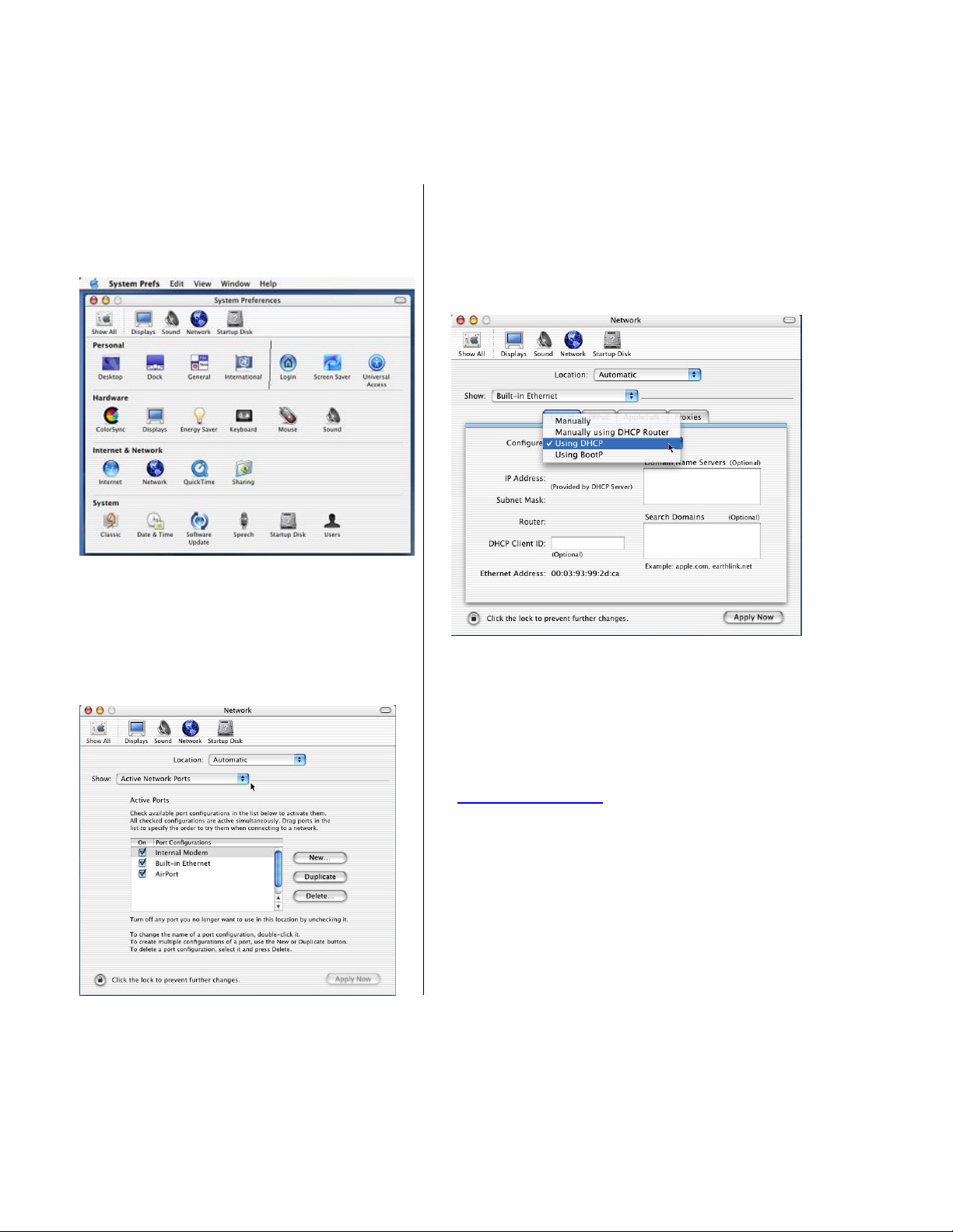
Step 1: At the Macintosh de sktop, select the
Apple icon at the top left of the screen, clic k
System Preferences, then select and click
the Network icon at t he t op of t he panel.
Step 3: Then select the Ethernet port you
are using to connect your Macintosh to the
PCX4500 in the Show choice box. The
default port is “Built–in Ethernet”. Click the
TCP/IP tab and select “Using DHCP” in the
Configure choice box.
Step 2: In the Network panel, Select
“Active Network Ports” in the Show choice
box to verify your networking interfaces
(Built-in Ethernet, Add-on Ethernet, or
AirPort) are active.
Step 4: Click the Apply Now button at the
bottom right corner of the menu.
Step 5: You should now be able to access
the PCX4500 configuration pages. Launch
the browser supplied with the Macintos h and
open location:
”http://192.168.100.1
“Configuring the PCX4500 Gateway”
section of this manual.
”. Proceed now to the
27
Page 4
TOSHIBA
Macintosh OS X AirPort Settings
If you are using the AirPort wireless connection, first verify the PCX4500 wireless link is turned on.
Refer to the “PCX4500 Wireless Configur ati on” page in this manual.
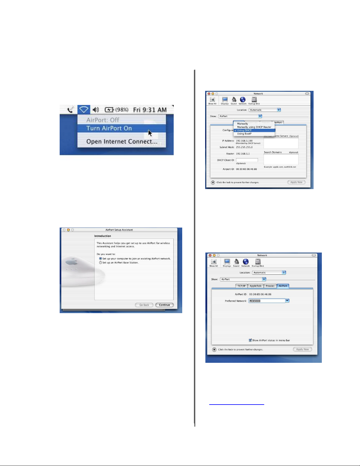
Step 1: In the Macintosh OS X toolbar (located
at the top of the desktop) select the AirPort
broadcast icon and choose “Turn AirPort
On”.
Then select “AirPort” in the Show choice box.
Select the TCP/IP tab and select “Using DHCP”
in the Configure choice box.
Step 2: At the Macintosh desktop, dou ble click
the Macintosh HD icon, and navigate to the
AirPort Setup Assistant icon located in the
“Applications/Utilities” folder. Launch the
“AirPort Setup Assistant” application by
double clicking the icon. Select “Set up your
computer to join an existing AirPort
network”. Click the Continue button.
The Setup Assistant will scan for nearby
802.11b wireless base stations. If the
PCX4500 is in range, it will respond with a
message announcing it has joined the
network.
If the AirPort Assistant cannot find a wireless
network, verify the Macint osh is in range of the
PCX4500 and that the PCX4500 has had the
wireless option turned on (see PCX4500
Wireless Configuration).
Step 3: At the Macintosh desktop, select the
Apple icon at the top right of the screen, click
System Preferences, and select and click the
Network icon at the top of the panel.
Step 4: While in the N etw ork Pa nel, select the
“AirPort” tab. Verify the Wireless Network
Name of the PCX4500 (default i s “PCX4500”)
in the “Preferred Network:” text entry box.
The PCX4500 should be listed as one of the
available networks recognized by the AirPort
card.
Step 5: You sho ul d now be able to access the
Internet. You should immediately enable
wireless encryption. With a 10/100 Ethernet
connection, open location:
“http://192.168.100.1”. Proceed now to the
“PCX4500 Wireless Configuration” section
of this manual to set the wireless security
options.
28
Page 5

TOSHIBA
Configuring the PCX4500 Gate way
The following sectio ns describe how to config ure the netw ork and security settings for the PCX4500.
You should be able to access these settings once you have completed the Ethernet or USB
installation for your computer. In most cases, you will not need to change the default settings of the
PCX4500.
If you plan to use the wireless access capability of the PCX4500, please review the “PCX4500
Wireless Configuration” section to set your security parameters. The default settings do not
protect your home network from an attack by an unauthorized wireless us er.
The PCX4500 contains an embedded Web server that allows you to change its configuration. The
PCX4500 configuration web pages may be accessed through any Internet browser such as
Microsoft Internet Explorer (5.0 or later recommended).
These web pages are passw ord prot ect ed t o prevent unauthorized chan ges.
The PCX4500 configuration options are availa bl e in these web page locati ons:
Configuration O pt ion:
Turn the firewall On/Off (default: On) see Security
Setup access rules Security -> Access Control
Setup DMZ (Demilitarized Zone) Security -> DMZ host
Setup host name Advanced -> System Settings
Setup fixed IP addresses for modem, PC’s
Change modem’s DHCP server settings Advanced -> DHCP Server
Change modem’s password Advanced -> Users Settings
Upgrade firewall security
Enable wireless encryption
You may also check the PC X4500 status:
View firewall report see Security -> Firewall Log
View system log report System Monitoring -> Sys t em Lo g
View traffic statistics System Monitoring -> Traffic
PCX4500 Web-based Management page loc at ion:
29
Page 6
TOSHIBA
Accessing Web-based Management
To access the management console:
Note: If your computer is running an operati ng sy stem that supports U PnP, such as Windows Me or
Windows XP, you can easily add the computer to your home network and access the Management
Console directly from within Windows. See Pxx for information about connecting UPnP-enabled
computers.
1. Launch a Web-browser on a PC in the LAN.
2. Type 'http://192.168.100.1 ',or 'http://mypox' in the ad dress bar (Internet Explorer) or location b ar
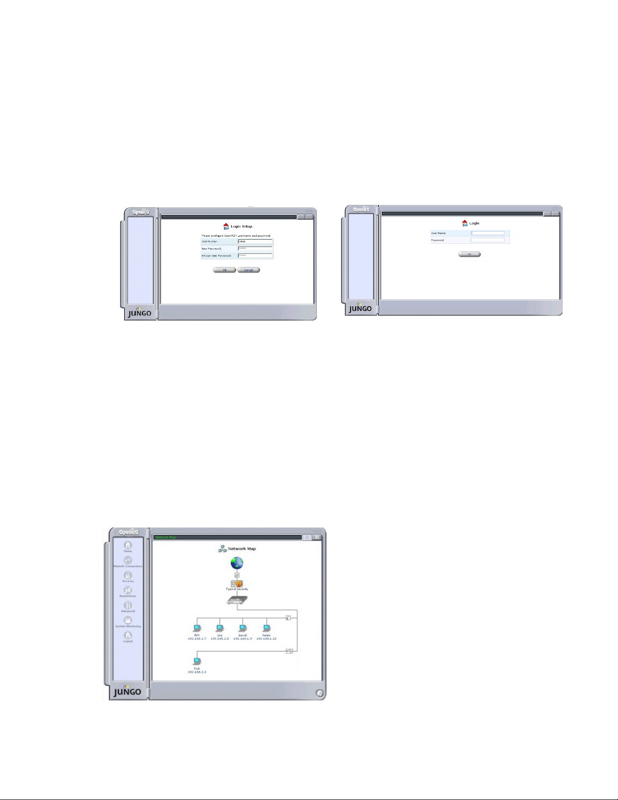
(Netscape Navigator). The
Figure 14: Login Setup Figure15: Login
Login
screen will appear.
3. Enter your username and passwor d t o log on to the web-based management.
Note: for security reasons, you should change these settings after the initial login. See Pxx for
details.
Note: Your session w i ll automatically finish after a fe w minut e s of in act ivity. If you try to operate
the management console after t he session has expired the Login screen will appear and you will
have to reenter your user na me and password before proceeding. This feature helps to prevent
unauthorized users from accessing the web-based management and changing the gateway's
settings.
The Network Map screen will appear.
Your Home Network Map
When you log into the management console you will see the Network Map scr een.
Figure 16: Network Map
30
Page 7
TOSHIBA
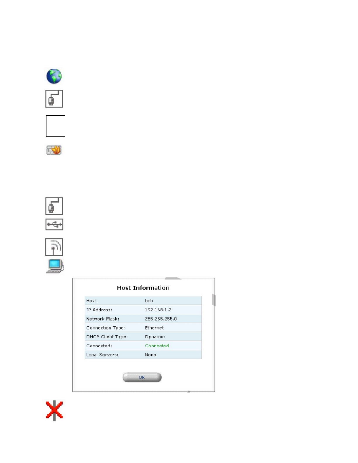
The network map depicts each of the computers in your home network, PCX4 500, t he F irew al l
(inside the Gateway) and the external net work (Internet ). The following t able explain s the meaning o f
each part of the network map:
Represents the Internet
Represents your WAN (Wide Area Network) connection - your connection to the
Internet - when using an Ethernet Gateway. Click this icon to configure the WAN
interface (see P35).
Represents your WAN(Wide Area Network) connections - your connection to the
Internet - when using a Wireless Interface. Click this icon to configure the
WAN interface (see P41).
Represents the firewall built into PCX4500. The height of the wall corresponds to
the security level currently selected: Minimum, Typical or Maximum. Click this
icon to configure security settings (see P44).
If PCX4500 is equipped w ith multip le LAN devic es then the home networ k will be show n sub-divided
into sub-networks (or subnets) and you will be able to see which computers are part of each
sub-network. Click the icon listed below that represents the subnet you wish to conf igure.
Represents your Ether net L AN (Loc a l Are a Net w ork) connection. Click this ic on
to configure network parameters for the Ethernet LAN device (see P38).
Represents your USB LAN connection. Click this icon to configure network
parameters for the USB LAN device.
Represents your W ireless LAN connecti on. Click this icon to c onfigure networ k
parameters for the Wireless LAN device.
Represents a computer (host) connected in the home network. Click this icon to
view network information for the corresponding computer (see figure 17).
Figure 17: Host Information
Represents a computer ( ho st) that is d isab led or t emporarily disconnected f rom
the home network.
31
Page 8
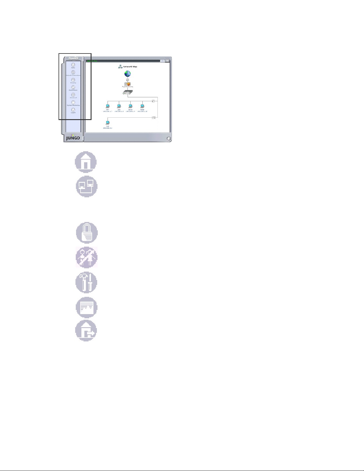
Left Sidebar
TOSHIBA
The web-based management screens have been
grouped into several subject areas and may be accessed
by clicking on the appropriate icon in t he left sidebar. The
subject areas are:
Figure 18: Left Sidebar
Home: Return to the Network Map
Network Connections: Create networks connections (see P35 or P38)
Wireless Connection: Configure the Wireless interface (see P41)
Security: Configure the firewall and regulate communications between the
Internet and the home network (see P44)
Restriction: Block access to specific Internet web sites (see P56)
Advanced: Control network parameters (DHCP server, DNS) and perform
administrative functions, including changing password and setting date & time
(see P58)
System Monitoring: View network status, traffic statistics and the system log
(see P71)
Logout: Log out from PCX4500
32
Page 9
TOSHIBA
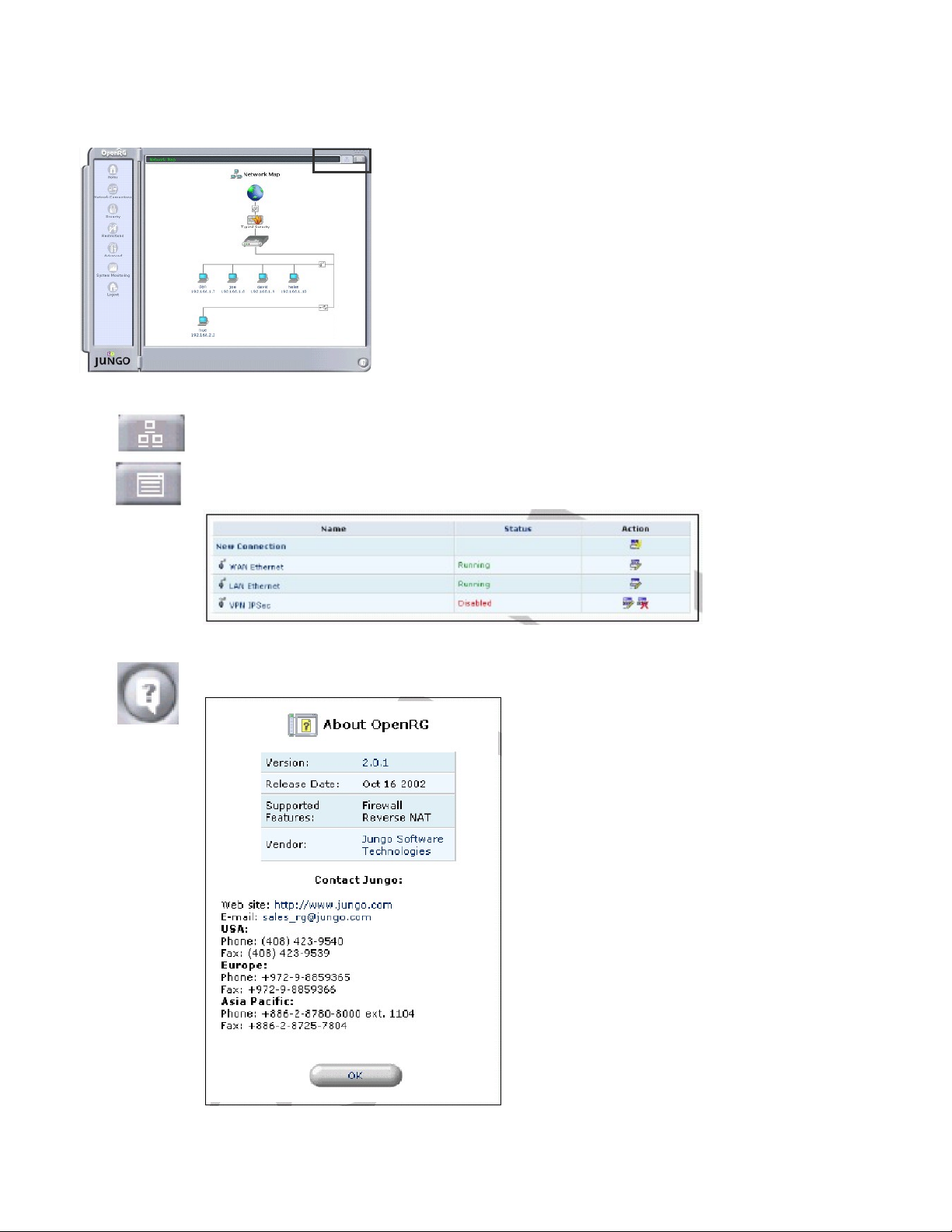
Navigational Aids
The black navigator bar, located at the top of the
management console, provides an easy way to locate
the current screen in the hierarchy of web-based
management screens. You may use it to quic kly return to
a screen that is above the current screen.
The icons listed below make it easy to quickly jump to key
information about y our home network. They are located
on the right side of the management console.
Figure 19: Host Information
Return to the Network Map screen
View a list of computers in the home network and the connection status of
each. Also listed is the status of the Internet connection and the LAN
connection.
Figure 20: Network Connection
View technical information about the system that you are running, including
version number and contact information.
Figure 21: Host Information
33
Page 10
TOSHIBA
Note: The manage ment screens depicted in this ma nual may differ somewhat from the
screens visible in your Management C onsole. This is primarily due to hardware differences
between the various platforms for which PCX4500 is available.
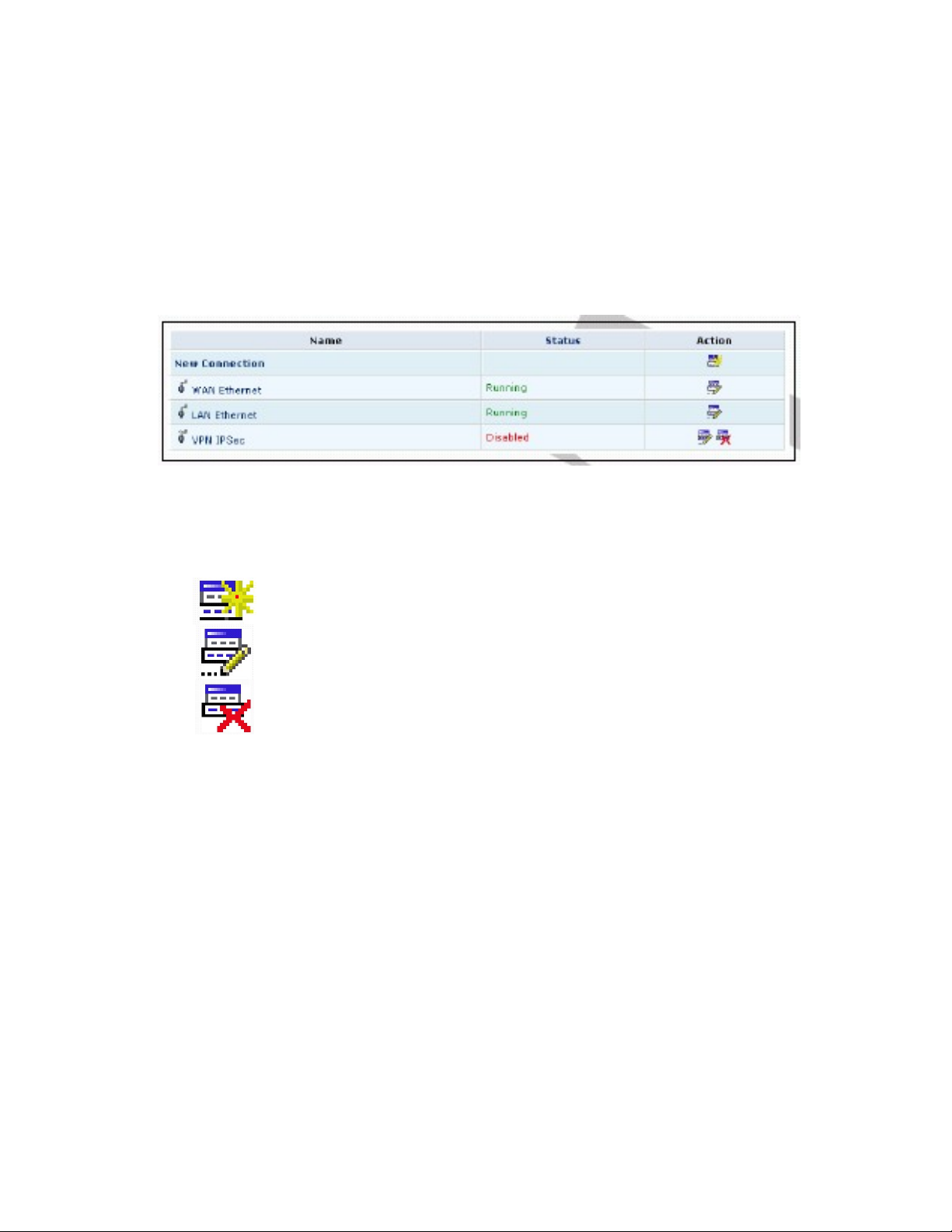
Managing Lists
Lists are structures used throughout the web-bas ed manag e ment. Lists hand le user define d entries
relating to elements such as network connections, local servers, restrictions and more. The
principles outlined in this section apply t o all list structures in the web-based management.
Figure 22: Typical Li st Structure
Figure 22 illustrates a typical list structure. Each row defines an entry in the list. The following button s
located in the 'Action ' column enable adding, ed it ing and deleting list entries:
Use the Add button to add an item to the list. Fill in the list entry’s fields, and
click the OK button to add the entry to the list.
Use the Edit button to edit an item from the list.
Use the Delete button to remove an item from the list.
34
Page 11

TOSHIBA
PCX4500 WAN Device Configuration
Click the Network Connections icon on the left side of the PCX4500 Web-based Management
screen to display the Network Con nect ions scree n (see f igure 23).
Figure 23: Network Co nnections
In the Network Connections screen, click WAN Side. The displayed screen allows you to set
connection parameters and configure the appropriate protocol to be used for the WAN connection,
according to the informat i on provided by your service prov ider.
You can also use the Net work Connect ion s screen to mon itor connection status.
Note: Some of the changes require knowledge of network communication protocols. Making
changes without understanding the expected results could cause communication problems within
your network.
35
Page 12

TOSHIBA
Configuring the WAN Ethernet Device
1. In the
column for “WAN Side ” (see figure 23).
The
Figure 24: Network Connection WA N Si de
2. The most recent network configuration for the WAN Ethernet Device is displayed. Click the
Settings button to change the settings; the Configure WAN Ethernet cbl0 screen will appear
(see figure 25).
Network Connection
Network Connection W AN Side
screen, click the WAN S id e , or click the Edit button in the "Action"
screen will appear (see figure 24).
Figure 25: Configure WAN Side
36
Page 13

TOSHIBA
3. Under “Internet Protocol”, select one of the following three methods to specify the desired
address.
- No IP Address: IP address is not specified at the WAN side. In this case, the system does
not operate as a NAT.
- Obtain an IP Address Automatically: The IP address is automatically obt ained from the
network side DHCP server (Factory default).
* Override Subnet Mask: Select t he check box and enter the value to man ually specify an
address without using the subn et ma sk obtained from the DHCP server.
- Use The Following IP Address: Enter value s in t he “IP Address”, ”Subnet Mask ”
and ”Default Gateway” fields.
4. Under “DNS Server”, select one of the following two methods to specify a DNS server.
- Obtain DNS Server Address Automat ically: The DNS server address is automatically
obtained from the DHCP server.
- Use The Following DNS S erver Address: Enter values in the “Pri mary D NS Server”
and ”Secondary DNS Server” fields.
5. Under “Routing”, select one of the following two methods t o specify the routing method.
-
Basic: Factory default
- Advanced: Choose a routing mod e in t he “Routing Mode”, and enter values in the “ Device
Metric”. If you use the default route, check the box next to the “Default R out e”.
6. Click the OK button to save your changes.
37
Page 14

TOSHIBA
PCX4500 LAN Device Configuration
Click the Network Connections icon on the left side of the PCX4500 Web-based Management
screen to display the Network Connections screen (see figure 26).
Figure 26:Network C onnections
Network Connections
In the
modify the Local IP Address and/or S ubnet Mask for the PCX4500' s LAN device.
You can also use the Network Connections screen to monitor connect ion st atus.
Note: Some of the changes require knowledge of network communication protocols. Making
changes without understanding the expected results could cause communication problems within
your network. If something goes w rong you can a lways restore the PCX45 00 factory default settings.
Keep in mind, though, that y ou must be able to access the PCX 4500 Web-bas ed Manage ment area
in order to do so.
screen, click LAN Ethernet lan0. The displayed screen allows you to
38
Page 15

TOSHIBA
Configuring the LAN Device
1. In the
Figure 27: Network Connection LAN Ether net lan0
2. The most recent network configuration for the LAN Ethernet Device is displayed. Click the
Network Connection
"Action" column for “LAN Ethern et lan0” (see figure 26).
Network Connection LAN Ethernet lan0
The
settings button to change the settings; the Configur e LAN Ether net lan0 scree n will appe ar (see
figure 28).
screen, click the LAN Ethernet lan0, or click the Edit button in the
screen will appear (see figure 27).
Figure 28: Config ure LAN Ethernet lan0
39
Page 16

TOSHIBA
3. Under "Internet Protocol", to specify the IP address, enter value in the “IP Address”, ”Subnet
Mask” and ”Default Gateway” fields.
4. Under “DNS Server”, select one of the following methods to specify t he D NS s erver .
- Obtain DNS Server Address Automat ically: The DNS server address is automatically
obtained from the DHCP server.
- Use The Following DNS S erver Address: Enter values in the “Pri mary D NS Server”
and ”Secondary DNS Server” fields.
5. Under “DHCP Server”, configure the desired DHCP settings.
- Enabled: Select this check box to use t he DHCP server.
- Start/End: Enter values in the ”Start” and ”End” fiel ds to specify the range of IP addresses
provided by the DHCP server.
Note: The DHCP server can provide a max imum of 253 addresse s, not includ ing LAN side
IP addresses. You can include LAN side IP addresses in the IP address range speci f ied
here.
-
Lease Time in Minutes: Enter the lease time (in minutes).
-
Provide host name if not specified by client: When y ou select this check box, PCX4500
defines the host name when the host name cannot be obtaine d.
6. Configure "Additional IP Address" as needed.
7. Click the OK button to save your changes.
40
Page 17

TOSHIBA
PCX4500 Wireless Configuration
You can use the Wireless Settings screen to set parameters related to the PCX4500 wireless
interface.Clic k the Wireless icon on the left side of the PCX450 0 Web-base d Managem ent screen to
display the Wireless Sett i ngs scre en (see figure 29).
Figure 29: Wireless Setti ngs
You use this screen to select the wireless interface you want to use and to set the SSID.
Configuring the Wireless Interface setting
1. Click the Wireless button on the
configures wireless interface setting will appear (see figure 30).
Wireless Settings
screen. The
Wireless Settings
screen that
Figure 30: Wireless Setti ngs Screen – Configurin g the wireless interface
41
Page 18

TOSHIBA
2. Complete the followi ng t he fields:
- Wireless: Select "Enabled " or "Disabled" for the Access Point. Th e fa ct ory default is
"Enabled".
- SSID: Enter text for SSID Access Point within 31 characters. The factory default is
"PCX4500".
-
Channel: From 1 to 11, select a channel to be us ed for co mmuni catio n betw ee n the A cces s
Point and wireless station. The factory default is “1 0“.
3. Click the OK button to save your changes.
Configuring the WEP setting
1. Click the WEP button on the Wireless Settings screen. The Wireless Encryption screen that
configures a WEP (wireless encry pt ion and authentication) w ill appear (see figure 31).
Figure 31: Wireless Encryption Screen
2. Complete the followi ng t he fields:
-
WEP: Select "Enabled" or "Disabled" for WEP. The factory default is "Disabled " .
-
Transmit Key: Select WEP Key1 t o Key4 that will be used for trans mission.
-
Bit: Select 64, 128, or 256 for the WEP key length.
- Type: Select Hex or ASCII for the data entry format of the WEP key.
-
Value: Enter the valu e of the WEP key.
3. Click the OK button to save your changes.
42
Page 19

TOSHIBA
Configuring the Station Filter setting
1. Click the Filter button on the
wireless interface will appear (see fig ure 32).
Figure 32: Station Filter
2. In the Station Filter field, sele ct "Enable d" or "Disabl ed" for station f iltering. The factory defau lt is
"Enabled".
Wireless Settings
screen.The
Station Filter
screen that configures a
3. The MAC address of the wireless terminal that is accessing the network is automatically
registered in the "MAC address" field. In default status, access by the terminal is not allowed.
However, if there is no other "Allowed" terminal, access by this terminal is temporarily allowed
when "T e mporary Allowed" stat us is in effect. When even one termina l is registered as "Allowed",
other "Temporary Allowed" terminals change to "Not Allow ed" st at us.
4. To manually register an address, enter the Mac addr ess subj ect t o filt ering i n the "Mac Address "
field and then click the Add button.The entered Mac address is added in the table under the
entry field with “Allowed” status.
Note: When you select the "Allow" check box, the registered Mac address be comes accessible. Until
the OK button is pressed, this setting is not effective in operation.
5. Click the OK button to save your changes.
43
Page 20

TOSHIBA
Security
PCX4500's Security Suite includes comprehensive, robust security services: Stateful inspection
Firewall, user authenticat i on protocols and password prot ect ion mechanisms. Thes e f eat ures taken
together allow users to connect their computers to the Internet and simultaneously be protected
from the security threats of the Internet.
PCX4500's Firewall (RG-FW
tailored to the needs of the residential user and has been pre-configured to provide optimum
security. In addition, the Firewall has many advanced features which allow you to further customize
it to your needs.
Using the management screens in the Security section, you can:
• Choose the Security Level for the Firewall (see P44)
• Set Access Controls to prohibit computers in the home network from accessing services on the
Internet (see P46)
• Configure the Local Servers av ailable in the home network (see P48)
• Designate a local computer as a DMZ Host so that network traffic associated with certain
Internet applications can b ypass the Firewall (see P52)
• Configure Remote Access to enable remote configuration of PCX4500 from any Internet
accessible computer (see P53)
TM
), the cornerstone of PCX4500' s security suite, has been exclusively
• View and configure the Firew all Log (see P54)
Security Level Setting
Use the Security screen to configure PCX4500 's basic security set t ings (see figure 33).
Figure 33: Security
The Firewall regulates the flow of data between the home netw ork and the Internet.
Both incoming and outgoing data are inspected and then accepted (allowed to pass through
PCX4500) or rejected (barred from passing through PCX4500) according to a flexible and
configurable set of rule s. These rules are designed to prevent unwanted intrusions from the outside
while allowing home users access to the Internet services t hat t hey require.
44
Page 21

TOSHIBA
The Firewall rules specify what types of services available on the Internet may be accessed from
the home network and w hat types of services av ailable in the home net work may be accessed from
the Internet. Each request for a servic e that the F irewall re ceiv es, w heth er origin ating in the Int er net
or from a computer in the home network, must be checked against the set of Firewall rules to
determine whether the request should be allowed to pass through the Firewall. If the request is
permitted to pass, then all subsequent data associated with this request (a "session”) will also be
allowed to pass, regardless of its d irecti on.
For example, when you point y our Web brow ser to a Web pag e on the I ntern et a request is s ent out
to the Internet for this page. When the request reaches PCX4500, the Firewall will identify the
request type and origin-HTTP and a specific PC in your home network, in this case. Unless you
have configured access control to block requests of this type from this computer, the Firewall will
allow this request to pass out onto the Internet (see Pxx for more on sett ing access contro ls). When
the Web page is returned from the Web server the Firewall will associate it with this session and
allow it to pass, regardless of whether HTTP access from the Internet to the home network is
blocked or permitted.
The important thing to note here is that it is the origin of the request, not subsequent responses to
this request, that determines whet her a session can be established or not.
You may choose from among three pre-defined security levels for PCX4500: Min i mu m, Typical (the
default setting) and Maximum. The table below summarizes the behavior of PCX4500 for each of
the three security levels. Note that the Access Control, Local Servers and Remote Access screens
may be used to further customize PCX 4500’s security settings.
• The Access Control screen can be used to further restrict access from the home network to the
Internet (see P46).
• The Local Servers screen can be used to enable access from the Internet to specified services
provided by computers in t he home network and special Internet applications (see P48).
• The Remote Access screen can be used to enable remote configuration of PCX4500 from any
Internet-accessible comput er (see P53).
Security
Level
Maximum
Typical
(Default)
Minimum
*These services include Telnet, FTP, HTTP, HTTPS, DNS, IMAP, POP3 and SMTP
Requests Originating in the WAN Requests Originating in the LAN
Blocked: No acce ss t o ho me ne two rk from
Internet, except as conf ig ured in the Local
Servers and Remote Access screens
Blocked: No acce ss t o ho me ne two rk from
Internet, except as conf ig ured in the Local
Servers and Remote Access screens
Unrestricted: Permits full access from
Internet to home network all connection
attempts permitted.
Limited: Only commonly-used services,
such as Web-browsing and e-mail, are
permitted*
Unrestricted: All services are permitted,
except as configured in the Access
Control screen
Unrestricted: All services are permitted,
except as configured in the Access
Control Screen
45
Page 22

TOSHIBA
• To co nfi gure PCX4500’ s security settings (see figure 34)
Figure 34: Security
1. Choose from among the three pre-defined security levels described in the table above.
T ypical Security is the default setting.
Note: Using the Minimum Security setting may expose the home network to significant
security risks, and thus should only be used, when necessary, for short periods time.
2. Check the Block IP Fragments box in order to protect your home network from a
common type of hacker attack that could make use of fragmented data packets to
sabotage your home network. Note that VPN over lPSec and some UDP-based services
make legitimate use of p fragments. You will need to allow IP fragments to pass into the
home network in order to make use of these select services.
3. Click the OK button to save your changes.
Adding Access Controls
You may want to block specific computers within the home network (or even the whole network)
from accessing certain services on the Internet. For example, you may want to prohibit one
computer from surfing the W eb, another computer from transferring files using FTP, and the whole
network from re ceiving inc o m ing e-mail.
Access Controls work by placing restrictions on the types of requests that requests pass from the
home network out to the Internet, and thus may block traffic flowing in both directions. In the e-mail
example given above, you may prevent computers in the home network from receiving incoming
e-mail by blocking their outgoing requests to POP3 servers on the Int ernet.
46
Page 23

TOSHIBA
Click the Access Control button in the Security screen to view a list of services that have been
restricted (see figure 34).
Figure 34: Access Control
• To ad d a new service or services to the Access Control table:
1. Click the New Entry button in the Access Control screen (see f igure 34). The Add Access
Control Rules screen will appear (see figure 35).
Figure 35: Add Access Control Rule
2. Select the service or services that you would like to bloc k.
3. Enter the local IP address of the computer that you would like t o block from accessing the
service (s). "0.0.0.0' will block all computers.
4. Click the OK button to save your changes and return t o the Access Co ntrol scr een.
Note: To block a service that is not included in the list, click the Add User Defined Service
button. The Edit Serv ice s creen w ill a ppe ar. Define the service, and click the OK button to save
your changes (see P51 for details). The service will then be automatically added to the Add
Access Control Rules screen. You may now select the service, just as you would a pre-defined
service.
You may change the computer (or computers) prohibited from accessing a particular service by
modifying the appropriat e ent ry in the Access Control table.
47
Page 24

• To mo di fy an entry in the Access Control table:
1. Click the Edit button for the service in the Acces s C ont rol screen (see figure 34). The Edit
Access Control Rule screen will appear (see figure 36).
TOSHIBA
Figure 36: Edit Access Control Rule
2. Enter the IP address of the computer that you would like to block from accessing the
service(s), or se l e ct ‘Block Entire L AN’ to block all LAN c omputers.
3. Click the OK button to save your changes and return t o the Access Co ntrol scr een.
You may disable an access control without remov ing the serv ice from the Access C ontrol ta ble. This
may be useful if you wish to make the service available only temporarily and expect that you will
want to reinstate the restriction in the future.
• To temp orari l y disable an access control:
1. Clear the check box next to the service name. The status for the service will change to
Disabled.
• To reinstate the restriction at a later time:
1. Select the check box to next to the service name. The status for the service will change to
Enabled.
• To remov e an access restriction from the Access Control table:
1. Click the Remove button for the service. The service will be removed from the Access
Control table.
Local Servers
In its default state, PCX4500 blocks all external users from connecting to or communicating with
your network. Therefore t he system is safe from hackers w ho may try to intrude on the network and
damage it. However, you may need to expose your network to the Internet in certain limited and
controlled ways in order to enable some applications to work from the LAN (game, voice and chat
applications, for exa mp le) and t o est ablish servers in the home networ k. P CX 4500 's Local Servers
feature supports both of these functi onalities.
The Local Servers screen in the Management Console provides a list of the most commonly used
applications that require special handling by PCX4500 -all you have to do is identify which of them
you want to use and the local I P address of the computer that will be using the service. For
example, if you wanted to use the Net2Phone voice application on one of your PCs, you would
simply select 'Net2Phone' from the list and enter the local IP address of that computer in the
right-hand column. All Net2Ph one-relate d data arriv ing at P CX4500 from the I nternet will h enceforth
be forwarded to the specified comput er.
48
Page 25

TOSHIBA
Similarly, if you want to grant Internet users access to servers inside your home network, you must
identify each service that you want to provide and the PC that will provide it. For example, if you
want to host a Web server inside the home network you must select 'HTTP - Web Server' from the
list and enter the local IP address of the computer that will host the Web server in the right-hand
column. Then when an Internet user points her browser to the external IP address of PCX4500 the
Gateway will forw ar d t he incoming http request to t he c omputer that is hosting the Web server.
Note that if an Internet application that you wish to use or a service that you wish to provide is not
already in the list, you can easily add it (see P51).
Note: Applicatio n Level Gateways (ALGs)
Some applications, such as FTP, TFTP, PPTP and H323, require the support of special
application-specific ALC (Application Level Gateway) modules in order to work inside the home
network. Data packets ass ociated w ith these appl ications cont ain infor mation th at allows t hem to be
routed correctly. An ALG is needed to handle these packets and ensure that they reach their
intended destinations. PCX4500 is equipped with a robust list of ALG modules in order to enable
maximum functionality in t he home network.
Click the Local Servers button in the Security screen to view the list of special services and local
servers that are currently enabled in t he home network (see figure 37).
Figure 37: Local Servers
• To ad d a new service to the list of active local servers:
1. Click the New En try button in the Local Servers screen (see figure 37). The Add Local
Servers screen will appear (see figure 38).
Figure 38: Add Local Servers
49
Page 26

TOSHIBA
2. Select the service that you would like to provide.
3. Enter the local IP address of the computer that will provide the service (the "server”). Note
that only one LAN computer can be assigned to provide a speci fic service or application.
4. Click the OK button to save your changes and return t o the Local Servers screen.
Note: To add a service that is not included in the list click the Add User Defined Service
button. The Edit Local Server screen will appear (see figure 39). Define the service and click
the OK button to save your changes (see P51 for detaila). The service will then be
automatically added to the Add Local Servers screen. You may now select the service, just as
you would a pre-defined serv ice.
• To edit an entry in the Local Servers table so that a service can be provided by a
different local computer:
1. Click the Edit button for the service in the Local Servers screen (see figure 37). The Edit
Local Server screen will appear (see figure 3 9).
Figure 39: Edit Local server
2. Enter the IP address of the computer that you would like to prov ide t hi s service.
3. Click the OK button to save your changes and return t o the Local Servers screen.
You may disable a service without removing the service from the Local Servers table. This may be
useful if you wish to make the service unavailable only temporarily and expect that you will want to
make it available again in the future.
• To temp orari l y disable an access control:
1. Clear the check box next to the service name.
• To reinstate the restriction at a later time:
1. Select the check box next to the service name.
• To remov e an access restriction from the Access Control table:
1. Click the Remove button for the service. The service will be removed from the Access
Control table.
Note: How many computers can use a service or play a game simultaneously? Well, the answer
may be a bit confusing. All the computers on the network can use a specific service as clients
simultaneously. Being a client means t hat t he co mpu ter w ithin t he n etwor k init i ates t he con necti on –
for example, opens an FTP connection with an FTP server on the Internet. But only one computer
can serve as a server , meaning respondi ng to requests from computers on the Internet. Assigning a
specific computer as a server is done in the Local Servers sectinon of Web-based man agement.
50
Page 27

TOSHIBA
User-defined Service
The tables that appear on the Add Access Control Rules and Add Local Servers screens are
pre-configured to include most of the services that users may wish to block or activate. Sometimes,
however, the need arises to add non a pre-defined service. PCX4500 provides the User-Defined
Services list (see figure 40) for this purpose. All of the services in this list also appear at the top of
the Add Access Control Rules and Add Local Servers screens. When a service is added to one list
it automatically appears in the others. In this way, user-defined services never need to be entered
twice.
Figure 40: User-Defined Services
• To ad d a new service to the list:
1. Click the New Entry button in the User-Defined Services screen (see figure 40). The Edit
Service screen will appear (see figure 41).
Figure 41: Add or Edit a User-defined Service
2. Enter a name for the service.
3. Choose a port type and enter a port range for this service to use as appropriate. Usually
this information is av ai lable as part of the documentation that accompanies the program.
4. If necessary, click the Add port range type button to enter a port range of another type
(UDP or TCP) for the same service.
5. Click the OK button to save your changes and return to the User-Defined Services screen.
Note: You have now completed defining this service, and may go to the Add Access Control
Rules or Add Local Se rvers screen to block or activate the service. Refer to P46 and P48 for
further instruction.
51
Page 28

TOSHIBA
• To modify a user-defined service already in the list:
1. Click the Edit button for the service in the User-Defined Services screen (see figure 40).
The Edit Servic e screen will appear (see figure 42).
Figure 42: Add or Edit a User-defined Service
2. Modify the service name or port information as necessary.
3. Click the OK button to save your changes and return to the User-Defined Serv ices screen
• To remove a service from the list:
1. Click the Remove button for the service in the User-Defined Services screen (see figure
40). The service will be removed fro m the l ist.
Designating a Demilitarzed (DMZ) Host
The DMZ Host feature allows one local computer to be exposed to the Internet. Designate a DMZ
host when:
• You wish to use a special-purpose Internet service, such as an on-line game or
video-conferencing program, that is not present in the Local Servers list and for which no port
range information is available.
• You are not concerned with security and wish to expose one computer to all services without
restriction
Warning: A DMZ host is not protected by the Firew a ll and may be v ulnerab le to att ack. Des ignat ing
a DMZ host may also put other computers in the home network at risk. W hen designating a DMZ
host, you must consider the security implications and protect it if necessary.
An incoming request for access to a service in the home network, such as a Web-server, is fielded
by PCX4500. PCX4500 will forward this request to the DMZ host (if one is designated) unless the
service is being provided by another PC in the home network (assigned in Local servers), in which
case that PC will receive t he request instead.
• To designate a local computer as a DMZ H ost:
1. Click the DMZ Host button in the Security screen. The DMZ Host screen will appear (see
figure 43).
Figure 43: DMZ Host
52
Page 29

TOSHIBA
2. Enter t he local IP ad dress of the comp uter that y ou would like to desi gnate as a DMZ host .
Note that only one LAN co mp ut er may be a DMZ host at any t ime.
3. Click the OK button to save your changes and ret urn to the DMZ Host screen.
You may disable the DMZ host so that it will not be fully exposed to the Internet, but keep its IP
address recorded on the DMZ Host screen. This may be useful if you wish to disable the DMZ host
but expect that you will w ant to enable it again in the future.
• To disable the DMZ host so that it will not be fully exposed to the Internet:
1. Clear the check-box next to the DMZ IP designation. The status of the DMZ host will
change to Disabled.
• To enable the DMZ host:
1. Select the check-box next to the DMZ IP designat ion.
Controlling Remote Access to PCX4500
It is possible to access and control PCX4500 not only from within the home network, but also from
the Internet. This allows you to view or change settings while traveling. It also enables your ISP to
change settings or help you troubleshoot functionality or communication issues from a remote
location.
Remote access to PCX4500 is blocked by default to ensure the security of your home network.
However, remote access is supported by the following services, and you may use the Remote
Access Configuration scre en t o selectively enable these services if they are needed.
Web-Management/HTTP
Used to obtain access to the Management Console and gain access to all system settings and
parameters.
Diagnostic Tools
Used for troubleshootin g and remote system management by your Internet Service Provider.
CAUTION: W eb-Management may be used to modify settings for or disable the Firewall. The user
may also change local IP addresses and other settings making it difficult or impossible to access
the gateway from the home network. Therefore, remote access to Telnet or HTTP services on
should be blocked and should only be permitted wh en absolutely necessary.
• To allow remote access to PCX4500 services:
1. Click the Remote Access button in the Security screen. The Remote Access Configuration
screen will appear (see figure 44).
Figure 44: Remote Access Configuration
53
Page 30

TOSHIBA
2. Select the services that you would like to make available to computers on the Internet.
These services include:
- Web-based Management - grants access to password-protected web-based
management. If a local server is configured to use port 80, select port 8080 to avoid
conflicts.
- Diagnostic tools - includes Ping and Trace route (over UDP). These services may be
used for troubleshooting and remote system management by the serv ice provider.
3. Click the OK button to save your changes and ret urn to the Security screen.
Firewall Log
The Firewall log displays a list of Firewall-related events, including attempts to establish inbound
and outbound connections, attempts to authenticate at an administrative interface (Web-based
Management), Firewall conf iguration and system start-up.
To view the Firewall Log, click the Firewall Log button in the Security screen. The Firewall Log
screen will appear (see figure 45).
Figure 45: Firewal l Log
The following are the event s and event-types that are automatically recorded in the Firewall l og:
1. Inbound/Outbound Traffic
• Connection accepted: access request complies with the Firewall's security policy.
• Accepted - Host probed*: this TCP connection request from a WAN host matches the
Firewall's security policy, but the WAN host is not recognized as trusted. The WAN host is
being challenged to verify t hat it is a trusted host.
• Accepted - Host trusted*: a reply from a previously challenged WAN host. This client
becomes a trusted host.
• Accepted - Internal traffic: all packets are allowed to move freely from one LAN host to
another
• Blocked - Policy violation: this access request v iolat es the Firewall's security poli c y
• Blocked - IP Fragment: if the Firewall is configured to block all IP fragments, this
message is recorded for every blocked fra gmented packet.
54
Page 31

TOSHIBA
• Blocked - IP Source-Routes: this message is recorded whenever a packet is blocked
due to a 'Source Route' (either st rict or loose) option set in its IP hea der
• Blocked - State-table error: the Firewall encountered an error during State-table lookup
or manipulation. Packet w as blocked.
2. Firewall Setup
• Aborting configuration
• Configuration complet ed
3. WBM Login
• Authentication Success
• Authentication Failure
4. System Up/Down
• The system is going DO WN for reboot
• The system is UP!
*Appears only with regard to inbound traffic.
You can choose additional activities to be recorded in the Firewall log using the Firewall Log
Settings screen (see figure 46). For each activity type you may choose to view messages
associated with successful attempt s (Accepted), failed attempts (Bloc ked) or bot h.
• To view/change the Firewall Log settings:
1. Click the Settings button that appears at the top of the Firewall Log screen. The Firewall
Log Settings screen will appear (see figure 46).
Figure 46: Firewall Log Settings
2. Select the types of activities for which you would l i ke to have a log message generated:
- Connection Attempts Message s -log a me ssage for each att empt to est ablish an inb ound
connection to the home network or vice versa.
- WBM Connection Attempts Messages -log a message for each attempt to browse to
Web-based Management from a browser outside the home network (included in first
category).
3. Select the Prevent Log Overrun checkbox in order to stop fogging Firewall activities
when the memory allocated for the l og f il ls u p
4. Click the OK button to save your changes and ret urn to the Firewall Log screen.
55
Page 32

TOSHIBA
Restriction
You may configure PCX4500 to block specific Internet Web sites so that they cannot be accessed
from computers in the home networ k.
Moreover, restrictions can be applied to a comprehensive automatically updated list of sites to
which access is not recommended.
• To view the list of Web sites currently being b locked, click the Restriction icon in the left sidebar.
The Restrictions screen will appear (see figure 47).
Figure 47: Restrictions
• To ad d a new Web site to the list:
1. Click the New Entry button in the Restinctions screen. The Restricted Web Site Address
screen will appear (see figure 48).
Figure 48: Restricted Web Site Address
2. Enter the web site address (IP or URL) that you would like to make inaccessible from your
home network (all web pages within the site will also be blocked). If the web site address
has multiple IP addresses, PCX4500 will resolve all additional addresses and automatically
add them to the restrictions list .
3. Click the OK button to add this site to the list. You will be returned to the previous screen
while PCX4500 attempts to find the site. "Resolving . . . " will appear in the Status column
while the site is being located (the URL is being 'resolved' into one or more IP addresses).
4. If the site is successfully located then 'Resolved' will appear in the status bar, otherwise
'Error' will appear. Click the Refresh button to update the status if necessary. In case
PCX4500 fails to locat e t he web site, do the following:
56
Page 33

TOSHIBA
- Use a Web browser to verify that the Web site is available. If it is then you probably
entered the Web site address incorrectly. Skip to "To modify a Web site address currently
in the list" below.
- If the Web site is not available then return to the Restrictions List at a later time and click
the Resolve Now button to verify that the Web site can be found and blocked by
PCX4500.
• To mo di fy a Web site address currently in the list:
1. Click the Edit button in the Restrictions screen. The Restrictions Web Site Address screen
will appear (see figure 49).
Figure 49: Restricted Web Site Address
2. Modify the Web site address as necessary. If it is long and /or complicated you may want to
use your browser's Copy and Paste functions to copy the address from the address bar to
the management console. Be sure to omit t he "http://" at the beginni ng and the "/" at the end
of the address.
3. Click the OK button to save your changes.
• To ensure that all current IP addresses corresponding to Web sites in the list are
blocked:
1. Click the Resolve Now button in the Restrictions screen. PCX4500 will check each of the
Web site address es in the list and e nsure that all IP addresse s at which t his Web sit e can be
found are included in the IP addresses column.
You may disable a restriction and make the Web site av ailable again without remov ing the site from
the Restrictions List. This may be useful if you wish to ma ke t he Web site available only temporarily
and expect that you will want to block it again in the future.
• To temp oraril y disable a restriction:
1. Clear the check box next to the restrict ed URL.
• To reinstate a restriction at a later time:
1. Select the check box next to the URL.
• To remove a restriction :
1. Click the Remove button. The restriction will be removed from the Restrict ions List.
57
 Loading...