

Page 1

D3003693D
B/W CCD Camera
CleverDragon series
CSCV90BC3
Operation Manual
Thank you for purchasing our B/W CCD camera. This operation manual co ntains many important information
such as how to use this product correctly and safely. Please read through this manual carefully. After r eading,
keep this manual by the side of this product for your future reference.
BEFORE USE - GENERAL SAFETY INSTRUCTIONS
Read the following safety precautions carefully before using this product. These instructions contain
valuabable infomation on safe and proper use that will prevent harm and damage to the operator and other
persons. Make sure that you fully understand the following details ( indications, graphic symbols) before
proceeding to the remaining sections in this manual.
OWNER’S RECORD
Please fill in the blank below the model name and product serial number, which is found on bottom chassis
of your device. Keep this number for your record.
Model Name
Serial No.
Indication definitions
Indication
Meaning
WARNING
This indicates the existence of a hazard that death or catastrophic bodily injury(*1)
may result from improper use.
CAUTION
This indicates the existence of a hazard that bodily injury (*2) or property damage(*3)
may result from improper use.
Notes
*1 Catastrophic bodily injury means loss of eyesight, burns ( high and low temperatured), shock, fracture,
poisoning, etc. which leaves a sequela and repuire hospitalization or prolonged treatment.
*2 Bodily injury means injuries, burns and electric shock which does not require hospitalization or
prolonged treatment.
*3 Property damage means extended harm to home, household effects, domesticated animals, and pets.
Graphic symbol definitions
Indication
Meaning
This mark indicates a prohibited action that must not be carried out. The actual prohibited
action is indicated in the symbol or nearby graphically or described in text.
This mark indicates a mandatory action that must not be carried out. The actual instruction is
indicated in the symbol or nearby graphically or described in text.
Handling Precautions
WARNING
Stop operation immediately when any abnormality or defect occurs.
Use during an abnormal condition; such as emitting smoke, burning odors, damage from
dropping invasion of foreign objects, et c. may cause fire and/or electric shock. Be always sure
to disconnect the connection cable from the camera connector at once and contact your dealer.
Do not operate in places with possibility of becoming wet.
This may cause fire and/or electric shock.
Do not repair, disassemble and/or modify by yourself.
This may cause fire and/or electric shock. Be always sure to contact your dealer for internal
repair, check and cleaning of the product.
Don’t place things or materials on the unit.
Ingress of foreign materials such as metallic things and liquid into the unit may cause a fire or
an electric shock.
Do not put the product in an unstable, slanting and/or vibrated place.
Drop and/or fail of the product may cause injury.
Do not touch the connection cables during a thunderstorm.
This might cause electric shock.
Use the specified power supply.
Use of an unspecified power supply may result in fire or electric shock.
Do not be handled roughly, damaged, fabricated, bent forcefully, pulled, twisted, bundled,
placed under heavy objects or heated the connection cable.
Otherwise, fire or electric shock may result.
CAUTION
Note the following instructions when installing.
-Do not wrap the product in an inflammable material, such as cloth.
-Do not put the product in a narrow space, since the heat generated from the product may be
difficult to emanate.
If you do not follow the above, the heat generated by the product may cause fire.
Avoid setting in humid, smoky, vaporized or dusty places. A fire or an electric shock may
occur in such places.
This may cause fire and/or electric shock.
Do not put the product in direct sunshine and/or high temperature.
The temperature inside the product may cause fire.
Use the specified connection cable.
Otherwise, a fire or an electric shock may occur.
Turn OFF the power in the case of connection.
Turn OFF the power in the case of connection of cable.
Otherwise, an electric shock or a malfunction may occur.
Do not expose its camera head to any intensive light (such as direct sunlight).
Otherwise, its inner image pickup device might get damaged.
Avoid short-circuiting signal output.
Otherwise, a malfunction may occur.
Avoid giving a strong shock against the camera body.
It might cause a breakdown or damage.
If your camera is used in a system where its camera connector is subjected to strong repetitive
shocks, its camera connector is possible to break down. If you intend to use your camera in
such a situation, if possible, bundle and fix a camera cable in the place near the camera, and do
not transmit a shock to the camera connector.
Ask your dealer to perfom a periodical check and internal cleaning (approx. once every
five years).
Dust inside the product may cause fire and/or trouble. For check and cleaning cost, please
consult your dealer.
DISCLAIMER (LIMITED WARRANTY)
We disclaim any responsibility and shall be held harmless for any damages or losses incurred by the user in
any of the following cases;
Fire, earthquake o r any other act of God; acts by third part ies; misuse by the user, whether intentional or
accidental; use under extreme operating conditions.
Malfunction or non-function result ing in indirect, additional or consequential damages, including but not
limited to loss of expected income and suspension of business activities.
Incorrent use not in compliance with instructions in this instruction specifications and manual.
Malfunctions resulting from misconnection to other equipment.
Repairs or modifications made by the user or caused to be made by the user and carried out by an
unauthorized third party.
Notwithstanding the foregoing, Teli’s liabilities shall not, in any circumstances, exceed the purchase
price of the product.
About the item which does not have a publication in the specifications and manual of this product, it
considers as the outside for a guarantee.
RESTRICTION FOR USE
Should the equipment be used in the following conditions or environments, give consideration to safelty
measures and inform us of such usage:
1. Use of the equipment in the conditions or environment contrary to those specified, or use outdoors.
2. Use of the equipment in applications sxpect ed to cause potential hazard to people o r propety, which
require special safety measures to be adopted.
This product can be used under diverse operating conditions. Determination of applicability of
equipment or devices concerned shall be determined after analysis or testing as necessary by the
designner of such equipment or devices, or personnel related to the specifications. Such designer or
personnel shall assure the performance and safety of the equipment or devices.
This product is not designed or manufactured to be used for control of equipment directly concerned
with human life (*1) or equipment relating to maintenance of of public services/functions involving
factors of safety (*2). Therefore, the product shall not be used for such applications.
(*1): Equipment directly concerned with human life refers to.
- Medical equipment such as life-support systems, equipment for prerating theaters.
- Exhaust control equipment for exhaust gases such as toxic fumes or smoke.
- Equipment mandatory to be installed by various laws and regulations such as the Fire Act or
Building Standard Law
- Equipment related to the above.
(*2) : Equipment relating to maintenance of public services/functions involving factors of safety refers
to.
- Traffic control systems for air transportations, railways, roads, or marine transportation
- Equipment for nuclear power generation
- Equipment related to the above
CAUTIONS ON USE
Carefully handle the units.
Do not drop, o r give a stro ng shock or vibrat ion to the camera. This may cau se problems. Treat the
camera cables carefully to prevent cable problems, such as cable breakdown and loosened connections.
Operating ambient temperature and humidity.
Do not use the camera in places where temperature and humidity e xceed the specifications. Picture
quality will lower and internal parts may be damaged.
Be particularly careful when using in places exposed to direct sunlight. When shooting in hot places,
depending on the conditions of the object and the camera (for example when the gain is increased), noise
in the form of vertical strips or white dots may occur. This is not a malfunction.
Restriction for the lens combination
This camera might form a ghost to image area depending on the co mbination of a lens a nd an
illumination w ith this camera. But this is not a failure of this camera. Therefore, please check t he
combination of the lens and the illumination with this camera when use.
When mounting a lens, take extra caution so that the lens is not tilted, nor does flaw exist at the
lens-mount-screw part. Also check to confirm that no dirt nor other foreign object is put inside
Improper mounting might cause the parts to become locked.
Do not shoot under intense light.
Avoid intense light such as spot light on part of the screen because it may c ause blooming or smears. If
intense light falls on the screen, vertical stripes may appear on the screen, but this is not a malfunction.
Do not expose the camera’s image-pickup-plane to sunlight or other intense light directly.
Its inner CCD (charge-coupled device) might be damaged.
Moire
When thin stripe patterns are shot, stripe patt erns that are not actually there (moire) may appears as
interference stripes. This is not a malfunction.
Undesirable noise
If the camera or the cables are located near something which emit strong magnetism o r near something
which emit strong electric wave, undesirable noise may appear on the screen. In such a case, try to
change the location of the camera or the cable wiring.
Handling of the protection cap
When the camera is not in use, put a lens-cap onto the camera head for protection of the
image-pickup-plane.
When not using the camera for a longtime.
Stop supplying power for safety.
When cleaning the camera
Always turn off the power and clean with a piece of soft dry cloth.
To remove stubborn stains, use a soft cloth soaked in diluted acid-free detergent. Do not use alcohol,
benzine, thinner, etc. If used, coating and printed letters may be discolored.
In case the image-pickup-plane should be settled with fine dust, dirt, or scratched, ask your dealer for
technical advice.
Wastes of this product should be separated and discarded in compliance with the various national and
local ordinances.
This device complies with Part 15 of the FCC rules. Operation is subject to the following two conditions:
(1) This device may not cause harmful interference, and (2) This device accept any interference received,
including interference that may cause undesired operation.
This equipment has been tested and found to comply with the limits for a class A digital device, pursuant to
Part 15 of the FCC Rules. These limits are designed to provide reasonable protection against harmful
interference when the equipment is operated in a commercial environment. This equipment generates, uses,
can radiate radio frequency energy and, if not installed and used in accordance with the instruction manual,
may cause harmful interference to radio communications. Operation of this equipment in a residential area
is likely to cause harmful interference in which case the user will be required to correct the inter ference at
his own expense.
1. PRODUCT DESCRIPTION
CleverDragon series CSCV90BC3 is an integrated type B/W CCD camera with a VGA format
all-pixel-data readout CCD. This model has thrice greater driving frequency of conventional cameras to
achieve fast-speed data-processing. The model is suited for high-speed, high-resolution image processing
use. Its compact, light-weight body is ideal for system integration.
2. FEATURES
(1) Triple-speed reading
CSCV90BC3 reads image data 3 times faster than the conventional CCD camera.
(2) All-pixel reading
The all-pixel reading system allows the CSCV90BC3 to read all pixels in just 1/90 second.
CSCV90BC3 is equipped with a full-frame shutter that allows a ll-pixel reading even during shutter
operations.
(3) Full-frame shutter
Since all pixels are output even by a random trigger shutter operation, high resolution ca n be achieved,
without deteriorating the vertical resolution.
(4) Tetragonal lattice layout
The tetragonal lattice layout of CCD pixels facilitates computation for image processing.
(5) Camera Link interface (power supply type)
By using a Camera Link-capable frame grabber board to which power can be supplied, high-speed
transfer of captured images to a PC as well as various types of camera cont rol from the PC are allowed.
Power can also be supplied to the camera with only one cable.
(6) Random trigger shutter function
CSCV90BC3 is equipped w ith a ra ndom t rigger shutter, which starts exposure synchronized with
external trigger signals. Fast-moving objects can thus be captured in place, which ensures accurate
image processing.
(7) Restart-Reset
Images can be shot and fetched at arbitrary timing based on external VD signal input.
(8) Partial scan
Speed is further increased because areas other than the image out put range specified by the user are not
read.
(9) Ultra-compact and lightweight main unit
The space-saving ultra-compact and lightweight camera has excellent resistance against vibration and
impact.
(10) Conformity to RoHS directive
CSCV90BC3 is manufactured in compliance with the European RoHS directive, which prohibits the
use of hazardous substances.
3. CONFIGURATION
(1)Camera body ······························ 1
(2)Accessory
Operation Manual(Japanese) ········· 1
Operation Manual(English) ··········· 1
4. OPTION PARTS
(1)Camera-mounting kit ······················ Model name: CPT8560
*Contact your dealer / distributor for details of option units.
*Application software is not supplied as a standard item.
5. INTERFACE
Video output/controlling/power supply connector: (Camera Link Base Configuration) CAMERA LINK
Outputs video signals and VALID, based on the camera link standard LVDS.
This connector is connected to the frame grabber board, image processing device and others.
And it is possiple to supply t he power to the camera, by using an exlusive Camera Link cable and frame
grabber board complied with Power over Camera Link standard.
Connector model: HDR-EC26FDTG2+ (Manufactured by Honda Connectors)
Pin # I/O Signal name Pin # I/O Signal name
1 - +12V 14 - GND
2 O TxOUT0- 15 O Tx OUT0+
3 O TxOUT1- 16 O Tx OUT1+
4 O TxOUT2- 17 O Tx OUT2+
5 O TxCLK OUT- 18 O Tx CLK OUT+
6 O TxOUT3- 19 O Tx OUT3+
7 I SerTC(RxD)+ 20 I SerTC(RxD)8 O SerTFG(TxD)- 21 O SerTFG(TxD)+
9 I CC1(TRIG/VD)- 22 I CC1(TRIG/VD)+
10 I CC2+ 23 I CC211 I CC3- 24 I CC3+
12 I CC4+ 25 I CC413 - GND 26 - +12V
*Please confirm the power supply of the camera c uts when the connector is connected or pulls out. It causes
the breakdown etc.
6. CONNECTION EXAMPLES
CCD camera
CSCV90BC3
Power-over Camera Link Cable
Frame Grabber Board
(complied with PoCL)
PC
DC +12V
from ATX power suply
etc...
7. FUNCTIONS
By accessing the camera register published on the camera link I/F, you can control/set each function.
Since access t o the camera register is performed via the frame grabber board, the controlling and setting
methods differ depending on the frame grabber board you use. For details, refer to the instruction manual of
the relevant frame grabber board or contact our sales representative.
This instruction manual describes the specifications in the case where the camera register is directly
connected by serial transmission over the camera link interface.
For details of the control and setting of functions, refer to “Interface Specification”. Please a sk your
distributor or a sales representative about “Interface Specification”.
7-1. Explanation of Each Function
(1) Readout mode Address: 0x90, Bit: 0, Value:0 to 1
Video is output from the camera link connector. The out put video can be grabbed by the frame grabber
board. The frame rate and resolution of output images that this model supports are as follows:
All pixel read out 92.4 fps (MAX) / 648(H)494(V)
Partial Scan 92.4 fps to 293.9fps (depend on Partial scan width)
Horizontal resolution: 648 (fixed)
Partial Scan Video Start Line: 0 to 374
Partial Scan Video Width: 120 to 494
(1-1) All pixel read out Address: 0x90, Bit: 0, Value: 0
As all pixels are read out in approx. 1/92s, you will get images with the higher V resolution (you have to
change the shutter speed to 1/92s or shorter).
(1-2) Partial Scan Address: 0x90, Bit: 0, Value: 1
Speed is further increased because areas other than the image output range specified by t he user are not
read. Partial scan setting procedure is following:
Video start line Address: 0xC4, Bit: 0 to 8, Value: 0 to 374
Video output width Address: 0xC8, Bit: 0 to 8, Value: 120 to 494
Partial scan update Address: 0xC0, Bit: 0, Value: 1
If you want maximum frame rate, you must shorten the shutter speed.
ex. 1) Video Start Line =120, Video Width = 240
ex. 2) Video Start Line=180,Video Width=120
LVAL
DVAL
a b
DATA OUT
a=72CLK b=16CLK c=6CLK d=648CLK f=33CLK
c
e=5CLK
d
e
f
FVAL
V-Blanking (front)
length: 4H
Valid Video line:
5th - 498th
Same timing
FVAL
DATA OUT
LVAL
DVAL
A B
A = 4H+289CLK B = 494H C=72CLK
Vertical Timing
Horizontal Timing
C
1 frame = A + B = 498H + 289CLK
1H=780CLK
FVAL
DATA OUT
LVAL
DVAL
A B C
A=15H+421CLK
B=240H-72CLK C=12H+360CLK D=267H+709CLK (5.80msec)
D
Valid lines: 240 lines
High Speed Transfer: 12.5 lines
High Speed Transfer: 13 lines
+
Normal Transfer: 2 lines
Skipped lines: 120 lines
Valid lines: 240 lines
Skipped lines: 135.5 lines
FVAL
DATA OUT
LVAL
DVAL
A B C
A = 21H+61CLK
B = 120H-72CLK
C = 18H
D = 158H + 769CLK (3.44msec)
D
Valid lines: 120 lines
High Speed Transfer: 18 lines
High Speed Transfer: 19 lines
+
Normal Transfer: 2 lines
Skipped lines: 180 lines
Valid lines: 120 lines
Skipped lines: 194 lines
Page 2
D3003693D
(2) Setup Addition Value Address: 0x70, Bit: 0 to 7, Value: 0 to 255
You can add the offset level to the reference black level.
Setup Addition
(calculated value)
Setting Range
(a)
Calculation formula
+0 to 255 [digit]
(10bit)
0x00 to 0xFF
(0 to 255)
+ a [digit]
(10bit)
+0 to 63 [digit]
(8bit)
0x00 to 0xFF
(0 to 255)
+ a/4 [digit]
(8bit)
(3) Gain Address:0x76, Bit:0 to 6, Value:0 to 90
You can set Gain (video gain).
Gain
(calculated value)
Setting Range
Calculation formula
0 to approx. +12dB
0x00 to 0x5A
(0 to 90)
0.132dB Gain
Notes on gain setting:
It is possible to set a maximum of +12 dB (Calculation value) but the warranty range
for this product is 0 to +10 dB. When using this product, be sure to set a gain value
within the warranty range.
And,Setting a too high gain value can increase noise. When you adjust the brightness
of the shot image, you are responsible for finally confirming the image quality by using
the entire machine/equipment.
(4) Electronic shutter
The exposure time has the format (numerator/denominator).
The numerator and denominator can be set separately in respective registers.
1 frame length depends on the shutter speed.
Numerator Address: 0xA4, Bit: 0 to 7, Value: 1 to 255
Denominator Address: 0xA0, Bit: 0 to 14, Value: 1 to 20000
(5) Random trigger shutter Address: 0x91, Bit: 0, Value:1
In the random trigger shutter mode, you can shoot and gr ab an image at an arbitrary timing by t rigger
signal input from the external.
External trigger signals can be input from the camera link I/F CC1.
If polarity is set to negative polarity, exposure starts at the falling edge of the trigger.
Address: 0x93, Bit: 0, Value:0 is Negative Polarity, Value:1 is Positive Polarity
The random t rigger shutter of this camera can be operated in two types of mode: fixed mode and
pulse width mode. How to determine the exposure time differs depending on the mode.
(5-1) Fixed mode Address: 0x92, Bit: 0, Value: 0
The exposure time is determined by the setting value for the shutter speed.
(5-2) Pulse width mode Address: 0x92, Bit: 0, Value: 1
The exposure time is determined by the pulse width.
Set a pulse width of 1H (approximately 21.6s) or more.
(6) Restart Reset Address: 0x91, Bit: 0 to 1, Value:2
The restart / reset function is available with the ext.VD signal. You can get an arbitrary slower shutter
speed than normal shutter and random trigger shutter.
External VD signals can be input from the camera link I/F CC1.
If polarity is set to negative polarity, exposure starts at the falling edge of the trigger.
Address: 0x93, Bit: 0, Value:0 is Negative Polarity, Value:1 is Positive Polarity
Vertical timing
Horizontal timing
(7) Output bit Address: 0x87, Bit: 0 to 3, Value: 8 or 10
You can set gray scale per pixel. The initial factory setting is 8 (8 bit).
7-2. Command Communication Protocol
The command communication protocol is the teli standard method ( method in which parameters are set in
the registers in the camera).
In command send/receive operation, hexadecimal address and data are converted to ASCII data.
All ASCII alphabetic characters used are uppercase characters.
(1) Writing to the register
To write dat a in a register, send a command, as follows. (Address' max-length is 2 bytes, and Data's
max-length is 8 bytes)
For example, to write data 0x38 to address 0x76, send a command, as follows:
The camera responds to the write command with No Error (ACK) or Error (NAK), as follows:
No Error (ACK):
Error (NAK):
(2) Reading the register
To read data from a register, send ', (comma)', 'R', 'Q' and [CR] code following the address. For example,
to read data in address 0x91, send a command, as follows:
The camera responds to the read request, as follows (Data's max-length is 8 bytes):
Actually, the camera responds to the read request as minimum data length: For example, to read data
0x10 to address 0x91, the camera responds as follows:
7-3. Error Status
If NAK is returned to the sent command, you can obtain detailed information on the error by accessing
the status register.
8. BEFORE DETERMINING IT AS BEING A FAULT
If any trouble occurs in use, check the following first.
If the trouble persists, contact your distributor or our sales representatives.
9. SPECIFICATIONS
[Basic specification]
(1) Image sensor all-pixel-data-readout interline transfer CCD
Total pixels 692(H) 504(V)
Active pixel 659(H) 494(V)
Video output pixels 648(H) 494(V)
Scanning area 4.88(H) 3.66(V) mm
(= Equivalent to 1/3” type CCD size)
Unit cell size 7.4m(H) 7.4m(V)
(2) Scan method Non-interlace
(3) Synchronization method Internal synchronization
(4) Aspect ratio 4:3
(5) Video Output Compliant with CameraLink standard version 1.2
Data 10 / 8 bit switching (factory default: 8bit)
Readout mode
All pixel readout ( default): 648(H) 494(V) [92.4fps]
Part ial Scan (representing value) 648(H) 120(V) [293.9fps]
648(H) 240(V) [173.1fps]
648(H) 480(V) [94.8fps]
minimum video output lines: 120, minimum step: 1 line
(6) Sensitivity 600 lx, F5.6
(7) Minimum subject illuminance 6lx F1.4 (GAIN:10dB, video level 50 %)
(8) Gain 0 to Approx. +12 dB [1step= Approx. 0.132dB]
(9) Setup Level
(factory default) 40 ± 20 [digit] (10bit)
10 ± 5 [digit] (8bit)
(addition value) +0 to +255 [digit] (10bit , 255 steps)
+0 to +63 [digit] (8bit , 255 steps)
(10) Gamma correction OFF ( = 1.0 fixed)
(11) Power supply voltage DC12V ± 10% (ripple 50mV
P-P
or less)
(12) Power consumption Approx. 1.6W
[Electrical shutter specification]
(1) Shutter Speed 8/1 to 1/20,000 [sec]
Setting format: Numerator / Denominator [sec]
Numerator: 1 to 255
Denominator: 1 to 20,000
(2) Random Trigger Shutter ON / OFF switching (factory default: OFF)
Fixed mode The exposure time depends on the shutter speed setting
Pulse width mode The exposure time depends on the pulse width.
(3) Restart-Reset ON / OFF switching (factory default: OFF)
The exposure time depends on the period of Ext. VD.
[Internal sync signal specification]
(1) Driving frequency 36.000 MHz (1 CLK) ±100ppm
(2) Horizontal sync frequency 46.153 kHz (1H = 780CLK)
(3) Vertical sync frequency 92.4Hz (maximun frequency on all pixel readout mode)
[Input signal specification]
(1) TRIG/VD Camera Link interface input: CC1
Polarity Positive/Negative switching (factory default: negative)
Pulse width Minimum: 2s
Notes of trigger mode:
*When the interval of the input trigger signal is extremely shot, or when t he trigger signal is noisy,
there is a possibility of causing the malfunction. In this case, please input a proper trigger signal.
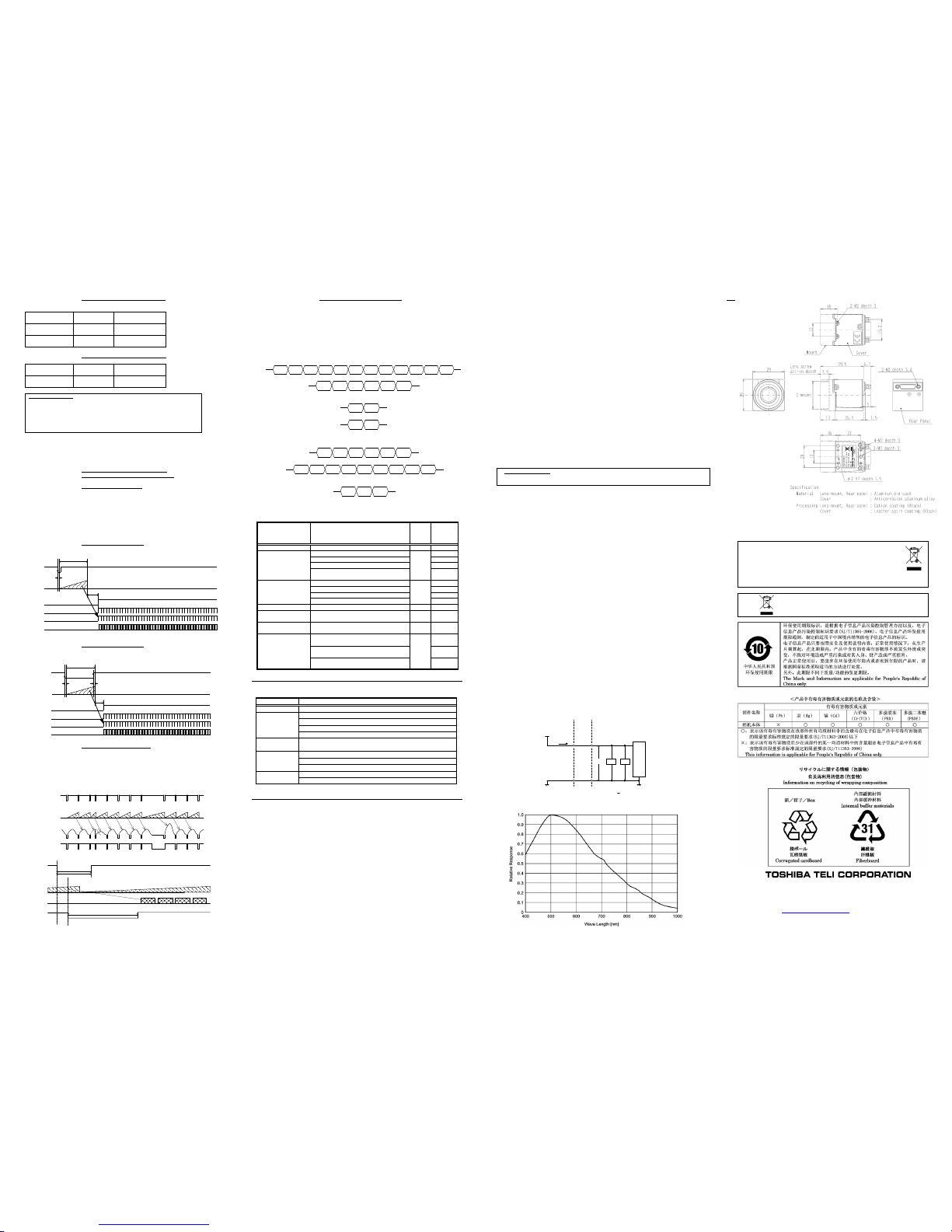
[Mechanical spec]
(1) Lens mount C-mount
*Depending on the lens you use, t he performance of the camera may not be brought out fully due to the
deterioration in resolution a nd brightness in t he peripheral area, occurrence of the ghost, aberration and
others. When you check the combination between the lens and camera, be sure to use the lens you
actually use.
*Install a next lens; t he C mount lens, its dimension of protrusion from flange is equal to or less than 7.9
mm. If a lens does not stand to this condition, it might not be installed to this camera.
(2) Flange back 17.526mm
(3) Dimensions 29mm(W) 29mm(H) 26.5mm(D)
* Not including protrusion
(4) Mass Approx. 45g
(5) Camera body grounding: Conductive between circuit GND and camera body
[Operating ambient conditions]
(1) Performance assurance Temperature: 0C to +40C
Humidity: 10% to 90% (no condensation)
(2) Operation guaranteed Temperature: -5C to +45C
Humidity: 90% or less (no condensation)
(3) Storage Temperature: -20C to +60C
Humidity: 95% or less (no condensation)
(4) EMC conditions (Electro-Magnetic Compatibility)
EMI (Electro-Magnetic Interference): EN61000-6-4
EMS (Electro-Magnetic Susceptibility): EN61000-6-2
(5) FCC FCC Part 15 Subpart B class A
*About the conformity of EMC standard of this machine, it has guaranteed in the conditions combined with our
system condition. When used combined parts other than specification of our company, I ask you to have final
EMC conformity checked of a visitor with a machine and the whole equipment.
[Communication specification]
(1) Communication speed 9600 bps ( fixed)
(2) Start bit 1
(3) Data bit 8
(4) Parity None
(5) Stop bit 1
(6) Handshake None
[Camera PSU input impedance]
Ci ≤ 57F, Rx = 10k ± 10%
PoCL
Cable
PSU
Test Circuit
CSCV90BC3
PSU
Camera
PSU
Ia
Rx Cx
Vb
Ia = 52uA, Vb = 0.52V, Cx < 50uF
Pin#: 1, 26
Pin#: 13, 14
[Relative Spectrum Response]
*The lens characteristics and light source characteristics are not reflected in table.
10. EXTERNAL VIEW DRAWING
[ UNIT : mm ]
Following information is only for EU-member states:
The use of the symbol indicates that this product may not be treated as household
waste. By ensuring this product is disposed of correctly, you will help prevent
potential negative consequences for the environment and human health, which
could otherwise be caused by inappropriate waste handling of this product.
For more detailed information about the take-back and recycling of this product, please
contact your supplier where you purchased the product.
”This symbol is applicable for EU member states only”
Head Office : 7-1, 4 chome, Asahigaoka, Hino-shi, Tokyo, 191-0065, Japan
(Overseas Sales Department)
Phone : +81-42-589-8771
FAX : +81-42-589-8774
URL : http://www.toshiba-teli.co.jp
The design and specification is subject to change without notice.
FVAL
DATA OUT
LVAL
DVAL
exposure time
TRIG
CCD
exposure
approx.
1.0usec
approx. 92.0usec (all pixel readout)
exposure time
approx. 1.0usec
approx. 2.9usec
FVAL
DATA OUT
LVAL
DVAL
TRIG
CCD
exposure
approx. 94.7usec (all pixel readout)
CCD exposure
Ext. VD input
Video Output
FVAL
Video output
CCD
exposure
Ext. VD input
FVAL
more than 1H
more than 72.2usec
when the external VD inputs to the camera while video output
Phenomena Check item
Cannot turn on power
Check th e connecttion of the C ameraLink(PoCL) frame grabber board and C ameraLink
Check th e connecttion of the C ameraLink(PoCL) frame grabber board and C ameraLink
Check th at the camera register are correct.
Check th at lens aperture is n ot closed .
Check th at the CameraLink(PoCL) grabber b oard is in stalled and set up co rrectly.
Frame drop pccurs o n
shooti ng image
If more than one b oards are installed in the P CI slots, remove the other b oards.
Check th at the camera is not in the rando m trigger mode.
Check th e setting o f the CameraLink(PoCL) grabber b oard.
Check th e connecttion of the C ameraLink(PoCL) frame grabber board and C ameraLink
Check th e connection of the C ameraLink cable.
Check th at the CameraLink(PoCL) grabber b oard is in stalled and set up co rrectly.
Shootin g image is n ot
displayed
Shootin g image
remains still
Cannot control camera
from PC
Address
2nd byte
Address
1st byte
‘ , ’
(0x2C)
Data
8th byte
Data
7th byte
Data
6th byte
Data
5th byte
Data
4th byte
Data
2nd byte
Data
1st byte
[CR]
(0x0D)
Data
3rd byte
‘7’
(0x37)
‘6’
(0x36)
‘ , ’
(0x2C)
‘3’
(0x33)
‘8’
(0x38)
[CR]
(0x0D)
[ACK]
(0x06)
[CR]
(0x0D)
[NAK]
(0x15)
[CR]
(0x0D)
‘9’
(0x39)
‘1’
(0x31)
‘ , ’
(0x2C)
‘R’
(0x52)
‘Q’
(0x51)
[CR]
(0x0D)
Data
8th byte
Data
7th byte
Data
6th byte
Data
5th byte
Data
4th byte
Data
2nd byte
Data
1st byte
[CR]
(0x0D)
Data
3rd byte
‘1’
(0x31)
‘0’
(0x30)
[CR]
(0x0D)
Error type Details of error
Status
[0x69]
Expansio n
Status
[0x6A]
No Error
No error 0x00 0x00
A packet format error was detected. 0x01
An overrun error was detected. 0x02
An framing error was detected. 0x03
The data length of the co mmand is beyo nd th e
specified up per limit.
0x04
The reserved area was accessed. 0x01
You attemped a read access to a Write Onl y Register. 0x02
You attemped a write access to a Read On ly Regis ter. 0x03
The setting v alue is o ut of the specified range. 0x04
FlashRom Accessin g Error
FlashRom access error 0x03 0x01
User Setting Read Error
You load you r saved settin g when an y saved setting
data is no t available.
0x04 0x01
Partial Mode Related Error
You chan ged registers related p artial scan mode when
you s elect all pixel read-ou t mode.
0x05 0x01
You attempted to set a sh utter speed b eyond the
specified range.
0x01
You chan ged Rand om Trigger shu tter mode when
you s elect Normal Shutter mode or R estart-Reset
0x02
You chan ged trigg er polarity when you select Normal
Shutter mode.
0x03
Shutter Related Error
General Accessing Error
Communication Error
0x01
0x02
0x06
 Loading...