

Page 1

®
Satellite Pro
6000
Series
User’s Guide
If you need assistance:
❖ V irtualTech™ e-support tool
Double-click the desktop icon or visit the Web site:
http://virtualtech.answerteam.com
❖ InTouch
For more information, see Chapter 9 on page 201 of this guide.
TOSHIBA
sm
Center
Calling within the United States (800) 457-7777
Calling from outside the United States (949) 859-4273
C6602-1001M1
Page 2

2
Models: Satellite Pro® 6000 Series
Compact Disk-Read/Write
The computer system you purchased may include a Compact Disk-Read/Write
(CD-RW), one of the most adv anced storage technologies av ailable. As with an y
new technology , you must read and follo w all set-up and usage instructions in the
applicable user guides and/or manuals enclosed. If you fail to do so, this product
may not function properly and you may lose data or suffer other damage.
TOSHIBA AMERICA INFORMATION SYSTEMS (“ TOSHIBA”), ITS
AFFILIATES AND SUPPLIERS DO NO T WARRANT THAT OPERATION
OF THE PRODUCT WILL BE UNINTERR UPTED OR ERR OR FREE. YO U
AGREE THAT TOSHIB A, ITS AFFILIATES AND SUPPLIERS SHALL
HAVE NO RESPONSIBILITY FOR DAMA GE T O OR LOSS OF ANY
BUSINESS, PR OFITS, PR OG RAMS, D ATA OR REMO VABLE ST ORA GE
MEDIA ARISING OUT OF OR RESUL TING FR OM THE USE OF THE
PRODUCT, EVEN IF ADVISED OF THE POSSIBILITY THEREOF.
Protection of Stored Data
For your important data, please make periodic back-up copies of all the data
stored on the hard disk or other storage devices as a precaution against possible
failures, alteration, or loss of the data. IF YOUR D ATA IS AL TERED OR LOST
DUE TO ANY TR OUBLE, FAILURE OR MALFUNCTION OF THE HARD
DISK DRIVE OR OT HER STORA GE DEVICES AND THE D A TA CANNOT
BE RECOVE RED, TO SHIB A SHALL NOT BE LIABLE FOR ANY
DAMA GE OR LOSS OF D ATA, OR ANY OTHER DAMA GE RESULTING
THEREFROM. WHEN COPYING OR TRAN SFERRING Y OUR D ATA,
PLEASE BE SURE TO CONFIRM WHETHER THE DATA HAS BEEN
SUCCESSFULLY COPIED OR TRANSFERRED. TOSHIB A DISCLA IMS
ANY LIABILITY FOR THE F AILURE T O COPY OR TRANSFER THE
DATA CORRECTL Y.
Critical Applications
The computer you have purchased is not designed for any “critical applications.”
“Critical applications” means life support systems, medical applications,
connections to implanted medical devices, commercial transportation, nuclear
facilities or systems or any other applications where product failure could lead to
injury to persons or loss of life or catastrophic property damage.
Page 3

ACCORDINGLY, TOSHIBA, ITS AFFILIATES AND SUPPLIERS
DISCLAIM ANY AND ALL LIABILITY ARISING OUT OF THE USE OF
THE COMPUTER PRODUCTS IN ANY CRITICAL APPLICATIONS. IF
YOU USE THE COMPUTER P RODUCTS IN A CRITICAL APPLICATION,
YOU, AND NO T T OSHIB A, ASSUM E FULL RESPONSIBILITY FO R
SUCH USE.
FCC Notice “Declaration of Conformity
Information”
This equipment has been tested and found to comply with the limits for a Class B
digital device, pursuant to Part 15 of the FCC rules. These limits are designed to
provide reasonable protection against harmful interference in a residential
installation.
This equipment generates, uses and can radiate radio frequency energy and, if not
installed and used in accordance with the instructions, it may cause harmful
interference to radio communications. However , there is no guarantee that
interference will not occur in a particular installation. If this equipment does
cause harmful interference to radio or television reception, which can be
determined by turning the equipment off and on, the user is encouraged to try to
correct the interference by one or more of the following measures:
3
❖ Reorient or relocate the receiving antenna.
❖ Increase the separation between the equipment and receiver.
❖ Connect the equipment to an outlet on a circuit different from that to which
the receiver is connected.
❖ Consult the dealer or an experienced radio/TV technician for help.
NOTE: Only peripherals complying with the FCC Class B limits may be
attached to this computer. Operation with non-compliant peripherals or
peripherals not recommended by Toshiba is likely to result in interference
to radio and TV reception. Shielded cables must be used between the
external devices and the computer’s serial port, parallel port, monitor port,
USB port, PS/2™ port and microphone jack. Changes or modifications
made to this equipment not expressly approved by Toshiba or parties
authorized by Toshiba could void the user
equipment.
This device complies with Part 15 of the FCC Rules. Operation is subject to the
following two conditions:
’s authority to operate the
Page 4

4
❖ This device may not cause harmful interference.
❖ This device must accept an y interference recei v ed, including interference
that may cause undesired operation.
Contact:
T oshiba Americ a Information Systems, Inc.
9740 Irvine Blvd.
Irvine, CA 92618-1697
(949) 583-3000
Industry Canada requirement
This Class B digital apparatus complies with Canadian ICES-003.
Cet appareil numérique de la classe B est conformé à la norme NMB-003 du
Canada.
FCC requirements
The following information is pursuant to FCC CFR 47, Part 68 and refers to
internal modems.
Installation
When you are ready to install or use the modem, call your local telephone
company and give them the follo wing information:
❖ The telephone number of the line to which you will connect the modem.
❖ The FCC registration number of the modem.
❖ The Ringer Equivalence Number (REN) of the modem, which is 0.6B.
The modem connects to the telephone line by means of a standard jack called the
USOC RJ11C.
Type of service
Your modem is designed to be used on standard-device telephone lines.
Connection to telephone company-provided coin service (central office
implemented systems) is prohibited. Connection to party lines service is subject
to State tariffs. If you hav e any questions about your telephone line, such as ho w
Page 5

many pieces of equipment you can connect to it, the telephone company will
provide this information upon request.
Telephone company procedures
The goal of the telephone company is to provide you with the best service it can.
In order to do this, it may occasionally be necessary for them to make changes in
their equipment, operations or procedures. If these changes might affect your
service or the operation of your equipment, the telephone company will give you
notice, in writing, to allow you to make any changes necessary to maintain
uninterrupted service.
If problems arise
If any of your telephone equipment is not operating properly , you should
immediately remove it from your telephone line, as it may cause harm to the
telephone network. If the telephone company notes a problem, they may
temporarily discontinue service. When practical, they will notify you in advance
of this disconnection. If advance notice is not feasible, you will be notified as
soon as possible. When you are notified, you will be given the opportunity to
correct the problem and informed of your right to file a complaint with the FCC.
In the event repairs are ev er needed on your modem, they should be performed by
T oshiba Corporation or an authorized representati ve of Toshiba Corporation.
5
Disconnection
If you should ever decide to permanently disconnect your modem from its
present line, please call the telephone company and let them know of this change.
Fax branding
The T elephone Consumer Protection Act of 1991 makes it unla wful to use a
computer or other electronic device to send any message via a telephone f ax
machine unless such message clearly contains in a margin at the top or bottom of
each transmitted page or on the first page of the transmission, the date and time it
is sent and an identification of the business, other entity or individual sending the
message and the telephone number of the sending machine or such business,
other entity or individual.
In order to program this information into your fax modem, you should complete
the setup for your fax software before sending a message.
Page 6

6
Instructions for IC CS-03 certified equipment
1 NOTICE: The Industry Canada label identif ies certif ied
equipment. This certification means that the equipment meets
certain telecommunications network protecti ve, operational
and safety requirements as prescribed in the appropriate
T erminal Equipment Technical Requirements document(s).
The Department does not guarantee the equipment will
operate to the user’ s satisfaction.
Before installing this equipment, users should ensure that it is
permissible to be connected to the facilities of the local
telecommunications company. The equipment must also be
installed using an acceptable method of connection. The
customer should be aware that compliance with the abov e
conditions may not prevent de gradation of service in some
situations.
Repairs to certified equipment should be coordinated b y a
representativ e designated by the supplier. Any repairs or
alterations made by the user to this equipment, or equipment
malfunctions, may give the telecommunications compan y
cause to request the user to disconnect the equipment.
Users should ensure for their own protection that the electrical
ground connections of the power utility, telephone lines and
internal metallic water pipe system, if present, are connected
together . This precaution may be particularly important in
rural areas.
Caution: Users should not attempt to make such connections
themselves, but should contact the appropriate electric
inspection authority , or electrician, as appropriate.
2 The user manual of analog equipment must contain the
equipment’ s Ringer Equiv alence Number (REN) and an
explanation notice similar to the following:
The Ringer Equiv alence Number (REN) of this device can be
found on the label affi xed to your computer.
Page 7

NOTICE: The Ringer Equi v alence Number (REN) assigned
to each terminal device provides an indication of the
maximum number of terminals allowed to be connected to a
telephone interface. The termination on an interface may
consist of any combination of devices subject only to the
requirement that the sum of the Ringer Equivalence Numbers
of all the devices does not exceed 5.
3 The standard connecting arrangement (telephone jack type)
for this equipment is jack type(s): USOC RJ11C.
Wireless Interoperability
The T oshiba W ireless LAN Mini PCI Card products are designed to be
interoperable with any wireless LAN product that is based on Direct Sequence
Spread Spectrum (DSSS) radio technology , and is compliant to:
❖ The IEEE 802.11 Standard on Wireless LANs (Revision B), as def ined and
approved by the Institute of Electrical and Electronics Engineers.
7
❖ The Wireless Fidelity (Wi-Fi™) certification as defined by the WECA
Wireless Ether net Compatibility Alli ance.
Wireless LAN and your Health
Wireless LAN products, like other radio de vices, emit radio frequency
electromagnetic energy. The le vel of energy emitted by Wireless LAN devices
howev er is far much le ss than the electromagne tic energy e mitted by wire less
devices like for example mobile phones. Because W ireless LAN products
operate within the guidelines found in radio frequency safety standards and
recommendations, T oshiba belie ves W ireless LAN is safe for use by consumers.
These standards and recommendations reflect the consensus of the scientific
community and result from deliberations of panels and committees of scientists
who continually review and interpret the extensi ve research literature.
In some situations or environments, the use of Wireless LAN may be restricted
by the proprietor of the building or responsible representatives of the
organization. These situations may for example include:
❖ Using the Wireless LAN equipment on board of airplanes, or
❖ In any other environment where the risk of interference to other devices or
services is perceived or identif ied as harmful.
Page 8

8
If you are uncertain of the policy that applies on the use of wireless devices in a
specific organization or environment (e.g., airports), you are encouraged to ask
for authorization to use the Wireless LAN de vice prior to turning on the
equipment.
Regulatory Information
The T oshiba W i reless LAN Mini PCI Card must be installed and used in strict
accordance with the manufacturer’s instructions as described in the user
documentation that comes with the product. This device complies with the
following radio frequency and safety standards.
Canada – Industry Canada (IC)
This device complies with RSS 210 of Industry Canada.
Operation is subject to the following two conditions: (1) this device may not
cause interference, and (2) this device must accept an y interference, including
interference that may cause undesired operation of this device.
USA-Federal Communications Commission (FCC)
This device complies with Part 15 of FCC Rules. Operation of the de vices in a
Wireless LAN System is subject to the follo wing two conditions:
❖ This device may not cause harmful interference.
❖ This device must accept an y interference that may ca use undesired
operation.
Caution: Exposure to Radio Frequency Radiation
The radiated output power of the Toshiba Wireless LAN Mini PCI Card is far
below the FCC radio frequency e xposure limits. Ne v ertheless, the Toshiba
Wireless LAN Mini PCI Card shall be used in such a manner that the potential
for human contact during normal operation is minimized. When using this device
in combination with Wireless LAN Outdoor Antenna products, a certain
separation distance between antenna and nearby persons has to be kept to ensure
RF exposure compliance. The distance between the antennas and the user should
not be less than 20.0 cm.
Refer to the Regulatory Statements as identified in the documentation that comes
with those products for additional information.
Page 9

The T oshiba W irele ss LAN Mini PCI Card is far belo w the FCC radio frequency
exposure limits.
Nevertheless, it is advised to use the Toshiba Wireless LAN Mini PCI Card in
such a manner that human contact during normal operation is minimized.
Interference Statement
This equipment has been tested and found to comply with the limits for a Class B
digital device, pursuant to Part 15 of the FCC Rules. These limits are designed to
provide reasonable protection against harmful interference in a residential
installation. This equipment generates, uses, and can radiate radio frequency
energy . If not installed and used in accordance with the instructions, it may cause
harmful interference to radio communications. However , there is no guarantee
that interference will not occur in a particular installation.
If this equipment does cause harmful interference to radio or television reception,
which can be determined by turning the equipment off and on, the user is
encouraged to try and correct the interference by one or more of the following
measures:
9
❖ Reorient or relocate the receiving antenna.
❖ Increase the distance between the equipment and the rece iv er.
❖ Connect the equipment to an outlet on a circuit different from that to which
the receiver is connected.
❖ Consult the dealer or an experienced radio/TV technician for help.
T oshiba is not responsible for an y radio or tele vision interference caused by
unauthorized modification of the devices included with this Toshiba Wireless
LAN Mini PCI Card, or the substitution or attachment of connecting cables and
equipment other than specified by Toshiba.
The correction of interference caused b y such unauthorized modif ication,
substitution or attachment will be the responsibility of the user.
Page 10

10
Approved Countries for use
This equipment is approved to the radio standard by the countries in Fig.1.
Australia Austria Belgium
Canada Denmark Finland
Germany Iceland Ireland
Japan Luxembourg Netherlands
New Zealand Norway Sweden
Switzerland UK USA
Greece Italy France
Poland Portugal Spain
Caution: Do not use this equipment except in the countries in Fig.1.
CD-ROM, DVD-ROM, DVD-ROM/CD-RW
safety instructions
The CD-ROM,D VD-R OM, DVD-ROM/CD-RW dri v es employ a laser
system. To en sure proper use of this product, please read this instruction
manual carefully and retain for future reference. Should the unit ever
require maintenance, contact an authorized service location.
Use of controls, adjustments or the performance of procedures other than those
specified may result in hazardous radiation exposure.
T o pre vent direct e xposure to the laser beam, do not try to open the enclosure.
Page 11
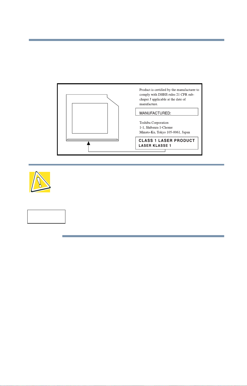
Location of the required label
(Sample shown below . Location of the label and manuf acturing information may
vary.)
CAUTION: This appliance contains a laser system and is classified as a “CLASS
1 LASER PRODUCT.” To use this model properly, read the instruction manual
carefully and keep it for your future reference. In case of any trouble with this
model, please contact your nearest “AUTHORIZED service station.” To prevent
direct exposure to the laser beam, do not try to open the enclosure.
11
CLASS 1 LASER PRODUCT
LASER KLASSE 1
Use of controls or adjustments or performance of
procedures other than those specified in the owner’s
manual may result in hazardous radiation exposure.
Copyright
This guide is copyrighted by T oshiba America Information Systems, Inc. with all
rights reserved. Under the copyright laws, this guide cannot be reproduced in any
form without the prior written permission of T oshiba. No patent liability is
assumed, however , with respect to the use of the information contained herein.
©2001 by Toshiba American Information Systems, Inc. All rights reserved.
Export Administration regulation
This document contains technical data that may be controlled under the U.S.
Export Administration Regulations, and may be subject to the approval of the
Page 12

12
Notice
U.S. Department of Commerce prior to export. Any export, directly or indirectly,
in contravention of the U.S. Export Administration Regulations is prohibited.
The information contained in this manual, including but not limited to any
product specifications, is subject to change without notice.
TOSHIBA CORPORATION AND TOSHIBA AMERICA
INFORMATION SYSTEMS, INC. (TOSHIBA) PROVIDES NO
WARRANTY WITH REGARD TO THIS MANUAL OR ANY
OTHER INFORMATION CONTAINED HEREIN AND HEREBY
EXPRESSLY DISCLAIMS ANY IMPLIED WARRANTIES OF
MERCHANTABILITY OR FITNESS FOR ANY PARTICULAR
PURPOSE WITH REGARD TO ANY OF THE FOREGOING.
TOSHIBA ASSUMES NO LIABILITY FOR ANY DAMAGES
INCURRED DIRECTLY OR INDIRECTLY FROM ANY
TECHNICAL OR TYPOGRAPHICAL ERRORS OR OMISSIONS
CONTAINED HEREIN OR FOR DISCREPANCIES BETWEEN
THE PRODUCT AND THE MANUAL. IN NO EVENT SHALL
TOSHIBA BE LIABLE FOR ANY INCIDENTAL,
CONSEQUENTIAL, SPECIAL, OR EXEMPLARY DAMAGES,
WHETHER BASED ON TORT, CONTRACT OR OTHERWISE,
ARISING OUT OF OR IN CONNECTION WITH THIS MANUAL
OR ANY OTHER INFORMATION CONTAINED HEREIN OR THE
USE THEREOF.
Trademarks
Satellite, AccuPoint II, Fn-esse, Noteworthy, and SelectBay are registered
trademarks, SelectServ, Ask IRIS Online, and VirtualTech are trademarks, and
InT ouch is a service mark of Toshiba America Information Systems, Inc. and/or
T oshiba Corporation.
IBM and W ake on LAN are registered trademarks and PS/2 is a trademark of
IBM Corporation.
MS-DOS, Microsoft, Windo ws, W indo ws 2000, W indows XP, Media Player ,
DirectX, and DirectShow are re gistered trademarks of Microsoft Corporation.
Intel and Pentium are registered trade marks and SpeedStep is a trademark of Intel
Corporation.
LapLink is a registered trademark of Tra veling Softw are, Inc.
Page 13

13
WinDVD™ is a trademark of InterVideo, Inc.
Sound Blaster Pro is a registered trademark of Creativ e Labs, Inc.
™
SPANWorks 2000
™
Wi-Fi
Yamaha is a registered trademark of Y amaha Corporation.
*Manufactured under license from Dolby Laboratories. “Dolby” and “Dolby
Digital” are registered trademarks of Dolby Laboratories.
Energy Star is a register ed trademark of the U.S. En vironmental Protection
Agency .
Bluetooth
license.
All other brand and product names are trademarks or registered trademarks of
their respective companies.
is a trademark of the Wireless Capability Ethernet Alliance.
™
is a trademark owned by its proprietor and used by Toshiba under
is a trademark of SP ANWorks, U.S.A.
Energy Star compliance
As an Energy Star® partner, Toshiba has determined that this product is Energy
Star Compliant.
Computer disposal information
This product contains mercury . Disposal of this material may be re gulated due to
environmental considerations. For disposal, reuse or rec ycling information,
please contact your local government or the Electronic Industries Alliance at
www .eiae .org.
Page 14

14
- Blank Page -
Page 15

Contents
Introduction............................................................................... 23
This guide............................................................................... 23
Safety icons............................................................................ 24
Other icons used............................................................... 25
Other documentation............................................................ 25
Service options...................................................................... 26
Chapter 1: Finding Your Way Around ..................................... 27
Making sure you have everything........................................ 27
Front with the display panel closed................................. 28
Back with rear panel closed ............................................. 29
Back with rear panel open................................................ 30
Right side........................................................................... 31
Left side.............................................................................. 31
Underside........................................................................... 33
Keyboard and display features............................................. 34
Front with the display panel open.................................... 34
Indicator panel lights......................................................... 36
Keyboard indicator panel lights ....................................... 37
Chapter 2: Getting Started........................................................ 39
15
Page 16

16
Selecting a place to work...................................................... 39
Creating a computer-friendly environment.................... 39
Keeping yourself comfortable.......................................... 40
Other precautions ................................................................. 43
Setting up your computer.................................................... 44
Connecting to a power source......................................... 45
Turning on the computer...................................................... 47
Opening the display panel................................................ 47
Turning on the power ...................................................... 48
Using the AccuPoint II pointing device............................... 49
Setting up your software...................................................... 50
Setting up other devices................................................... 51
Turning off the computer...................................................... 52
Closing the display panel ................................................. 52
Chapter 3: Connecting Other External Devices....................... 55
Using external display devices............................................. 55
Connecting the display device......................................... 56
Directing the display output when you turn on the
computer........................................................................... 57
Adjusting the quality of the external display................... 58
Video limitations ............................................................... 58
Using an external keyboard.................................................. 59
Making your external keyboard emulate the Fn key...... 59
Using a mouse...................................................................... 60
Setting up a PS/2 mouse with the AccuPoint II............. 60
Connecting a local printer .................................................... 61
Connecting an external diskette drive.................................. 62
Connecting external speakers or headphones................... 63
Connecting a microphone.................................................... 63
Using an expansion device................................................... 64
Adding memory.................................................................... 64
Memory module sizes...................................................... 65
Installing a memory module............................................ 66
Removing a memory module......................................... 68
Page 17

17
Using Slim SelectBay® modules........................................ 69
Removing a module from the Slim SelectBay® ........... 70
Inserting a module into the Slim SelectBay®................ 71
Inserting and removing hard drives .................................... 71
Inserting and removing PC Cards........................................ 73
Inserting a PC Card........................................................... 73
Removing a PC Card........................................................ 75
Inserting and removing Bluetooth™ modules............... 76
Setting up a PC Card for your computer ........................ 76
Using Secure Digital cards ................................................... 76
Inserting an SD Media™ card.......................................... 77
Removing an SD Media™ card ....................................... 77
Connecting your modem to a telephone line...................... 78
Connecting to a phone line............................................... 78
Chapter 4: Learning the Basics................................................ 81
Computing tips...................................................................... 81
Using the keyboard............................................................... 82
Character keys .................................................................. 83
Making your keyboard emulate a full-size keyboard ..... 83
Ctrl, Fn, and Alt keys ......................................................... 84
Function keys .................................................................... 84
Windows special keys...................................................... 84
Overlay keys ..................................................................... 85
Starting a program................................................................ 87
Starting a program from the Start menu........................ 87
Starting a program from Windows® Explorer.............. 88
Starting a program from the Run dialog box................. 89
Saving your work .................................................................. 90
Printing your work................................................................. 92
Using a compact disc drive.................................................. 93
Inserting compact discs .................................................. 94
Removing compact discs ............................................... 96
Caring for CDs and DVDs ................................................ 97
Using PC Cards ..................................................................... 98
Page 18

18
Hot swapping.................................................................... 98
Using SD Media cards.......................................................... 99
Using your computer at the office....................................... 99
Using a computer lock........................................................ 100
Caring for your computer................................................... 101
Cleaning the computer................................................... 101
Moving the computer..................................................... 102
Backing up your work......................................................... 102
Restoring your work....................................................... 103
Preparing for communications.......................................... 103
Different ways to turn the computer on and off............... 104
Powering down the computer........................................... 105
Using Turn Off Computer............................................... 105
Using Hibernation........................................................... 108
Using Standby................................................................. 110
Toshiba’s online resources................................................. 113
Chapter 5: Power Management............................................. 115
Toshiba’s energy-saver design........................................... 115
Running the computer on battery power ......................... 116
Charging the batteries.................................................... 116
Monitoring battery power.............................................. 117
What to do when the battery alarm sounds..................... 119
Changing batteries.............................................................. 120
Taking care of your battery................................................. 123
Safety precautions.......................................................... 123
Maximizing battery life ................................................... 123
Disposing of used batteries........................................... 124
Conserving power............................................................... 124
Power usage modes in Windows XP Professional..... 125
Using a hot key to set the power usage mode............. 125
Additional options for power.............................................. 126
Chapter 6: Exploring Your Options........................................ 127
Exploring the desktop......................................................... 127
Page 19

19
Finding your way around the desktop........................... 127
Exchanging data with another computer.......................... 130
Transferring files.............................................................. 131
Getting help transferring files......................................... 131
Setting up for communications..................................... 131
Connecting the modem to a telephone line.................. 133
Connecting your computer to a network ..................... 133
An overview of using the Internet...................................... 137
The Internet...................................................................... 137
The World Wide Web .................................................... 138
Internet Service Providers.............................................. 138
Connecting to the Internet ............................................. 138
Surfing the Internet......................................................... 139
Internet features.............................................................. 139
Uploading and downloading files from the Internet ... 140
Exploring audio features..................................................... 140
Playing an audio CD........................................................ 141
Creating a CD................................................................... 142
Recording sounds .......................................................... 142
Using external speakers or headphones....................... 144
Exploring audiovisual features ........................................... 144
Playing DVDs....................................................................... 145
Using the WinDVD toolbar............................................. 146
Using the WinDVD status bar........................................ 147
Using the WinDVD control panel................................... 147
Using the control panel playback buttons .................... 148
Maximizing the video window....................................... 150
Using playlists...................................................................... 151
Creating playlists............................................................. 151
Loading and playing playlists......................................... 152
Resuming normal playback after using playlists......... 153
Customizing WinDVD......................................................... 153
Setting general properties.............................................. 154
Setting audio properties................................................. 155
Page 20

20
Setting display properties .............................................. 157
Using WinDVD advanced features.................................... 158
Zooming in...................................................................... 162
Zooming out.................................................................... 162
Panning............................................................................ 162
Adjusting the color balance ........................................... 163
Launching an Internet browser from WinDVD................ 163
Getting help.......................................................................... 163
Exiting WinDVD................................................................... 164
Chapter 7: Expansion Options ............................................... 165
Devices for office computing............................................. 165
Connecting external (optional) devices......................... 166
Using a mouse ................................................................... 167
Connecting a serial mouse ............................................ 167
Connecting a USB mouse.............................................. 167
Connecting a PS/2 mouse............................................. 168
Using a printer .................................................................... 169
Connecting a parallel printer.......................................... 170
Setting up your printer................................................... 171
Using an external monitor.................................................. 174
Connecting the display device....................................... 175
Directing the display output when you turn on the
computer......................................................................... 177
Adjusting the quality of the external display................. 177
Video limitations ............................................................. 178
Using the Wi-Fi
Accessing the Wi-Fi
Using an expansion device................................................. 179
™
Mini PCI module.................................. 178
™
Mini PCI module...................... 178
Chapter 8: Toshiba Utilities..................................................... 181
Fn-esse................................................................................. 182
Starting Fn-esse.............................................................. 182
Using the keyboard or pointing device to assign keys 184
Viewing existing key assignments................................ 185
Page 21

21
Changing or removing existing key assignments ....... 186
Hotkey utility ........................................................................ 186
Toshiba Console .................................................................. 187
Customizing Your Computer ......................................... 188
Network............................................................................ 189
Security............................................................................ 189
Power Management....................................................... 189
Slim SelectBay™ and Docking........................................... 192
Mobile Extension Service............................................... 192
Slim SelectBay™ Service ............................................... 193
Toshiba Hardware Setup .................................................... 193
Toshiba Power Saver utility ................................................ 195
Enabling Hibernation........................................................... 195
Setting user passwords...................................................... 196
Using an instant password ............................................ 197
Setting a user password................................................. 197
Disabling a user password............................................. 198
Using a supervisor password ............................................ 198
Setting a supervisor password...................................... 198
Deleting a supervisor password.................................... 199
Chapter 9: If Something Goes Wrong .................................. 201
Problems that are easy to fix.............................................. 201
Problems when you turn on the computer....................... 203
The Windows® operating system is not working........... 204
Using Startup options to fix problems.......................... 205
Internet problems............................................................ 206
The Windows® XP operating system can help you... 206
Resolving a hardware conflict............................................ 207
A plan of action................................................................ 207
Resolving hardware conflicts on your own.................. 208
Fixing a problem with Device Manager......................... 209
Memory problems.......................................................... 211
Power and the batteries.................................................. 211
Keyboard problems........................................................ 213
Page 22

22
Display problems............................................................ 213
Disk drive problems ....................................................... 215
DVD-ROM or DVD-ROM/CD-RW drive problems...... 218
Sound system problems ............................................... 225
PC Card problems.......................................................... 226
Printer problems............................................................. 229
Modem problems........................................................... 230
Develop good computing habits ....................................... 230
Using VirtualTech................................................................ 232
If you need further assistance............................................ 232
Before you call................................................................. 233
Contacting Toshiba......................................................... 233
Other Toshiba Internet Web sites ...................................... 234
Toshiba’s worldwide offices............................................... 235
Appendix A: Hot Keys............................................................. 239
Appendix B: Power Cable Connectors.................................. 247
Appendix C: Video Modes...................................................... 249
Glossary................................................................................... 251
Index......................................................................................... 267
Page 23

Introduction
Welcome to the world of powerful, portable multimedia
computing. With your Toshiba notebook computer , your work can
accompany you wherev er you go.
Satellite Pro
computing power , enabling you to perform the most demanding
computing tasks from any location.
You will find that your ope rating system, Microsoft
XP Professional, is already installed on your computer . It of fers
exciting features and easy Internet access.
This guide
This guide introduces the computer’ s features. You can:
❖ Read the entire guide from beginning to end
❖ Skim through and stop when a topic interests you
❖ Use the table of contents and the index to find specif ic
information
®
6000 Series computers provide considerable
®
Windows®
23
Page 24

24
Safety icons
If you are new to computers or have not use d a notebook computer
before, read through this chapter to familiarize yo urself with the
components of the computer . After that, seek out whate ver
interests you most.
Safety icons
This guide contains safety instructions that must be observed in
order to avoi d potential hazards that could result in personal
injuries, damage to your equipment, or loss of data. The safety
instructions have been classif ied according to the seriousness of
risk; the following icons highlight these instructions:
DANGER: This icon indicates the existence of a hazard that
could result in death or serious bodily injury if the safety
instruction is not observed.
WARNING: This icon indicates the existence of a hazard that
could result in bodily injury if the safety instruction is not
observed.
CAUTION: This icon indicates the existence of a hazard that
could result in damage to equipment or property if the safety
instruction is not observed.
NOTE: This icon indicates information that relates to the safe
operation of the equipment or related items.
Page 25
Other icons used
Additional icons highlight other helpful or educational
information:
TECHNICAL NOTE: This icon indicates technical information
about the computer.
HINT: This icon indicates helpful hints and tips.
DEFINITION: This icon indicates the definition of a term used
in the text.
Other documentation
25
Other documentation
Your computer comes with the following documentation in
addition to this user’ s guide.
❖ An electronic version of the user’ s guide. Look for the user’s
guide icon on your desktop or in the DOCS folder on the C:
drive.
❖ Guides for other programs that may come preinstalled on
your computer or that are available for installation on your
Recovery and Configuration Builder CD.
❖ Toshiba accessories information, which lists accessories
available from Toshiba and explains ho w to order them.
❖ The Microsoft
which explains the features of the operating system.
®
Windows® operating system documentation
Page 26

26
Service options
Service options
T o shiba offers a full line of service options b uilt around its
SelectServ
T o shiba’ s Web site at Toshiba.com.
If you have a problem or need to contact Toshiba, see “If
Something Goes Wrong” on page 201.
™
warranty programs. For more information, visit
Page 27

Chapter 1
Finding Your Way
Around
This chapter presents a grand tour of your Satellite Pro® 6000
Series computer . It serves as a reference to locate specif ic parts of
the computer .
Making sure you have everything
Before you do anything else, consult the Quick Start card shipped
with your computer to make sure you receiv ed e verything.
If any items are missing or damaged, notify your authorized
Toshiba representative or your netw ork administrator
immediately . F or additional help, see “If Something Goes
Wrong” on page 201.
27
Page 28
Finding Your Way Around
28
Making sure you have e verything
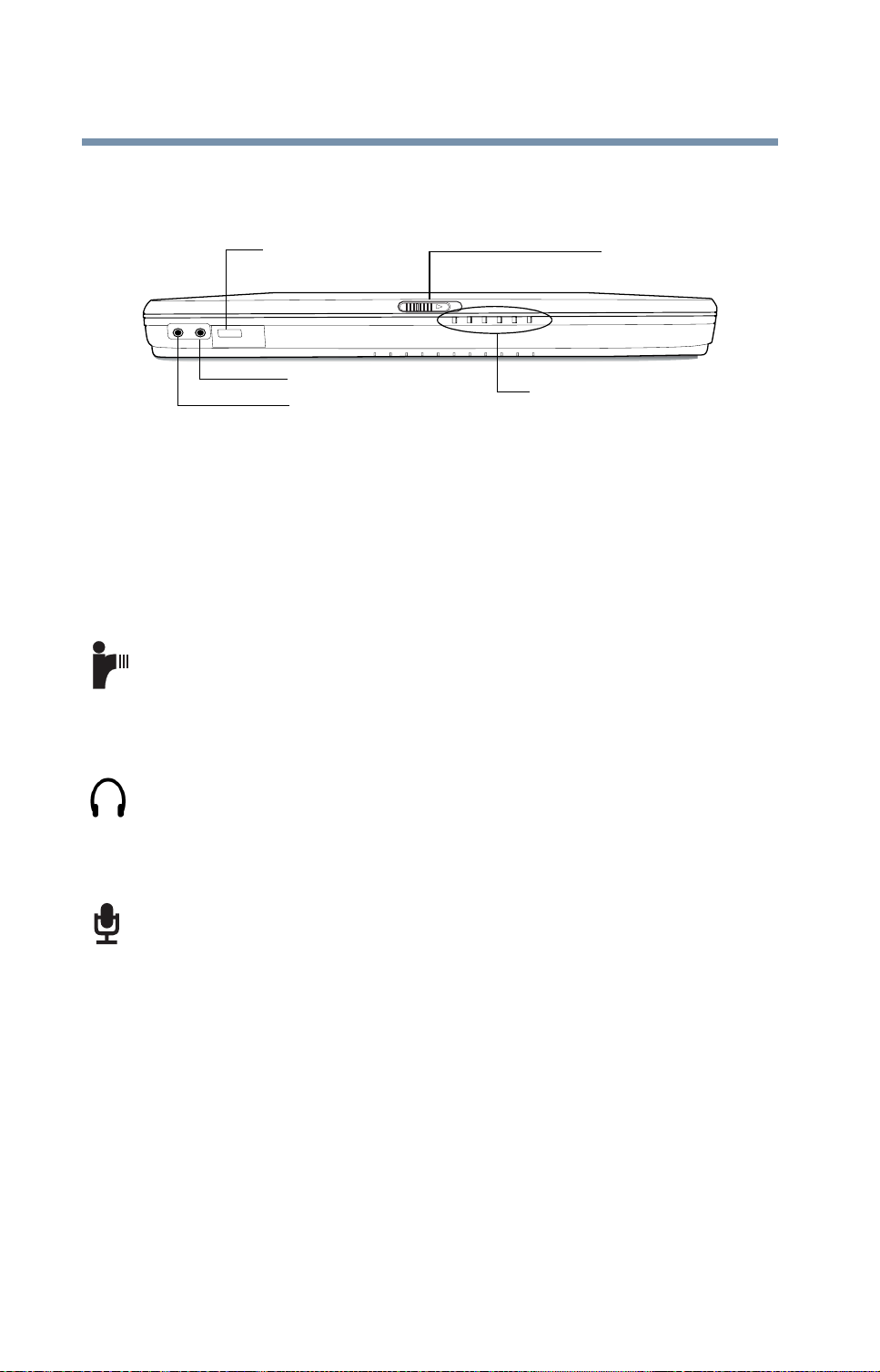
Front with the display panel closed
Infrared port
Headphone jack
Microphone jack
Sliding the display latch opens the computer’ s display panel. For
more information, see “Keyboard and display features” on
page 34
The system indicator panel consists of several lights that pro vide
information about v arious system functions. F or more
information, see “Indicator panel lights” on page 36.
The infrared port provides a cable-free connection for
transferring data between your computer and another device, such
as a printer or another computer that has a compatible infrared
port.
.
System indicator panel
Display Latch
The headphone jack allows you to connect stereo headphones or
other audio-output devices, such as e xternal speakers, to the
computer . Connecting headphones or other de vices to this jack
automatically disables the internal speakers.
The microphone jack allows you to conn ect an external
microphone or other audio input device to the computer.
Page 29
Making sure you have e verything
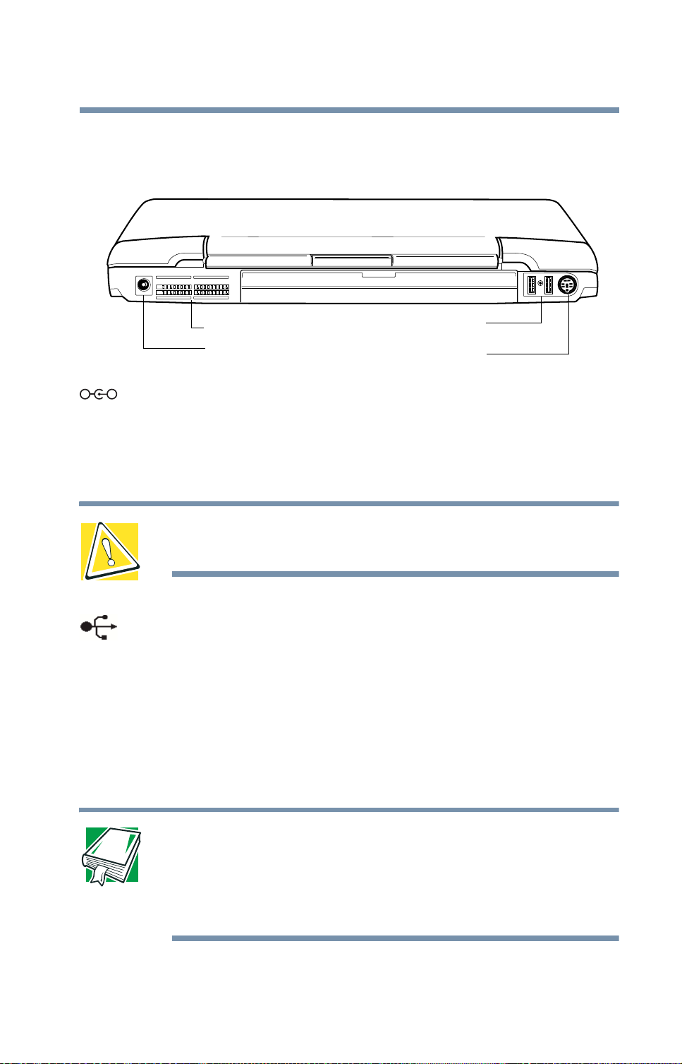
Back with rear panel closed
Finding Your Way Around
29
Cooling vent
DC IN socket
_
+
DC IN socket—Lets you plug in the A C adapter .
USB ports
PS/2 port
Cooling vent—Provides v entilation to keep the comput er’s
processor from overheating. The vent lets t he processor continue
performing at its maximum speed.
CAUTION: To prevent possible overheating of the computer’s
processor, make sure you don’t block the cooling vent.
USB ports—The USB (Universal Serial Bus) ports pro vide a
connection for USB peripherals. USB is a single-cabling and
connection standard that supports a data transfer rate of up to
12 million bits per second (Mbps) for peripherals such as
keyboards, pointing de vices, a diskette dri ve and a video camera.
USB allows “hot swapping” of peripherals, whi ch means that
components may be plugged and unplugged while the computer is
on.
DEFINITION: USB is a peripheral expansion standard that
supports a data-transfer rate of up to 12 Mbps for
peripherals such as keyboards, pointing devices, and
monitors. USB peripherals have a single standard for
cabling and connectors.
Page 30
Finding Your Way Around
30
Making sure you have e verything
™
PS/2
port—Lets you connect an optional PS/2-compatible
mouse or keyboard. You can use an optional Y-cable to connect
both a mouse and a keyboard to the port.
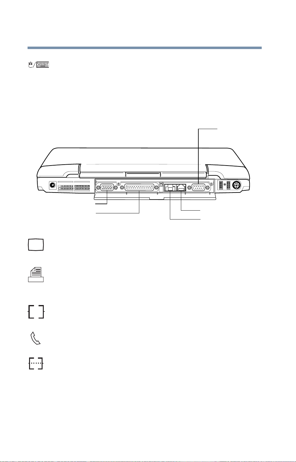
Back with rear panel open
Serial port
Ether
RGB port
Parallel port
Network port
Modem port
RGB port—Lets you connect an external monitor or projector.
Parallel port—Lets you connect a parallel printer or other parallel
device.
The Network port (RJ45 jack) provides access to a LAN via
®
standard Ethernet
network cable.
Modem port—Lets you connect the computer’ s internal modem
directly to a conventional telephone line.
Serial port—Lets you connect a serial mouse, serial printer , or
other serial device.
Page 31

Right side
Speaker—Lets you hear stereo sound from a CD or DVD in
addition to system alarms and audible warnings associated with
your software.
Left side
Making sure you have e verything
HDD bay cover
Finding Your Way Around
31
Speaker
Speaker
Video-out port
Slim SelectBay module
(DVD-ROM drive shown)
PC Card ejection buttons
PC Card slots
PC Card lock
Security lock slot
* for systems with optional Wi-Fi™ or Bluetooth
SD Media card slot
W-Fi™/Bluetooth
power switch*
™
™
Speaker—Lets you hear stereo sound from a CD or DVD in
addition to system alarms and audible warnings associated with
your software.
Video- out port—Lets you connect your computer to an e xternal
video device such as a standard tele vision set.
The security lock slot allows you to attach the optional
POR T-Note worthy
®
Computer Lock cable to the computer to
secure it to a large, heavy object such as your desk.
Page 32

32
Finding Your Way Around
Making sure you have e verything
The PC Card lock allows you to secure your PC Cards in the
slots. Slide the button to the right to lock the PC C ards. This lock
mechanism can be secured in place using a computer lock. See
“Using a computer lock” on page 100.
The PC Card slots allow you to connect PCMCIA-compatible
devices to the computer . These slots can accommodate tw o T ypeI
or T ypeII PC Cards, or one Type III PC Card. For more
information, see “Inserting and removing PC Cards” on
page 73.
CAUTION: Keep foreign objects out of the PC Card slots. A
pin or similar object that accidentally gets into a slot can
damage the computer’s circuitry.
The PC Card eject buttons allow easy remo v al of PC Cards.
®
Slim SelectBay
— Lets you use one of several possible Slim
SelectBay modules. The DVD-ROM drive is shown in place. F or
more information, see “Using Slim SelectBay® modules” on
page 69.
SD Media
™
card slot—Lets you insert SD Media cards for
additional RAM or data storage.
Wi-Fi
Bluetooth systems)— Lets you turn on a Wi-Fi
™
/Bluetooth™ power switch (av ailable only on Wi-Fi or
or Bluetooth
module on your system.
Page 33

Underside
Slim SelectBay release
Slim SelectBay slot
Finding Your Way Around
Making sure you have e verything
33
Battery module
Battery lock
Memory module
cover
HDD bay cover
Expansion port
PC card lock
Battery module—Lets you to use your computer when a
standard electrical outlet is not a vailable. F or further information
about using the battery , see “Running the computer on battery
power” on page 116.
Battery lock—Locks the battery in place to prevent accidental
removal.
Slim SelectBay
secure in its compartment.
Memory module—Lets you add more memory to your
computer . For more information, see “Adding memory” on
page 64.
Slim SelectBay
which offer exceptional system fle xibility. For more information,
see “Using Slim SelectBay® modules” on page 69.
®
release—Keeps the Slim SelectBay® module
®
slot—One of several interchangeable de vices
PC Card lock—Keeps the PC Cards secure in their slots.
Page 34

Finding Your Way Around
34
Ke yboar d and display features
The expansion memory cover protects the sl ot in which you can
install up to two memory modules. For more information on
expanding your computer’s memory , see “Adding memory” on
page 64.
Keyboard and display features
Front with the display panel open
To view the front of the computer with the display panel open:
1 Locate the display latch on the front of the computer .
Releasing the display latch
2 Slide the display latch to the right and lift the display panel.
Opening the display panel
Page 35

Finding Your Way Around
Ke yboard and display features
3 Adjust the display panel to a comfortable viewing angle.
CAUTION: To avoid damaging the display panel, be careful
when opening and closing it. Never force the panel beyond
the point where it moves easily, and never use it to lift the
computer.
Screen
Keyboard
35
Speaker
Power button
CapsLock
indicator
AccuPoint II
pointing device
Power button —The power button is used to turn on po wer to the
computer . For more information, see “Different w ays to turn the
computer on and off” on page 104 .
Screen—The computer’ s screen is a liquid crystal display (LCD)
that provides clear, sharp images.
Primary
button
Secondary
button
AccuPoint II
buttons
Speaker
Keyboard
indicator panel
Programmable
buttons
System
indicator panel
Keyboard—The 85-ke y keyboa rd provides all the functionality
of a full-size keyboard. It has several b uilt-in hot-key functions that
Page 36

36
Finding Your Way Around
Ke yboar d and display features
turn system functions on and off. F or more information on how to
use the internal keyboard, see “Using the ke yboard” on page 82.
For information on using an external ke yboard, see “Connecting
external (optional) de vices” on page 166.
Keyboard indicator panel—These lights pro vide information
about various ke yboard functions. See “Keyboard indicator
panel lights” on page 37 for a description of the panel lights.
AccuPoint
function of a mouse with the conv enience of ne ver ha ving to
remove your hands from the keyboard. The AccuPoint II b uttons
(Primary and Secondary) work with the AccuPoint II pointing
device. For further information, see “Using the AccuPoint II
pointing device” on page 49.
System indicator panel—These lights provide status information
about various system functions. See the follo wing section for a
description of each panel light.
®
II pointing device—This device combines the
Indicator panel lights
This panel is located on the front of the computer.
A C power light—Glows green when the computer is connected
to an AC po wer source.
On/off light—Indicates whether the computer is on, off, or in a
Standby power do wn mode.
❖ Glows green when the computer is on.
❖ Flashes amber when you power do wn the computer using the
Standby command.
❖ May flash amber if the computer is overheating.
Page 37

Finding Your Way Around
Ke yboard and display features
Main battery light—Indicates the status of the main battery.
❖ Flashes amber when you are running on battery power and the
battery charge is running low.
❖ Does not glow when you are running on battery po wer and
the battery charge is not running low.
❖ Glows amber when you are connected to A C po wer and the
battery is charging.
❖ Glows green when you are connected to A C po wer and the
battery is fully charged.
For more information, see “Monitoring battery power” on
page 117.
Hard disk drive light—Flashes to indicate that the hard disk is
currently in use.
37
Slim SelectBay indicator light—Indicates the status of a
secondary battery in the Slim SelectBay, if installed.
❖ Glows amber when the battery is charging.
❖ Glows green when the battery is fully char ged.
❖ Does not glow if there is no battery in the Slim SelectBay.
Wireless indicator light—Glo ws to indicate that wireless device
is currently in use.
Keyboard indicator panel lights
The keyboard indicator lights provide information about k eyboard
functions.
Cursor control light—Glows when the cursor control overlay is
on. When this light is on, pressing an overlay ke y moves the cursor
as shown by the white arro w or command printed on the left front
of the key instead of the letter printed on the top of the ke y. For
more information, see “Using the overlay for cursor control”
on page 86.
Page 38

38
Finding Your Way Around
Ke yboar d and display features
Numlock light—Glows when the numeric overlay is on. When
this light is on, pressing an overlay ke y produces the white number
printed on the right front of the key instead of the letter printed on
the top of the key. For more information, see “Using the overlay
to type numeric data” on page 85.
Page 39

Chapter 2
Getting Started
This chapter provides tips for working comfortably , describes ho w
to connect components, and explains what to do the first time you
use your computer.
Selecting a place to work
Your computer is designed to be used in a v ariety of locations and
situations. This section provides guidelines for setting up your
computing environment.
Creating a computer-friendly environment
Place the computer on a flat surface that is large enough for the
computer and any other items you need to use, such as a printer.
Leave enough space around the computer and other equipment t o
give adequate v entilation, otherwise, the y may ov erheat.
To keep your computer in prime operating condition, protect your
work area from:
❖ Dust, moisture and direct sunlight
39
Page 40

40
Getting Started
Selecting a place to work
❖ Liquids and corrosive chemicals
CAUTION: If you spill liquid into the computer, turn it off,
unplug it from the AC power source and let it dry out
completely before turning it on again.
If the computer does not operate properly after you turn it
back on, contact a Toshiba service representative or your
network administrator.
❖ Equipment that generates a strong electromagnetic field, such
as large stereo speakers (other than speakers that are
connected to the computer) or speakerphones.
❖ Rapid changes in temperature or humidity and sources of
temperature change such as air conditioner vents or heaters.
❖ Extreme heat, cold, or humidity . Operate the computer within
a temperature range of 41 degrees to 95 degrees F ahrenheit
(5 degrees to 35 degrees Celsius) and 20 percent to 80 percent
non-condensing humidity .
Keeping yourself comfortable
Strain and stress injuries are becoming more common as people
spend more time using their computers. Howev er, with a little care
and proper use of the equipment, you can work comfortably
throughout the day .
WARNING: Using the computer keyboard incorrectly can
result in discomfort and possible injury. If your hands,
wrists, and/or arms hurt while typing, stop using the
computer and rest. If the discomfort persists, consult a
physician.
Page 41

Getting Started
Selecting a place to work
This section provides hints on av oiding strain and stress injuries.
For more information, consult books on ergonomics, repetiti v estrain injury , and repetiti ve-stress syndrome.
41
Placement of the computer
Proper placement of the computer and external de vices is
important to avoid stress-related injuries. Consider the following
when placing your computer.
❖ Place the computer on a flat surface at a comfortable height
and distance. You should be able to type without twisting your
torso or neck and look at the screen without slouching.
❖ If you use an external monitor , the top of the screen should be
no higher than eye lev el.
❖ If you use a paper holder, set it at the same height and distance
as the screen.
Seating and posture
When using your computer, maintain good post ure with your
body relaxed and your weight distributed ev enly. Proper seating is
a primary factor in reducing work strain. Some peopl e find a
backless chair more comfortable than a conventional chair.
Whichever type you choose, use the follo wing guidelines to adjust
your chair for maximum computing comfort.
Page 42

42
Below eye level
Footrest
Getting Started
Selecting a place to work
Approximately
90° angles
Correct posture and positioning of the computer
❖ Position your chair so that the keyboard is at or slightly lo wer
than the level of your elbo w. You should be able to type
comfortably with your shoulders relaxed and your forearms
parallel to the floor .
If you are using a conventional chair:
❖ Your knees should be slightly higher than your hips. If
necessary , use a foot rest to raise the le vel of your knees and
ease the pressure on the back of your thighs.
❖ Adjust the back of your chair so that it supports the lower
curve of your spine. If necessary, use a cushion to provide
extra back support. Lower -back-support cushions are
availa ble at many of f ice supply stores.
❖ Sit with your back straight so that your knees, hips, and
elbows form approximately 90-degree angles when you w ork.
Do not slump forward or lean back too far .
Lighting
Proper lighting can improve the readability of the display and
reduce eyestrain.
Page 43

Getting Started
Other precautions
❖ Position the display panel or external monitor so that sunlight
or bright indoor lighting does not reflect off the screen. Use
tinted windows or shades to reduce glare.
❖ A v oid placing your computer in front of a bright light that
shines directly into your eyes.
❖ If possible, use soft, indirect lighting in your computer work
area.
43
Arms and wrists
❖ A void bending, arching, or twisting your wrists. K eep them in
a relaxed, neutral position while typi ng.
❖ Exercise your hands, wrists and arms to improv e circulation.
Work habits
The key to av oiding discomfort or injury from strain is to v ary
your activities. If possible, schedule a varie ty of tasks into your
working day . Finding w ays to break up the routine can reduce
stress and improve your ef ficienc y.
❖ Take frequent, short breaks to change position, stretch your
muscles, and reliev e your eyes. A break of two or three
minutes every hal f hour is more effecti v e than a long break
after sev eral hours.
❖ A v oid performing repetiti ve acti vities for long periods.
Intersperse such activities with other tasks.
❖ Focusing your eyes on your computer screen fo r long periods
can cause eyestrain. Look away from the computer fre quently
and focus your eyes on a distant object for at least 30 seconds.
Other precautions
Y our computer is designed to optimize safety , minimize strain, and
withstand the rigors of portability . Ho we ver , you should observ e
Page 44

44
Getting Started
Setting up your computer
certain precautions to further reduce the risk of personal injury or
damage to the computer .
CAUTION: Do not apply heavy pressure to the computer or
subject it to sharp impacts. Excessive pressure or impact can
damage computer components or cause your computer to
malfunction.
CAUTION: Some PC Cards can become hot with prolonged
use. If two cards are installed, both can become hot even if
only one is used extensively. Overheating of a PC Card can
result in errors or instability in the PC Card operation.
Be careful when you remove a PC Card that has been used
for lengthy periods of time.
Setting up your computer
Your computer comes with a rechargeable battery pack that must
be charged before you can use it.
T o use e xternal power or to char ge the battery , you must attach the
AC adapter. See “Connecting to a power source” on page 45.
To register your computer online, or to sign up for an Internet
account, you must connect the built-in modem to a telephone line.
Before using your computer, you may w ant to:
❖ Add more memory
❖ Connect a mouse
❖ Connect a full-size keyboard
❖ Connect an external monitor
❖
Connect a local printer
Page 45

❖ Install PC Cards
❖ Connect a port replicator
T o add an y of these devices to the computer , do so before you turn
on the computer . For more information, see “Expansion
Options” on page 165.
Connecting to a power source
The AC adapter allo ws you to po wer the computer from an
external A C power source and to char ge the computer’s batteries.
Getting Started
Setting up your computer
45
AC adapter
Power cable
Power cable and AC adapter
CAUTION: Use of the wrong AC adapter could damage your
computer. Toshiba assumes no liability for any damage in
such cases.
Never pull directly on the power cable to unplug it. Hold the
power plug when removing the cable from the outlet.
To connect the computer to an external power source:
1 Connect the socket end of the power cable to the A C adapter .
Page 46

46
_
Getting Started
Setting up your computer
Connecting the power cable to the AC adapter
+
2 Connect the DC OUT end of the AC adapter cable to the
DC IN jack at the back of the computer.
Connecting the AC adapter cable to the computer
3 Insert the plug end of the power cable into a li ve w all outlet.
The AC po wer light on the system indicator panel glows
green.
If the main battery is present, the battery light glows:
❖ Amber while the battery is charging
❖ Green when the battery is fully charged
If the battery light flashes amber during charging, either the
battery pack is malfunctioning, or it is not receiving input
from the AC po wer supply. Disconnect the AC cable and
Page 47

Getting Started
T urning on the computer
remove the battery pack. See “If Something Goes Wrong”
on page 201 for troubleshooting information.
DANGER: Damaged power cables can cause fire or electric
shock. Never modify, forcibly bend, place heavy objects on
top of, or apply heat to the power cable.
If the power cable becomes damaged or the plug overheats,
discontinue use. There is a risk of electric shock.
Never remove the power plug from the outlet with wet hands.
Doing so may cause an electric shock.
47
Charging the battery
Your computer came with its battery already installed. Before
using the battery to power the computer , you must cha rge it.
To charge the battery , leav e the computer plugged in to an A C
power source for at least three hours with the computer turned of f.
After that, the battery will be completely charged and ready to
power the computer .
CAUTION: Once the battery is charged for the first time,
avoid leaving the computer plugged in and turned off for
more than a few hours at a time. Continuing to charge a fully
charged battery can damage the battery.
Turning on the computer
The computer is now ready for you to turn it on and begin using it.
Opening the display panel
1 Slide the display latch to the right.
Page 48

Getting Started
48
T urning on the computer
2 Lift the display panel.
CAUTION: To avoid damaging the display panel, do not force
it beyond the point where it moves easily, and never lift the
computer by the display panel.
Turning on the power
T o turn on the computer:
1 Make sure any external de vices (such as the A C adapter, if
you plan to use AC po wer rather than battery po wer) are
properly connected and ready .
2 Check to ensure that any floppy drives are empty.
3 Press and hold the power button in until the on/of f light on the
system indicator panel glows green—about one second.
T urning on the power
For the meaning of each light on the system indicator panel,
see “Indicator panel lights” on page 36.
Page 49

Getting Started
Using the AccuP oint II pointing device
4 The preinstalled operating system will load automatically .
CAUTION: When you turn on the computer for the first time,
don’t turn off the power again until the operating system has
loaded completely.
Using the AccuPoint II pointing device
The button in the middle of the ke yboard is the AccuPoint II
pointing device. Together with the primary and secondary
AccuPoint II buttons, it provides the same functionality as a
mouse — it enables you to move the cursor and to select items on
the screen.
49
AccuPoint II pointing device
Internet Back button
Universal scroll
Primary AccuPoint II button
Secondary AccuPoint II button
AccuPoint II pointing system
HINT: If you would rather use a mouse or trackball, you can
connect one to the computer’s serial port, USB port, or PS/2
port. For information, see “Using a mouse” on page 167.
To move the cursor , gently push the AccuPoint II pointing device
in the direction you want the cursor to mov e. Pushing harder on
the AccuPoint II pointing device mov es the cursor faster.
Page 50

50
Getting Started
Setting up your software
The primary AccuPoint II button corresponds to the primary
(typically left) mouse button. When a step instructs you to click or
choose an item, move the cursor to the item, then press and release
the primary AccuPoint II button. To double-click, press the
primary AccuPoint II button twice in rapid succession.
The secondary button acts as the second (typically right) mouse
button. The function of the secondary AccuPoint II b utton
depends on the program you are using. Check your program’s
documentation to determine whether it uses the right mouse
button. For more information on programming b uttons and ke ys,
see “Fn-esse” on page 182.
The small left button performs the Internet Back button.
The small right button performs the Uni versal scroll.
Setting up your software
The first time you turn on your computer , the W i ndo ws® XP
Professional operating system guides you through several essential
steps to set up your software. These steps may or may not appear
in the this order:
❖ Select your time zone.
Select one of the time zones listed by clicking the up and
down arro w keys to highlight the appropriate ti me zone, then
click Next to change the setting.
❖ Confirm acceptance of the Microsoft
Agreement and complete information about the operating
system.
®
End User License
Page 51

Getting Started
Setting up your software
❖ You may be offered the opportunity to register your computer
with Toshiba. If not, make sure you register later .
NOTE: To register online, your computer’s modem must be
connected to a voice-grade telephone line, or the Internet via
a Local Area Network.
❖ To register your computer at a later time, select No, I do not
want to register at this time.
NOTE: If you select to register at a later time, a reminder
dialog box will appear after each startup until you register
your product.
51
❖ Read about Warranty Extensions and Upgrades.
This step provides important information from Microsoft
❖ Sign up for Internet access.
This step guides you through signing up for a new Internet
account, or assists you in setting up your computer to work
with your existing Internet account.
Completing installation
Upon completion, you will be prompted to click Finish to restart
your computer.
Setting up other devices
You may want to take this time to set up your printer. For more
information, see “Setting up your printer” on page 171.
®
.
Page 52

Getting Started
52
T urning off the computer
Turning off the computer
It’ s generally a good idea to turn of f your computer when you are
not using it.
If you are using the computer for the first time, leav e the computer
plugged into a power source (e ven though the computer is of f) to
fully charge the main battery. With the computer of f, it may take
up to three hours to recharge the main battery.
Guidelines for turning off the computer:
❖ If you have work in progre ss and are not connected to a
network, use the W indo ws
system settings to memory so that, when you turn on the
computer again, you will automatically return to where you
left off.
❖ To leave the computer off for a longe r period, use the
Windows
Hibernation mode to save the system settings to the hard disk.
For more information, see “Powering down the computer”
on page 105.
CAUTION: Never turn off the computer while any drive is in
use. Doing so may damage the media in use and result in
loss of data.
®
Turn Of f Computer command. Alternati v ely, use
Closing the display panel
®
Standby command to sav e your
When you are finished, shut the computer down a nd close the
display panel to keep dust and dirt out of the computer.
If you close the computer while it is still on, these actions will
occur:
❖ If you have the LCD po wer -sav er feature set, the LCD panel
will automatically turn off until you open it again .
Page 53

Getting Started
T urning of f the computer
❖ If you have the audible w arning set, the computer will beep to
notify you that it is still on.
❖ If you have an action feature set, the co mputer will perform
either: Nothing, Standby, Hibernate, or Turn Off (see
“Enabling Hibernation” on page 195).
53
Page 54

54
Getting Started
T urning off the computer
- Blank Page -
Page 55

Chapter 3
Connecting Other
External Devices
This chapter describes how to connect de vices that can increase
the capabilities of your Satellite Pro
®
6000 Series computer .
Using external display devices
Your computer comes with a built-in LCD display, but you can
also connect three different types of external display devices to
one of two av ailable video ports:
❖ A television via the video-out (composite) port.
❖ A video display device, such as a video projection unit, via the
video-out (composite) port.
❖ An external monitor or projector via the RGB port.
Before connecting a television, video projector , monitor or other
display device, configure your computer for the type of de vice
you’ re connecting. To do this, refer to the documentation for your
operating system and devices.
55
Page 56

Connecting Other External Devices
56
Using external display devices
Connecting the display device
If you’ re connecting a tele vision or other video display de vice to
the computer’ s video-out port, f irst refer to “Selecting video
cables” below for guidelines on choosing a video cable, then refer
to “Connecting to the video-out (composite) port” on page 56.
If you’ re connecting an SVGA monitor , skip to “Connecting an
external monitor or projector” on page 57.
Selecting video cables
To connect a device to the video-out port, you need to purchase a
composite video cable. For the best video quality, always use a
properly shielded cable.
HINT: Toshiba recommends using a cable no longer than
20 feet (approximately 6 meters).
Using a poor quality cable may result in a dull or fuzzy picture,
poor color, ghosting, vide o noise, or loss of video.
Connecting to the video-out (composite) port
To connect the device:
1 Connect one end of the video cable to the external video
device.
Refer to the documentation provided with the device for the
location of its video-in port.
2 Connect the other end of the video cable to the plug on the
video port adapter (included with your computer), and
connect the other end of the video port adapter cable to the
video-out port on the left side of the computer.
3 Turn on the external video de vice.
Page 57

Connecting Other External Devices
Using external display devices
57
4 Set the display mode by pressing
Display Properties settings. For more information, see
“Directing the display output when you turn on the
computer” on page 57.
Fn + F5, or by setting the
Connecting an external monitor or projector
You can easily attach an external monitor or projector to your
computer if you need a larger screen. To do this:
1 Connect the monitor’ s video cable to the RGB port on the
back of the computer .
2 Connect the device’s power cable to a live electrical outlet.
3 Turn on the e xternal de vice.
4 Set the display mode by pressing
Display Properties settings. For more information, see
“Directing the display output when you turn on the
computer” on page 57.
Fn + F5, or by setting the
Directing the display output when you turn on the computer
Once you’ ve connected an external display device, you can choose
to use the internal display only, the e xternal de vice only, or both
simultaneously . The quick est way to change the display output
settings is to use the display hot key (
1 Press
2 While holding down
you want takes effect.
This hot key cycles through the settings in the follo wing
order:
❖ Built-in display only
❖ Built-in display and external device simultaneously
❖ External device only
Fn and F5 simultaneously .
Fn, press F5 repeatedly until the setting
Fn + F5):
Page 58

58
Connecting Other External Devices
Using external display devices
❖ TV (or other external video de vice) only
3 Release the
TECHNICAL NOTE: You can also change these settings
using the Display Properties Box.
For more information on switching the display output, see
“Connecting the display device” on page 175.
Fn key .
Adjusting the quality of the external display
To obtain the best picture quality from your television (or other
video display device), you may need to adjust the video settings.
See the video device documentation for additional conf iguration
steps.
TECHNICAL NOTE: In order to use one of the simultaneous
modes, you must set the resolution of the internal display
panel to match the resolution of the external display device.
The external display device must support a resolution of
640 X 480 or higher.
Video limitations
Keep in mind that the quality of the display will be limited to the
capabilities of the external video device.
❖ If the external video de vice, such as an SVGA monitor , is
capable of displaying at a maximum resolution of 640 x 480
and your system is set for a higher resolution, only part of the
desktop will appear on the screen. You can view the “lost”
area by scrolling to it.
❖ Since most televisions and vi deo projectors ov erscan by 15 to
20 percent, some of the desktop will be outside the viewing
area. You can view the edge of the desktop b y scrolling to it.
Page 59

Connecting Other External Devices
Using an external ke yboar d
❖ If you use the display hot key (Fn + F5) to change the display
output with the LCD Display Stretch option enabled and the
display area (resolution) set to 640 x 480 or 800 x 600, the
image on the internal display panel may appear stretched.
Using an external keyboard
If you prefer to use a full-size keyboard, you can attach one to your
computer . The computer’ s PS/2 port supports a ny PS/2compatible keyboard.
NOTE: If you connect a PS/2 keyboard to the computer while
it is in Standby mode, you will not be able to use the
keyboard when you turn the computer on.
59
CAUTION: When connecting any PS/2 device, turn off your
computer to prevent any possible hardware damage.
HINT: You can only connect one PS/2 device at a time,
unless you purchase an optional Y-cable. Connecting a
Y-cable to the computer’s PS/2 port allows you to connect
a PS/2-compatible mouse and a PS/2-compatible keyboard
simultaneously.
Making your external keyboard emulate the Fn key
An external keyboard does not ha v e the Fn ke y contained on the
Satellite Pro
the computer’ s hot ke ys or hav e set up key combinations in
Fn-esse
external keyboard. Don’ t worry: you can use a key combination on
the external keyboard to emulate the
®
6000 Series computer’ s built-in keyboard. If you use
®
, you’ll probably miss these features when using an
Fn key . You can set up this
Page 60

Connecting Other External Devices
60
Using a mouse
key combination through the W indo ws Control P anel Toshiba
HWSetup icon. For more information about Hardware Setup, see
“Toshiba Hardware Setup” on page 193.
NOTE: The Control Panel window must be set to Classic
View to access the Toshiba HWSetup icon.
Using a mouse
You may want to use a mouse instead of the computer’ s b uilt-in
pointing device, the AccuPoint II. You can use a serial mouse or a
PS/2-compatible mouse.
A serial mouse disables the AccuPoint II. A PS/2-compatible
mouse allows you to hav e the AccuPoint II active at the same time.
Setting up a PS/2 mouse with the AccuPoint II
When you connect a PS/2-compatible mouse to the PS/2 port, you
may use the mouse, the AccuPoint II, or both.
CAUTION: When connecting any PS/2 device, turn off your
computer to prevent any possible hardware damage.
NOTE: If you connect a PS/2 mouse to the computer while it
is in Standby mode, you will not be able to use the mouse
when you turn the computer on.
To set the PS/2 mouse to work simultaneously with the
AccuPoint II:
1 Click Start, Settings, then point to Control P anel.
Page 61

Connecting Other External Devices
Connecting a local printer
2 Double-click the Toshiba HWSetup icon.
3 Select the Pointing Devices tab, then click Simultaneous.
Connecting a local printer
CAUTION: Never connect the printer cable while the
computer’s power is on. Doing so may damage the printer,
the computer, or both.
Before you can connect a printer, you need to kno w whether it
uses a serial or a parallel interface. Check the printer’ s
documentation. If the printer can be switched between serial and
parallel mode, choose parallel because it is faster .
61
You also need a suitable printer cable, which may come with your
printer . Otherwise, you can purchase one from a computer or
electronics store.
NOTE: If your printer is ECP- or IEEE-compliant, make sure
your printer cable is an IEEE 1284 cable.
These instructions assume you have a parallel printer , which is the
most common type of interface.
To connect the printer:
1 If the computer is on, turn it off.
2 Connect the printer cable to the printer and to the computer’ s
parallel port. Use the printer cable illustration as a connection
guide.
Page 62

Connecting Other External Devices
62
Connecting an external diskette drive
To the computer To the printer
Identifying the ends of a parallel printer cable
3 Plug the printer’ s po wer cable into a liv e electrical outlet.
4 See your printer documentation for additional configuration
steps.
For more information on getting your printer to print, see
“Printing your work” on page 92.
Connecting an external diskette drive
Some operations, such as creating a password service diskette,
require a diskette driv e designed for use with 3.5-inch disket tes.
An external USB diskette drive
To connect an optional external USB diskette driv e, connect the
cable to one of the USB ports.
Page 63

Connecting Other External Devices
Connecting external speaker s or headphones
Connecting an optional external USB diskette dri ve
63
Connecting external speakers or headphones
To attach an external stereo output device:
1 Locate the headphone jack on the front of the computer .
2 Using any necessary adapters, plug the cable from the
external audio device into the headphone jack. The
headphone jack requires a 3.5 mm 16-ohm stereo jack.
When the headphone is inserted, the internal speakers are
automatically disabled.
For more information on using headphones or external speak ers,
see “Using a compact disc drive” on page 93.
Connecting a microphone
To record high-quality sounds, you can attach a microphone:
1 Locate the microphone jack on the front of the computer.
2 Plug the microphone cord into the microphone jack.
3 T urn on the microphone.
For more information, see “Recording sounds” on page 142.
Page 64

Connecting Other External Devices
64
Using an expansion device
Using an expansion device
The expansion port allo ws you to connect your computer to an
expansion device, whic h is an excellent in v estment if you’ re using
your computer both in and out of the offi ce.
When you return to your desk, you probably want to connect to
your network, print reports from your computer , or use a mouse
instead of the AccuPoint II. Connecting cables for each of these
devices e very time you return to the of fice is time-consuming and
inconv enient.
With an e xpansion de vice, you can lea ve e xternal de vices
connected while you are using your computer away from your
desk. When you return, you can quickly connect your computer
and have immediate access to all the de vices.
T o shiba offers the follo wing e xpansion devices for the Satellite
®
Pro
6000 Series:
❖ Advanced Port Replicator
For more information, see the documentation that comes with the
device.
To purchase a docking solution, see the accessories information
packaged with your system or visit
Adding memory
HINT: To purchase additional memory modules, see the
accessories information packaged with your system or visit
toshibaaccessories.com.
Your Satellite Pro
MHz Front Side Bus (FSB) DDRAM memory module. The two
memory slots in this computer provide various memory
configurations. When additional memory is added, or original
toshibaaccessories.com.
®
6000 Series computer is equipped with a 133
Page 65

memory replaced, it is recommended that you use only compatible
133 MHz memory . In the e vent original memory is replaced with
inv alid memory, such as 66 MHz, the system will beep and will
not boot beyond the BIOS memory check. A message may
display . If this occurs, remo ve the in v alid memory and return your
machine back to its original configuration, or contact Toshiba’ s
support center at (800) 457-7777 for additional help.
Since your computer was built to order, it should have enough
memory to run your current applications. Ho we v er , if your
requirements change, you can install extra memory up to a
maximum of 512 MB.
Memory module sizes
Additional memory is easy to install. Memory modules come in
the following sizes:
Connecting Other External Devices
Adding memory
65
❖ 128 MB PC133 DDRAM
❖ 256 MB PC133 DDRAM
❖ 512 MB PC133 DDRAM
The computer has two memory expansion slots. The follow ing
table shows the possible memory configurations:
Memory Module Size
Total Memory
128 MB 128 MB none
256 MB 256 MB none
384 MB 256 MB 128 MB
512 MB 256 MB 256 MB
(slot A)
128 MB 128 MB
128 MB 256 MB
Memory Module Size
(slot B)
Page 66

Connecting Other External Devices
66
Adding memory
Installing a memory module
Additional memory modules can be installed in the memory
expansion slots on the base of the computer . You will need a
standard Phillips no.1 screwdri ver for this p rocedure.
CAUTION: To avoid damaging the computer’s screws, use a
standard Phillips no. 1 screwdriver that is in good condition.
The computer has two memory expansion slots—Slot A and
Slot B. You can install one or two memory modules.
1 Shut down your computer completely using the Shut Down
command. See “Powering down the computer” on
page 105.
2 Unplug the computer .
CAUTION: Installing a memory module with the computer’s
power on may damage the computer, the module, or both.
3 Close the display panel and remove an y cables you may ha ve
connected.
4 Turn the computer upsi de down.
Page 67

Connecting Other External Devices
Adding memory
5 Locate and remove the scre ws that hold the cov er plate in
place, and lift the cover of f of the memory module bay.
Removing the memory module cover
67
CAUTION: Static electricity can damage the memory module.
Before you handle the module, touch a grounded metal
surface to discharge any static electricity you may have built
up.
To avoid damaging the memory module, be careful not to
touch its pin connector on the side you insert into the
computer.
6 Remove the ne w memory module from its antistatic
packaging.
7 Insert the memory module in the slot and gently press it down
into place.
The clips on either side of the module will click to secure the
module.
Page 68

68
Connecting Other External Devices
Adding memory
Inserting the memory module into the slot
8 Replace the cover plate and the scre ws.
9 Turn the computer o ver and restart it.
When you turn on the computer , it automatically recognizes
the additional memory .
Removing a memory module
If you need to remove a memory module:
1 Complete steps 1–6 in “Installing a memory module” to shut
down the computer and open the memory module cov er.
2 Pull the clips away from the memory module.
The memory module pops partially out of the slot.
Page 69

Connecting Other External Devices
Using Slim SelectBay® modules
69
Pulling the clips away fr om the memory module
3 Carefully remove t he module from the slot.
4 Replace the cover plate and scre ws.
5 Turn the computer o ver and restart it.
Using Slim SelectBay® modules
The Slim SelectBay giv es you additional flexibility. By inserting
and removing Slim SelectBay modules, you can configure your
computer for the task at hand without having to carry unnecessary
components with you when you travel. For e xample, any one of
several modules can be used in the Slim SelectBay:
❖ CD-ROM dri ve
❖ DVD-ROM drive. The D VD-ROM drive can also be used as
a standard CD-ROM dri ve
❖ CD-R W driv e. A writable/re writable dri ve.
Page 70

70
Connecting Other External Devices
Using Slim SelectBay® modules
❖ CD-R W/D VD combo dri ve with both CD-RW and DVD
drive.
❖ Secondary battery
❖ Secondary hard disk driv e (HDD)
HINT: Items from this list that did not come with your
computer can be purchased separately. See the accessories
information packaged with your system or visit
toshibaaccessories.com.
Removing a module from the Slim SelectBay
1 Slide the Slim SelectBay ejection bar towards the front of the
computer .
Unlatching the Slim SelectBay
2 Slide the module out of the computer .
®
®
Page 71

Connecting Other External Devices
Inserting and removing hard drives
Sliding the module out
If you are removing the weight sav er , retain it for transporting
the computer when no other module is installed in the
Slim SelectBay.
71
Inserting a module into the Slim SelectBay
To install a module into the Slim SelectBay , simply slide the
module all the way into the Slim SelectBay .
®
Inserting and removing hard drives
Your Satellite Pro® 6000 can use 20GB, 30GB, and 40GB hard
drives. Depending upon the original hard driv e installed in your
computer, you may wish to increase storage capacity by changing
the internal drive, or you can also add additional hard dri v e space
by inserting a driv e into the select bay module.
To change the internal hard drive.
1 Shut down your computer completely using the Shut Do wn
command. See “Powering down the computer” on
page 105.
2 Unplug the computer .
3 Close the display panel and remove an y cables you may ha ve
connected.
Page 72

72
Connecting Other External Devices
Inserting and removing hard drives
4 Turn the computer upsi de down.
5 Remove the scre w on the hard dri ve ba y cov er .
Removing the hard driv e cover scr e w
6 Lift the hard drive bay co ver to e xpose the hard dri ve.
7 Grasp the plastic tab on the exposed edge of the hard drive
and pull it to remove the hard dri ve from the computer.
Removing the hard driv e fr om the computer
8 Install the new hard dri ve b y sliding it into the hard dri ve bay
and pressing it firmly until it locks. Do not force the driv e into
the computer.
Page 73

Connecting Other External Devices
Inserting and removing PC Car ds
Inserting the new har d disk drive
9 Replace the hard drive bay cov er and tighten the scre w
removed in step 5 above.
73
Inserting and removing PC Cards
Your Satellite Pro® Series computer comes with two stacked PC
Card slots and supports three types o f PC Cards:
❖ T ypeI cards—Y ou can install up to tw o of these cards, one in
each slot.
❖ T ype II cards—Y ou ca n install up to two of these cards, one in
each slot.
❖ Type III cards—You can install just one of these cards.
Inserting a PC Card
Before you insert a PC Card, refer to the documentation that
comes with the card to see if you need to do anything before you
insert it.
To insert a PC Card:
1 Locate the PC Card slot on the left side of the computer.
Page 74

74
Connecting Other External Devices
Inserting and removing PC Car ds
2 If the PC Card slots are locked, unlock them by turning the
computer over , locating the PC Card lock, removing the
retaining screw, sliding the lock into the unlocked position,
and replacing the screw.
3 Insert the PC Card.
If you have a Type III card, insert it into the lower pa rt of the
slot. If you have a Type I or Type II card, insert it into either
the upper or lower part of the slot.
Inserting a PC Card
4 When the card is almost all the way into the slot, push firmly,
but gently, to ensure a firm connection with the computer . Do
not force the card into position.
5 To lock the PC Card in its slot, turn the computer over and
locate the PC Card lock, remove the retaining scre w, slide the
lock into the locked position, and replace the screw.
Page 75

Locking the PC Car d
Removing a PC Card
Connecting Other External Devices
Inserting and removing PC Car ds
75
1 If the PC Card slots are locked, unlock them by turning the
computer over , locatin g the PC Card l ock and sliding it into
the unlocked position
2 Locate the PC Card ejection button that corresponds to the
slot in which your PC Card is installed.
The top tab releases a card in the upper slot. The bottom tab
releases a card in the lower slot.
3 Press the PC Card eject button once to extend it, and push it in
to remove the PC Card.
Page 76

76
Connecting Other External Devices
Using Secure Digital car d s
Press the PC car d ejection b utton once to extend it
The PC Card ejects slightly from the slot.
4 Grasp the edges of the PC Card and slide it out of the slot.
Inserting and removing Bluetooth™ modules
Your system may come with an optional Bluetooth module. If you
wish to insert or remove a Bluetooth module contact a Toshiba
Wireless Authorized Service Prov ider .
Setting up a PC Card for your computer
Some PC Cards are ready to use as soon as you install them.
Others, such as hard disk cards, network cards and SCSI adapters,
may need to be set up to work with your computer . To set up your
PC Card, refer to the documentation that came with the card or
refer to your operating system manual or online help.
Using Secure Digital cards
Your computer supports the use of Secure Digital (SD Media™)
memory/input/output cards. The cards can be used with a variety
of digital products: digital music players, cellular phones, PDAs,
digital cameras, digital video camcorders, etc.
Page 77

Connecting Other External Devices
Inserting an SD Media™ card
To insert an SD Media card:
1 Turn the card so that the contacts (metal areas) are f ace do wn.
2 Push the card into the slot until it locks in place.
Using Secure Digital car ds
77
CAUTION: Do not touch the SD Media™ connector (metal
area). You could expose the storage area to static electricity,
which can destroy data.
Do not remove an SD Media
written or read. Even when the message “copying...” in the
windows disappears, writing to the card might still be in
progress and your data could be destroyed. Wait for the
SD Media™ indicator light to go out.
Removing an SD Media™ card
To remove an SD Media card:
1 Right-click the Secure Digital dri ve’s icon and select Eject
from the pop-up menu.
2 Press the card inward to release it.
™
card while data is being
Page 78

Connecting Other External Devices
78
Connecting your modem to a telephone line
The card pops out slightly .
3 Lift the left side of the computer, grasp the card, and pull it
straight out.
Connecting your modem to a telephone line
Your computer comes with a built-in modem that can be
connected to a standard voice-grade telephone line.
The modem allows you to:
❖ Access the Internet.
❖ Communicate with your office’ s local area network (LAN), or
a larger corporate wide area network (WAN).
For specific information about connecting to a LAN or WAN,
consult your network administrator .
❖ Send a fax directly from your computer .
Connecting to a phone line
Before you can communicate using the modem, you need to
connect it to a telephone line. Your computer’ s b uilt-in modem
port provides an RJ11 jack, allowing you to connect the modem to
a standard voice-grade telephone line.
1 Plug one end of the telephone cable into the modem port on
the back of the computer .
Page 79

Connecting Other External Devices
Connecting your modem to a telephone line
Connecting the telephone cable to the modem port
2 Connect the other end to the RJ11 wall jack.
79
Connecting to a wall jack
CAUTION: The modem is designed for use with a standard
analog telephone line. Don’t connect the modem to a digital
telephone line. A digital line will damage the modem.
Page 80

80
Connecting Other External Devices
Connecting your modem to a telephone line
Now you’ re ready to send a f ax or use the modem to connect to an
online service or the Internet.
HINT: If you’re using a telephone line at home, disable Call
Waiting before connecting through the modem. Call Waiting
interrupts transmission.
For more information on using a modem, see “Setting up for
communications” on page 131.
Page 81

Chapter 4
Learning the Basics
This chapter gives some computing tips and provides important
information about basic features.
Computing tips
❖ Save your work frequently.
Your work stays in the computer’s temporary memory until
you save it to the disk. If the netw ork you are using goes down
and you must restart your computer to reconnect, or your
battery runs out of charge while you are working, you will
lose all work since you last saved.
See “Saving your work” on page 90 for further information.
HINT: Some programs have an automatic save feature that
can be activated. This feature saves your file to the hard disk
at preset intervals. See your software documentation for
details.
81
Page 82

82
Learning the Basics
Using the keyboard
❖ Back up your files to disks (or other remov able media) on a
regular basis. Label the backup copies clearly and store them
in a safe place.
It’ s easy to put off backing up because it t akes time. Ho wev er ,
if your hard disk suddenly fails, you will lose all the data on it
unless you have a separate backup copy.
❖ Use Error-checking and Disk Defragmenter regularly to
conserve disk space and improve performance.
❖ Scan all new files for viruses.
❖ This precaution is especially important for files you recei ve
via diskette, email, or download from the Internet. Take
frequent breaks to avoid repe titiv e-motion injuries and
eyestrain.
❖ Don’t turn off the computer if a dri v e indicator light indicates
a drive is acti v e.
Turning of f the computer while it is reading from or writing to
a disk may damage the disk, the drive, or both.
❖ Before turning off the computer , use the T urn Of f Computer
command or Standby command. See “Powering down the
computer” on page 105 to learn more about Standby.
NOTE: The Windows®XP Professional operating system
records information, such as your desktop setup, during its
shutdown procedure. If you don’t let the Windows
Professional operating system shut down normally, details
such as new icon positions may be lost.
Using the keyboard
®
XP
Your computer’ s ke yboard contains character k eys, control ke ys,
function keys, and special W indo ws
functionality of a full-size keyboard.
®
keys, providing all the
Page 83

Keyboard
Character keys
Typing with the character keys is very much lik e typing on a
typewriter , e xcept that:
Learning the Basics
Using the keyboar d
83
❖ The space bar creates a space character instead of just passing
over an area of the page.
❖ The lowercase letter l (el) and the number 1 are not
interchangeable.
❖ The uppercase letter O and the number 0 are not
interchangeable.
Making your keyboard emulate a full-size keyboard
Although your computer’ s keyboard layout is compatible with a
standard full-size keyb oard, it has fewer k eys.
A standard full-size keyboard has two
editing keys, cursor positioning ke ys, and a numeric ke ypad.
Pressing the
specially marked keys allo ws you to emulate a full-size keyboard.
Your computer’ s k e yboard has only one
Most of the time this doesn’t matter . Ho we ver , some programs
assign separate functions to the right and left
the regular and numeric pad
Using the
Fn key simultaneously in combination with one of the
Enter keys on the full-sized k eyboard.
Fn key you can simulate these separate k eys, as follo ws:
Enter, Ctrl, and Alt keys,
Enter and one Ctrl key .
Ctrl and Alt keys, or to
Page 84

Learning the Basics
84
Using the keyboard
❖ Press Fn and Ctrl simultaneously to simulate the Ctrl ke y on the
right side of the enhanced ke yboard.
❖ Press Fn and Enter simultaneously to simulate the Enter key on
the numeric pad of the enhanced keyboard.
Ctrl, Fn, and Alt keys
Ctrl
Ctrl, Fn, and Alt keys
The
Ctrl, Fn, and Alt keys do dif ferent things depending on the
program you are using. For more information, see your program
documentation.
Function keys
The function keys (not to be confused with the Fn ke y) are the 12
keys at the top of the keyboard.
The function keys
F1 through F12 are called function keys because they ex ecute
programmed functions when pressed. Used in combination with
the
Fn key, function keys marked with icons execute specif ic
functions on the computer . For more information, see “Fn-esse”
on page 182, or “Hot Keys” on page 239.
Fn
Alt
Windows special keys
The W indows special ke ys
Start key
Application key
Page 85

Your computer’ s k eyboard has two ke ys that ha ve special
functions in Windo ws:
❖ Start key—Opens the Start menu
❖ Application key—Has the same function as the secondary
mouse (or AccuPoint II) button
Overlay keys
The keys with gray numbers and symbols on the front of them
form the numeric and cursor overlay. This overlay lets you enter
numeric data or control the cursor as you would using the 10-ke y
keypad on a desktop computer’s keyboard.
Learning the Basics
Using the keyboar d
85
&
789
Home PgUp
78 9
UIOP
(
*
456
JKL
End PgDn
123
M
Ins Del
)
0
<
,
0
*
-
:
;
+
>
?
.
/
.
/
Numeric and cursor contr ol overlay
Using the overlay to type numeric data
The keys with the numbers on their right front are the numeric
overlay ke ys.
To turn the numeric overlay on, press Fn and F11 simultaneously.
The numeric mode light on the keyboard indicator panel glo ws
when the numeric overlay is on.
Page 86

86
Learning the Basics
Using the keyboard
You can still use the overlay ke ys to type alphabetic characters
while the numeric overlay is on. To do so:
❖ For lowercase letters, hold do wn Fn while you type the letters.
❖ For uppercase letters, hold down both Fn and Shift while you
type the letters.
To use the cursor control keys when the numeric overlay is on:
❖ Press and hold down Shift while you use the cursor control
overlay keys.
❖ To return to the numeric overlay , release Shift.
T o disable the numeric ov erlay , hold down the
again. The numeric mode light on the keyboard indicator panel
goes out.
Fn key and press F11
Using the overlay for cursor control
The keys with the gray arro ws and symbols on their left front are
the cursor control overlay ke ys.
T o turn the cursor control ov erlay on, press Fn and F10
simultaneously . The cursor control mode light on the ke yboard
indicator panel glows when the cursor control overlay is on.
To type alphabetic characters while the overlay is on:
❖ For lowercase letters, hold do wn Fn while you type the letters.
❖ For uppercase letters, hold down both Fn and Shift while you
type the letters.
T o use the numeric overlay k eys while the cursor control overlay is
on:
❖ Hold down Shift while you use the numeric overlay k eys.
❖ To return to the cursor control overlay, release Shift.
Page 87

Learning the Basics
Starting a pro gram
87
To disable the cursor control overlay, hold down the
press
F10 again. The cursor control mode light on the keyboard
indicator panel goes out.
Starting a program
The easiest way to start a program is to double-click the name of
the file that contains the information you want to work on. To find
the file, use My Computer or Windo ws
If you prefer to open the program first, you ha ve four options. You
can:
❖ Double-click the icon for the program on your desktop
❖ Use the Start menu
❖ Use Windo ws
program file
®
Fn key and
®
Explorer .
Explorer or My Computer to locate the
❖ Use the Run dialog box
The next three sections explain ho w to start a program from the
Start menu, Explorer and the Run dialog box.
Starting a program from the Start menu
When you install a program, the operating system usually puts an
icon in the All Programs menu. T o start a program that has an icon
in the All Programs menu, follow these steps, which use the
Windo ws
1 Click Start, then point to All Progr ams.
2 Point to the program group, in this example, Accessories.
®
Wordpad program as an example:
The Windo ws
the All Programs menu, which lists programs and program
groups. If your program is listed, go to Step 3, otherwise,
continue with Step 2.
®
XP Professional operating system displays
The Accessories menu is displayed.
Page 88

Learning the Basics
88
Starting a pro gram
3 Click the program, in this example, Wordpad.
Wordpad opens.
T o close the program, click the Close b utton in the upper right corner of the program’s windo w.
Starting a program from Windows® Explorer
If a program is not listed in the Programs menu, you can start it
from Windo ws
of your computer’ s contents as a hierarchy or “tree.” You can
easily see the content of each drive and folder on your computer.
T o use this method, you should kno w the file name and location of
the program’ s ex ecutable file (this f ile ends with.exe).
®
Explorer . W indo ws® Explorer gives you a vie w
This example opens Wordpad using its file name, wor dpad.exe.
1 Click Start, then point to All Pr ograms.
2 Click Windows Explorer .
3 In the left part of the window, under the C: icon, double-click
the folder containing the program, in this case Program Files.
Windows
folder on the right side of the window. The left side of the
window sho ws all the folders contained within the Program
Files folder .
4 In the left part of the window, click Accessories.
Windows
folder on the right side of the window.
5 In the left part of the window, double-click Wordpad.
The operating system opens Wordpad.
®
Explorer shows the contents of the Program Files
®
Explorer shows the contents of the Accessories
To close the program, click the Close button in the upperright corner of the program’s windo w.
Page 89

Learning the Basics
Starting a pro gram
Starting a program from the Run dialog box
This example uses the Run command to start Wordpad:
1 Click Start, then click Run.
The Run dialog box appears.
Sample Run dialog box
89
2 In the Run dialog box:
❖ If you know the program’s location, type the command
line. For a program in the Windo ws
program name. Otherwise type the full file path. For
example, to access Wordpad, type:
c:\Program Files\Accessories\Wordpad, then click OK.
❖ If you don’t know the location, click Br o wse....
In the Browse dialog box, enter the f ile name (for
example wor dpad.e xe) and select the driv e to search.
When the operating system has found the file, click
Open.
HINT: To run the same program again, click the arrow to the
right of the text box and select the command line from the
drop-down list.
®
folder, type just the
Page 90

Learning the Basics
90
Saving your work
Saving your work
Before you turn off the computer , sav e your work on the hard disk
drive or a diskette. This is one of the most important rules of
computing.
TECHNICAL NOTE: Save your data even when you are using
the Standby command, in case the main battery discharges
before you return to work.
Saving documents is quick and easy, so it is a good idea to get in
the habit of saving frequently.
Many programs offer a feature that sav es documents at regular
intervals. Check your program’ s documentation to see if it has an
automatic save feature.
Saving files
1 On the File menu of your W indow s® program, click Save.
If you are working with a document that already has a file
name, that’ s all there is to it. If you created a ne w document,
your program displays a Save As dialog box.
Use this dialog box to specify where to store the document
and to give it a f ile name.
Page 91

Learning the Basics
Saving your work
A sample Save As dialog box
2 Choose the drive and folder where you want your file to be
stored.
91
3 Type a file name, then click Save.
HINT: To make another copy of the file you are currently
working with, choose Save As from the File menu and give
the new file a different name.
®
The Windo ws
file names of up to 255 characters; the names can include
spaces. Some applications still require MS-DOS
XP Professional operating system supports
®
file names.
File names
If you plan to share your files with a computer using a preWindo ws
name must be no more than eight characters long. T ypically the
file name also has an extension, consisting of a period and up to
three additional characters.
®
95 version of the W indo ws® operating system, the file
You may use all the letters and numbers on the keyboard plus
these characters: _,^,$,~,!,#,%,&,{,},(,),@ and ‘. MS-DOS
names are not case-sensitive and must not contain spaces.
®
file
Page 92

Learning the Basics
92
Printing your work
Using a file extension
Most programs assign an extension to the file name that identifies
the file as being created in the program with a particular format.
For example, Microsoft
Any file name with an e xtension of “.doc” is assumed to be a
Microsoft
unwise, since the program is unlikely to recognize a strange
extension and may refuse to handle your file correctly.
®
Word file. Creating your own extension is usually
Printing your work
Ensure the operating system is set up for your printer as described
in “Using a printer” on page 170.
®
Word saves files with a .doc extension.
HINT: You only need to set up the printer the first time you
connect it. If you use more than one printer or are changing
printers, you will need to set up the Windows®XP
Professional operating system to run with the additional
printer(s).
To print a file:
1 If your printer is not on, turn it on now.
2 Open the File menu of your Windo ws
Print.
The program displays a Print dialog box.
®
program and click
Page 93

A sample Print dialog box
Learning the Basics
Using a compact disc drive
93
3 Specify the print parameters. For example, the range of pages
and number of copies to print.
4 Click Print.
Using a compact disc drive
Your Satellite Pro® 6000 Series computer may have a CD-R OM,
CD-R W, D VD-R OM, or D VD/CD-RW drive.
If a CD-ROM or D VD-R OM dri ve is not currently installed in the
Slim SelectBay, follo w the instructions in “Using Slim
SelectBay® modules” on page 69.
HINT: Your DVD-ROM drive is designed to play Region 1
(North America) DVD-ROMs.
Page 94

94
Learning the Basics
Using a compact disc drive
Drive in-use indicator light
Eject button
Manual eject hole
A DVD/CD-R OM drive
Drive in-use indicator light—Indicates when the CD-R OM or
DVD-ROM drive is in use.
Eject button—Press to release the disc tray.
CAUTION: Do not press the eject button or turn off the
computer while the Drive in-use indicator light is glowing.
Doing so could damage the disc or the drive.
When the disc tray is open, be careful not to touch the lens
or the area around it. Doing so could cause the drive to
malfunction.
Manual eject hole—Use if you need to release the disc tray when
the power is of f. Use a straightened paper clip or other narrow
object to press the manual eject button located inside the hole.
CAUTION: Never use a pencil to press the eject button.
Pencil lead can break off inside the computer and damage it.
Inserting compact discs
To insert a compact disc into the DVD-R OM or CD-R OM dri v e:
1 Make sure the computer is turned on.
2 Make sure the in-use indicator light is off.
3 Press the DVD-R OM or CD-ROM drive’ s eject b utton.
Page 95

Learning the Basics
Using a compact disc drive
The disc tray slides partially out of the drive (about 1 inch).
HINT: The drive won’t open if the computer’s power is off.
4 Grasp the tray and pull it fully open.
95
The drive tray fully extended
5 Hold the disc by its edges and check that it is free of dust.
If the disc is dusty , clean it as described in “Caring for CDs
and DVDs” on page 97.
6 Place the disc carefully in the di sc tray, label side up.
Positioning the disc in the drive
Page 96

96
Learning the Basics
Using a compact disc drive
7 Gently press the disc onto the center spindle until you feel it
click into place.
CAUTION: Handle DVDs and CDs carefully, making contact
only with the center hole and edge. Don’t touch the surface of
the disc. Don’t stack discs. If you incorrectly handle the
discs, you could lose data.
8 Make sure the disc is completely on the spindle and is lying
flat on the tray .
CAUTION: If you insert the disc incorrectly, it may jam the
drive. If this happens, contact your Toshiba support for
assistance.
9 Push the disc tray in by pressing gently on the center of the
tray until it clicks into place.
You are ready to use the disc.
Removing compact discs
T o remov e a compact disc (CD or DVD) with the computer turned
on:
1 Press the eject button on the driv e.
CAUTION: Do not press the eject button while the in-use
indicator light is glowing. Doing so could damage the disc
or the drive.
Also, if the disc is still spinning when you open the disc tray,
wait for it to stop spinning before you remove it.
2 Pull the tray until it is fully open, remove the disc, and place it
in its protective co ver.
Page 97

3 Gently push the tray in to close it.
To remove a compact disc with the computer turned off:
1 Insert a slender object, such as a straightened paper clip, into
the manual eject hole.
2 Gently pull the tray out until it is fully open, remove the disc,
and place it in its protective cov er.
3 Gently push the tray in to close it.
Caring for CDs and DVDs
❖ Store your discs in their original containers to protect them
from scratches and keep them clean.
❖ Do not bend a disc or place heavy objects on top of it.
Learning the Basics
Using a compact disc drive
97
❖ Do not apply a label to, or otherwise mar the surface of a disc.
❖ Hold a disc by its outside edge. Fingerprints on the surface
can prevent the D VD-ROM drive from reading the data
properly .
❖ Do not expose discs to direct sunlight or extreme heat or cold.
❖ T o clean a disc that is dirty , wipe it with a clean, dry cloth. The
most efficient method to clean it is to start from the center of
the disc and wipe toward the outw ard edge (not in a circle). If
necessary , moisten the cloth with water or a neutral cleaner
(not benzine or rubbing alcohol). Let the disc dry completely
before inserting it in the drive.
Page 98

Learning the Basics
98
Using PC Cards
Using PC Cards
TECHNICAL NOTE: For PCMCIA-compatible PC Cards,
check the package to make sure they conform to the
PCMCIA 2.1 standard (or later). Other cards may work with
your computer, but are likely to be much more difficult to set
up and use.
For information on inserting or removing a PC Card, see
“Inserting and removing PC Cards” on page 73.
Hot swapping
With PC Cards, you can replace one PC Card with another while
the computer is on. This is called “hot swapping.”
Hot swapping precautions
Although you can insert a PC Card at any time, remember not to
remove a card while it is in use. Otherwise, you could lose
valuable information. For e xample:
❖ Do not remove a hard disk card while the system is accessing
it.
❖ Do not remove a network card while you are connected to a
network.
❖ Do not remove a SCSI card while any of the SCSI de vices
connected to it are operating.
Before removing a PC Card, stop it by clicking the PC Card
(PCMCIA) icon on the task bar . After the PC Card is stopped, it is
safe to remove.
Page 99

Using SD Media cards
If you do not already have a SD Media card inserted in the
computer, you may do so follo wing the procedures outlined in
“Inserting an SD Media™ card” on page 77.
Important: Do not use the Copy Disk function for SD Media
cards. In order to copy data from one SD Media card to another,
use the following procedure:
1 Format the target SD Media card in the same format as the
source SD Media card.
2 Insert the source SD Media card.
3 Create a temporary folder on the hard disk drive.
Learning the Basics
Using SD Media cards
99
4 Copy the contents of the source SD Media card into the
temporary folder you created in step 3.
5 Remove the source SD Media card.
6 Insert the target SD Media card created in step 1.
7 Copy the file contents from the temporary folder to the tar get
SD Media card.
8 Eject the target SD Media card.
Using your computer at the office
By connecting an external monitor , external full-size k eyboard ,
and a mouse, you can work with your notebook as if it were a
standard office computer.
An external monitor or projector connects to the RGB port.
An external PS/2-compatible keyboard or a PS/2 mouse connects
to the PS/2 port. An optional Y -cable lets you connect both de vices
to the port simultaneously .
Any serial device can connect to the serial port.
Page 100

Learning the Basics
100
Using a computer lock
Using a computer lock
For your own peace of mind, you may want to secure your
computer to a heavy object such as your desk. The easiest way to
do this is to purchase an optional POR T-Note worthy Compute r
Lock Cable.
PORT -Note worthy Computer Loc k Cable
To secure the computer:
1 Loop the cable through or around some part of a heavy object.
Make sure there is no way for a potential thief to slip the cable
off the object.
2 Pass the locking end through the loop.
3 Slide the PC Card lock (located underneath the PC Card slots)
to secure your PC Cards in place.
4 Insert the cable’ s locking end into the security lock slot on the
computer, then gi v e the key a quarter turn and remo ve it.
The computer is now securely locked. Also, an y device in the
PC Card slots are now secured to the computer by the locking
mechanism.
 Loading...