

Page 1

D4253386A
BU Series
Thank you for purchasing our product.
Before using this CMOS camera, please read through this instruction manual
carefully in order to use this product correctly and safely.
After reading, keep this instruction manual handy so that you can refer to,
whenever you need it.
CMOS Camera
Instruction Manual
Model
B/W Camera : BU302MG / BU505MG
Information contained in this document is subject to change without prior notice.
Copyright © 2016 TOSHIBA TELI CORPORATION, All rights reserved. http://www.toshiba-teli.co.jp/en/index.htm
Page 2

D4253386A
Contents
Contents .......................................................................................................................... 1
Safety Precautions ........................................................................................................... 2
General Handing .......................................................................................................................... 3
CASES FOR INDEMNITY (LIMITED WARRANTY) .................................................................... 5
RESTRICTION FOR USE ............................................................................................................ 6
Notes on using this product .......................................................................................................... 7
Installation ....................................................................................................................... 11
Specifications ................................................................................................................... 12
Overview ....................................................................................................................................... 12
Features ........................................................................................................................................ 12
Configuration ................................................................................................................................ 14
Connection .................................................................................................................................... 15
Connector Pin Assignment ........................................................................................................... 16
Outline Drawing ............................................................................................................................ 17
General Specifications .................................................................................................................. 18
LED status .................................................................................................................................... 20
I/O Specification ............................................................................................................................ 21
Timing Specification ...................................................................................................................... 25
Typical Spectral Response ........................................................................................................... 27
Operating Ambient Conditions ...................................................................................................... 28
Functions ................................ ................................ ................................ ......................... 30
Bootstrap Registers ...................................................................................................................... 32
DeviceControl ............................................................................................................................... 33
ImageFormatControl ..................................................................................................................... 34
Scalable ........................................................................................................................................ 35
Binning .......................................................................................................................................... 37
Decimation .................................................................................................................................... 39
Reverse ........................................................................................................................................ 41
PixelFormat ................................................................................................................................... 42
TestPattern .................................................................................................................................... 43
AcquisitionControl ......................................................................................................................... 45
ImageBuffer .................................................................................................................................. 47
TriggerControl ............................................................................................................................... 49
ExposureTime ............................................................................................................................... 53
DigitalIOControl ............................................................................................................................ 54
TimerControl ................................................................................................................................. 57
Gain .............................................................................................................................................. 59
BlackLevel .................................................................................................................................... 60
Gamma ......................................................................................................................................... 61
LUTControl ................................................................................................................................... 62
UserSetControl ............................................................................................................................. 63
EventControl ................................................................................................................................. 65
FrameSynchronization .................................................................................................................. 68
LEDIndicatorLuminance ............................................................................................................... 69
AntiGlitch / AntiChattering............................................................................................................. 70
DPCControl ................................................................................................................................... 72
SequentialShutterControl ............................................................................................................. 74
Appendix .......................................................................................................................... 77
MultiFrame and Bulk function difference ...................................................................................... 77
Warranty rules ................................................................................................................. 80
Repair .............................................................................................................................. 81
1 / 81
Copyright © 2016 TOSHIBA TELI CORPORATION, All rights reserved. http://www.toshiba-teli.co.jp/en/index.htm
Page 3
D4253386A
Safety Signs
Description
WARNING
Indicates a potentially hazardous situation that may result in death or serious
injury (*1) in the event of improper handling.
CAUTION
Indicates a potentially hazardous situation that may result in light to moderate
injuries (*2) or only in property damage (*3)in the event of improper handling.
Safety Symbols
Description
PROHIBITED
This sign indicates PROHIBITION (Do not).
The content of prohibition is shown by a picture or words beside the symbol.
MANDATORY
This sign indicates MANDATORY ACTION (You are required to do).
The content of action is shown by a picture or words beside the symbol.
Safety Precautions
Before using this product, read these safety precautions carefully. Important information is shown in this
Instruction Manual to protect users from bodily injuries and property damages, and to enable them to use the
product safely and correctly.
Please be sure to thoroughly understand the meanings of the following signs and symbols before reading
the main text that follow, and observe the instructions given herein.
[Definition of Safety Signs]
Notes *1:“Serious injury” refers to cases of loss of eyesight, wounds, burns (high or low temperature),
electric shock, broken bones, poisoning, etc., which leave after-effects or which require
hospitalization or a long period of outpatient treatment of cure.
*2: "Light to moderate injuries" refers to injuries, burns, electric shock etc. that do not require
hospitalization or long-term treatment.
*3: "Property damage" refers to cases of extensive damage involving damage to buildings,
equipment, farm animals, pet animals and other belongings.
[Explanation of Safety Symbols]
Copyright © 2016 TOSHIBA TELI CORPORATION, All rights reserved. http://www.toshiba-teli.co.jp/en/index.htm
2 / 81
Page 4
D4253386A
WARNING
Stop operation immediately when any abnormality or defect occurs.
If abnormal conditions are present, such as smoke, a burning smell, ingress of water or
foreign matter, or if the equipment is dropped or malfunctions, fire or electric shock may
result.
Be always sure to disconnect the power cable from the wall socket at once and contact
your dealer.
Unplug
Do not use the equipment in locations subject to water splashes.
Otherwise, fire or electric shock may result.
Do not get wet
Do not disassemble, repair, or modify the equipment.
Otherwise, fire or electric shock may result.
For internal repair, inspection, or cleaning, contact your sales representative.
Never pull apart
Do not place anything on the equipment.
If metallic objects, liquid, or other foreign matter enters the equipment, fire or electric
shock may result.
Avoid
Do not install the equipment in an unstable or inclined location or locations
subject to vibration or impact.
Otherwise, the equipment may topple over and cause personal injury.
Avoid
During an electrical storm, do not touch the power cable and the connection
cable.
Otherwise, an electric shock may result.
Do not touch
Instruction
Use the specified voltage.
Use of an unspecified voltage may result in fire or electric shock.
Do not be handled roughly, damaged, fabricated, bent forcefully, pulled, twisted,
bundled, placed under heavy objects or heated the power cable and the
connection cable.
Otherwise, fire or electric shock may result.
Avoid
General Handing
Copyright © 2016 TOSHIBA TELI CORPORATION, All rights reserved. http://www.toshiba-teli.co.jp/en/index.htm
3 / 81
Page 5
D4253386A
CAUTION
Observe the following when installing the equipment:
·Do not cover the equipment with a cloth, etc.
·Do not place the equipment in a narrow location where heat is likely to accumulate.
Otherwise, heat will accumulate inside the equipment, possibly resulting in a fire.
Instruction
Do not place the equipment in locations subject to high moisture, oil fumes,
steam, or dust.
Otherwise, fire or electric shock may result.
Avoid
Do not install the equipment in locations exposed to direct sunlight or humidity.
Otherwise, the internal temperature of the equipment will rise, which may cause a fire.
Avoid
Use only specified the power cable and the connection cables.
Otherwise, fire or electric shock may result.
Instruction
Do not give strong impact against the equipment.
It may cause the trouble.
Avoid
When performing connection, turn off power.
When connecting the power cable and the connection cable, turn off the equipment
power.
Otherwise, fire or electric shock may result.
Instruction
Do not expose its camera head to any intensive light (such as direct sunlight).
Otherwise, its inner image pickup device might get damaged.
Avoid
Avoid short-circuiting signal output.
Otherwise, a malfunction may occur.
Avoid
Avoid giving a strong shock against the camera body.
It might cause a breakdown or damage. If your camera is used in a system where its
camera connector is subjected to strong repetitive shocks, its camera connector is
possible to break down. If you intend to use your camera in such a situation, if possible,
bundle and fix a camera cable in the place near the camera, and do not transmit a
shock to the camera connector.
Avoid
Contact your sales representative to request periodic inspection and cleaning
(every approx five years).
Accumulation of dust inside the equipment may result in fire or electric shock.
For inspection and cleaning costs, contact your sales representative.
Instruction
Copyright © 2016 TOSHIBA TELI CORPORATION, All rights reserved. http://www.toshiba-teli.co.jp/en/index.htm
4 / 81
Page 6

D4253386A
CASES FOR INDEMNITY (LIMITED WARRANTY)
We shall be exempted from taking responsibility and held harmless for damage or losses incurred by the
user in the following cases.
● In the case damage or losses are caused by natural disasters, such as an earthquake and thunder, fire, or
other acts of God, acts by a third party, deliberate or accidental misuse by the user, or use under extreme
operating conditions.
● In the case of indirect, additional, consequential damages (loss of business interests, suspension of
business activities) are incurred as result of malfunction or non-function of the equipment, we shall be
exempted from responsibility for such damages.
● In the case damage or losses are caused by failure to observe the information contained in the
instructions in this instruction manual and specifications.
● In the case damage or losses are caused by use contrary to the instructions in this instruction manual and
specifications.
● In the case damage or losses are caused by malfunction or other problems resulting from unintended use
of equipment or software etc. that are not specified.
● In the case damage or losses are caused by repair or modification conducted by the customer or any
unauthorized third party (such as an unauthorized service representative).
● Expenses we bear on this product shall be limited to the individual price of the product.
● The item that is not described in specifications of this product is out of the guarantee.
● The case of damages or losses which are caused by incorrect connection of the cable is out of the
guarantee.
5 / 81
Copyright © 2016 TOSHIBA TELI CORPORATION, All rights reserved. http://www.toshiba-teli.co.jp/en/index.htm
Page 7

D4253386A
RESTRICTION FOR USE
● Should the equipment be used in the following conditions or environments, give consideration to safety
measures and inform us of such usage:
1. Use of the equipment in the conditions or environment contrary to those specified, or use outdoors.
2. Use of the equipment in applications expected to cause potential hazard to people or property, which
require special safety measures to be adopted.
● This product can be used under diverse operating conditions. Determination of applicability of equipment or
devices concerned shall be determined after analysis or testing as necessary by the designer of such
equipment or devices, or personnel related to the specifications. Such designer or personnel shall assure
the performance and safety of the equipment or devices.
● This product is not designed or manufactured to be used for control of equipment directly concerned with
human life (*1) or equipment relating to maintenance of public services/functions involving factors of safety
(*2). Therefore, the product shall not be used for such applications.
(*1): Equipment directly concerned with human life refers to.
- Medical equipment such as life-support systems, equipment for operating theaters.
- Exhaust control equipment for exhaust gases such as toxic fumes or smoke.
- Equipment mandatory to be installed by various laws and regulations such as the Fire Act or Building
Standard Law
- Equipment related to the above
(*2): Equipment relating to maintenance of public services/functions involving factors of safety refers to.
- Traffic control systems for air transportation, railways, roads, or marine transportation
- Equipment for nuclear power generation
- Equipment related to the above
6 / 81
Copyright © 2016 TOSHIBA TELI CORPORATION, All rights reserved. http://www.toshiba-teli.co.jp/en/index.htm
Page 8
D4253386A
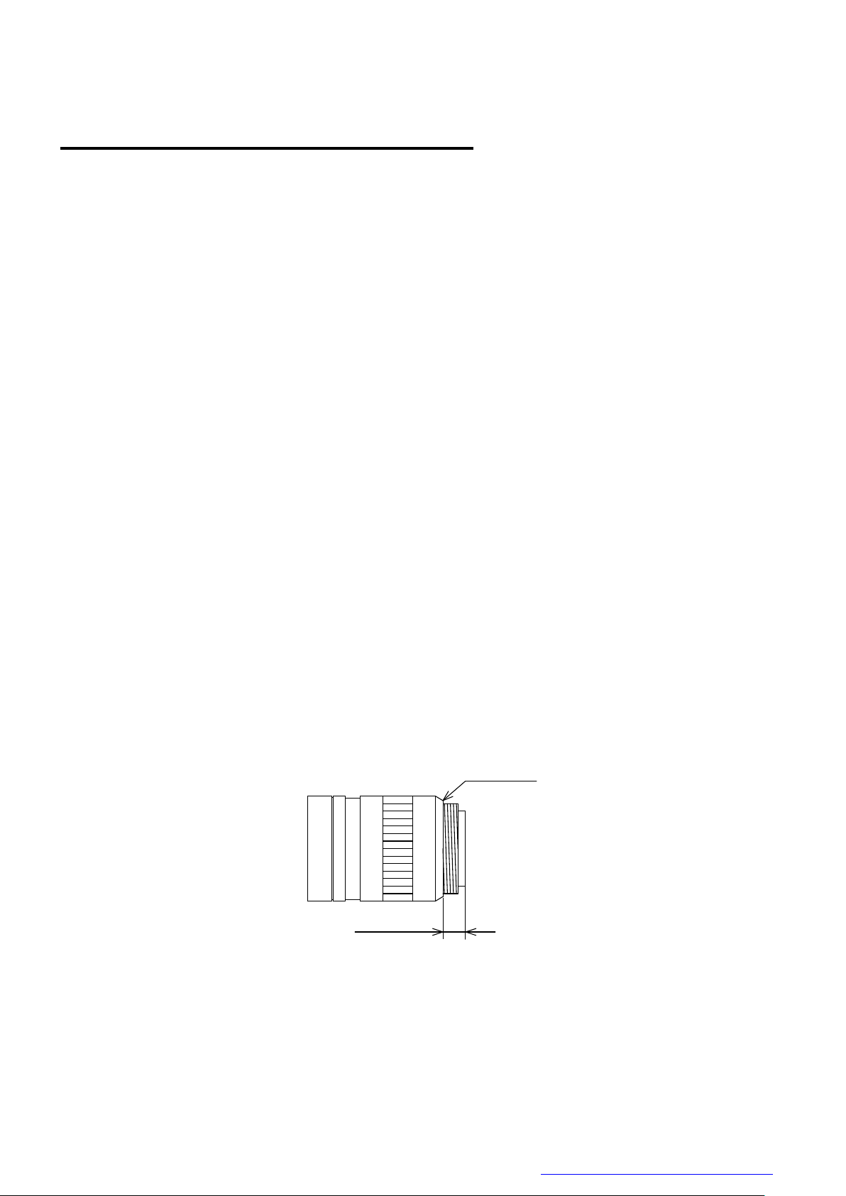
10mm or less
C-mount lens
Bottom of
the screw
Notes on using this product
● Handle carefully
Do not drop the equipment or allow it to be subject to strong impact or vibration, as such action may cause
malfunctions. Further, do not damage the connection cable, since this may cause wire breakage.
● Environmental operating conditions
Do not use the product in locations where the ambient temperature or humidity exceeds the specifications.
Otherwise, image quality may be degraded or internal components may be adversely affected. In particular,
do not use the product in areas exposed to direct sunlight. Moreover, during shooting under high
temperatures, vertical stripes or white spots (noise) may be produced, depending on the subject or camera
conditions (such as increased gain). However, such phenomena are not malfunctions.
● Check a combination with the lens
Depending on the lens and lighting you use, an image is reflected as a ghost in the imaging area. However,
this is not because of a fault of the camera.
In addition, depending on the lens you use, the performance of the camera may not be brought out fully due
to deterioration in resolution and brightness in the peripheral area, aberration and others.
Be sure to check a combination with the camera by using the lens and lightning you actually use.
When installing a lens in the camera, make sure carefully that it is not tilted.
In addition, use a mounting screw free from defects and dirt. Otherwise, the camera may be unable to be
removed.
Install a next lens; its dimension of protrusion from bottom of the screw is equal to or less than 10 mm. If a
lens does not stand to this condition, it might not be installed to this camera.
● Mounting to pedestal
When mounting this product to a pedestal, make sure carefully that lens doesn’t touch with the pedestal.
Copyright © 2016 TOSHIBA TELI CORPORATION, All rights reserved. http://www.toshiba-teli.co.jp/en/index.htm
7 / 81
Page 9

D4253386A
● Do not expose the camera's image-pickup-plane to sunlight or other intense light directly
Its inner CMOS sensor might be damaged.
● Occurrence of moiré
If you shoot thin stripe patterns, moiré patterns (interference fringes) may appear. This is not a malfunction.
● Occurrence of noise on the screen
If an intense magnetic or electromagnetic field is generated near the camera or connection cable, noise may
be generated on the screen. If this occurs, move the camera or the cable.
● Handling of the protective cap
If the camera is not in use, attach the lens cap to the camera to protect the image pickup surface.
● If the equipment is not to be used for a long duration
Turn off power to the camera for safety.
● Maintenance
Turn off power to the equipment and wipe it with a dry cloth.
If it becomes severely contaminated, gently wipe the affected areas with a soft cloth dampened with diluted
neutral detergent. Never use alcohol, benzene, thinner, or other chemicals because such chemicals may
damage or discolor the paint and indications.
If the image pickup surface becomes dusty, contaminated, or scratched, consult your sales representative.
8 / 81
Copyright © 2016 TOSHIBA TELI CORPORATION, All rights reserved. http://www.toshiba-teli.co.jp/en/index.htm
Page 10
D4253386A
Following information is only for EU-member states:
The use of the symbol indicates that this product may not be treated as household
waste. By ensuring this product is disposed of correctly, you will help prevent
potential negative consequences for the environment and human health, which could
otherwise be caused by inappropriate waste handling of this product. For more
detailed information about the take-back and recycling of this product, please contact
your supplier where you purchased the product.
“This symbol is applicable for EU member states only”
This equipment has been tested and found to comply with the limits for a class A digital device,
pursuant to Part 15 of the FCC Rules.
These limits are designed to provide reasonable protection against harmful interference when the
equipment is operated in a commercial environment.
This equipment generates, uses, and can radiate radio frequency energy and, if not installed and
used in accordance with the instruction manual, may cause harmful interference to radio
communication.
Operation of this equipment in a residential area is likely to cause harmful interference in which case
the user will be required to correct the interference at his own expense.
Defective pixels
A CMOS image sensor is composed of photo sensor pixels in a square grid array. Due to
the characteristics of CMOS image sensors, over- or under-driving of the pixels results in
temporary white or black areas (as if these are noises) appearing on the screen. This
phenomenon, which is not a defect is exacerbated under higher temperatures and long
exposure time.
Image shading
The brightness of the upper part of the screen may be different from that of the lower part. Note
that this is a characteristic of a CMOS image sensor and is not a fault.
● Disposal
When disposing of the camera, it may be necessary to disassemble it into separate parts, in accordance with
the laws and regulations of your country and/or municipality concerning environmental contamination.
[Phenomena specific to CMOS sensor]
Copyright © 2016 TOSHIBA TELI CORPORATION, All rights reserved. http://www.toshiba-teli.co.jp/en/index.htm
9 / 81
Page 11
D4253386A
环保使用期限标识,是根据电子信息产品污染控制管理办法以及,电子
信息产品污染控制标识要求(SJ/T11364-2006)、电子信息产品环保使用
期限通则,制定的适用于中国境内销售的电子信息产品的标识。
电子信息产品只要按照安全及使用说明内容,正常使用情况下,从生产
月期算起,在此期限内,产品中含有的有毒有害物质不致发生外泄或突
变,不致对环境造成严重污染或对其人身、财产造成严重损害。
产品正常使用后,要废弃在环保使用年限内或者刚到年限的产品时,请
根据国家标准采取适当的方法进行处置。
另外,此期限不同于质量/功能的保证期限。
The Mark and Information are applicable for People's Republic of
China only.
部件名称
有毒有害物质或元素
铅(Pb)
汞(Hg)
镉(Cd)
六价铬
(Cr(VI))
多溴联苯
(PBB)
多溴二苯醚
(PBDE)
相机本体
× ○ ○ ○ ○
○
○:表示该有毒有害物质在该部件所有均质材料中的含量均在电子信息产品中有毒有害物质的
限量要求标准规定的限量要求(SJ/T11363-2006)以下
×:表示该有毒有害物质至少在该部件的某一均质材料中的含量超出电子信息产品中有毒有害
物质的限量要求标准规定的限量要求(SJ/T11363-2006)
This information is applicable for People's Republic of China only.
中华人民共和国
环保使用期限
10
ペーパーボード
纸板
Paper board
箱/箱子/Box
内部緩衝材料・袋
内部缓冲材料·袋
Internal buffer materials・Bag
<产品中有毒有害物质或元素的名称及含量>
リサイクルに関する情報(包装物)
有关再利用的信息(包装物)
Information on recycling of wrapping composition
Copyright © 2016 TOSHIBA TELI CORPORATION, All rights reserved. http://www.toshiba-teli.co.jp/en/index.htm
10 / 81
Page 12

D4253386A
Installation
Before using this product, you shall install application software to display image and control registers of
camera, and IP configuration tool for network setting.
You can download the SDK for our USB camera products (TeliCamSDK) from the Service & Support section
of our website.
User registration is necessary to use downloading service. Please make a user registration, or contact your
sales representative.
● TOSHIBA TELI CORPORATION Top Page
http://www.toshiba-teli.co.jp/index.htm
● Service & Support
https://www.toshiba-teli.co.jp/cgi/ss/en/service.cgi
Please refer to the TeliCamSDK startup guide, about Operation environment, Installation, and Setup.
11 / 81
Copyright © 2016 TOSHIBA TELI CORPORATION, All rights reserved. http://www.toshiba-teli.co.jp/en/index.htm
Page 13

D4253386A
Specifications
Overview
This BU CMOS series is an integrated-(one-body)-type camera that adopts a global shutter CMOS sensor.
These are BU302MG (3M type1/1.8) BU505MG (5M type2/3). For video output and camera control, the USB
3.0 interface standard is adopted for high transfer rate, and it is easy to integrate into industrial equipment.
Features
● High frame rate
Supporting high frame rate, BU302MG 120fps, BU505MG 75fps.
● Global shutter
As it employs a global electronic shutter similar to a CCD image sensor, clear images of even fast-moving
object are obtainable with less blur.
● USB*3.0 interface
Video output and camera control are performed via the USB 3.0 standard interface. Data transfer is up to
5Gbps (Maximum) that enables to output uncompressed video data at high frame rate.
● USB3 Vision*
This product is based on USB3 Vision Ver.1.0.
● GenICam* Ver 2.3
This product is based on GenICam Generic Interface for Cameras Ver 2.3.
● IIDC2* Digital Camera Control Specification Ver.1.0.0
This product is based on IIDC2 Digital Camera Control Specification Ver.1.0.0.
12 / 81
Copyright © 2016 TOSHIBA TELI CORPORATION, All rights reserved. http://www.toshiba-teli.co.jp/en/index.htm
Page 14

D4253386A
● e-CON* Connector adoption
The e-CON connector adoption enables to assemble the cable easily without using special tools.
● Random Trigger Shutter
The Random Trigger Shutter function provides images in any timing by input of an external trigger signal.
Trigger control from PC is available as well.
● Scalable
Selectable video output area. This mode achieves higher frame rate by reducing vertical output area. And
reduces occupied data rate of USB bus by reducing horizontal output area.
● Binning
B/W models hove binning. In this mode, pixel data is combined by vertical and horizontal. Vertical binning
achieves high frame rate.
● Decimation
Camera reads all effective areas at high speed by skipping lines.
● Compact and lightweight
This camera is compact and lightweight; it is easy to integrate into industrial equipment.
● EU RoHS & Chinese ROHS
* USB is a unified standard established by USB-IF(USB Implementers Forum).
* USB3 Vision is a unified standard established by AIA (Automated Imaging Association).
* GeniCam is a registered trademark of EMVA (European Machine Vision Association).
* IIDC2 is a unified standard established by JIIA (Japan Industrial Association).
* e-CON (Easy & Economy connector) is a sensor connector that is normalized by the manufacturer of the
sensor, FA equipment and connector.
13 / 81
Copyright © 2016 TOSHIBA TELI CORPORATION, All rights reserved. http://www.toshiba-teli.co.jp/en/index.htm
Page 15

D4253386A
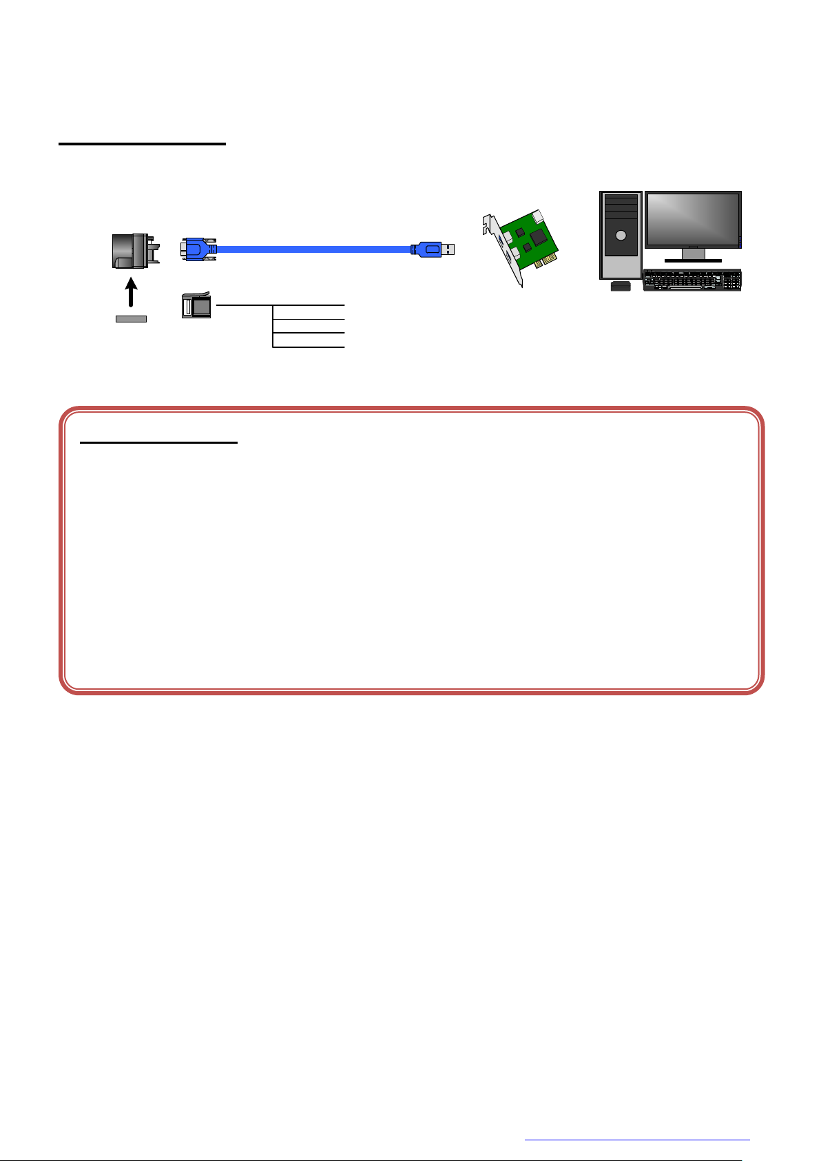
Configuration
The system configuration of this camera series is as follows;
This camera has no accessories, please prepare other equipments separately.
● Camera: This product. (BU)
● Camera mounting kit CPTBU (*1): To fix a camera to a tripod; attach this to the bottom of the camera.
● USB3.0 Cable (*2): This cable is used to connect the camera to host PC. Please use
a USB3.0 cable of Standard A - Micro B. This product is able to
connect a USB cable equipped with screw lock mechanism.
Please use it as needed.
● USB3.0 Interface Card (*2): This is the interface card to connect to the camera. Usually this
card is installed to expansion slot of PC etc.
● e-CON Cable. (*2): This cable is used to input external trigger signal and output GPIO
signal.
We recommend using shielded cable, because there is likely to be
affected by the noise depending on the operating environment of
the camera.
*1: Optional part. Contact your sales representative for details of option units.
*2: Commercial items.
14 / 81
Copyright © 2016 TOSHIBA TELI CORPORATION, All rights reserved. http://www.toshiba-teli.co.jp/en/index.htm
Page 16
D4253386A
Camera
Host(PC etc.)
Camera mounting unit
CPTBU
Interface Card
Stream Packet →← Control Packet
USB3.0 Cable
(Mirco B) (Standard A)
1. Line2
2. Line1
3. GND
4. Line0
(e-CON)
e-CON Cable
Notes on Connection:
- Please confirm the power supply of the camera off when plugging in or pulling out the I/O Connector. It causes the
breakdown.
- If your camera is used in a system where its connectors are subjected to strong repetitive shocks, its connectors are
possible to break down. If you use your camera in such a situation, use an USB3.0 cable with a lock screw, and secure
the camera cable as close as possible to the camera body for avoid physical shock to the camera connector.
- About e-CON cable: In the case that electric-wire is long or thin, input and output voltage may not satisfy specifications
of the camera or your system by voltage drop. Please confirm wires’ specifications before use them.
- Los t packets may occur by an electrical characteristic of the transmission line of USB3.0. (USB3.0 Interface Card,
USB3.0 Cable, and USB3.0 HUB).
Connection
Copyright © 2016 TOSHIBA TELI CORPORATION, All rights reserved. http://www.toshiba-teli.co.jp/en/index.htm
15 / 81
Page 17
D4253386A
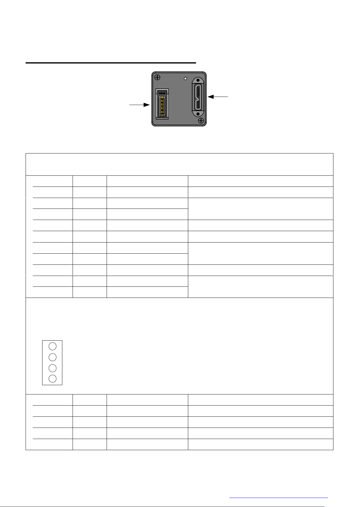
①
②
1. USB3.0 Interface Connector
Connector model: WMUR-10F6L1PH5N (WIN WIN PRECISION INDUSTRIAL)
Pin No.
I/O
Signal
Function
1 -
VBUS
Power
2 I/O
D-
USB2.0 differential pair
3 I/O
D+
4 -
NC
Not connected
5 -
GND
Ground for power return
6 O
SSTX-
SuperSpeed transmitter differential pair
7 O
SSTX+
8 -
GND_DRAIN
Ground for SuperSpeed signal return
9 I
SSRX-
SuperSpeed receiver differential pair
10 I SSRX+
2. I/O Connector
Connector (Camera side) 37204-62B3-004PL (Sumitomo 3M) or equivalent
Matching connector (Cable side) Connectors which conformed to e-CON
e.g. 37104 series (Sumitomo 3M), RITS 4P series (Tyco)
* Matching connector is not an accessory of this product.
Pin assignment
↑TOP
*Above figure is connector view from insert side.
Pin No.
I/O
Signal
Function
1 I/O
Line2
GPIO Input / Output
2 O
Line1
GPIO Output
3 -
GND
Ground
6 I
Line0
GPIO Input
1
2
3
4
Connector Pin Assignment
Rear View
Copyright © 2016 TOSHIBA TELI CORPORATION, All rights reserved. http://www.toshiba-teli.co.jp/en/index.htm
16 / 81
Page 18
D4253386A
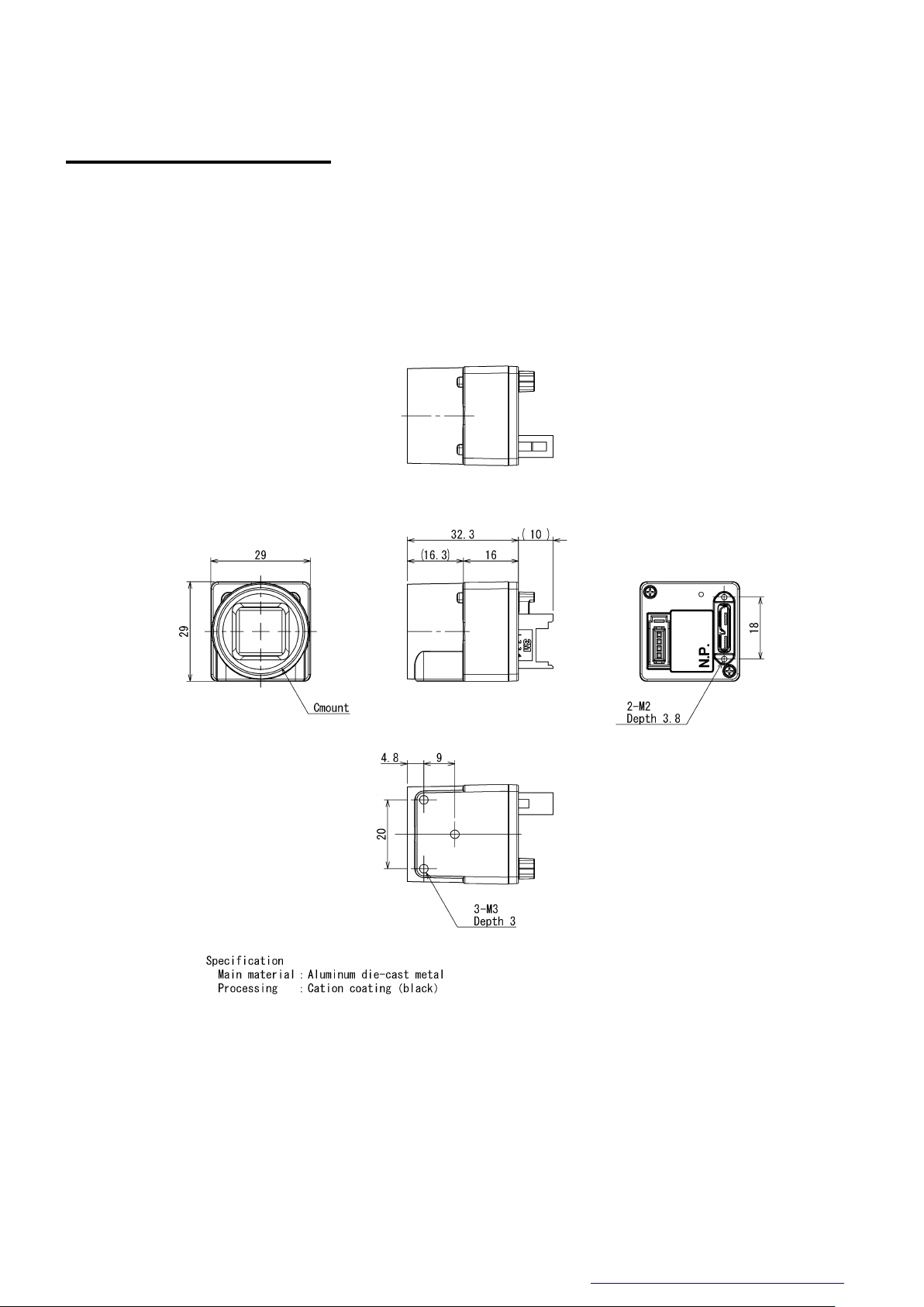
Outline Drawing
17 / 81
Copyright © 2016 TOSHIBA TELI CORPORATION, All rights reserved. http://www.toshiba-teli.co.jp/en/index.htm
Page 19

D4253386A
Model Name
BU302MG
BU505MG
Imager
CMOS image sensor
Number of effective pixels (H) × (V)
2064 x 1544
2464 x 2056
Optical Size
type1/1.8
type2/3
Scanning area (H) × (V)[mm]
7.12 × 5.33
8.50 × 7.09
Pixel size (H) × (V)[μm]
3.45 ×3.45
Scan method
Progressive
Electronic shutter method
Global shutter
Aspect ratio
4 : 3
6 : 5
Sensitivity
3250lx, F5.6, 1/120s
2100lx, F5.6, 1/75s
Minimum illuminance (*1)
7lx
5lx
Power supply
DC +5V5% (from USB connector)
Power consumption (*2)
3.2W (maximum)
Interface
USB 3.0 (Only SuperSpeed is supported)
Transmission speed
5Gbps (maximum)
Protocol
USB3 Vision
Image format
Mono8, Mono10, Mono12
Number of Video out pixels (H) × (V)
2048 × 1536
2448 × 2048
Maximum Frame rate (*2)
120fps
75fps
Dimensions
29 mm(W) x 29 mm (H) x 16 mm (D) (Not including protrusion)
Mass
Approximately 33g
Lens mount
C-mount
Flange back
17.526mm
Camera body grounding:
insulation status
Non-Conductive between circuit GND and camera body
General Specifications
B/W model
*1 F1.4, Gain: Maximum (+24dB), video level: 50%
*2 at the all pixel readout
Copyright © 2016 TOSHIBA TELI CORPORATION, All rights reserved. http://www.toshiba-teli.co.jp/en/index.htm
18 / 81
Page 20
D4253386A
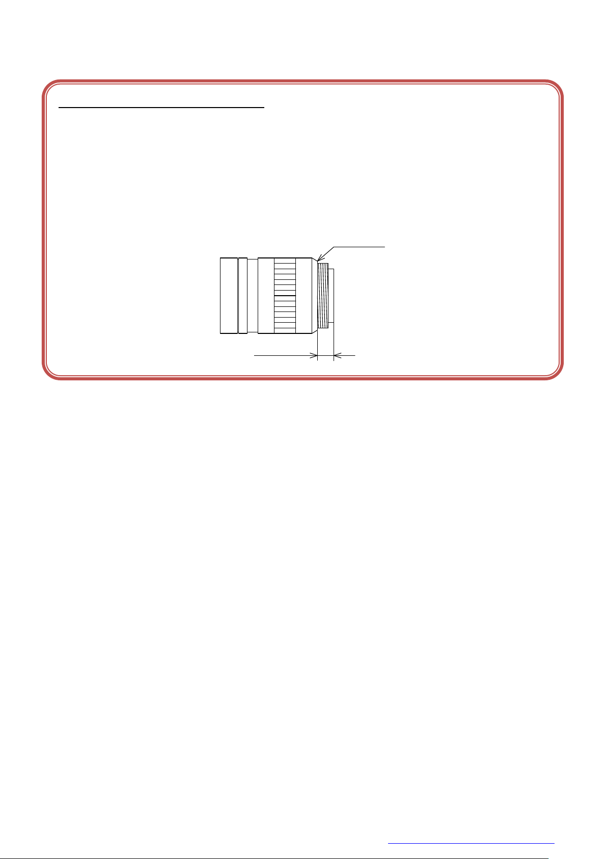
Notes on combination of C-mount lens:
- Depending on the lens you use, the performance of the camera may not be brought out fully due to the deterioration in
resolution and brightness in the peripheral area, occurrence of a ghost, aberration and others. When you check the
combination between the lens and camera, be sure to use the lens you actually use.
- In addition, use a mounting screw free from defects and dirt. Otherwise, the camera may be unable to be removed.
- As for the C-mount lens used combining this camera, the projection distance from bottom of the screw should use
10mm or less.
10mm or less
C-mount lens
Bottom of
the screw
19 / 81
Copyright © 2016 TOSHIBA TELI CORPORATION, All rights reserved. http://www.toshiba-teli.co.jp/en/index.htm
Page 21

D4253386A
Camera state
Lamp indication
No power
Off
Link detection in progress
Fast flash green (ON:20ms, OFF:60ms)
Connection Error
Flash alternate red / green
SuperSpeed connected, but no data being transferred
Flash green (ON: 200ms, OFF: 800ms)
SuperSpeed connected, waiting for trigger
Flash orange (ON: 200ms, OFF: 800ms)
Data being transferred
Fast flash green (ON:60ms, OFF:20ms)
Error during data transfer
Solid Red (Time period: 500ms)
Stand-by
Super slow flash orange (ON:200ms, OFF: 2800ms)
LED status
Copyright © 2016 TOSHIBA TELI CORPORATION, All rights reserved. http://www.toshiba-teli.co.jp/en/index.htm
20 / 81
Page 22
D4253386A
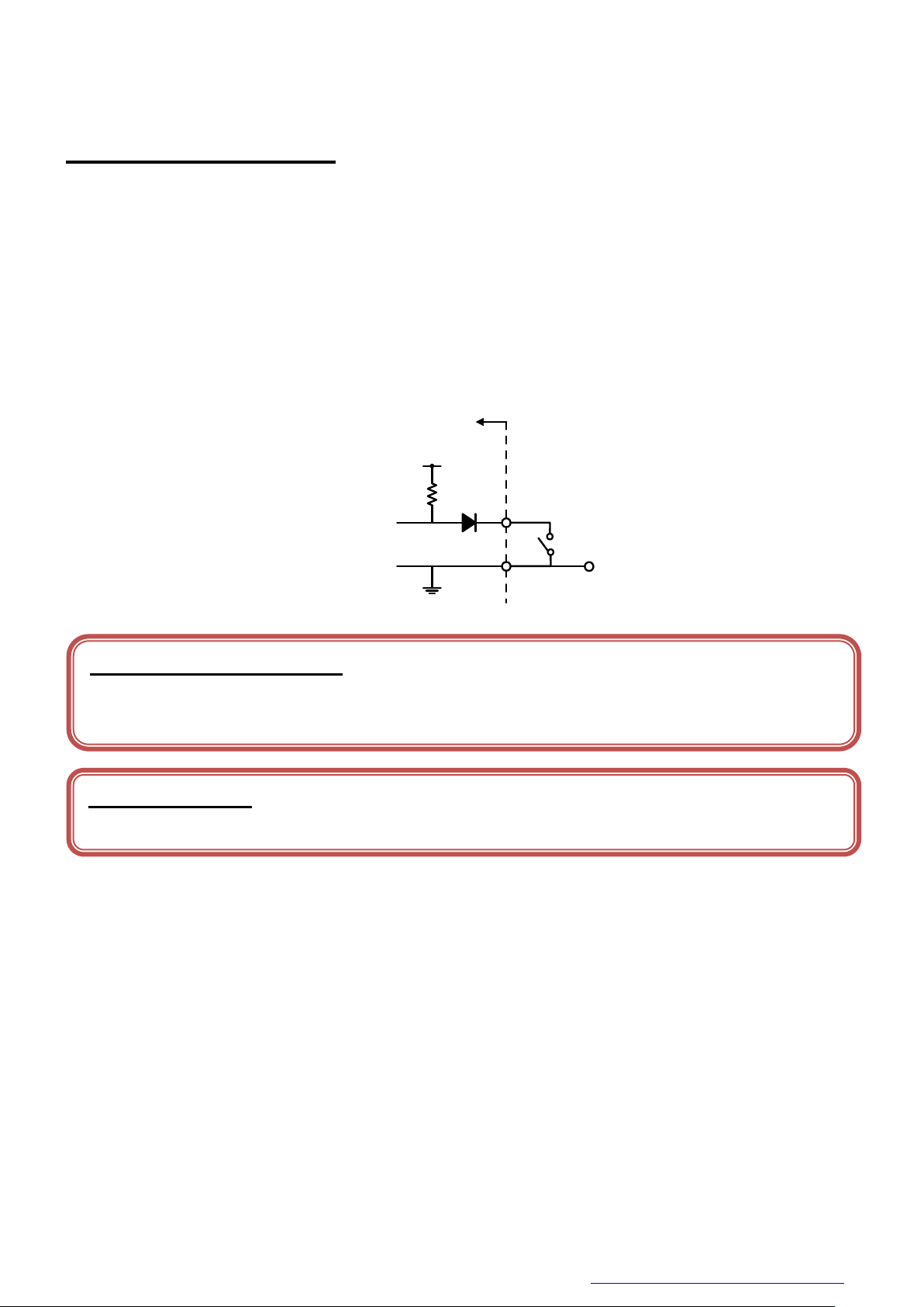
Inside
DC3.3V
0V
10kΩ
Notes of external trigger signal:
Depending on cable length, cable kinds and input current of trigger input line, Random Trigger Shutter operation may not
satisfy timing specification or camera may not receive EXT_TRIG signal. Please confirm it before use.
Notes of input level:
Line0 and Line2 have different input level. Please use input level within the voltage described in this specification.
I/O Specification
● Signal Specification
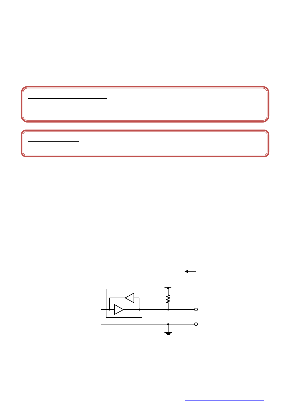
- Line0 (GPIO Input, I/O connector : 4 pin)
Input Circuit : LVTTL
Level : Low 0 ~ 0.5V, High 2.0 ~ 24.0V
Polarity : High active / Low active (initial factory setting: Low active)
Pulse Width : Minimum 50μs
Input circuit diagram
Copyright © 2016 TOSHIBA TELI CORPORATION, All rights reserved. http://www.toshiba-teli.co.jp/en/index.htm
21 / 81
Page 23
D4253386A
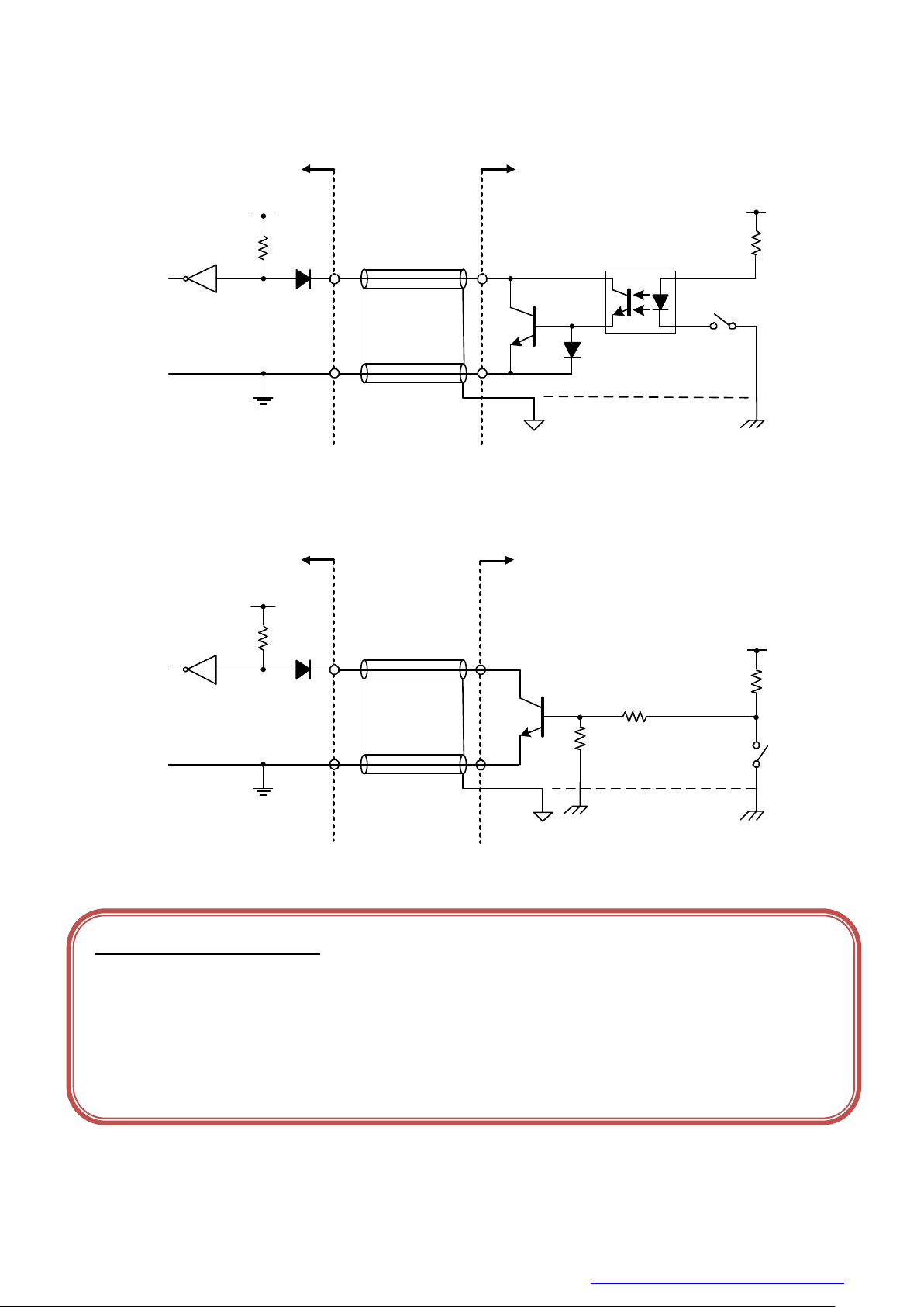
● External trigger input recommended circuit
CAMERA Inside
DC3.3V
10kΩ
4
3
Photocoupler
Camera
GND
Your
GND
Your system
Your
Secondary GND
Your
GND
Your system
Your
FRAME GND
DC3.3V
10kΩ
4
3
Camera
GND
CAMERA Inside
Notes of trigger input cable:
- The recognition of the trigger signal depends on the length, characteristic or driving current of the cable. Therefore
please confirm your system about those conditions.
- Pin 3 is signal ground. It isn’t conducted with camera frame.
Using shield cable, terminal processing of the shield is referred as above.
- Please confirm the EMC adaptability in whole of your system.
- Isolated I/F
- Non-Isolated I/F
Copyright © 2016 TOSHIBA TELI CORPORATION, All rights reserved. http://www.toshiba-teli.co.jp/en/index.htm
22 / 81
Page 24
D4253386A
- Line2 (GPIO Input / Output, initial factory setting: Input, I/O connector : 1 pin)
Inside
DC5.0V
10kΩ
1
3
IOLineModeAll
Notes of external trigger signal:
Depending on cable length, cable kinds and input current of trigger input line, Random Trigger Shutter operation may not
satisfy timing specification or camera may not receive EXT_TRIG signal. Please confirm it before use.
Notes of input level:
Line0 and Line2 have different input level. Please use input level within the voltage described in this specification.
- Input signal specification
Level : Low 0 ~ 0.5V, High 4.0 ~ 5.0V
Polarity : High active / Low active (initial factory setting: Low active)
Pulse Width : Minimum 50μs
- Output signal specification
Output Circuit : 5V CMOS
Maximum Current : +/-32mA
Polarity : High active / Low active (initial factory setting: Low active)
Signal Source : TIMER0 ACTIVE
USER OUTPUT
EXPOSURE ACTIVE
FRAME ACTIVE
FRAME TRANSFER
FRAME TRIGGER WAIT
Input / Output circuit diagram
Copyright © 2016 TOSHIBA TELI CORPORATION, All rights reserved. http://www.toshiba-teli.co.jp/en/index.htm
23 / 81
Page 25

D4253386A
- Line1 (GPIO Output, I/O connector : 2 pin)
Output Circuit : 5V CMOS
Maximum Current : +/-32mA
Polarity : High active / Low active (initial factory setting: Low active)
Signal Source : TIMER0 ACTIVE
USER OUTPUT
EXPOSURE ACTIVE
FRAME ACTIVE
FRAME TRANSFER
FRAME TRIGGER WAIT
24 / 81
Copyright © 2016 TOSHIBA TELI CORPORATION, All rights reserved. http://www.toshiba-teli.co.jp/en/index.htm
Page 26

D4253386A
T2
T1
USB bus
Exposure
Image Image
Model Name
format
T1
[ms]
T2
[s]
Default Framerate
[fps]
BU302MG
Mono8
8.1
1/(Frame Rate setting)
120
Mono10, Mono12
9.6
60
BU505MG
Mono8
12.9
75
Mono10, Mono12
15.3
37
Timing Specification
Image data outputs are transferred with USB bulk transfer. Timing numerical value below is described by
absolute prerequisite that camera can use transmission band without restriction of other device. When there
is other device on the same bus, the value described below is not guaranteed.
● In normal shutter mode
Copyright © 2016 TOSHIBA TELI CORPORATION, All rights reserved. http://www.toshiba-teli.co.jp/en/index.htm
25 / 81
Page 27

D4253386A
Image
USB bus
Exposure
TRIG_IN
T3
T1
Image
USB bus
Exposure
TRIG_IN
T3
T1
T4
Model Name
T3 [μs]
T4 [μs]
BU302MG
15.8
29.5
BU505MG
18.8
32.6
Notes of random trigger shutter mode:
- In the period when FRAME_TRIGGER_WAIT (GPIO signal) is inactive, user must not input external trigger signal to
this camera.
- When the interval of the input trigger signal is extremely short, or when the trigger signal is noisy, there is a possibility
of causing the malfunction. In this case, please input a proper trigger signal.
● In Random Trigger Shutter mode
Edge mode / Bulk mode (at all pixels readout)
Level mode (at all pixels readout)
* The value of T1 is the same as the value of normal shutter mode.
* T3 and T4 are typical value.
Copyright © 2016 TOSHIBA TELI CORPORATION, All rights reserved. http://www.toshiba-teli.co.jp/en/index.htm
26 / 81
Page 28

D4253386A
Typical Spectral Response
* The lens characteristics and light source characteristics is not reflected in table.
● BU302MG / BU505MG
27 / 81
Copyright © 2016 TOSHIBA TELI CORPORATION, All rights reserved. http://www.toshiba-teli.co.jp/en/index.htm
Page 29

D4253386A
Notes on Heat Radiation:
The temperature of camera housing must be kept less than 50 °C.
Please provide sufficient heat radiation depending on your installation.
Operating Ambient Conditions
● Ambient conditions
- Operating Assurance
Temperature: 0°C to +40°C, Camera housing temperature: less than 50°C
Humidity: 10% to 90% (no condensation)
- Storage Assurance
Temperature: -20°C to +60°C
Humidity: 90% or less (no condensation)
● EMC Conditions
- EMI (Electro-Magnetic Interference): EN61000-6-4
FCC Part 15 Subpart B Class A
- EMS (Electro-Magnetic Susceptibility): EN61000-6-2
Copyright © 2016 TOSHIBA TELI CORPORATION, All rights reserved. http://www.toshiba-teli.co.jp/en/index.htm
28 / 81
Page 30

D4253386A
Notes on Conformity of the EMC:
The adaptability of the safety standard of this camera is assured in the condition of combination with the following parts:
- USB Cable USB3-KR1-A-MBS-030 (OKI Electric Cable Co., Ltd.)
- e-CON Cable 3.0m, Shield cable (Fabricated parts)
Parts:
- e-CON connector XN2A-1470 (OMRON Corporation)
- Shielded wire UL1533 (AWG28) (Hitachi cable, Ltd.)
Connection:
e-CON
1
2
3
4
BNC
GPIO(Line2)
GPIO(Line1)
GND
TRIG IN(Line0)
GPIO(Line2)
GPIO(Line1)
TRIG IN(Line0)
BNC
Please confirm the EMC adaptability when it combines with parts other than them.
29 / 81
Copyright © 2016 TOSHIBA TELI CORPORATION, All rights reserved. http://www.toshiba-teli.co.jp/en/index.htm
Page 31

D4253386A
Category
Function
USB3 Vision
Bootstrap Registers
USB3 Vision standard registers
DeviceControl
DeviceControl
Device information
ImageFormatControl
ImageFormatSelector
Image format selection
Scalable
Scalable control
Binning
Binning control
Decimation
Decimation control
Reverse
Image flip
PixelFormat
Pixel format selection
TestPattern
Test pattern control
AcquisitionControl
AcquisitionControl
Image stream start / stop
ImageBuffer
Image buffer control
TriggerControl
Trigger control
ExposureControl
Exposure time control
DigitalIOControl
DigitalIOControl
GPIO signal control
CounterAndTimerControl
TimerControl
Timer0Active signal control
AnalogControl
Gain
Gain control
BlackLevel
Black level control
Gamma
Gamma correction
LUTControl
LUTControl
LUT control
UserSetControl
UserSetControl
Load / Save user setting
EventControl
EventControl
Event packet control
VenderUniqueControl
FrameSynchronization
Frame synchronization control
LEDIndicatorLuminance
LED luminance control
AntiGlitch
AntiGlitch control
AntiChattering
AntiChattering control
DPCControl
DPCControl
Defect pixel correction control
SequentialShutterControl
SequentialShutterControl
Sequential shutter control
Functions
This section introduces standard functions. BU CMOS series provides following functions.
Copyright © 2016 TOSHIBA TELI CORPORATION, All rights reserved. http://www.toshiba-teli.co.jp/en/index.htm
30 / 81
Page 32

D4253386A
Function
BU302MG
BU505MG
Bootstrap Registers
○
○
DeviceControl
○
○
ImageFormatSelector
○
○
Scalable
○
○
Binning
○
○
Decimation
○
○
Reverse
○
○
PixelFormat
○
○
TestPattern
○
○
AcquisitionControl
○
○
ImageBuffer
○
○
TriggerControl
○
○
ExposureControl
○
○
DigitalIOControl
○
○
TimerControl
○
○
Gain
○
○
BlackLevel
○
○
Gamma
○
○
LUTControl
○
○
UserSetControl
○
○
EventControl
○
○
FrameSynchronization
○
○
LEDIndicatorLuminance
○
○
AntiGlitch
○
○
AntiChattering
○
○
DPCControl
○
○
SequentialShutterControl
○
○
Features supported by each model are as follows.
Details of each feature are described in following pages.
Copyright © 2016 TOSHIBA TELI CORPORATION, All rights reserved. http://www.toshiba-teli.co.jp/en/index.htm
31 / 81
Page 33

D4253386A
USB3 Vision ABRM
Register
Visibility
Access
Description
UserDefinedName
Expert
R/W
Store user’s arbitrary string in non-volatile memory.
USB3 Vision SIRM
Register
Visibility
Access
Description
StreamEnable
-
R/W
Open and close the stream channel.
USB3 Vision EIRM
Register
Visibility
Access
Description
EventEnable
Expert
R/W
Activate event notification function.
Please refer to EventControl section as well.
TriggerEventTest
Expert
W
Issue test event packet.
Bootstrap Registers
This camera is based on USB3 Vision.
Please refer to USB3 Vision specification for details about Bootstrap Registers defined in USB3 Vision.
AIA (Automated Imaging Association) USB3 Vision Homepage.
http://www.visiononline.org/vision-standards-details.cfm?type=11
Followings are commonly used registers.
● Registers
● Note
When opening and closing the stream channel, it is required to control StreamEnable plus SDK setups on
your application. Please refer to the TeliCamSDK for details.
Copyright © 2016 TOSHIBA TELI CORPORATION, All rights reserved. http://www.toshiba-teli.co.jp/en/index.htm
32 / 81
Page 34

D4253386A
Register
Visibility
Access
Description
DeviceReset
Expert
W
Resets the device.
DeviceVendorName
Beginner
R
Returns the vendor name.
DeviceModelName
Beginner
R
Returns the model name.
DeviceManufacturerInfo
Beginner
R
Returns the manufacturer information.
DeviceVersion
Beginner
R
Returns the device version.
DeviceID
Beginner
R
Returns the device ID (serial number).
DeviceControl
Registers of this category provide various information of the camera. And you can set the free user ID to the
camera.
● Registers
Copyright © 2016 TOSHIBA TELI CORPORATION, All rights reserved. http://www.toshiba-teli.co.jp/en/index.htm
33 / 81
Page 35

D4253386A
Register
Visibility
Access
Description
ImageFormatSelector
Beginner
R/W
Selects an image format.
ImageFormatSelector
Function
Format0 (*)
Scalable
Format1
Binning
Format2
Decimation
ImageFormatControl
Registers of this category are related to image format control.
● Registers
● Setting
- Select an image format.
Set a following value to “ImageFormatSelector” register. Setting value is Enumeration type.
* initial factory setting
● Note
Changing “ImageFormatSelector” register value is invalid during image stream data output.
Copyright © 2016 TOSHIBA TELI CORPORATION, All rights reserved. http://www.toshiba-teli.co.jp/en/index.htm
34 / 81
Page 36

D4253386A
⇒
( X , Y )=( 4 * i , 2 * j )
A + 4 * m
B + 2 * n
Register
Visibility
Access
Description
Width
Beginner
R/W
Sets width (in pixels) of the image data.
Height
Beginner
R/W
Sets Height (in pixels) of the image data.
OffsetX
Beginner
R/W
Sets horizontal offset (in pixels) from the origin to the region of interest.
OffsetY
Beginner
R/W
Sets vertical offset (in pixels) from the origin to the region of interest.
Scalable
BU series provides the scalable that can read out defined area of the screen.
In the scalable mode, camera reads out only necessary area at the normal speed and reads out other area
at high speed. The frame rate can be faster when the vertical height size is small. However, the frame rate
cannot be faster only when the horizontal width size is small.
Only single rectangle is selectable. Concave or convex shape is not selectable.
- Window size: {A + 4 × m (H)} × {B + 2 × n (V)}
A, B = minimum unit size
m, n = integer
The window size is equal or less than maximum image size.
- Start address: {4 x i (H)} x {2 x j (V)}
i, j = integer
The window size is equal or less than maximum image size.
● Registers
Scalable
Copyright © 2016 TOSHIBA TELI CORPORATION, All rights reserved. http://www.toshiba-teli.co.jp/en/index.htm
35 / 81
Page 37

D4253386A
Model
BU302MG
BU505MG
Width/OffsetX unit size
4
4
Height/OffsetY unit size
2 2 Minimum unit size
64 x 64
64 x 64
Maximum unit size (*)
2048 x 1536
2448 x 2048
● Setting
- Select an image format.
Select “Fomat0” of “ImageFormatSelector” register.
- Set image size and image start position
Set the following value to “Width”, “Height”, “OffsetX”, “OffsetY” registers. Setting value is Integer type.
“Width”, “Height” registers are image size setting. “OffsetX”, “OffsetY” registers are image start position
setting.
* initial factory setting
● Note
Changing “Width”, “Height”, “OffsetX”, “OffsetY” register value is invalid during image stream data output.
Copyright © 2016 TOSHIBA TELI CORPORATION, All rights reserved. http://www.toshiba-teli.co.jp/en/index.htm
36 / 81
Page 38

D4253386A
2048
2448
1224
All pixel readout
Binning
1024
Register
Visibility
Access
Description
BinningHorizontal
Beginner
R/W
Set horizontal binning.
BinningVertical
Beginner
R/W
Set vertical binning.
Binning
B/W models have 2 x 2 binning. In the binning mode, a pixel is added with the neighboring pixel(s). This
increases the sensitivity of the image. It’s alike scalable, the frame rate can be faster and USB bandwidth
occupation decrease.
● Registers
Binning operation (e.g. BU505MG)
Copyright © 2016 TOSHIBA TELI CORPORATION, All rights reserved. http://www.toshiba-teli.co.jp/en/index.htm
37 / 81
Page 39

D4253386A
● Setting
- Select an image format.
Select “Fomat1” of “ImageFormatSelector” register.
- Set binning operation
Set the “2” to “BinningHorizontal”, “BinningVertical” registers. When you set up a value of the one side for
horizontal or vertical binning, the other side of the value is set up automatically. Setting value is Integer
type.
● Note
Binning is disabled when the camera is running in Scalable mode or Decimation mode.
Scalable and Decimation are disabled when the camera is running in Binning mode.
Changing “BinningHorizontal”, “BinningVertical” register value is invalid during image stream data output.
38 / 81
Copyright © 2016 TOSHIBA TELI CORPORATION, All rights reserved. http://www.toshiba-teli.co.jp/en/index.htm
Page 40

D4253386A
2048
2448
All pixel readout
Decimation
1024
1224
Register
Visibility
Access
Description
DecimationHorizontal
Biginner
R/W
Set the number of horizontal Decimation line(s).
DecimationVertical
Beginner
R/W
Set the number of vertical Decimation line(s).
Decimation
Cameras have 2 x 2 decimation, cameras read all effective areas at high speed by skipping lines.
● Registers
Decimation operation (e.g. BU505MG)
Copyright © 2016 TOSHIBA TELI CORPORATION, All rights reserved. http://www.toshiba-teli.co.jp/en/index.htm
39 / 81
Page 41

D4253386A
● Setting
- Select an image format.
Select “Fomat2” of “ImageFormatSelector” register.
- Set Decimation lines
Set the “2” to “DecimationHorizontal”, “DecimationVertical” registers. When you set up a value of the one
side for horizontal or vertical binning, the other side of the value is set up automatically. Setting value is
Integer type.
● Note
Decimation is disabled when the camera is running in Scalable mode or Binning mode.
Scalable and Binning are disabled when the camera is running in Decimation mode.
Changing “DecimationHorizontal”, “DecimationVertical” register value is invalid during image stream data
output.
40 / 81
Copyright © 2016 TOSHIBA TELI CORPORATION, All rights reserved. http://www.toshiba-teli.co.jp/en/index.htm
Page 42

D4253386A
ReverseX
ReverseY ReverseX+ReverseY
Register
Visibility
Access
Description
ReverseX
Expert
R/W
Flip image in horizontal direction.
ReverseY
Expert
R/W
Flip image in vertical direction.
Value
Image reverse
FALSE (*)
Non reverse
TRUE
Reverse
Reverse
Image can be flipped in horizontal and/or vertical direction.
● Registers
● Setting
- Set image reverse
Set the following value to “ReverseX”, “ReverseY” registers. Setting value is Boolean type.
* initial factory setting
● Note
Copyright © 2016 TOSHIBA TELI CORPORATION, All rights reserved. http://www.toshiba-teli.co.jp/en/index.htm
41 / 81
Page 43

D4253386A
Register
Visibility
Access
Description
PixelCoding
Beginner
R/W
Selects a pixel coding.
PixelSize
Beginner
R/W
Selects a bit size of image pixel.
PixelEndian
Beginner
R/W
Selects a pixel endian.
PixelFormat
Beginner
R
Returns a selected pixel format.
PixelFormat is conformed to AIA Pixel Format Naming Convention.
PixelSize
PixelCoding
Bpp8
Bpp10
Bpp12
Mono
PixelFormat ID
Mono8 (*)
Mono10
Mono12
0x01080001
0x01100003
0x01100005
PixelFormat
Select a pixel format of image stream data.
● Registers
● Setting
- Set PixelFormat
PixelFormat is determined by combination of “PixelCoding” and “PixelSize” register. Select a following
combination to “PixelCoding” and “PixelSize” register. Setting values are Enumeration type.
B/W model
* initial factory setting
● Note
Changing “PixelSize” register value is invalid during image stream data output.
Copyright © 2016 TOSHIBA TELI CORPORATION, All rights reserved. http://www.toshiba-teli.co.jp/en/index.htm
42 / 81
Page 44

D4253386A
TestPattern
BU series supports test pattern data output. Camera provides following Test patterns;
Black White
GreyA GreyB
GreyHorizontalRamp GreyVerticalRamp
GreyScale
Test pattern (e.g. BU505MG)
43 / 81
Copyright © 2016 TOSHIBA TELI CORPORATION, All rights reserved. http://www.toshiba-teli.co.jp/en/index.htm
Page 45

D4253386A
Register
Visibility
Access
Description
TestPattern
Beginner
R/W
Selects a test pattern.
TestPattern
function
Off (*)
Test pattern disable(Normal data output)
Black
All pixel = 0 LSB
White
All pixel = 255 @Mono8
GreyA
All pixel = 170 @Mono8
GreyB
All pixel = 85 @Mono8
GreyHorizontalRamp
Horizontal Ramp
GreyVerticalRamp
Vertical Ramp
GreyScale
Grey scale
● Registers
● Setting
- Select a test pattern output
Set the following value to “TestPattern” register. Setting value is Enumeration type.
The camera generates a test pattern.
● Note
* initial factory setting
Copyright © 2016 TOSHIBA TELI CORPORATION, All rights reserved. http://www.toshiba-teli.co.jp/en/index.htm
44 / 81
Page 46

D4253386A
Register
Visibility
Access
Description
AcquisitionMode
Beginner
R/W
Selects an acquisition mode.
AcquisitionStart
Beginner
W
Executes the image stream output start.
AcquisitionStop
Beginner
W
Executes the image stream output stop.
AcquisitionAbort
Beginner
W
Executes the image stream output abort.
AcquisitionFrameCount
Beginner
R/W
Sets the number of frames to transfer in MultiFrame mode.
AcquisitionFrameRateControl
Beginner
R/W
Activates frame rate setting.
AcquisitionFrameRate
Beginner
R/W
Sets frame rate of image stream.
AcquisitionFrameIntervalControl
Beginner
R/W
Activates frame interval setting.
AcquisitionFrameInterval
Beginner
R/W
Sets frame interval of image stream.
AcquisitionMode
Function
Continuous (*)
Continuous image transfer
MultiFrame
Multi frame image transfer
AcquisitionControl
Make a setting of image stream and control image stream output.
Camera starts image stream output by receiving AcquisitionStrat command. And there are some registers
that require camera to stop image stream output to change values.
Acquisition frame rate is variable. Maximum acquisition frame rate depends on camera operation mode
(scalable.)
● Registers
● Setting
- Select an acquisition mode
Set the following value to “AcquisitionMode” register. Setting value is Enumeration type.
* initial factory setting
- Set the number of frames to transfer (In MultiFrame mode)
Set the number of frames to transfer to “AcquisitionFrameCount”. Setting value is Integer type.
Copyright © 2016 TOSHIBA TELI CORPORATION, All rights reserved. http://www.toshiba-teli.co.jp/en/index.htm
45 / 81
Page 47

D4253386A
AcquisitionFrameRateControl
Function
NoSpecify (*)
The frame rate is determined by giving priority to ExposureTime setting value.
Manual
The frame rate is determined by giving priority to AcquisitionFrameRate setting value.
AcquisitionFrameRate
Value
Minimum
0.5[Hz]
Maximum (*)
Depend on register setting of "Height".
Notes on Frame Drops of Image:
Depends on your PC or USB3.0 interface card configurations, images may not be captured normally (e.g. frame drops
may occur). In this case, change to frame rate setting lower.
- Open/Close stream channel (to be ready to receive stream data)
Set “1” to “StreamEnable” in Bootstrap Registers before “AcquisitionStart”.
Set “0” to “StreamEnable” in Bootstrap Registers before “AcquisitionStop” or “AcquisitionAbort”.
- Start image stream output
The camera starts image stream output by executing “AcquisitionStart” register command.
- Stop image stream output
The camera stops image stream output by executing “AcquisitionStop” register command.
The camera aborts image stream output by executing “AcquisitionAbort” register command.
- Set frame rate
Set the “AcquisitionFrameRateControl” register to “Manual”.
And set the following value to “AcquisitionFrameRate” register. Setting value is Float type.
The range of register setting depends on camera model, and camera operation mode.
“AcquisitionFrameInterval” register is a reciprocal of “AcquisitionFrameRate”.
* initial factory setting
* initial factory setting
● Note
Changing “AcquisitionFrameRateControl”, “AcquisitionFrameRate”, “AcquisitionFrameIntervalControl”,
“AcquisitionFrameInterval” register value is invalid during image stream data output.
When exposure time setting is longer than frame rate setting, camera operation gives priority to exposure
time setting.
When opening and closing the stream channel, it is required to control StreamEnable plus SDK setups on
your application. Please refer to the TeliCamSDK for details.
46 / 81
Copyright © 2016 TOSHIBA TELI CORPORATION, All rights reserved. http://www.toshiba-teli.co.jp/en/index.htm
Page 48

D4253386A
Register
Visibility
Access
Description
ImageBufferMode
Beginner
R/W
Selects Image Buffer mode.
ImageBufferFrameCount
Beginner
R
Returns the number of frames stored in the buffer.
ImageBufferRead
Beginner
W
Executes the image buffer read.
ImageBuffer
This section describes ImageBuffer control of AcquisitionControl category.
Camera stores images temporarily in image buffer, and read them out in arbitrary timing.
This function is typically used in Random Trigger Shutter mode.
Please refer to TriggerControl section as well.
● Registers
● Setting
- Activate trigger mode
Set “On” to “TriggerMode” register, and set “TriggerSoftware” or “Line0”, “Line2” to ”TriggerSource”
register.
- Activate image buffer mode
Set “On” to “ImageBufferMode” register.
- Open/Close stream channel (to be ready to receive stream data)
Set “1” to “StreamEnable” in Bootstrap Registers before “ImageBufferRead”.
Set “0” to “StreamEnable” in Bootstrap Registers after completion of image acquisition from image buffer.
- Capture and store images
Input trigger signals to capture and store images.
“ImageBufferFrameCount” register shows the number of frames stored in the buffer.
The maximum number of frames storable depends on the image size. (maximum 64MByte.)
- Set the number of frames to transfer (In ImageBuffer mode)
Set the number of frames to transfer to “AcquisitionFrameCount”. Setting value is Integer type.
- Read images from the buffer
Read the number of AcquisitionFrameCount image(s) from the buffer by executing “ImageBufferRead”
register command (it is equivalent to write value 10 to “AcquisitionCommand” register).
Copyright © 2016 TOSHIBA TELI CORPORATION, All rights reserved. http://www.toshiba-teli.co.jp/en/index.htm
47 / 81
Page 49

D4253386A
● Note
When opening and closing the stream channel, it is required to control StreamEnable plus SDK setups on
your application. Please refer to the TeliCamSDK for details.
[Start] button in TeliCamViewer can’t deal with “StreamEnable” register alone.
Please substitute procedure “StreamEnable” = 1 to following instructions.
- Push [Start] button on TeliCamViewer main window.
- Execute [AcquisitionStop] in XML window.
48 / 81
Copyright © 2016 TOSHIBA TELI CORPORATION, All rights reserved. http://www.toshiba-teli.co.jp/en/index.htm
Page 50

D4253386A
Trigger Mode
Synchronization
Exposure Control
Normal Shutter mode
Free run
“ExposureTime” register control
Random Trigger Shutter mode
HardwareTrigger
-Edge mode:TriggerSequence0
-Bulk mode:TriggerSequence6
“ExposureTime” register control
-Level mode:TriggerSequence1
Trigger pulse width control
SoftwareTrigger
-Edge mode:TriggerSequence0
-Bulk mode:TriggerSequence6
“ExposureTime” register control
TriggerControl
This section describes trigger control of TriggerControl category for the BU series.
This camera series provides two kinds of exposure synchronization.
1. Normal Shutter mode : Free run operation (internal synchronization)
2. Random Trigger Shutter mode : Synchronized with external trigger input
In Random Trigger Shutter mode, two kinds of trigger input are available.
1. Trigger signal via the I/O connector (HardwareTrigger)
2. Trigger command via the USB interface (SoftwareTrigger)
The following table shows the combination of operation mode of this camera series.
Table. Operation Mode
Copyright © 2016 TOSHIBA TELI CORPORATION, All rights reserved. http://www.toshiba-teli.co.jp/en/index.htm
* The camera operation not mentioned above is not guaranteed.
49 / 81
Page 51

D4253386A
Image
USB bus
Exposure
Trigger
ExposureTime
USB bus
Exposure
Trigger
Pulse Width
Image
Image
USB bus
Exposure
Trigger
ExposureTime
Image Image
TriggerAdditionalParameter = 3
USB bus
Exposure
Trigger signal
Image
TriggerDelay
- Edge mode (TriggerSequence0)
The exposure time is determined by Exposure Time setting.
- Level mode (TriggerSequence1)
The exposure time is determined by the pulse width of the trigger signal.
- Bulk mode (TriggerSequence6)
Camera exposes and transfers multiple frames by a single trigger.
Trigger sequence
Operation point of HardwareTrigger is at the edge of trigger signal, and active edge polarity is able to change
by register setting. And you can add delay time from trigger edge to exposure start by register setting.
Details of Random Trigger Shutter operation, refer to "Timing" of "Specification".
Copyright © 2016 TOSHIBA TELI CORPORATION, All rights reserved. http://www.toshiba-teli.co.jp/en/index.htm
Trigger Delay
50 / 81
Page 52

D4253386A
Register
Visibility
Access
Description
TriggerMode
Beginner
R/W
Selects Random Trigger Shutter mode.
TriggerSequence
Beginner
R/W
Selects trigger sequence.
TriggerSource
Beginner
R/W
Selects trigger source of Random Trigger Shutter.
TriggerAdditionalParameter
Expert
R/W
Sers the number of frames to exposure in Bulk mode.
TriggerDelay
Beginner
R/W
Sets trigger delay.
TriggerSoftware
Beginner
W
Executes software trigger.
TriggerMode
Function
Off (*)
Normal Shutter Mode
On
Random Trigger Shutter mode
TriggerSequence
Function
TriggerSequence0 (*)
Edge mode
TriggerSequence1
Level mode
TriggerSequence6
Bulk mode
TriggerSource
Function
Line0 (*)
Hardware trigger (I/O connector : 4 pin)
Line2
Hardware trigger (I/O connector : 1 pin)
TriggerSoftware
Software trigger
● Registers
● Setting
- Select trigger mode
Set the following value to “TriggerMode” register. Setting value is Enumeration type.
* initial factory setting
- Select trigger sequence
Set the following value to “TriggerSequence” register. Setting value is Enumeration type.
* initial factory setting
In Normal Shutter mode, the exposure time is determined by “ExposureTime” register value regardless of
“TriggerSequence” register setting.
- Select trigger source
Set the following value to “TriggerSource” register. Setting value is Enumeration type.
Copyright © 2016 TOSHIBA TELI CORPORATION, All rights reserved. http://www.toshiba-teli.co.jp/en/index.htm
* initial factory setting
51 / 81
Page 53

D4253386A
TriggerAdditionalParameter
Value
Minimum (*)
0 [frame]
Maximum
255 [frames]
TriggerDelay
Value
Minimum (*)
0.00[μs]
Maximum
2000000.00[μs]
- Set the number of frames to exposure (In Bulk mode)
Set the number of frames to exposure to “TriggerAddtionalParameter”. Setting value is Integer type.
* initial factory setting
- Set trigger delay (HardwareTrigger operation only)
Set the following value to “TriggerDelay” register. Setting value is Float type.
Adds delay time from trigger edge to exposure start.
* initial factory setting
- Grabs image stream by software trigger
When executes “TriggerSoftware” register command, software trigger command is generated. Camera
starts exposure by receiving software trigger command.
● Note
In SoftwareTrigger operation, the delay time from “TriggerSoftware” to exposure is not guaranteed.
Copyright © 2016 TOSHIBA TELI CORPORATION, All rights reserved. http://www.toshiba-teli.co.jp/en/index.htm
52 / 81
Page 54

D4253386A
Register
Visibility
Access
Description
ExposureTimeControl
Beginner
R/W
Selects exposure time control mode.
ExposureTime
Beginner
R/W
Sets absolute exposure time.
AcquisitionFrameRateControl
Function
NoSpecify
The frame rate is determined by giving priority to AcquisitionFrameRate setting value.
Manual (*)
The frame rate is determined by giving priority to ExposureTime setting value.
Model
BU302MG
BU505MG
ExposureTime (*)
8000 [μs]
13000 [μs]
ExposureTimeMin
30 [μs]
30 [μs]
ExposureTimeMax
16000000 [μs]
16000000 [μs]
ExposureTime
BU series is able to adjust exposure time by using electric shutter control.
BU USB series provides two kinds of exposure time control mode.
- Manual : The exposure time is determined by “ExposureTime” register setting value.
- NoSpecify : The exposure time is determined by “AcquisitionFrameRate” register setting value
● Registers
● Setting
- Select exposure time control mode
Set the “ExposureTimeControl” register to “Manual”.
Set the following value to “ExposureTime” register. Setting value is Float type.
* initial factory setting
● Note
* initial factory setting
53 / 81
Copyright © 2016 TOSHIBA TELI CORPORATION, All rights reserved. http://www.toshiba-teli.co.jp/en/index.htm
Page 55

D4253386A
EXT_TRIG
Exposure
VD
CMOS Transfer
USB Bus
TIMER0 ACTIVE
EXPOSURE
ACTIVE
FRAME ACTIVE
FRAME
TRANSFER
FRAME TRIGGER
WAIT
Delay Duration
* ActiveLow
Register
Visibility
Access
Description
LineModeAll
Beginner
R/W
Selects the Input / Output of each Line.
LineInverterAll
Beginner
R/W
Selects the polarity of each Line signal.
LineStatusAll
Beginner
R
Returns the status of each Line signal.
UserOutputValueAll
Beginner
R/W
Sets the user output value.
LineSelector
Beginner
R/W
Selects the Line of I/O connector.
LineSource
Beginner
R/W
Selects the source of the output signal.
DigitalIOControl
This section describes DigitalIOControl category for the BU series.
This camera provides GPIO output selected by the register setting. And the polarity of the signal is able to
switch by the register setting. The following chart shows the specifications of the selectable signals.
● Registers
Copyright © 2016 TOSHIBA TELI CORPORATION, All rights reserved. http://www.toshiba-teli.co.jp/en/index.htm
Selectable signals
54 / 81
Page 56

D4253386A
LineModeAll
I/O connector pin assignment
0 (*)
Input
1
Output
LineSelector
I/O connector pin assignment
Line1 (*)
2 pin: GPIO Output
Line2
1 pin: GPIO Input / Output
LineSource
Signal description
Off (*)
No output.
FrameTriggerWait
Indicating waiting a Random Trigger Shutter.
An External trigger is input during this period, exposure starts immediately.
FrameActive
Period from exposure start to CMOS transfer completion.
FrameTransfer
Period of transferring image data on USB bus.
ExposureActive
Period from exposure start to exposure end.
UserOutput
Outputs the value set in “UserOutputValueAll”.
Timer0Active
This signal can be used as strobe control signal.
The delay time and pulse width of this signal are configurable.
● Setting
- Select the Input / Output
Set the following value to “LineModeAll” register. Setting value is Integer type.
Each bit corresponds to each Line (bit0=Line0, bit1=Line1).
Line2 is available. Line0 is dedicated input. Line1 is dedicated output.
* initial factory setting
- Select the Line of the I/O connector
Set the following value to “LineSelector” register. Select the line to output “LineSource” signal.
Setting value is Enumeration type.
* initial factory setting
- Select the source of GPIO output signal
Set the following value to “LineSource” register to change GPIO output signal selected by “LineSelector”.
Setting value is Enumeration type.
- Set the UserOutput signal
Set the following value to “UserOutputValueAll” register. Setting value is Integer type.
Each bit corresponds to each Line (bit0=Line0, bit1=Line1).
Copyright © 2016 TOSHIBA TELI CORPORATION, All rights reserved. http://www.toshiba-teli.co.jp/en/index.htm
55 / 81
* initial factory setting
Page 57

D4253386A
Line1 and Line2 are available. Line0 is dedicated input.
UserOutputValueAll
Function
0 (*)
Low level output
1
High level output
LineInverterAll
Function
0 (*)
non inverted
1
inverted
Timer0Active
UserOutput
ExposureActive
FrameTransfer
FrameActive
FrameTriggerWait
Internal Trigger
TimerControl
UserOutputValueAll[2]
Line0
UserOutput
LineSourceLineInverterAll
UserOutputValueAll[1]
LineModeAll
Internal Trigger
(GPIO_Input)
Line2
(GPIO_Input/Output)
Line1
(GPIO_Output)
TriggerSource
* initial factory setting
- Select the polarity of each signal
Set the following value to “LineInverterAll” register. The setting value is Integer type.
Each bit corresponds to each Line. All Lines are settable.Inverter is also inserted to UserOutputValue.
* initial factory setting
● Note
About the details of Timer0Active signal, refer to “TimerControl” of "Functions".
Copyright © 2016 TOSHIBA TELI CORPORATION, All rights reserved. http://www.toshiba-teli.co.jp/en/index.htm
GPIO internal circuit diagram
56 / 81
Page 58

D4253386A
TRIG_IN
(Line0)
Exposure
TIMER0 ACTIVE
Delay Duration
※ ActiveLow
EXPOSURE ACTIVE
Trigger
(Frame Start Trigger)
TriggerDelay
TimerTriggerSource = Line0Active
TimerTriggerSource = ExposureStart
TimerTriggerSource = FrameTrigger
Register
Visibility
Access
Description
TimerSelector
Beginner
R
Returns the selected timer name.
TimerDuration
Beginner
R/W
Sets the width of Timer0Active signal.
TimerDelay
Beginner
R/W
Sets the delay of Timer0Active signal.
TimerTriggerSource
Beginner
R/W
Selects the source of Timer0Active pulse to start.
TimerControl
This section describes TimerControl category for the BU series.
This camera series is able to generate Timer0Active signal, derived from exposure start, by register setting.
This signal can be used as strobe control signal.
● Registers
Timer0Active
Copyright © 2016 TOSHIBA TELI CORPORATION, All rights reserved. http://www.toshiba-teli.co.jp/en/index.htm
57 / 81
Page 59

D4253386A
TimerDuration
Pulse width
Minimun (*)
0.00[μs]
Maximum
2000000.00[μs]
TimerDelay
Delay value
Minimun (*)
0.00[μs]
Maximum
2000000.00[μs]
TimerTriggerSource
Description
Off
Disables the timer trigger.
Line0Active
Starts when Line0 is active.
ExposureStart (*)
Starts with the reception of the Exposure Start
FrameTrigger
Starts with the reception of the Frame Start Trigger.
● Setting
- Set the width of Timer0Active pulse
Set the following value to “TimerDuration” register. Setting value is Float type.
* initial factory setting
- Set the delay of Timer0Active pulse
Set the following value to “TimerDelay” register. Setting value is Float type.
* initial factory setting
- Select the source of Timer0Active pulse to start
Select the following value to “TimerTriggerSource” register. Setting value is Enumeration type.
* initial factory setting
● Note
“TimerTriggerSource” operation is as follows,
Line0Active is available in HardwareTrigger mode, and to be responsed at FrameTriggerError.
FrameTrigger is available in both HardwareTrigger and Software Trigger mode, and not to be responsed at
FrameTriggerError.
ExposureStart is available in both HardwareTrigger and Software Trigger mode, and not to be responsed at
FrameTriggerError. Timer0Active pulse delays TiggerDelay+TimerDelay[us].
Copyright © 2016 TOSHIBA TELI CORPORATION, All rights reserved. http://www.toshiba-teli.co.jp/en/index.htm
58 / 81
Page 60

D4253386A
Gain
output
signal
input signal
Register
Visibility
Access
Description
Gain
Beginner
R/W
Sets the absolute Gain.
Gain
Value
Minimum (*)
0.00 [dB]
Maximum
24.00 [dB]
output signal = input signal x 10
Gain
20
Notes on gain setting:
Setting the gain value too high increases noises. When you adjust the brightness of the image, I ask you to have final
image quality checked with your environment.
Gain
This section describes Gain control of LuminanceControl category of the BU series.
This control adjusts the gain of the image.
Gain
● Registers
● Setting
- Set Manual Gain
Set the following value to “Gain” register. Setting value is Float type. This setting value is valid only at
Manual Gain mode setting.
* initial factory setting
The formula of Gain value is as follows;
● Note
Copyright © 2016 TOSHIBA TELI CORPORATION, All rights reserved. http://www.toshiba-teli.co.jp/en/index.htm
59 / 81
Page 61

D4253386A
saturation level
0
Black
Level
255(@8bit)
Register
Visibility
Access
Description
BlackLevel
Beginner
R/W
Sets the absolute Black Level.
BlackLevel
Value
Minimum
-25.00[%]
Maximum
+25.00[%]
BlackLevel
This section describes BlackLevel control of LuminanceControl category of the BU series.
This control adjusts the black level of the image. It is adjustable from -25% to +25% as white saturation level
is 100%. However, when BlackLevel is lower than 0[%], the image level may not be saturated.
Black Level
● Registers
● Setting
- Set Black Level
Set the following value to “BlackLevel” register. Setting value is Float type.
* initial factory setting = 0.00[%]
● Note
Copyright © 2016 TOSHIBA TELI CORPORATION, All rights reserved. http://www.toshiba-teli.co.jp/en/index.htm
60 / 81
Page 62

D4253386A
input
luminance
output
luminance
Gamma
Register
Visibility
Access
Description
Gamma
Beginner
R/W
Sets the Gamma correction.
Gamma
Value
Minimum
0.45
Maximum (*)
1.00
Gamma
This section describes Gamma correction of AnalogControl category for the BU series.
This function allows you to apply a gamma correction to the output images.
Gamma correction
● Registers
● Setting
- Set Gamma correction
Set the following value to “Gamma” register. Setting value is Float type.
* initial factory setting
● Note
Copyright © 2016 TOSHIBA TELI CORPORATION, All rights reserved. http://www.toshiba-teli.co.jp/en/index.htm
61 / 81
Page 63

D4253386A
Register
Visibility
Access
Description
LUTEnable
Beginner
R/W
Sets the activation of LUT function.
LUTIndex
Beginner
R/W
Sets the input level of LUT.
LUTValue
Beginner
R/W
Sets the output level of LUT.
setting value
function
OFF (*)
Inactive
ON
Active
LUTIndex / LUTValue
setting value
Minimum (*)
0
Maximum
4095
Output
luminance
Input
luminance
Binarization
LUTControl
This function allows you to apply the arbitrary LUT(input: 12it, output: 12bit) to the output images.
example of LUT setting
● Registers
● Setting
- Set the activation of LUT
Set the following value to “LUTEnable” register. The setting value is Boolean type.
* initial factory setting
- Set the input/output value of LUT
Set the following value to “LUTIndex”, “LUTValue” registers. These setting values are Integer type.
“LUTIndex” register value is input level of LUT, and “LUTValue” register value is output level of LUT.
* initial factory setting
● Note
Copyright © 2016 TOSHIBA TELI CORPORATION, All rights reserved. http://www.toshiba-teli.co.jp/en/index.htm
62 / 81
Page 64

D4253386A
Category
Register
Category
Register
ImageFormatControl
ImageFormatSelector
AnalogControl
Gain
Width
BlackLevel
Height
Gamma
OffsetX
OffsetY
LUTControl
LUTEnable
Binning
EventControl
EventNotification
Decimation
VendorUniqueControl
FrameSynchronization
Reverse
LEDIndicatorLuminance
PixelFormat
AntiGlitch
TestPattern
AntiChattering
AcquisitionControl
AcquisitionFrameRate
DPCControl
DPCEnable(*)
TriggerControl
TriggerMode
DPCNumber(*)
TriggerSequence
DPCEntryX(*)
TriggerSource
DPCEntryY(*)
TriggerAdditionalParameter
SequentialShutterControl
SequentialShutterEnable(*)
TriggerDelay
SequentialShutterTerminateAt(*)
ExposureControl
ExposureTime
SequentialShutterEntry(*)
DigitalIOControl
LineModeAll
LineInverterAll
UserOutputValueAll
LineSelector
LineSource
CounterAndTimerControl
TimerTriggerSource
TimerDuration
TimerDelay
UserSetControl
You are able to save a user setting to the non-volatile memory of the camera. There are 15 user memory
channels for user setting.
By using user memory, you are able to restore frequent used settings at the time of next start-up.
The following table is the list of registers applied to “UserSetLoad”/“UserSetSave”.
Table: List of registers to be applied to UserSet
(*) DPC and SequentialShutter entries are stored to a single channel. Entries are shared with all channels.
Copyright © 2016 TOSHIBA TELI CORPORATION, All rights reserved. http://www.toshiba-teli.co.jp/en/index.htm
63 / 81
Page 65

D4253386A
Register
Visibility
Access
Description
UserSetSelector
Beginner
R/W
Selects a channel of user setting.
UserSetLoad
Beginner
W
Executes load a user setting.
UserSetSave
Beginner
W
Executes to save a user setting.
UserSetDefault
Beginner
R/W
Selects a channel of user setting when camera powers up.
setting value
Description
Save
Load
Default
Initial factory setting data.
-
○
UserSet1 (*)~15
Select memory channel 1 to 15 for user setting.
○
○
setting value
Description
Default (*)
Memory channel to read initial factory setting data.
UserSet1~15
Memory channel 1 to 15 for user setting.
● Registers
● Setting
- Select a channel of a user setting
Set the following value to “UserSetSelector” register. The setting value is Enumeration type.
Select the channel of user setting for “UserSetLoad” and “UserSetSave”.
* initial factory setting
- Load/Save a user setting
When execute “UserSetLoad”, the camera loads user setting from the channel selected in
“UserSetSelector” register and applies them.
When execute “UserSetSave”, the camera saves user setting to the channel selected in
“UserSetSelector” register.
- Load a user setting at the time of start-up
Set the following value to “UserSetDefault” register. The setting value is Enumeration type.
The camera loads user setting from the channel selected in “UserSetDefault” register and applies them at
the time of next start-up.
● Note
“UserSetDefault” register value is stored to non-volatile memory when “UserSetSave” is executed.
Thus, “UserSetSelector” shall be set other than “Default” in advance.
Copyright © 2016 TOSHIBA TELI CORPORATION, All rights reserved. http://www.toshiba-teli.co.jp/en/index.htm
* initial factory setting
64 / 81
Page 66

D4253386A
A B C D E
A B C
Overlap Trigger Reception
A B C
(1)
(6) (7) (6) (7) (6) (7)
(1) (1)
(4) (5) (4) (5) (4) (5)
(3) (3) (3)
FrameTriggerWait will be activated before
approx. (Sensor Read Out End - Exposure Time)
D E
D E
(6) (7)
(1)
(4) (5) (4)
(3)
(2) (1)
(6) (7)
This trigger is
ignored.
Overlap Trigger Rejection
Event Name
FrameTriggerWait
(Low Active)
EXT_TRIG
(Falling edge)
Exposure
Sensor Read Out
Bus Transfer
Timer0Active
(Low Active)
(8) (9) (8) (9) (8) (9) (8) (9) (8) (9)
(3) FrameTriggerWait
(4) FrameTransferStart
(5) FrameTransferEnd
(6) ExposureStart
(7) ExposureEnd
(1) FrameTrigger
(2) FrameTriggerError
(8) Timer0Start
(9) Timer0End
: Reception of Frame Start Trigger.
: Rejection of Frame Start Trigger.
: Start of waiting for Frame Start Trigger.
: Start of transferring streaming data.
: End of transferring streaming data.
: Start of Exposure.
: End of Exposure.
: Start of Timer0.
: End of Timer0.
EventControl
Camera notifies FrameTrigger status and other information by USB3 Vision Event Packet.
- FrameTrigger : Reception of Frame Start Trigger
- FrameTriggerError : Rejection of Frame Start Trigger
- FrameTriggerWait : Start of waiting for Frame Start Trigger
- FrameTransferStart : Start of transferring streaming data
- FrameTransferEnd : End of transferring streaming data
- ExposureStart : Start of Exposure
- ExposureEnd : End of Exposure
- Timer0Start : Start of Timer0
- Timer0End : End of Timer0
Events timing are as following chart.
Copyright © 2016 TOSHIBA TELI CORPORATION, All rights reserved. http://www.toshiba-teli.co.jp/en/index.htm
65 / 81
Page 67

D4253386A
Register
Visibility
Access
Description
EventControl
EventSelector
Beginner
R/W
Selects the type of Event notifications.
EventNotification
Beginner
R/W
Sets the activation of Event notifications.
EventFrameTriggerData
EventFrameTriggerTimestamp
Expert
R
Returns the timestamp at the time of Event.
EventFrameTriggerErrorData
EventFrameTriggerErrorTimestamp
Expert
R
Returns the timestamp at the time of Event.
EventFrameTriggerWaitData
EventFrameTriggerWaitTimestamp
Expert
R
Returns the timestamp at the time of Event.
EventFrameTransferStartData
EventFrameTransferStartTimestamp
Expert
R
Returns the timestamp at the time of Event.
EventFrameTransferEndData
EventFrameTransferEndTimestamp
Expert
R
Returns the timestamp at the time of Event.
EventExposureStartData
EventExposureStartTimestamp
Expert
R
Returns the timestamp at the time of Event.
EventExposureEndData
EventExposureEndTimestamp
Expert
R
Returns the timestamp at the time of Event.
EventTimer0StartData
EventTimer0StartTimestamp
Expert
R
Returns the timestamp at the time of Event.
EventTimer0EndData
EventTimer0EndTimestamp
Expert
R
Returns the timestamp at the time of Event.
● Registers
Copyright © 2016 TOSHIBA TELI CORPORATION, All rights reserved. http://www.toshiba-teli.co.jp/en/index.htm
66 / 81
Page 68

D4253386A
setting value
Event ID
Timing of Event notification
FrameTrigger (*)
0x8020
Reception of Frame Start Trigger
FrameTriggerError
0x8021
Rejection of Frame Start Trigger
FrameTriggerWait
0x8022
Start of waiting for Frame Start Trigger
FrameTransferStart
0x8030
Start of transferring streaming data
FrameTransferEnd
0x8031
End of transferring streaming data
ExposureStart
0x8040
Start of Exposure
ExposureEnd
0x8041
End of Exposure
Timer0Start
0x9000
Start of Timer0
Timer0End
0x9100
End of Timer0
setting value
Event notification
Off (*)
Inactive
On
Active
● Setting
- Select the type of Event notifications
Set the following value to “EventSelector” register. The setting value is Enumeration type.
* initial factory setting
- Set the activation of Event notifications
Set the following value to “EventNotification” register. The setting value is Enumeration type.
* initial factory setting
● Note
Copyright © 2016 TOSHIBA TELI CORPORATION, All rights reserved. http://www.toshiba-teli.co.jp/en/index.htm
67 / 81
Page 69

D4253386A
Register
Visibility
Access
Description
FrameSynchronization
Beginner
R/W
Selects the camera frame synchronization method.
setting value
function
Off (*)
Internal synchronization
Bus
Bus synchronization
FrameSynchronization
Selects the camera frame synchronization method.
● Registers
● Setting
- Selects the camera frame synchronization method.
Set the following value to “FrameSynchronization” register. Setting value is Enumeration type.
● Note
* initial factory setting
Copyright © 2016 TOSHIBA TELI CORPORATION, All rights reserved. http://www.toshiba-teli.co.jp/en/index.htm
68 / 81
Page 70

D4253386A
Register
Visibility
Access
Description
LEDIndicatorLuminance
Expert
R/W
Sets LED indicator luminance.
LEDIndicatorLuminance
Value
Minimum
0.00(%)
Maximum (*)
100.00(%)
LEDIndicatorLuminance
Adjusts LED indicator luminance.
● Registers
● Setting
- Set LED indicator luminance
Set the following value to “LEDIndicatorLuminance” register. Setting value is Float type.
● Note
* initial factory setting
Copyright © 2016 TOSHIBA TELI CORPORATION, All rights reserved. http://www.toshiba-teli.co.jp/en/index.htm
69 / 81
Page 71

D4253386A
Low
High
Low
Trigger Signal
(Skewed)
High
Low
Trigger Signal
(Original)
high slew ratenoise low slew rate
Digital Input
High
High threshold
AntiGlitch
Value
High
Low
High
Low
Low threshold
Delay
AntiChattering
Value
Valid
Signal
AntiChattering Circuit
Output
Integration of
Digital Input
AntiGlitch Circuit
Output
Valid
Edge
Invalid
Edge
Valid
Edge
Valid
Signal
Valid
Edge
Valid
Edge
Insensible
Time
Insensible
Time
Glitch Chattering
AntiGlitch / AntiChattering
AntiGlitch and AntiChattering functions filter noise and unstable state of the digital input (trigger signal).
AntiGlitch circuit performs the digital integration of the trigger signal.
It is effective to remove impulsive noise.
AntiChattering circuit sets the edge insensible time to avoid trigger malfunction.
It is effective to remove unstable logic state and switch-chattering.
Copyright © 2016 TOSHIBA TELI CORPORATION, All rights reserved. http://www.toshiba-teli.co.jp/en/index.htm
Fig. AntiGlitch and AntiChattering
70 / 81
Page 72

D4253386A
Name
Visibility
Access
Description
AntiGlitch
Expert
R/W
Integration time of digital input signal. (Absolute value)
AntiChattering
Expert
R/W
Insensible time of digital input signal. (Absolute value)
AntiGlitch
Integration time
[sec]
Minimum (*)
0.000 000 090
Maximum
0.002
AntiChattering
Insensitive time
[sec]
Minimum (*)
0.000 001 992
Maximum
0.001 999 992
● Registers
● Setting
- Set the integration time for AntiGlitch.
Set the integration time to “AntiGlitch Value” register.
Trigger signal is delayed by AntiGlitch setting.
The setting is applied to the GPIO Input of Line0 and Line2.
* initial factory setting
- Set the insensible time for AntiChattering.
Set the insensible time to “AntiChattering Value” register.
The setting is applied to the GPIO Input of Line0 and Line2.
● Note
* initial factory setting
Copyright © 2016 TOSHIBA TELI CORPORATION, All rights reserved. http://www.toshiba-teli.co.jp/en/index.htm
71 / 81
Page 73

D4253386A
Register
Visibility
Access
Description
DPCEnable
Beginner
R/W
Sets the activation of DPC function.
DPCNumber
Beginner
R/W
Sets the number of pixels to correct.
DPCIndex
Beginner
R/W
Sets the index number for entry.
DPCEntryX
Beginner
R/W
Sets the X coordinate of defective pixel.
DPCEntryY
Beginner
R/W
Sets the Y coordinate of defective pixel.
setting value
function
OFF (*)
Inactive
ON
Active
DPCNumber
DPCIndex
Minimum (*)
0
0
Maximum
256
255
DPCEntryX
DPCEntryY
Minimum (*)
0
0
Maximum
WidthMax-1
HeightMax-1
DPCControl
This DPC (Defective Pixel Correction) function corrects defective pixels from the image sensor. Specifying X
and Y coordinates of the defective pixels, the defective pixels are corrected by calculation from the neighboring
pixels.
● Registers
● Setting
- Set the activation of DPC
Set the following value to “DPCEnable” register. The setting value is Boolean type.
* initial factory setting
- Set the coordinates of defective pixels
Set the number of pixels to correct to “DPCNumber” register.
Then, set the index number for entry to “DPCIndex” register, and coordinates of defective pixels to
“DPCEntryX”, “DPCEntryY” register. After setting coordinates, the defective pixel is corrected by
calculation from the neighboring pixels. In the case that there is a number of defective pixels, they can be
corrected by pointing new DPCIndex and setting coordinates
Copyright © 2016 TOSHIBA TELI CORPORATION, All rights reserved. http://www.toshiba-teli.co.jp/en/index.htm
* initial factory setting
* initial factory setting
72 / 81
Page 74

D4253386A
(X,Y)=(0,0) (WidthMax-1,0)
(0,HeightMax-1) (WidthMax-1,HeightMax-1)
DPCIndex[1]
(X1,Y1)
DPCIndex[2]
(X2,Y2)
DPCIndex[3]
(X3,Y3)
DPCIndex[4]
(X4,Y4)
DPCIndex[0]
(X0,Y0)
● Note
DPCEntryX and Y shall be sorted in order from the top left to the top right and to the bottom left to the
bottom right.
Sorting of DPCIndex and DPCEntryX, Y
Copyright © 2016 TOSHIBA TELI CORPORATION, All rights reserved. http://www.toshiba-teli.co.jp/en/index.htm
73 / 81
Page 75

D4253386A
ExposureTime = 10ms
...
Sensor
Frame
Exposure
ExposureTime = 2ms
...
ExposureTime = 20ms
...
USB Bus
Exposure1
Frame1
ExposureTime = 10ms
...
Frame2 Frame3 Frame4
Sequence
Index = 1
SequentialShutterTerminateAt = 3
...
...
Exposure2 Exposure3 Exposure4
Sequence
Index = 2
Sequence
Index = 3
Sequence
Index = 1
Entry1 = UserSet1 Entry2 = UserSet4 Entry3 = UserSet2 Entry1 = UserSet1
Register
Visibility
Access
Description
SequentialShutterEnable
Expert
R/W
Sets the activation of Sequential Shutter function.
SequentialShutterTerminateAt
Expert
R/W
Sets the number of Index to repeat the sequence.
SequentialShutterIndex
Expert
R/W
Sets the sequence number to register.
SequentialShutterEntry
Expert
R/W
Sets the UserSet number to register to the sequence.
SequentialShutterControl
Sequential Shutter function performs sequential capturing with applying the settings of UserSet that have
been made entry in advance.
Sequential Shutter
● Registers
Copyright © 2016 TOSHIBA TELI CORPORATION, All rights reserved. http://www.toshiba-teli.co.jp/en/index.htm
74 / 81
Page 76

D4253386A
SequentialShutterIndex
setting value
Minimum (*)
1
Maximum
16
SequentialShutterEntry
setting value
Minimum (*)
UserSet1
Maximum
UserSet15
setting value
function
OFF (*)
Inactive
ON
Active
● Setting
- Register to the sequence
Set the sequence number to “SequentialShutterIndex” register, and set the UserSet number to
“SequentialShutterEntry” registers. These setting values are Integer type.
* initial factory setting
* initial factory setting
- Register the loop termination
Set the number of Index to repeat to “SequentialShutterTerminateAt” register.
For example, If you set [3] to “SequentialShutterTerminateAt” register, camera captures the images of
Index1, Index2 and Index3. Then repeats capturing the images of Index1, Index2…
- Set the activation of Sequential Shutter
Set the following value to “SequentialShutterEnable” register. The setting value is Boolean type.
* initial factory setting
Copyright © 2016 TOSHIBA TELI CORPORATION, All rights reserved. http://www.toshiba-teli.co.jp/en/index.htm
75 / 81
Page 77

D4253386A
Category
Register
Category
Register
ImageFormatControl
OffsetX
AnalogControl
Gain
OffsetY
BlackLevel
ExposureControl
ExposureTime
Gamma
DigitalIOControl
UserOutputValueAll
LineSource
LUTControl
LUTEnable
CounterAndTimerControl
TimerDuration
TimerDelay
● Note
The following table is the list of registers applied to “SequentialShutter”.
Table: List of registers to be applied to SequentialShutter
Copyright © 2016 TOSHIBA TELI CORPORATION, All rights reserved. http://www.toshiba-teli.co.jp/en/index.htm
76 / 81
Page 78

D4253386A
VD
Exposure
AcquisitionMode = MultiFrame
AcquisitionFrameCount = 3
TriggerMode = Off
Acquisition
Command
AcquisitionFrameRate
Start
Frame 1 Frame 2 Frame 3
Stop Start
Frame 1
Counter is reset.
USB Bus
Frame 1 Frame 2 Frame 3 Frame 1
Frame 4
Stream
stops
AcquisitionFrameCount
This exposure is
discarded.
*Exposure overlaps sensor readout.
Appendix
MultiFrame and Bulk function difference
This section describes the difference between MultiFrame function of AcquisitionMode and Bulk function of
TriggerSequence.
- MultiFrame function sets limits to the number of frames to transfer with AcquisitionFrameCount register.
- Bulk function sets limits to the number of frames to exposure with TriggerAdditionalParameter register.
- MultiFrame function in Normal Shutter mode (TriggerMode = Off)
Camera transfers “AcquisitionFrameCount” frame(s).
Copyright © 2016 TOSHIBA TELI CORPORATION, All rights reserved. http://www.toshiba-teli.co.jp/en/index.htm
77 / 81
Page 79

D4253386A
AcquisitionMode = MultiFrame
AcquisitionFrameCount = 3
TriggerMode = On
TriggerSequence = 0 or 1
Trigger
Exposure
Acquisition
Command
Start
Frame 1 Frame 2 Frame 3
Stop
The trigger can be input in arbitrary timing.
Start
Frame 1
Counter is reset.
USB Bus
Frame 1
Frame 2 Frame 3
Frame 4
Stream
stops
AcquisitionFrameCount
This exposure is
discarded.
Frame 1
*Exposure time is determined by ExposureTime setting in TriggerSequence0.
*Exposure time is determined by the pulse width of the trigger signal in TriggerSequence1.
*Exposure overlaps sensor readout.
Trigger
Exposure
AcquisitionMode = Continuous
TriggerMode = On
TriggerSequence = 6
TriggerAdditionalParameter = 3
Acquisition
Command
Start
Frame 1 Frame 2 Frame 3
*Exposure time is determined by ExposureTime setting.
The trigger can be input in arbitrary timing.
VD
AcquisitionFrameRate
Stop Start
Frame 1
Counter is reset.
USB Bus
Frame 1 Frame 2 Frame 3 Frame 1
TriggerAdditionalParameter
Stream
stops
*Exposure overlaps sensor readout.
- MultiFrame function in Random Trigger Shutter mode (TriggerMode = On, TriggerSequence = 0 or 1)
Camera transfers “AcquisitionFrameCount” frame(s). It requires “AcquisitionFrameCount” time(s) of trigger.
- Bulk function (TriggerMode = On, TriggerSequence = 6)
Camera transfers “TriggerAdditionalParameter” frame(s) by a single trigger.
Copyright © 2016 TOSHIBA TELI CORPORATION, All rights reserved. http://www.toshiba-teli.co.jp/en/index.htm
78 / 81
Page 80

D4253386A
Trigger
Exposure
AcquisitionMode = MultiFrame
AcquisitionFrameCount = 2
TriggerMode = On
TriggerSequence = 6
TriggerAdditionalParameter = 3
Acquisition
Command
Start
Frame 1 Frame 2 Frame 3
The trigger can be input in arbitrary timing.
VD
AcquisitionFrameRate
Stop Start
Frame 1
Counter is reset.
USB Bus
Frame 1 Frame 1
*Exposure time is determined by ExposureTime setting.
TriggerAdditionalParameter
AcquisitionFrameCount
Stream
stops
This exposure is
discarded.
Frame 2
*Exposure overlaps sensor readout.
● Note
In Bulk function, you may want to set “Continuous” to “AcquisitionMode” register.
You can set “MultiFrame”, but acquisition frame number is limited by “AcquisitionFrameCount.
Copyright © 2016 TOSHIBA TELI CORPORATION, All rights reserved. http://www.toshiba-teli.co.jp/en/index.htm
79 / 81
Page 81

D4253386A
Warranty rules
● Warranty term
Warranty term is 36 months after your purchase. We may assume the date of the purchase from our
shipping date when the date is unidentified.
● Limited Warranty
Free warranty is not applicable for the troubles, damages or losses caused by the cases of the followings,
even if it is during the warranty term.
1. Natural exhaust, wear or degradation of a component parts
2. Handling against the instructions and conditions described in the instruction manual
3. Remodeling, adjustment and the part exchange. (including the opening of the enclosure box and the
alteration)
4. Using the accessories not included with the product or our non-designated optional articles
5. Damages caused during the transportation or deficiency of the handling such as drop or fall of the
products after the products having been transferred to customers, leaving the products to corrosive
environment such as sunlight, fire, sand, soil, heat, moisture, or an inappropriate storing method
6. A fire, an earthquake, a flood, a lightning, or other natural disasters, pollution and a short circuit,
abnormal voltage, excessive physical pressure, theft, other accident
7. When connected to a product which is not recommended
8. When connected to the power supply which is not suitable
9. Forgery product, products which does not have proper serial number, products of which serial number
is forged, damaged or deleted
10. All defects that happened after the expiration for a warranty term
80 / 81
Copyright © 2016 TOSHIBA TELI CORPORATION, All rights reserved. http://www.toshiba-teli.co.jp/en/index.htm
Page 82

D4253386A
Repair
● Repair methods
Basically, has to return it to our company when the user requests us to repair product.
In the case, exchange to a replacement or an equal function product.
● Repair request methods
On the occasion of a repair request, please return the defective product with the the failure situation report
sheet to be filled out.
Please read the following instructions carefully.
1. Please return our product alone, taking out of your equipment in case that our product is installed to an
equipment
2. We are unable to return the information such as your own serial numbers, control number, the
identification seal, if it is attached to the returned products. Please keep record before you return the
product.
3. As the data saved in the camera will not be kept after the repair, please take out data before return.
4. We are unable to accept the cancellation after the repair request by the customer's reason.
5. About the repair product shipping expenses, please bear the charges when you return the product to
us. We bear the charges to you from us only for a warranty period.
6. We are unable to accept your request of a delivery date and time of the product return, or the delivery
method.
7. We are unable to accept a trouble factor investigation, the request of the repair report.
8. We accept a repair of out of warranty product, if it is reparable.
9. The proprietary rights of the repair request products after the exchange repair belong to us.
10. The immunity from responsibility of the product is applied in the repair completion products.
* Please refer for the inquiry about the software to our homepage or sales personnel.
81 / 81
Copyright © 2016 TOSHIBA TELI CORPORATION, All rights reserved. http://www.toshiba-teli.co.jp/en/index.htm
Page 83

D4253386A
In order to grasp the details of failure,
please fill out the following information, and send us the defective product with this report sheet enclosed.
(1) Customer information
Company Name
Department Your Name
Telephone number E-Mail address FAX number
Postal code number Address
(3) We suggest a possible solution before your repair request.
Please ensure your safety when you check following items.
Please handle power supply with proper procedure, and make sure it does not impede any operation.
a) Restart the power supply of this product.
Check →
□ Tried □ Not Tried
Please turn off this product once, switc h on a power supply again after passing fo r a while, and confirm operatio n.
b) Exchange for other products.
Check →
□ Tried □ Not Tried
Please e xchange for other same products, and confirm operation .
c) Connect to other PC systems.
Check →
□ Tried □ Not Tried
Please c onnect th is produc t to other PCs, and confirm operation.
d) Check Specifications of this product.
Check →
□ Tried □ Not Tried
Please c onfirm t hat specification s of this product confo rm to usage en vironment r efering to following URL.
URL:http://www.toshiba-teli.co.jp/index.htm Please c heck our website for the latest information.
(4) Failure situation
Model name
Serial No.
Your dealer
Purchase date
Failure condition:
(5) From when
□ Unknown □
From the beginning
□ After a while
□ After environment was changed.
( □ Others )
(6) Occurrence frequency
□ Unknown □ It certainly occurs. □ It sometimes occurs.
□ It occurs, after time passes.
( □ Others )
Reception date : Receipt No. : JOB No. : Check :
(Please fill out the phenomenon in detail.)
The offered personal information is not used for any purposes other than after-sale service, such as repair of a product and an
inquiry, and the questionnaire of the improvement in customer satisfaction.
Moreover, except for the case where it commissions within limits required for the above-mentioned purpose achievement, it does not
indicate to a third party without a visitor's consent.
We pay careful attention and manage a visitor's information.
Failure situation report sheet
<For dealer use>
■Entry date
(2) Return address
Please fill out this information, if the return addrrss is different from above address (1).
Ver.2.06
■Accurual date
Copyright © 2016 TOSHIBA TELI CORPORATION, All rights reserved. http://www.toshiba-teli.co.jp/en/index.htm
 Loading...